drilling specifications: well installations in the 300 ... · pdf fileincluded in these...
TRANSCRIPT
PNNL-17199 Rev.3
Drilling and Sampling Specifications for Well Installations in the 300 Area to Support PNNL’s Integrated Field-Scale Subsurface Research Challenge (IFC) Project BN Bjornstad VR Vermeul January 2008

DISCLAIMER This report was prepared as an account of work sponsored by an agency of the United States Government. Neither the United States Government nor any agency thereof, nor Battelle Memorial Institute, nor any of their employees, makes any warranty, express or implied, or assumes any legal liability or responsibility for the accuracy, completeness, or usefulness of any information, apparatus, product, or process disclosed, or represents that its use would not infringe privately owned rights. Reference herein to any specific commercial product, process, or service by trade name, trademark, manufacturer, or otherwise does not necessarily constitute or imply its endorsement, recommendation, or favoring by the United States Government or any agency thereof, or Battelle Memorial Institute. The views and opinions of authors expressed herein do not necessarily state or reflect those of the United States Government or any agency thereof. PACIFIC NORTHWEST NATIONAL LABORATORY operated by BATTELLE for the UNITED STATES DEPARTMENT OF ENERGY under Contract DE-AC05-76RL01830 Printed in the United States of America Available to DOE and DOE contractors from the Office of Scientific and Technical Information,
P.O. Box 62, Oak Ridge, TN 37831-0062; ph: (865) 576-8401 fax: (865) 576-5728
email: [email protected] Available to the public from the National Technical Information Service, U.S. Department of Commerce, 5285 Port Royal Rd., Springfield, VA 22161
ph: (800) 553-6847 fax: (703) 605-6900
email: [email protected] online ordering: http://www.ntis.gov/ordering.htm
This document was printed on recycled paper.
(9/2003)

Rev. 3; PNNL-17199
Drilling and Sampling Specifications for Well Installations in the 300 Area to Support PNNL’s Integrated Field-Scale Subsurface Research Challenge (IFC) Project
Bruce N. Bjornstad
Vince R. Vermeul
Pacific Northwest National Laboratory
January 21, 2008
Rev. 3
2
Introduction
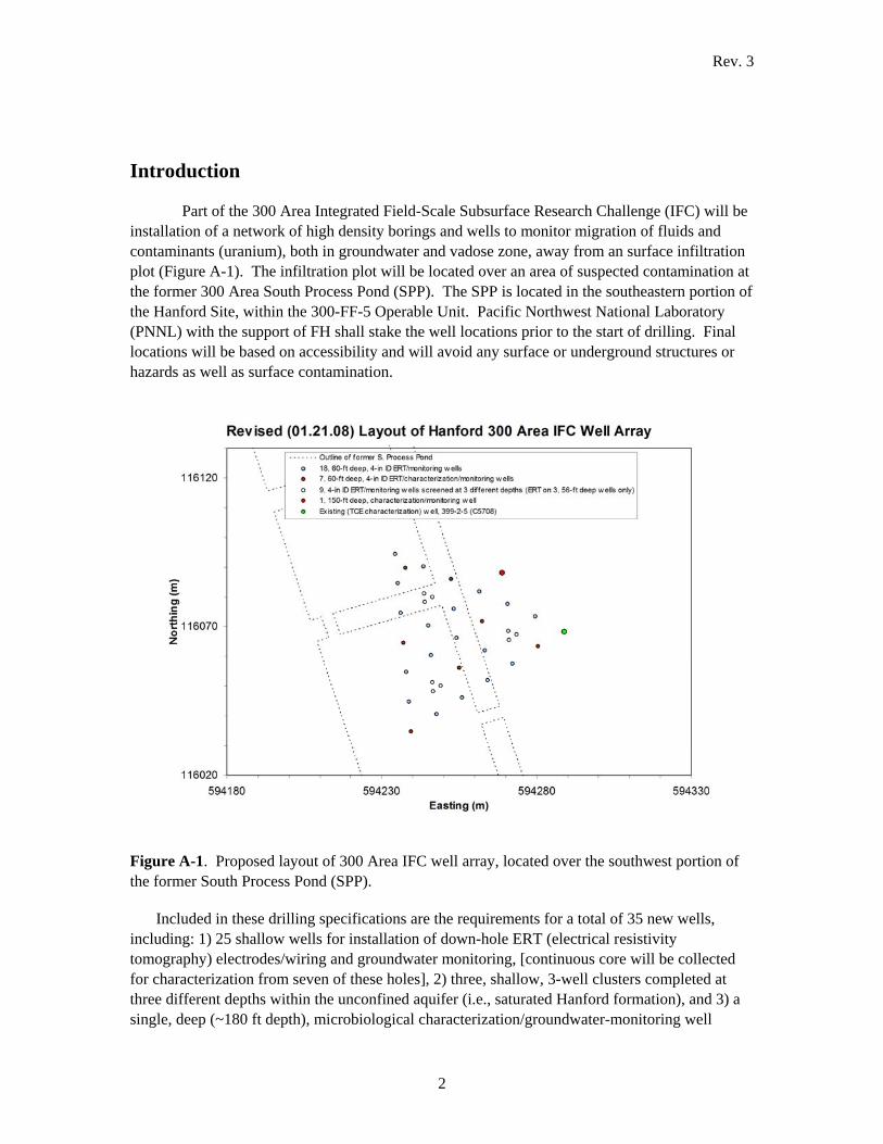
Part of the 300 Area Integrated Field-Scale Subsurface Research Challenge (IFC) will be installation of a network of high density borings and wells to monitor migration of fluids and contaminants (uranium), both in groundwater and vadose zone, away from an surface infiltration plot (Figure A-1). The infiltration plot will be located over an area of suspected contamination at the former 300 Area South Process Pond (SPP). The SPP is located in the southeastern portion of the Hanford Site, within the 300-FF-5 Operable Unit. Pacific Northwest National Laboratory (PNNL) with the support of FH shall stake the well locations prior to the start of drilling. Final locations will be based on accessibility and will avoid any surface or underground structures or hazards as well as surface contamination.
Figure A-1. Proposed layout of 300 Area IFC well array, located over the southwest portion of the former South Process Pond (SPP).
Included in these drilling specifications are the requirements for a total of 35 new wells, including: 1) 25 shallow wells for installation of down-hole ERT (electrical resistivity tomography) electrodes/wiring and groundwater monitoring, [continuous core will be collected for characterization from seven of these holes], 2) three, shallow, 3-well clusters completed at three different depths within the unconfined aquifer (i.e., saturated Hanford formation), and 3) a single, deep (~180 ft depth), microbiological characterization/groundwater-monitoring well

Rev. 3
3
drilled to the top of basalt. All wells will be completed with 4-in PVC. The relative locations of these wells are summarized in Figure A-1 and described in more detail in Table A-1.
The sonic drilling method is the preferred method for 1) the seven of 25 ERT-instrumented wells that require preservation of intact core material for physical and chemical characterization and 2) the deep microbiological characterization well (Table A-1). The remaining 28 wells may be drilled via either the cable tool (i.e., drive barrel) or sonic drilling method.

Rev. 3
4
New IFC Wells Type # Wells Preferred
Drill Method
Total Depth
(ft)
Borehole Diameter
Screen Screen Interval (ft)
Proposed Sampling Total # samples/well
Total # samples
Comments
ERT-instrumented/gw monitoring without core collection
18 cable tool or sonic
58 8" 4" PVC 31-56 Grab samples every 2 ft 29 grab samples* 464 grab samples*
sandpack below 10' depth; one well to be used as saturated-zone injection well
ERT-instrumented/gw monitoring with core collection
7 sonic 58 8" 4" PVC 31-56 4 holes continuous core in 0.5 ft lexan liners within 5-ft long, min. 4-in ID split spoon; 3 holes collected in 2-ft long sections of lexan, approximately the same diameter as the core barrel OD, at surface (i.e. grab samples)
12 split spoons or 58, 1-ft lexan liners; 29, 2-ft core samples
84 split spoons or 406, 1-ft lexan liners; 203, 2-ft core samples
continuous core (min 4" OD); sandpack below 10' depth
3-well cluster (multi-level) gw monitoring
3 clusters
cable tool or sonic
37, 46, 57
8" 4" PVC 30-35, 42-44, 53-55
Grab samples every 2 ft 66 grab samples/cluster*
198 grab samples*
ERT on deep (56 ft) well only (sandpack below 10' depth)
Deep characterization; gw monitoring
1 sonic ~180 8" 4" PVC 660-140 ~60 ft of core collected in lexan liners, from five intervals (30-35’, 50-70 ‘, 95-100’, 122’-132 ft’, and 170 ft to TOB); grab samples every 2 ft between core runs
Up to 12, 5-ft split-spoon segments; 60 grab samples
Continuous screen to test groundwater across redox boundaries in Ringold Formation
Total wells 35
*collected at surface by emptying core barrel into 5 gal. buckets or capped lexan liners (if collected by the sonic method use 2-ft long sections of lexan, approximately the same diameter as the core barrel OD)
Table A-1. Drilling, sampling and well-completion information for 35 new IFC wells.

Rev. 3
5
The site hydrogeology is illustrated in Figure A-2, based on borehole (399-2-5) recently drilled over the backfilled South Process Pond to detect TCE along the perimeter of the IFC well array (Figure A-1). Being immediately adjacent to the IFC site this well provides a reasonable approximation for the thicknesses and types of strata to be encountered in the new IFC wells. Expected strata include 13 ft of backfill overlying ~20 ft of unsaturated, coarse-grained flood deposits (Hanford formation). Below the water table lie ~23 ft more of Hanford formation (Figure A-2). The contact with the underlying Ringold Formation lies at ~56 ft below ground surface. The top of the fluvial-lacustrine Ringold Formation, consisting of fine sand to silt, forms an aquitard separating the Hanford formation portion of the unconfined aquifer from the locally semi-confined Ringold Unit E coarse sands and gravels below. About 60 ft of Ringold Unit E overlies a thick (~50 ft) fine-grained Ringold sequence (i.e., Ringold lower mud). Based on a few deep wells located elsewhere in the 300 Area, the top of basalt is estimated at ~180 ft bgs.
The water table, based on hydrographs from nearby wells over the last 10-20 years, ranges from a high elevation of 107.3 m (~25 ft depth) to low of 104.3 m (~35 ft depth). The wide fluctuation in the water table is a direct reflection of changes in seasonal river stage in the adjacent Columbia River. The average low water table in this area is about 33 bgs (105 m elev.).
While drilling it is important for the well-site geologist to produce a comprehensive, detailed geologic and photographic log of borehole cuttings. In order that the logging occurs in a complete and consistent manner as possible the well-site geologist shall follow PNNL procedure DO-1 (Standardized Geologic Description of Sediment Samples), which provides instructions for recording hydrogeologic information in a manner most useful to PNNL. The procedure includes the preferred methods for describing texture, sorting, color, mineralogy, moisture, etc. In addition to a detailed geologic log the well-site geologist or their designate shall keep as complete a photographic log as possible of cuttings retrieved from each of the 35 boreholes.

Rev. 3
6
Figure A-2. Hydrogeology in the vicinity of the IFC site based on well 399-2-5.
Rev. 3
7
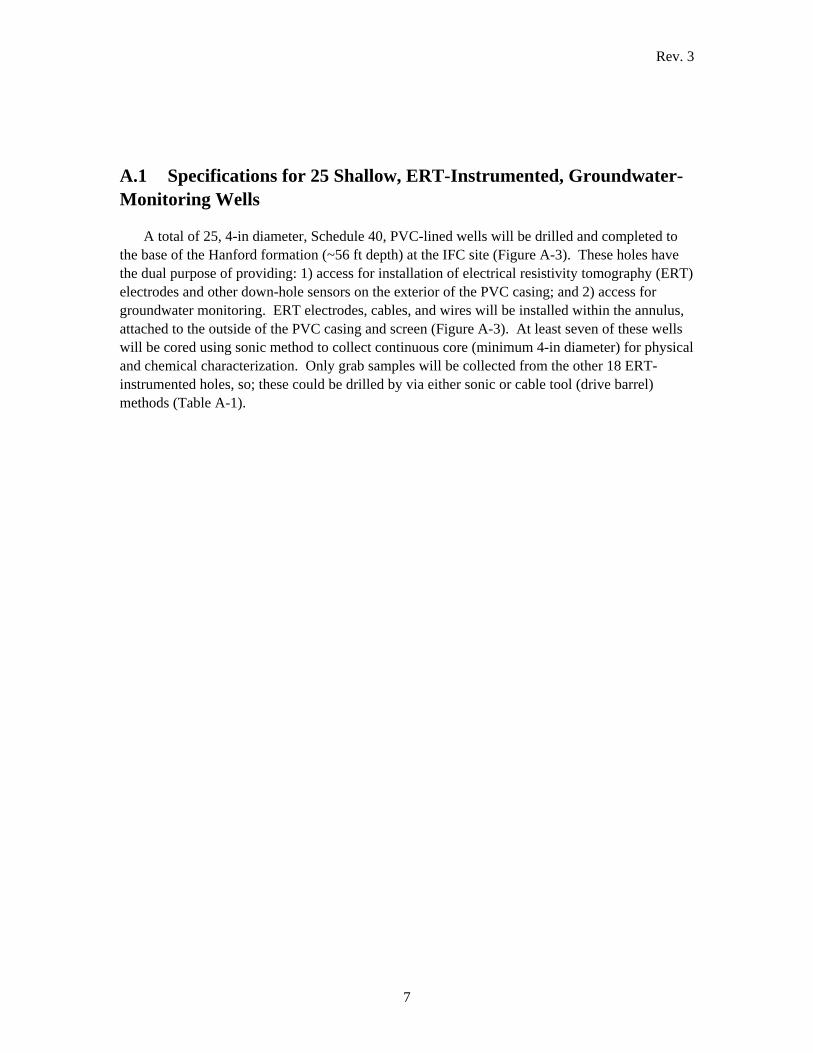
A.1 Specifications for 25 Shallow, ERT-Instrumented, Groundwater-Monitoring Wells
A total of 25, 4-in diameter, Schedule 40, PVC-lined wells will be drilled and completed to the base of the Hanford formation (~56 ft depth) at the IFC site (Figure A-3). These holes have the dual purpose of providing: 1) access for installation of electrical resistivity tomography (ERT) electrodes and other down-hole sensors on the exterior of the PVC casing; and 2) access for groundwater monitoring. ERT electrodes, cables, and wires will be installed within the annulus, attached to the outside of the PVC casing and screen (Figure A-3). At least seven of these wells will be cored using sonic method to collect continuous core (minimum 4-in diameter) for physical and chemical characterization. Only grab samples will be collected from the other 18 ERT-instrumented holes, so; these could be drilled by via either sonic or cable tool (drive barrel) methods (Table A-1).

Rev. 3
8
Figure A-3. As-built diagram for the 25, shallow, ERT-instrumented groundwater monitoring wells.
Rev. 3
9
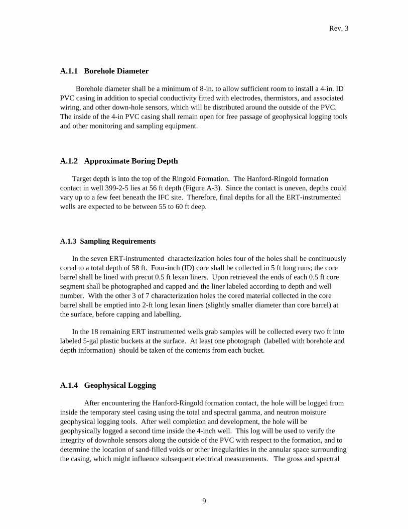
A.1.1 Borehole Diameter
Borehole diameter shall be a minimum of 8-in. to allow sufficient room to install a 4-in. ID PVC casing in addition to special conductivity fitted with electrodes, thermistors, and associated wiring, and other down-hole sensors, which will be distributed around the outside of the PVC. The inside of the 4-in PVC casing shall remain open for free passage of geophysical logging tools and other monitoring and sampling equipment.
A.1.2 Approximate Boring Depth
Target depth is into the top of the Ringold Formation. The Hanford-Ringold formation contact in well 399-2-5 lies at 56 ft depth (Figure A-3). Since the contact is uneven, depths could vary up to a few feet beneath the IFC site. Therefore, final depths for all the ERT-instrumented wells are expected to be between 55 to 60 ft deep.
A.1.3 Sampling Requirements
In the seven ERT-instrumented characterization holes four of the holes shall be continuously cored to a total depth of 58 ft. Four-inch (ID) core shall be collected in 5 ft long runs; the core barrel shall be lined with precut 0.5 ft lexan liners. Upon retrieveal the ends of each 0.5 ft core segment shall be photographed and capped and the liner labeled according to depth and well number. With the other 3 of 7 characterization holes the cored material collected in the core barrel shall be emptied into 2-ft long lexan liners (slightly smaller diameter than core barrel) at the surface, before capping and labelling.
In the 18 remaining ERT instrumented wells grab samples will be collected every two ft into labeled 5-gal plastic buckets at the surface. At least one photograph (labelled with borehole and depth information) should be taken of the contents from each bucket.
A.1.4 Geophysical Logging
After encountering the Hanford-Ringold formation contact, the hole will be logged from inside the temporary steel casing using the total and spectral gamma, and neutron moisture geophysical logging tools. After well completion and development, the hole will be geophysically logged a second time inside the 4-inch well. This log will be used to verify the integrity of downhole sensors along the outside of the PVC with respect to the formation, and to determine the location of sand-filled voids or other irregularities in the annular space surrounding the casing, which might influence subsequent electrical measurements. The gross and spectral
Rev. 3
10
gamma logs shall be run at a 6-inch vertical resolution while neutron moisture log shall be run at 3-inch vertical resolution.
A.1.5 Well Construction
All 25 ERT-instrumented holes will be constructed using a 4-in. PVC screen (with endcap and riser). A 25-ft long, 20-slot, continuous wire-wrap screen will extend from the contact with the Ringold Formation (~56 ft depth) to near the average low water table (105 m [~33 ft] depth). Special conductivity electrodes and wiring will be attached to the outside of the PVC during installation, so special care will be required lowering the assembly to the bottom of the hole under the supervision of the PNNL cognizant scientist (Andy Ward). After the PVC and electronics are in place, 10-20 mesh silica sand will be added to the annular void space as the temporary steel casing is pulled back. Sand will fill the annular space from the bottom of the hole to 10 ft below ground surface.
Surging of the sand pack should be performed between each 5 to 10 ft casing lift. Surging is especially important to get sand to fill in around ERT electrodes, cables, etc. which will be partially blocking the annular space between permanent and temporary casings.
A surface seal of cement grout or bentonite shall extend from 10 ft depth to ground surface. Flush-mount surface completions shall consist of a 10 to 12 in. well vault centered within a 4’X4’ concrete pad. The vault shall be equipped with a French drain designed to remove any water that may accumulate within the vault. The drain should extend at least 2 ft past the edge of the concrete pad and be constructed with sufficient slope to provide for effective drainage..
A.1.6 Special Instructions
Fluor Hanford will work with Washington State Department of Ecology if a variance is needed to construct these wells as specified. These wells are considered temporary, to be used in support of IFC field experiments, and will be decommissioned at the end of the IFC project. At the end of the project (~5 years) the wells will be backfilled with grout and abandoned.
A.2 Specifications for Multi-Level, Groundwater-Monitoring Well Clusters
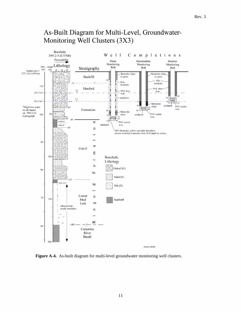
Three clusters, composed of three closely spaced wells each (Figure A-1), will be installed to monitor groundwater at various depths within the unconfined aquifer at the IFC site. Each cluster will consist of three wells completed with nominal 2.5-ft long, 4-in.diameter PVC screens at deep, intermediate, and shallow depths within the aquifer (Figure A-4). ERT instrumentation will be installed in only the deepest of each three-well cluster.
Rev. 3
11
Figure A-4. As-built diagram for multi-level groundwater monitoring well clusters.
Rev. 3
12
A.2.1 Borehole Depth
The deep, intermediate, and shallow monitoring wells will be drilled to ~57, 46, and 35 ft, respectively. The deeper wells will monitor the base of the aquifer within the Hanford formation along the contact with a fine-grained aquitard that lies at the top of the Ringold Formation (Figure A-4). The upper wells will monitor the top of the aquifer and capillary fringe zone within the Hanford formation.
A.2.2 Borehole/Well Diameter
All wells in this group will be drilled with nominal 8-in. diameter temporary casing to accommodate a 4-in. well.
A.2.3 Sampling Requirements
Grab samples will be collected every two feet to total depth from each of the 9 multi-level groundwater monitoring wells. These samples will be emptied into 5 gal plastic buckets at the surface. At least one photograph (labelled with borehole and depth information) should be taken of the contents from each bucket.
A.2.4 Geophysical Logging
Down-hole spectral-gamma and neutron-moisture geophysical logging will be performed to ~57 ft depth with the temporary steel casing solely on the deeper well within each cluster. After well completion and development the hole will be geophysically logged a second time inside the 4-inch PVC well. This log will be used to verify the integrity of down-hole ERT electrodes and other equipment along the outside of the PVC with respect to the formation and determine the location of sand-filled voids or other irregularities in the annular space surrounding the casing, which might influence electrical measurements. The gross and spectral gamma logs shall be run at a 6-inch vertical resolution while neutron moisture log shall be run at 3-inch vertical resolution.
A.2.5 Well Construction
A.2.4.1 Deep Monitoring Well. After this hole is drilled to about 57 ft a 2.5-ft long, 4-in. (ID), 20-slot, schedule 40 PVC screen (actual screen length = 2 ft) will be installed at the base of the Hanford formation and unconfined aquifer (~53-55 ft). Sand pack will be placed from two feet below to two feet above the top of the screen. To avoid hydraulic interference with other nearby wells within the cluster a minimum 5-ft thick bentonite seal will be placed above the
Rev. 3
13
screen. Because this well will be instrumented for ERT and other sensors along the outside of the PVC, a sand pack (10-20 mesh) will be placed above the bentonite seal. A surface seal of bentonite chips or grout shall extend from 10 ft depth to ground surface. Flush-mount surface completions shall consist of a 10 to 12 in. well vault centered within a 4’X4’ concrete pad. The vault shall be equipped with a French drain designed to remove any water that may accumulate within the vault. The drain should extend at least 2 ft past the edge of the concrete pad and be constructed with sufficient slope to provide for effective drainage.
A.2.4.2 Intermediate Monitoring Well. After this hole is drilled to about 46 ft a 2.5-ft long, 4-in. (ID), 20-slot, schedule 40 PVC screen (actual screen length = 2 ft) will be installed near the middle of the unconfined aquifer (~42-44 ft). Sand pack (10-20 mesh) will be placed from two feet below to two feet above the top of the screen. A 5-ft bentonite seal will be placed above the sand pack, followed by a continuous seal of bentonite chips or grout to the surface. Flush-mount surface completions shall consist of a 10 to 12 in. well vault centered within a 4’X4’ concrete pad. The vault shall be equipped with a French drain designed to remove any water that may accumulate within the vault. The drain should extend at least 2 ft past the edge of the concrete pad and be constructed with sufficient slope to provide for effective drainage.
A.2.4.3 Shallow Monitoring Well. After this hole is drilled to about 37 ft a 5-ft long, 4-in. (ID), 20-slot, schedule 40 PVC screen (actual screen length = 2 ft) will be installed at the top of the unconfined aquifer (~31-33 ft). Sand pack (10-20 mesh) will be placed from two feet below to two feet above the top of the screen. The annulus will be sealed to the surface above the sand pack (starting ~28 ft depth). Either bentonite chips or grout can be used for the seal. It’s possible that during certain times of year the screen in the shallowest wells in clusters could lie above the water table and be temporarily dry. But because the source for uranium contamination may lie in this zone of fluctuating water table it is important to target this zone for groundwater analysis. Flush-mount surface completions shall be imbedded into a 4’X4’ cement pad equipped with a 10 to 12 in. vault and French drain to collect any surface runoff and to keep surface water from entering the inside of the well.
A.2.6 Special Instructions
Fluor Hanford will work with Washington State Department of Ecology if a variance is needed to construct these wells as specified. These wells are considered temporary, to be used in support of IFC field experiments, and will be decommissioned at the end of the IFC project. At the end of the project (~5 years) the wells will be backfilled with grout and abandoned.
A.3 Specifications for the Deep-Characterization / Groundwater-Monitoring Well
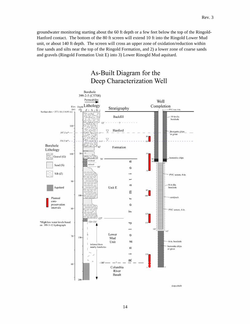
One combination deep-characterization / monitoring well will be drilled to the top of basalt near the perimeter of the IFC test-plot area (Figure A-1). During drilling, intact core samples will be collected from five separate intervals, within both the Hanford and Ringold formations, for microbiological characterization (Figure A-5). After drilling, a single screen will be installed for
Rev. 3
14
groundwater monitoring starting about the 60 ft depth or a few feet below the top of the Ringold- Hanford contact. The bottom of the 80 ft screen will extend 10 ft into the Ringold Lower Mud unit, or about 140 ft depth. The screen will cross an upper zone of oxidation/reduction within fine sands and silts near the top of the Ringold Formation, and 2) a lower zone of coarse sands and gravels (Ringold Formation Unit E) into 3) Lower Rinogld Mud aquitard.

Rev. 3
15
Figure A-5. As-built diagram for the deep-characterization well.
A.3.1 Borehole Depth
The deep characterization borehole will advance to the top of basalt (TOB). Only a few wells have penetrated basalt within the 300 Area and none of these lie in the immediate vicinity of the IFC site. Furthermore, since the TOB is an uneven and sloping surface, the exact depth within the IFC site is uncertain. Best estimate is ~180 +/- 10 ft. Coring of the lowest interval will begin ~170 ft and continue into the TOB wherever that is encountered. From TOB an attempt will be made to drill 5 ft into the weathered upper part of the basalt or refusal, which ever occurs first.
A.3.2 Borehole/Well Diameter
To begin, the hole diameter must be sufficient to accommodate a 4-inch core barrel through the bottom portion of the hole to TOB. Assuming the temporary casing needs to be downsized at each of two aquitards, starter casing will need to be at least 10 in diameter. The 10-in temporary casing will be downsized to 8-inch below the contact with the Ringold Formation (~58 ft). Casing will need to be downsized again to 6-inch at the top of the Ringold Lower Mud unit (~130 ft) to prevent any inadvertent intercommunication between aquifers.
A.3.3 Sampling Requirements
A total of 60 ft of core shall be collected in five foot runs from 30-35 ft, 50-70 ft, 95-100 ft, 122-132 ft, and 170 ft to the top of basalt (~180 ft). The core barrel shall be lined with precut 0.5 ft lexan liners. Upon retrieveal the ends of each 0.5 ft core segment shall be photographed and capped and the liner labeled according to depth and well number.
In between core runs grab samples will be collected every two ft into labeled 5-gal plastic buckets at the surface. At least one photograph (labelled with borehole and depth information) should be taken of the contents from each bucket.
A.3.4 Geophysical Logging
Down-hole spectral gamma and neutron-moisture geophysical logging will be performed within the temporary steel casing at three different stages. Logging will occur prior to downsizing for each of the first two strings of temporary casing at approximately 58 and 130 ft below ground surface, as well as at completion of drilling (~180 ft depth) and prior to well installation. The gross and spectral gamma logs shall be run at a 6-inch vertical resolution while neutron moisture log shall be run at 3-inch vertical resolution.

Rev. 3
16
A.3.5 Well Construction
At the end of drilling, after the borehole has reached total depth (~180 ft), the bottom of the hole will be backfilled with bentonite to base of the well (~140 ft) (Figure A-5). The well will be constructed using 4-in diameter , schedule 40 PVC. The well screen will be 10-slot, continuous wire wrap and 80-ft in length (60-140 ft depth). A sand pack of 20-40 mesh Colorado Silica Sand will be placed from two feet below to two feet above the top of the screen. Surging of the sand pack shall be performed periodically as sand is added. Surging of the sand pack shall occur at a minimum of every 20 ft. At least two feet of bentonite chips followed by chips or grout will be installed above the sandpack to the surface.
A.3.6 Special Requirements
Special attention shall be made to collect as continuous core as possible within the 5 cored intervals shown on Figure A-6. Assuming the cores are collected using the sonic drilling method, split-spoons lining the core barrel should not exceed 6 ft in length, in order to minimize core loss due to blocking off of the drill bit. Furthermore, to keep recovered core from sliding out of the core barrel, especially within the loose Hanford formation, a core catcher or other effective retention device should be placed at the bottom of the core barrel.
Fluor Hanford will work with Washington State Department of Ecology if a variance is needed to construct these wells as specified. These wells are considered temporary, to be used in support of IFC field experiments, and will be decommissioned at the end of the IFC project. At the end of the project (~5 years) the wells will be backfilled with grout and abandoned.
A.4 Schedule
Drilling activities shall begin no later than February 1, 2008 and be completed by May 1 2008. All well installation shall be completed by July 30, 2008.
A.5 Well Decommissioning
At the end of the project (~5 years) all IFC wells specified in this report will be decommissioned via backfilling with grout to the surface. Decommissioning of the wells is made easier by the flush-mount surface completions for most of the new IFC wells, which can easily be decommissioned by backfilling with grout. The porous cup samplers (in vadose injection wells) can be decommissioned via filling with a thin grout slurry from the surface. The IFC project has set aside the necessary funds ($220,000) for site decommissioning at the close of the project.