drawings/13ulv50r submittal.pdf · submittal data sheet model gpl electric pump controller audible...
TRANSCRIPT


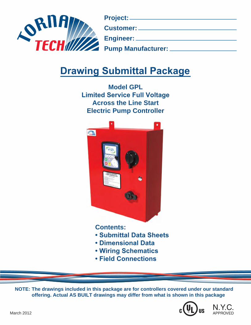
The drawings included in this package are for controllers covered under our standard offering. Actual AS BUILT drawings may differ from what is shown in this package
NOTE:
March 2012
Contents:• Submittal Data Sheets• Dimensional Data• Wiring Schematics• Field Connections
Model GPLLimited Service Full Voltage
Across the Line StartElectric Pump Controller
Project:Customer:Engineer:Pump Manufacturer:
Drawing Submittal Package
Submittal Data Sheet Model GPL Electric Pump Controller
New York City
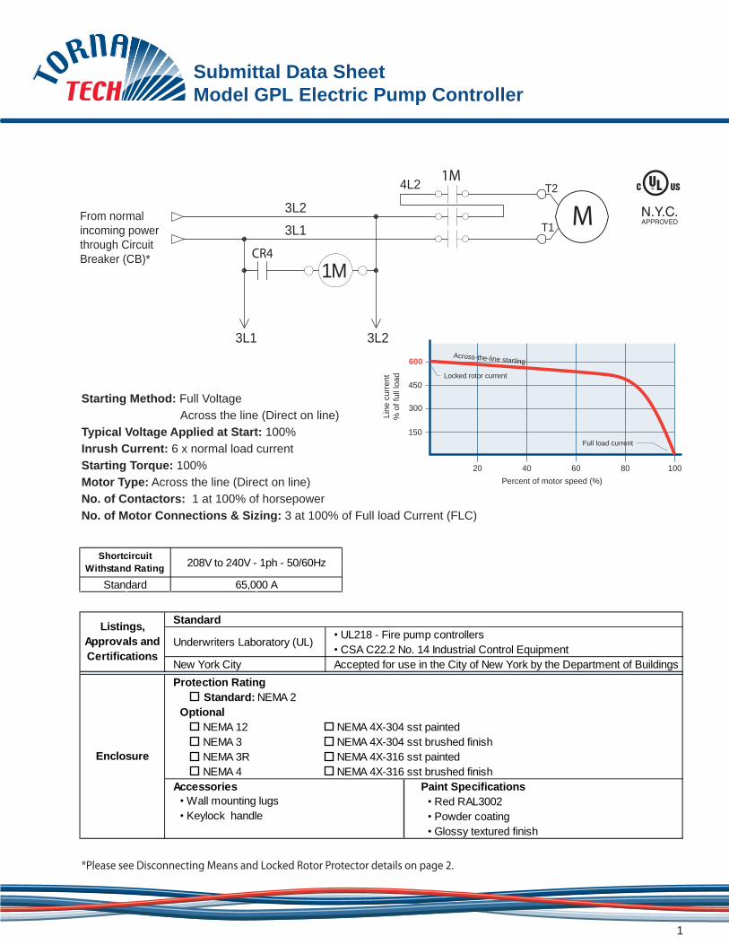
NEMA 12 NEMA 4X-304 sst paintedNEMA 3 NEMA 4X-304 sst brushed finishNEMA 3R NEMA 4X-316 sst painted NEMA 4 NEMA 4X-316 sst brushed finish
Accessories• Wall mounting lugs• Keylock handle
Paint Specifications• Red RAL3002• Powder coating• Glossy textured finish
Listings, Approvals and Certifications
Standard
Underwriters Laboratory (UL)• UL218 - Fire pump controllers• CSA C22.2 No. 14 Industrial Control EquipmentAccepted for use in the City of New York by the Department of Buildings
Enclosure
Protection Rating Standard: NEMA 2Optional
*Please see Disconnecting Means and Locked Rotor Protector details on page 2.
Standard 65,000 A
Shortcircuit Withstand Rating 208V to 240V - 1ph - 50/60Hz
M From normal incoming power through CircuitBreaker (CB)*
3L13L2
4L2 1M
3L1 3L2
1M
T2
T1
CR4
600Across-the-line starting
Locked rotor current
Full load current
Percent of motor speed (%)
Line
cur
rent
% o
f ful
l loa
d
20 40 60 80 100
450
300
150
Starting Method: Full Voltage Across the line (Direct on line)Typical Voltage Applied at Start: 100%Inrush Current: 6 x normal load currentStarting Torque: 100%Motor Type: Across the line (Direct on line)No. of Contactors: 1 at 100% of horsepowerNo. of Motor Connections & Sizing: 3 at 100% of Full load Current (FLC)
1

Submittal Data Sheet Model GPL Electric Pump Controller
Surge Suppression
Service Entrance
Rating
Pressure and Event
Recorder
• Pressure readings with date stamp• Event recording with date stamp • Stored in memory for lifetime of controller • Data viewable on operator interface display screen • Downloadable by USB port to external memory device
Pressure Sensing
• Pressure transducer for fresh water application• Pressure sensing connection 1/2” Female NPT• Rated for 0-500psi working pressure• Internally mounted
Limitations
• Across the line starting only• Horsepower rating of maximum 30hp• Can only be installed where acceptable by the authority having jurisdiction • Not accepted in FM insured property
Emergency Start Handle
• Push and slide to lock• Across the line start (direct on line)
Surge arrestor rated to suppress surges above line voltage
Disconnecting Means &
Locked Rotor Protector
Circuit breaker (inverse time non ajustable) rated between 150% and 250% of motor full load current
Suitable as service entrance equipment
Electrical Readings
• Voltage phase to phase• Amperage of each phase when motor is running
Pressure Readings
• Continuous system pressure display• Cut-in and Cut-out pressure settings
2

Submittal Data Sheet Model GPL Electric Pump Controller
Audible Alarm• Power available • Locked rotor • Manual start• Phase reversal • Periodic test • Deluge valve start • Motor run • Fail to start • Remote automatic start • Pump room alarm • Low discharge pressure • Remote manual start • Motor trouble • Low pump room temperature • Overcurrent• Phase loss • Pump room temperature (ºF or ºC) • Undercurrent• Phase unbalance • Pump on demand/Automatic start • Undervoltage• Low water level • Emergency start • Overvoltage
• Overvoltage • Undervoltage • Phase unbalance• Low pump room temperature
gh p mp r om • High pump room temperature
• Overcurrent • Fail to start• Undercurrent • Ground fault
• Expandable storage• Multi-language
• Minimum run timer** (off delay)• Se uent al start tim r ( n • Sequential start timer (on delay)• Periodic test timer• Pressure • Non-pressure• Automatic• Non-automatic
** Can only be used if approved by the AHJ
Visual Indications and
Alarms
Remote Alarm Contacts
SPDT-8A-250V.AC• Power available • Phase reversal• Motor run • Common pump room alarm
• Common motor trouble
ViZiTouch Operator Interface
• Embedded microcomputer with software PLC logic• 4.2” color touch screen (HMI technology)• Upgradable software
4” alarm bell - 85 dB at 10ft. (3m)
Automatic Start• Start on pressure drop • Remote start signal from automatic device
Manual Start
• Start pushbutton• Run test pushbutton• Deluge valve start• Remote start from manual device
Field Adjustable & Visual Countdown
Operation
Actuation Visual Indication
Mode
Stopping • Manual with Stop pushbutton• Automatic after expiration of minimum run timer **
Timers
3

Submittal Data Sheet Model GPL Electric Pump Controller
5
ViZi Touch Operator Interface
??
4
9
11 12
10
13
5 6 7
3
2
1
8
1 - Power LED2 - Color touch screen3 - Alarm LED4 - HOME page button 5 - ALARM page button6 - CONFIGURATION page button7 - HISTORY page button
8 - USB port9 - START button10 - Contextual navigation pad11 - STOP button12 - RUN TEST button13 - HELP button


AlbAny PumP ComPAny ltd. cep-860 SerieS 0-4 gpm/0-150 pSi 3/8” npt
utility duty geAr PumPsthe cep series Utility gear pumps are a close tolerance, low flow, high pressure positive displacement pump. A standard in the fire sprinkler industry for excess pressure service.
APPliCAtions• Excess Pressure Pump• Liquid Transfer/Circulation• Small Booster Jockey Pump• Spray Nozzles/Misting• Hydraulic/Hydrostatic
phone: (888) 334-3348 | FAx: (888) 335-3391 | Web: WWW.AlbAnypUmp.com | emAil: [email protected]
Flow: 0-4.6 GPM | 0-0.29 L/s | 0-1.04 m3/hr
Pressure: 0-150 PSI | 10.5 Bar | 0-346 Ft.
FeAtures• Precision Spur Style Gears • Self Priming due to close manufacturing tolerances• Suction lift of up to 20 feet• Pump housings are of bronze• Pump shafts are of stainless steel• Lip seals of Buna or Viton • Carbon graphite shaft bearings• Bearings never need lubrication• Easy maintenance and service
rotAtion• Precision Spur Style Gears • Self Priming due to close manufacturing tolerances• Suction lift of up to 20 feet• Pump housings are of bronze
mAintenAnCeTo ensure a long life to this pump a strainer is alwaysrecommended in front of the pump inlet.
PerFormAnCe
0 25 50 75 100 125 150
PSI
6.0
5.0
4.0
3.0
2.0
1.0
0
1.2
1.0
.80
.60
.40
.20
0
P
GPM H
HP - 1750 RPM
Capacity 1750 RPM
Performance Curve - CEP 860
dimensionsimensions:
5.983.006.50
4.875
3/8" NPT
1/2 HP2.32
2.85
8.2
sPeCiFiCAtionsPORTS 3/8“ NPT / 9.525 mm
CAPACITY 4.6 USGPM / 0.29 L/s (Max.)
PRESSURE 150 PSI / 10.5 Bar (Max.)
INLET PRESSURE 50 PSI / 3.5 Bar (Max.)
TEMPERATURE 225° F (100 C) (Buna Seal)


For Commercial, Institutional and Industrial Applications
ES-530C
Job Name ––––––––––––––––––––––––––––––––––––––––––– Contractor ––––––––––––––––––––––––––––––––––––––––––––
Job Location ––––––––––––––––––––––––––––––––––––––––– Approval –––––––––––––––––––––––––––––––––––––––––––––
Engineer ––––––––––––––––––––––––––––––––––––––––––––– Contractor’s P.O. No. –––––––––––––––––––––––––––––––––––
Approval ––––––––––––––––––––––––––––––––––––––––––––– Representative ––––––––––––––––––––––––––––––––––––––––
Series 530CCalibrated Pressure Relief Valves
Sizes: 1⁄2" or 3⁄4" (15 or 20mm)
Series 530C Calibrated Pressure Relief Valves are springoperated brass valves designed for use only as protectionfrom the build up of excessive pressure in systems contain-ing water, oil or air. Series 530C valves incorporate a cali-brated adjustment feature for setting the valve to the reliefpressure required. These valves are ideally suited for bypassthermal expansion relief.
Features
• Calibrated adjustment feature for setting valve to reliefpressure required
• Adjustable range 50 – 175psi (3.4 – 12.1 bar)
• All brass construction
• All stainless steel spring
• Buna-N disc on machined body seat
• Inlet (bottom), male NPT threaded
• Outlet (side), female NPT threaded
Pressure – Temperature
Maximum Temperature: 180°F (82°C)
Spring Ranges1⁄2" or 3⁄4" (15 or 20mm): 50 – 175psi (3.4 – 12.1 bar)3⁄4" (20mm): 100 – 300psi (6.9 – 20.7 bar)
Application Note: The Watts Series 530C are not ASMEapproved safety relief valves and should not be used in sys-tem application with this requirement.
3⁄4"
(20mm)
1⁄2"
(15mm)
X = Set Point Flow
0 5 10 15 20 25 30 35 40 gpm
19 38 57 76 95 114 133 152 lpm
psi bars
300 20.7
275 18.9
250 17.2
225 15.5
200 13.8
175 12.1
150 10.3
125 8.6
100 6.9
75 5.2
50 3.4
25 1.7
Inle
t P
ress
ure
Capacity (530C)
2
7
6
5
4
3
1
Model 530C
MODEL SIZE (DN) DIMENSIONS WEIGHT
Height Width
in. mm in. mm in. mm lbs. kg.
530C 1⁄2 or 3⁄4 15 or 20 3 76 15⁄8 41 .37 0.17
Materials
1. Body Brass
2. Bonnet Brass
3. Disc Holder Brass
4. Disc Buna-N (Nitrile)
5. Adjustable Spring Stainless Steel
6. O-ring Buna-N (Nitrile)
7. Spring Washer Brass
Watts product specifications in U.S. customary units and metric are approximate and are provided for reference only. For precise measurements,please contact Watts Technical Service. Watts reserves the right to change or modify product design, construction, specifications, or materials withoutprior notice and without incurring any obligation to make such changes and modifications on Watts products previously or subsequently sold.
ES-530C 0630 ©Watts Regulator Company, 2006
USA: 815 Chestnut St., No. Andover, MA 01845-6098; www.watts.com
Canada: 5435 North Service Rd., Burlington, ONT. L7L 5H7; www.wattscanada.ca
W a t e r S a f e t y & F l o w C o n t r o l P r o d u c t s

MATERIAL LIST NO. DESCRIPTION MATERIAL
1 Set Screw Steel
2 Hand Wheel Iron
3 Yoke Bushing Brass
4 Stem Brass
5 Packing Gland Brass
6 Cap Screw Steel
7 Packing Graphite Non-Asb.
8 Bonnet Bronze
9 Spirol Pin Stainless Steel
10 Wedge Bronze
11 Body Bronze
Size A B C Ship Wgt.
(lbs.)
Qty.
Unit Pack
Qty.
Per Case
1 2.55 6.55 7.97 3.85 6 18
1 ¼” 2.81 7.61 9.47 6.26 2 12
1 ½” 2.86 7.84 9.75 6.55 2 6
2” 3.09 8.88 11.22 9.96 2 6
UNITED BRASS WORKS, INC. 714 S. Main St., Randleman, NC 27317
Tel: 800-334-3035 Fax: 800-498-4696 www.ubw.com
Model 18 Gate Valve Bronze Screwed Ends
Outside Screw & Yoke
UL Listed / FM Approved @ 175 lbs. WOG
200 WOG @ 180 ° Max
100% Pressure Tested
Rising Stem
MEA Approval 255-93-E


