drawing in 3d (again) - uw graphics...
TRANSCRIPT

Drawing in 3D (again) (this time with depth)
CS559 – Spring 2016 Lecture 8
February 18, 2016

What does it take to do this?
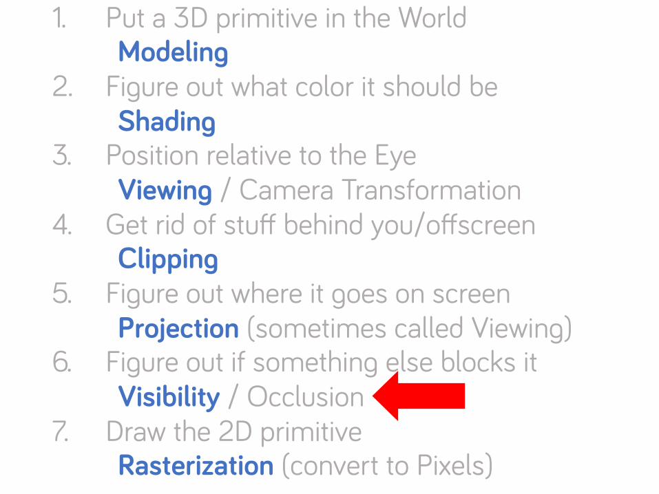
1. Put a 3D primitive in the World 2. Figure out what color it should be 3. Position relative to the Eye 4. Get rid of stuff behind you/offscreen 5. Figure out where it goes on screen 6. Figure out if something else blocks it 7. Draw the 2D primitive

1. Put a 3D primitive in the World Modeling
2. Figure out what color it should be Shading
3. Position relative to the Eye Viewing / Camera Transformation
4. Get rid of stuff behind you/offscreen Clipping
5. Figure out where it goes on screen Projection (sometimes called Viewing)
6. Figure out if something else blocks it Visibility / Occlusion
7. Draw the 2D primitive Rasterization (convert to Pixels)
Did some, will do more
A li%le for P4
Last 0me (review)
Not much to say
Last 0me (review)
Today
Not much to say (FCG 8)

Viewing / Projection
How to get from the object to the screen? A transformation between coord systems Once we get to the screen, then draw a 2D primitive. Like a painter.

In case it wasn’t obvious. . .
We transform points If you want to transform a line/triangle
Transform its points Re-assemble it after transforming (e.g. draw the 2D primitive)

3D to 2D
Do we lose a dimension? No – we actually need to keep it Yes – but we’ll just ignore Z The screen as a fishtank

Canonical View Volume Normalized Device Coordinates -1 to 1 (zero centered) XY is screen (y-up) Z is towards viewer (right handed)
Negative Z is into screen (so some prefer left-handed)
Viewport transform: NDC -> Pixels

All the coordinate systems Window (Screen) – in pixels
Normalized Device – [-1 1]
Camera / Eye
World
Object . . .
Local
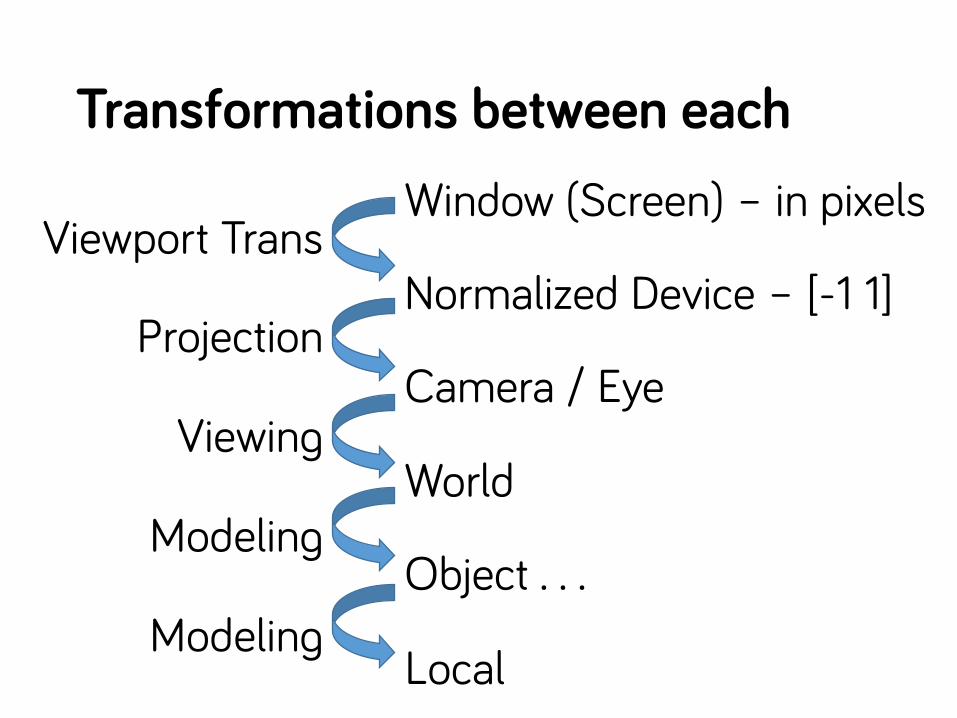
Transformations between each Window (Screen) – in pixels
Normalized Device – [-1 1]
Camera / Eye
World
Object . . .
Local
Viewport Trans
Projection
Viewing
Modeling
Modeling

From object to eye: ModelView
Modeling matrix: object to world Viewing matrix: world to eye / camera
Rigid Transformation (rotate/translate) Invert the camera’s model matrix Build a “LookAt / LookFrom” matrix

How to describe cameras?
Rotate and translate (and scale) the world The camera is a physical object
(that can be rotated and) Easier ways to specify cameras
Look from / Look at / vup

Lookfrom / Lookat / Vup
Don’t compute angles! Eye point = LA Z axis (camera sight) = LF-LA X axis (camera right) = Z x Vup Y axis (camera up) = X x Z (normalize, and flip directions as needed)

Next Problem: Projection
Convert 3D (eye coordinates) to 2D (screen) A transformation Types:
Orthographic Perspective some others we won’t talk much about
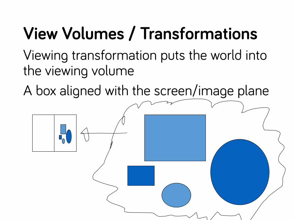
View Volumes / Transformations Viewing transformation puts the world into the viewing volume A box aligned with the screen/image plane

Orthographic Projection Projection = transformation that reduces dimension Orthographic = flatten the world onto the film plane

Orthographic Projection
Scale X and Y to fit things on screen Note: we can look in any direction
we are already in camera coodinates!

Orthographic Projections
Simple Preserves Parallelism (and some distances) Objects far away same size as close Looks weird

Perspective Projection Farther objects get smaller Eye (or focal) point Image plane View frustum (truncated pyramid) Two ways to look at it:
Project world onto image plane Transform world into rectangular view volume (that is then orthographically projected)

Perspective Assumptions
There is a single focal point Simplifying Assumptions: (not required) Image plane orthogonal to view direction Image plane centered on view direction

Perspective Eye point Film plane Frustum Simplification
Film plane centered with respect to eye Sight down Z axis • Can transform world to fit

Pinhole Camera
d

Basic Perspective Similar Triangles Warning = using d for focal length (like book)
F will be “far plane”
D = focal length
z
y y’

Use Homogeneous coordinates! Use divide by w to get perspective divide Issues with simple version:
Font / back of viewing volume Need to keep some of Z in Z (not flatten)

Simplest Projective Transform
ACer the divide by w… Note that this is dx/z, dy/z (as we want) Note that z’ is 1/z (we can’t keep Z) Fancier forms scale things correctly
dxdy1z
!
"
####
$
%
&&&&
=
d 0 0 00 d 0 00 0 0 10 0 1 0
!
"
####
$
%
&&&&
xyz1
!
"
####
$
%
&&&&

The real perspective matrix N = near distance, F = far distance Z = n put on front plane, z=f put on far plane

Shirley’s Perspective Matrix
After we do the divide, we get an unusual thing for z – it preserves order, keeps n&f

The TWGL perspective matrix
perspective(fov, aspect, zNear, zFar) → {Mat4} fov = field of view (specify focal length) aspect ratio (witdth of image) assuming height is 1

Field of View
d
ϴ

znear and zfar are distances the camera sights down the –Z axis
It’s making things LeC Handed! (?)

Transformations between each Window (Screen) – in pixels
Normalized Device – [-1 1]
Camera / Eye
World
Object . . .
Local
Viewport Trans
Projection
Viewing
Modeling
Modeling
1. Put a 3D primitive in the World Modeling
2. Figure out what color it should be Shading
3. Position relative to the Eye Viewing / Camera Transformation
4. Get rid of stuff behind you/offscreen Clipping
5. Figure out where it goes on screen Projection (sometimes called Viewing)
6. Figure out if something else blocks it Visibility / Occlusion
7. Draw the 2D primitive Rasterization (convert to Pixels)

Visibility: What objects do you see? What objects are offscreen?
To avoid drawing them (generally called clipping)
What objects are blocked? Need to make things look solid
Assumes we have “filled” primitives Triangles, not lines
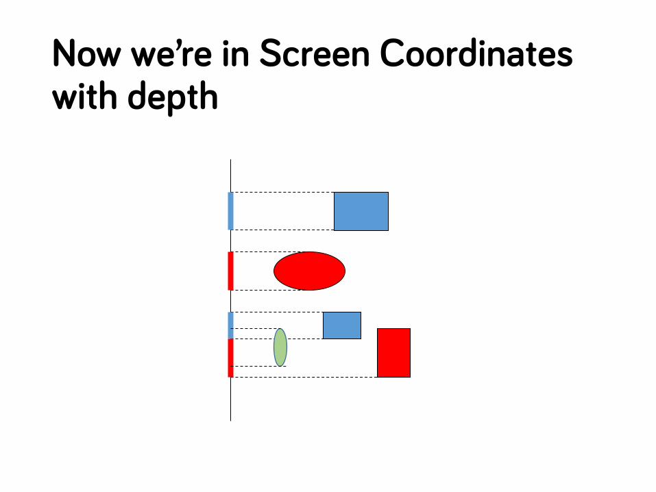
Now we’re in Screen Coordinates with depth

Bad ideas…
Last drawn wins sometimes object in back what you seen depends on …
Wireframe (nothing blocks anything)
hard to see what’s going on if complex

How to make objects solid
Physically-Based Analytic Geometry Object-space methods (order) Image-space methods (store per pixel)

Painter’s Algorithm
Order the objects Draw stuff in back first Stuff in front blocks stuff in back

Simple version
Pick 1 point for each triangle Sort by this one point (this is OK for P4)
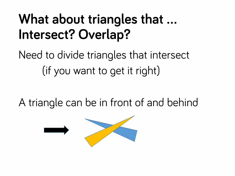
What about triangles that … Intersect? Overlap? Need to divide triangles that intersect
(if you want to get it right) A triangle can be in front of and behind

Downsides of Painters Algorithm
Need to sort O(n log n) need all triangles (not immediate)
Dealing with intersections = lots of triangles Need to resort when the camera moves
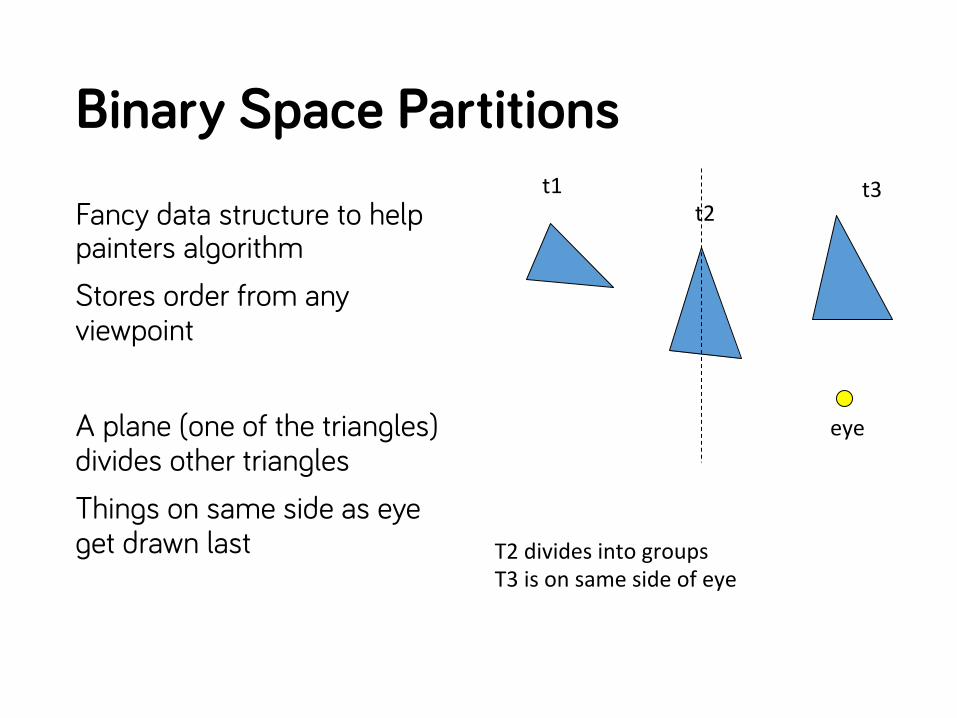
Binary Space Partitions Fancy data structure to help painters algorithm Stores order from any viewpoint A plane (one of the triangles) divides other triangles Things on same side as eye get drawn last
t1 t2
t3
eye
T2 divides into groups T3 is on same side of eye
Using a BSP tree Recursively divide up triangles Traverse entire tree
Draw farther from eye subtree Draw root Draw closer to eye subtree
Always O(n) to traverse (since we explore all nodes) No need to worry about it being balanced

Building a BSP tree
Each triangle must divide other triangles Cut triangles if need be
Goal in building tree: minimize cuts

Painters Problem 2: Overdraw
All triangles get drawn Even if something else will cover it Depth Complexity = # of things at each pixel Inefficient, uses lots of memory bandwidth

Z-Buffer
An image space approach Hardware visibility solution Throw memory at the problem Every pixel stores color and depth

Z-buffer algorithm
Clear all pixels to “farthest value” (-inf) for each triangle
for each pixel if new Z > old Z: // in front write new color and Z

Simple
The only change to triangle drawing: test Z before writing pixels
writeColor(@pixel) becomes:
readZ(@pixel) test writeZandColor(@pixel)

Notice…
Order of triangles usually doesn’t matter Except…
If the Z is equal, we have a tie We can decide if first or last wins Either way, order matters
Z-Fighting

Z-Fighting
Z Equal? Order matters Z Really close?
random numerical errors cause flips

Z-Resolution
Remember – we don’t have real Z we have 1/Z (bunches resolution)
Old days: integer Z-buffer was a problem Nowadays: floating point Z-buffers
Z-resolution less of an issue Keep near and far close

Transparent Objects
Draw object in back Draw transparent object in front But… Draw transparent object in front Draw object in back (Z-buffer prevents)
Overdraw
Still drawing all objects – even unseen Can save writes if front objects first Early z-test…
Avoid computing pixel color if it will fail z-test

Using the Z buffer
Give polygons in any order (except…) Use a Z-Buffer to store depth at each pixel Things that can go wrong:
Near and far planes matter Culling tricks can be problematic You may need to turn the Z-buffer on Don’t forget to clear the Z-Buffer!

Culling
Quickly determine that things cannot be seen – and avoid drawing them Must be faster to rule things out than to draw them

1. Put a 3D primitive in the World Modeling
2. Figure out what color it should be Shading
3. Position relative to the Eye Viewing / Camera Transformation
4. Get rid of stuff behind you/offscreen Clipping
5. Figure out where it goes on screen Projection (sometimes called Viewing)
6. Figure out if something else blocks it Visibility / Occlusion
7. Draw the 2D primitive Rasterization (convert to Pixels)

A Quick Word on Shading (for P4)
Color of triangle depends… Color per triangle (OK for P4) Color per vertex Color per pixel

Lighting basics
To simulate light, we need to know where the triangle is in the world Global Effects (other objects)
reflections, shadows, … Local Effects (how the light bounces off)
shininess, facing the light, …

Local Geometry
Normal Vector – sticks “out” of the triangle

Transforming Normal Vectors
Transform triangle, re-compute the normal or…
Normal is transformed by the inverse transpose of the transform
If the triangle is transformed by M The normal is tranformed by (M-1)T

Inverse Transpose?
Yes – ask Prof. Sifakis for the proof. (the book just asserts it as fact)
For a rotation, the inverse is the transpose
M = (M-1)T
But only for rotations …

What can I use a normal vector for?
Simplest lighting: Diffuse Shading If surface is pointing towards light, it gets more light
brightness ~= N • L N = unit normal vector L = unit light direction vector

We’ll look at this more in the future

Simple things for P4
High noon… C’ = ( ½ + ½ N • [0,1,0] ) C
Top and bottom…
C’ = ( ½ + ½ abs(N • [0,1,0] ) ) C Make sure N is a unit vector!

Program 4
Just like P3 (transform points) but… 1. Draw Triangles (solids) 2. Compute Normals (and shade) 3. Store triangles in a list and sort
Painter’s Algorithm Visibility

What coordinate system to compute lighting in?
Window (Screen)
Normalized Device – [-1 1]
Camera / Eye
World
Object . . .
Local
Normals lost
Projection loses normals
Camera space is OK
World space is good
Lights attached to objects?

1. Put a 3D primitive in the World Modeling
2. Figure out what color it should be Shading
3. Position relative to the Eye Viewing / Camera Transformation
4. Get rid of stuff behind you/offscreen Clipping
5. Figure out where it goes on screen Projection (sometimes called Viewing)
6. Figure out if something else blocks it Visibility / Occlusion
7. Draw the 2D primitive Rasterization (convert to Pixels)
Rasterization
Figure out which pixels a primitive “covers” Turns primitives into pixels

Rasterization
Let the low-level library take care of it Let the hardware take care of it Writing it in software is different than hardware Writing it today (with cheap floating point) is different than a few years ago

How does the hardware do it? (or did it last I learned about it) Find a box around the triangle For each pixel in the box
compute the barycentric coordinates check if they are inside the triangle
Do pixels in parallel (in hardware) otherwise, really wasteful
Barycentric coordinates are useful

Barycentric Coordinates
Any point in the plane is a convex combination of the vertices of the triangle
A
B C
P
P=αA+βB+ɣC α+ β + ɣ = 1 Inside triangle 0 <= α, β, ɣ <= 1

Where are we going next…
We’ve made a graphics pipeline Triangles travel through steps…
get turned into shaded pixels How do we use the hardware to make this go fast…