draught - home - prof. k. m. joshi the draught is one of the most essential systems of thermal power...
TRANSCRIPT

DRAUGHT
SYSTEMSYSTEM
By: Prof K. M.Joshi,Assi. Professor, MED,
SSAS Institute of Technology, Surat.
INTRODUCTION
The draught is one of the most essential systems of thermal
power plant which supplies required quantity of air for combustion
and removes the burnt products from the system.
To move the air through the fuel bed and to produce a flow
of hot gases through the boiler, economizer, preheater and chimney
require a difference of pressure.
ww
w.jo
shik
anda
rp.w
ebs.
com
require a difference of pressure.
This difference of pressure for to maintaining the constant
flow of air and discharging the gases through the chimney to
atmosphere is known as draught.
Draught can be obtained by use of chimney, fan, steam or
air jet or combination of these. When the draught is produced with
the help of chimney only, it is known as Natural Draught and when
the draught is produced by any other means except chimney it is
known as artificial draught.

ww
w.jo
shik
anda
rp.w
ebs.
com
LOSSES IN THE AIR-GAS LOOP SYSTEM
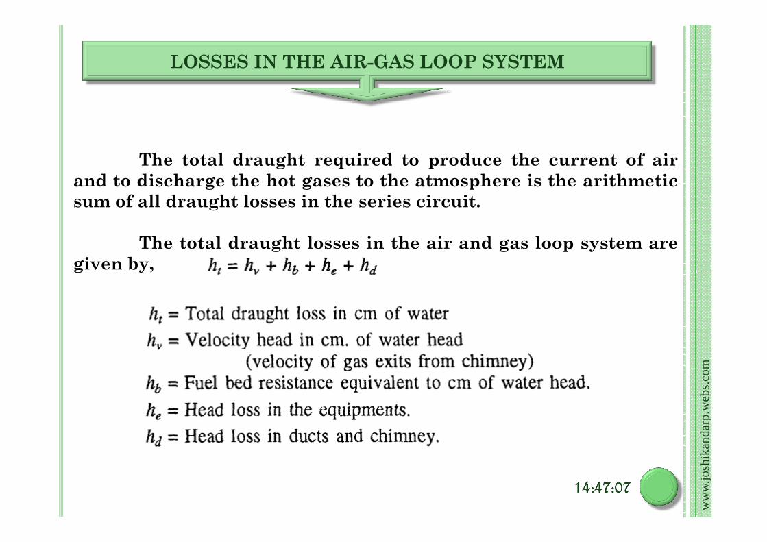
The total draught required to produce the current of air
and to discharge the hot gases to the atmosphere is the arithmetic
sum of all draught losses in the series circuit.
The total draught losses in the air and gas loop system are
given by,
ww
w.jo
shik
anda
rp.w
ebs.
com
given by,
14:47:0714:47:0714:47:0714:47:07

� Fuel Bed Resistance (hb): The fuel bed resistance depends on fuel size,
bed thickness and combustion rate. The effect of combustion rate on
resistance for different types of stokers is shown in Fig. The resistance of the
spreader stoker is not shown in figure because much of the coal is burned in
suspension. The draught resistance of spreader stoker may be taken as 6 cm
of water head.
ww
w.jo
shik
anda
rp.w
ebs.
com
14:47:0714:47:0714:47:0714:47:07

�Head Loss in Equipments (he): The manufacturers generally
supply data for equipment resistance like air heater,
economizer, boiler passes, super heaters, etc.
A survey of test data indicates that the draught losses follow a parabolic
law. the loss at another rating can be calculated by using the following
equation :
ww
w.jo
shik
anda
rp.w
ebs.
com
14:47:0714:47:0714:47:0714:47:07
equation :
where he is the draught loss at the steam generating rate of ms
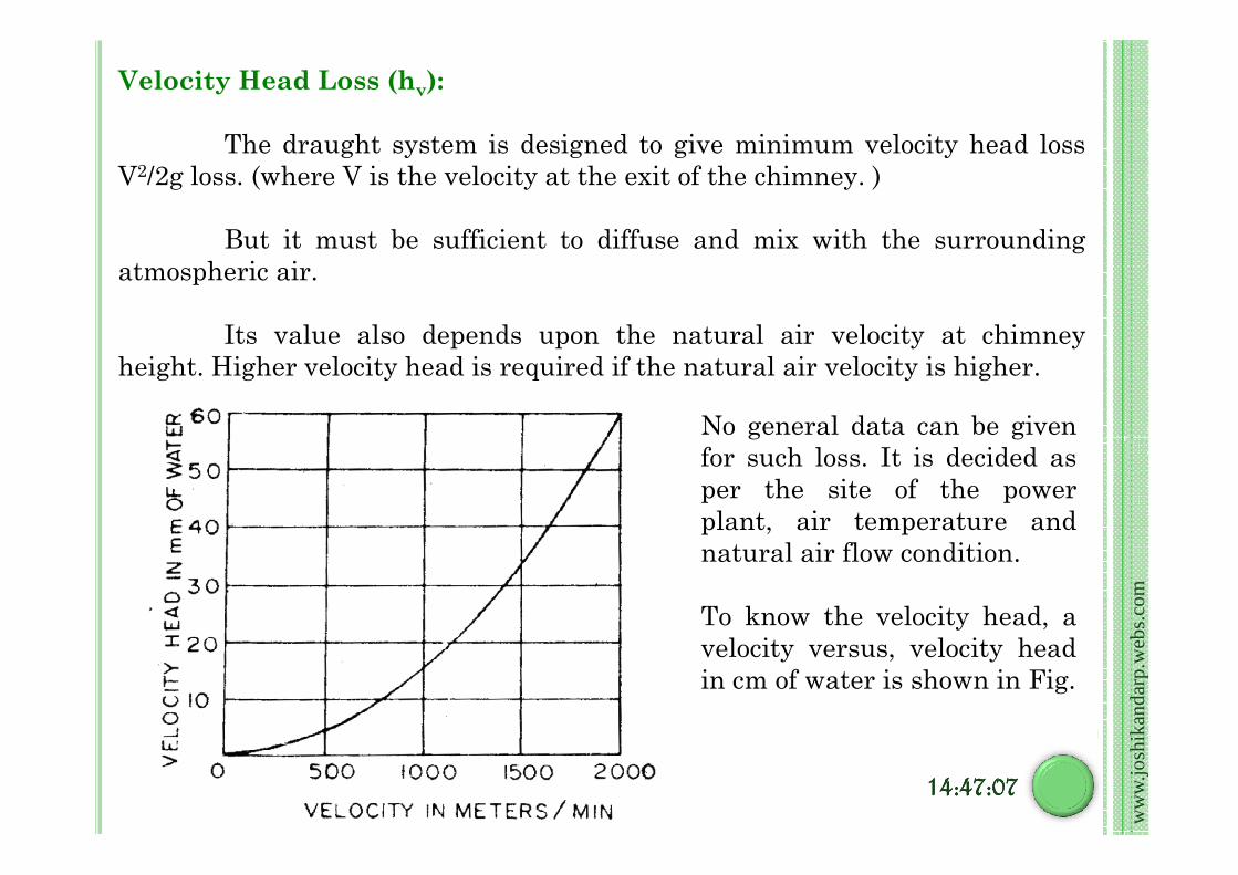
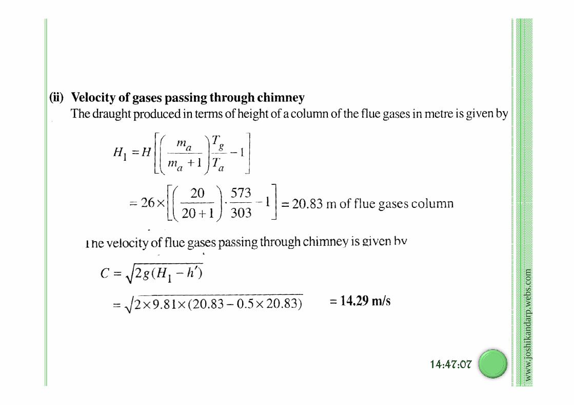
Velocity Head Loss (hv):
The draught system is designed to give minimum velocity head loss
V2/2g loss. (where V is the velocity at the exit of the chimney. )
But it must be sufficient to diffuse and mix with the surrounding
atmospheric air.
Its value also depends upon the natural air velocity at chimney
height. Higher velocity head is required if the natural air velocity is higher.
No general data can be given
ww
w.jo
shik
anda
rp.w
ebs.
com
14:47:0714:47:0714:47:0714:47:07
No general data can be given
for such loss. It is decided as
per the site of the power
plant, air temperature and
natural air flow condition.
To know the velocity head, a
velocity versus, velocity head
in cm of water is shown in Fig.
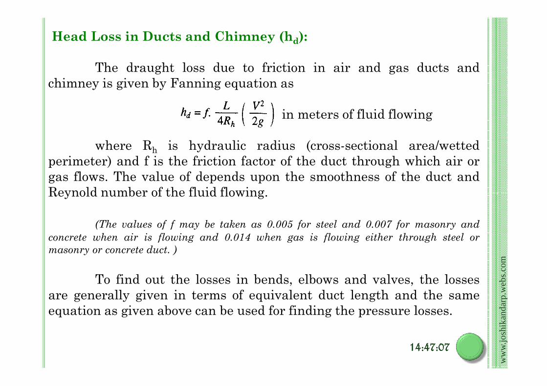
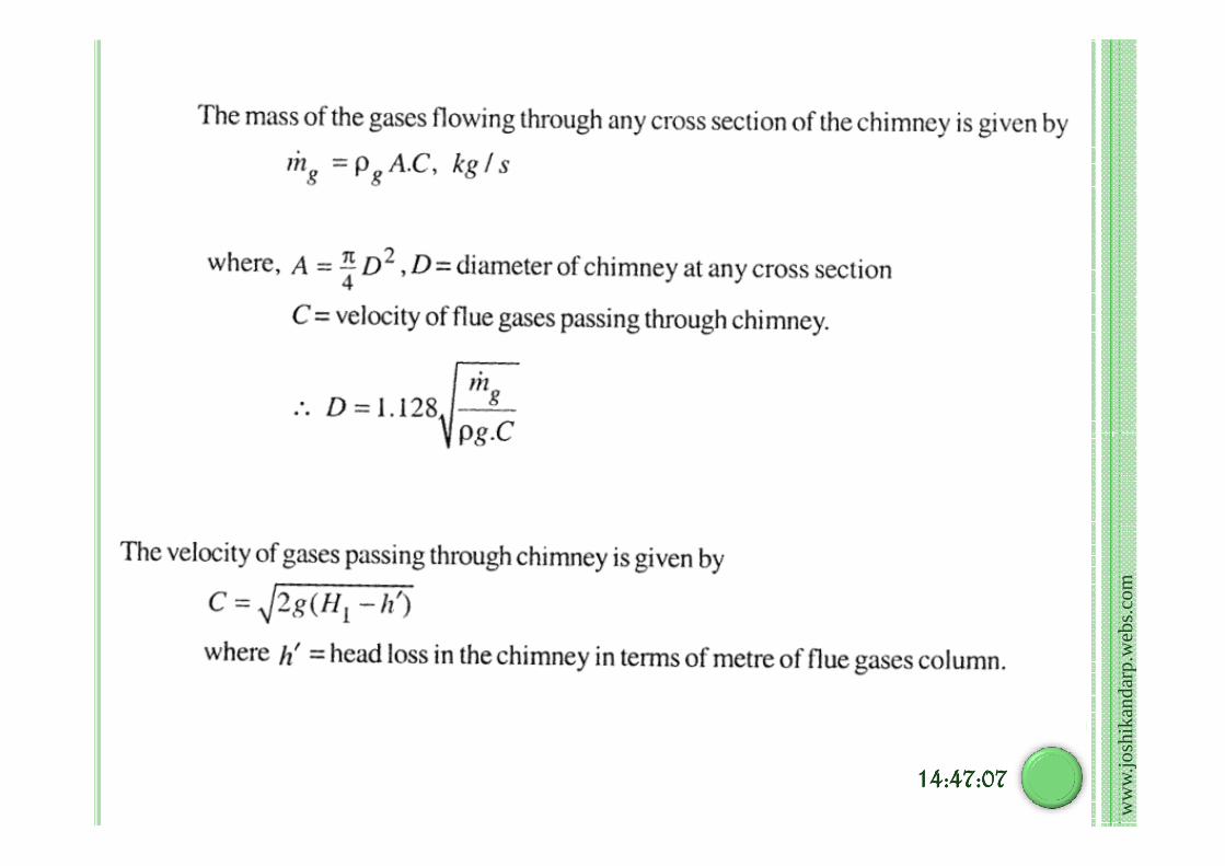
Head Loss in Ducts and Chimney (hd):
The draught loss due to friction in air and gas ducts and
chimney is given by Fanning equation as
in meters of fluid flowing
where Rh is hydraulic radius (cross-sectional area/wetted
perimeter) and f is the friction factor of the duct through which air or
gas flows. The value of depends upon the smoothness of the duct and
Reynold number of the fluid flowing.
ww
w.jo
shik
anda
rp.w
ebs.
com
14:47:0714:47:0714:47:0714:47:07
Reynold number of the fluid flowing.
(The values of f may be taken as 0.005 for steel and 0.007 for masonry and
concrete when air is flowing and 0.014 when gas is flowing either through steel or
masonry or concrete duct. )
To find out the losses in bends, elbows and valves, the losses
are generally given in terms of equivalent duct length and the same
equation as given above can be used for finding the pressure losses.

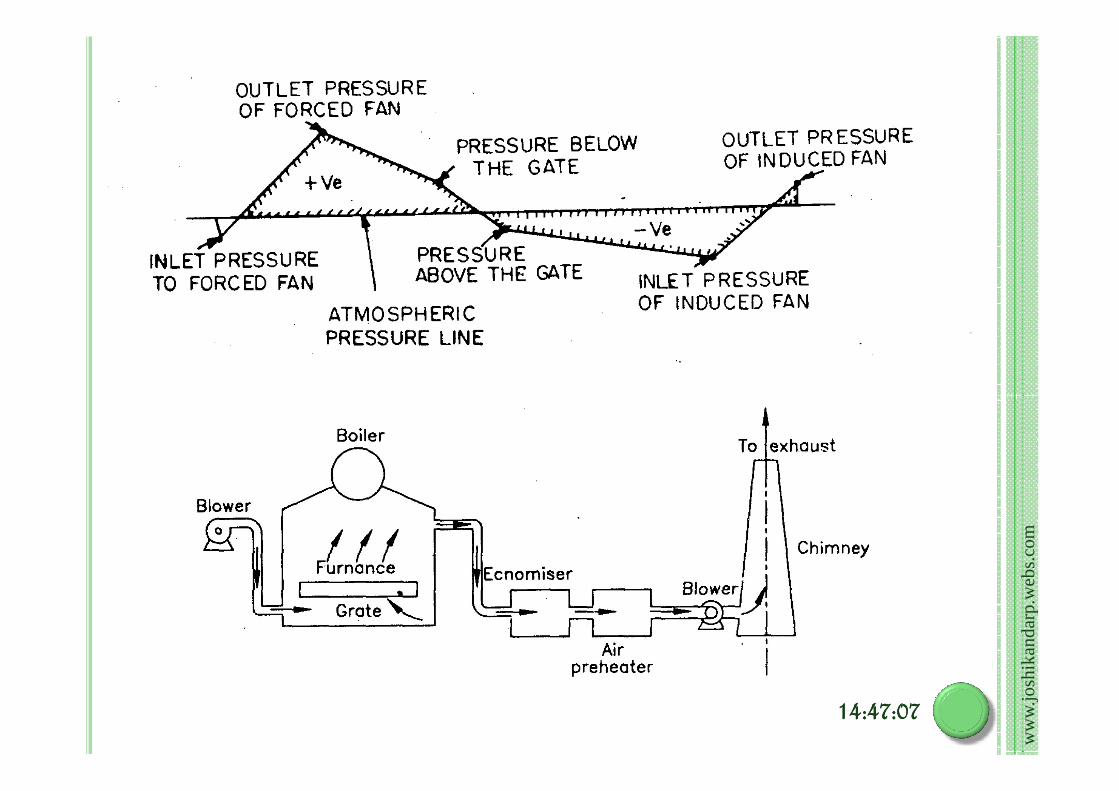
Measurement of Draught:
The draught losses in
different parts of the boiler plant
are measured in mm of water
with the help of manometers.
This pressure may be above
atmospheric pressure or below
atmospheric pressure. For very
accurate measurement, the
inclined type manometer is used.
ww
w.jo
shik
anda
rp.w
ebs.
com
inclined type manometer is used.
The typical draught at
different points of the boiler plant
measured by U-tube manometer
is shown in figure.
The measurement of
draught serves not only to find
out the resistance to the air and
gas flow but it also indicates the
rate of flow.
ADVANTAGES :
(1) It does not require any external power for producing the draught.
(2) The capital investment is less. The maintenance cost is nil as there is
no mechanical part.
(3) Chimney keeps the flue gases at a high place in the atmosphere which
prevents the contamination of atmosphere.
(4) It has long life.
Advantages and Limitations of Chimney / Natural Draught
ww
w.jo
shik
anda
rp.w
ebs.
com
14:47:0714:47:0714:47:0714:47:07
LIMITATIONS :
(1) The maximum pressure available for producing natural draught by
chimney is hardly 10 to 20 mm of water under the normal atmospheric
and flue gas temperatures.
(2) The available draught decreases with increase in outside air
temperature and for producing sufficient draught, the flue gases have
to be discharged at comparatively high temperatures resulting in the
loss of overall plant efficiency. And thus maximum utilization of Heat is
not possible.
(3) As there is no through mixing of air and fuel in the combustion chamber
due to low velocity of air therefore combustion is very poor. This
increases the specific fuel consumption.
(4) The chimney has no flexibility to create more draught under peak load
conditions because the draught available is constant for a particular
height of chimney and the draught can be increased by allowing the flue
gases to leave the combustion chamber at higher temperatures. This
reduces the overall efficiency of the plant.
ww
w.jo
shik
anda
rp.w
ebs.
com
14:47:0714:47:0714:47:0714:47:07
Nearly 20% heat released by the fuel is lost to the flue gases. The
chimney draught is only used for very small boilers. Nowadays the
chimney is never used for creating draught in thermal power plants as it
has no flexibility, the total draught produced is insufficient for high
generating capacity.
The chimney is used in all power plants only to discharge the flue
gases high in the atmosphere to maintain the cleanliness of the
surrounding atmospheric air.

Because of insufficient head and lack of flexibility,
The use of natural draught is limited to small capacity
boilers only. The draught required in actual power plant is
sufficiently high (300 mm of water) and to meet high draught
requirements, some other system must be used [known as
Why artificial draught ? ? ?
ww
w.jo
shik
anda
rp.w
ebs.
com
14:47:0714:47:0714:47:0714:47:07
requirements, some other system must be used [known as
artificial draught].
The artificial draught is more economical when the
required draught is above 40 mm of water.

In a forced draught system, a blower is installed near the base of the
boiler. This draught system is known as positive draught system or
forced draught system because the pressure of air throughout the
system is above atmospheric pressure and air is forced to flow through
the system. The arrangement of the system is shown in figure.
Force Draught
ww
w.jo
shik
anda
rp.w
ebs.
com
14141414::::47474747::::07070707
A stack or chimney is also used in this system as shown in figure but it is
not much significant for producing draught.
In this system, the blower is located near the base of the chimney
instead of near the grate. The air is sucked in the system by reducing
Induced Draught
ww
w.jo
shik
anda
rp.w
ebs.
com
14:47:0714:47:0714:47:0714:47:07
instead of near the grate. The air is sucked in the system by reducing
the pressure through the system below atmosphere.
The action of the induced draught is similar to the action of the
chimney. The draught produced is independent of the temperature of
the hot gases therefore the gases may be discharged as cold as possible
after recovering as much heat as possible in air-preheater and
economiser.

This draught is used generally when economiser and air-preheater
are incorporated in the system. The fan should be located at such a
place that the temperature of the gas handled by the fan is lowest.
The chimney is also used in this system and its function is similar as
mentioned in forced draught but total draught produced in induced
draught system is the sum of the draughts produced by the fan and
chimney. The arrangement of the system is shown in Figure.
ww
w.jo
shik
anda
rp.w
ebs.
com
14:47:0714:47:0714:47:0714:47:07
The balanced draught is a combination of forced and induced draught.
If the forced draught is used alone, then the furnace cannot be opened either
for firing or inspection because the high pressure air inside the furnace will
try to blow out suddenly and there is every chance of blowing out the fire
completely and furnace stops.
Why artificial draught ? ? ?
Balanced Draught
ww
w.jo
shik
anda
rp.w
ebs.
com
14:47:0714:47:0714:47:0714:47:07
completely and furnace stops.
If the induced draught is used alone, then also furnace cannot be opened
either for firing or inspection because the cold air will try to rush into the
furnace as the pressure inside the furnace is below atmospheric pressure.
This reduces the effective draught and dilutes the combustion.
To overcome both the difficulties mentioned above either using forced
draught or induced draught alone, a balanced draught is always preferred.
ww
w.jo
shik
anda
rp.w
ebs.
com
14:47:0714:47:0714:47:0714:47:07
Advantages of mechanical draught over
natural draught.
1. The artificial mechanical draught is better in control and more
economical than natural draught.
2. The rate of combustion is high as the available draught is more.
The better distribution and mixing of air with fuel is possible
therefore the quantity of air required per kg of fuel is less.therefore the quantity of air required per kg of fuel is less.
3. The air flow can be regulated according to the requirement by
changing the draught pressure.
4. The chimney draught is produced at the cost of thermal efficiency
of the plant because it is necessary to exhaust the gases at high
temperature to produce the draught. In mechanical draught, the
exhaust gases can be cooled to lowest possible temperature before
exhaust and improves the overall thermal efficiency of the plant.
ww
w.jo
shik
anda
rp.w
ebs.
com

5. The height of the chimney used in mechanical draught can be reduced
sufficiently as the function of the chimney is only to exhaust the gases
high in the atmosphere to prevent the contamination.
6. The efficiency of the artificial draught is nearly 7% whereas the
efficiency of the chimney draught is hardly 1%.
7. The fuel consumption per kW due to artificial draught is 15% less than
the natural draught.
8. The fuel burning capacity of the grate is 200 to 300 kg/m2 in area of
ww
w.jo
shik
anda
rp.w
ebs.
com
8. The fuel burning capacity of the grate is 200 to 300 kg/m2 in area of
the grate per hour with mechanical draught whereas it is hardly 50
kg/m2-hr with natural draught.
9. It prevents the formation of smoke as complete combustion is possible
even with less excess air.
The major disadvantage of the artificial draught is the high
capital cost required and high running and maintenance costs of the
fans used.
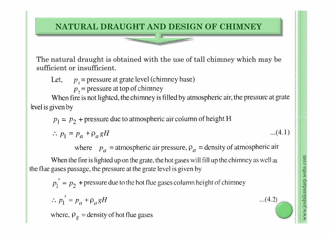
The natural draught is obtained with the use of tall chimney which may be
sufficient or insufficient.
NATURAL DRAUGHT AND DESIGN OF CHIMNEY
ww
w.jo
shik
anda
rp.w
ebs.
com
14:47:0714:47:0714:47:0714:47:07

ww
w.jo
shik
anda
rp.w
ebs.
com
14:47:0714:47:0714:47:0714:47:07
ww
w.jo
shik
anda
rp.w
ebs.
com
ww
w.jo
shik
anda
rp.w
ebs.
com
14:47:0714:47:0714:47:0714:47:07

ww
w.jo
shik
anda
rp.w
ebs.
com
14:47:0714:47:0714:47:0714:47:07

ww
w.jo
shik
anda
rp.w
ebs.
com

ww
w.jo
shik
anda
rp.w
ebs.
com
14:47:0714:47:0714:47:0714:47:07
ww
w.jo
shik
anda
rp.w
ebs.
com
14:47:0714:47:0714:47:0714:47:07

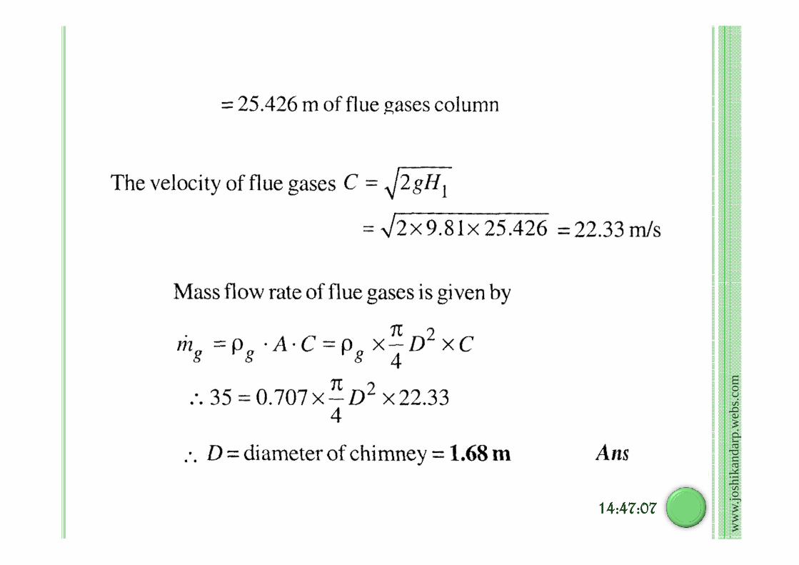
Determine height and diameter of chimney to produce
static draught of 18 mm of water column if mean flue gas
temperature and flow rate are 300 C and 2100 kg/min respectively,
the atmospheric air temperature is 25 C. The gas constant for air is
287 KJ/ Kg K. and for flue gas 250 KJ/Kg K. Assume no loss of
draught in chimney and barometer reading is 760 mm of mercury.
ww
w.jo
shik
anda
rp.w
ebs.
com

ww
w.jo
shik
anda
rp.w
ebs.
com
14:47:0714:47:0714:47:0714:47:07
ww
w.jo
shik
anda
rp.w
ebs.
com
14:47:0714:47:0714:47:0714:47:07