dramix safe concrete reinforcement for safe shotcrete structures
DESCRIPTION
Dramix reinforced concrete for safe shotcrete structures. What if you had a material that provided you with unlimited possibilities to build and develop your projects? Meet Dramix®, the proven steel fiber concept from industry specialist Bekaert, which has set a new standard for concrete reinforcement. What you get from Dramix® reinforced concrete is ductility and high load bearing capacity.TRANSCRIPT

Dramix® economic concrete reinforcement for safe floors on piles
Dramix®
Test, specify and build

FB1aFB1aFB1aFB1a
FB
1a
FB
1aF
B1f
FB
1cF
B1d
FB
1d
FB
1e
FB
1e
FB1g
FB1b
FB
2a
FB
2a
FB
2a
FB
2a
FB
2a
FB
2a
FB
2b
FB
2a
FB3a FB3b
FB4b
FB4a
FB2c
FB
5
FB6
300
30
30
afm
. ifv
. in
te
beto
nne
ren
box
3030
0
K-101
FB
1c
360 360 360 360 360 360 235
283
375
467
283
360
440
514
475
508
375
375
375
375
375
440
430
235
375
375
375
375
283
245
500 500 500 500 500
A
500
3000
B
4315
500
515
511
440
440
440
440
505
9
1'
10'10
8
7
6
5
4
3
2
1
585 600 585 560
AA
2355
25
35 85
404080
4080
4080
305
55
145
20
420
25
440
440
440
511
515
500
474
270 290 25
25
150
5
BB' BB'
645
150
150160
25
490 500 500 500 500
2598
415
13
druk (kN) aantal
122300
20300
8600
trek (kN)
100
paaltype : schroefpaal met volledige grondverdringingaantal : 150 stuks
PAALFUNDERING
LEGENDE : paalnummer
druk127/300/-100/-1,00
trek
afkappingspeil
63/300/-0,50*afkappingspeil / i.g.v. uitvoering vloerplaat : afkappingspeil ter plaatse nazien in functie van betonkwaliteit in paalkop
3
16020
75 85
330
95
180
474
25
35 85
zolen inrijhelling verankeren aan bestaande paalkoppen
bestaande paalkop
150
150
150
150
75
75
75
75
7575
7575
PK1 PK1 PK1 PK1 PK1
PK3
PK2
PK3
PK3
PK3
PK3
PK3
PK5
PK7
PK5
PK1PK4
PK3
PK1
PK1
PK1
PK1
PK1
PK1
PK1
PK6PK1PK1PK1PK1
PK : LxBxHPK1 : 200x80x80PK2 : 390x80x75PK3 : 280x80x75PK4 : 300x80x75PK5 : 60x60x60PK6 : 200x120x80PK7 : 145x120x80
DOSSIER NR : S06 0406
PLAN NR :
WIJZIGINGEN :
OPDRACHTGEVER
MOLENS TAELMANRue de Bossuit7760 POTTES
MOLENS TAELMANRue de Bossuit7760 POTTES
P. & P. SILEGHEMLeopoldstraat, 268550 ZWEVEGEM
BOUWHEER
ARCHITEKT
DATUM : 17.04.2007
LEOPOLDSTRAAT 268550 ZWEVEGEM
INGENIEURSBUREAUBVBA ARCAD BV
TEL. 056/75.86.00FAX. 056/75.77.20
MOLENS TAELMAN
BOUWEN VAN MAGAZIJNLigging : Terrain Industriel - Le long de l'EscautPOTTES
BEKISTINGSPLAN
S2b
PLAN PAALKOPPEN-BALKEN-VLOERPLAAT 1/100
WAPENINGSPLAN
WAPENING :
BETON :
BETONDEKKING :
PROFIELSTAAL :
BE 500S of DE 500BS
voor balken 3cm -- voor platen 2cm
voor beton in contact met de grond
(platen + fund.balken) : 4cm
S235
Sterkteklasse Omgevingsklasse Consistentieklasse D max
C25/30 (algemeen) C30/37 (buitentoepassingen;beton o.i. van regen en vorst)
EE2 (algemeen) EE3 (buitentoepassingen;beton o.i. van regen en vorst)
S3/F3
20mm (vloerplaten)20mm (balken & kolommen)10mm (druklaag GW)
GB:
Specificatie vlgs NBN B15-001: 2004
b
a
15-05-2007
18-04-2007
balkdoorvoeren voor riolering , aanvullingen bijlagwapening vloer
bijkomende paal nr. 151 bij leveler + DETAILtekeningen vloerplaat en funderingen
PK1
PK1
PK1
VLOERPLAAT opleg min.15 cm op wanden leveler (detail volgt)
PRINCIPEDETAIL FUNDERINGSAANZET GEVELS
RANDBALK OPLEG VLOERRANDBALK OPLEG VLOER
- BENOR-POLIERBETON 22 cm- DOORZICHTIGE PE-FOLIE 0,2mm- GESTABILISEERD ZAND 13cm
0,00
KRIMPVRIJE MORTEL
22
-0,57
+0,10
15
RANDBALK OPLEG VLOER
BETONPLINT
- BENOR-POLIERBETON 22 cm- DOORZICHTIGE PE-FOLIE 0,2mm- GESTABILISEERD ZAND 13 cm
0,00
-0,10
RANDISOLATIE PS 1cm
MAAIVELD
CELLENBETONPANEEL
VOCHTISOLERING
1322
KRIMPVRIJE MORTEL33
- POLIERBETON 22 cm , BENOR zie bestek- DOORZICHTIGE PE-FOLIE 0,2mm- GESTABILISEERD ZAND 13cm
0,00
dekking 3 cm
BOVENWAPENINGS - NETMET ONDER
AANGELASTE AFSTANDSHOUDERS
BOVENWAPENINGS - NETMET ONDER
AANGELASTE AFSTANDSHOUDERS
BOVENWAPENINGSSTAVEN2x 5st. dia.12 L=1m, à 30-40mm
OPGEBONDEN OP NET, dekking 30 mm
BOVENWAPENINGSSTAVEN2x 5st. dia.12 L=1m, à 30-40mm
OPGEBONDEN OP NET, dekking 30 mm
BOVENWAPENINGS - NET8/8/150/150 MET ONDER
AANGELASTE AFSTANDSHOUDERS
BOVENWAPENINGS - NET8/8/150/150 MET ONDER
AANGELASTE AFSTANDSHOUDERS
AS
LIJ
N V
LO
ER
PA
AL
VLOERPAALASLIJN VLOERPAAL
PLAN
PRINCIPEDETAIL VLOERPLAATBIJLEGWAPENING HOEK
PLAN
RANDISOLATIE 2 cmROND PROFIEL volgensOMHULLENDE RECHTHOEK
RANDISOLATIE 2 cmROND PROFIEL volgensOMHULLENDE RECHTHOEK
OPMERKING: ANALOOG DETAIL VOOR ANDEREOPLEGPUNTEN (OOK OP STEUNBLOKKENOP PAALKOPPEN PK 3 , ENZ.)
OPMERKING: ANALOOG DETAIL VOOR ELKEANDERE BINNENHOEK IN PLAAT WAARKERFWERKING KAN OPTREDEN (LEVELER, ENZ)
METAALPLAATJE GELASTVOLGENS OMHULLENDE VAN STAALPROFIEL
OFVOORAF OPGIETEN VANBINNENKANT PROFIEL
METAALPLAATJE GELASTVOLGENS OMHULLENDE VAN STAALPROFIEL
OFVOORAF OPGIETEN VANBINNENKANT PROFIEL
RANDISOLATIE 1 cmTUSSEN PLAAT en PLINT
RANDISOLATIE 1 cmTUSSEN PLAAT en PLINT
PRINCIPEDETAIL VLOERPLAATBIJLEGWAPENING AAN
KOLOM, BINNENHOEK, ENZ.
BETON MET TRILNAALDTE VERDICHTEN
BETON MET TRILNAALDTE VERDICHTEN
PRINCIPEDETAIL VLOERPLAATFUNDERING VLOER OP PALEN,
EA. OPLEGPUNTEN
44 4 44
4 44 4 4
DETAIL ROOSTERGOOT
±25
WATERDICHTE BETON
WATERDICHTE BETON
ROOSTERGOOT KLASSE D MET RANDVERSTERKING
VERSTERKTE DICHTING TUSSEN ROOSTERGOOT EN BETON
afh.
v/ty
pe
55 (
FB
1..)
/ 4
0 (
FB
1g)
/50
(F
B2.
.) /
60
(F
B3.
.) /
34 (
FB
4..,
5..,
6..)
50
50
100
135
150
7575
BOVENWAPENINGS - NET8/8/150/150 MET ONDER
AANGELASTE AFSTANDSHOUDERS,PERFECT OP PAAL
GECENTREERD
75 75
150
44
44
4
BOVENWAPENINGSSTAVEN2x 5st. dia.12 L=1m, à 30-40mm
OPGEBONDEN OP NET, dekking 30 mm : ZIE BOVENAANZICHT
BOVENWAPENINGSSTAVEN2x 5st. dia.12 L=1m, à 30-40mm
OPGEBONDEN OP NET, dekking 30 mm : ZIE BOVENAANZICHT
100
100
INTRODUCTION
My aim is to familiarize the reader with the behaviour of steel fibre reinforced conrete, to draw his attention to the specific characteristics of this product, the importance of the performance described by the EN standard and propose a relevant technical solution to reach together a better quality and safety on each job site.
This brochure is meant primarily for those who are active in the construction market (investors, contractors, designers) and more specially in the field of industrial floors.
Initially, floors were applied either plainly or reinforced with conventional reinforcing steel welded meshes. It was, however, only in the early seventies that the first experimental work was undertaken with Steel Fibre Reinforced Concrete (SFRC).
SFRC is defined as concrete, containing discontinuous steel fibres, which are homogeneously mixed into the concrete.
Since then, SFRC has been used extensively in most of the world’s industrialized nations, for a wide variety of applications. Uses of SFRC in industrial floor applications vary from traditional saw cut floors, over jointless floors, and to most structural floor on pile application.
Multiple research studies and tests on the behaviour of steel fibre reinforced concrete have been carried out in recent years in various countries. They have greatly contributed to a better characterization and understanding of the behaviour of this material. They have also contributed to the specification of minimum performance requirements for each type of application.
During the period 2003 – 2007, a Dutch expert commission focused on the materials, test methods, design principles and execution controls for pile supported steel fibre floors. This has resulted in the CUR 111 recommendation document.
Table of contents
03040409101212131314
IntroductionApplication fieldMaterialsSystem performance, calculation of MdCalculation of MuPunchingExecution detailsQuality examinationsStandard specification textBibliography
Anne HoekstraTechnical Manager Flooring

1. APPLICATION FIELD
This document discusses test methods, design and execution for a pile – suspended concrete industrial floor, reinforced with Dramix® steel fibres.
This guideline can only be used for:
- Industrial floors and not for other applications, such as pile-suspended rafts for residential or other use.- Dramix® steel fibre reinforcement, and not for other steel fibres, synthetic fibres or traditional mesh reinforcement.
2. MATERIALS
2.1. Concrete:
Concrete quality in accordance with EN 206, produced and delivered according to local concrete standards:- Minimum Concrete Quality: C20/25- Maximum Concrete Quality: C30/37
The grading of aggregates will be in accordance with the applicable standards. The concrete composition must be engineered in order to obtain homogeneous distribution and good finish ability. For detailed information, consult our product data sheets and our recommendations on handling, dosing and mixing.
2.2. Steel fibres:
Dramix® steel fibres are designed especially for the reinforcement of concrete. They are made of prime qualityhard-drawn steel wire to ensure high tensile strength at extremely close tolerances.Provided with hooked ends, they deliver optimum anchorage.
Minimum fibre requirements are:
Fibres with CE- marking system 1, steel fibre for structural use (conform EN 14889-1-2006) For detailed info, please request our CE info sheet.
Fibres out of drawn wire, with a tensile strength of steel wire > 1000 MPa min.
Dimensional tolerances in accordance with EN 14889-1.
Best anchorage system : hooked ends for optimum anchorage.
Minimum fibre length : 2 times the maximum coarse aggregate size.
Maximum fibre length : 2/3 of the hose diameter of the pumping machine.
Glued fibres for improved and risk-free pump ability and mixing.
Depending on the design results,the recommended fibre types are:
Dramix® RC-65/60-BN: Dramix® Easy Mix Dramix® Hi Perform
Dramix® RC-80/60-BN: Dramix® Hi Perform
Specific product data sheets are available on request
2.3. Steel fibre reinforced concrete:
The performance of a Dramix® reinforced concrete is mainly determined by following characteristics:
- The performance of the fibre in the matrix (geometry, length/diameter ratio, method of anchorage, tensile strength,…)- The performance of the concrete matrix- The amount of fibres in the mix
2.3.1. Minimum dosage based on minimum overlap:
Minimum fibre overlap:
For structurally designed applications, the average distance between steel fibres (s) should be lower than 0,4 lf in order to ensure a minimum overlap between fibres.
s = 3 π x d f2 x lf
4ρf
Where : - lf is the length of the fibre - df is the equivalent diameter of the fibre - ρf is the fibre percentage
s should be lower than 0,4 lf to ensure a minimum overlap
The formula and “s” limits are taken from the thesis of D.C Mc Kee, University of Illinois, Urbana 1969:“The properties of an expansive mortar reinforced with random wire fibres.”
1 According to EN 14889, a minimum performance level must be reached. As such for every fibre type a minimum dosage is required to have CE marking system 1.
Download info sheet at:www.bekaert.com/building
CE info sheet
2
3
4
5
6
7
CE info sheet
Want to know more about:- Product characteristics- Approvals- Features and benefits- How to use
Download info sheets at:www.bekaert.com/building
In order to define the steel fibre concrete specification, a three steps analysis must be made.
Minimum dosage for a needed fibre overlap. Minimum total fibre length.
Dosage based on performance.
1
2
3
54
Minimum dosages of steel fibres based on different aspect ratios and steel fibre spacing
2.3.2. Minimum dosage based on minimum total fibre length:
In addition to the requirement of the minimum fibre overlap, Bekaert recommends a minimum steel fibre length of 6700 meter/m³ concrete. This fibre length ensures the minimum network effect to provide a specific multi-crackprocess and so the redistribution of the loads through the crack-bridging steel.
Example to reach three criteria: CE-minimum performance level, Mc Kee “2.3.1.” & minimum total fibre length “2.3.2.”
The crack patterns observed on different tests explain the importance of the total fibre network.
Low fibre network High fibre network: multiple cracking
section AA
A250
500
detail A
25025 25 150
FA
7575
F
δ δ1
δ
150
δII
150
30
30
25+1
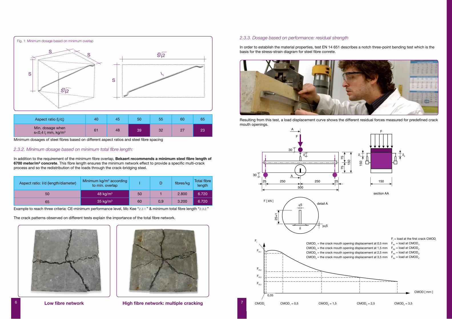
2.3.3. Dosage based on performance: residual strength
In order to establish the material properties, test EN 14 651 describes a notch three-point bending test which is the basis for the stress-strain diagram for steel fibre conrete.
Resulting from this test, a load displacement curve shows the different residual forces measured for predefined crack mouth openings.
F kNF1
FR,1
FR,2
0,05
FR,3
FR,4
CMODL CMOD1 = 0.5 CMOD2 = 1.5 CMOD3 = 2.5 CMOD4 = 3.5
CMOD mm
CMOD1 = the crack mouth opening displacement at 0,5 mm
CMOD2 = the crack mouth opening displacement at 1,5 mm
CMOD3 = the crack mouth opening displacement at 2,5 mm
CMOD4 = the crack mouth opening displacement at 3,5 mm
Fl = load at the first crack CMODl
FR1 = load at CMOD1.
FR2 = load at CMOD2.
FR3 = load at CMOD3.
FR4 = load at CMOD4.
CMODL CMOD1 = 0,5 CMOD2 = 1,5 CMOD3 = 2,5 CMOD4 = 3,5
0,05CMOD [ mm ]
FR,1
FR,2
FR,3
FR,4
Fl
F [ kN ]
Fig. 1: Minimum dosage based on minimum overlap
S
SS
Sl f
Min. dosage whens<0,4 lf mm, kg/m3
40 45 50 55 60 65
61 48 39 32 27 23
Aspect ratio (lf/df)
Aspect ratio: I/d (length/diameter)
50
Minimum kg/m3 accordingto min. overlap
I D fibres/kgTotal fibre
length
50
60
1
0,9 3.200 6.720
2.800 6.72048 kg/m3
35 kg/m365
S 2
S 2
6 7

Based on this test, the absolute minimum residual flexural tensile strength is:
f(r1) = 4,1 N/mm² f(r4) = 3,1 N/mm²
minimum residual flexural tensile strength for a C30/37 concrete
These values are proposed for a concrete class C30/37, usually specified for a pile-supported floor.Compressive strengths with a too low or too high strength class may have undesired side effects.Please contact your local Bekaert representative in order to get the minimum residual values for other concrete classes.
For the same concrete matrix, the performance level is significantly influenced by the fibre type (e.g. the anchorage type, the aspect ratio (length to diameter) and the fibre dosage. The higher the aspect ratio and fibre content,the better the performance of the SFRC.
Why use the EN 14 651 beam test method and not a round indeterminate plate test:
To determine the performance of SFRC for a floor application, the beam test is much more appropriate than a round indeterminate plate test.
Technical Report TR63 “Guidance for the design of Steel-Fibre-Reinforced concrete” outlines that round indeterminate plate tests are not covered by standards and are not a suitable method to determine the fundamental properties of SFRC. In a statically indeterminate plate test, the flexural resistance is not related to the crack width. Results of round plate tests are interpreted using yield line analysis in which the flexural resistance is assumed to be constant along the yield lines. In reality, the pattern of yield lines varies very much, and so too the crack width along these yield lines. Therefore the flexural resistance derived from statically indeterminate plate tests depends heavily on assumptions made in the analysis.
The structural response should be predicted from rigorous material models rather than the other way around.
The yield lines formed - as well as the total yield line length - in the system test set-up, significantly vary a lot over different test results and can therefore not be used to derive a uniform flexural resistance value.
Why yield-line theory should not be used:
No information is given on support reactions or deflections.
The adverse effects of pattern loading, such as uplift at piles, are not considered.
The design may be unsafe if not all the critical mechanisms have been investigated.
The method is only valid when slabs have adequate ductility for the assumed yield lines to develop. It is not possible to verify whether this is the case since the analysis provides no information on slab deformations.
Calculating the bending moments has to be done with the real pile distances. Decreasing “the design center to center distance” with the pile and/or floor thickness is not allowed.
1
2
3
4
1
2
3
4
5
2.4. Additional mesh or rebar:
The yield stress of the reinforcement is 500 N/mm2. When different, the design must be adapted in line with local standards.
3. SYSTEM PERFORMANCE CALCULATION OF Md
3.1. Minimum design information:
- Floor layout- Pile or pile head dimensions- Spans between piles in x and y direction- Floor loads- The edge of the floor field: line or point supported
3.2. Loads:
Design is made for various load situations
- Floor completely and fully loaded- Fields loaded - unloaded load case maximum bending moments to be calculated on top and bottom- Point and wheel loads
- Restrained shrinkage
}
8 9

15
Calculating of the additional reinforcement:The maximum allowable bending moment in steel fibre concrete is calculated by a cross-sectional equilibrium.The stress-strain relation conform EN 14651.
stress
fcd
fftd. 3fftd. 2fftd. 1
compression
strain
tensile
0.1‰
25‰
3.5‰1.75‰
εt,2
εc,1 εc,2
Stress-strain diagram
In this: ffcd = design value of the compressive strength.
fftd,1 = design value of the tensile strength of SFRC.
fftd,2 = design value of the tensile strength at CMOD = 0,5mm0,45 * FR1
fftd,2 = ——————γm
fftd,3 = design value of the tensile strength at CMOD = 3,5mm0,37 * FR4
fftd,3 = —————γm
In view of the relatively small contribution of fftd,1, to the bending moment resistance, it is justified to use the relation shown in the next figure.
stress
fcd
fftd. 3fftd. 2
compression
strain
tensile
25‰
3.5‰1.75‰εc,1 εc,2
Simplified stress-strain
Variant 1 : Nkrimp = 0,75 ε' Eff .h and Mkrimp = Ef . Ifloor .Κkrimp
Variant 2 : Nkrimp = ε'f, Ef.h
Unity check:
Mrep + Mkrimp NkrimpVariant 1 : —————— + ————— ≤ 1
Mwmax b.h.ft,rep,i
Mrep NkrimpVariant 2 : –––––––––– + –––––––––– ≤1
Mwmax b.h.ft,rep,i
Restrained shrinkage:
4. CALCULATION OF Mu
In each cross section Md ≤ Mu
The maximum allowable bending moment in steel fibre concrete Msfrc is calculated by a cross-sectional equilibrium. The stress-strain relation conforms to EN 14651.
In a floor construction, yield lines must be developed and this aspect of behaviour will not occur in a notched beam, where we have only one crack. The EN 14651 test does not reflect multiple cracking.And for this reason, it is allowed to calculate with mean values.
Consequently the CUR 111 clearly expresses:
“The mean (uni-axial) tensile strength is used as the starting value since the redistribution capacity of steel fibrereinforced concrete industrial floors founded on piles, also regarding the minimum fibre content, is such that the use of the mean value of the uni-axial tensile strength as a basis for design is accepted, rather than the characteristic lower limit value.”
15
Calculating of the additional reinforcement:The maximum allowable bending moment in steel fibre concrete is calculated by a cross-sectional equilibrium.The stress-strain relation conform EN 14651.
stress
fcd
fftd. 3fftd. 2fftd. 1
compression
strain
tensile
0.1‰
25‰
3.5‰1.75‰
εt,2
εc,1 εc,2
Stress-strain diagram
In this: ffcd = design value of the compressive strength.
fftd,1 = design value of the tensile strength of SFRC.
fftd,2 = design value of the tensile strength at CMOD = 0,5mm0,45 * FR1
fftd,2 = ——————γm
fftd,3 = design value of the tensile strength at CMOD = 3,5mm0,37 * FR4
fftd,3 = —————γm
In view of the relatively small contribution of fftd,1, to the bending moment resistance, it is justified to use the relation shown in the next figure.
stress
fcd
fftd. 3fftd. 2
compression
strain
tensile
25‰
3.5‰1.75‰εc,1 εc,2
Simplified stress-strain
In this:
fcd = design value of the compressive strength
fftd,1 = tensile strength design value of SFRC
fftd,2 = tensile strength design value at CMOD = 0,5 mm
fftd,2 =
fftd,3 = tensile strength design value at CMOD = 3,5 mm
fftd,3 =
0,45 * FR1
γm
0,37 * FR4
γm
Variant 1 : Nkrimp = 0,75 ε' Eff .h and Mkrimp = Ef . Ifloor .Κkrimp
Variant 2 : Nkrimp = ε'f, Ef.h
Unity check:
Mrep + Mkrimp NkrimpVariant 1 : —————— + ————— ≤ 1
Mwmax b.h.ft,rep,i
Mrep NkrimpVariant 2 : –––––––––– + –––––––––– ≤1
Mwmax b.h.ft,rep,i
16
ffcd
fftd ,2
fftd,2 (fftd,2 - fftd,3)=
+
+
-N17/18.hxu
1/3(h-hxu) 1/2(h-hxu)
hxu
d
h
Mu
T2,2
T2,1
T1
As
εc,1 = 1,75‰
εs
εft
εc,2 = 3,5 ‰
ε ft
25.10-3
Cross-sectional equilibrium
If Md>Msvb then
Mreinforcement > Md-MSFRC
The amount of reinforcement is calculated in the normal way.
Formulae:
N1 = 0.75hxubffcdd - hxuT1 = Asσs = AsEsεs = AsEs ( ——— ) 3.5.10-3 < Asfsy
hxuεft
T2,1 = b(h-hxu)(fftd,2 - ——— (fftd,2 - fftd,3))25.10-3
1 εftT2,2 = — b(h-hxu) ———— (fftd,2-fftd,3)2 25.10-3
Horizontal equilibrium:∑ H = 0 : N1 = T1 + T1,2 +T2,2
Bending moment equilibrium:11 1 1
Mu = —— hxu N1 + —— (h-hxu)T2,1 + — (h-hxu) T2,2 + (d-hxu) T118 2 3
The below diagram illustrates the theory and contains the equations based on cross-sectional equilibrium for a specifically assumed strain distribution over the height of the cross-section.
d-hxu
hxuεft
25.10-3
εft
25.10-3
1118
12
13
12
In view of the relatively small contribution of f ftd,1 to the bending moment resistance, it is justified to use the relation shown in the next figure.
The below diagram illustrates the theory and contains the equations based on cross-sectional equilibrium for a spe-cifically assumed strain distribution over the height of the cross section.
Formulae:
N1 = 0,75 hxub ffcd
T1 = Asσs = AsEsεs = AsEs ( ) 3,5.10-3 < Asfsy
T2,1 = b (h-hxu)(fftd,2 - (fftd,2 - fftd,3))
T2,2 = b (h-hxu) (fftd,2- fftd,3))
Horizontal equilibrium: ∑ H = 0 : N1 = T1 + T1,2 + T 2,2
Bending moment equilibrium: Mu = hxu N1 + (h-hxu) T2,1 + (h,hxu) T2,2 + (d-hxu) T1
If Md > Msvb then Mreinforcement ≥ Md- MSFRC
The amount of reinforcement is calculated in the normal way
10 11

5. PUNCHING
For the most critical areas for punching - around columns and piles - crack openings have to be limited in order to have sufficient shear resistance through the concrete section. Therefore, a basic traditional upper reinforcement (mesh or rebar) always needs to be applied.
When longitudinal reinforcement bars are provided, CUR 111 allows the contribution of concrete and steel fibres in the total shear stress resistance.On the other hand, the CUR recommendation clearly describes that a fibre only floor can not be designed using the fibres in the punching shear resistance.
Punching check has to be done based on the codes.There is no agreed method for calculating the designed shear strength of fibre reinforced concrete without conventional reinforcement.
It is necessary to limit crack widths in the punching area. In case of a too big crack width, the shear resistance capacity will decrease. It is only possible to realistically calculate crack widths in statically indeterminate structures without conventional reinforcement by carrying out a non-linear analysis, which is impractical for design.
The maximum crack opening is a direct consequence of the total fibre network. It is prohibited to use fibre dosages lower than the minimum dosage based on the total fibre length.See “2.3.2. Minimum dosage based on minimum total fibre length”
FB1aFB1aFB1aFB1a
FB
1a
FB
1aF
B1f
FB
1cF
B1d
FB
1d
FB
1e
FB
1e
FB1g
FB1b
FB
2a
FB
2a
FB
2a
FB
2a
FB
2a
FB
2a
FB
2b
FB
2a
FB3a FB3b
FB4b
FB4a
FB2c
FB
5
FB6
300
30
30
afm
. ifv
. in
te
beto
nne
ren
box
3030
0
K-101
FB
1c
360 360 360 360 360 360 235
283
375
467
283
360
440
514
475
508
375
375
375
375
375
440
430
235
375
375
375
375
283
245
500 500 500 500 500
A
500
3000
B
4315
500
515
511
440
440
440
440
505
9
1'
10'10
8
7
6
5
4
3
2
1
585 600 585 560
AA
2355
25
35 85
404080
4080
4080
305
55
145
20
420
25
440
440
440
511
515
500
474
270 290 25
25
150
5
BB' BB'
645
150
150160
25
490 500 500 500 500
2598
415
13
druk (kN) aantal
122300
20300
8600
trek (kN)
100
paaltype : schroefpaal met volledige grondverdringingaantal : 150 stuks
PAALFUNDERING
LEGENDE : paalnummer
druk127/300/-100/-1,00
trek
afkappingspeil
63/300/-0,50*afkappingspeil / i.g.v. uitvoering vloerplaat : afkappingspeil ter plaatse nazien in functie van betonkwaliteit in paalkop
3
16020
75 85
330
95
180
474
25
35 85
zolen inrijhelling verankeren aan bestaande paalkoppen
bestaande paalkop
150
150
150
150
75
75
75
75
7575
7575
PK1 PK1 PK1 PK1 PK1
PK3
PK2
PK3
PK3
PK3
PK3
PK3
PK5
PK7
PK5
PK1PK4
PK3
PK1
PK1
PK1
PK1
PK1
PK1
PK1
PK6PK1PK1PK1PK1
PK : LxBxHPK1 : 200x80x80PK2 : 390x80x75PK3 : 280x80x75PK4 : 300x80x75PK5 : 60x60x60PK6 : 200x120x80PK7 : 145x120x80
DOSSIER NR : S06 0406
PLAN NR :
WIJZIGINGEN :
OPDRACHTGEVER
MOLENS TAELMANRue de Bossuit7760 POTTES
MOLENS TAELMANRue de Bossuit7760 POTTES
P. & P. SILEGHEMLeopoldstraat, 268550 ZWEVEGEM
BOUWHEER
ARCHITEKT
DATUM : 17.04.2007
LEOPOLDSTRAAT 268550 ZWEVEGEM
INGENIEURSBUREAUBVBA ARCAD BV
TEL. 056/75.86.00FAX. 056/75.77.20
MOLENS TAELMAN
BOUWEN VAN MAGAZIJNLigging : Terrain Industriel - Le long de l'EscautPOTTES
BEKISTINGSPLAN
S2b
PLAN PAALKOPPEN-BALKEN-VLOERPLAAT 1/100
WAPENINGSPLAN
WAPENING :
BETON :
BETONDEKKING :
PROFIELSTAAL :
BE 500S of DE 500BS
voor balken 3cm -- voor platen 2cm
voor beton in contact met de grond
(platen + fund.balken) : 4cm
S235
Sterkteklasse Omgevingsklasse Consistentieklasse D max
C25/30 (algemeen) C30/37 (buitentoepassingen;beton o.i. van regen en vorst)
EE2 (algemeen) EE3 (buitentoepassingen;beton o.i. van regen en vorst)
S3/F3
20mm (vloerplaten)20mm (balken & kolommen)10mm (druklaag GW)
GB:
Specificatie vlgs NBN B15-001: 2004
b
a
15-05-2007
18-04-2007
balkdoorvoeren voor riolering , aanvullingen bijlagwapening vloer
bijkomende paal nr. 151 bij leveler + DETAILtekeningen vloerplaat en funderingen
PK1
PK1
PK1
VLOERPLAAT opleg min.15 cm op wanden leveler (detail volgt)
PRINCIPEDETAIL FUNDERINGSAANZET GEVELS
RANDBALK OPLEG VLOERRANDBALK OPLEG VLOER
- BENOR-POLIERBETON 22 cm- DOORZICHTIGE PE-FOLIE 0,2mm- GESTABILISEERD ZAND 13cm
0,00
KRIMPVRIJE MORTEL
22
-0,57
+0,10
15
RANDBALK OPLEG VLOER
BETONPLINT
- BENOR-POLIERBETON 22 cm- DOORZICHTIGE PE-FOLIE 0,2mm- GESTABILISEERD ZAND 13 cm
0,00
-0,10
RANDISOLATIE PS 1cm
MAAIVELD
CELLENBETONPANEEL
VOCHTISOLERING
1322
KRIMPVRIJE MORTEL33
- POLIERBETON 22 cm , BENOR zie bestek- DOORZICHTIGE PE-FOLIE 0,2mm- GESTABILISEERD ZAND 13cm
0,00
dekking 3 cm
BOVENWAPENINGS - NETMET ONDER
AANGELASTE AFSTANDSHOUDERS
BOVENWAPENINGS - NETMET ONDER
AANGELASTE AFSTANDSHOUDERS
BOVENWAPENINGSSTAVEN2x 5st. dia.12 L=1m, à 30-40mm
OPGEBONDEN OP NET, dekking 30 mm
BOVENWAPENINGSSTAVEN2x 5st. dia.12 L=1m, à 30-40mm
OPGEBONDEN OP NET, dekking 30 mm
BOVENWAPENINGS - NET8/8/150/150 MET ONDER
AANGELASTE AFSTANDSHOUDERS
BOVENWAPENINGS - NET8/8/150/150 MET ONDER
AANGELASTE AFSTANDSHOUDERS
AS
LIJ
N V
LO
ER
PA
AL
VLOERPAALASLIJN VLOERPAAL
PLAN
PRINCIPEDETAIL VLOERPLAATBIJLEGWAPENING HOEK
PLAN
RANDISOLATIE 2 cmROND PROFIEL volgensOMHULLENDE RECHTHOEK
RANDISOLATIE 2 cmROND PROFIEL volgensOMHULLENDE RECHTHOEK
OPMERKING: ANALOOG DETAIL VOOR ANDEREOPLEGPUNTEN (OOK OP STEUNBLOKKENOP PAALKOPPEN PK 3 , ENZ.)
OPMERKING: ANALOOG DETAIL VOOR ELKEANDERE BINNENHOEK IN PLAAT WAARKERFWERKING KAN OPTREDEN (LEVELER, ENZ)
METAALPLAATJE GELASTVOLGENS OMHULLENDE VAN STAALPROFIEL
OFVOORAF OPGIETEN VANBINNENKANT PROFIEL
METAALPLAATJE GELASTVOLGENS OMHULLENDE VAN STAALPROFIEL
OFVOORAF OPGIETEN VANBINNENKANT PROFIEL
RANDISOLATIE 1 cmTUSSEN PLAAT en PLINT
RANDISOLATIE 1 cmTUSSEN PLAAT en PLINT
PRINCIPEDETAIL VLOERPLAATBIJLEGWAPENING AAN
KOLOM, BINNENHOEK, ENZ.
BETON MET TRILNAALDTE VERDICHTEN
BETON MET TRILNAALDTE VERDICHTEN
PRINCIPEDETAIL VLOERPLAATFUNDERING VLOER OP PALEN,
EA. OPLEGPUNTEN
44 4 44
4 44 4 4
DETAIL ROOSTERGOOT
±25
WATERDICHTE BETON
WATERDICHTE BETON
ROOSTERGOOT KLASSE D MET RANDVERSTERKING
VERSTERKTE DICHTING TUSSEN ROOSTERGOOT EN BETON
afh.
v/ty
pe
55 (
FB
1..)
/ 4
0 (
FB
1g)
/50
(F
B2.
.) /
60
(F
B3.
.) /
34 (
FB
4..,
5..,
6..)
50
50
100
135
150
7575
BOVENWAPENINGS - NET8/8/150/150 MET ONDER
AANGELASTE AFSTANDSHOUDERS,PERFECT OP PAAL
GECENTREERD
75 75
150
44
44
4
BOVENWAPENINGSSTAVEN2x 5st. dia.12 L=1m, à 30-40mm
OPGEBONDEN OP NET, dekking 30 mm : ZIE BOVENAANZICHT
BOVENWAPENINGSSTAVEN2x 5st. dia.12 L=1m, à 30-40mm
OPGEBONDEN OP NET, dekking 30 mm : ZIE BOVENAANZICHT
100
100
Concrete cover
Concrete floorPE plastic sheetSoil
7. QUALITY EXAMINATIONS
Your Bekaert local specialist can support you with a comprehensive quality control program.
Generals: - Check the top level of all piles and foundations beams. These must be below the bottom of the concrete floor to allow casting.- Check the level of the subbase. must be leveled to +0 ; - 20 mm of the bottom of the concrete floor.- Check whether the plastic sheet is placed correctly, with enough overlap and fixed in such a way that the sheet will not curl up during the casting of the steel fibre concrete.
Must be in line with the Bekaert detailed drawings: - The extra reinforcement is placed. The top and bottom reinforcement need enough support to hold it in place during the concrete casting process. - The reinforcement concrete cover. - The joint profiles are positioned and oriented correctly.
- The concrete mix needs to be designed and adapted in such a way that Dramix® fibres can be mixed easily and a good concrete workability is obtained. Moreover, the maximum water/cement ratio is 0,5. Contact your local Bekaert specialist for optimal steel fibre concrete recepies.
Must be in line with the Bekaert design: - The concrete thickness during casting. - The right fibre type is used. - The fibre dosage: check through several washing out tests (when an automatic dosing machine is not applied)
- If needed: start up a quality program with beam tests, produced in accordance with the EN 14 651 in order to control the performance. Our concrete lab is an open door for jobsite test programs. Contact your Bekaert specialist.
6. EXECUTION DETAILS
Depending on the specific project circumstances,specific execution details (joint profiles,special reinforcement,…) have to be applied.For your tailor-made job site details,please contact your local Bekaert specialist.
Benefit from our total design management:- Joint profiles- Reinforcement details- Concrete compositonContact your local bekaert specialist or: [email protected]
Execution details
8. STANDARD SPECIFICATION TEXT
Fibres - Fibres to comply with European Standard EN 14 889-1. - Fibres with CE-marking system 1. Fibres out of drawn wire, with a tensile strength of steel wire > 1.000 Mpa min. Dimensional tolerances according to CE. - Minimum fibre length : 2 times the maximum coarse aggregate size. - Maximum fibre length : 2/3 of the hose diameter of the pumping machine.
Performance - Minimum total wire length/m³ should be 6.700 meter in order to ensure the minimum network effect. - Minimum fibre overlap according to Mc Kee Theory. - Residual flexural tensile strength in accordance with the design, but as absolute minimum. f(r1) = 4,1 N/mm² f(r4) = 3,1 N/mm² - Concrete quality and additional reinforcement in accordance with design note.
Fibre concrete - Glued fibres for improved and risk – free pumpability and mixing. - It is prohibited to use loose steel fibres which will cause balls during mixing.
Download at: www.bekaert.com/building
1
2
3
Fig. 2: Pile head detail
12 13

9. BIBLIOGRAPHY
- EN 206-1: Concrete – Part 1: Specification, performance, production and conformity.
- EN 12390-3: 2002 Testing Hardened concrete – Part 3: Compressive strength of test specimens
- EN 14651: 2005 Test method for metallic fibre concrete
- EN 14889-1: 2006 Fibres in concrete – part 1: Steel fibres Definitions, specifications and conformity
- NEN 2743: 2003: In situ floorings – execution of monolithic screeds and paving
- NEN 2747: 2001 Classification and measuring of the flatness and parallelism of the surface of floorings
- NEN 6700: 2005: Technical principles for building structures TGB 1990 – general principles
- NEN 6702: 2002: Regulations for concrete Loadings and deformations
- NEN 6720: 1995: Regulations for concrete – structural requirements and calculation methods, incl. Amendments documents
- NEN 6722: 2002: Regulations for concrete – Construction
- Technical report n°63: Guidance for the design of Steel-Fibre-Reinforced concrete
- CUR-Recommendation 111: Steel-Fibre-Reinforced concrete industrial floors on pile foundations - design and construction
14 15

NV Bekaert SA
Bekaertstraat 2
BE-8550 Zwevegem
Belgium
www.bekaert.com/building
Customer service:
T +32 56 76 61 10
F +32 56 76 79 47 des
ign
by
BO
A-i
nc.b
e -
52.2
5.05
Modifications reserved. All details describe our products and solutions in
general form only. For ordering and design only use official specifications
and documents.
© 2009 Bekaert
ABOUT BEKAERT
Bekaert is active worldwide in selected applications of its two core competences: advanced metal transformation and advanced materials and coatings. The combination of these competences makes Bekaert very unique.Bekaert, headquartered in Belgium, is a technological leader and serves a worldwide customer base in a variety of industry sectors.
BUILDING WITH BEKAERT
Bekaert products are widely used in the construction sector. Dramix® has given Bekaert a leading position in the market of steel fibre concrete reinforcement. In 1979, Bekaert introduced Dramix® steel fibres for concrete reinforcement, designed to offer an easy-to-use alternative for traditional steel mesh and bar reinforcement. Applications of Dramix® steel fibres include industrial floors, precast elements, tunneling and mining, residential applications and public works.
Other Bekaert building products • Murfor® - masonry reinforcement
• Stucanet® - plastering mesh
• Widra® - corner beads
• Mesh Track - road reinforcement
16