drainage facility maintenance guide
TRANSCRIPT

9
Snohomish County
Public Works Surface Water Management
Drainage Facility Maintenance Guide May 2013

Snohomish County
Public Works Surface Water Management
Title VI and Americans with Disabilities Act (ADA) Information
It is Snohomish County’s policy to assure that no person shall on the grounds of race, color, national origin, or sex as provided by Title VI of the Civil Rights Act of 1964, as amended, be excluded from participation in, be denied the benefits of, or otherwise be discriminated against under any County sponsored program or activity. For questions regarding Snohomish County Public Works’ Title VI Program, or for interpreter or translation services for non-English speakers, or otherwise making materials available in an alternate format, contact the Department Title VI Coordinator via e-mail at [email protected] or phone 425-388-6660. Hearing/speech impaired may call 711.
Información sobre el Titulo VI y sobre la Ley de Americanos con Discapacidades (ADA por sus siglas en inglés)
Es la política del Condado de Snohomish asegurar que ninguna persona sea excluida de participar, se le nieguen beneficios o se le discrimine de alguna otra manera en cualquier programa o actividad patrocinada por el Condado de Snohomish en razón de raza, color, país de origen o género, conforme al Título VI de la Enmienda a la Ley de Derechos Civiles de 1964. Comuníquese con el Department Title VI Coordinator (Coordinador del Título VI del Departamento) al correo electrónico [email protected], o al teléfono 425-388-6660 si tiene preguntas referentes al Snohomish County Public Works’ Title VI Program (Programa del Título VI de Obras Públicas del Condado de Snohomish), o para servicios de interpretación o traducción para los no angloparlantes, o para pedir que los materiales se hagan disponibles en un formato alternativo. Los que tienen necesidades comunicativas especiales pueden llamar al 711.

Table of Contents
Introduction ........................................................................................................................................................... 1
Catch Basin ............................................................................................................................................................ 4
Yard Drain & Cleanout ........................................................................................................................................ 11
Storm Drainage Pipe ............................................................................................................................................ 15
Debris Barrier (Trash Rack) .................................................................................................................................. 18
Energy Dissipater ................................................................................................................................................. 23
Stormwater Facility Discharge Point ................................................................................................................... 31
Flow Control Structure ........................................................................................................................................ 34
Detention Pond ................................................................................................................................................... 44
Detention Vault ................................................................................................................................................... 52
Detention Pipe ..................................................................................................................................................... 56
Wet Pond ............................................................................................................................................................. 66
Wet Vault .............................................................................................................................................................. 79
Biofiltration Swale ............................................................................................................................................... 85
Vegetated Filter Strip ........................................................................................................................................... 98
Infiltration Pond ................................................................................................................................................ 103
Catch Basin Insert ............................................................................................................................................. 111
Fencing and Gates ............................................................................................................................................ 114
Stormwater Facility Access ................................................................................................................................ 118
General Grounds Keeping and Landscape Plantings Care .................................................................................. 122

Snohomish County Drainage Facility Maintenance Guide
1
Introduction
Thank you If you’re reading this handbook it’s probably because you are the owner of a stormwater drainage system. As such, “Congratulations, you are contributing to the overall health of our streams, rivers, lakes, and Puget Sound.” Your drainage system (when properly maintained) is providing a meaningful level of treatment for stormwater. This equates to a healthier environment for your neighborhood-- that’s why we want to thank you!
What is the problem with stormwater? The common misconception by citizens like you is that all stormwater, like sewage, is captured in pipes and then transported and treated at a sewage treatment plant. In all but a few urban areas of Puget Sound, this is absolutely not the case. Stormwater most commonly is contained and flows in separate pipes and eventually drains to a water body (a stream, lake, river) and then ultimately into Puget Sound. Stormwater acts like a vacuum when it comes in contact with everything from spilled coffee to dripped motor oil from a leaking engine. Everything you can think of that falls on, or is deposited on the roadways, lawns, and parking lots all mixes together and forms a toxic soup which is combined into the stormwater.
What is a stormwater drainage facility? A stormwater drainage facility is an engineered system constructed as part of the original development where you live, work, shop and probably where your kids play. This system was designed with individual components to capture, filter and slowly release stormwater. The combination of components is specific to your development and may include hundreds of feet of pipe, a pond, perhaps a bioswale and hidden components to regulate flow. Although mostly out of sight and underground, these facilities are complex and must be maintained to ensure they function properly. In the following chapters you will be provided with an overview of the facility components specific to your site, including how they work, how to inspect these components and what normal maintenance should be performed on each of the individual components to ensure they continue to function properly.
How to use this handbook This handbook was developed to help homeowners understand:
The common components of a drainage facility
The specific components that are included in their facility
How their facility should function because of the individual components
What to look for when inspecting the facility
How to understand when their facility needs immediate attention
As part of this handbook, you should have also received a copy of the site plan for your facility. This will allow you to see an aerial view of the overall site and roughly where each component is located. Please take the time to walk around your facility and become familiar with the components. This will help you to understand and communicate any problems that might occur over time with the facility. If you need assistance understanding this handbook, or want additional information about your facility, please call 425-388-3464.

Snohomish County Drainage Facility Maintenance Guide
2
Maintaining your facility Stormwater drainage facilities have changed drastically over the last 40 years. What was a state-of-the-art concept in the 1970’s has been totally reengineered and may have even been eliminated. That said, most facilities built since the mid-1990’s (including yours) are quite efficient at stormwater treatment and control. The newest concept for stormwater control that isn’t currently addressed in this handbook is Low Impact Development (LID). The overall concept of LID is to allow stormwater to infiltrate back into the soil sooner so that it will not have an opportunity to become that polluted. This involves the use of more natural materials, less impervious surfaces and requires less disturbance of the site. Many of these newer concepts are still in the testing development stages and will be more available in years to come.
Common questions and answers
What are Best Management Practices (BMPs)?
BMPs are a series of actions that are designed to reduce stormwater pollution, prevent discharging contaminants to natural water bodies and reduce stormwater facility maintenance costs. These actions can take several different forms. Examples of these are:
Behavioral--For example, sweeping a driveway instead of washing it into the storm drain.
Procedural--Such as implementing an inventory control program for hydraulic oil or other lubricants to identify changes in consumption. This type of program can be used to identify maintenance problems, and save the business owner money on equipment down-time and lubricant costs.
Structural—Might be building a roof over a production area, or installing an oil/water separator.
In general, behavioral and procedural type BMPs will cost the least to implement initially and may save money over time. Structural BMPs typically cost more to construct, operate, and maintain. BMPs are separated into two broad categories, namely source control and treatment BMPs. As the name implies, source control BMPs prevent contaminants from entering stormwater runoff by controlling them at the source. Treatment BMPs are utilized to treat stormwater that is already contaminated. Most treatment BMPs require planning, designing, permitting, and construction, and none can remove 100% of the contaminants in stormwater. These factors, added to the typical expense of treatment BMPs, makes source control BMPs the preferred choice. Why can’t I dump used motor oil and other wastes into the stormwater inlet on my street? I thought all this stormwater goes to a sewage treatment facility to be treated and then released way out in Puget Sound? As you begin to read and understand this handbook you will more fully understand that the drainage facilities in your neighborhood directly impact our most important resource – clean water. Anything that is dumped or deposited into a catch basin will eventually end up (untreated) in Puget Sound, so please do your best to educate yourself and your neighbors to this fact. Additionally, any pollutants noted in your facility will require added expense to properly remove and may create the need for more frequent maintenance and higher maintenance costs.
Q
Q

Snohomish County Drainage Facility Maintenance Guide
3
Can you make the flooding go away? Not once the flooding has started, but we might be able to help keep it from flooding again. We use input from residents to figure out the best solution to flood problems and to prioritize which projects get constructed first. During a flood, sand bags can be picked up at your local Fire Departments. If a blocked pipe or ditch in the public system is the cause of your flooding, please contact the Road Maintenance Division at 425-388-7500.
Q

Snohomish County Drainage Facility Maintenance Guide
4
Catch Basin
What is a Catch Basin? Catch basins (CBs) are typically either rectangular or cylindrical underground concrete structures designed to collect stormwater runoff:
through a grate at the top, and
to route it through underground pipes attached to it. Most catch basins are associated with streets and highways. However, many are located in:
residential back and side yards, as well as
parking lots, and
even undeveloped property.
Types of Catch Basins: their design & how they function Type 1: The most common Catch Basin is known as a Type 1.
It is a rectangular box with approximate dimensions of 34” x 30” and up to 5.5 feet deep.
Type 1 CBs are utilized when the connected conveyance pipes: o are less than 18 inches in diameter, and o the depth from top of grate to the bottom of the pipe is less than 5 feet.
Type 2: The next most widely installed Catch Basin is the Type 2 (commonly referred to as a storm drain manhole).
Type 2 CBs range in diameter from 4 feet to 12 feet, and in depth from 5 feet to 30 feet and deeper.
They are used when: o conveyance pipe is 18 inches or greater in diameter, or o the depth from top of grate to pipe bottom exceeds 5.0 feet.
Access into a Type 2 CB is through the access hole (covered with an iron grate or solid lid).
Descent is typically aided by: o iron ladder rungs mounted individually on the catch basin wall, or o a ladder attached to the wall.
Both Type 1 and 2 CBs typically have a sump (collection area) below the outlet pipe for stormwater storage to allow sediment, debris and some pollutants to settle out and remain in the catch basin. Temporary Spill Control Structures: Many Type 2 Catch Basins in the roadway immediately upstream of a stormwater detention facility have a device in them to temporarily collect an oil spill (accidental or dumped intentionally) and prevent it from entering the facility. These kinds of Catch Basins are called Temporary Spill Control Structures. The spill control device resembles a Flow Control Structure standpipe (See Flow Control Structure), but it is open either at both the top and bottom of the standpipe or just the bottom, and It has no orifices to regulate stormwater flow rates. The CB contains the oil.
If the oil is not removed before a rain storm event, the runoff will fill the basin causing the oil (lighter than water) to float on the water surface.

Snohomish County Drainage Facility Maintenance Guide
5
The oil on the water surface rises and falls depending on the storm intensity, and the standpipe allows the oil to move up and down without allowing the oil to leave the catch basin.
NOTE: Any oil in the Temporary Oil Spill Control Structure should have it removed immediately after a storm event or as soon as the oil is discovered. Some Type 1 and Type 2 Catch Basins, rather than collecting surface water through a grate, have a solid lid and merely function as a connecting point for two or more pipes. These catch basins are usually located in a street (but not in the gutter line), or in yards, fields and forested areas.
These are difficult to access, and cleaning out their sumps would be very difficult. So many of them have no sump, but instead have a channel molded in the bottom allowing the sediment and debris carried by stormwater to flow directly through, rather than collect in the bottom.
Common maintenance needs The most common equipment for cleaning public and private Catch Basins is a heavy duty combination power washing and vacuum “vactor” truck. It provides:
high pressure washing for the walls and bottom of the catch basin, and
a high power vacuum for removing water laden with: o sediment, o oil/grease/gasoline, o vegetative debris, and o trash.
NOTE: If a vactor truck is not available or not appropriate under some conditions, the option is to hand dig and remove the material.

Snohomish County Drainage Facility Maintenance Guide
6
Type 1 and Type 2 Catch Basins

Snohomish County Drainage Facility Maintenance Guide
7
Type 1 Catch Basin with Vaned Grate
Type 1 Catch Basin connecting Concrete PIpe
Type 2 Catch Basin connecting HDPE N-12 Pipe
Type 1 Catch Basin with Vaned Grate
Type 2 Catch Basin
Installation of Type 1 and Type 2 Catch Basins
Snohomish County Drainage Facility Maintenance Guide
8
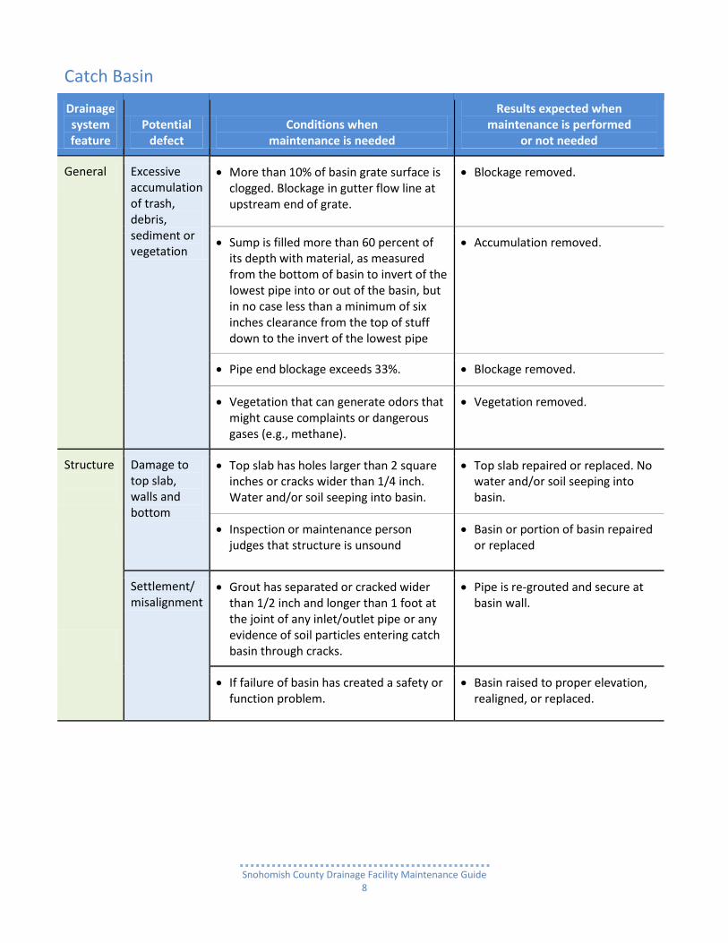
Catch Basin
Drainage system feature
Potential defect
Conditions when maintenance is needed
Results expected when maintenance is performed
or not needed
General
Excessive accumulation of trash, debris, sediment or vegetation
More than 10% of basin grate surface is clogged. Blockage in gutter flow line at upstream end of grate.
Blockage removed.
Sump is filled more than 60 percent of its depth with material, as measured from the bottom of basin to invert of the lowest pipe into or out of the basin, but in no case less than a minimum of six inches clearance from the top of stuff down to the invert of the lowest pipe
Accumulation removed.
Pipe end blockage exceeds 33%. Blockage removed.
Vegetation that can generate odors that might cause complaints or dangerous gases (e.g., methane).
Vegetation removed.
Structure
Damage to top slab, walls and bottom
Top slab has holes larger than 2 square inches or cracks wider than 1/4 inch. Water and/or soil seeping into basin.
Top slab repaired or replaced. No water and/or soil seeping into basin.
Inspection or maintenance person judges that structure is unsound
Basin or portion of basin repaired or replaced
Settlement/ misalignment
Grout has separated or cracked wider than 1/2 inch and longer than 1 foot at the joint of any inlet/outlet pipe or any evidence of soil particles entering catch basin through cracks.
Pipe is re-grouted and secure at basin wall.
If failure of basin has created a safety or function problem.
Basin raised to proper elevation, realigned, or replaced.

Snohomish County Drainage Facility Maintenance Guide
9
Drainage system feature
Potential defect
Conditions when maintenance is needed
Results expected when maintenance is performed
or not needed
Pollutants in storm water or sediment
For typical pollutants present such as gasoline, oil, herbicides, pesticides and fertilizer, identify and remove source and/or report to Snohomish County Surface Water Management (SWM). Illicit Discharge and Detection Elimination (IDDE).
If hazardous materials are present, call 911 and Snohomish County Surface Water Management.
No pollutants present.
Catch Basin opening or concrete slab Access Hole
Solid lid or grate not in place
Solid lid or grate is missing or ajar and not set securely in the metal frame. This is a safety hazard. Lid needs to be secured or replaced immediately.
Missing solid lid or grate repaired or replaced.
Ajar solid lid or grate is fully in place.
Metal Grates and Grate Frames
Locking mechanism not working
Mechanism cannot be opened by a maintenance person with proper tools. Bolts into frame have less than 1/2 inch of thread.
Mechanism can be opened with proper hand tools.
Solid lid or grate difficult to remove
A maintenance person cannot remove lid or grate with normal lifting and proper hand tools.
Solid lid or grate can be removed by a maintenance person.
Grate opening unsafe
Grate with slots or holes wider than standard 7/8 inch is a pedestrian and bike safety hazard. Replace grate.
Substandard Grate is replaced with one having standard openings.
Damaged or missing
Grate with missing or broken member(s) of the grate. This is a safety hazard. Replace immediately.
Grate has been replaced.
Not set and/or properly secured on top slab
Frame not sitting flush on top slab, i.e., separation of more than 3/4 inch of the frame from the top slab.
Frame is sitting flush on the riser rings or top slab.

Snohomish County Drainage Facility Maintenance Guide
10
Drainage system feature
Potential defect
Conditions when maintenance is needed
Results expected when maintenance is performed
or not needed
Metal Grates and Grate Frames
Not set and/or properly secured on top slab
Frame not securely attached to top slab. This is a safety hazard. Replace immediately.
Frame securely attached.
Ladder Unsafe Missing rungs.
Not securely attached to basin wall
Misaligned
Rust
Cracks
Sharp edges. This is a safety hazard. Replace immediately.
Ladder is safe.
Repaired to specifications, or
Replaced with OSHA standards compliant ladder.
CAUTION: A Type 2 Catch Basin is an enclosed space where harmful chemicals and gasses can collect. Therefore, the inspection and maintenance of these facilities should be conducted by individuals trained and certified to work in confined spaces under hazardous conditions.

Snohomish County Drainage Facility Maintenance Guide
11
Yard Drain & Cleanout
What is a Yard Drain? A Yard Drain is similar to a Type 1 Catch Basin but smaller (most are 12 to 18 inches in diameter).
Currently, the most frequently used type of yard drain is a high density polyethylene (HDPE) pipe: o set vertically on end, o with the bell end up fitted with a grate, and o the bottom end resting on washed drain rock.
There are older versions which are made of either polyvinylchloride (PVC) or Concrete Pipe.
How does a Yard Drain work? Yard Drain systems usually consist of several yard drains and 6”-8” diameter HDPE pipe between them. They are designed for use in private residential or commercial property and not for use in public or private streets and roads.
They function as an intermediary stormwater conveyance system that connects roof and building foundation footing drains (4”-6” diameter HDPE pipe) to the main stormwater conveyance system of:
o Type 1 or 2 Catch Basins, and o 12” and larger diameter HDPE pipe.
Typically, in residential subdivisions these systems can be located along lot lines.
Yard Drains also have commercial property applications, often being installed to connect building roof and footing drains To the parking area and driveway drainage systems.
NOTE: If Yard Drains are not visible, it is possible that Cleanouts were installed as a substitute. This is generally the case when the depth from the top of the Yard Drain grate to what would be the top of the washed drain rock exceeds 42”. (See drawings below.)
Common maintenance needs The most common tool for cleaning Yard Drains or Cleanouts is a yard hose. Cleaning by a vactor truck with its very high pressure and volume washing and vacuum system can destroy both the older Yard Drains or Cleanouts and pipe. It is better to use a low pressure washing system and scoop out by hand any mud and debris collecting in the Yard Drains or Cleanouts.

Snohomish County Drainage Facility Maintenance Guide
12
Yard Drain

Snohomish County Drainage Facility Maintenance Guide
13
Cleanout

Snohomish County Drainage Facility Maintenance Guide
14
Yard Drain & Cleanout
Drainage system feature
Potential defect
Conditions when maintenance is needed
Results expected when maintenance is performed
or not needed
Metal Grates
Excessive accumulation of trash, debris, sediment and vegetation
Obstruction Immediately in front of the drain grate or covering it is reducing flow causing ponding or partial flow bypass.
Obstruction removed.
Obstructing more than 1/3 of inlet or outlet pipe diameter.
Obstruction removed.
Decaying and generating odors that could cause complaints or dangerous gases (e.g., methane).
Vegetation removed.
Not in place Missing or only partially in place. Grate in place, repaired or replaced.
Damaged Broken Grate repaired or replaced.
Sump Sediment, accumulation
Sediment exceeds 60 percent of the sump depth.
Measure from bottom of basin to invert of the lowest, but in no case less than a minimum of 6 inches clearance from the sediment surface to the invert of the lowest pipe.
Sediment removed.
Structure
Cracks in wall Cracks in wall Basin repaired or replaced.
Pipe is re-grouted and secure at basin wall.
Settlement or misalignment
Settlement or misalignment Basin raised, realigned, repaired or replaced.
Pollutants in water or sediment
Most commonly occurring are herbicides and insecticides.
Identify and remove source.
Pollutants removed.

Snohomish County Drainage Facility Maintenance Guide
15
Storm Drainage Pipe
What is Drainage Pipe? Storm Drainage Pipes are an alternative to ditches for conveying storm water runoff.
Most drainage pipes are installed underground as part of a drainage network connected by catch basins for sending runoff to an engineered collection facility or to a natural body of water such as a stream.
Culverts, are also drainage pipe, but are generally short runs of pipe open at both ends and usually associated with connecting ditches between driveways and stream crossings under roads.
Other aspects to conveying storm water runoff through Drainage Pipe which has been fabricated with perforations:
discharging runoff directly into the ground through the perforated pipe bedded in a gravel filled trench so that the water will infiltrate through the soil to remove pollutants,
discharging runoff through perforated pipe as sheet flow over the ground surface to a body of water, and
collecting excess surface and ground water in perforated pipe bedded in a gravel filled trench (i.e., French Drain) to direct it away from buildings or soggy ground and to be discharged to an approved site.
Another very important utilization of Drainage Pipe is for the temporary storage of runoff in large diameter pipes (See Detention Pipe).
Cleaning Drainage Pipe Pipes are usually cleaned by a heavy duty power washing and vacuum “vactor” truck (see Catch Basins) to remove flow blockages caused by sediment, trash, debris or vegetation accumulation either in a pipe or a catch basin.
It is important that the Catch Basin is clear of sediment, vegetation or debris that would inhibit a vactor truck equipment from entering the pipe to clean it out (See Catch Basin). Stormwater pipes must be clear of obstructions and not have structural defects (such as warps, cave-ins, penetrating cracks or holes and breaks at pipe joints to prevent water leakage. Both obstructions and structural defects could result in localized soil saturation, erosion, sink holes or flooding.
If the blockage cannot be removed by pressure washing and vacuuming or by hand, then the pipe should be inspected by mobile closed circuit TV to determine the extent and nature of the blockage. This will also help determine whether to continue with standard maintenance procedures, or to repair or replace the pipe will solve the problem.
CAUTION: A Storm Drain Pipe connected to a Catch Basin is considered an enclosed space where harmful chemicals and gasses can collect. Therefore, the inspection and maintenance of such Drain Pipe connected to Catch Basins should be conducted only by individuals trained and certified to work in confined spaces under hazardous conditions.

Snohomish County Drainage Facility Maintenance Guide
16
Clean CMP with some rusting and scaling in normal flow zone
Clean Corrugated Metal Pipe (CMP) with some caked sediment sticking above normal flow zone
Types of Storm Drainage Pipe

Snohomish County Drainage Facility Maintenance Guide
17
Storm Drainage Pipe
Drainage system feature
Potential defect
Conditions when maintenance is needed
Results expected when maintenance is performed
or not needed
Pipe Root obstruction
Root enters or deforms pipe, reducing flow.
Roots removed by mechanical methods only. NOTE: The use of root-dissolving chemicals in storm drainage pipe is prohibited.
Dented or broken
Inlet/outlet Pipe damaged or broken and needs repair.
Pipe repaired and/or replaced.
Rusted or deteriorated
Any part of the Pipe that is crushed or deformed more than 20% or any other failure to the pipe.
Pipe repaired and/or replaced.
Excessive accumulation of trash, debris, sediment and vegetation
Depth is greater than 20% of pipe diameter.
Trash, debris, sediment and vegetation accumulation removed.
Debris Barrier/Trash Rack missing Joint/seal separated, cracked, or broken
Pipe, other than road/driveway cross culverts not connected to Catch Basins, greater than 18 inch diameter need Debris Barriers.
Missing Debris Barriers replaced on 18” diameter or larger Pipe ends other than culverts.
Separation or crack wider than 1/2 inch and longer than 1 foot; or any evidence of soil particles entering pipe through cracks.
Joint/seal is repaired or replaced. If necessary, one or both pipes replaced.

Snohomish County Drainage Facility Maintenance Guide
18
Debris Barrier (Trash Rack)
What is a Debris Barrier? A Debris Barrier (DB) is a metal bar grate over the intake end of a storm drainage conveyance Pipe. The purpose for such a barrier is to prevent man-made and vegetative debris from clogging or plugging a closed pipe system. It also provides a deterrent for keeping animals and people from entering.
DBs have historically been installed on: o the upstream (intake) end of pipe 12” in diameter or greater, and o only occasionally on the downstream (outlet) end.
Snohomish County Code requires trash racks on all opened ended pipe, other than culverts, that are 18” in diameter or greater.
Culverts are generally associated with: o driveway crossings over roadside ditches, and o roads crossings over streams.
Common maintenance needs The primary concern with Debris Barriers is excessive debris and sediment accumulation clogging the rack causing water to backup and flooding damage to downstream roadways, property, and fish and wildlife habitat. Preventing clogging requires on-going and frequent maintenance.
Horizontal Debris Barrier

Snohomish County Drainage Facility Maintenance Guide
19
Aluminum horizontal Debris Barrier
Aluminum horizontal Debris Barrier with bent bar needing repair
Aluminum horizontal Debris Barrier
Aluminum horizontal Debris Barrier with metal flared end side walls and bottom flow pad
Aluminum horizontal Debris Barrier partially clogged with algae
Aluminum horizontal Debris Barrier with bars covered with leaf and twig debris, but water flowing below the barrier
Horizontal Debris Barrier

Snohomish County Drainage Facility Maintenance Guide
20
Vertical Debris Barrier
Conical Debris Barrier

Snohomish County Drainage Facility Maintenance Guide
21
Stormwater Pond Type 2 Catch Basin Overflow Structure with vertical conical galvanized steel Debris Barrier
Stormwater Pond Type 2 Catch Basin Overflow Structure with vertical conical galvanized steel Debris Barrier
Stormwater Pond Overflow Structure with vertical “Top Hat” aluminum Debris Barrier set in “pea” gravel filtration cone
Stormwater Pond with Type 1 Catch Basin with Galvanized steel “Bee Hive” Debris Barrier
Common Vertical Debris Barriers

Snohomish County Drainage Facility Maintenance Guide
22
Debris Barrier (Trash Rack)
Drainage system feature
Potential defect
Conditions when maintenance is needed
Results expected when maintenance is performed
or not needed
Debris Barrier
Trash, Debris, sediment and vegetation accumulation
More than 20% of the barrier obstructed.
Obstruction removed.
Damaged or missing bars.
Bars bent out of shape more than 3 inches.
Bars no more than 3/4 inch out of alignment.
Bars missing or entire barrier missing. Bars in place.
Bars loose and rust causing 50% deterioration to any part of barrier.
Bars repaired or replaced.
Barrier replaced if necessary.
Pipe ends Debris Barrier missing or not attached to pipe. Replace immediately.
Barrier replaced and/or firmly attached to pipe.

Snohomish County Drainage Facility Maintenance Guide
23
Energy Dissipater
What is an Energy Dissipater and how does it work? An Energy Dissipater is usually installed at an outlet (downstream) end of a pipe discharging its flow to either a natural body of water (stream, lake, wetland and Puget Sound) or an engineered ditch or pond (See Stormwater Facility Discharge Point). It is designed to reduce the energy of flowing stormwater in order to prevent erosion at the point of discharge. Often, energy dissipation is also applied to dampen the flow of water at the inlet (upstream) end of a pipe before it enters a pipe.
How does an Energy Dissipater Work? There are several kinds of Energy Dissipaters which include:
rock armoring splash pads,
rock filled metal wire gabion baskets,
dispersion trenches,
excavated stilling pools or basins, and
Type 2 Catch Basins (with or without a lid).
Typical Energy Dissipater design The most common Energy Dissipater is the rock armoring splash pad. It is typically designed:
4 feet to 10 feet long X 2 feet to 6 feet wide and a minimum of 1 foot deep; and
Of 8 inch to12-inch angular rocks;
With the Pipe end resting on top of the rock pad;
The width of the pad extending up the slope to an elevation at least 12” above the top of pipe.
NOTE: Often a sheet of geotextile fabric lines the bottom of the rock pad, sandwiched between the rock layer and the soil sub-grade wrapping around the Pipe.
Common maintenance needs Remove sediment, vegetation debris and man-made trash to prevent flow:
clogging of outlet pipe end – so flow will not back up, or
full or partial burying of an energy dissipater – to reduce loss of flow energy dissipation.

Snohomish County Drainage Facility Maintenance Guide
24
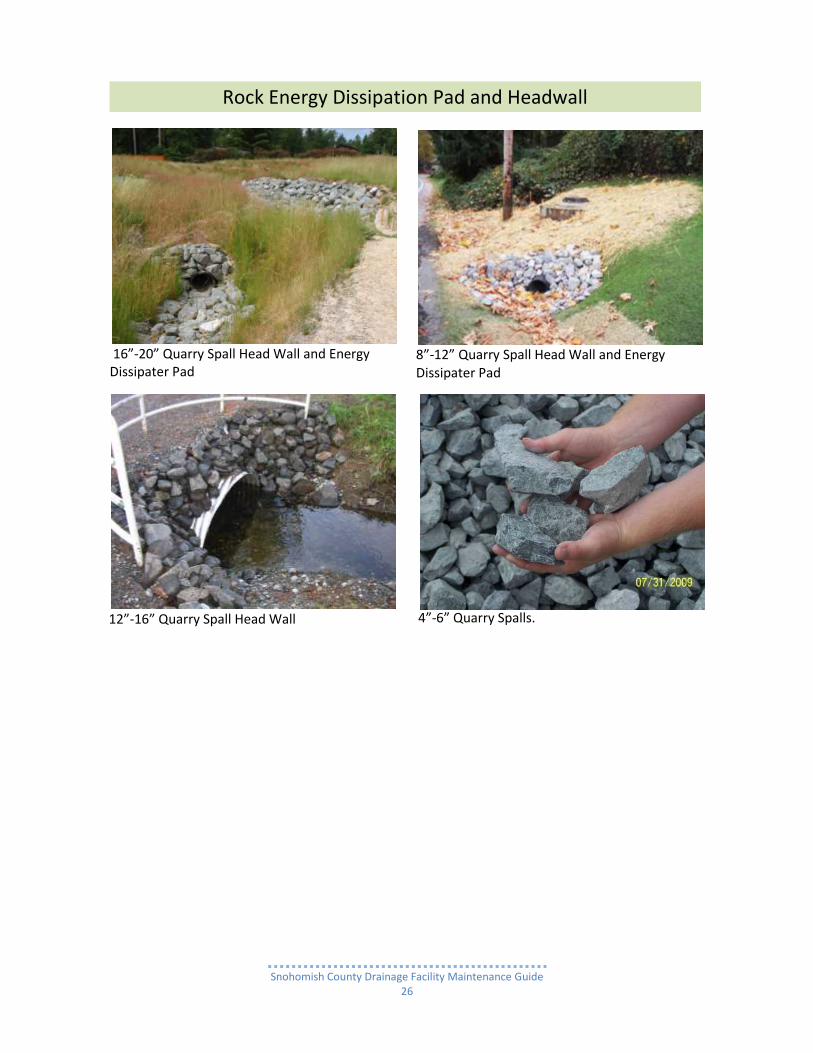
Rock Energy Dissipation Pad and Headwall

Snohomish County Drainage Facility Maintenance Guide
25
Rock Energy Dissipation Pad and Headwall
Snohomish County Drainage Facility Maintenance Guide
26
16”-20” Quarry Spall Head Wall and Energy Dissipater Pad
8”-12” Quarry Spall Head Wall and Energy Dissipater Pad
12”-16” Quarry Spall Head Wall
4”-6” Quarry Spalls.
Rock Energy Dissipation Pad and Headwall

Snohomish County Drainage Facility Maintenance Guide
27
Energy Dispersion Trench

Snohomish County Drainage Facility Maintenance Guide
28
Slope Drain Diffuser Tee
Snohomish County Drainage Facility Maintenance Guide
29
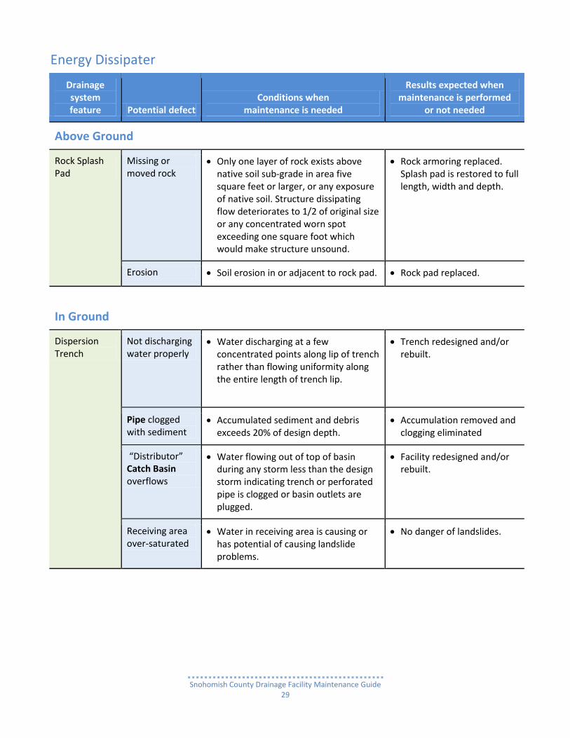
Energy Dissipater
Drainage system feature Potential defect
Conditions when maintenance is needed
Results expected when maintenance is performed
or not needed
Above Ground
Rock Splash Pad
Missing or moved rock
Only one layer of rock exists above native soil sub-grade in area five square feet or larger, or any exposure of native soil. Structure dissipating flow deteriorates to 1/2 of original size or any concentrated worn spot exceeding one square foot which would make structure unsound.
Rock armoring replaced. Splash pad is restored to full length, width and depth.
Erosion Soil erosion in or adjacent to rock pad. Rock pad replaced.
In Ground
Dispersion Trench
Not discharging water properly
Water discharging at a few concentrated points along lip of trench rather than flowing uniformity along the entire length of trench lip.
Trench redesigned and/or rebuilt.
Pipe clogged with sediment
Accumulated sediment and debris exceeds 20% of design depth.
Accumulation removed and clogging eliminated
“Distributor” Catch Basin overflows
Water flowing out of top of basin during any storm less than the design storm indicating trench or perforated pipe is clogged or basin outlets are plugged.
Facility redesigned and/or rebuilt.
Receiving area over-saturated
Water in receiving area is causing or has potential of causing landslide problems.
No danger of landslides.

Snohomish County Drainage Facility Maintenance Guide
30
Drainage system feature Potential defect
Conditions when maintenance is needed
Results expected when maintenance is performed
or not needed
Underground
Type 2 Catch Basin
All potential defects
See Catch Basin
Vault All potential defects
See Detention Vault
Rock Gabion Structures
All or portion of metal wire basket matrix deteriorated or broken. Rocks may be missing.
Deterioration determined to be near to breaking. Broken wire results in holes large enough to allow rocks to fall out of basket. Basket has collapsed.
Basket rewired or replaced.
Rocks replaced as necessary.
Metal wire baskets misaligned
Baskets have shifted and no longer providing full energy dissipation or may be prone to tipping or collapse.
Realign or relocate as necessary.

Snohomish County Drainage Facility Maintenance Guide
31
Stormwater Facility Discharge Point
What is a Stormwater Facility Discharge Point? A Stormwater Facility Discharge Point is the location where stormwater runoff flowing (being sent) from a facility’s outfall merges with either a natural or man-made water body (receiving water).
The Point may be an outfall as distinct as a single Pipe with an Energy Dissipater.
It could be less distinguishable, such as: o A single pipe outlet to an underground infiltration trench, or o Even an Infiltration Pond with no flow outlet except seepage through the bottom of the Pond
down to groundwater.

Snohomish County Drainage Facility Maintenance Guide
32
Facility Discharge Point
Drainage system feature
Potential defect
Conditions when maintenance is needed
Results expected when maintenance is performed
or not needed
Pipe or Ditch/Swale Outfall
Obvious signs of pollutants being discharged to receiving water body
For typical pollutants such as gasoline, oil, herbicides, pesticides and fertilizer: Identify & remove source and/or report to Snohomish County Surface Water Management (SWM)
For Hazardous Material call 911 and Snohomish County SWM
Typical pollutants and/or hazardous material eliminated or reduced. NOTE: If source cannot be eliminated: Discharge Point is being monitored and on-going action is being taken by SWM or the State Department of Ecology.
Soils in and around receiving area are saturated
Water in receiving area is causing soils to become saturated and unstable.
NOTE: Report to Snohomish County SWM Stormwater Facility Maintenance Program for Evaluation.
Receiving area solids are stable.
Off site bank erosion upstream and/or downstream
Erosion in ditch or stream banks due to flow channelization, or higher flows.
NOTE: Report to Snohomish County SWM Stormwater Facility Maintenance Program for Evaluation
Ditch or stream banks stable.
Energy Dissipater
Trash, debris, sediment or vegetation accumulation
More than 10% of energy dissipater pad surface is covered, and/or accumulation depth is greater than 20% of the outlet pipe diameter.
No blockage or clogging of pad surface
Pipe
Obstructions, including roots
Roots or debris enters pipe or deforms pipe, reducing flow.
Roots removed by mechanical methods only. NOTE: The use of root-dissolving chemicals in storm drainage pipe is prohibited.

Snohomish County Drainage Facility Maintenance Guide
33
Drainage system feature
Potential defect
Conditions when maintenance is needed
Results expected when maintenance is performed
or not needed
Pipe Pipe deterioration due to physical stress or chemical reaction
Any part of the Pipe that is broken crushed or deformed more than 20% or
Deterioration has reduced Pipe material thickness, caused cracking or clogging inside Pipe.
Pipe repaired or replaced.

Snohomish County Drainage Facility Maintenance Guide
34
Flow Control Structure
What is a Flow Control Structure? Flow Control Structures (FCS) are the most critical component of the many types of stormwater facilities that collect and remove pollutants (see list below). Their function is to:
regulate the volume of stormwater runoff flowing out of a facility to prevent flooding and/or destruction of stream habitat, or
split off a portion of flow in a conveyance system (pipe or ditch) so that amount will bypass an area to avoid flooding it and/or avoid disrupting the effectiveness of a downstream detention or pollutant reduction treatment facility.
It is crucial that the flow of stormwater is released at the engineered design rate at all times.
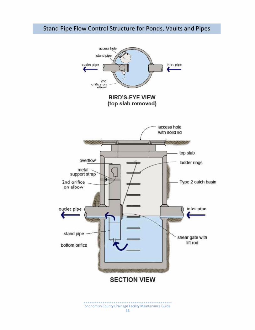
Typical Flow Control Structure Design In Snohomish County the most commonly utilized the Standpipe Flow Control Structure. The structure is a Type 2 Catch Basin (CB) housing a vertical metal standpipe apparatus strapped to the interior face of the CB wall called a Standpipe Flow Control Structure (See photos and details below). There is also a Weir Flow Control Structure which is relatively common, but mostly used with detention ponds built in the 1980s and 90s.
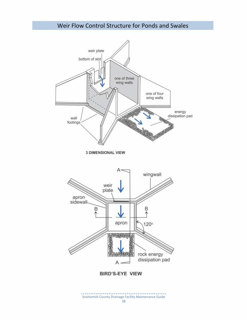
It is a concrete wall set in a pond’s perimeter berm (functions as a dam) with a notch precisely formed at the top to release stormwater runoff at a specific rate.
The shape of a “notch” is either, rectangular with one or more steps narrowing from top to bottom or a “V”. The shape affects the flow rates. The choice of shape is a site specific engineering consideration for how best to control the rate of flow leaving a stormwater facility. See photos and details below.
Location of Flow Control Structures Location is critical for efficient flow regulation and passage downstream as well as for maintenance accessibility. For a facility like a pond, they are generally located at the “downstream end” of a pond, which is the point where flow from the pond will most effectively merge with the natural or man-made body of water downstream of the outfall. The control structure can be located at that point in one of three places: on top of the berm damming the water or on either the interior (inside the water impoundment area) or exterior side slope of the berm.
A concrete weir structure can only be located at the top of the berm.
In the case of an underground detention vault or pipe, the flow control structure is located at the “downstream end” and is outside of the vault or pipe.
Some vaults, especially those installed in the 1980s and 90s have the Flow Control Standpipe located inside the Vault. For the underground large sized Detention Pipe, the structure is separated from the Pipe at the “downstream” end by a Pipe of smaller diameter (usually 36”) than the Detention Pipe.
Common maintenance needs Lack of maintenance is the chief factor contributing to flow disruption, often resulting in downstream flooding which can cause property damage and destruction of fish and wildlife habitat. Flooding is usually the result of stormwater runoff backing up and overflowing a facility. This backup is typically due to a plugged or broken flow control device, thereby allowing the flow out of a facility to greatly exceed the design flow rate.

Snohomish County Drainage Facility Maintenance Guide
35
The usual culprits for plugging are floating debris and trash such as vegetation, plastic bags or soccer balls which can cover or partially block the flow. Sediment may also build up in the bottom of the Control Structure whereby the flow control device becomes fully or partially buried. If a Flow Control Structure appears to be malfunctioning, Snohomish County Surface Water Management (SWM) should be notified as soon as possible so that the structure can be inspected promptly. If any immediate maintenance, repair or replacement is necessary, the County requires that the owner of the facility complete the necessary work within 30 days of receiving notification from SWM documenting the nature of the problem and what work needs to be done.
Facilities typically associated with a control structure/flow restrictor include: Detention Pond
Detention Vault
Detention Pipe(Tank)
Proprietary Media Filter Vault
Conveyance Pipe (bypass)
Biofiltration Swale
Constructed Wetland
Wet Pond
Wet Pond w/detention
Wet Vault
Wet Vault w/detention
Snohomish County Drainage Facility Maintenance Guide
36
Stand Pipe Flow Control Structure for Ponds, Vaults and Pipes

Snohomish County Drainage Facility Maintenance Guide
37
Typical location of a Type 2 Catch Basin with Stand Pipe Flow Control Structure for a Stormwater Pond
View from open round access hole showing the standpipe with orifice elbow and shear gate with its “lift rod” detached.
View from rectangular access hole showing the access ladder and standpipe with orifice elbow and shear gate with attached “lift rod”
Type 2 Catch Basin Stand Pipe Flow Control Structure interior with debris (mostly tree limbs and fir needles)
Type 2 Catch Basin Stand Pipe Flow Control Structure interior with debris (mostly paper and plastic cups and containers
Note: Hole in Disk at bottom of Standpipe is flow regulating orifice
Type 2 Catch Basin Flow Control Structure
Snohomish County Drainage Facility Maintenance Guide
38
Weir Flow Control Structure for Ponds and Swales

Snohomish County Drainage Facility Maintenance Guide
39
Weir Flow Control Structure for Ponds and Swales

Snohomish County Drainage Facility Maintenance Guide
40
Weir is metal plate with deep rectangular notch
Weir is metal plate with a combination of a lower “V” notch and upper wide rectangular notch
Weir is a “V” notch in a concrete wall
Weir Flow Control Structure

Snohomish County Drainage Facility Maintenance Guide
41
Type 2 Catch Basin Pond Overflow Structure

Snohomish County Drainage Facility Maintenance Guide
42
Flow Control Structure
Drainage system feature
Potential defect
Conditions when maintenance is needed
Results expected when maintenance is performed
or not needed
Stand-pipe Structural damage
Structure is not securely attached to Catch Basin or Vault wall.
Structure securely attached to wall and outlet Pipe.
Structure is not in upright position (allow up to 10% from plumb).
Structure in correct position.
Connections to outlet Pipe are not watertight and show signs of rust.
Connections to outlet pipe are water tight.
Structure repaired or replaced and works as designed.
Any holes, other than designed holes, in the structure.
Structure has no holes other than designed holes.
Any material blocking or having the potential of blocking the Pipe overflow.
Top of pipe overflow is free of all obstructions and works as designed.
Cleanout Gate
Damaged or missing
Cleanout gate is not watertight or is missing.
Gate is watertight and works as designed.
Gate cannot be moved up and down by one maintenance person.
Gate moves up and down easily and is watertight.
Chain/rod leading to gate is missing or damaged.
Chain is in place and works as designed.
Gate is rusted over 50% of its surface area.
Gate is repaired or replaced to meet design standards.
Standpipe Orifice Plate & Orifice Elbows.
Damaged or missing
Control device is not working properly due to missing, out of place, or bent orifice plate.
Plate is in place and works as designed.
Weir Plate Obstructions Any trash, debris, sediment, or vegetation blocking the plate.
Plate is free of all obstructions and works as designed.
Type 2 Catch Basin
All potential defects
See Catch Basin.
Snohomish County Drainage Facility Maintenance Guide
43
Drainage system feature
Potential defect
Conditions when maintenance is needed
Results expected when maintenance is performed
or not needed
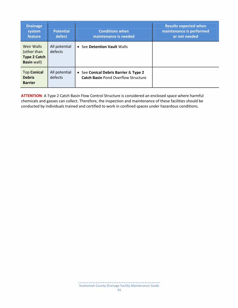
Weir Walls (other than Type 2 Catch Basin wall)
All potential defects
See Detention Vault Walls
Top Conical Debris Barrier
All potential defects
See Conical Debris Barrier & Type 2 Catch Basin Pond Overflow Structure
ATTENTION: A Type 2 Catch Basin Flow Control Structure is considered an enclosed space where harmful chemicals and gasses can collect. Therefore, the inspection and maintenance of these facilities should be conducted by individuals trained and certified to work in confined spaces under hazardous conditions.

Snohomish County Drainage Facility Maintenance Guide
44
Detention Pond
What is a Detention Pond? A stormwater Detention Pond is a constructed open earthen basin which temporarily stores stormwater runoff originating from impervious surfaces such as streets, sidewalks, driveways, parking lots and roofs. The runoff is conveyed to a Detention Pond either by a pipe system, ranging in diameter from 8” to 30”, or combined drainage ditch and pipe system. The pond is either fully dug out of the ground, or partially dug out with the remainder of the basin’s perimeter formed by a compacted earthen berm (embankment) which functions as a dam. There are some Detention Ponds with walls completely or partially constructed of poured-in- place concrete, concrete blocks or large quarry rock. Detention Ponds are usually located at the lowest spot possible on a site and as close as possible to either a natural water body (stream, wetland, lake or Puget Sound) or an engineered drainage system.
How does a Detention Pond work? A Detention Pond temporarily stores runoff and slowly discharges the runoff through a Flow Control Structure outlet. The flow out of a pond is regulated (restricted) to prevent damage to downstream property damage and fish/wildlife habitat. Detention Ponds are designed to completely drain whatever amount of runoff is stored up over several days after a storm event has lessened considerably or ceased.
Typical Detention Pond designs The “Flow Through” is the simplest design and most utilized throughout Snohomish County. Stormwater runoff flows in one end of the pond and flows out the other through the Flow Control Structure. (See “Flow Through” Pond drawing) The other type is a “Backup” Pond. Backup Ponds were common from the 1970s through the 1980s. It is still utilized when site conditions warrant it, but only as an alternative to the “flow through” pond. This is designed for runoff to both enter and exit the pond through the Flow Control Structure.
Stormwater will bypass the pond until the volume is great enough, due to the increased intensity of a storm that the flow can no longer just go out the outlet pipe from the Flow Control Structure.
It is forced to also enter (be backed up) into the pipe from the Flow Control Structure to the pond to be stored (detained) until the storm subsides.
As the storm subsides and the flow volume decreases, the runoff stored in the pond is released back to the Flow Control Structure and the outlet pipe. (See drawing below – “Backup Detention Pond)
Ponds can vary greatly in size, shape, depth, as well as appearance which can range from little or no vegetation to well manicured or the natural look garnished with native vegetation.
Generally, a more natural-appearing pond with native vegetation is preferred for reduced maintenance purposes and enhanced wildlife habitat.
Some facilities are even designed to appear as natural water bodies or are set in park-like settings.
Common maintenance needs Over time, ponds accumulate a sufficient amount of sediment, trash, as well as man-made and vegetative debris that reduces a pond’s storage capacity. When storage capacity becomes unacceptably compromised, the accumulation will need to be removed.
Remove trash and vegetation debris
Prevent pond and pipe system clogging
Sediment removal

Snohomish County Drainage Facility Maintenance Guide
45
Detention Ponds

Snohomish County Drainage Facility Maintenance Guide
46
Pond with wall made of Gabion Basket (wire mesh rectangular baskets filled with rock chunks)
Pond berm with Type 2 Catch Basin Flow Control Structure at top of berm
Detention Ponds

Snohomish County Drainage Facility Maintenance Guide
47
Detention Pond
Drainage system feature
Potential defect
Conditions when maintenance is needed
Results expected when maintenance is performed
or not needed
General Site Conditions Surrounding Pond General Site Conditions
Trash and debris accumulation
Site generally littered with trash & debris.
Trash and debris removed.
Evidence of dumping. Neighbors notified that dumping is prohibited.
“No dumping” signs installed.
Poisonous vegetation and noxious weeds
Poisonous or nuisance vegetation constituting a hazard to maintenance personnel or the public. NOTE: Evidence of noxious weeds as defined by the Snohomish County Noxious Weed Control Board requires eradication based on the Board’s recommendation of Herbicide application or mechanical means.
Poisonous vegetation eradicated on site. NOTE: Complete eradication of noxious weeds may not be possible. Compliance with State and County Noxious Weed Control Boards is required.
Contaminants and pollutants
Any evidence of oil, gasoline, contaminants or other pollutants in or near the pond area. For hazardous material, call 911 and Snohomish County SWM.
No contaminants or pollutants present.
Beaver dams Dammed up Flow Control Structure either in pond or downstream of facility results in change of facility function. NOTE: Coordinate trapping of beavers and removal of dams with appropriate state and county permitting agencies.
Facility is fully functional.
Rodent holes Evidence of rodent holes on site, but not in pond area.
Rodents eliminated.

Snohomish County Drainage Facility Maintenance Guide
48
Drainage system feature
Potential defect
Conditions when maintenance is needed
Results expected when maintenance is performed
or not needed
Surrounding Pond
Insects Insects such as wasps and hornets interfere with maintenance activities. NOTE: Apply insecticides in compliance with manufacturer’s directions.
Insects eliminated.
Tree growth and hazard trees
Specific trees hinder maintenance access or interfere with maintenance activity (i.e., slope mowing, silt removal, vactoring or equipment movements).
Only Trees hindering maintenance activity removed.
Hazard trees (dead, diseased, or dying) are identified. NOTE: A certified arborist should be consulted to determine health of tree or removal requirements.
Hazard trees removed.
NOTE: Harvested trees should be recycled into mulch or other beneficial uses (e.g., alders for firewood).
Erosion Eroded damage over 2 inches deep where cause of damage is still present or where there is potential for continued erosion.
Slopes stabilized using appropriate erosion control measures; e.g., rock reinforcement, planting of grass, compaction.
Pond Side Slopes (natural or excavated)
Tree growth Trees growing below pond Emergency Overflow elevation subject to blowing over, uprooting the root wad due to water saturated soil. An exposed wad and hole in left in the soil can be a major source of continued erosion.
Trees removed.
Roots removed as necessary.
Erosion Eroded damage over 2 inches deep where cause of damage is still present or where there is potential for continued erosion.
Slopes stabilized using appropriate erosion control measures; e.g., rock reinforcement, planting of grass, compaction.
Snohomish County Drainage Facility Maintenance Guide
49
Drainage system feature
Potential defect
Conditions when maintenance is needed
Results expected when maintenance is performed
or not needed
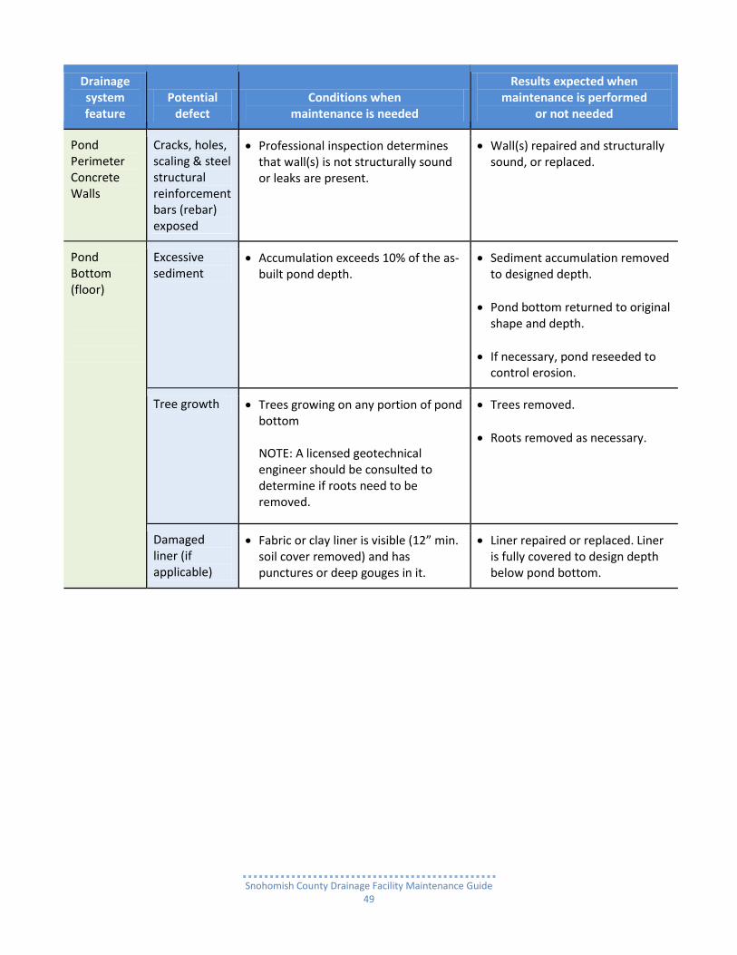
Pond Perimeter Concrete Walls
Cracks, holes, scaling & steel structural reinforcement bars (rebar) exposed
Professional inspection determines that wall(s) is not structurally sound or leaks are present.
Wall(s) repaired and structurally sound, or replaced.
Pond Bottom (floor)
Excessive sediment
Accumulation exceeds 10% of the as-built pond depth.
Sediment accumulation removed to designed depth.
Pond bottom returned to original shape and depth.
If necessary, pond reseeded to control erosion.
Tree growth Trees growing on any portion of pond bottom NOTE: A licensed geotechnical engineer should be consulted to determine if roots need to be removed.
Trees removed.
Roots removed as necessary.
Damaged liner (if applicable)
Fabric or clay liner is visible (12” min. soil cover removed) and has punctures or deep gouges in it.
Liner repaired or replaced. Liner is fully covered to design depth below pond bottom.

Snohomish County Drainage Facility Maintenance Guide
50
Drainage system feature
Potential defect
Conditions when maintenance is needed
Results expected when maintenance is performed
or not needed
Pond Perimeter Structural Berms (Dams) Pond Perimeter Structural Berms (Dams)
Soil Settlement
A portion of structural berm (compacted earthen embankment) has settled 4 inches lower than the as-built elevation.
If settlement is apparent, measure berm to determine amount of settlement.
Settling can be an indication of more severe problems with the berm or outlet works. NOTE: A licensed civil engineer should be consulted to determine the source of the settlement.
Berm is repaired and returned to as-built elevation.
Tree Growth Trees growing on any portion of pond interior and exterior slopes as well as the top
Trees removed
Roots removed as necessary.
Slopes stabilized.
Piping Discernable water flow through a compacted structural berm due to tree roots and/or rodent holes/tunnels, can lead to erosion within a berm and structural failure. NOTE: A Geotechnical engineer should be consulted to inspect, evaluate, and recommend a repair solution plan. NOTE: If pond volume exceeds 10 acre-feet, coordinate with the Road Maintenance division of Snohomish County Public Works Department; and State Department of Ecology, Dam Safety Office.
Piping and erosion eliminated.

Snohomish County Drainage Facility Maintenance Guide
51
Drainage system feature
Potential defect
Conditions when maintenance is needed
Results expected when maintenance is performed
or not needed
Pond Clay or Geotextile Liner
Exposed or damaged
Portion of liner is visible. Liner is covered with minimum 12” compacted soil.
Geotextile liner is punctured. Puncture(s) repaired or liner replaced as necessary.
Clay liner has deep gouge(s). Gouge(s) repaired or liner replaced as necessary.
Emergency Overflow Spillway
Rock armoring missing
Rock layer on sub-grade is less than 1.0’ deep and sub-grade is exposed.
Rock depth restored to design depth of 1.0’.
Erosion
Eroded damage over 2 inches deep where cause of damage is still present or where there is potential for continued erosion. NOTE: licensed civil engineer should be consulted to inspect, evaluate, and recommend a repair plan.
Spillway stabilized using appropriate erosion control measure(s); e.g., rock reinforcement or compaction.
Type 2 Catch Basin Emergency Overflow Structure
All potential defects
See Type 2 Catch Basin Pond Overflow Structure.

Snohomish County Drainage Facility Maintenance Guide
52
Detention Vault
What is a Detention Vault? A Stormwater Detention Vault is a large underground reinforced concrete rectangular tank, which temporarily stores stormwater runoff originating from impervious surfaces such as streets, driveways, sidewalks, parking lots and roofs, through pipes or drainage ditches. The runoff is conveyed to the Detention Vault either by a pipe system ranging in diameter from 8” to 30” or a combined drainage ditch and pipe system. Detention Vaults are usually located at the lowest spot possible on a site and as close as possible to either a natural water body (stream, wetland, lake or Puget Sound) or an engineered drainage system.
How does a Detention Vault work? A Detention Vault temporarily stores runoff during storm events and slowly releases the runoff through a Flow Control Structure outlet. The flow out of a vault is regulated (restricted) to prevent damage to downstream property and fish/wildlife habitat. A Detention Vault is designed to completely drain whatever amount of water is stored within several days after a storm event has lessened considerably or ceased.
Typical Detention Vault designs The “Flow Through” is the simplest design and most utilized throughout Snohomish County. Stormwater runoff flows in one end of the vault and flows out the other through the Flow Control Structure. (See drawing labeled “Flow Through” Detention Vault) The other type is a “Backup” Vault. It is an alternative to the ‘Flow Through,” utilized only when conditions warrant it. This is designed for runoff to both enter and exit a vault through the Flow Control Structure.
Stormwater will bypass the vault until the volume is great enough, due to the increased intensity of a storm that the flow can no longer just go out the outlet pipe from the Flow Control Structure.
It is forced to also enter (be backed up) into the pipe from the Flow Control Structure to the vault to be stored (detained) until the storm subsides.
As the storm subsides and the flow volume decreases, the runoff stored in the vault is released back to the Flow Control Structure and the outlet pipe. (See drawing labeled “Backup Detention Vault.)
A Detention Vault is typically utilized at a site that does not have space available for a ground level Detention Pond system.
In commercial projects they are usually installed beneath parking lots and driveways.
In residential projects (plats) they are located primarily in separate tracts of land dedicated for drainage purposes where a play area/sport court can be installed on top of vault’s concrete lid, and occasionally in drainage easements across sides and backs of lots or under private streets.
Common maintenance needs Over time a vault accumulates a sufficient amount of sediment along with vegetation debris and trash, which reduces its storage capacity. When storage capacity becomes unacceptably compromised, the accumulation will need to be removed.
Remove trash and vegetation debris
Prevent pond and pipe system clogging
Sediment removal

Snohomish County Drainage Facility Maintenance Guide
53
Detention Vault

Snohomish County Drainage Facility Maintenance Guide
54
Detention Vault
Drainage system feature
Potential defect
Conditions when maintenance is needed
Results expected when maintenance is performed
or not needed
Vault Chamber(s)
Floating debris accumulation
Any debris accumulated in vault, pipe or inlet/outlet.
All floating debris removed.
Sediment and non-floating debris accumulation
Accumulation on bottom exceeds 6-inches.
All sediment and debris removed from bottom.
Plugged or damaged pipes
Inlet/outlet pipe(s) plugged, damaged or broken and needs repair.
Pipe unplugged, repaired and/or replaced.
Vault Concrete Lid
Access hole cover damaged/not working or missing
Cover cannot be opened or removed by an individual.
Missing cover is safety hazard.
Cover repaired or replaced.
Vault Bottom, Walls & Lid
Cracks, holes, scaling & steel structural reinforcement bars (rebar) exposed
Professional inspection determines that vault is not structurally sound or leaks are present.
Vault repaired and structurally sound, or replaced.
Cracks wider than ½-inch at the joint of any inlet/outlet pipe or evidence of soil particles entering through the cracks.
Cracks repaired and no cracks exist wider than ¼-inch.
Baffles Signs of structural failure
Baffles corroding, cracking, warping and/or showing signs of failure as determined by maintenance/inspection staff.
Baffles repaired or replaced to specifications.
Snohomish County Drainage Facility Maintenance Guide
55
Drainage system feature
Potential defect
Conditions when maintenance is needed
Results expected when maintenance is performed
or not needed
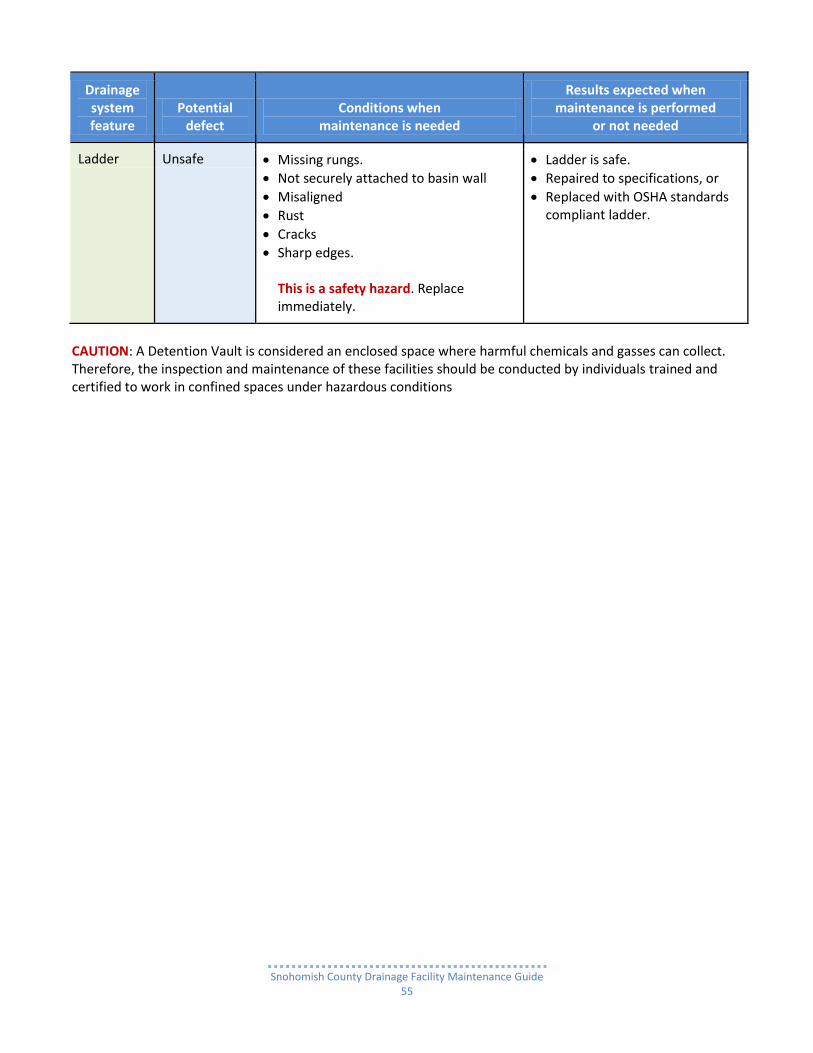
Ladder Unsafe Missing rungs.
Not securely attached to basin wall
Misaligned
Rust
Cracks
Sharp edges. This is a safety hazard. Replace immediately.
Ladder is safe.
Repaired to specifications, or
Replaced with OSHA standards compliant ladder.
CAUTION: A Detention Vault is considered an enclosed space where harmful chemicals and gasses can collect. Therefore, the inspection and maintenance of these facilities should be conducted by individuals trained and certified to work in confined spaces under hazardous conditions

Snohomish County Drainage Facility Maintenance Guide
56
Detention Pipe
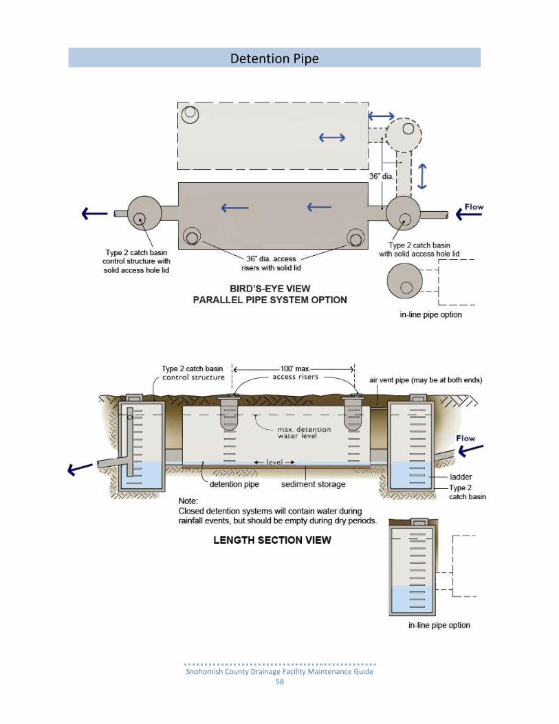
What is a Detention Pipe? Detention Pipes are large underground aluminum or steel corrugated pipe, typically 48” to 120” in diameter, which temporarily store stormwater runoff originating from impervious surfaces such as streets, sidewalks, driveways, parking lots and roofs. The runoff is conveyed to the Detention Pipes either by a pipe system ranging in diameter from 8” to 30” or a combined drainage ditch and pipe system. Detention Pipes are usually located at the lowest spot possible on a site and as close to a natural water body or an engineered stormwater system as possible to discharge to.
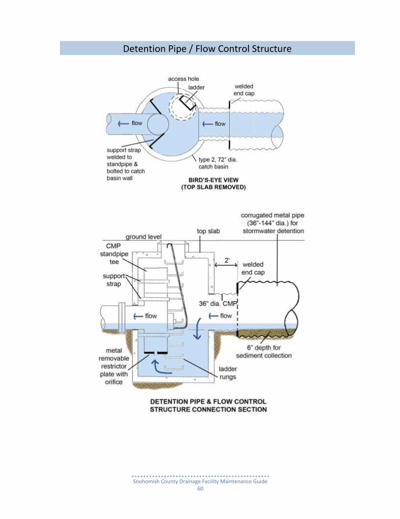
How does a Detention Pipe system work? A Detention Pipe system temporarily stores runoff during storm events, and slowly releases the runoff through a Flow Control Structure outlet to either a natural water body (stream, wetland, lake or Puget Sound) or an engineered conveyance system. The outlet flow is regulated (restricted) to prevent damage to either downstream property or fish and wildlife habitat associated with those water bodies. A Detention Pipe system is designed to completely drain whatever amount of runoff is stored within several days after a storm event has lessened considerable or ceased.
Typical Detention Pipe system designs The “Flow Through” is the simplest design and most utilized throughout Snohomish County. Stormwater runoff flows in one end of the Pipe and flows out the other through the Flow Control Structure. (See drawing labeled “Flow Through” Detention Pipe system) The other type is a “Backup” system. In this design, the runoff both enters and exits the pipe through the Flow Control Structure. It is an alternative to the “flow through” vault when site conditions warrant it. This is designed for runoff to both enter and exit a Detention Pipe system through a Flow Control Structure.
Stormwater will bypass the Detention Pipe until the volume is great enough, due to the increased intensity of a storm that the flow can no longer just go out the outlet pipe from the Flow Control Structure.
It is forced to also enter (be backed up) into the pipe from the Flow Control Structure to the vault to be stored (detained) until the storm subsides.
As the storm subsides and the flow volume decreases, the runoff stored in the vault is released back to the Flow Control Structure and the outlet pipe. (See drawing below – “Backup Detention Pipe).
These Detention Pipe systems are typically utilized at sites that do not have space available for a ground level pond system.
In commercial projects they are usually installed beneath parking lots and driveways.
In residential projects they are located, within drainage easements across sides and backs of lots, under private streets or in tracts of land where a play area/sport court can be installed above the pipe.
Typically these pipes are arranged in one of three configurations:
as a single pipe under 150’ in length, or
with two or more in a line strung together like link sausages with Type 2 Catch Basins connecting them, or
with two or more pipes parallel in 2 or more rows with a connecting manifold at one end and Type 2 Catch Basins at the other end of each row.

Snohomish County Drainage Facility Maintenance Guide
57
Common maintenance needs Over time, Detention Pipe systems accumulate a sufficient amount of sediment, trash, and manmade vegetative debris that reduces their storage capacity. When storage capacity becomes unacceptably compromised, the accumulation will need to be removed.
Remove trash and vegetation debris
Prevent pond and pipe system clogging
Sediment removal
Snohomish County Drainage Facility Maintenance Guide
58
Detention Pipe

Snohomish County Drainage Facility Maintenance Guide
59
Detention Pipe
Snohomish County Drainage Facility Maintenance Guide
60
Detention Pipe / Flow Control Structure

Snohomish County Drainage Facility Maintenance Guide
61
Detention Pipe

Snohomish County Drainage Facility Maintenance Guide
62
Detention Pipe
Snohomish County Drainage Facility Maintenance Guide
63
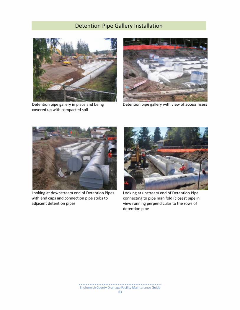
Detention pipe gallery in place and being covered up with compacted soil
Detention pipe gallery with view of access risers
Looking at downstream end of Detention Pipes with end caps and connection pipe stubs to adjacent detention pipes
Looking at upstream end of Detention Pipe connecting to pipe manifold (closest pipe in view running perpendicular to the rows of detention pipe
Detention Pipe Gallery Installation

Snohomish County Drainage Facility Maintenance Guide
64
Detention Pipe
Drainage system feature
Potential defect
Conditions when maintenance is needed
Results expected when maintenance is performed
or not needed
Stormwater Water Storage Area
Air vent pipe plugged
Over one-half of cross section is blocked at any point in length of vent pipe or is damaged.
Vent open and functioning.
Debris and sediment accumulation
Accumulated sediment depth exceeds 10% of pipe diameter.
All sediment, debris, and organic material removed from storage area.
Pipe Structural Problems
Any openings or voids at section joints allowing material to seep into or water to leak out. NOTE: This will require engineering analysis to determine structural stability.
All pipe sections sealed.
Any part bent out of shape more than 10% of its design shape. (Review required by engineer to determine structural stability).
Pipe section repaired or replaced to design.
Any visible holes or any cracks wider than ¼” or
Material seeping in or
Water leaking out or
Maintenance/inspection personnel determine that pipe is not structurally sound.
Pipe repaired or replaced to design specifications and is structurally sound
Pipe Riser Access Hole
Solid metal lid cover
Solid lid is missing or ajar and not set securely in metal frame. This is a safety hazard. Lid needs to be secured or replaced immediately.
Missing solid lid repaired or replaced.
Solid lid or is set securely in metal frame.
Locking mechanism cannot be opened by a maintenance person with proper tools. Bolts into frame have less than 1/2 inch of thread.
Mechanism opens with proper hand tools.

Snohomish County Drainage Facility Maintenance Guide
65
Drainage system feature
Potential defect
Conditions when maintenance is needed
Results expected when maintenance is performed
or not needed
Pipe Riser Access Hole
Solid metal lid cover
A maintenance person cannot remove lid with normal lifting and proper hand tools.
Solid lid can be removed by a maintenance person.
Solid lid missing or broken. This is a safety hazard. Replace immediately.
Solid lid replaced.
Metal frame for solid metal lid
Frame not secured or sitting flush on top of concrete slab.
Frame is secure on top slab.
There is more than 3/4 inch separation of frame from the top slab.
Frame sitting flush on the riser rings or top slab.
Frame not securely attached to top slab. This is a safety hazard. Replace immediately.
Frame securely attached to top slab.
Locking mechanism not working
Locking Mechanism cannot be opened or lock bolts removed by one maintenance person with proper tools.
Mechanism or bolts open with proper tools.
Cover difficult to remove
One maintenance person cannot remove lid after applying normal lifting pressure. .
Cover can be removed and reinstalled by one maintenance person.
Ladder Unsafe Missing rungs.
Not securely attached to basin wall
Misaligned
Rust
Cracks
Sharp edges. This is a safety hazard. Replace immediately.
Ladder is safe.
Repaired to specifications, or
Replaced with OSHA standards compliant ladder.
Type 2 Catch Basin Flow Control Structure
All potential defects
See Type 2 Catch Basin Flow Control Structure w/ Standpipe
CAUTION: A Detention Pipe system is considered an enclosed space where harmful chemicals and gasses can collect. Therefore, the inspection and maintenance of these facilities should be conducted by individuals trained and certified to work in confined spaces under hazardous conditions.

Snohomish County Drainage Facility Maintenance Guide
66
Wet Pond
What is a Wet Pond? A Wet Pond (also known as a Retention Pond) is typically a constructed earthen basin that retains a permanent pool of water throughout the year (or at least through the wet season) to remove pollutants from stormwater runoff.
The runoff is conveyed to a Wet Pond either by a pipe system, ranging in diameter from 8” to 30”, or combined drainage ditch and pipe system.
The pond is either fully dug out of the ground, or partially dug out with the remainder of the basin’s perimeter formed by a compacted earthen berm (embankment) which functions as a dam.
o The sides are usually sloped. However, in order to reduce the size of a pond’s “footprint” the sides are cut vertical and lined with either large quarry rock boulders or concrete blocks forming a wall.
o There are Wet Ponds with the entire perimeter or a portion of it with walls constructed of poured-in- place concrete.
Wet Ponds are usually located at the lowest spot possible on a site and as close as possible to either a natural water body (stream, wetland, lake or Puget Sound) or an engineered drainage system.
How does a Wet Pond work? Pollutants, such as trace metals, nutrients, sediments and organics, are suspended or dissolved in the runoff flowing into a Wet Pond.
They are removed as storm runoff mixes with the water in the pond’s permanent pool.
The greater the length of the time period between storm events (quiescent time), the greater the amount of pollutants removed.
There are several pollutant removal processes.
The primary pollutant removal mechanism is the settling out of suspended (floating) pollutant particles in stormwater runoff that are then deposited as sediment on the permanent pool bottom.
A less significant portion of pollutants are removed when runoff enters the pond en masse (as a flood) and displaces the existing water retained in the pond’s permanent pool.
There are also natural occurring chemical processes that occur in the stormwater runoff soup, which detach dissolved contaminants from the water by:
o Attraction to suspended sediment particles and to sediment building up on the pond bottom, o Coagulation (clotting), a process which causes pollutant particles to combine and form flakes
that eventually settle to the pond bottom, and o Bacterial decomposition.
Some nutrients, such as nitrogen, phosphorus and potassium, typically found in fertilizers, are easily dissolved in stormwater runoff. They are susceptible to removal in Wet Ponds. This capability helps reduce the impact of elevated concentrations (nutrient loading).
o Nutrient loading can trigger the abnormal increase in the supply of organic matter (eutrification), which results in the depletion of oxygen available to aquatic organisms.
o Lack of oxygen in rivers, streams, wetlands and lakes diminishes fish food sources and eliminates their aquatic vegetative habitat.
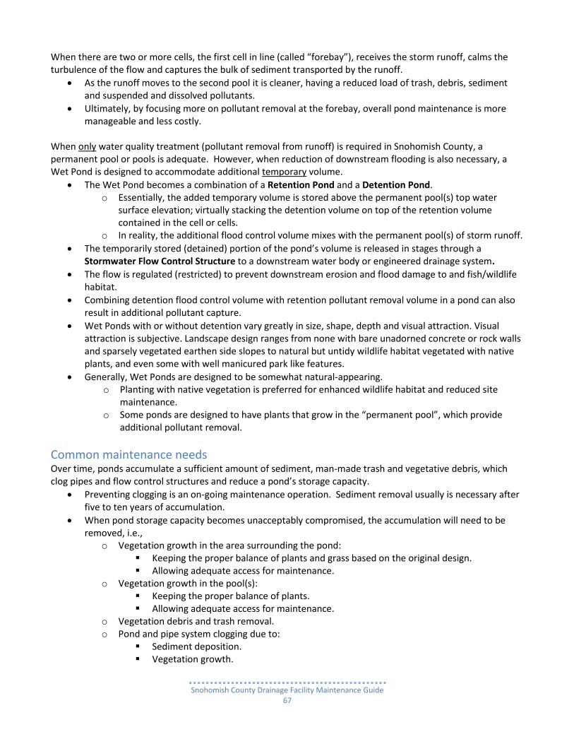
Typical Wet Pond Design Wet Ponds in Snohomish County function as a Retention Pond and are designed either with a single cell or with two or more cells. Each cell holding a permanent pool of water is a retention cell. The source of the water can be precipitation, ground water or storm runoff.
Snohomish County Drainage Facility Maintenance Guide
67
When there are two or more cells, the first cell in line (called “forebay”), receives the storm runoff, calms the turbulence of the flow and captures the bulk of sediment transported by the runoff.
As the runoff moves to the second pool it is cleaner, having a reduced load of trash, debris, sediment and suspended and dissolved pollutants.
Ultimately, by focusing more on pollutant removal at the forebay, overall pond maintenance is more manageable and less costly.
When only water quality treatment (pollutant removal from runoff) is required in Snohomish County, a permanent pool or pools is adequate. However, when reduction of downstream flooding is also necessary, a Wet Pond is designed to accommodate additional temporary volume.
The Wet Pond becomes a combination of a Retention Pond and a Detention Pond. o Essentially, the added temporary volume is stored above the permanent pool(s) top water
surface elevation; virtually stacking the detention volume on top of the retention volume contained in the cell or cells.
o In reality, the additional flood control volume mixes with the permanent pool(s) of storm runoff.
The temporarily stored (detained) portion of the pond’s volume is released in stages through a Stormwater Flow Control Structure to a downstream water body or engineered drainage system.
The flow is regulated (restricted) to prevent downstream erosion and flood damage to and fish/wildlife habitat.
Combining detention flood control volume with retention pollutant removal volume in a pond can also result in additional pollutant capture.
Wet Ponds with or without detention vary greatly in size, shape, depth and visual attraction. Visual attraction is subjective. Landscape design ranges from none with bare unadorned concrete or rock walls and sparsely vegetated earthen side slopes to natural but untidy wildlife habitat vegetated with native plants, and even some with well manicured park like features.
Generally, Wet Ponds are designed to be somewhat natural-appearing. o Planting with native vegetation is preferred for enhanced wildlife habitat and reduced site
maintenance. o Some ponds are designed to have plants that grow in the “permanent pool”, which provide
additional pollutant removal.
Common maintenance needs Over time, ponds accumulate a sufficient amount of sediment, man-made trash and vegetative debris, which clog pipes and flow control structures and reduce a pond’s storage capacity.
Preventing clogging is an on-going maintenance operation. Sediment removal usually is necessary after five to ten years of accumulation.
When pond storage capacity becomes unacceptably compromised, the accumulation will need to be removed, i.e.,
o Vegetation growth in the area surrounding the pond: Keeping the proper balance of plants and grass based on the original design. Allowing adequate access for maintenance.
o Vegetation growth in the pool(s): Keeping the proper balance of plants. Allowing adequate access for maintenance.
o Vegetation debris and trash removal. o Pond and pipe system clogging due to:
Sediment deposition. Vegetation growth.

Snohomish County Drainage Facility Maintenance Guide
68
Single-cell Wet Pond (Retention Pool)
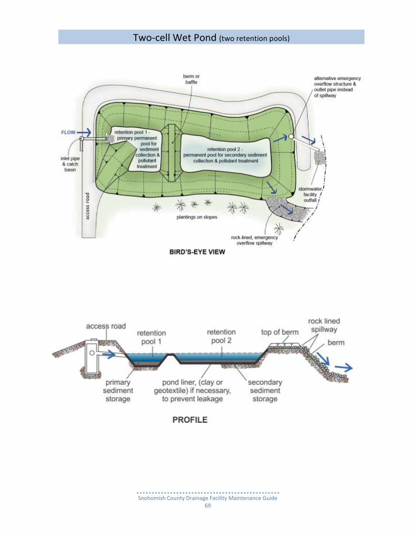
Snohomish County Drainage Facility Maintenance Guide
69
Two-cell Wet Pond (two retention pools)

Snohomish County Drainage Facility Maintenance Guide
70
Single-cell Wet/Detention Pond (Retention Pool Combined with a Det. Pool)

Snohomish County Drainage Facility Maintenance Guide
71
Two-cell Wet/Detention Pond (Two Retention Pools Combined with Det. Pool)

Snohomish County Drainage Facility Maintenance Guide
72
2 celled deep Water Quality Pond with cell dividing berm and rock walls on three sides– cell 1 is on left for sediment collection
Before Maintenance: 2 celled shallow Water Quality Pond with cell dividing berm – cell 1 is on right of berm for sediment collection
After maintenance: Cell 1 on left
2 celled deep Water Quality Pond – cell 1 in the back is for sediment collection, cell 2 in front has access road to cell 1 running through it and over the cell dividing berm
2 celled Water Quality Pond – cell for sediment collection is undergoing dredging for removal of sediment and cattail root mass
Water Quality Treatment / Detention Pond

Snohomish County Drainage Facility Maintenance Guide
73
2 celled deep Water Quality Pond with concrete cell divider and perimeter walls – cell 1 in the front is for sediment collection.
Close-up of submerged concrete block (known as “ecology block”) cell divider wall
2 celled deep Water Quality Pond with concrete cell divider and perimeter walls during non-routine maintenance of dredging and cattail removal
After maintenance
Water Quality Treatment / Detention Pond
2 celled deep Water Quality Pond with concrete perimeter walls & ecology block cell divider wall

Snohomish County Drainage Facility Maintenance Guide
74
Wet Pond
Drainage system feature
Potential defect
Conditions when maintenance is needed
Results expected when maintenance is performed
or not needed
General Site Conditions Surrounding Pond
Trash and debris accumulation
Site generally littered with debris and Evidence of dumping trash and debris.
Trash and debris removed from site.
Neighbors notified that dumping is prohibited.
“No dumping” sings installed.
Poisonous vegetation and noxious weeds
Any poisonous or nuisance vegetation which may constitute a hazard to maintenance personnel or the public.
Poisonous vegetation eliminated.
NOTE: Any evidence of noxious weeds as defined by the Snohomish County Noxious Weed Control Board requires eradication based on the Board’s recommendation of Herbicide application or by mechanical means.
NOTE: Complete eradication of noxious weeds may not be possible. Compliance with State and County Noxious Weed Control Boards are required.
Contaminants and pollutants
Any evidence of oil, gasoline, contaminants or other pollutants in or near the pond area. For hazardous material, call 911 and Snohomish County SWM.
Contaminants or pollutants removed.
Beaver dams Dam in Flow Control Structure, either in pond, or downstream of facility results in change of function of the facility. NOTE: Coordinate trapping of beavers and removal of dams with appropriate state and county permitting agencies.
Facility fully functional.
Rodent holes Evidence of rodent holes on site, but not in pond area.
Rodents eliminated.

Snohomish County Drainage Facility Maintenance Guide
75
Drainage system feature
Potential defect
Conditions when maintenance is needed
Results expected when maintenance is performed
or not needed
General Site Conditions Surrounding Pond
Insects Insects such as wasps and hornets interfere with maintenance activities. NOTE: Apply insecticides in compliance with manufacturer’s directions.
Insects eliminated.
Tree growth and hazard trees
Specific trees hinder maintenance access or interfere with maintenance activity (i.e., slope mowing, silt removal, vactoring, or equipment movements.
Only trees hindering maintenance activities removed.
Hazard trees (dead, diseased, or dying) are identified. NOTE: A certified arborist should be consulted to determine health of tree or removal requirements.
Hazard trees removed.
NOTE: Harvested trees should be recycled into mulch or other beneficial uses (e.g., alders for firewood).
Pond cell Side Slopes (natural or excavated)
Tree growth Trees growing below pond Emergency Overflow elevation subject to blowing over, uprooting the root wad due to water saturated soil. An exposed wad and hole in left in the soil can be a major source of continued erosion.
Trees removed.
Roots removed as necessary.
Pond Cell Side Slopes (natural or excavated)
Erosion Eroded damage over 2 inches deep where cause of damage is still present or where there is potential for continued erosion.
Any erosion observed on a compacted berm embankment.
NOTE: A licensed civil engineer should
be consulted to resolve source of erosion.
Slopes should be stabilized using appropriate erosion control measure(s); e.g., rock reinforcement, planting of grass, compaction.

Snohomish County Drainage Facility Maintenance Guide
76
Drainage system feature
Potential defect
Conditions when maintenance is needed
Results expected when maintenance is performed
or not needed
Pond Perimeter & Cell Divider Concrete Walls
Cracks, holes, scaling & steel structural reinforcement bars (rebar) exposed
Professional inspection determines that wall(s) is not structurally sound or leaks are present.
Wall(s) repaired and structurally sound, or replaced.
Pond Cell(s)
Excessive sediment accumulation
Accumulation exceeds 10% of as-built pond cell depth.
Sediment accumulation removed.
As-built depth and shape of pond cell re-established.
Pond reseeded as necessary to control erosion.
Permanent water pool leaking out of cell
One or both cell pools are empty.
Pond cells must have a pool of water to remove pollutants. NOTE: A leaking pond cell needs to be lined or re-lined with non porous material (fabric or clay) 1 foot below cell bottom (floor). NOTE: A licensed civil engineer should be consulted to determine problem and design a solution.
Cell(s) lined to prevent water pool from leaking out.
Tree growth Trees growing on any portion of pond bottom NOTE: A licensed geotechnical engineer should be consulted to determine if roots need to be removed.
Trees removed.
Roots removed as necessary.
Pond Cell(s) Clay or
Exposed or damaged
Portion of liner is visible. Liner is covered with minimum 12” compacted soil.
Geotextile liner is punctured. Puncture(s) repaired or liner replaced as necessary.

Snohomish County Drainage Facility Maintenance Guide
77
Drainage system feature
Potential defect
Conditions when maintenance is needed
Results expected when maintenance is performed
or not needed
Pond Cell(s) Clay or
Exposed or damaged
Clay liner has deep gouge(s). Gouge(s) repaired or liner replaced as necessary.
Pond Perimeter and Cell Divider Structural Berms (Dams) Pond Perimeter and Cell Divider Structural Berms (Dams)
Soil Settlement
Any part of a compacted structural berm which has settled 4 inches lower than the design elevation.
Settling can be an indication of more severe problems with the berm or outlet works. NOTE: If settlement is apparent, measure berm to determine amount of settlement. NOTE: A licensed civil engineer should be consulted to determine the source of the settlement.
Berm is repaired and returned to design elevation.
Tree Growth Trees growing on any portion of pond interior and exterior slopes as well as the top
Trees removed
Roots removed as necessary.
Slopes stabilized.
Piping Discernable water flow through a compacted structural berm due to tree roots and/or rodent holes/tunnels, can lead to erosion within a berm and structural failure. NOTE: A Geotechnical engineer should be consulted to inspect, evaluate, and recommend a repair solution plan. NOTE: If pond volume exceeds 10 acre-feet, coordinate with the Road Maintenance division of Snohomish County Public Works Department and the State Department of Ecology.
Piping eliminated. Erosion potential resolved.

Snohomish County Drainage Facility Maintenance Guide
78
Drainage system feature
Potential defect
Conditions when maintenance is needed
Results expected when maintenance is performed
or not needed
Emergency Overflow Spillway
Rock armoring missing
Rock layer on sub-grade is less than 1.0’ deep and sub-grade is exposed.
Rock depth restored to design depth of 1.0’.
Erosion Eroded damage over 2 inches deep where cause of damage is still present or where there is potential for continued erosion.
Slopes should be stabilized using appropriate erosion control measure(s); e.g., rock reinforcement, planting of grass, compaction.
Any erosion observed on a compacted structural berm embankment. NOTE: licensed civil engineer should be consulted to inspect, evaluate, and recommend a repair plan.
Snohomish County Drainage Facility Maintenance Guide
79
Wet Vault
What is a Wet Vault? A Wet Vault is an underground rectangular reinforced concrete tank which collects and removes pollutants from stormwater runoff originating from impervious surfaces such streets, sidewalks, driveways, parking lots and roofs through pipes or drainage ditches.
The runoff is conveyed to a Wet Vault either by a pipe system, ranging in diameter from 8” to 30”, or combined drainage ditch and pipe system.
Wet Vaults are usually located at the lowest area on a site and as close as possible to a natural water body (stream, wetland, lake or Puget Sound) or an engineered drainage system to discharge into.
Vaults are a convenient structure on which to place an outdoor sports court, play field or play equipment over the top of a vault lid.
How does a Wet Vault work? Pollutants, such as trace metals from cars and trucks, nutrients from fertilizers, sediments and organics, are suspended or dissolved in the runoff flowing into a Wet Vault. The Wet Vault, unlike a Wet Pond, removes only sediment and some trace metals as storm runoff mixes with the water in a vault’s permanent pool.
The only pollutant removal mechanism is the settling out of suspended (floating) pollutant particles in stormwater runoff that are then deposited on the permanent pool bottom.
A less significant portion of pollutants are removed when runoff enters the vault en masse (as a flood) and displaces the existing water retained in the vault’s permanent pool.
The Wet Vault is designed to collect stormwater during the rainy season and store it as a semi-permanent pool. This pool is commonly called a wet pool or dead storage area.
When stormwater runoff is conveyed to the vault, it mingles with the stormwater in the wet pool. As this occurs, a portion of the pollutants which are either dissolved in the stormwater or attached to sediment particles, settle out and accumulate on the vault bottom.
During storm events Wet Vaults slowly discharge the runoff, less whatever pollutants have been filtered out into the dead storage area, through a Flow Control Structure outlet.
The flow is regulated (restricted) to prevent downstream property damage as well as fish and wildlife poisoning and destruction of habitat associated with downstream water bodies.
Wet Vault design In Snohomish County, the most common type of Wet Vault design is a “permanent” pollutant removal pool of water combined with an additional pool of stormwater runoff temporarily “stacked” (detained) on top of the “permanent” pool for flood control and erosion reduction purposes. In essence, the vault is both a retention and detention facility.
Being underground, the Wet Vault lacks the biological pollutant removal mechanisms that would be present in a Wet Pond.
o This effectively eliminates the possibility of removing dissolved pollutants such as soluble nutrients found in fertilizers or trace metals such as copper from automobiles.
o However, the primary pollutant removal mechanism of settling out of suspended (floating) pollutant particles attached to sediment particles and being deposited on the vault floor is viable.

Snohomish County Drainage Facility Maintenance Guide
80
Vault configurations o The most common configuration in Snohomish County utilizes the entire vault as a single cell for
both the “permanent” pollutant laden sediment removal pool plus the temporary flood control storage pool stacked on top.
o A less common configuration is having the bulk of pollutant laden sediment collection taking place in a separate cell or forebay at the upstream end of the vault. The forebay can take up to 25% of the vault’s volume. This allows
Cleaner runoff to collect in the primary cell before being discharged downstream, and Easier/less costly maintenance with most of the sediment collected in a more compact
space.
With either single or double cell configuration (forebay plus primary cell), there is a o Permanent pollutant removing pool from end to end of the vault, single cell or with a primary
cell plus the additional forebay, and also a o Temporary flood control pool stacked on top of the pollutant removal pool.
The additional temporary stormwater runoff capacity is slowly released through a Flow Control Structure as the outlet to a natural or engineered stormwater system.
o The flow out is designed to completely drain the temporary capacity within 24-48 hours after a storm event has lessened considerably or ceased, down to the top of the dead storage volume.
Common maintenance needs Eventually the sediment and other pollutants will have to be removed because the accumulation reduces the storage capacity of the vault.
Remove trash and vegetation debris
Prevent vault and pipe system clogging
Sediment removal
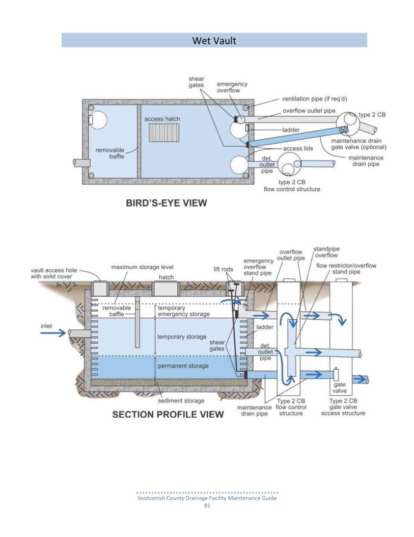
Snohomish County Drainage Facility Maintenance Guide
81
Wet Vault

Snohomish County Drainage Facility Maintenance Guide
82
Wet Vault With Sport Court On Top
Normal dual use of a Water Quality Vault with an asphalt game court, play set and lawn placed on top – all four photos of same vault

Snohomish County Drainage Facility Maintenance Guide
83
Water Quality (Wet) Vault
Drainage system feature
Potential defect
Conditions when maintenance is needed
Results expected when maintenance is performed
or not needed
Vault Chamber(s)
Floating debris accumulation
Any debris accumulated in vault, pipe or inlet/outlet.
All floating debris removed.
Sediment and non-floating debris accumulation
Accumulation on bottom exceeds 6-inches.
All sediment and debris removed from bottom.
Plugged or damaged pipes
Inlet/outlet pipe(s) plugged, damaged or broken and needs repair.
Pipe unplugged, repaired and/or replaced.
Vault Concrete Lid
Access hole cover damaged/not working or missing
Cover cannot be opened or removed, especially by one person. Missing cover is safety hazard.
Cover repaired or replaced.
Vault Bottom, Walls & Lid
Cracks, holes, scaling & steel structural reinforcement bars (rebar) exposed
Professional inspection determines that vault is not structurally sound or leaks are present.
Vault repairs or replaced made so that it meets design specifications and is structurally sound.
Cracks wider than 1/2-inch at the joint of any inlet/outlet pipe or evidence of soil particles entering through the cracks.
Cracks repaired and no cracks exist wider than 1/4-inch.
Baffles Signs of structural failure
Baffles corroding, cracking, warping and/or showing signs of failure as determined by maintenance/inspection staff.
Baffles repaired or replaced to specifications.
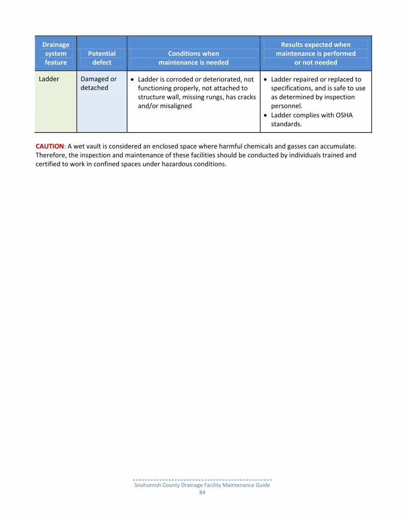
Snohomish County Drainage Facility Maintenance Guide
84
Drainage system feature
Potential defect
Conditions when maintenance is needed
Results expected when maintenance is performed
or not needed
Ladder Damaged or detached
Ladder is corroded or deteriorated, not functioning properly, not attached to structure wall, missing rungs, has cracks and/or misaligned
Ladder repaired or replaced to specifications, and is safe to use as determined by inspection personnel.
Ladder complies with OSHA standards.
CAUTION: A wet vault is considered an enclosed space where harmful chemicals and gasses can accumulate. Therefore, the inspection and maintenance of these facilities should be conducted by individuals trained and certified to work in confined spaces under hazardous conditions.

Snohomish County Drainage Facility Maintenance Guide
85
Biofiltration Swale
What is a Biofiltration Swale? Biofiltration Swales (Bioswales) have been the engineered method of choice since the early 1990s to meet Snohomish County requirements for reducing the amount of sediment and automobile related pollutants entering streams and lakes from real estate development and public road projects. They use grasses and plants in channels for stormwater runoff to filter through, capture pollutants and biologically degrade them. Biofiltration Swales can be either a stand-alone stormwater water quality treatment facility or be incorporated with a variety of stormwater facilities as a component to provide pollutant removal treatment.
How does a Biofiltration Swale work? A Biofiltration Swale uses a carpet of wet/dry and sun/shade tolerant grasses or other densely planted wetland like vegetation to filter out sediment and oily substances.
Most Bioswales remain dry, except during and immediately after a storm event when storm runoff flows through it slowly and at a shallow depth.
As runoff migrates down the swale and passes through the plants, pollutants are removed by the combined effects of filtration, settling and infiltration through soil.
Typical Bioswale design Basic Biofiltration Swale configurations:
A grass lined flat bottom channel from upstream end to downstream end set at a slightly sloped grade (within a range of 1-5% of flat) and
Gently sloping sides o Usually three feet horizontal for each foot of depth) o Ranging in depth from two to eight feet. o Carpeted with grasses or densely planted vegetation
Swales, depending on the nature of the topography, can be either o Straight, or o Gently curved.
Typical channel bottom design:
length of 200 feet, and
minimum width of two feet. Some swales are shorter:
usually not less than 100 feet,
but require a greater width than two feet. As a general rule of thumb, add one foot of width for each 50-foot reduction in length.
Location options when incorporated with a stormwater facility:
preferred - immediately downstream
other – immediately upstream

Snohomish County Drainage Facility Maintenance Guide
86
Biofiltration Swale designs to date Biofiltration Swale designs have evolved since Bioswales began to be incorporated in land development projects in the early 1970s. There have been three distinct design eras, as describe below.
Obsolete - Oldest design (1970s into early 2000s): Biofiltration Swales were excavated out of naturally or artificially compacted soils and were either overlaid with ordinary lawn sod or seeded with lawn grass seed.
Obsolete - Recent design (mid 2000s to 2010): From the mid 2000s to 2010, sod has been laid only to provide a temporary, immediate functioning water quality treatment through the dry season. During early fall, the swale would have been sown with various types grass seed and possibly sedges and rushes that are able to tolerate a specific range of site condition, i.e., wet or dry soils, upland or marshy wetland conditions as well as sun or shade. Current -Accepted design (2010 to present):
Basic Bioswale: Since 2010 Snohomish County has required that in addition to seeding as noted above Biofiltration Swales need to have their channel bottoms and sides over-excavated an additional depth of 12”-18” below their designed finished elevations. The over-excavated area is then filled with approved topsoil with approved compost mixed in (amended). The combination of the depth of compost amended topsoil and site tolerant grass, sedges and rushes allows roots to grow deep and provide a dense carpet of vegetation for stormwater runoff to flow through. As runoff passes through the vegetation at a slow rate due to the swale’s slightly sloped grade, pollutants are removed through the combined effects of filtration (through the grass), infiltration (through the soil) and settling (if the swale is designed to for extended periods of inundation. (See Wet Bioswale below)
Wet Bioswale: Utilized when it may be necessary to install an under drain running the full length of the swale in order to avert survival failure of a swale’s vegetation due to extended periods of inundation caused by one or even a combination of the following conditions:
The swale channel bottom slope is less than 1% to flat, causing water to move too slowly, or
A continuous low base flow from either an upstream detention facility or a stormwater runoff conveyance system, is likely to result in saturated soil (especially the compost amended topsoil for infiltration) for long periods of time, or
The groundwater table is too high for long periods of time or even permanently. (NOTE: If the water table rises higher than the flow level of under drain pipe, that renders useless not only the under drain but also the entire swale).
NOTE: Even when an under drain has been installed, the soil in a bioswale and the immediate surrounding area may still become saturated. When this is the case, if vegetation appropriate for a Basic Bioswale has been planted, these species may need to be replaced with vegetation specifically adapted to wet soil conditions.

Snohomish County Drainage Facility Maintenance Guide
87
Basic Bioswale – First Generation Standard (Obsolete)

Snohomish County Drainage Facility Maintenance Guide
88
In residential lot back yard
Along residential street
In retail strip mall parking area median
In residential lot between front yard and street
In residential open space tract
Church parking area
Basic Bioswales – Well Maintained
Basic Bioswales – Poorly Maintained

Snohomish County Drainage Facility Maintenance Guide
89
Basic Bioswales – Never Maintained
Basic Bioswale – Before and After Maintenance
In residential plat native growth protection area (NGPA) tract
In this rural residential open space tract, where’s the bioswale?
Bioswale in extremely narrow space- Before maintenance
After removing all vegetation,

Snohomish County Drainage Facility Maintenance Guide
90
Before maintenance
During maintenance
After maintenance
Basic Bioswales – Before, During and After Maintenance

Snohomish County Drainage Facility Maintenance Guide
91
Basic Bioswale – Current Standard

Snohomish County Drainage Facility Maintenance Guide
92
Wet Bioswale with Under drain – Current Standard
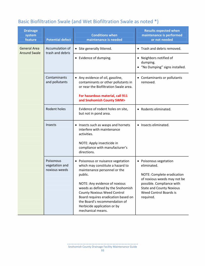
Snohomish County Drainage Facility Maintenance Guide
93
Basic Biofiltration Swale (and Wet Biofiltration Swale as noted *)
Drainage system feature Potential defect
Conditions when maintenance is needed
Results expected when maintenance is performed
or not needed
General Area Around Swale
Accumulation of trash and debris
Site generally littered. Trash and debris removed.
Evidence of dumping. Neighbors notified of dumping.
“No Dumping” signs installed.
Contaminants and pollutants
Any evidence of oil, gasoline, contaminants or other pollutants in or near the Biofiltration Swale area. For hazardous material, call 911 and Snohomish County SWM>
Contaminants or pollutants removed.
Rodent holes Evidence of rodent holes on site, but not in pond area.
Rodents eliminated.
Insects Insects such as wasps and hornets interfere with maintenance activities. NOTE: Apply insecticide in compliance with manufacturer’s directions.
Insects eliminated.
Poisonous vegetation and noxious weeds
Poisonous or nuisance vegetation which may constitute a hazard to maintenance personnel or the public. NOTE: Any evidence of noxious weeds as defined by the Snohomish County Noxious Weed Control Board requires eradication based on the Board’s recommendation of Herbicide application or by mechanical means.
Poisonous vegetation eliminated. NOTE: Complete eradication of noxious weeds may not be possible. Compliance with State and County Noxious Weed Control Boards is required.

Snohomish County Drainage Facility Maintenance Guide
94
Drainage system feature Potential defect
Conditions when maintenance is needed
Results expected when maintenance is performed
or not needed
General Area Around Swale
Tree growth and hazard trees
Specific trees hinder maintenance access or interfere with maintenance activity (i.e., slope mowing, silt removal, vactoring, or equipment movements.
Only trees hindering maintenance activities removed.
Hazard trees (dead, diseased, or dying) are identified. NOTE: A certified arborist should be consulted to determine health of tree or removal requirements.
Hazard trees removed. NOTE: Harvested trees should be recycled into mulch or other beneficial uses (e.g., alders for firewood).
Swale Structural Berm (embankment) Side Slope
Piping Discernable water flow through a compacted structural berm due to tree roots and/or rodent holes/tunnels, can lead to erosion within a berm and structural failure. NOTE: A Geotechnical engineer should be consulted to inspect, evaluate, and recommend a repair solution plan.
Piping eliminated. Erosion potential resolved.
Swale Side Slopes (natural or excavated)
Erosion Eroded damage over 2 inches deep where cause of damage is still present or where there is potential for continued erosion.
Any erosion observed on a compacted berm embankment.
NOTE: A licensed civil engineer
should be consulted to resolve source of erosion.
Slopes should be stabilized using appropriate erosion control measure(s); e.g., rock reinforcement, planting of grass, compaction.

Snohomish County Drainage Facility Maintenance Guide
95
Drainage system feature Potential defect
Conditions when maintenance is needed
Results expected when maintenance is performed
or not needed
Swale Channel Bottom
Standing water Water does not drain freely - standing water in swale between storms.
Any of the following may apply: Sediment or trash blockages removed.
Grade from upstream end to downstream end of swale is level.
Check dams replaced with level spreaders.
Under drain installed as necessary.
If all the above fail, Basic Bioswale is converted to Wet Bioswale.
Flow spreader Flow spreader not uniformly level or clogged so that flows are not evenly distributed across entire swale width.
Flow Spreader leveled.
Clogging eliminated.
Flow spreads evenly over entire swale width.
Constant base flow
Muddy Channel(s) in swale bottom formed by erosion due to continuous flow, even during extended dry periods.
Low-flow pea-gravel drain installed the length of the swale;
Or the base flow was diverted to bypass around swale.
Inlet/outlet (including under
drain)*
Inlet/outlet areas clogged with sediment and/or debris.
Clogging/blockage eliminated.
Poor vegetation coverage
When grass is sparse or bare or eroded patches occur in more than 10% of the swale bottom.
Poor grass cover is determined.
Condition is corrected by re-planting with grass plugs from on site or purchased: Plugs planted in swale bottom at 8-inch intervals;
Or re-seed into loosened, fertile soil.

Snohomish County Drainage Facility Maintenance Guide
96
Drainage system feature Potential defect
Conditions when maintenance is needed
Results expected when maintenance is performed
or not needed
Swale Channel Bottom
Vegetation When the grass becomes excessively tall (greater than 10-inches); when nuisance weeds and other vegetation starts to take over.
Vegetation mowed to 4” height or removed as necessary so that flow not impeded.
Grass clippings removed.
Wetland
vegetation*
Vegetation becomes sparse and does not provide adequate filtration, OR vegetation is crowded out by very dense clumps of cattail, which do not allow water to flow through the clumps.
Determine cause of lack of vigor of vegetation and correct. Replant as needed. For excessive cattail growth, cut cattail shoots back and compost off-site. NOTE: normally wetland vegetation does not need to be harvested unless die-back is causing oxygen depletion in downstream waters.
Excessive shading
Grass growth is poor because sunlight does not reach swale.
Over-hanging limbs trimmed back as much as possible.
Brushy vegetation on adjacent slopes removed as necessary.
Trash and debris accumulation
Trash and debris accumulated in swale bottom.
Trash and debris removed.
Erosion/scouring Eroded or scoured swale bottom due to high flows or channelization forming ruts in channel bottom.
Ruts or bare areas less than 12 inches wide repaired by filling damaged areas with crushed gravel.
Larger areas re-graded and re-seeded.
Smaller bare areas over seeded or planted with grass plugs at 8-inch intervals.
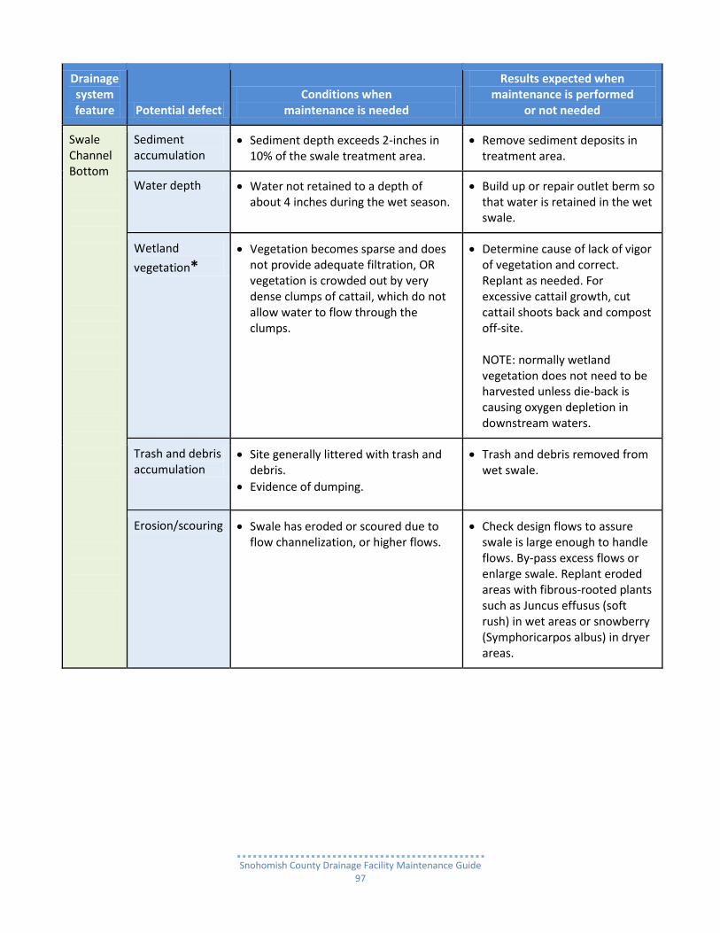
Snohomish County Drainage Facility Maintenance Guide
97
Drainage system feature Potential defect
Conditions when maintenance is needed
Results expected when maintenance is performed
or not needed
Swale Channel Bottom
Sediment accumulation
Sediment depth exceeds 2-inches in 10% of the swale treatment area.
Remove sediment deposits in treatment area.
Water depth Water not retained to a depth of about 4 inches during the wet season.
Build up or repair outlet berm so that water is retained in the wet swale.
Wetland
vegetation*
Vegetation becomes sparse and does not provide adequate filtration, OR vegetation is crowded out by very dense clumps of cattail, which do not allow water to flow through the clumps.
Determine cause of lack of vigor of vegetation and correct. Replant as needed. For excessive cattail growth, cut cattail shoots back and compost off-site. NOTE: normally wetland vegetation does not need to be harvested unless die-back is causing oxygen depletion in downstream waters.
Trash and debris accumulation
Site generally littered with trash and debris.
Evidence of dumping.
Trash and debris removed from wet swale.
Erosion/scouring Swale has eroded or scoured due to flow channelization, or higher flows.
Check design flows to assure swale is large enough to handle flows. By-pass excess flows or enlarge swale. Replant eroded areas with fibrous-rooted plants such as Juncus effusus (soft rush) in wet areas or snowberry (Symphoricarpos albus) in dryer areas.

Snohomish County Drainage Facility Maintenance Guide
98
Vegetated Filter Strip
What is a Vegetated Filter Strip? A Vegetated Filter Strip is a narrow densely carpeted band of low growing vegetation (usually grasses) planted in deep soil, sloping downward from the edge of a paved roadway or parking area that provides a high level of stormwater pollutant removal (treatment). The strip is designed to filter out runoff sediment and automobile related pollutants as runoff sheet flows across pavement and then flows through planted vegetation as well as down through a deep layer of topsoil mixed with compost.
How does a Vegetated Filter Strip work? When stormwater runoff passes through the vegetation, pollutants are removed by the combined effects of Filtering through the vegetation, as well as Infiltrating through the compost enhanced topsoil. These effects are aided by the reduction of runoff velocity as the water leaves the pavement and begins passing through the vegetation.
Typical Vegetated Filter Strip design There are two important elements which make up a Vegetated Filter Strip:
A deep bed of topsoil mixed with approved compost: o to enhance health, growth and survivability of the vegetation, and o to promote deep rooting of the vegetation, and allow for effective infiltration.
The proper downward slope of the strip to insure that the stormwater runoff is flowing through the vegetation at a rate that allows:
o The effective collection/removal of sediment throughout vegetated strip, and o The maximum amount of runoff to infiltrate through the topsoil for the removal of automobile
related pollutants. Often the width of the strip is too narrow for runoff to completely filter through the vegetation. When that is the case, there are two options to transport the excess runoff downstream. Either, a drainage swale or a below ground drainage trench with an under drain, are added at the base of the strip.
Common maintenance needs Frequency: Vegetated Filter Strips should be frequently maintained to sustain their ability to remove sediment and pollutants:
strips along roadways with shoulders more frequently
strips in parking area less frequently. Level of Maintenance:
Along roadways - Filter strips installed along roadways with shoulders require grading to remove sediment, soil, vegetation and debris buildup to provide an even transition from pavement to gravel or dirt shoulder to allow uniform sheet flows coming off the road on to the Filter Strip.
Parking areas - Filter strips in parking areas usually only need the buildup to be vacuumed up or hand shoveled and swept away. Since water takes the path of least resistance, it will flow to the point where there is little or no sediment build up and as that flow becomes more concentrated there will be more erosion occurring at that point. Just a few of these points along a strip will cause a great deal of erosion damage and reduce its pollutant removal function. This level of maintenance will reduce the need for the more difficult and costly repair or replacement of an eroded vegetated strip and drainage channel or a clogged drain trench.

Snohomish County Drainage Facility Maintenance Guide
99
Vegetated Filter Strip
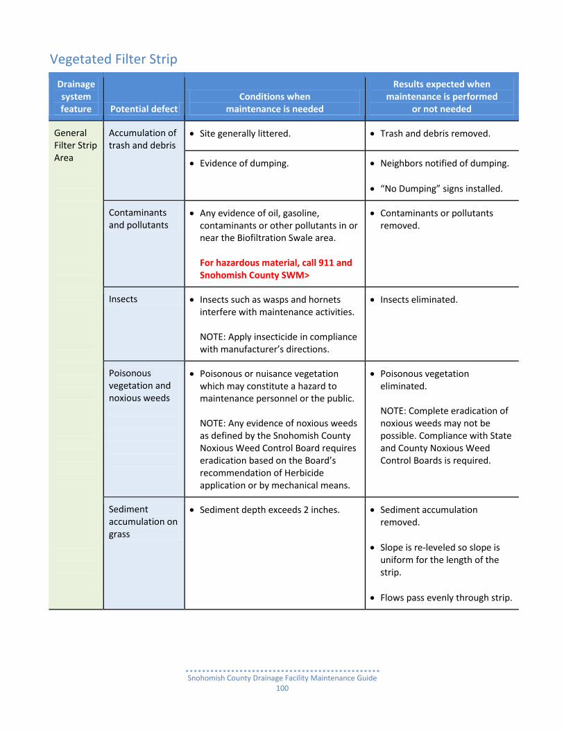
Snohomish County Drainage Facility Maintenance Guide
100
Vegetated Filter Strip
Drainage system feature Potential defect
Conditions when maintenance is needed
Results expected when maintenance is performed
or not needed
General Filter Strip Area
Accumulation of trash and debris
Site generally littered. Trash and debris removed.
Evidence of dumping. Neighbors notified of dumping.
“No Dumping” signs installed.
Contaminants and pollutants
Any evidence of oil, gasoline, contaminants or other pollutants in or near the Biofiltration Swale area. For hazardous material, call 911 and Snohomish County SWM>
Contaminants or pollutants removed.
Insects Insects such as wasps and hornets interfere with maintenance activities. NOTE: Apply insecticide in compliance with manufacturer’s directions.
Insects eliminated.
Poisonous vegetation and noxious weeds
Poisonous or nuisance vegetation which may constitute a hazard to maintenance personnel or the public. NOTE: Any evidence of noxious weeds as defined by the Snohomish County Noxious Weed Control Board requires eradication based on the Board’s recommendation of Herbicide application or by mechanical means.
Poisonous vegetation eliminated. NOTE: Complete eradication of noxious weeds may not be possible. Compliance with State and County Noxious Weed Control Boards is required.
Sediment accumulation on grass
Sediment depth exceeds 2 inches. Sediment accumulation removed.
Slope is re-leveled so slope is uniform for the length of the strip.
Flows pass evenly through strip.

Snohomish County Drainage Facility Maintenance Guide
101
Drainage system feature Potential defect
Conditions when maintenance is needed
Results expected when maintenance is performed
or not needed
General Filter Strip Area
Vegetation When the grass becomes excessively tall (greater than 10-inches); when nuisance weeds and other vegetation starts to take over.
Vegetation mowed to 4” height or removed as necessary so that flow not impeded.
Grass clippings removed.
Poor vegetation coverage
When grass is sparse or bare or eroded patches occur in more than 10% of the swale bottom.
Poor grass cover is determined.
Condition is corrected by re-planting with grass plugs from on site or purchased: Plugs planted in swale bottom at 8-inch intervals;
Or re-seed into loosened, fertile soil.
Trash and debris accumulation
Trash and debris accumulated on the filter strip.
Trash and debris removed.
Erosion/scouring Eroded or scoured areas due to flow channelization.
Ruts or bare areas less than 12 inches wide repaired by filling damaged areas with crushed gravel.
Larger areas re-graded and re-seeded.
Smaller bare areas over seeded or planted with grass plugs at 8-inch intervals.
Erosion Eroded damage over 2 inches deep where cause of damage is still present or where there is potential for continued erosion.
Any erosion observed on a compacted berm embankment.
NOTE: A licensed civil engineer should
be consulted to resolve source of erosion.
Slopes should be stabilized using appropriate erosion control measure(s); e.g., rock reinforcement, planting of grass, compaction.
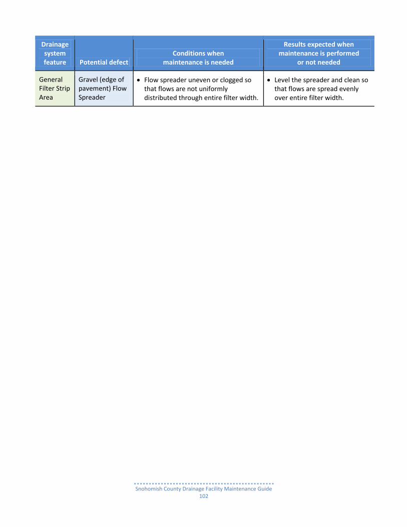
Snohomish County Drainage Facility Maintenance Guide
102
Drainage system feature Potential defect
Conditions when maintenance is needed
Results expected when maintenance is performed
or not needed
General Filter Strip Area
Gravel (edge of pavement) Flow Spreader
Flow spreader uneven or clogged so that flows are not uniformly distributed through entire filter width.
Level the spreader and clean so that flows are spread evenly over entire filter width.

Snohomish County Drainage Facility Maintenance Guide
103
Infiltration Pond
What is an Infiltration Pond? An Infiltration Pond is an earthen basin excavated out of permeable soil for storing stormwater runoff to both provide a small level of flood control and also allow the stored runoff to infiltrate through the pond for pollutant removal and ground water recharge rather than discharge to a downstream surface water drainage system.
How does an Infiltration Pond work? When a pond receives stormwater runoff, the water immediately begins to infiltrate through the pond bottom.
As water collects faster than it can infiltrate and pond volume increases, the runoff will also begin to infiltrate through the sides of a pond.
As runoff percolates through porous soil, the toxicity of various pollutants is depleted.
Eventually the water migrates to ground water, which in turn helps maintain low flow to streams, wetlands and lakes.
During some extreme storm events stormwater can build up to a level that exceeds the pond’s capacity.
When that occurs, an initial overflow structure inside the pond releases the excess water downstream.
If runoff continues to build up and exceed the capacity of the initial overflow structure, water will seep out over a secondary or emergency overflow spillway.
Typical Infiltration Pond design Infiltration Ponds are typically designed in two configurations.
The most common is a single pool (cell) for both collecting stormwater runoff for flood control and soil infiltration for pollutant removal.
The other configuration has a smaller pool or forebay added at the upstream end. o The function of the forebay is two-fold: collect stormwater runoff for flood control purposes and
to remove sediment and other pollutants to reduce the sediment and pollutant load flowing to the larger downstream pool.
o The purpose of the downstream pool is not only for flood control, but also to receive cleaner water allowing it to infiltrate and reduce the amount of contaminants they may migrate to ground water.
Another major design parameter is whether to provide an access road down to the Infiltration Pond bottom or not.
Snohomish County may require that if heavy equipment is necessary for maintenance purposes to rake and/or dredge a pond, the pond should be designed with an access road along the entire pond perimeter. See Common maintenance needs below.
Such a requirement demands that the Infiltration Pond system be designed long and narrow (no more than 30 feet wide at the bottom).
Common maintenance needs Over time, a pond accumulates a sufficient amount of sediment, vegetation debris and man-made trash which covers the porous soil, as well as clogs pipe inlets and outlets or an under drain system (if required) and flow control structure (if required). This reduces the Infiltration Pond’s infiltration performance and is a major concern.

Snohomish County Drainage Facility Maintenance Guide
104
Preventing covering or icing (as on a cake) of the porous soil with sediment is an on-going maintenance operation.
The removal of sediment is usually required every several years.
Removing vegetation debris and man-made trash as well as unwanted vegetation growth (trees, bushes, grass patches) that accumulate or grow on the pond bottom and sides can be necessary two to four times a year.
Soil slumping and compaction are also major concerns. The cause is usually:
The misuse of the pond basin as a recreational area for BMX bike and motorcycle practice tracks and ramps, fort building, dog walking, etc., and
The use of large/heavy excavators and other heavy equipment for dredging, raking or vegetation removal. Heavy maintenance equipment should not be used in an Infiltration Pond if the weight of the equipment will compact the porous soil on the pond bottom and sides
The alternative for large and heavy is small and light, which must be operated carefully and not hurried so as not to scar the pond bottom and sides.
For small, “pocket sized” Infiltration Ponds, or larger ones with extremely sensitive soil conditions, raking and/or dredging can be done by hand, as an alternative for using heavy or small equipment.
NOTE: Whether heavy or small equipment is used, all oil and hydraulic fluid spills must be totally removed along with the dredged out material.

Snohomish County Drainage Facility Maintenance Guide
105
Infiltration Pond

Snohomish County Drainage Facility Maintenance Guide
106
Infiltration Pond
Infiltration Pond
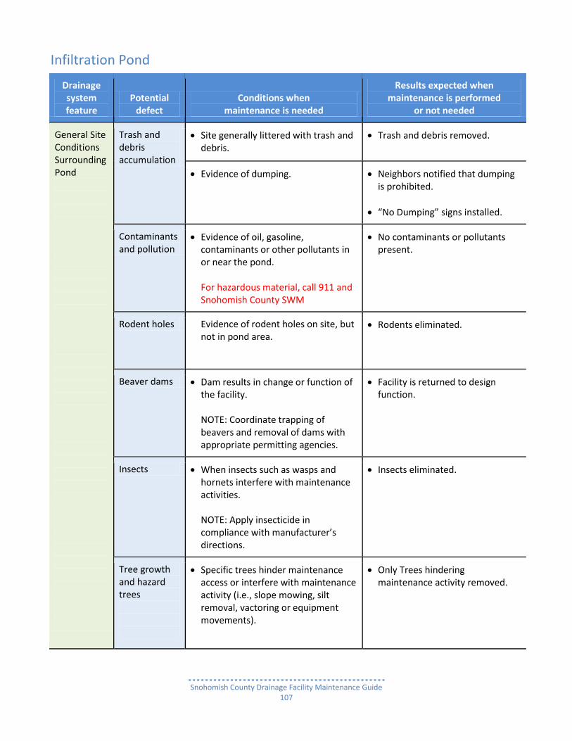
Snohomish County Drainage Facility Maintenance Guide
107
Infiltration Pond
Drainage system feature
Potential defect
Conditions when maintenance is needed
Results expected when maintenance is performed
or not needed
General Site Conditions Surrounding Pond
Trash and debris accumulation
Site generally littered with trash and debris.
Trash and debris removed.
Evidence of dumping. Neighbors notified that dumping is prohibited.
“No Dumping” signs installed.
Contaminants and pollution
Evidence of oil, gasoline, contaminants or other pollutants in or near the pond. For hazardous material, call 911 and Snohomish County SWM
No contaminants or pollutants present.
Rodent holes Evidence of rodent holes on site, but not in pond area.
Rodents eliminated.
Beaver dams Dam results in change or function of the facility. NOTE: Coordinate trapping of beavers and removal of dams with appropriate permitting agencies.
Facility is returned to design function.
Insects When insects such as wasps and hornets interfere with maintenance activities. NOTE: Apply insecticide in compliance with manufacturer’s directions.
Insects eliminated.
Tree growth and hazard trees
Specific trees hinder maintenance access or interfere with maintenance activity (i.e., slope mowing, silt removal, vactoring or equipment movements).
Only Trees hindering maintenance activity removed.

Snohomish County Drainage Facility Maintenance Guide
108
Drainage system feature
Potential defect
Conditions when maintenance is needed
Results expected when maintenance is performed
or not needed
General Site Conditions Surrounding Pond
Tree growth and hazard trees
Hazard trees (dead, diseased, or dying) are identified. NOTE: A certified arborist should be consulted to determine health of tree or removal requirements.
Hazard trees removed.
NOTE: Harvested trees should be recycled into mulch or other beneficial uses (e.g., alders for firewood).
Pond Side Slopes (natural or excavated)
Erosion
Eroded damage over 2 inches deep where cause of damage is present or where there is potential for continued erosion. NOTE: A licensed civil engineer should be consulted to determine the source of the settlement.
Slopes stabilized using appropriate erosion control measure(s); e.g., rock reinforcement, planting grass.
Berm is repaired and stabilized or replaced if necessary according to original design or County approved redesign by licensed civil engineer.
Tree growth Trees growing below pond Emergency Overflow elevation subject to blowing over, uprooting the root wad due to water saturated soil. An exposed wad and hole in left in the soil can be a major source of continued erosion.
Trees removed.
Roots removed as necessary.
Piping Discernable water flow through pond berm. Ongoing erosion with potential for erosion to continue. NOTE: A Geotechnical engineer should be called in to inspect and evaluate condition and recommend repair of condition.
Piping eliminated.
Erosion potential resolved.

Snohomish County Drainage Facility Maintenance Guide
109
Drainage system feature
Potential defect
Conditions when maintenance is needed
Results expected when maintenance is performed
or not needed
Pond Perimeter Structural Berms (Dams)
Soil Settlement
A portion of structural berm (compacted earthen embankment) has settled 4 inches lower than the as-built elevation.
Any part of berm which has settled 4 inches lower than the as-built elevation.
Estimate amount of settlement. Settling can be an indication of more severe problems with the berm.
If settlement is apparent, measure berm to determine amount of settlement.
Settling can be an indication of more severe problems with the berm or outlet works. NOTE: A licensed civil engineer should be consulted to determine the source of the settlement.
Berm is repaired and returned to as-built elevation.
Piping Discernable water flow through a compacted structural berm due to tree roots and/or rodent holes/tunnels, can lead to erosion within a berm and structural failure. NOTE: A Geotechnical engineer should be consulted to inspect, evaluate, and recommend a repair solution plan. NOTE: If pond volume exceeds 10 acre-feet, coordinate with the Road Maintenance division of Snohomish County Public Works Department; and State Department of Ecology, Dam Safety Office.
Piping and erosion eliminated.
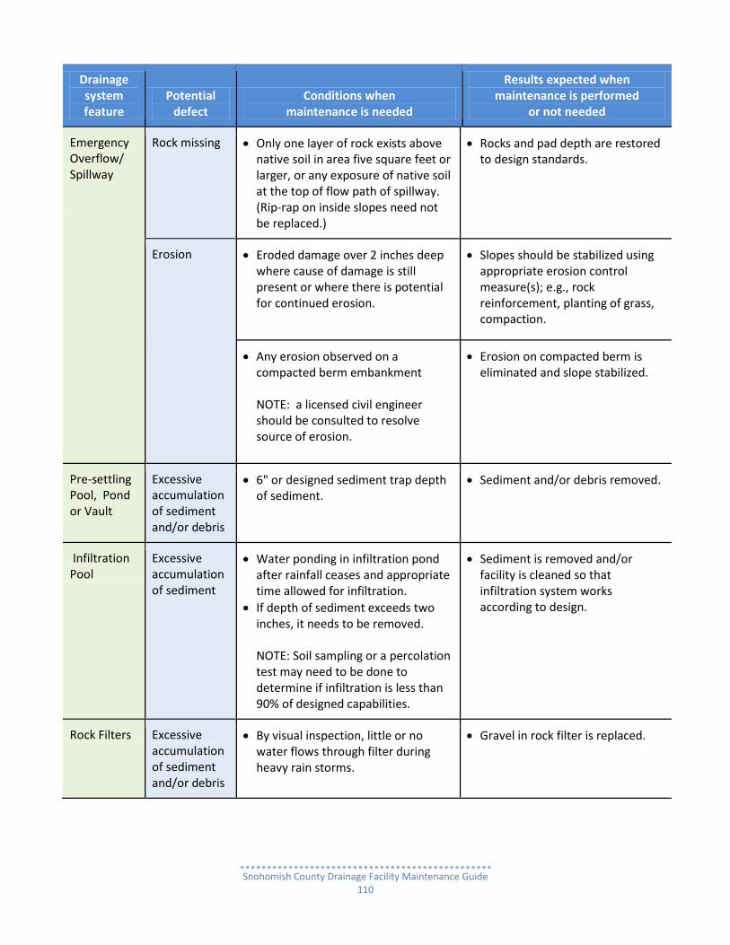
Snohomish County Drainage Facility Maintenance Guide
110
Drainage system feature
Potential defect
Conditions when maintenance is needed
Results expected when maintenance is performed
or not needed
Emergency Overflow/ Spillway
Rock missing
Only one layer of rock exists above native soil in area five square feet or larger, or any exposure of native soil at the top of flow path of spillway. (Rip-rap on inside slopes need not be replaced.)
Rocks and pad depth are restored to design standards.
Erosion
Eroded damage over 2 inches deep where cause of damage is still present or where there is potential for continued erosion.
Slopes should be stabilized using appropriate erosion control measure(s); e.g., rock reinforcement, planting of grass, compaction.
Any erosion observed on a compacted berm embankment
NOTE: a licensed civil engineer should be consulted to resolve source of erosion.
Erosion on compacted berm is eliminated and slope stabilized.
Pre-settling Pool, Pond or Vault
Excessive accumulation of sediment and/or debris
6" or designed sediment trap depth of sediment.
Sediment and/or debris removed.
Infiltration Pool
Excessive accumulation of sediment
Water ponding in infiltration pond after rainfall ceases and appropriate time allowed for infiltration.
If depth of sediment exceeds two inches, it needs to be removed. NOTE: Soil sampling or a percolation test may need to be done to determine if infiltration is less than 90% of designed capabilities.
Sediment is removed and/or facility is cleaned so that infiltration system works according to design.
Rock Filters Excessive accumulation of sediment and/or debris
By visual inspection, little or no water flows through filter during heavy rain storms.
Gravel in rock filter is replaced.
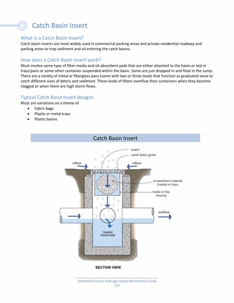
Snohomish County Drainage Facility Maintenance Guide
111
Catch Basin Insert
What is a Catch Basin Insert? Catch basin inserts are most widely used in commercial parking areas and private residential roadway and parking areas to trap sediment and oil entering the catch basins.
How does a Catch Basin Insert work? Most involve some type of filter media and oil-absorbent pads that are either attached to the basin or laid in trays/pans or some other container suspended within the basin. Some are just dropped in and float in the sump. There are a variety of metal or fiberglass pans (some with two or three levels that function as graduated sieve to catch different sizes of debris and sediment. These kinds of filters overflow their containers when they become clogged or when there are high storm flows.
Typical Catch Basin Insert designs Most are variations on a theme of
Fabric bags
Plastic or metal trays
Plastic basins
Catch Basin Insert

Snohomish County Drainage Facility Maintenance Guide
112
3-Tray Catch Basin Insert
Top Tray
Bottom Tray
Catch Basin Insert

Snohomish County Drainage Facility Maintenance Guide
113
Catch Basin Insert
Drainage system feature
Potential defect
Conditions when maintenance is needed
Results expected when maintenance is performed
or not needed
General Sediment accumulation
When sediment forms a cap over the insert media of the insert and/or unit.
No sediment cap on the insert media and its unit.
Trash and debris accumulation
Trash and debris accumulates on insert unit creating a blockage/restriction.
Trash and debris removed from insert unit.
Runoff freely flows into catch basin.
Media Insert- not removing oil
Water flowing out from insert has visible oil sheen.
Water flowing out from insert is free of oils and has no visible sheen.
Media Insert- water saturated
Insert saturated with water - no longer has capacity to absorb.
Replace insert.
Media Insert- oil saturated
Insert saturated with oil, due to a petroleum spill or dump, draining to catch basin.
Determine source.
Clean catch basin.
Replace insert.
Media Insert- use beyond normal product life
Media has been used beyond the typical average life of media insert product.
Replace insert at regular intervals, according to manufacturer’s directions.
Catch Basin
All potential defects
See Catch Basin.
Snohomish County Drainage Facility Maintenance Guide
114
Fencing and Gates
What is the need for a fence? Six foot high galvanized chain-link security fencing and maintenance access gates are required by Snohomish County Code.
For reasons of: o safety to prevent injury, and o security to prevent malicious damage that may impair the function of a facility.
To enclose stormwater facilities that are either: o a steep sloped open stormwater detention/retention pond/swale, or o a concrete vault with tall exposed walls from the top of the vault lid (creating a ledge) to ground
level.
In some cases, after a developer has relinquished responsibility for a project with a stormwater facility that was not required by Snohomish County to have a fence around it, the new owner’s liability insurance may require fencing.
Typical Fence design Galvanized chain-link fences are to be:
six feet high, and
located along the perimeter at the: o top of earthen bank of a pond or swale with:
a pool side slope steeper than 1.0’ vertical for every 3.0’ horizontal a pool with a full water depth exceeding 3.0’
o top of a concrete, block or rock wall of a pond or swale that is exposed more than 3.0’ o edge of a concrete vault lid on top of a wall exposed more than 3.0’
Notes: The County has selected chain-link fencing because:
It not only prevents animals and unauthorized people from entering;
It also allows the pond to be open to view. o Any unauthorized activity within the fenced off area can be witnessed. o This would be difficult if the fence were a wood or plastic wall.
The width of a 16’-20’ wide double hung gate is necessary:
To adequately accommodate maintenance machinery and vehicles.
In some instances there may be a need for: o an additional four foot wide person gate. o In rare instances, a person gate is the only access necessary if the facility merely requires
maintenance and repair by hand.
Common maintenance needs Fence maintenance is a Safety and Security issue. A stormwater facility is considered an “attractive nuisance.”
Over time trees fall on fences, soil erodes away from post holes, vandals cut the wire, tree trunks or limbs push the fence over or lift it up.
These are but several problems which need to be checked out routinely and maintenance action taken immediately.

Snohomish County Drainage Facility Maintenance Guide
115
6’ high black vinyl coated chain-link fence along perimeter of a Detention Pond
6” high black vinyl coated chain-link fence attached to inside face of concrete wall of Water Quality Pond
6’ & 4’ high galvanized chain-link fence with posts set in top of Water Quality Pond perimeter wall
6’ high galvanized chain-link fence with posts set in top of Water Quality Pond Access Road wall
6’ high x 8’ wide galvanized chain-link double hung gate
6’ high x 8’ wide galvanized chain-link double hung gate
Fencing and Gates

Snohomish County Drainage Facility Maintenance Guide
116
Fencing and Gates
Drainage system feature
Potential defect
Conditions when maintenance is needed
Results expected when maintenance is performed
or not needed
Site Erosion Erosion has resulted in an opening under a fence that allows entry to people or pets.
Replace soil under fence so that no opening exceeds 4 inches in height.
Fences Damaged parts
Posts out of plumb more than 6 inches. Post plumb to within 1-1/2 inches of plumb.
Top rails bent more than 6 inches. Top rail free of bends greater than 1 inch.
Any part of fence (including posts, top rails, and fabric) more than 1 foot out of design alignment.
Fence is aligned and meets design standards.
Missing or loose tension wire. Tension wire in place and holding fabric.
Missing or loose barbed wire that is sagging more than 2-1/2 inches between posts.
Barbed wire in place with less than ¾ inch sag between posts.
Extension arm missing, broken, or bent out of shape more than 1-1/2 inches.
Extension arm in place with no bends larges than ¾ inch.
Deteriorated paint or protective coating
Part or parts that have a rusting or scaling condition that has affected structural adequacy.
Structurally adequate posts or parts with a uniform protective coating.
Openings in fabric
Openings in fabric are such that an 8 inch diameter ball could fit through.
No openings in fabric.
Gates
Locking mechanism damaged or missing
Mechanism cannot be opened by one maintenance person.
Locking mechanism repaired or replaced.
Damaged or missing components
Broken or missing hinges such that gate cannot be easily opened and closed by a maintenance person.
Hinges intact and lubed. Gate working freely.
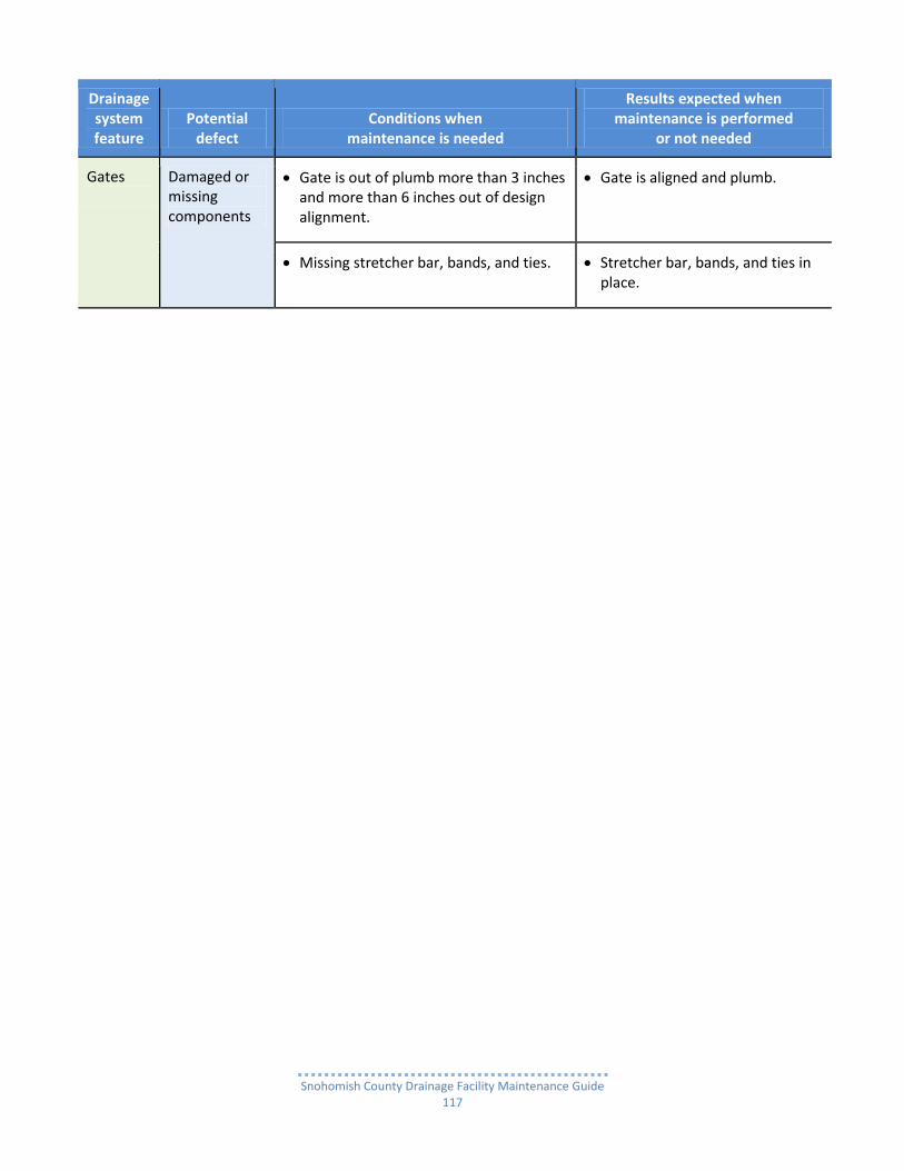
Snohomish County Drainage Facility Maintenance Guide
117
Drainage system feature
Potential defect
Conditions when maintenance is needed
Results expected when maintenance is performed
or not needed
Gates
Damaged or missing components
Gate is out of plumb more than 3 inches and more than 6 inches out of design alignment.
Gate is aligned and plumb.
Missing stretcher bar, bands, and ties. Stretcher bar, bands, and ties in place.

Snohomish County Drainage Facility Maintenance Guide
118
Stormwater Facility Access
Drainage Easements & Covenants Privately owned stormwater facilities are located in:
tracts of land dedicated solely for drainage purposes,
easements across residential lots or tracts of land dedicated for purposes other than drainage,
or as in the case of many commercial properties, they are in neither a tract nor an easement. The ability to access and what parties have responsibility for maintenance of stormwater runoff facilities, including pipe or ditch conveyance systems located outside of the public road right of way, is a somewhat complex issue in Snohomish County. Since the early-mid 1990s, nearly all residential plat home owners associations (HOAs), or all the individual lot owners within a plat if there is no active HOA, are both:
the owners of the stormwater facilities in their plat and,
responsible for their timely inspection and maintenance.
In addition, since 2000 the County has required a Drainage Covenant between it and the owner/developer of a newly developed property with a drainage system and their assigns (future purchasers). For a residential plat the assign would be the HOA and for a condominium project it would be the condo association (CA). This covenant establishes not only a property owner’s, HOA’s/CA’s ownership of any stormwater facility or conveyance system in a drainage easement dedicated to the County, but also the responsibility for inspecting and maintaining them. Even though the drainage easement is dedicated to the County, it only grants the County the right of access to inspect or maintain at its discretion, but no responsibility for inspecting or maintaining a facility/system. Residential plat inspection and maintenance responsibilities are delineated in three documents:
Snohomish County Code (SCC),
the Final Plat Document which outlines the responsibilities of all parties having any interest in the plat, and
the Covenants, Conditions and Restrictions (CC & Rs) which outlines the responsibilities of all property owners.
NOTE: Commercial property owners (including condominium and low density multi-family residential projects) have always owned and been responsible for the inspection and maintenance of their stormwater facilities.
Stormwater Facility Access Roads Many stormwater runoff facilities have access roads to and into a stormwater facility. The roads need to be maintained so that maintenance vehicles and heavy equipment have an unobstructed path to any area needing maintenance or repair. Most pond type facilities have roads (more like driveways) extending from the street to the top rim of the pond. In addition many have roads that continue on top of a pond perimeter structural fill berm along the entire perimeter or only so far as the location of the Flow Control Structure. Some detention ponds have roads that go down into the pond itself so that heavy excavation equipment and dump trucks can have easier access in and out of especially deep ponds. Most of the Access Roads in urban areas are asphalt and most in rural areas are gravel. They should be maintained for ease of inspection and ease of maintenance equipment access. NOTE: See Infiltration Pond for special access road requirements.

Snohomish County Drainage Facility Maintenance Guide
119
Water Quality Pond asphalt access road before maintenance
After maintenance
Water Quality Pond gravel access road before maintenance
After maintenance
Gravel/dirt access road into bottom of Water Quality Pond cell 2 going over berm between cell 2 and cell 1
Access road behind gate completely overgrown with trees and vegetation making it impossible to open gate.
Stormwater Facility Access Roads

Snohomish County Drainage Facility Maintenance Guide
120
Stormwater Facility Access
Drainage system feature
Potential defect
Conditions when maintenance is needed
Results expected when maintenance is performed
or not needed
General Access Conditions
Exposed soil
Soils are bare or eroded. Ground reseeded or vegetation replanted.
Road surface
Condition of road surface may lead to erosion of the facility or limit access.
Road repaired.
Erosion of ground surface
Noticeable rills are observed in landscaped areas.
Causes of erosion identified.
Erosion eliminated or reduced.
Eroded areas are filled, contoured, and seeded.
Affected areas regarded as necessary.
Trash & debris litter
Accumulation of litter across site. Trash and debris removed.
Poisonous vegetation and noxious weeds
Any poisonous or nuisance vegetation which may constitute a hazard to maintenance personnel or the public.
Any evidence of noxious weeds as defined by State or local regulations. NOTE: Apply herbicides in accordance with requirements of Snohomish County Noxious Weed Board.
Poisonous vegetation eliminated. NOTE: Complete eradication of noxious weeds may not be possible. Compliance with State or local eradication policies required.
Tree growth and hazard trees
Specific trees hinder maintenance access or interfere with maintenance activity (slope mowing, silt removal, vactoring, or equipment movements).
Only trees hindering maintenance activities removed.
Dead, diseased, or dying trees identified.
NOTE: Use a certified Arborist to determine health of tree or removal.
Hazard trees removed. NOTE: Harvested trees should be recycled into mulch or other beneficial uses (e.g., alders for firewood).
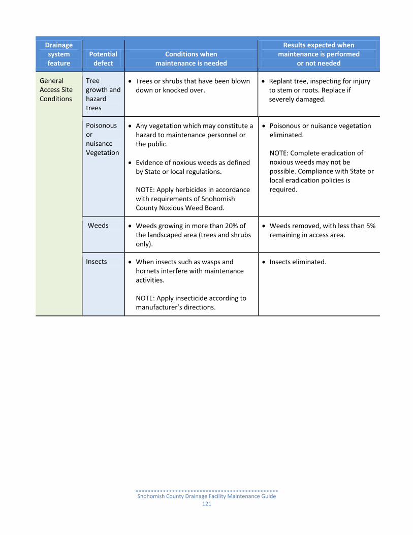
Snohomish County Drainage Facility Maintenance Guide
121
Drainage system feature
Potential defect
Conditions when maintenance is needed
Results expected when maintenance is performed
or not needed
General Access Site Conditions
Tree growth and hazard trees
Trees or shrubs that have been blown down or knocked over.
Replant tree, inspecting for injury to stem or roots. Replace if severely damaged.
Poisonous or nuisance Vegetation
Any vegetation which may constitute a hazard to maintenance personnel or the public.
Evidence of noxious weeds as defined by State or local regulations. NOTE: Apply herbicides in accordance with requirements of Snohomish County Noxious Weed Board.
Poisonous or nuisance vegetation eliminated. NOTE: Complete eradication of noxious weeds may not be possible. Compliance with State or local eradication policies is required.
Weeds Weeds growing in more than 20% of the landscaped area (trees and shrubs only).
Weeds removed, with less than 5% remaining in access area.
Insects When insects such as wasps and hornets interfere with maintenance activities. NOTE: Apply insecticide according to manufacturer’s directions.
Insects eliminated.
Snohomish County Drainage Facility Maintenance Guide
122
General Grounds Keeping and Landscape Plantings Care
Integral part of stormwater facility maintenance program Establishing a Grounds Keeping and Landscape Plantings Care plan should not only be an integral part of any residential subdivision or commercial property stormwater facility maintenance program, but should be incorporated into the property management program as well. Depending on a stormwater facility’s function and the overall intent of the project design, general grounds keeping ranges from:
Making a stormwater facility and its surrounding area neat and tidy, to
Keeping the facility and its surroundings wild and natural.
Required care Required grounds keeping and maintenance of landscape plantings care includes:
Cultivating the various desirable plant and tree species essential for a stormwater facility’s function
Eliminating or controlling undesirable species, especially noxious weeds (see below).
Controlling plant and tree growth is an ongoing process throughout the growing season and into the rainy season especially
o on earthen berms and o around physical structures such as concrete flow and overflow structures.
It is also important to keep access roads, gates and fences clear of trees and brush.
Control noxious weeds Noxious weeds need to be eliminated or vigorously controlled.
Common noxious weeds found in or near stormwater runoff facilities include: Knotweeds, Yellow Archangel, Atlantic and English Ivy, Yellow Flag Iris, Fragrant Water Lily and Purple or garden Loosestrife.
The less noxious, but still obnoxious plants and trees also need to be vigorously controlled, such as reed canary grass, blackberry and morning glory vines, scotch broom, cottonwood and alder trees.
For more information about noxious weeds go to the Snohomish County Noxious Weed Board website: o http://www1.co.snohomish.wa.us/Departments/Public_Works/Divisions/Road_Maint/Noxious_
Weeds/control_boards.htm o http://www1.co.snohomish.wa.us/Departments/Public_Works/Divisions/Road_Maint/Noxious_
Weeds/weeds_list.htm
Maintenance for aesthetic reasons encouraged Maintenance for aesthetic reasons, ranging from totally “wild and natural” to totally “manicured” is strongly encouraged but not required.
Going beyond what is only required can not only improve a facility’s appearance but also enhance its function as well.
Taking this approach can help even more to: o Reduce the potential for flooding property, o Provide for a more healthy fish and critter habitat, o Improve residential property values, and o Make commercial property more attractive for clients and customers.

Snohomish County Drainage Facility Maintenance Guide
123
General Grounds Keeping and Landscape Plantings Care
Drainage system feature
Potential defect
Conditions when maintenance is needed
Results expected when maintenance is performed
or not needed
Facility Site
Poisonous or nuisance Vegetation
Any vegetation which may constitute a hazard to maintenance personnel or the public.
Evidence of noxious weeds as defined by State or local regulations. NOTE: Apply herbicides in accordance with requirements of Snohomish County Noxious Weed Board.
Poisonous or nuisance vegetation eliminated. NOTE: Complete eradication of noxious weeds may not be possible. Compliance with State or local eradication policies is required.
Facility Site
Weeds (nonpoisonous)
Weeds growing in more than 20% of the landscaped area (trees and shrubs only).
Weeds present in less than 5% of the landscaped area.
Insect hazard or poisonous vegetation
Any presence of poison ivy or other poisonous vegetation or insect nests.
No poisonous vegetation or insect nests present in landscaped area.
Trash & debris litter
See ponds checklist See ponds checklist.
Erosion of ground surface
Noticeable rills are seen in landscaped areas.
Causes of erosion are identified and steps taken to slow down/spread out the water. Eroded areas are filled, contoured, and seeded.
Trees and Shrubs
Dead or damaged
Limbs or parts of trees or shrubs that are split or broken which affect more than 25% of the total foliage of the tree or shrub.
Trim trees/shrubs to restore shape. Replace trees/shrubs with severe damage.
Trees or shrubs that have been blown down or knocked over.
Replant tree, inspecting for injury to stem or roots. Replace if severely damaged.

Snohomish County Drainage Facility Maintenance Guide
124
Drainage system feature
Potential defect
Conditions when maintenance is needed
Results expected when maintenance is performed
or not needed
Trees or shrubs which are not adequately supported or are leaning over, causing exposure of the roots.
Place stakes and rubber coated ties around young trees/shrubs for support.
Visual Buffer Screen
Missing or broken parts in visual screen
Any gap in screen that permits easy entry to facility
Shrubs replaced to for a solid screen.
Unruly shrubbery and vegetation
Shrubbery is growing out of control or is infested with weeds.
Shrubbery is trimmed and weeded to provide appealing aesthetics. Do not use chemicals to control weeds.