dragon force rg65 assembly instructions by eric rosenbaum · dragon force rg65 assembly...
TRANSCRIPT
Dragon Force RG65 Assembly Instructions
by Eric Rosenbaum The Dragon Force is an RG65, which was developed in a collaborative effort, including Joysway, the builder; Ripmax, the UK importer; and the design and development team of Mike Weston, Mark Dicks, and John Tushingham. The team’s goal was to help Joysway produce a high performance RG65 that could be made available at a relatively low price point, and I believe that the effort was a success. The Dragon Force (DF) is a class-legal RG65, which can be raced in any RG65 event. It is also being raced as a strict one design, and the separate rules for one-design racing can be found at (http://dragonforce65.com). The boat is very well packaged, and it comes almost completely assembled. The electronics are installed, the sheeting is run, and the booms are rigged. All that needs to be done is to assemble the stand, install the keel and rudder, glue the mast sec-tions together, tie on the sails, add batteries, and adjust the sheets. The whole process takes only about two to three hours. The illustrated instruction manual will lead the builder through all the steps, but this article should make the process a bit easier. I have also highlighted the class-legal modifications that will make the boat perform better and last longer.
The box contains a highly preassembled boat, foils, transmitter, stand parts, mast parts, and boom assemblies. Eric Rosen-baum, all photos. When assembling the DF, all you will need are scissors, CA glue, and some thread lock. The kit comes with all the necessary Allen wrenches to secure the ballast, keel, and rudder. Thread lock is optional, but I prefer not to take any chances with los-ing the ballast or the jib-boom counterweight. The first step is to assemble the stand. The long tubes are the legs, and they are secured into the four molded parts with a fric-tion fit. The three shorter tubes span the left and right leg assemblies. The instruction manual has step-by-step photos. The first step in the boat assembly is to install the bulb onto the keel. Place the keel in the bulb slot, and then thump it with the palm of your hand until it is fully seated in the slot. The retaining bolt then goes through the bulb and into the keel. Be sure to use some thread locking fluid so that the bolt stays put. Thread locker comes in two types; one is permanent, and the other allows for disassembly with hand tools. You will want to use the one that allows for disassembly.

The keel’s leading and trailing edges are parallel, so either end can be mounted to the bulb. The ends of the keel, not including the threaded insert, should be sealed to prevent water ingress. If your keel ends are not already sealed, you should do so before proceeding. The top of the keel goes into the slot in the bottom of the hull, and it too is secured with a bolt. I also use thread locker on this bolt, as the keel is not removed very often. The boat is small enough that it is easy to transport with the keel and rig in place. As an aside, the keel box on the DF is really well engineered. It is strong, light, and it keeps the water out of the boat through the use of two gaskets and a slip fitting for the keel slot. You will probably never need to remove the keel box unless you decide to paint the hull, or if you have one of the rare boats that leaks a bit. If a gasket is not properly seated, some water will get into the keel box section of the hull.
Here are all the parts that make up the keel box assembly. To remove the keel box, first remove the mast ram from the top of the box. This is the oval piece with two holes and a central adjustment screw. Then remove the four screws that are located in the small holes in the top of the keel box. Pushing a screwdriver into the slot on the bottom of the keel box will separate the two main pieces.

When you are ready to reassemble the keel box, add some waterproof silicone to the bottom part of the box, as shown above. Place the gaskets in the channels and then slip the bottom part into the hull while holding the boat upright. While still hold-ing the part in place, flip the boat over and add the top portion. The trick is to keep the gasket in the channel, so each part is put in place while its channel is pointing upward. The two parts will self align, and then you just need to replace the screws and mast ram. Next up is the rudder installation. The rudder tube is already installed in the boat, so all you have to do is put the rudder into the hull and add the rudder control arm. On the latest version of the DF, the arm points to the left. You can tell which way it should point by the location of the rudder pushrod exit through the deck. The pushrod must run in a straight line from the rudder horn to the servo horn. Friction is not good and will cause centering problems and, eventually, servo failure.
If the rudder does not rotate smoothly and easily in the hull, then you will need to use a #31 drill bit and gently open up the rudder tube. Before moving on to the mast and rigging, now is the time to seal the eyelets and screws that pierce the deck. The way to seal the hardware is to remove the parts, and then add a drop of epoxy to each hole. Replace the parts before the epoxy cures, and you will have sealed the holes and strengthened the boat.

The screws and screw eyes are numbered from the bow back, with number one being the attachment for the elastic line, and number six being the screw eye just in from of the mast. Number seven is just to port of number six, and eight is back by the main hatch. Attachment four is a screw in the current production and a screw eye in older versions.
If the fourth attachment is a screw, it will look like this. Later, the jib pivot line will be attached using a loop that drops over this screw.
If the fourth attachment is a screw eye, then the rules allow for a little modification. While the screw eye is out of the boat, cut a bit off so that you end up with a hook. A bit more cut off than this example would be ideal. When it is reinstalled, the opening points aft. This will allow you to remove the rig without having to cut any lines. Beyond epoxying in all the screw eyes, you can give the same treatment to the screw at the stern as well as the screws that hold the cheek block to the hull in the rudder well. The switch screws can also be sealed, though I have not seen this as nec-essary on my boats. Mast assembly is next. The newest kits have added reinforcement bands to the mast parts, and there is no mention of gluing the parts together. I still think they should be glued together to take out a bit of play at the joints. For older masts without the silver reinforcements, the sections must be epoxied together, or they will probably split.

The mast top (left in photo) is epoxied into the mast. There is some slop in the joint, so take care to keep the pieces in align-ment.
To keep the mast pieces aligned, I use some aluminum “U” or “L” channel. If the parts are settled into the inside corner of the channel while the epoxy dries, the mast will end up straight.

The mast bottom extender is shown above, along with the mast and the gooseneck/main boom assembly. The short end of the mast bottom extender is epoxied into the mast. The long end just slides through the ball bearings on the gooseneck and into the hull’s mast tube. Once the mainsail is tied on, the boom cannot fall off the mast.
The crane fits into the mast top and is held in place by friction. The small plastic part with the eye is where you will tie off the head of the mainsail. The crane is a tight fit in the mast, so twist it back and forth while pushing the crane into the masthead fitting. With the completed mast placed in the boat, the backstay can be installed. A line is tied at the back of the crane, threaded through a bowsie, then looped through the hook at the stern, and finally back to the bowsie. There are many knots that can be used to hang the sails and terminate the sheets and halyards. For tying the loops around the mast, I like the Improved Clinch Knot. This knot acts a bit like a noose, in that it is tightened first, and then the loop can be drawn down to whatever size you want. When the knot is the desired size, I add a half-hitch to lock it in place. The Im-proved Clinch knot is also the knot I use when attaching lines to the head, tack and clew of the sails. I will use half-hitches and square knots on occasion, though only where I need to control the length of the standing part. For example, when tying the head of the mainsail to the pivot at the top of the mast, I tie a line to the sail with the clinch knot. The standing part then

goes through the pivot and is secured with three half-hitches. If I tried to use the clinch knot on the second knot, the line would lengthen as the knot was tightened. That would cause the mainsail to end up too low on the mast. After all the knots are tied, I add a small amount of thin CA to each one. Once the CA is cured, I cut off the tail ends to clean up the look. The clinch knots do not really need to be secured with CA, but it isn’t going to hurt to do so. The hitches and square knots should be glued as they will work lose over time. Before attaching the mainsail, first adjust the silicon rings on the main boom to match the locations shown in the instruction manual. There are two boom-eye bands on the boom. The forward one should move freely on the boom, while the aft one should be glued to the boom approximately 60 mm from the aft end of the boom.
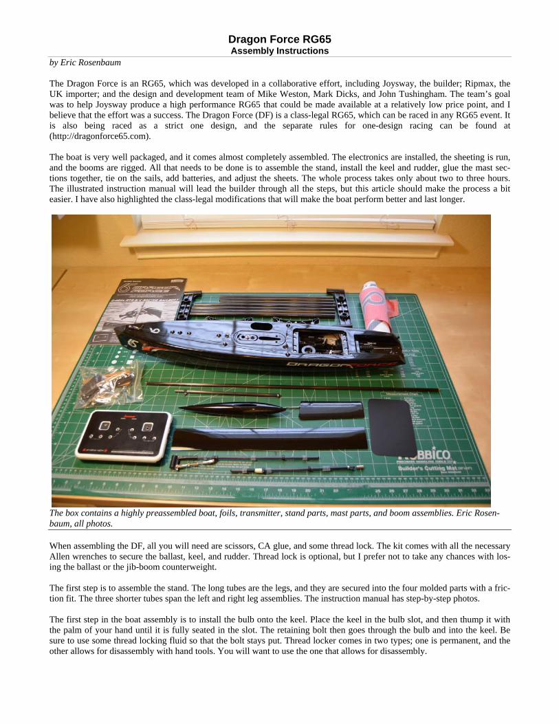
The mainsheet runs from the clip on the deck, through the ring on the mainsheet bridle, up through the forward boom eye band, and then through a bowsie on the way to the aft boom eye band, where it turns and goes back to the bowsie. Before you can accurately tie off the sheets, the radio must first be turned on, and the servos set to specific locations. What you want is to have the rudder servo centered and the sail servo sheeted in all the way. Once there, turn everything off again. If you will be using the supplied radio, just remember to always have the TX powered on before RX, and always turn the RX off before doing the same with the TX. If you do this, the receiver will not lose its bind to the radio. The kit comes with a 2.4 GHz transmitter, and the matching receiver is already installed and bound. The radio worked amaz-ingly well. It is very small and light. It lacks some of the features found on more expensive sets, but considering that it is in-cluded with the assembled boat, the value is pretty amazing. I read on an RC sailing forum that people were concerned about the range. This is not an issue. I had full control of the boat at a range of 550 feet, and that is much farther than you would ever sail a boat of this size. To set the mainsheet length, tie a loop in one end of the line and put on the clip where the elastic and mainsheet are joined. The sheet runs as described in the photo above, and the end is tied to the bowsie. The bowsie should be about half way be-tween the two boom-eye bands. The end of the boom should be pointed at a corner of the transom. Setting things up this way will allow for sufficient adjustment when sailing.
The loops on the ends of both sheets, along with the elastic attach on the clip as shown.
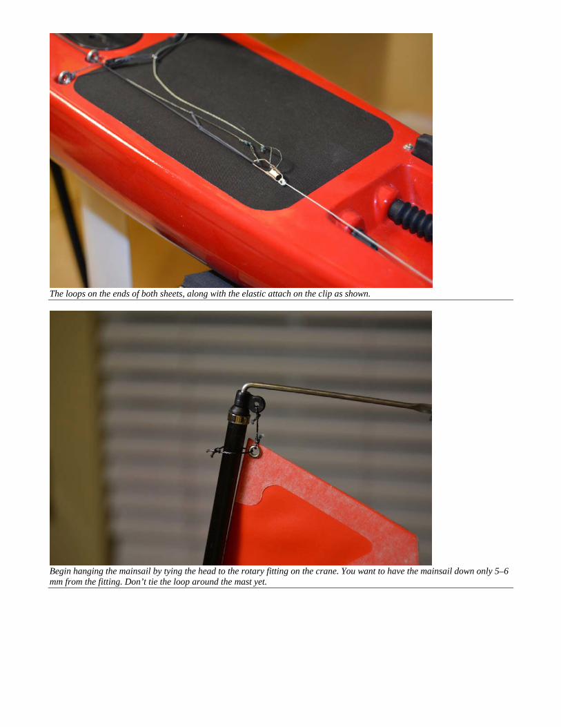
Begin hanging the mainsail by tying the head to the rotary fitting on the crane. You want to have the mainsail down only 5–6 mm from the fitting. Don’t tie the loop around the mast yet.

Next, tie the tack down by rigging a cunningham. The cunningham is a line that is tied to the top of the gooseneck as shown above. The line then loops up through the tack eyelet, then down through the hole at the bottom of the gooseneck, and then back to the silicone ring on the vang (see above). When the silicone ring is slid back, the line pulls down on the tack and tightens the mainsail’s luff. There will also be a loop that goes through the tack eyelet and around the mast. The procedure will be described later.
The clew is secured with a loop that goes around the boom and through the eyelet on the clew. Leave 2–3 mm clearance be-tween the sail and the boom fittings. Once tied in place, slide the silicone rings together. To adjust the curve of the sail’s foot, just move the silicone rings fore and aft.

The last step in tying on the mainsail is to put loops around the mast at the head, tack, and three intermediate tie points. You will want to tie the sails to the mast; don’t use the steel rings supplied with the kit. The rings will snag the topping lift when tacking, and that makes the boat almost impossible to sail. To get the correct amount of space between the sail and the mast, temporarily tape a section of 1/8" (3 mm) tube to the front of the mast. Tie the loop securely around both mast and tube, and then remove the small tube.
This is how the luff gap will look if the sail is tied on as discussed above. The small gap will allow the sail to easily tack back and forth, and the sail shape will be much better than if there was no gap. The jib and jib boom are next. The first step is to tie the jib to the jib boom. As was the case with the main boom, first posi-tion the silicone bands where indicated in the assembly manual. The forward boom eye band is glued in place, and the aft one is free to move.

The jib tack is tied to the eye on the fitting at the front of the jib boom. Leave enough slack in the loop so that the sail is about 2–3 mm above the fitting. The forestay is tied around the threaded rod that holds the counterweight.
The jib clew gets the same treatment as the mainsail clew.
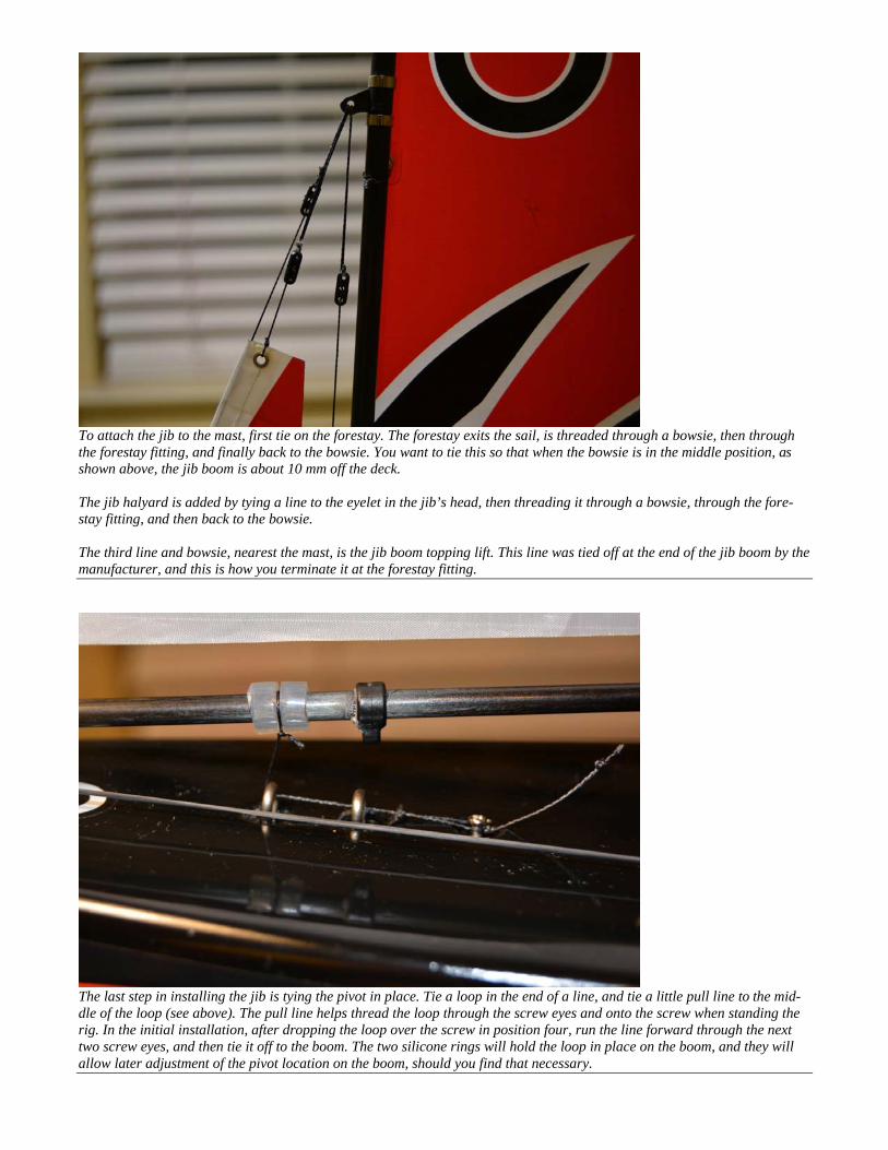
To attach the jib to the mast, first tie on the forestay. The forestay exits the sail, is threaded through a bowsie, then through the forestay fitting, and finally back to the bowsie. You want to tie this so that when the bowsie is in the middle position, as shown above, the jib boom is about 10 mm off the deck. The jib halyard is added by tying a line to the eyelet in the jib’s head, then threading it through a bowsie, through the fore-stay fitting, and then back to the bowsie. The third line and bowsie, nearest the mast, is the jib boom topping lift. This line was tied off at the end of the jib boom by the manufacturer, and this is how you terminate it at the forestay fitting.
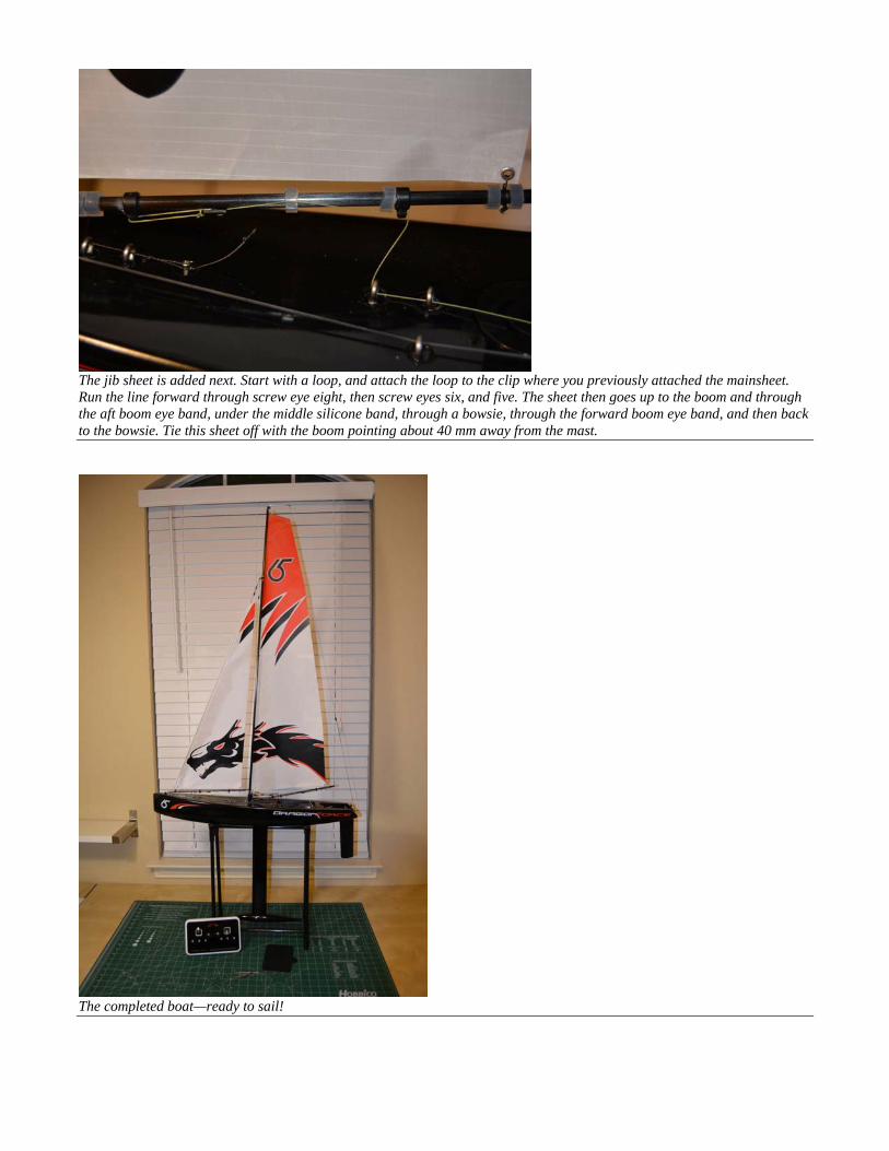
The last step in installing the jib is tying the pivot in place. Tie a loop in the end of a line, and tie a little pull line to the mid-dle of the loop (see above). The pull line helps thread the loop through the screw eyes and onto the screw when standing the rig. In the initial installation, after dropping the loop over the screw in position four, run the line forward through the next two screw eyes, and then tie it off to the boom. The two silicone rings will hold the loop in place on the boom, and they will allow later adjustment of the pivot location on the boom, should you find that necessary.
The jib sheet is added next. Start with a loop, and attach the loop to the clip where you previously attached the mainsheet. Run the line forward through screw eye eight, then screw eyes six, and five. The sheet then goes up to the boom and through the aft boom eye band, under the middle silicone band, through a bowsie, through the forward boom eye band, and then back to the bowsie. Tie this sheet off with the boom pointing about 40 mm away from the mast.
The completed boat—ready to sail!

There are a few other thoughts for you to consider. The first is whether you want to replace the battery with something a bit lighter. Many people have swapped out the four-AA holder and batteries for a 700 mAh LiFe battery. The smaller LiFe bat-tery is mounted to the keel box through the small starboard-side hole beside the mast. The battery is held in place with Vel-cro. Using a smaller and lighter battery helps the boat sit on its lines in the water, and you can change batteries by removing and replacing the small patch rather than the large main hatch. Just be sure that your new battery weighs at least 48 g, which is the minimum weight allowed in the rules. Speaking of deck hatches, the provided hatches are a bit small, and the adhesive is not aggressive enough for safety when the wind and waves build. Some people simply use electrical tape to hold these hatches in place, and that works fine. Others have swapped them out for sticky-backed Dacron, often called insignia cloth. The Dacron is pretty cheap and readily available from sail makers and kite parts suppliers. Dacron patches should not be reused. The supplied radio gear does not have end point adjustments as do many other radios, and you may find that there is not enough servo throw. If that is a problem with the sheets, then slide the forward boom eye band forward on the boom. This adjustment will allow for increased boom rotation. If the rudder throw is insufficient, then move the rudder pushrod attach-ment points on the servo arm and the rudder arm. If you move the pushrod out on the servo horn and in on the rudder horn, you will increase rudder throw quite dramatically. Don’t overdue a good thing. You do not want more than a 45-degree rota-tion from center. Even if you could get it, the boat would be more likely to stop than turn when you put the helm hard over. If you happen to have a boat with a wooden servo tray, you will want to seal the wood. Take the tray out of the boat, and ei-ther varnish it or apply a thin layer of epoxy to all surfaces and edges. You must waterproof the wood, or it will delaminate if it ever gets wet. I should mention that the modifications mentioned in this article are all class legal for both RG65s and the DF Restricted Class. If you wish to race your boat in a one-design DF fleet, be sure not to make any modification that is not allowed in the Restricted Class rules and the approved Hints & Tips page. Both of these documents can be found on the US RG65 Class website (www.RG65USA.org). Though a shorter keel is not approved in the Restricted Class, it is perfectly fine for any other RG65 Class event. If you sail in very “skinny” water, you might want to consider getting the shorter keel.
The long keel extends about 15" from the hull, while the shorter version is only about 9" below the hull. The boat sails fine with the shorter keel. In side-by-side comparisons, the shorter keeled boats heel more and tend to sideslip a bit more. How-ever, if the water is really shallow, you may not have a choice.