drafts in wide circulation - bureau of indian … · draft indian standard gf rp rock bolts...
TRANSCRIPT

Mining Techniques and Equipment Sectional Committee, MED 08
1) All Members of Mechanical Engineering Division Council
2) All Members of Mining Techniques and Equipment Sectional Committee, MED 08
3) All other interested members
Dear Sir (s),
Please find enclosed the following documents:
Doc No. Title
MED08(1477) Draft Indian Standard on GFRP rock bolts assemblies – Specification
Kindly examine the draft standards and forward your views, stating any difficulties which you are likely to
experience in your business or profession, if they are finally adopted as National Standards.
Last date for comments: 15 01 2017.
Comments, if any, may please be made in the format as given overleaf and mailed to the undersigned at
the above address.
In case no comments are received or comments received are of editorial nature, you will kindly permit us
to presume your approval for the above document as finalized. However, in case of comments of technical in nature
are received then it may be finalized either in consultation with the Chairman, Sectional Committee or referred to
the Sectional committee for further necessary action if so desired by the Chairman, Sectional Committee.
These documents are also hosted on BIS website [email protected].
Thanking you,
Yours faithfully
(A.Rangarajan)
. Scientist `E’ & Head MED
Room NO. 203, Manak Bhavan
9, Bahadur Shar Zafar Marg,
New Delhi -110002
Tele: 011-23232509(Extn. 4234)
Email: [email protected]
Encl.: As above
DRAFTS IN WIDE
CIRCULATION DOCUMENT DESPATCH ADVICE
Ref. Date
MED 08 /T- 92 02 12 2016

ा रिचालन द
नन नी ए ि व व व , ए डी8
_____________________________________________________________________________________
रव व : वि जीवन िीव ा रि द ी द नन नी ए ि व व व , ए डी8 ी द वचि न ाल वन ा
द ,
वननवलव ान द लन :
रल ा ी ष
ए डी8(1477) जीए ि ीि ट ली– व व वि
ा न द ा ल न ि ि नी व ा ा एए ज : द ान िाटरी ान र ाव जा न ि ल िन ा व ा ाि ाि ा राना ी
व ा जन व व वव15 01 7
व द ा ो ाीिी िवलव ि लन षट ल ा ल िद द व रा न ी व ा व ल ा ा ोीिटरटए ि रल वा व
द ाजा ा द व नी र व ए व व व ी िा ष व ा न ा ि ा ष ा ी वलएव व व जजान ादरल व द द ाजाए ा
रल ाि ी ान ि ा ट[email protected] ि ी लो
ो ाद, दी ,
ए. रगाराजन) शञा.` ई ’ एश रमॏख (एम.ई.डॎ)
कमरा या 3 म मानक नशन
9 बऻादॏरषाऻ जफर मागग नई दद लॎ टदलफोन: 011-23232509 (Extn. 4234)
Email: [email protected]
रन: िवलव
द ष ददना
ए डी08/टी–92 02 12 6
Doc: MED 08 (1477)c
Jan 2016
Draft Standard Draft For Comments Only
–
Draft Indian Standard GFRP ROCK BOLTS ASSEMBLIES - SPECIFICATION
Not to be reproduced without the permission of Last date for receipt of
BIS or used as a STANDARD comments is 15-01-2017
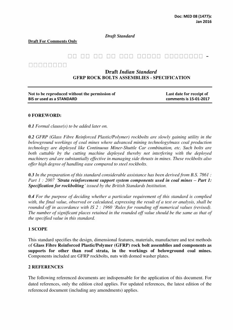
0 FOREWORD:
0.1 Formal clause(s) to be added later on.
0.2 GFRP (Glass Fibre Reinforced Plastic/Polymer) rockbolts are slowly gaining utility in the
belowground workings of coal mines where advanced mining technology/mass coal production
technology are deployed like Continuous Miner-Shuttle Car combination, etc. Such bolts are
both cuttable by the cutting machine deployed thereby not interfering with the deployed
machinery and are substantially effective in managing side thrusts in mines. These rockbolts also
offer high degree of handling ease compared to steel rockbolts.
0.3 In the preparation of this standard considerable assistance has been derived from B.S. 7861 :
Part 1 : 2007 ‘Strata reinforcement support system components used in coal mines – Part 1:
Specification for rockbolting’ issued by the British Standards Institution.
0.4 For the purpose of deciding whether a particular requirement of this standard is complied
with, the final value, observed or calculated, expressing the result of a test or analysis, shall be
rounded off in accordance with IS 2 : 1960 ‘Rules for rounding off numerical values (revised). The number of significant places retained in the rounded off value should be the same as that of
the specified value in this standard.
1 SCOPE
This standard specifies the design, dimensional features, materials, manufacture and test methods
of Glass Fibre Reinforced Plastic/Polymer (GFRP) rock bolt assemblies and components as
supports for other than roof strata, in the workings of belowground coal mines.
Components included are GFRP rockbolts, nuts with domed washer plates.
2 REFERENCES
The following referenced documents are indispensable for the application of this document. For
dated references, only the edition cited applies. For updated references, the latest edition of the
referenced document (including any amendments) applies.

Doc: MED 08 (1477)c
Jan 2016
2.1 IS 13360 : Part 5 : Sec 1 1996 Plastics - Methods of Testing Part 5 : Mechanical Properties
Sec 1 Determination of Tensile Properties - General Principles
2.2 BS EN 13463-1, non-electrical equipment for potentially explosive atmospheres – Part 1:
Basic method and requirements
2.3 IS 1363 : Part 3 2002 Hexagon Head Bolts, Screws and Nuts of Product Grade C - Part 3 :
Hexagon Nuts (Size Range M5 to M64)
3 TERMINOLOGY
3.0 For the purpose of this standard, the following definitions shall apply.
3.1 Bond strength- load in a rockbolt/resin/rock system at which the system stiffness falls below
20 kN/mm, when measured by pull testing, for a given bond length.
3.2 Domed washer plate- accessory which, when used in conjunction with a rockbolt, nut,
facilitates load distribution, ensures correct alignment and reduces weathering around the mouth
of the rockbolt hole.
3.3 Equivalent diameter- diameter of an equivalent circular bar calculated from the weight and
density of a 150 mm long sample of actual bar.
3.4 Flexural strength- maximum flexural stress occurring at the surfaces of the test specimen
during a bending test, based on the maximum load sustained during the test and assuming that
the neutral axis is through the middle of the section.
.
3.5 Rockbolt- bar inserted into the roof or side of a roadway, used with fully encapsulating resin
as part of a rockbolting support system.
3.6 Rockbolt assembly- rockbolt complete with appropriate end fittings. An example of rockbolt
assembly is given in Figure 1.
3.7 System stiffness- stiffness of the rockbolt/resin/rock system for a given bond length in load
per unit displacement (kN/mm), when measured by pull testing.
4 MATERIAL, DESIGNS AND MANUFACTURE
4.1 General
4.1.1 Glass Fibre Reinforced Plastic (GFRP) rockbolt assemblies and components shall not be
used for supporting roof strata in the below ground workings of coal mines. The complete
assembly of GFRP rockbolt assembly consisting of the GFRP rockbolt, nut with domed washer
plate shall be manufactured by one single manufacturer having all necessary arrangements and
facilities thereof. Every GFRP rockbolt and the nut with domed washer supplied along with shall
be suitably marked by the manufacturer.
4.2 Rockbolt bar

Doc: MED 08 (1477)c
Jan 2016
GFRP rockbolts and components are meant for use in the side rock stabilisation.
4.2.1 Material composition
The bar of the GFRP rockbolt shall be made from a polymer resin matrix with a maximum glass
content of 75% by weight.
Figure 1: GFRP Rockbolt Assembly
4.2.2 Profile Design and Manufacture
The bar of the GFRP rockbolt shall be of circular section and may have a rough or threaded
surface.
The minimum equivalent diameter of the GFRP rockbolt bar shall be not less than 21.5 mm. The
minimum measurement across the thread root diameter shall be not less than 20 mm.
Straightness shall be within 0.5% of the length of the GFRP rockbolt bar.
Proximal end the minimum length of the thread of the GFRP rockbolt bar shall be 150 mm. The
thread shall be compatible with the nut. The distal end the GFRP rockbolt bar shall be machined
and free from burrs or edges which protrude beyond the profile of the rockbolt.
The tolerance on the manufactured length of the GFRP rockbolt bar shall be ± 5 mm.
4.3 Nut with domed washer plate
Domed washer plate when used in conjunction with a rockbolt nut, facilitates load
distribution, ensures correct alignment and reduces weathering around the mouth of the rockbolt
hole. An example of Nut with domed washer is given in Figure 2. Nut with domed washer
should be compatible to rockbolt thread and diameter of washer plate shall be 150mm.

Doc: MED 08 (1477)c
Jan 2016
4.3.1 Material composition
The nut with domed washer for the GFRP rockbolt shall be made from a polymer resin matrix
with a maximum glass content of 75% by weight and its thickness shall be not less than 30 mm.
The nut shall be compatible with the bar thread and conform to 7.1.
Figure 2. Nut with domed washer plate
4.3.2 Material properties
4.3.2.1 Electrical resistance
The antistatic properties of the GFRP rockbolt bar shall be in accordance with BS EN 13463-1.
4.3.2.2 Fire resistance of domed washer plate
When the domed washer plate is tested in accordance with Annexure I, the persistence of flame
time shall be less than 10 s.
5 TESTS
5.1 Tensile strength
5.1.1 When tested in accordance with Annexure II the GFRP rockbolt bar shall have a tensile
strength of not less than 850 N/mm2.
5.1.2 When tested in accordance with double embedment pull test as given in Annexure IIA
shall provide maximum load attainable by the resin embedded GFRP rockbolt. Maximum load
attainable shall not be less than 320 kN.
5.2 Flexural strength

Doc: MED 08 (1477)c
Jan 2016
When tested in accordance with Annexure III the material shall have a flexural strength of not
less than 750 N/mm2 based on the maximum load recorded during the test.
5.3 Tensile test of threads
When tested in accordance with Annexure IV the threaded portion of the rockbolt, or the thread
of the assembly nut, shall not fail at a load less than 60 kN and shall not fail in a sudden manner.
5.4 Shear test
When tested in accordance with Annexure V the shear strength of the rockbolt /resin system
shall be at least 260 N/mm2.
5.5 Bond strength and system stiffness
When tested in accordance with Annexure VI the minimum system bond strength shall be 120
kN and the minimum system stiffness shall be 100 kN/mm measured between loads of 40 kN
and 80 kN.
6. SAMPLING
(Sampling requirements to be provided by DGMS/Members of MED 08)
7. MARKING
7.1 The nut with domed washer supplied with the GFRP rockbolt shall be marked to identify the
supplier.The rockbolt assembly shall have the following information marked in a permanent and
legible manner in a location, where it is accessible and visible:
a) Name and address of manufacturer;
b) Type or serial number;
c) Month and year of manufacture;
7.2 BIS Certification Marking
Each rockbolt assembly may also be marked with the Standard Mark.
7.2.1 The use of the Standard Mark is governed by the provisions of Bureau of Indian Standards
Act, 1986 and the Rules and Regulations made there under. The details of conditions under
which a license for the use of Standard Mark may be granted to the manufacturers or the
producers may be obtained from the Bureau of Indian Standards.

Doc: MED 08 (1477)c
Jan 2016
Annexure 1
FIRE RESISTANCE TEST ON NON-METALLIC COMPONENTS
(Clause 4.2.1 & 4.3.2)
0 Principle
The persistence of flame is determined by subjecting test pieces of a given size to a naked flame
for a specified time.
1 Apparatus
1.1 Draught-free flame test cabinet, as shown in Figure 3, consisting of a box with:
• a dark interior; • a hole in the top to allow the escape of fumes; • a sliding door with a viewing panel of acrylic or other suitable material;
• a suitable stand for supporting the test piece inside the cabinet, the side of which is provided with a hand hole and a flap to permit handling of the burner (see F.3.2).
1.2 Barthel burner, as the source of ignition.
2 Procedure
2.1 Sample size
Test six 300 mm lengths of rockbolt bar. Test six samples of domed washer plate.
2.2 Method
Prior to the test adjust the flame in subdued lighting conditions to a height of 150 mm with the
burner standing vertically. Mount the burner at an angle 45° to the horizontal with the top burner
50 mm from the
specimen under test such that the flame impinges at an angle of 90° to the test specimen’s longitudinal axis.
Allow the flame to impinge on the specimen for 60 s and then withdraw.
3 Results
After withdrawing the flame measure the persistence time of any visible flame or glow on the
test piece.
Calculate the mean of the persistence times determined for the six specimens.

Doc: MED 08 (1477)c
Jan 2016
Figure 3 Draught-free flame test cabinet, as shown in

Doc: MED 08 (1477)c
Jan 2016
Annexure II
TENSILE STRENGTH TEST ON GFRP BAR (Clause 5.1.1)
0 Principle
The tensile strength of GFRP bar is determined by subjecting the test sample to a tensile force
until failure occurs.
1 Apparatus
1.1 Testing machine of a type with a constant rate of crosshead movement and comprising the
following.
• A fixed stationary member carrying one grip. • A moveable member carrying a second grip. • An autographic recording facility or other means of producing a load/extension graph.
1.2 Self-aligning wedge type grips, for holding the test specimen between the fixed member and
the moveable member of the testing machine in such a manner that they will move freely into
alignment as soon as the load is applied without any slippage relative to the grips.
2 Test specimens
Test five specimens with the dimensions shown in Figure 4
3 Procedure
3.1 Measure and record the diameter of the machined portion of the specimen under test to the
nearest 0.01 mm at a minimum of two points along their length.
3.2 Ensure that the teeth of the wedge grips are clean and free of debris before inserting the test
specimen.
3.3 Place the specimen in the testing machine, taking care that it is aligned with both top and
bottom wedge grips. The distances between the ends of the gripping surfaces are shown in
Figure-4. Tighten the grips evenly and firmly to the degree necessary to prevent slippage of the
specimen during the test, but not to the point where the specimen would be crushed.
3.4 Apply a force at a rate of 5mm/min until failure.
3.5 Record the load extension curve of the specimen under test and the maximum force achieved.
4 Results
Calculate the tensile strength for each specimen by dividing the maximum load in newtons by
the original minimum cross-sectional area of the machined portion in mm2. All specimens are
required to pass the tensile strength of 850 N/mm2.

Doc: MED 08 (1477)c
Jan 2016

Doc: MED 08 (1477)c
Jan 2016
Figure 4 Arrangement for tensile test on GFRP bar

Doc: MED 08 (1477)c
Jan 2016
Annexure IIA
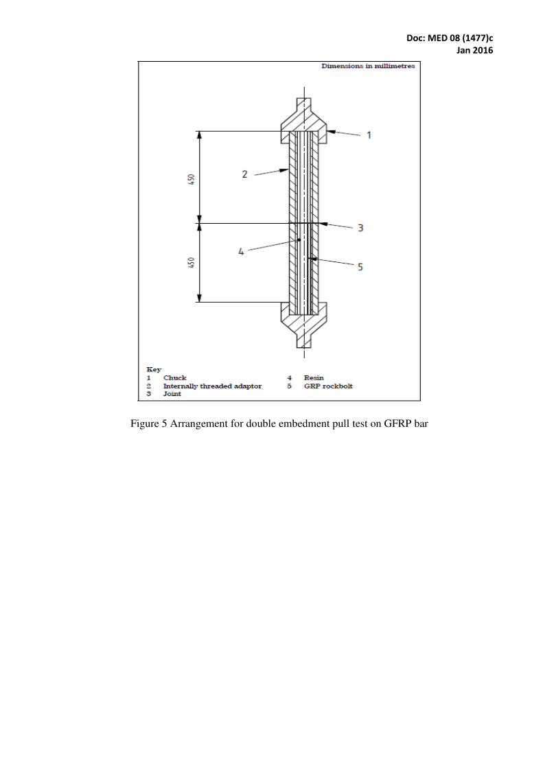
DOUBLE EMBEDMENT PULL TEST ON GFRP BAR (Clause 5.1.2)
0 Principle
The maximum load achievable, when a GFRP bar is encapsulated in two 450 mm long steel
tubes, is determined from a double embedment pull test. The test consists of tensile loading a
jointed tube assembly in which a sample of GFRP bar has been embedded using high-strength
slow-set polyester resin.
1 Apparatus
1.1 Testing apparatus, comprising:
a) a suitably calibrated test rig which permits application of load at a steady rate and in an
axial direction relative to the tube assembly.
b) a tensile testing machine, having a suitable recording facility
1.2 Instrumentation device, suitably calibrated, for measuring the load.
1.3 Sample tubes, consisting of two thick walled tubes (at least 10 mm), each:
• 450 mm long; • with a minimum internal diameter equal to the maximum diameter of the GFRP bar plus 5
mm;
• with a 1 mm deep by 2 mm pitch thread machined into the surface of the bore to provide a standard surface finish and inhibit failure between this surface and the resin; and
• designed with the test rig to ensure uniaxial loading.
2. Procedure
2.1 Sample preparation
Prepare three test assemblies such that a 900 mm long sample of the GFRP bar is centrally
located within the two 450 mm steel sample tubes butted together and fully encapsulated by
hand-mixed, high-strength, polyester resin (see Figure 5). When pushing the GFRP bar through
the resin, rotate it slowly to ensure centralization. Prepare the resin according to the
manufacturer’s instructions, ensuring that the assembly is completed within the resin gel time. Ensure that the finished assembly is straight and that the GFRP bar and embedment tubes are
axially aligned.
2.2 Testing
Test each of the three sample test assemblies not less than 24 h after their preparation.
Locate each assembly in the testing machine or test rig. Set the recording system to record load
at a suitable rate. Apply load in a controlled manner at a rate of approximately 3 kN/s until such
time as the maximum load is achieved.
2.3 Results
The minimum tensile strength of the GFRP bar is the lowest maximum load from the three tests.
Doc: MED 08 (1477)c
Jan 2016
Figure 5 Arrangement for double embedment pull test on GFRP bar
Doc: MED 08 (1477)c
Jan 2016
Annexure III
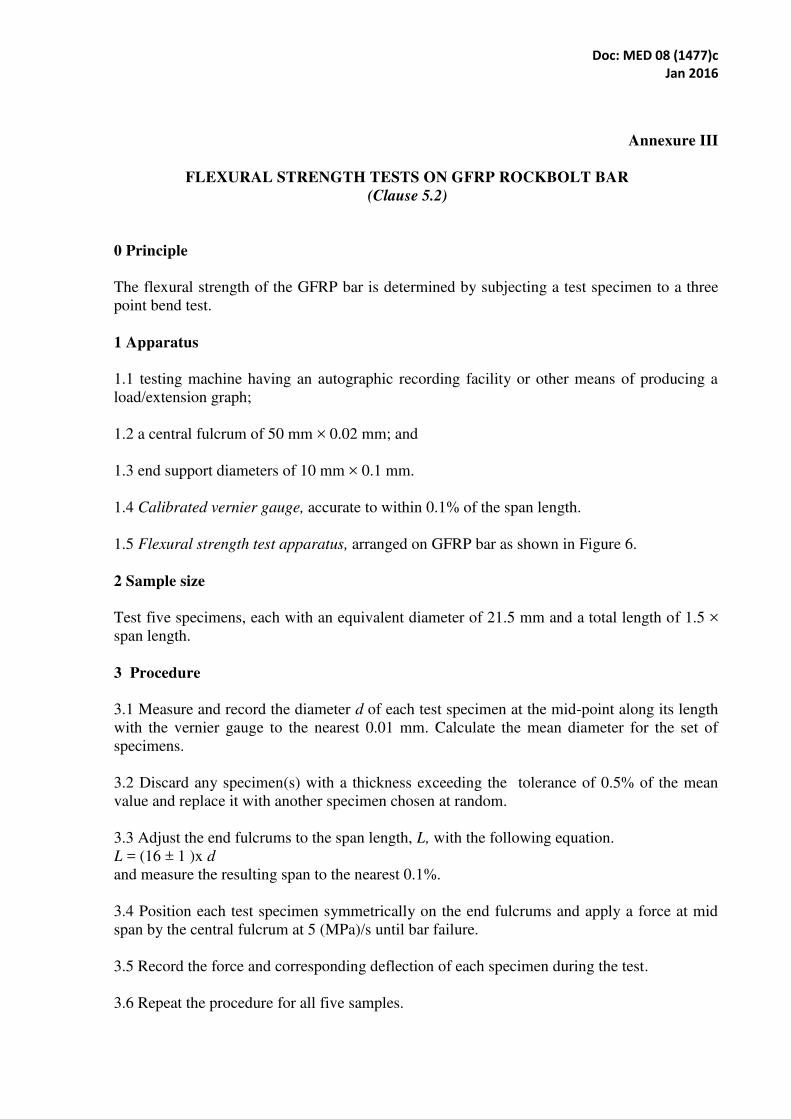
FLEXURAL STRENGTH TESTS ON GFRP ROCKBOLT BAR
(Clause 5.2)
0 Principle
The flexural strength of the GFRP bar is determined by subjecting a test specimen to a three
point bend test.
1 Apparatus
1.1 testing machine having an autographic recording facility or other means of producing a
load/extension graph;
1.2 a central fulcrum of 50 mm × 0.02 mm; and
1.3 end support diameters of 10 mm × 0.1 mm.
1.4 Calibrated vernier gauge, accurate to within 0.1% of the span length.
1.5 Flexural strength test apparatus, arranged on GFRP bar as shown in Figure 6.
2 Sample size
Test five specimens, each with an equivalent diameter of 21.5 mm and a total length of 1.5 ×
span length.
3 Procedure
3.1 Measure and record the diameter d of each test specimen at the mid-point along its length
with the vernier gauge to the nearest 0.01 mm. Calculate the mean diameter for the set of
specimens.
3.2 Discard any specimen(s) with a thickness exceeding the tolerance of 0.5% of the mean
value and replace it with another specimen chosen at random.
3.3 Adjust the end fulcrums to the span length, L, with the following equation.
L = (16 ± 1 )x d
and measure the resulting span to the nearest 0.1%.
3.4 Position each test specimen symmetrically on the end fulcrums and apply a force at mid
span by the central fulcrum at 5 (MPa)/s until bar failure.
3.5 Record the force and corresponding deflection of each specimen during the test.
3.6 Repeat the procedure for all five samples.
Doc: MED 08 (1477)c
Jan 2016
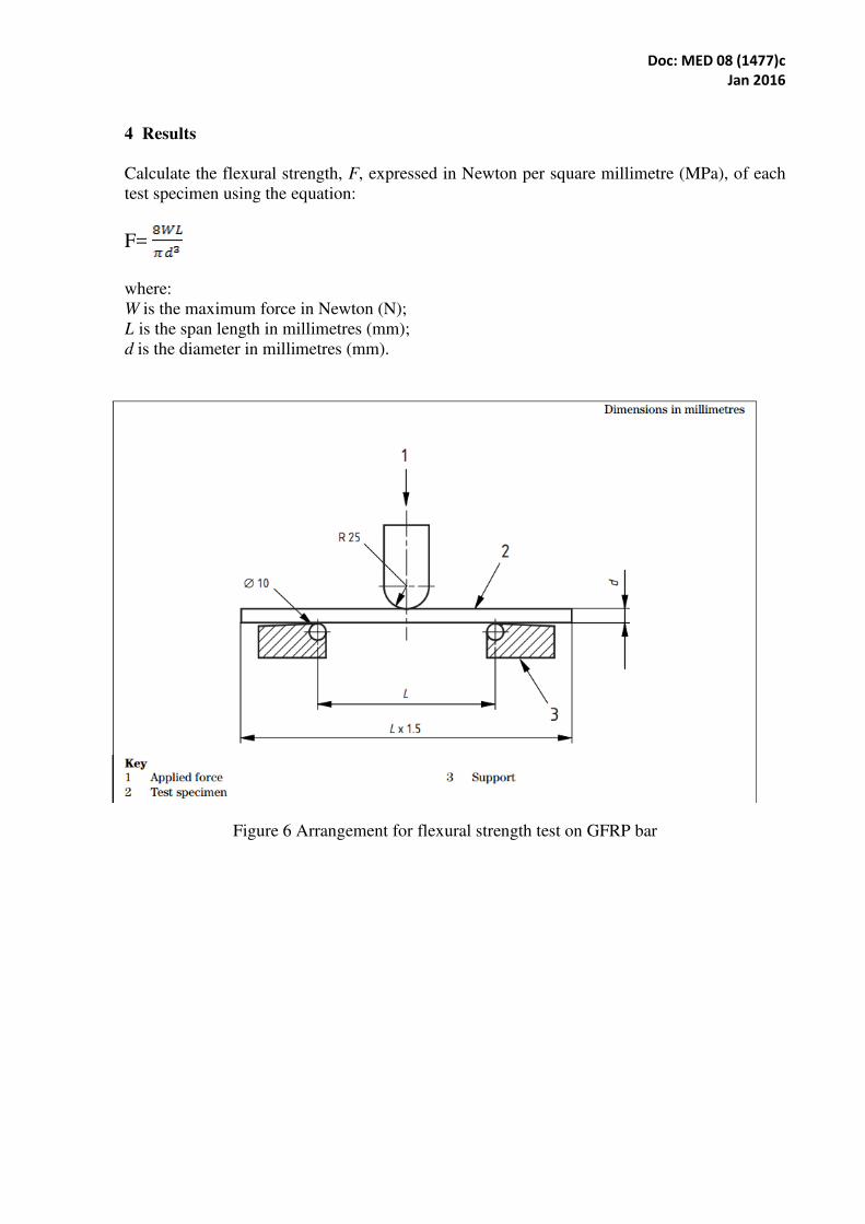
4 Results
Calculate the flexural strength, F, expressed in Newton per square millimetre (MPa), of each
test specimen using the equation:
F=
where:
W is the maximum force in Newton (N);
L is the span length in millimetres (mm);
d is the diameter in millimetres (mm).
Figure 6 Arrangement for flexural strength test on GFRP bar

Doc: MED 08 (1477)c
Jan 2016
Annexure IV
TENSILE TEST ON ROCKBOLT THREADED END
(Clause 5.3)
0 Principle
The tensile strength of the rockbolt threaded end is determined by subjecting the rockbolt and nut
assembly to a tensile force until failure occurs.
1 Apparatus
1.1 Tensile test machine, having an autographic recording facility or other means of producing a
load/extension graph.
Figure 6.Rockbolt assembly arrangement for thread test
2 Procedure
2.1 Sample size
Test a minimum of three specimens.
2.2 Loading
Place each test assembly in the tensile test machine and apply load at a stress rate not exceeding
10 (MPa)/s until failure occurs.
3 Results
For each specimen, record the maximum load at the point of failure and note the mode of failure.
The failure load is the lowest maximum from all of the specimen tests.

Doc: MED 08 (1477)c
Jan 2016
Annexure V
SHEAR TEST ON ROCKBOLT/RESIN SYSTEM
(Clause 5.4)
0 Principle
The ultimate shear strength of a rockbolt/resin system is determined using a single shear frame in
conjunction with a rockbolt/resin double embedment assembly.
1 Apparatus
1.1 Single (guillotine) shear frame, as shown in Figure 7 suitable for the testing of a
rockbolt/resin assembly.
1.2 Tensile test machine, having an autographic recording facility or other means of producing a
force/displacement graph.
1.3 Three test assemblies, consisting of two thick-walled hollow steel tubes, each tube having:
• A length of 125 mm, an internal diameter 5 mm greater than the nominal rockbolt
diameter and a wall thickness of at least half the rockbolt diameter; and
• A 1 mm deep by 2 mm pitch metric thread machined onto its internal surface in order to
provide a standard surface finish and thereby inhibit failure between this surface and the
resin. The arrangement of the test assembly is shown in Figure 7.
1.4 Displacement transducer, used to record accurately the separation of the two tubes.
Figure 7 Shear test assembly

Doc: MED 08 (1477)c
Jan 2016
Annexure VI
DETERMINATION OF BOND STRENGTH AND SYSTEM STIFFNESS
(Clause 5.5)
0 Principle
The bond strength and system stiffness are determined from a laboratory short encapsulation pull
test. A rockbolt sample is installed in a confined rock core, using capsule resin, and, after resin
curing, is pull-tested under controlled conditions. Bond performance is assessed in terms of the
bond displacement measured against the applied load.
1 Apparatus
1.1 Testing apparatus, comprising a machine tool lathe, such as that shown in Figure 8, a
hydraulic biaxial cell, a water feed system and drill assembly.
1.2 Pull test equipment:
Comprising a hydraulic hollow ram jack, a pressure bearing plate or stressing stool, a hydraulic
hose, a pressure gauge and/or load cell with a calibration error no greater than that of the
pressure gauge, and a hydraulic pump fitted with a non-return valve, as shown
in Figure 9; and
NOTE The hydraulic cylinder has to have an effective area within 0.2% of the nominal value
provided by the manufacturer.
Capable of applying a load at least equivalent to 90% of the yield strength of the rock bolt under
test.
1.3 Autographical recording facility or other means of producing a load/extension graph for
recording the test data during pull testing, as shown in Figure 9. Linear variable differential
transducer (LVDT) or dial gauge may be used to record bolt, end displacement and an in-line
pressure gauge, preferably with an electronic transponder and/or suitable capacity load cell, to
record the applied load/pressure.
1.4 Machine tool lathe:
• having sufficient bed length to allow the drilling operations to be carried out in a single pass;
• capable of a throw of 190 mm or more and a rotation speed of 440 rpm;
• offering a minimum torque of 200 Nm; and
• preferably having an automated feed rate of 1.25 mm/rev.
1.5 Biaxial cell, having a nominal internal diameter of at least 145 mm and a minimum confining
membrane length of 200 mm, capable of applying a confining pressure of at least 10 MPa. A
hydraulic biaxial pressure cell is shown in Figure 10.

Doc: MED 08 (1477)c
Jan 2016
Figure 8: General arrangement of lathe based pull test apparatus
1.6 Water feed, allowing flushing water to be delivered effectively through a rotating drill rod,
fixed in the chuck of the lathe to the tip of the drill bit during drilling operations.
1.7 Drilling consumables, preferably with a twin wing, negative rake, carbide-tipped drill bit, to
produce an average finished hole diameter of (6.5 ± 0.5) mm greater than the equivalent bolt
diameter.
1.8 Rock test specimens, consisting of sandstone rock cores, each:
• with a minimum length of 220 mm and an external diameter to match the internal diameter of the biaxial cell used;
• comprising poorly cemented, medium grained, homogeneous sandstone with rounded, well-
sorted grains;
• meeting the performance criteria specified in 4; and
• when tested according to ISRM Suggested Methods1), having uniaxial compressive strength of between 21 and 31 MPa and a Young’s Modulus of between 7 and 10
4 MPa1).

Doc: MED 08 (1477)c
Jan 2016
Figure 9 General arrangement of hydraulic pull test apparatus
Fig. 10 Hydraulic biaxial pressure cell

Doc: MED 08 (1477)c
Jan 2016
2 Procedure
2.1 Rock core preparation
Do not use core specimens with major irregularities, bedding or discontinuities. Remove or fill
with a suitable self-hardening filler compound any minor irregularities or depressions found in
the outer surface of the rock core to avoid localized deformation of the cell membrane under
pressure.
2.2 Installing rock core in biaxial cell
Place the rock core inside the biaxial cell, ensuring that the cell membrane has full
circumferential and axial contact with the rock core. Do not permit more than 10 mm of rock
core to protrude from one end of the cell. Apply a confining pressure of 10 MPa to the rock core
using the biaxial cell, and maintain this throughout testing. Securely mount the biaxial cell on the
lathe stock such that the axis of the rock core is in alignment with the axis of the lathe chuck and
the end, with no more than 10mm of core protruding from the biaxial cell, faces the lathe chuck.
2.3 Drilling
Use only sharp undamaged drill bits of the correct type and dimensions and correct specification
drill rods in good condition that are clear of debris and have full flushing functionality. Mark the
drill rod 160 mm from the bit end. Mount the drill rod in the lathe chuck such that it is
concentric, not more than the required length of drill rod extends beyond the face of the chuck
and the water feed is attached. Advance the lathe stock until the face of the rock core is close to
the drill bit. Operate the lathe at the correct rotation speed (approximately 440 rpm), apply
flushing water, then manually advance the lathe stock to initiate drilling. Once the drill bit has
begun to penetrate the rock core, ensure that rock penetration continues at the appropriate rate
(approximately 1.25 mm/rev).When the rock core has been drilled to the correct depth (160 mm),
withdraw the stock slowly, maintaining lathe rotation and flushing water pressure. Ensure the
hole is free of debris and is 160 mm long.
2.4 Bolt installation
Measure and record the internal diameter of the drilled hole using a calibrated borehole
micrometer, recording the diameter for at least four positions evenly distributed along the length
of the borehole. From these readings determine the average borehole diameter, checking that the
average diameter is 6.5mm ± 0.5mm greater than the equivalent rock bolt diameter.
Ensure the rockbolt to be tested is clean and free from contaminants, and is long enough to allow
assembly of pull testing equipment after bolt installation (see Figure 9). Cut the end of the bolt to
be inserted into the rock core normal to the axis of the bolt. Remove the confined rock core from
the lathe and place it upright on a bench. Fill the borehole with slow set-resin, which has been
pre-mixed according to the manufacturer’s instructions, ensuring that the catalyst has been fully dispersed. Push the rockbolt to be tested into the borehole by hand, ensuring as far as possible
that the bar is central and fully to the back of the hole. Leave the assembly for at least one hour
and pull-test within 2 hours of mixing.
2.5 Pull testing

Doc: MED 08 (1477)c
Jan 2016
Assemble pull test equipment on the installed bolt and core in the lathe as shown in Figure 8.
Operate the hydraulic pump at 1 kN/s, applying increasing pressure to the hydraulic jack. Record
the bolt end displacement at regular load intervals. Cease pump operation either when the bolt
end displacement exceeds 10 mm in total or at 90% of the load at which the yield strength of the
rockbolt would be reached.
After pull testing, relieve the pressure from the pull test jack before relieving the pressure from
the biaxial cell to prevent tensile failure of the rock core.
2.6 Core examination
After testing, withdraw the rock core from the biaxial cell and split the core in the axial plane in
order to inspect the quality of installation and mode of bond failure. Examine both the resin/bolt
and the resin/rock interfaces and note the location of any shear failure.
3 Results
Prepare a load/extension graph for applied load against bond displacement where:
Bond displacement (mm) equals measured displacement minus extension in bolt free length (see
Equation 1)
The extension in bolt free length, X, expressed in millimetres (mm), is given by the equation:
X=
where:
F is the applied force in Newton (N);
L is the bolt free length in millimetres (mm);
E is the Young’s Modulus of the bolt material in MPa; d is the nominal bolt diameter in millimetres (mm).
Determine the system stiffness and the bond strength, i.e. the applied force at which the slope of
the graph falls below 20 kN/mm, from the mean of the best three results of five tests.
4 Rock core performance criteria
When tested in accordance with the procedure described in 3and using the standard consumables
and criteria listed in Table 1, the rock core shall provide test results which lie within the
performance envelope shown in Figure 11. Bond failure shall be at the rock/resin interface.
Standard consumables and criteria for rock core performance testing
Hole diameter 28.5 mm ± 0.5 mm
Bond length 160 mm
Confining pressure (biaxial cell) 10 MPa
Drill rod type 19 mm A/F, hollow, hexagonal
Bar type M24 high tensile continuously threaded steel
bar, grade 10.9 steel (yield strength 312 kN,
UTS 346 kN)
Resin Conforming to Clause 6

Doc: MED 08 (1477)c
Jan 2016
Figure 11 Rock core performance envelope