draft tube calculations using openfoam-1.5dev and
TRANSCRIPT
1
Draft Tube calculations using OpenFOAM-1.5dev and validation with FLINDT data
C. Devals, Y. Zhang and F.GuibaultÉcole Polytechnique de Montréal, Canada
T. Vu and B. NennemannAndritz Hydro, Pointe-Claire, Canada
6th OpenFOAM Workshop, June 13-16 2011, PennState University, USA
2
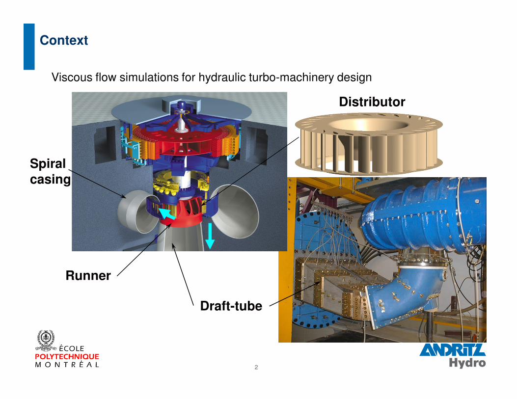
Viscous flow simulations for hydraulic turbo-machinery design
Runner
Draft-tube
Spiral
casing
Context
Distributor
3
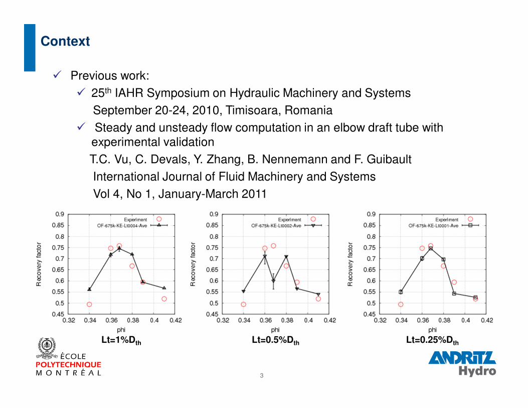
� Previous work:� 25th IAHR Symposium on Hydraulic Machinery and Systems
September 20-24, 2010, Timisoara, Romania� Steady and unsteady flow computation in an elbow draft tube with
experimental validationT.C. Vu, C. Devals, Y. Zhang, B. Nennemann and F. GuibaultInternational Journal of Fluid Machinery and SystemsVol 4, No 1, January-March 2011
Context
Lt=0.5%DthLt=1%Dth Lt=0.25%Dth
4
� Understand why the recovery coefficient for Phi=0.368 shows an important decrease for Lt=0.5%Dth.
� Validate OpenFOAM RANS simulations for draft tube on hexahedral meshes
� Compare recovery coefficient χ prediction with experimental data
Objectives
5
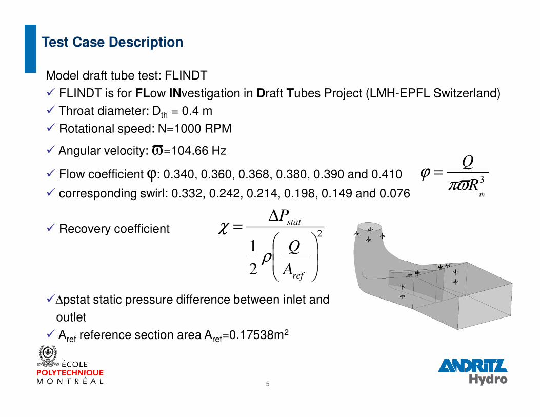
Model draft tube test: FLINDT� FLINDT is for FLow INvestigation in Draft Tubes Project (LMH-EPFL Switzerland)� Throat diameter: Dth = 0.4 m� Rotational speed: N=1000 RPM
� Angular velocity: ϖ=104.66 Hz
� Flow coefficient ϕ: 0.340, 0.360, 0.368, 0.380, 0.390 and 0.410
� corresponding swirl: 0.332, 0.242, 0.214, 0.198, 0.149 and 0.076
� Recovery coefficient
�∆pstat static pressure difference between inlet and outlet
� Aref reference section area Aref=0.17538m2
Test Case Description
3
thR
Q
πϖϕ =
2
2
1
∆=
ref
stat
A
Q
P
ρ
χ
6
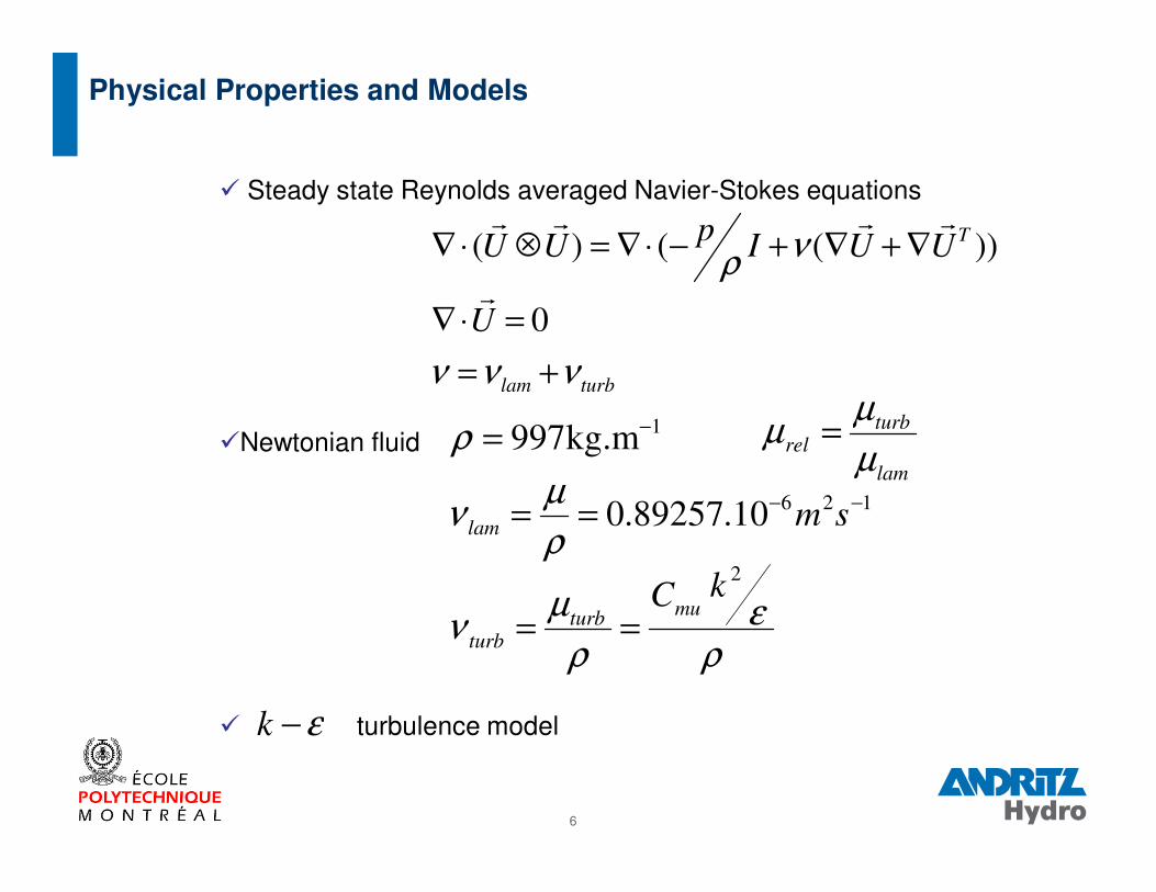
� Steady state Reynolds averaged Navier-Stokes equations
�Newtonian fluid
� turbulence model
126
1
10.89257.0
kg.m997
−−
−
==
=
smlamρ
µν
ρ
ε−k
turblam
T
U
UUIp
UU
ννν
νρ
+=
=⋅∇
∇+∇+−⋅∇=⊗⋅∇
0
))(()(
r
rrrr
Physical Properties and Models
ρε
ρ
µν
2kCmu
turbturb ==
lam
turbrel
µ
µµ =
7
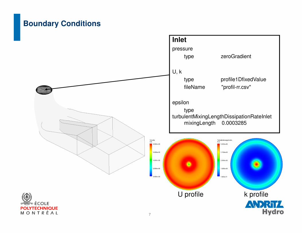
Boundary Conditions
Inlet
pressure
type zeroGradient
U, k
type profile1DfixedValue
fileName "profil-rr.csv"
epsilon
type turbulentMixingLengthDissipationRateInlet
mixingLength 0.0003285
U profile k profile
8
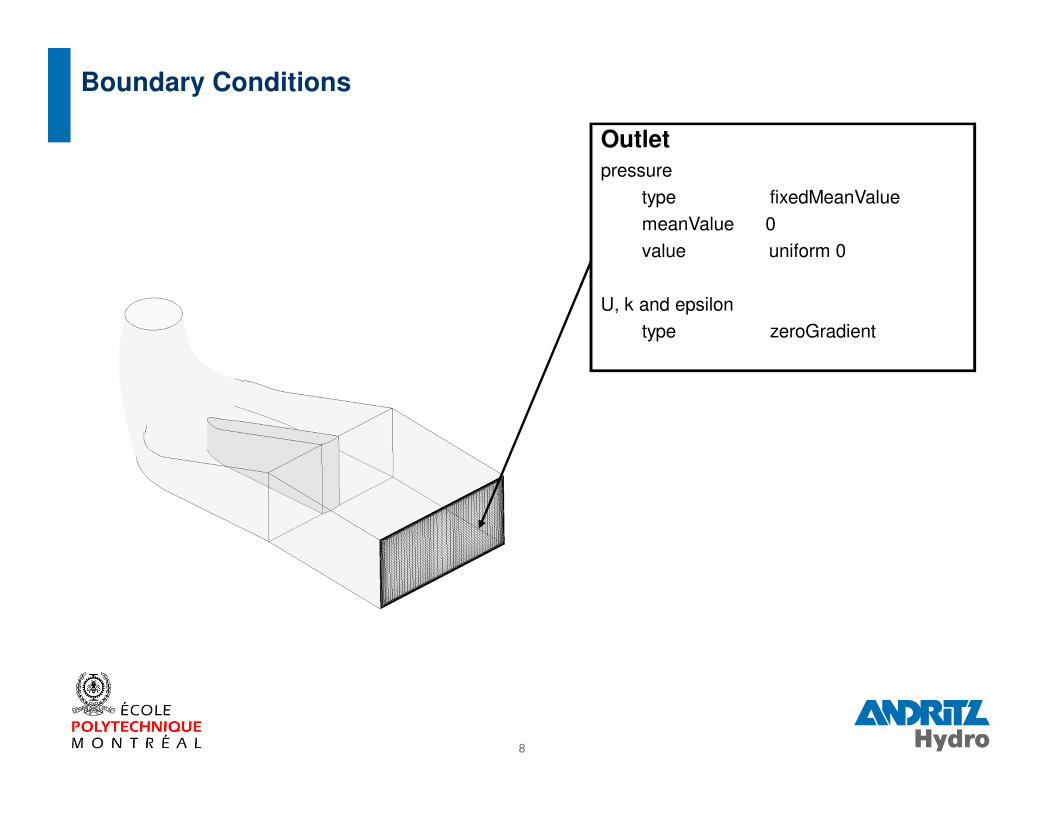
Boundary Conditions
Outlet
pressure
type fixedMeanValue
meanValue 0
value uniform 0
U, k and epsilon
type zeroGradient
9
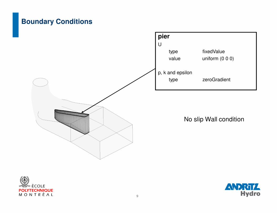
Boundary Conditions
pier
U
type fixedValue
value uniform (0 0 0)
p, k and epsilon
type zeroGradient
No slip Wall condition
10
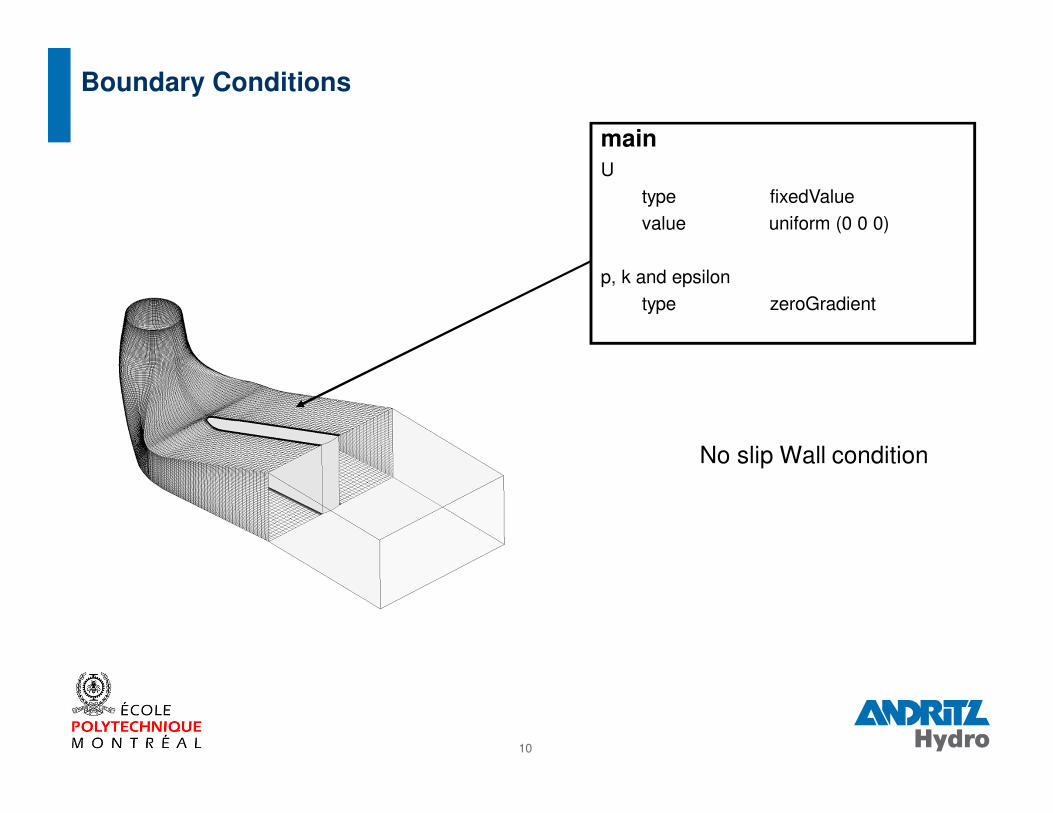
Boundary Conditions
main
U
type fixedValue
value uniform (0 0 0)
p, k and epsilon
type zeroGradient
No slip Wall condition
11
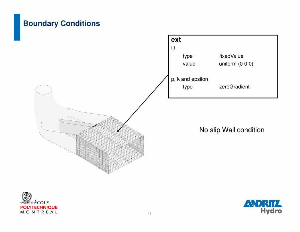
Boundary Conditions
ext
U
type fixedValue
value uniform (0 0 0)
p, k and epsilon
type zeroGradient
No slip Wall condition
12
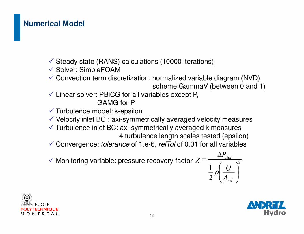
� Steady state (RANS) calculations (10000 iterations)� Solver: SimpleFOAM� Convection term discretization: normalized variable diagram (NVD)
scheme GammaV (between 0 and 1)� Linear solver: PBiCG for all variables except P,
GAMG for P� Turbulence model: k-epsilon� Velocity inlet BC : axi-symmetrically averaged velocity measures� Turbulence inlet BC: axi-symmetrically averaged k measures
4 turbulence length scales tested (epsilon)� Convergence: tolerance of 1.e-6, relTol of 0.01 for all variables
� Monitoring variable: pressure recovery factor
Numerical Model
2
2
1
∆=
ref
stat
A
Q
P
ρ
χ
13
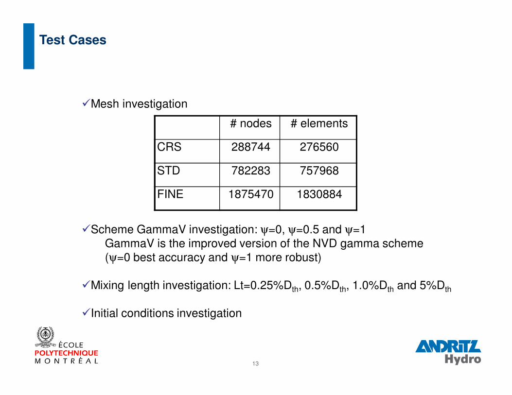
�Mesh investigation
�Scheme GammaV investigation: ψ=0, ψ=0.5 and ψ=1GammaV is the improved version of the NVD gamma scheme(ψ=0 best accuracy and ψ=1 more robust)
�Mixing length investigation: Lt=0.25%Dth, 0.5%Dth, 1.0%Dth and 5%Dth
�Initial conditions investigation
Test Cases
# nodes # elements
CRS 288744 276560
STD 782283 757968
FINE 1875470 1830884

14
�Mesh investigation
�Scheme GammaV investigation
�Mixing length investigation
�Initial conditions investigation
Test Cases
15
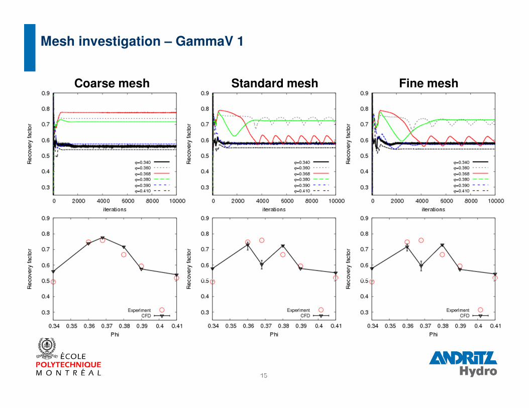
Mesh investigation – GammaV 1
Standard mesh Fine meshCoarse mesh
16
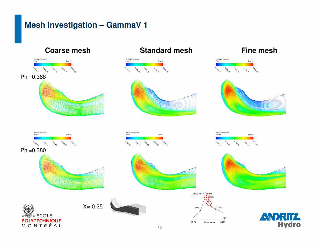
Mesh investigation – GammaV 1
Standard meshCoarse mesh Fine mesh
Phi=0.368
X=-0.25
Phi=0.380
17
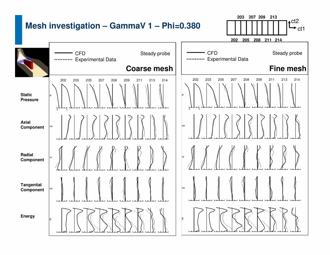
Mesh investigation – GammaV 1 – Phi=0.380
Static Pressure
AxialComponent
RadialComponent
Energy
TangentialComponent
CFDExperimental Data
Steady probe CFDExperimental Data
Steady probe
Fine meshCoarse mesh
202
207203
205
209
208
213
211 214
ct2ct1

18
�Mesh investigation
�Scheme GammaV investigation
�Mixing length investigation
�Initial conditions investigation
Test Cases
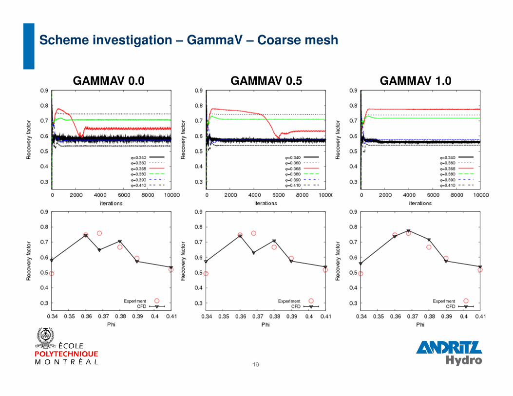
19
GAMMAV 0.5 GAMMAV 1.0GAMMAV 0.0
Scheme investigation – GammaV – Coarse mesh

20
�Mesh investigation
�Scheme GammaV investigation
�Mixing length investigation
�Initial conditions investigation
Test Cases
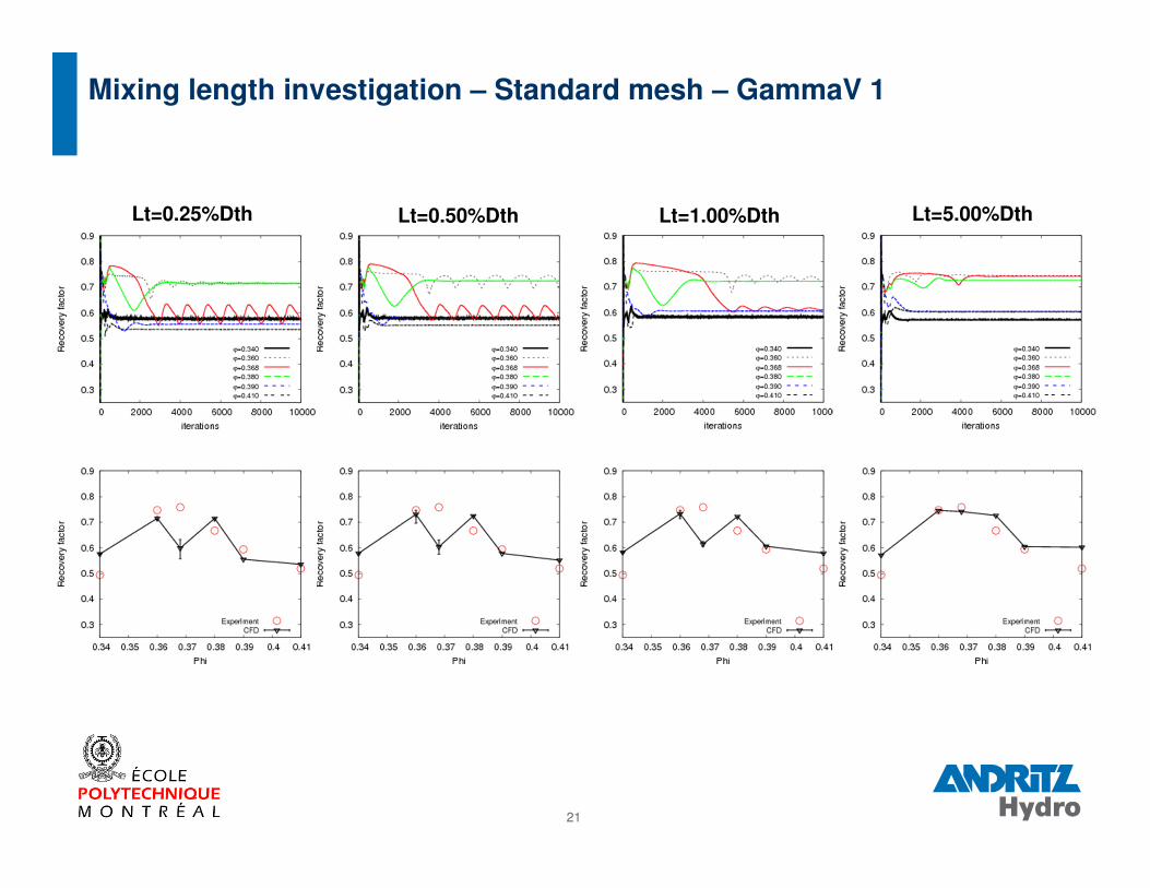
21
Mixing length investigation – Standard mesh – GammaV 1
Lt=0.25%Dth Lt=0.50%Dth Lt=1.00%Dth Lt=5.00%Dth
22
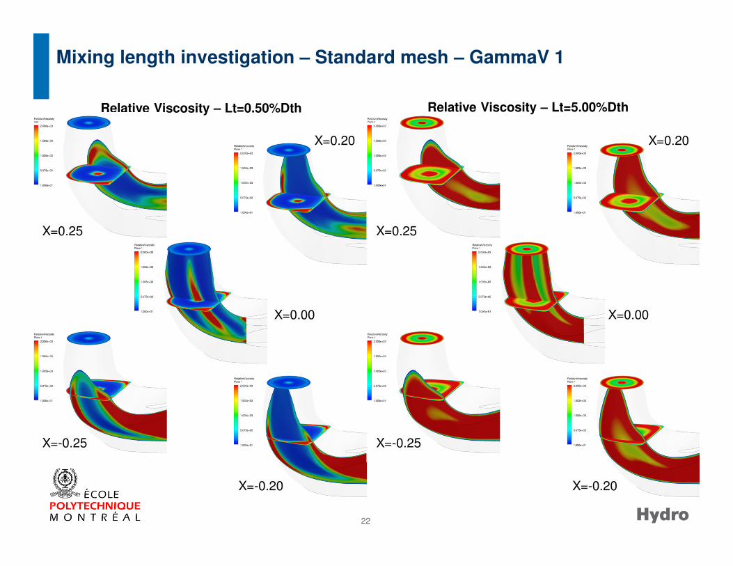
Relative Viscosity – Lt=0.50%Dth Relative Viscosity – Lt=5.00%Dth
X=0.25
X=-0.20
X=-0.25
X=0.20
X=0.25
X=-0.20
X=-0.25
X=0.20
X=0.00 X=0.00
Mixing length investigation – Standard mesh – GammaV 1

23
�Mesh investigation
�Scheme GammaV investigation
�Mixing length investigation
�Initial conditions investigation
Test Cases
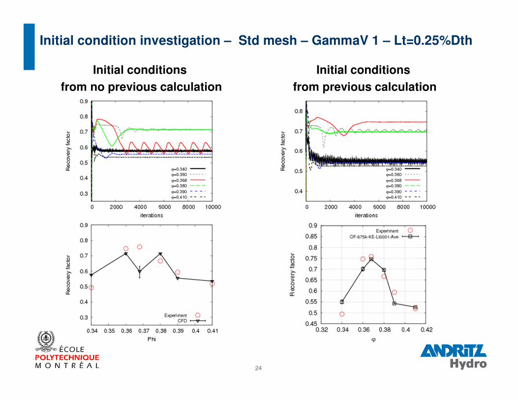
24
Initial condition investigation – Std mesh – GammaV 1 – Lt=0.25%Dth
Initial conditions
from no previous calculation
Initial conditions
from previous calculation
25
Conclusions
� Results are quite good compared to experimental data� Results are not so sensitive to mesh resolution except for Phi=0.368� Results are sensitive to scheme� Results are sensitive to initialization
Perspectives
� Validation and comparison with OpenFOAM-1.6ext� Runner and Draft-Tube calculations� Unsteady cases� Wall function investigation
Conclusions and Perspectives

26
Thank you for your listening
Any questions?