draft - transportation
TRANSCRIPT

REPORT NO. FRA/ORD- draft
EVALUATION OF LOCOMOTIVE CAB AIR FLOW METERS FOR TRAIN AIR BRAKE LEAKAGE MONITORING
D. R. AhlbeckS. M. Kiger*
BATTELLEColumbus Division 505 King Avenue
Columbus, Ohio 43201
*R & R RESEARCH, INC. 1373 Grandview Avenue Columbus, Ohio 43212
April 28, 1989
FINAL REPORT
TECHNICAL TASK NO. 4 CONTRACT NO. DTFR53-86-C-00006
Document is Available to the U.S. Public Through the National Technical Information
Service, Springfield, Virginia 22161
Prepared for
draft
U.S. DEPARTMENT OF TRANSPORTATION FEDERAL RAILROAD ADMINISTRATION
Washington, D.C. 20590

N O T I C E
The United States Government does not endorse products or manufacturers. Trade or manufacturers' names appear herein solely because they are considered essential to the object of this report.
NOTICE
This document is disseminated under the sponsorship of the Department of Transportation in the interest of information exchange. The United States Government assumes no liability for its contents or use thereof.

T echn ica l Report Docum entation Page
I . R e p o rt N o . 2. G ove rnm en t A c c e s s io n N o . 3. R e c ip ie n t ’ s C a ta lo g N o .
4. T i t le and S u b tit le
EVALUATION OF LOCOMOTIVE CAB AIR FLOW METERS FOR TRAIN AIR BRAKE LEAKAGE MONITORING
5 . R ep o rt D ate
April 28, 19896 . P e rfo rm in g O rg a n iz a tio n Code
7. A u thor's)
8 . P e rfo rm in g O rg a n iz a tio n R e p o rt N o .
Donald R. Ahlbeck and Steven-W. Ktger9 . P e rfo rm in g O rg a n iz a tio n N am e and A d d re s s
Battel!e *505 King Avenue Columbus, Ohio 43201
R & R Research, Inc. 1373 Grandview Avenue Columbus, Ohio 43212
10. Work U n it N o . (T R A IS )
11. C o n tra c t o r G ra n t N o .
DTFR53-86-C-00006
1 2 . S p o nso ring A g e n c y N am e and A d d re s s
Federal Railroad AdministrationOffice of Research & Development400 Seventh Street, S.W., Washington, D.C. 20590
13. T y p e o f R e p o rt and P e r io d C ove red
Final ReportOct 31, 1988-April. 30, 1989
14. S p o nso ring A g e n c y C ode
RRS-3215. S u p p le m en ta ry N o te s
16. A b s tra c t
Railroad freight train brake systems must be qualified for safe operation by meeting three brake pipe test criteria: (!) a minimum pressure of 60 psig at the. rear of the train, (2) a maximum pressure gradient of 15 psi; over the length of the train, and(3) a maximum leakage of 5 psi per minute after applying the brakes. With the advent of the pressure maintaining feature on brake control valves (26L equipment or equivalent),, the brake, pipe leakage limit became a less critical measure of the controllability of the train brake system. By the addition of an air flow meter or indicator to the locomotive control stand instrumentation, an alternative brake system leakage test, the air flow method (AFMJ, was possible. This method provides advantages in qualifying train brakes for operation in extreme cold weather, as well as a means for over-the-road monitoring of brake system leakage.
This report includes an extensive review of the technical literature and past experience with, the AFM. An engineering analysis of air flow meters was conducted in the context of the AFM. This analysis covers the accuracy and reliability of the meters, the required AFM calibration procedures, and the accuracy of the calibration devices themselves.
17. K e y Words
Air flow method, train air brakes, air flow meters, air flow indicators, brake system test
18. D is t r ib u t io n S to tem en t
Document available through the National Technical Information 5285 Port Royal Road Springfield, Virginia 22161
ce
19. S e c u rity C la s s i f . ( o f th is re p o rt) 20 . S e c u rity C la s s i f . (o f th is poge) 21* N o . o f P a g es 22 . P r ic e
Unclassified Unclassified 55
Form D O T F 1700.7 (8-72) R eproduction o f com p le ted page a u tho rize d

M E T R I C C O N V E R S I O N F A C T O R S
Approximate Conversions to Metric Measures9
Symbol When You Know Multiply by * To Find Symbol8
LENGTH
in inches •2.5 centimeters cm ~2_ft feet 30 centimeters cmyd yards 0.9 meters m ---- =mi miles 1.6 kilometers km —
AREA — E—
In2 square inches 66 square centimeters cm* — ~ft* square feet 0.09 square meters m2yd* square yards | 0.8 square meters m2 —mi* square miles 2.6 square kilometers km*
acres 0.4 hectares ha 5— —MASS (weight) — E
oz ounces 28 grams glb pounds 0.46 kilograms kg ~
short tons 0.9 tonnes t 4----(2000 lb) -E
VOLUME —E
up teaspoons 5 milliliters ml ij<ii
Tbsp tablespoons 15 milliliters ml 3—fl oz fluid ounces 30 milliliters mlc cups 0.24 liters ipt pints 0.47 liters 1qt quarts 0.95 liters 1gal gallons 3.8 liters ift* cubic feet 0.03 cubic meters m2 2 —yd* cubic yards 0.76 cubic meters m2
TEMPERATURE (exact) —
°F Fahrenheit 6/9 (after Celsius °c_
temperature subtracting temperature 1 ---- -32) —
*1 In. “ 2.64 cm (exactly). F o r other exact conversions end m ore deta il tables sea ~N B S M isc. Publ. 286. U n its o f W e igh t end Measures. Price $2 .26 S O C a ta lo gN o . C 1 3 10 286. inches
23Approximate Conversions from Metric Measures
22
21Symbol When You Know Multiply by To Find Symbol
20 LENGTH
19 mm millimeters 0.04 inches incm centimeters 0.4 inches In
18 m meters 3.3 feet ftm meters 1.1 yards yd
17 km kilometers 0.6 miles mi
16 AREA
16 cm* square centimeters 0.16 square inches in2m2 square meters 1.2 square yards yd*
14 km* square kilometers 0.4 square miles mi*ha hectares (10,000 m* I 2.6 acres
13MASS (weight)
■12
-11 g grams 0.035 ounces OZkg kilograms 2.2 pounds lbt tonnes (1000 kg) 1.1 short tons
-10
-9 VOLUME
-8 ml milliliters 0.03 fluid ounces fl oz1 liters 2.1 pints Pt1 liters 1.06 quarts qt-7 1 liters 0.26 gallons galm2 cubic meters 36 cubic feet ft*
-6 m2 cubic meters 1.3 cubic yards yd*
-5 TEMPERATURE (exact)
-4 °c Celsius 9/5 (then Fahrenheit °Ftemperature add 32) temperature
-3°F
-2 °F 32 98.6 212-40 0
1 1 1 1 1 1 1 140 80 1 1 1 1 I I
1 120 160 k 1 1 1 | 1 1
2001 1, l I I- 1 6
- CN101 1 1 20
fi i f r 140 60
i 1 1 80 100
cm
Oo0 37 °C

i
TABLE OF CONTENTS
PageEXECUTIVE SUMMARY ........................................... iii
1.0 INTRODUCTION ........................................... 1
2.0 TECHNICAL LITERATURE REVIEW ............................... 3
2.1 Federal Regulations ................................. 3
2.2 Train Brake System Operation ........................ 4
2.3 Air Brake System Flow and Leakage Relationships...... 7
2.4 Air Flow Test Method .................................. 12
2.5 Recent Brake System Studies ......................... 15
3.0 EVALUATION OF AIR FLOW METHOD ............................ 19
3.1 Air Flow Measurement ................................ 19
3.2 Operations and Experience with the AFM ............... 21
3.3 Air Flow Meter Calibration ...... 24
4.0 ENGINEERING EVALUATION OF THE AIR FLOW METHOD ........... 32
4.1 Air Flow Relationships .............................. 32
4.2 Error Analysis ....................................... 35
4.3 Air Flow Meter Accuracy Requirements ................ 42
4.4 Air Flow Meter Reliability .......................... 43
REFERENCES ..................................................... 44
APPENDIX A. AAR Specification M-980 ........................ 46
LIST OF FIGURES
Figure 2-1. Major Elements of a Freight Train Air Brake System 6
Figure 2-2. Correspondence of Air Flow to Brake Pipe Leakage
Rate by Train Length and Pressure Gradient ....... 9
Figure 2-3. Calculated Train Stopping Distance versus Brake
Pipe Pressure Gradient and Train Length .......... 11
Figure 2-4. Comparison of Leakage and Air Flow Methods of
Testing (Qualifying) Train Air Brakes ............. 14
Figure 2-5. Comparison of Leakage and Air Flow Limit Criteria.. 16
Figure 3-1. Sketch of Typical Air Flow Indicator Device ...... 20
Figure 3-2. Sketch of Calibrating Hose and Choke Assembly
Used by CN Rail .................................... 25

TABLE OF CONTENTS (Continued)
i i
Figure 3-3. Current Procedure for Calibrating Air Flow Meters
-- Burlington Northern Railroad ................... 27
Figure 3-4. Recommended Procedure for Calibrating Air Flow
Indicators -- Association of American Railroads ... 30
Figure 4-1. Three Types of Metering Device .................... 33
Figure 4-2. Sketch of AFM Measurement and Calibration ........ 34
LIST OF TABLES
Table 2-1. Brake Cylinder Pressure Build-up Time Versus Train
Length and Brake Pipe Leakage ..................... 10
Table 4-1. Effects of Main Reservoir Pressure Variations on
Air Flow Meter (Pressure Gauge) Readings .......... 38
Table 4-2. Effects of Main Reservoir Temperature Variations on
Air Flow Meter (Pressure Gauge) Readings .......... 39
Table 4-3. Effects of Barometric Pressure Variations on Air
Flow Meter (Pressure Gauge) Readings ............... 40
Table 4-4. Effects of Brake Pipe Air Temperature Variations on
Calibration Device Air Flow Rate ................... 41
EXECUTIVE SUMMARY
Railroad freight train brake systems must be qualified for safe
operation by meeting three brake pipe test criteria: (1 ) a minimum
pressure of 60 psig at the rear of the train, (2) a maximum pressure
gradient of 15 psi over the length of the train, and (3) a maximum
leakage of 5 psi per minute after applying the brakes. With the advent
of the pressure maintaining feature on brake control valves (26L equip
ment or equivalent), the brake pipe leakage limit became a less critical
measure of the controllability of the train brake system. By the
addition of an air flow meter or indicator to the locomotive control
stand instrumentation, an alternate brake system leakage test, the Air
Flow Method (AFM), was possible. This method provides advantages in
qualifying train brakes for operation in extreme cold weather, as well as
a means for over-the-road monitoring of brake system leakage.
Based on the results of laboratory tests of full-scale train
brake systems in the early 1970s, the Canadian railways initiated field
tests of the AFM in 1974. Since December 1978, the AFM has been used
system-wide on the Canadian railways. The method was officially
sanctioned by the Canadian Transport Commission on April 30, 1984, as a
substitute for the brake pipe leakage rate test when the controlling unit
of the locomotive has a pressure-maintaining brake control valve. Over
the past several years, certain railroads in the United States have
gained experience with the AFM under waiver from the FRA. The extensive
experience by both the Canadian and U.S. railroads has uncovered no train
safety-related problems with the AFM. The use of the AFM has allowed the
operation of longer trains (estimated from 10 to 15 additional cars) in
cold weather, and the use of air flow indicators in over-the-road
operations has allowed continuous monitoring of train brake system
condition. This use has received favorable commentary from the train
crews.
This report includes an extensive review of the technical
literature and past experience with the AFM. An engineering analysis of
i i i

air flow meters was conducted in the context of the AFM. This analysis
covers the accuracy and reliability of the meters, the required AFM
calibration procedures, and the accuracy of the calibration devices
themselves.
The currently-used air flow meters are differential pressure
gauges that measure the pressure drop across a 19/64-inch metering
orifice. The flow measurement is therefore nonlinear, varying as the
square-root of the pressure drop. This results in large changes in air
flow per gauge face division at the low end of the scale, and relatively
small changes in flow per division at the high end of the scale. The air
flow meters are calibrated at 60 standard cubic feet per minute (scfm),
which has been established by the industry as a safe leakage flow limit.
This calibration point is set mid-range on the meter to minimize the
effects of the nonlinear behavior.
With the use of a differential pressure gauge to measure air
flow, the air flow indicator reading accuracy is dependent (in addition
to the basic gauge accuracy) on three factors: (1 ) main reservoir air
pressure, (2) main reservoir air temperature, and (3) atmospheric
(barometric) pressure due to altitude. The compressor is set to cycle
main reservoir pressure over a 1 0-psi range, which produces a 2 cfm
change in reading at the nominal 60 scfm calibration air flow. A range
of air temperatures causes similar changes in flow reading for an actual
flow rate of 60 scfm. Since both the metering orifice and calibration
device produce similar changes, however, the calibration reading (or a
comparable leakage reading) would remain the same at any temperature, in
itself an error. The combination of these errors produces a probable
(rms) error range of _+ 2.7 cfm, which exceeds the required accuracy
limits of AAR Specification M-980 for air flow indicators.
The AAR Calibration Procedure for AFM Type Air Flow Indicators
(RP-402) minimizes the "temperature independence" of the metering devices
by requiring that the calibration device provide 60 cfm [0.0764 lb/sec]
at a temperature no greater than 20 F. This requirement minimizes the
iv

air flow reading error at lower temperatures, where actual leakage is of
greater significance.
Currently both the leakage rate test and air flow test methods
rely on standard air pressure gauges to qualify the train brake system
for service. In the use of differential pressure gauges as air flow
indicators, the industry has chosen a rugged and reliable device with a
long history in locomotive service. The air flow indicator can be
maintained on the same 92-day cycle as the other air pressure gauges in
the locomotive cab.
v

FINAL REPORT
DRAFT,on
EVALUATION OF LOCOMOTIVE CAB AIR FLOW METERS FOR TRAIN AIR BRAKE LEAKAGE MONITORING
by
Donald R. Ahlbeck and Steven M. Kiger*
April 28, 1989
1.0 INTRODUCTION
The Federal Railroad Administration (FRA) has been petitioned
by several railroads to modify 49 CFR 232 to permit the use of cab air
flow meters to conduct initial terminal and road train air brake leakage
tests. Current rules require that train brakes meet three criteria at
the initial terminal, and at a point other than a terminal where one or
more cars are added to the train:
• A minimum brake pipe pressure of 60 psi at the last car of
the train,
• A maximum pressure gradient of 15 psi over the length of
the train, and,
• A maximum leakage of 5 psi/min measured 30 to 60 seconds
after exhaust ceases from a 15-psi service reduction
(brake setting), with the brake valve pressure-maintaining
function off.
The leakage rate test is a measure of the controllability of
the train brake system, assuming a system not equipped with a pressure
maintaining valve. Widespread use of pressure maintaining valves on
modern locomotive units, plus the addition of air flow meters, may make
increased leakage rates practical without adverse effects on operations
TECHNICAL TASK NO. 4CONTRACT NO. DTFR53-86-C-00006
★ R & R Research, Inc., Columbus, Ohio

2
safety. This could increase railroad productivity in colder climates,
where leakage rates can be a problem in winter. A flow-related test
would evaluate system leakage, not just the brake pipe leakage. In
addition, use of the on-board flow meter can provide continuous
monitoring of brake system functions during over-the-road operation.
Canadian railroads have conducted tests with brake pipe air
flow measurements, establishing a 60 scfm leakage flow rate limit. These
railroads have over ten years operational experience using the flow,
rather than pressure rate, leakage limit. The use of air flow meters can
be particularly beneficial during cold weather when brake pipe leakage is
at a maximum. The use of 60 scfm as a criterion for satisfactory brake
system leakage permits the railroads to operate longer trains during cold
weather. Several U.S. railroads, including the Burlington Northern, have
obtained authority to test the use of flow meters.

3
2.0 TECHNICAL LITERATURE REVIEW
2.1 Federal Regulations
Current Federal Railroad Administration, DOT regulations
apropos of train air brake tests are contained in Part 232 - Railroad
Power Brakes and Drawbars of 49 CFR Ch. II (10-1-87 Edition)[Ref. 1]. In
Section 232.12 Initial terminal road train airbrake tests, the regulation
states:
(b) "...inspection will be made to determine that -
(1) Brake pipe pressure leakage does not exceed five pounds
[psi] per minute..."
(d)(1) "After the airbrake system on a freight train is charged
to within 15 pounds [psi] of the setting of the feed valve on
the locomotive, but not less than 60 pounds, as indicated by an
accurate gauge at rear end of train,...and upon receiving the
signal to apply brakes for test, a 15-pound brake pipe service
reduction must be made in automatic brake operations, the brake
valve lapped, and the number of pounds of brake pipe leakage
per minute noted as indicated by brake pipe gauge,..."
(d) (3) "When the locomotive used to haul the train is provided
with means for maintaining brake pipe pressure at constant
level during service application of the train brakes, this
feature must be cut out during train airbrake tests."
(e) "Brake pipe leakage must not exceed 5 pounds per minute."
In Section 232.13 Road train and intermediate terminal train
air brake tests, the leakage test is similarly described:

4
(d)(1) "At a point other than a terminal where one or more cars
are added to a train, after the train brake system is charged
to not less than 60 pounds as indicated by a gauge or device at
the rear of a freight train..., a brake test must be made to
determine that brake pipe leakage does not exceed five (5)
pounds per minute as indicated by the brake pipe gauge after a
2 0-pound brake pipe reduction."
The additional five pound reduction in brake pipe pressure (20, instead
of 15) makes the intermediate-point leakage test a little less severe,
but allows combining with the leakage test the test that train brakes at
the rear will apply.
In a related regulation, Section 232.19 End of train device,
the accuracy of the pressure-measuring device is addressed:
(b)(1) "Capable of measuring the rear car brake pipe pressure
with an accuracy of +3 psig and brake pipe pressure variations
of + 1 psig [resolution]...".
The regulation also defines the operating environment of the
rear unit (d) and the front unit (f), in terms of temperature, humidity,
altitude, shock and vibration.
\2.2 Train Air Brake System Operation
Train air brake system operations and testing procedures are
described in a definitive 1971 technical paper by Blaine and Hengel [Ref.
2]. This paper describes the basic elements of the air brake system, as
well as the effects of brake operations and test procedures on train
performance.
The basic car-mounted unit of the air brake system consists of
the brake pipe, a control valve, auxiliary and emergency air reservoirs,
the brake cylinder, and mechanical linkages to the brake shoes. These

5
elements are shown in Figure 2-1. The brake pipe forms the train-common
air pressure source and pressure communications line. The train brake
system is charged by locomotive-mounted air compressors to the nominal
brake pipe pressure setting, usually 75 to 90 psig at the locomotive
control valve, depending on local operating procedures. This brake pipe
pressure will droop with distance toward the rear of the train (the
"gradient") due to flow-induced pressure losses, depending on localized
leakage in hose couplings, fittings, etc.
Operation of the train brakes is initiated by reducing the
brake pipe pressure by blowing off air through the automatic brake valve
in the locomotive. A "service reduction" consists of a brake pipe
pressure reduction of 5 to 25 psig. A "full service reduction" is one
sufficient to cause pressure equalization between the brake cylinder and
the auxiliary reservoir. Individual car control valves will sequentially
sense the pressure drop and divert air from the auxiliary reservoir to
the brake cylinder, building up cylinder pressure and braking force on
the wheels. These valves are sensitive to the rate of brake pipe
pressure drop: a 20-psi drop in more than about 1.4 seconds constitutes a
normal service application of brakes, while a drop of 20 psi in less than
about 1.2 seconds will induce an emergency brake application. Normal
quick-service brake action (type ABD or ABDW valves) propagates toward
the rear at 400 to 600 feet per second, while an emergency application
will propagate at 900 to 950 ft/second.
Typical brake action times are cited in the paper. For a
single car, a full-service reduction in brake pipe (BP) pressure from 80
to 55 psig will bring the brake cylinder (BC) pressure from 0 to 50 psig
in about 10 seconds, and to 57 psig in 15 to 16 seconds. For a 150-car
train with minimum leakage, BP pressure at the first car drops to 60 psig
and the BC pressure rises to about 48 psig at roughly 55 seconds. At the
150th car, the BP pressure drops to 60 and the BC pressure rises to about
46 psig in roughly 125 seconds. Since slack action propagates at 200 to
400 ft/second, the reason for generation of slack run-in during braking
of long trains becomes apparent.

6
Source: R. L. Wilson [Ref. 4]
AUXILIARY LEVER
ABDW CO NTRO L VALVE
RELEASE ROD
C O M B IN ED D IRT COLLECTOR AN D CU T OUT CO CK
■ R A K E SHO E
Source: Slmmons-Boardman, The Car and Locomotive Cyclopedia, 1984
FIGURE 2-1. MAJOR ELEMENTS OF A FREIGHT TRAIN AIR BRAKE SYSTEM

7
2.3 Air Brake System Flow and Leakage Relationships
Air flow and leakage in the train brake system have several
important effects on brake testing, operation and response. The paper by
Blaine and Hengel [2] makes several salient points with regard to brake
system leakage:
Train air leakage is checked after making a 15 [or 20]
psig BP reduction, setting the brakes, and timing the BP
gauge drop over one minute. However, this measures only
brake pipe leakage. With the brakes released, air leakage
of control valves and reservoirs are added to give total
"system" leakage.
Brake pipe leakage over 5 psi/min or gradients over 15 psi
can cause erratic brake response (undesired applications
or releases, or brakes may not respond).
Leakage in the rear of the train has the more significant
effect on train brake operations, therefore there is more
benefit if corrected.
Train length affects BP reduction time and train average
BC pressure. Leakage tends to speed up BP reduction.
Therefore, leakage-induced gradient reduces available
pressure, but leakage speeds up application time. The
effect increases notably with train length. Leakage up to
about 5 psi/min produces shorter stops. At 8 to 10
psi/min of BP leakage, stopping distance is adversely
affected.
The practical limit for satisfactory brake control is a
leakage and gradient situation where flow demand in a
full-charge condition is less than 60 cubic feet per
minute (cfm).

8
In an undated paper by R. L. Wilson entitled "Factors Affecting
Air Brake Operation" [Ref. 3], the effects of leakage, pressure level and
train length are explored in terms of train charge time, brake
application time, and pressure gradient. A later (1976) paper by the
same author, "Leakage and Gradient Considerations in Train Braking" [Ref.
4] presents results from the Westinghouse Air Brake Division (WABCO) 150-
car test racks under laboratory conditions. In these tests, an 80 psig
BP pressure at the source (brake valve) was used, with 50 feet of brake
pipe per "car" and evenly-distributed leakage. Results of these tests
were used to determine (1 ) train gradient and resulting air flow, (2 )
brake cylinder application time, (3) brake cylinder pressure buildup
time, (4) average train brake cylinder pressure, (5) simulated train
stopping distance, and (6) release and recharge times. Results were
plotted for various brake pipe lengths (number of "cars") up to 7500 ft
(150 cars).
A correspondence between brake valve air flow and evenly-
distributed brake pipe leakage is shown in Figure 2-2, based on Figure 2
of Wilson's paper. In this "carpet plot", both train length (solid
lines) and pressure gradient (dashed lines) are shown. For a given flow
and leakage, leakage concentrated toward the front of the train would
produce less pressure gradient, while leakage concentrated toward the
rear would create a higher gradient. Although not specifically stated,
leakage is assumed to be measured by the AAR method, after a 15-psi
service reduction in BP pressure and a 30 to 60-second time delay. It
was noted that higher leakage values for given flow rates were implied in
the pressure gradient values cited by Blaine and Hengel [2]. However,
the laboratory rack test data reported by Wilson [4] were confirmed by
tests conducted during January 1978 by CN Rail Operations at Transcona,
Manitoba, cited in J. G. Smith's paper of October 1978 [Ref. 5].
Wilson's paper [4] explores brake cylinder pressure build-up
time at the last car as a function of brake pipe leakage and train
length. The tests showed distinct time minima, particularly with longer
train lengths, as shown in Table 2-1:

AIR
FLOW
(CFM)
9
F IG U RE 2-2 . CORRESPONDENCE OF A IR FLOW TO BRAKE P IP E LEAKAGE RATEBY TRAIN LENGTH AND PRESSURE GRADIENT

10
TABLE 2-1. BRAKE CYLINDER PRESSURE BUILD-UP TIME VERSUS VERSUS TRAIN LENGTH AND BRAKE PIPE LEAKAGE [4]
No. Cars Time (sec) BP Leakage (psi/min)
51 38 12.3
76 53 1 1 . 2
1 0 1 85 7.3
150 1 1 1 4.5
The minimum brake cylinder pressure build-up time occurred at
about the same BP pressure gradient, 5 to 7 psi. Similar effects were
found for brake application time. These data were used to determine
average train brake cylinder pressures and to calculate train stopping
distances for a full service brake application. Calculated stopping
distances are plotted in Figure 2-3 versus initial gradient, flow and
leakage for different train lengths of loaded 1 0 0-ton cars from an
initial speed of 50 mph. From a train safety viewpoint, it is noted that
the curves are relatively "flat", and some variation in BP pressure
gradient and leakage can be tolerated.
Other aspects of brake pipe leakage and pressure gradient are
brake release time and reservoir recharge time, both of which increase
sharply with increased gradient and train length. A longer recharge time
increases the time during which a "false gradient" exists within the
train, which can cause undesired brake release during repeated brake
applications. Recharge time to within two psi of brake pipe pressure can
take typically 15 to 30 minutes at the last car, following a full service
reduction.

11
8
ooo
£ 5
c_>
fT\ Iq
C3
CL
p 3tn
0
TRAIN LENGTH
iso
<cv
80 PSIG BP PRESSURE
50 MPH INITIAL SPEED
LOADED 100-T0N CARS
7% NET DESIGN BRAKING RATIO
FULL SERVICE (25 PSI) REDUCTION
ABD & 26 EQUIPMENT
SOURCE: WILSON [REF. 4]
0 5 10 15 20
BP PRESSURE GRADIENT (PSI)
25
FIGURE 2-3. CALCULATED TRAIN STOPPING DISTANCE VERSUSBRAKE PIPE PRESSURE GRADIENT AND TRAIN LENGTH

12
2.4 Air Flow Test Method
The 1978 papers by Smith [Ref. 5] and Wickham [Ref. 6] address
the air flow alternative to the pressure-drop leakage test. Several
pertinent observations are made in these papers:
• Pressure maintaining valves [the 26-L locomotive brake
equipment or equivalent] appear to be the key development,
where BP pressure will stay where the locomotive engineer
sets it, thus avoiding increasing brake cylinder pressures
and braking forces as BP pressure falls due to leakage,
and consequently the periodic release and reapplication of
train brakes.
• BP leakage allowance cannot simply be raised to, say, 8
psi/min to take advantage of the pressure maintaining
feature. Continuous quick-service valves have a stability
level a little over 5 psi/min, and accelerated application
valves about 7 psi/min. During a leakage test, a true
leakage of 8 psi/min would cause some valves to operate,
giving a false leakage of perhaps 1 1 psi/min.
• BP pressure drop tests only BP leakage after a 15 psi
reduction, whereas air flow tests total system leakage at
the full BP pressure.
• Trains with non-maintaining valves have to meet the 5
psi/min leakage controllability limit, while trains with
maintaining brake valves can utilize the 60 cfm flow
controllability limit.
• For most trains, the Air Flow Method (AFM) would normally
take longer than the BP leakage method, since the 15 psi
gradient is usually not the final stabilized value. For
longer trains, where the 15 psi gradient is the deciding

13
factor, the AFM would save time. The "break-even" point
is about 147 50-ft cars.
• The AFM can "allow trains to be put into service which
otherwise might be rejected for no good reason".
Computer predictions of the effects of leakage distributions
are given in a 1979 paper by Schute [Ref. 7]. Results showed that...
• Brake pipe pressure gradient is sensitive to location of
leakage in a train, increasing as leakage moves rearward.
• For leakage less than about 10 psi/min, brake pipe flow is
not sensitive to the distribution of leakage.
Both References 6 and 7 cite air flow levels less than
Reference 4 (or the corroborating field tests of Reference 5) for the
given leakage rate of pressure gradient.
The extensive 1981 report on the Air Flow Method by CN Rail
Operations to the Canadian Transport Commission [Ref. 8] covers the
background of the AFM, tests, railway experience, training, operations,
and economic factors. One section (2.17) provides a direct comparison of
the Leakage and Air Flow Methods of testing train air brakes. This
comparison is given in Figure 2-4 and contains basically the same
important points cited in the above references. Economic benefits
identified by CN Rail in the three years following implementation of the
AFM included a 15.4 percent increase in the winter train load, resulting
in crew wage savings, diesel unit and caboose mile savings. Identified
annual operating savings exceeded $6M Canadian. Additional savings were
projected (but not quantified) for motive power and caboose acquisitions,
revenue freight car requirements, and plant capacity.
The Air Flow Method is also cited in a 1981 paper by Blaine,
Hengel and Peterson [Ref. 9] in the section titled "determination of a

Brahe F iW U « k i« » T « l t
14Air Flow Method Test
a) Test it aade in an unrealistic a)Banner unrelated to operating procedures, i.a. pressure aainteining feature is "cut out".
b) Test is Bade at IS psi less than b) the standard working brakepipe pressure for the train
c) Only brake pipe and branch pipes c) arc tested for AB equipment.Auxiliary and Caergency reservoirsand control valve are not tested for leakage.
d) Test only determines the rate of d) brake pipe pressure drop as indicated by the loeoaotive gauge, with no indication given ofthe capacity of the loeoaotive to supply air.
e) Test is awkward and difficult a)because it requires reading aaoving gauge needle and coordinating with a watch after establishing the correct aoaent or "wait period" to conence the readings after cutting out pressure aaintaining.
f) Test is clearly not aeaningful. f)It is possible to have a 100car train with a leakage rate which fails the test but if a block of cars is reaoved, the shorter reaainiog train aay easily have a higher leakage rate. This effect is due to the variables in concentration of leaks end voluae of train brake pipe froa which air is escaping.
The reverse situation can also occur where leakage rate can be decreased by adding blocks of cars.
g) Test of leakage rate cannot be Bade g) while the train is aoving and thereis no reference aark to relate changes in conditions.
h) Test originated in the days of the h) ateaa loeoaotive, without Pressure Maintaining or Brake Pipe Flow Indicators and with older designs ofcar brake eysteas. Test inhibits iaproveaents in aquipaent designs.For today this antiquated aethod results in decreased transportation efficiency and increased train delays and attendant fuel eonsuaption. Plant capacity is severely restricted.
Test is aade with the brake systea in the saae condition and with the saae operations as noraally used when braking a train anroute.
Test for flow aade at the full working brake pipe pressure for the train.
Brake pipe, brake branch pipe, caergency and auxiliary reservoirs and control valve are tested for leakage.
Test indicates the flow of air to the entire train brake systea aeasured at its origin, the loeoaotive regulating valve, and relaees to the capacity to aupply air.
Test is siaple and clear.
The 60 CFM liait is used as an indication of the ability of the autoaatic brake valve to charge the brake systea of the train. Train site is regulated by flow and gradient.
Peraits constant enroute aonitoring of CFM, with a asaningful reference aark to relate changes in conditions.
Tssts take advantage of availablity of aodern technological advances in air brake equipaent. Use of this equipaent and test aethod will perait increased transportation efficiency end reduced fuel eonsuaption. This has a aajor econoaic effect and also increases plant capacity to permit the railways to handle increased traffic.
FIGURE 2-4. COMPARISON OF LEAKAGE AND AIR FLOW METHODS OF TESTING (QUALIFYING) TRAIN AIR BRAKES

15
satisfactory train [brake system] condition". Two figures in this paper
show the relationships of brake pipe pressure gradient, air flow and
leakage to train (brake pipe) length for both the leakage and AFM tests.
These are repeated in Figure 2-5. Here, the flow versus leakage values
are in close correspondence with those cited by Wilson [4] and shown in
Figure 2-2. The authors state: "The validity of the 60 cfm limit has
been the subject of extensive service trials and the AFM has been used
over a three-year period for over 1 ,0 0 0 ,0 0 0 initial and intermediate
terminal train tests on Canadian railways."
Several presentations on operating experience with the AFM have
been made in recent years to The Railway Fuel and Operating Officers
Association [Refs. 5,10,11,12]. In addition to CN Rail [5,10] and CP
Rail [11], experience gained by the Burlington Northern and Soo Line
Railroads were also presented in these papers. Operating experience
included reports by locomotive engineers and a sampling of train brake
tests by both methods for direct comparison. No problems in train
handling or train safety were found attributable to the AFM.
2.5 Recent Brake System Studies
The Federal Railroad Administration has sponsored several
recent freight train brake system safety studies aimed at a better
understanding of brake system operations and train dynamic response. One
of these studies [Ref. 13] addressed two items (among several others)
under brake system dynamic performance that touch on the Air Flow Method:
a. "Study the feasibility of requiring locomotives to be
equipped with brake pipe flow indicators to enable
engineers to measure trainline air flow." [NTSB Safety
Recommendation R-79-85, January 10, 1980.]
b. "Can train leakage be increased at the initial terminal
brake test over the present 5 psi per minute safely?"

16
a. Leakage, Gradient versus Train Length (B.P. Leakage Test)
b. Air Flow, Gradient, Leakage Limits versus Train Length
Source: Blaine, Hengel, Peterson [Ref. 9]
FIGURE 2-5. COMPARISON OF LEAKAGE AND AIR FLOW LIMIT CRITERIA
B.P. GR
ADIE
NT-B
AR

17
In this study, pressure gradient, leakage and train stopping
distance models were developed. Conclusions reached were essentially the
same as the previous references cited:
• Increased leakage rates are possible only because of the
widespread adoption of pressure maintaining valves and
flow meters on locomotives.
• The leakage rate test is a measure of controllability of a
brake system, assuming the system is not equipped with
pressure maintaining equipment.
• A relaxed leakage rate test (7 psi/min) would not
compromise controllability with pressure maintaining
equipment, but some valves would operate, increasing the
leakage and nullifying the test.
• Air flow would test for system leakage, whereas the
current method tests only for brake pipe leakage
[typically 70 percent of total system leakage].
• A flow rate meter allows continuous monitoring of the
brake system.
• The air flow rate method is more straight-forward, with
less room for error.
A simple formula was developed for pressure drop (in the
leakage test) versus time, as an exponential decay in pressure. The time
constant in this formula varies as the inverse square-root of absolute
temperature, so that for a fixed leakage area the warmer the brake pipe
air, the faster the pressure drop. This time constant may vary by 15 to
20 percent over typical winter-to-summer temperatures. However, leakage
area generally increases at colder temperatures, tending to offset this
change in time constant.
18
Other efforts toward the mathematical modeling of train air
brake systems have been reported [Refs. 14-18]. The most recent (1988)
publication by Abdol-Hamid, Limbert and Chapman [Ref. 18] entitled "The
Effect of Leakage on Railroad Brake Pipe Steady State Behavior" discusses
a mathematical model for pneumatic transmission lines (the brake pipe)
with leakage. This model utilizes one-dimensional continuity and
momentum equations, using finite-difference techniques for solution. The
conclusions of this study include the following:
• Pressure gradient is larger as the leakage moves toward
the rear.
• For small leakage (< 2 percent), leakage location has
little effect on flow rate ; for larger leakage (> 8
percent), there is increased flow as leakage moves
forward.
• Leakage size has great effect on the pressure
distribution.
• Larger leakage size (> 8 percent) does not have a great
effect on inlet flow, since pipe friction tends to control
flow.
• Fitness of the brake pipe cannot be determined based on
pressure gradient or on flow alone: both must be used.
A recent study, "The AAR Undesired Emergency Study" [Ref. 19]
was reviewed in the context of the Air Flow Method of train brake
qualification. None of the conclusions in this study of undesired
emergency applications of train brakes indicated that the AFM would in
any way jeopardize brake system integrity or train safety.

19
3.0 EVALUATION OF AIR FLOW METHOD
3.1 Air Flow Measurement
Air flow measurements in locomotive air brake systems are made
currently by measuring the pressure differential across an orifice in the
main reservoir supply pipe to the brake valve. The air flow indicator
is, therefore, an air pressure gauge, usually of the bourdon tube type.
The gauge is connected across an A-19 Flow Indicator Adapter, which is a
drilled orifice in a spring-seated check valve (to allow unrestricted air
flow during brake system charging), or across a 19/64-inch diameter
orifice plate. A typical air flow indicator is shown in the sketches of
Figure 3-1.
The air flow through an orifice varies by the square-root of
the pressure differential across the orifice. Therefore the linear scale
on the indicator face (numbers 2 through 14) relate to flow in a highly
nonlinear way. For example, tests have shown a change in flow of 18
cubic feet per minute (cfm) between marks 2 and 3, and only 4 cfm between
marks 7 and 8 . Fortunately, the device becomes more sensitive to change
in flow in the range near the AFM test limit of 60 cfm, which falls near
mark 8 . The device will generally run off-scale during brake system
charging, but is protected internally and by the A-19 adapter from damage
during this part of normal operation.
Air flow through an orifice is also dependent on the source
(main reservoir) pressure and temperature, varying as a “constant" times
the square-root of pressure divided by the square-root of absolute
temperature. (The "constant", which consists of the orifice discharge
and expansion coefficients, may also vary, depending on air velocity.)
These factors can affect the readings of the device.
The air flow indicator (pressure gauge) is generally maintained
by the railroads with the same frequency and standards established for
other air pressure gauges in the locomotive cab.

20
Source:
FLOW INDICATOR WITH MOUNTING BASEV N ADJUSTABLEBLACK HED
® !fL / O i i r i - 0 \ m o v a b l e ( D ^ / x ^ ' J . v \ \ r e f e r e n c e
PO IN TER
®
W H IT EINDICATORPO IN TER
®
l e n sr e t a in e r
C L IP
Q u i c kD I S C O N N E C T
M O U N T I N G B A S E
FIGURE I
OPTIONALRED INDICATOR
L IG H T (LED )
ADJUSTING STEM PON PINE ADJUSTMENT OP APM POINTER
m i t/st* t u n —tiicii
CROSS SECTION OF PRESSURE CHAMBERPR ESSU R ECHAM BER
©GAUGE
MOVEMENTA SSEM B LY
©
EOUALlZlNG v a l v e L IM IT S THE MAXIMUMd if f e r e n t ia l p r e s s u r eBETW EEN THE INSIDE AND OUTSIDE OF THE BOURDON TUBE
A - 19 A D A P T O R O R 19/64 O R IF IC E P L A T E
FIGURE II
Salem 796 Series, Bulletin 95 (Graham-White Sales Corp.)
FIG U RE 3-1 SKETCH OF TYPICAL A IR FLOW INDICATOR DEV ICE

21
3.2 Operations and Experience with the AFM
Railways in Canada are currently authorized to use the AFM
under Order No. R-36502, dated 30 April 1984, of the Railway Transport
Committee, Canadian Transport Commission. The Order established the
following standards for the AFM:
1. "The train and engine crew must have been instructed as to
how to conduct the Air Flow Method brake test."
2. "The controlling motive power unit of the train to be
tested must be equipped with schedule 26-L brake equipment
or the equivalent and must have a pressure maintaining
feature in operating condition."
3. "The controlling motive power unit of the train to be
tested must have a Brake Pipe Flow Indicator which is
calibrated to indicate a flow of 60 cubic feet per
minute."
In addition to instructions for AFM tests at initial and
intermediate terminals, and road tests, Schedule "B" of the Order states:
"When a train operating under AFM Rules experiences an increase
in brake pipe air flow and/or brake pipe gradient above the
permissible limits (other than normal brake application and
release) the employee in charge shall take appropriate action
to repair leaks, if possible, set off cars, if necessary, or
operate with due caution to the next point where inspection and
corrective action can be taken, having full regard for safety
and train brake handling."
Several U.S. railroads have received authorization from the FRA
to conduct the Air Flow Method of testing and qualifying freight train
brakes. Experiences of two of these railroads were given in the 1983

22
presentation by Fiedler and Fry [12] to The Railway Fuel and Operating
Officers Association. In this presentation, comments are given on the
AFM in the context of brake tests, air flow meter calibration, and
operating experiences on both the Burlington Northern and Soo Line
Railroads. Some conclusions are: "Over 6000 AFM tests [1983] have been
performed on BN trains...To date, there has [sic] not been any
difficulties reported associated with AFM testing" (BN), and "...the Air
Flow Method has been accepted readily by our on-train employees. The
engineers are extremely pleased with their capability of now being able
to monitor their train line while enroute" (Soo).
As part of this study, several railroads were contacted to
determine their current experience with, and/or opinions on the AFM. The
following comments were noted:
Burlington Northern. BN engineers routinely use the flow meters to
monitor the train brake system over-the-road. Apparently the flow meters
were introduced on the BN predecessor Great Northern Railway by Mr. Jim
Herrin, who later went to the Penn Central (Conrail predecessor) and
introduced it there before retiring. Operations personnel on BN have not
reported any problems with either the AFM or the flow meters. BN has
established operating, calibration and maintenance procedures, which are
given in the BN "Air Brake, Mechanical and Train Handling Rules", Form
15338 - Revised 2/1/87.
BN has not tried to quantify the cost benefits: the AFM does
not really save time in the yards, and it costs money to apply, calibrate
and maintain the flow meters. However, it is a proven tool in
operations, and it can allow short, leaky trains to be run in cold
weather.
Conrai1. Conrail has equipped 100 percent of their locomotives having
the 26L brake valves with air flow meters (about 75 percent of the total
fleet). Conrail has conducted AFM tests for the last two winters, and no
problems have been experienced [these have, however, been relatively mild

23
winters]. Both AFM and pressure drop (leakage) air brake tests were run
during this period on about 30,000 trains. Not one instance was reported
of train handling problems enroute after an AFM test qualification. From
the data, less than 1 / 2 percent of the trains indicated greater than a 10
psi pressure gradient.
Conrail has established operating, calibration and maintenance
procedures. They have achieved high consistency and repeatability in the
calibrations. The key, they feel, is a complete understanding by shop
forces of the procedure: for example, that setting the calibration marker
must be done with rising main reservoir pressure (see Section 3.3). Both
WABC0 and Graham-White (Salem) air flow meters are currently used.
Maintenance problems with air flow meters have been virtually non
existent. Calibration is done with purchased orifices certified for 60
scfm calibration at a 90 psig brake pipe and 125 psig (rising) main
reservoir pressure.
Cost benefits have not been quantified, but it is felt that
costs can be reduced, since longer trains can be run in the winter
(perhaps 10-15 additional cars). There are generally no time-savings,
since the train gradient must still be met before AFM tests, and the
train line (gaskets, etc.) must be "worked over". The AFM is viewed as
oriented more toward train handling safety than just a leakage test.
Union Pacific. UP experience is similar to the BN. Between 30 to 40
percent of locomotive units are equipped with Salem air flow meters. For
now, the UP has put on hold any effort to get a waver from the FRA. The
respondent was not sure that UP has yet developed procedures for
operations, calibration and maintenance. The engineers like the air flow
meters (which, however, are not calibrated), and no problems have been
reported.
Denver & Rio Grande Western. Air flow meters are not in use, and there
are no plans to use them. D&RGW feels that the end-of-train devices
(rear-end brake pipe pressure) are a better way to determine train brake

24
system condition.
Southern Pacific. SP uses air flow meters, but not on all units.
Atchison, Topeka and Santa Fe. ATSF does not currently use air flow
meters, and has not for a number of years. Cost control was cited as the
probable reason.
CSX Transportation. CSX does not buy air flow meters for their
locomotives, and has adopted a "wait and see" position with respect to
testing and use of the AFM.
3.3 Air Flow Meter Calibration
3.3.1 Canadian National
Procedures for calibration of air flow meters are given by CN
Maintenance Regulations No. 3420 (August 1977, revised August 1980) for
locomotives with 26L, 26LU or 26LUM brake systems. The locomotive is
first "prepared" by assuring the accuracy and currency of maintenance of
the gauges, and securing the locomotive in an area where third-notch
engine speed can be used. The calibrating hose and choke assembly
sketched in Figure 3-2 are attached to the front of the engine unit.
With the brake pipe pressure set at 75 psig, and the main reservoir
pressure set at 130 psig, the calibration procedure is as follows:
1. Increase engine speed.
2. Slowly open brake pipe angle cock to a fully open
position.
3. Observe black pointer on brake pipe flow indicator and,
when main reservoir pressure is at 130 psig, move the red
pointer to coincide with the black pointer.
4. Reduce throttle. Close angle cock.
5. Note the precise red pointer indication on the dial face.

25
SPLINED END OF CHOKE MUST BE ON OUTSIDE OF PIPE CAP
FIG. 1 FIG. 2
CALIBRATING HOSE & CHOKE ASSEMBLY CHOKE ORIENTATION
Source: CN Maintenance Regulations No. 3420
FIGURE 3-2. SKETCH OF CALIBRATING HOSE AND CHOKE ASSEMBLY USED BY CN RAIL

26
6 . [Remove the face plate of the WABCO air flow meter]...and
position the moveable plastic calibration marker (orange
tip) to coincide with the noted reading previously taken
by means of the red pointer...
7. Repeat steps 1, 2 to ensure that the black hand
corresponds with the plastic marker to indicate precise
marking for re-calibration.
8 . Note that the calibration must be done and rechecked with
the main reservoir pressure at 130 psig, and with the
brake pipe pressure set at 75 psig prior to opening the
angle cock.
9. Reduce engine speed to normal. Close angle cock. Remove
test assembly. Secure brake pipe hose.
3.3.2 Burlington Northern
A more detailed procedure for air flow meter calibration has
been developed by Burlington Northern, as shown in Figure 3-3. This
procedure is a modification of that given in the 1987 BN Air Brake,
Mechanical and Train Handling Rules (Section 522 C, pp. 565-566). In
contrast to CN Rail, BN sets the main reservoir pressure on freight and
switch locomotives to cycle between 115 and 125 psig, and uses a brake
pipe pressure of 80 psig (90 psig in mountain territory). These changes
made necessary some considerable experimentation to determine the proper
calibration device. According to Mr. Carl Stendahl (and to Ref. 12), a
large calibrated gas flow meter was rented from Northern States Power in
Minneapolis, and a number of tests were conducted using an SD40-2
locomotive unit. A sharp-edged (ASME) orifice diameter of 0.235 inch
[now given as 0.234 in the procedures] was determined. In the first
attempts to fabricate the orifice, everything seemed to change the
results: edge sharpness, paint, etc. Fabrication of the orifices was
finally contracted out, and machining was held to tolerances of three
ten-thousandths of an inch.

27«#**««*»«#*««««*««•mmmm«««««««**«««««*««*«««*««****«*«***««««««*«**««*«**«*MMC630 ©1 FEB 8? ©8=03 DISPLAY OF DETAIL INSTRUCTIONS
DETAIL INSTRUCTIONS FOR: MNT-044
CALIBRATE AFh FOR 60 CU. FT. A MIN.
1. SET HAND BRAKE TO PREVENT MOVEMENT.
2. FULLY APPLY INDEPENDENT BRAKE VALVE ENSURING LOCOMOTIVE BRAKE CYLINDER PRESSURE HAS DEVELOPED TO MAXIMUM.
3. MAIN RESERVOIR ON CAB GAUGE MUST READ 115-125 PSI.
4. CLOSE ALL MU CUT OUT COCKS AND ANGLE COCKS AT BOTH ENDS OF LOCOMOTIVE.
5. CONNECT TEST DEVICE (DUMMY COUPLING WITH .234 ORIFICE, PRIME PART NO P-32522) TO BRAKE PIPE HOSE AT FRONT (SHORT HOOD) OF LOCO.
6 . SLOWLY OPEN FRONT ANGLE COCK TO FULL OPEN POSITION SO BRAKE PIPE AIR BLOWS THROUGH TEST DEVICE ORIFICE.
7. PLACE REVERSER IN CENTER POSITION AND GENERATOR FIELD SWITCH OFF.
S. AUTOMATIC BRAKE VALVE MUST BE IN RELEASE POSITION AND CUT OUT VALVE MOVED TO FRT OR IN POSITION AS APPLICABLE.
9 . ADJUST REGULATING VALVE, IF NECESSARY, SO BRAKE PIPE READS EXACTLY 80 PSI.
10. ALLOW MAIN RESERVOIR PRESSURE ON CAB GAUGE TO DROP TO APPROXIMATELY 105 PSI. PLACE THROTTLE IN RUN 3 POSITION. THE FACE OF THE AIR FLOW GAUGE SHOULD BE TAPPED LIGHTLY AND WHEN MAIN RESER- PRESSURE REACHES 115 PSI. THE LOCATION OF THE WHITE AIR FLOW INDICATOR POINTER SHOULD BE NOTED. IT IS DESIRED TO HAVE THE WHITE INDICATOR POINTER AT ,8 ‘ OR AS CLOSE TO ,8 ’ AS POSSIBLE.IF IT IS NOT AT 'S', ADJUST THE 1/4 INCH BY-PASS NEEDLE VALVE LOCATED IN THE AIR BRAKE EQUIPMENT COMPARTMENT, OR THE 5/32 INCH ALLEN ADJUSTMENT LOCATED ON AIR FLOW GAUGE BASE. OPENING BY-PASS NEEDLE VALVE WILL CAUSE POINTER TO DROP, CLOSING IT WILL CAUSE POINTER TO RISE. HAVE THE WHITE AIR FLOW INDICATOR POINTER AT •8’ OR AS CLOSE TO ‘S' AS POSSIBLE WITH MAIN RESRVOIR PRESSURE AT 115 PSI.
11. IF THE ORANGE CALIBRATION MARK DOES NOT COINCIDE EXACTLY WITH THE WHITE POINTER WITH MAIN RESERVOIR PRESSURE AT 115 PSI, THE THREE- HOLE GAUGE FACE PLATE MUST BE REMOVED. WHEN WHITE POINTER IS AT ■8* OR AS CLOSE TO *8’ AS POSSIBLE, MOVE SMALL ORANGE ADJUSTABLE POINTER ON AIR FLOW GAUGE TO COINCIDE EXACTLY WITH THE WHITE POINTER.
12. THROTTLE CAN BE RETURNED TO IDLE, THREE-HOLE GAUGE FACE PLATE REINSTALLED IF REMOVED, FRONT ANGLE COCK CLOSED AND TEST DEVICE REMOVED FROM BRAKE PIPE HOSE.
13. AIR FLOW INDICATOR IS NOW CALIBRATED TO INDICATE 60 CFM WHEN WHITE POINTER IS AT CALIBRATION MARK.
PART LIST:
FLOW METER GAUGE SALEM 796-15© 23-047-05404
F IG U RE 3 -3 . CURRENT PROCEDURE FOR CALIBRATING A IR FLOW METERS— BURLINGTON NORTHERN RAILROAD

28
The calibration procedure was observed at BN's Northtown Diesel
Shop in Minneapolis, Minnesota, in a demonstration by Mr. Ron Huroff,
using an EMD GP50 locomotive. In this demonstration, the calibration
device (dummy coupling with the 0.234-inch diameter orifice) was
attached, angle cock opened, and locomotive throttle set in notch 3
position. The brake pipe pressure was maintained at 80 psig by the
pressure maintaining feature of the 26L brake control valve equipment.
The main reservoir pressure (in this demonstration) would rise to 122
psig with the compressor running, then droop slowly to about 1 1 2 psig
before the compressor would again cut in. Pressure fluctuations would
occur with moisture trap blowdown. Before adjustment, the air flow meter
(white needle) varied from about 7.2 on the dial at 122 psig to about 7.8
at 114 psig. It was noted by Mr. Huroff that the main reservoir pressure
gauge may read about 2 psi low with flows of 60 cfm due to the length of
the gauge line [and the adjusting needle valve bypass flow].
To calibrate the air flow meter, the white needle would be
adjusted to the "8 " mark on the dial by an Allen wrench adjustment in
back of the gauge . A few older units have a needle valve adjustment
down on the main reservoir piping. This provides a bypass flow between
the main reservoir supply and the Number 30 port on the automatic brake
valve [1 2 ], so that the air flow meter does not go off scale with 60 cfm
flow at 115 psig main reservoir pressure, 80 psig brake pipe pressure.
This requires two men for calibration, one in the cab, one down below on
a ladder. The white needle would be set at "8 " as the main reservoir
pressure hit 115 psig on the rise (and while tapping the gauge face with
a finger) with the nominal 60 scfm through the brake pipe orifice. The
small orange calibration marker would then be moved (if not already in
correspondence) to coincide with the white needle at 115 psig main
reservoir pressure.

29
Mr. Huroff noted that BN uses a 90-psig brake pipe pressure in
mountain territory. The air flow meter would move from "8 " to about "10"
under these conditions with the calibration (0.234 orifice) device.
BN's air flow meters are maintained the same as other pressure
gauges in engine service, with a 92-day maintenance cycle. Gauges are
tested to within + 1 psi of a calibrated test gauge, which is matched to
a master gauge or dead weight tester every 30 days. In Section 116,
General Rules - Locomotives, of the BN Air Brake, Mechanical and Train
Handling Rules, it is stated "An air gauge may not be more than one pound
per square inch in error when being tested. It must not be more than
three pounds per square inch in error during train or locomotive
operation."
3.3.3 Association of American Railroads
The Association of American Railroads (AAR) has established an
abbreviated calibration procedure in its Recommended Practice RP-402
(adopted 1988), which is shown in Figure 3-4. The procedure does not
(nor can it) contain the detail of either the Canadian National or BN
procedures. However, two important points are noted:
2.1 A flow control calibration device that provides exactly 60
cfm at the desired brake pipe pressure at not more than 20
degrees F must be used to calibrate air flow indicators.
4.2 Adjust the air flow indicator point to coincide with the
60 cfm marking on the indicator with the main reservoir at
the lowest pressure (compressor cut-in pressure).
Since weight-rate of flow of air varies by the inverse square
root of absolute source temperature, the flow control calibration device
will pass 4.1 percent more air (by weight) at 20 F than at 60 F (the
"standard" temperature), and 11.3 percent more air at -20 F than at 60 F.
A given train leak area will, similarly, pass a greater mass flow of air

30
Association of American Railroads Mechanical Division
up-402 Manual of Standards and Recommended Practices
CALIBRATION PROCEDURE FOR AFM TYPE AIR FLOW INDICATORS
Recommended Practice RP-402Adopted 1988
1.0 SCOPEThe following: procedures must be used for calibrating AFM type air flow indicators
installed on locomotives that are to be used in the air flow method of qualifying trains.
2.0 CALIBRATION DEVICE2.1
A flow control calibration device that provides exactly 60 cfm at the desired brake pipe pressure at not more than 20 degrees F must be used to calibrate air flow indicators.
2.2Each calibration device must be clearly marked with operating brake pipe pressure at
which 60 cfm is obtained. In addition, each calibration device must be identified by manufacturer with a unique serial number and registered by the owner with the AAR Mechanical Division.
3.0 LOCOMOTIVE PREPARATIONOn a single locomotive unit to be calibrated, the regulating valve must be adjusted to
the standard brake pipe pressure set by railroad and the main reservoir gauge at control stand must show that the air compressor is operating within prescribed limits set forth by the railroad. Multiple unit cutout cocks and angle cocks must be closed on both ends. The automatic valve must be in RELEASE position, with the independent brake applied. The automatic brake valve cutoff valve must be in the FRT or IN position. The calibration device must be attached to the brake pipe hose at the front of the locomotive. The reverser handle must be in neutral or center position (or removed) and the generator field switch in the off (open) position.
4.0 CALIBRATION PROCEDURE4.1
The front angle cock must be SLOWLY opened to the full open position noting that brake pipe air is being discharged through the test device.
4.2Adjust the air flow indicator pointer to coincide with the 60 cfm marking on the
indicator with main reservoir at the lowest pressure (compressor cut-in pressure).
5.0 COMPLETION OF CALIBRATIONClose front angle cock and remove calibration device.
E-482ion its
FIGURE 3-4. RECOMMENDED PROCEDURE FOR CALIBRATING AIR FLOW INDICATORS — ASSOCIATION OF AMERICAN RAILROADS
I
at lower temperatures (disregarding, for the moment, the usual increase
in leakage area due to colder temperatures). For an air flow indicator
of the pressure-differential type (a pressure gauge), the reading would
be the same for all three example temperatures; and for a given train
leak area, the reading would be the same. In other words, currently-used
air flow indicators are temperature-independent. With an air flow
indicator of a mass-flow type, a given train leak area will produce a
lower (true) reading on the indicator at summertime temperatures, and a
higher (true) reading on the indicator during severe winter temperatures.
Therefore, the AAR calibration specification intends that the "60 cfm"
mark be established at a lower temperature, so that cold-temperature
errors in readings (when leakage is most important) are smaller. The
calibration orifice size must therefore be adjusted and certified at a
temperature of 20 F or lower.
The second noted paragraph from RP-402, above, emphasizes the
fact that the pressure-differential measurement of air flow (the
currently-used method) varies as the inverse of the main reservoir
(source) pressure. Therefore the "air flow" reading will drop as main
reservoir pressure rises, even though the actual air flow through the
calibration device is constant from the maintained brake pipe pressure.
31

32
4.0 ENGINEERING EVALUATION OF THE AIR FLOW METHOD
An engineering evaluation of the Air Flow Method (AFM) was
conducted to investigate the safety aspects of flow measurements of brake
pipe (BP) leakage. This investigation addressed potential problems
associated with the calibration and accuracy of air flow meters, and the
possibilities of an air flow meter failing to indicate excessive leakage.
An error analysis was conducted to compare leakage measurements by air
flow meters with the current pressure-drop leakage measurement technique.
These errors, along with the relative reliability, advantages and
disadvantages of the two methods, are discussed in the following
sections.
In order to appreciate an engineering analysis of the Air Flow
Method, one must first address the basic relationships of compressible
fluid flow in the context of metering orifices and nozzles. These are
found in Marks' Handbook [20] and in representative references [21, 22,
23]. In the Air Flow Method, reference is made to volumetric flow, with
standard cubic feet per minute (scfm, at a pressure of 14.7 psi, and a
temperature of 60 F) either stated or implied. Since air pressures (and
therefore air densities) change at different points in the brake system,
it is simpler to deal with weight-rate (or mass-rate) of air flow. The
primary relationship in compressible flow is:
C = flow coefficient [Ref. 22, p. A-20], which is a function
of the Reynolds Number (air density times velocity times
pipe diameter divided by air viscosity),
Y = net expansion factor [Ref. 22, p. A-21], which is a
function of the pressure ratio, Ap/pi, or P2/P1•
4.1 Air Flow Relationships
(4-1)
9where W = weight-rate of flow, lb/sec,

33
A0 = orifice area, in2,
g = gravity constant, 386 in/sec2,
p \ = density of upstream air, Ib-sec2/in4,
Ap = pressure drop across the orifice or nozzle,
= PI - P2-
Using the standard density for air, Equation 4-1 may be stated
in terms of the upstream (source) pressure and temperature:
W = 0.863 C Y do2 / pi Ap / Ti (4-la)
where d0 = orifice diameter, in.,
pi = upstream (source) pressure, psi,
Ti = upstream gas temperature, deg R (459.7 + deg F).
Three possible metering configurations are sketched below in
Figure 4-1, along with representative values of C and Y for the flow
calibration device in this particular application to the Air Flow Method:
C = 0.8-0.9
Y = 0.8-1.0
a. Sharp-Edged Orifice b. Nozzle (Rounded Entry) c. Elongated Hole
FIGURE 4-1. THREE TYPES OF METERING DEVICE

34
At high flow rates, where the pressure ratio across the
metering device, P2/P1# is less than about 0.53, sonic ("choke") flow can
exist. For nozzles and rounded-entrance holes, this becomes the limiting
flow rate, independent of downstream pressure. However, this phenomenon
has not been observed in tests of sharp-edged orifices [20, 23].
These flow relationships appropos of metering are important at
three points in the Air Flow Method: first, at the metering orifice or
A-19 adapter across which "flow" is measured; second, at the calibration
device; and finally, at the various brake pipe leaks. The measurement
and calibration system is sketched below in Figure 4-2:
Air Flow Meter
Brake Pipe Pressure
FIGURE 4-2. SKETCH OF AFM MEASUREMENT AND CALIBRATION
Across the air flow meter (pressure gauge) orifice, pressure
drops of roughly 10 psi are typical at a 60 scfm (0.0764 lb/sec) flow
rate. With a pressure ratio of P2/P1 = 0.92 to 0.93, well above the
critical ratio, the expansion factor Y = 0.97 to 0.98 [22]. Across the
calibration device, however, the critical ratio is far exceeded; and the
geometry, condition and tolerances of the metering device become of great
importance. Any deviations from the sharp-edged orifice geometry can
result in "choke" flow or can affect the repeatability of calibrations.

34
At high flow rates, where the pressure ratio across the meter
ing device, Pbp/Patm« is less than about 0.53, sonic ("choke") flow can exist. For nozzles and rounded-entrance holes, this becomes the limiting flow rate, independent of downstream pressure. However, this phenomenon has not been observed in tests of sharp-edged orifices [20, 23].
These flow relationships appropos of metering are important at three points in the Air Flow Method: first, at the metering orifice or
A-19 adapter across which "flow" is measured; second, at the calibration device; and finally, at the various brake pipe leaks. The measurement and calibration system is sketched below in Figure 4-2:
Air Flow Meter
Brake Pipe Pressure
FIGURE 4-2. SKETCH OF AFM MEASUREMENT AND CALIBRATION
Across the air flow meter (pressure gauge) orifice, pressure
drops of roughly 10 psi are typical at a 60 scfm (0.0764 lb/sec) flow
rate. With a pressure ratio of P2/P1 = 0-92 to 0.93, well above the critical ratio, the expansion factor Y = 0.97 to 0.98 [22]. Across the calibration device, however, the critical ratio is far exceeded; and the geometry, condition and tolerances of the metering device become of great importance. Any deviations from the sharp-edged orifice geometry can result in "choke" flow or can affect the repeatability of calibrations.

35
4.2 E rro r A na lyses
4 .2.1 Leakage Rate Test Method
In the currently-used pressure-drop test for brake pipe leakage, loss in BP pressure is measured over a one-minute time period. Once the minimum rear-end pressure (60 psig) and the maximum pressure gradient (15 psig) criteria are met, a 15-psi service reduction in BP pressure is made and the brake valve lapped (or pressure-maintaining function turned off). The drop in BP pressure is timed over a 60-second
period following a 30- to 60-second delay after brake application exhaust ceases.
A simplified formula was developed by Bender, et al [13] for pressure drop (in the leakage test) versus time, as an exponential decay in pressure. This formula can provide some insights into the various
error factors inherent the test:
Apbp = p'ettt'[e-at - e-a(t+60)] (4-2)
where... a
Apbp
P'
a
t'
t
CDA
R
T
V
0.532CDARy f T /V
change in BP pressure over a 60-second period, psi, absolute value of equalized BP pressure (after service
reduction), psia, [assumed 66.4],
inverse of BP system leakage time constant, 1/sec, time to equalized BP pressure, sec [assume 12],
delay time after brake application, sec [assume 30], leakage hole(s) discharge coefficient [assume 0.9],
leakage area per car, in2 [assume 0.00015], gas constant, in-lb/lb-°R [640],
BP air temperature, deg R (deg F + 460) [assume 530], BP air volume per car, in3 [assume 706].

36
Using these representative values, a train leakage rate, Ap, of
5.6 psi/min is calculated. Increasing the delay time from 30 to 60 seconds after brake application to start timing the pressure drop will decrease the rate to 5.3 psi/min, about a five percent error. Errors in reading the watch during timing will introduce errors of roughly 1-1/2 percent per second. The exponential factor, a, in this formula is shown to vary as the square-root of absolute temperature, so that for a fixed leakage area the warmer the brake pipe air, the faster the pressure drop. In the above example, a range of ambient temperature from -30 F to +110 F would increase the leakage from 5.0 to 5.8 psi/min. However, leakage
(Equation 4-la) varies as the inverse square root of temperature, so that this result from Equation 4-3 is questionable.
Pressure gauge errors can consist of absolute (range) errors, linearity, backlash, friction and hysteresis, and resolution errors. Gauges are typically from 0-160 to 0-200 psig full scale in 10-psi major increments (markings), and 2-psi minor increments. Gauges are tested on BN to 1 psi accuracy, and held to +3 psi (all errors) in operation. The full-scale accuracy has little effect on the measurement of change in pressure during a leakage test. Resolution (interpolation) errors are more important, and may be typically +1 psi. Errors may also be induced by gauge movement "stiction" and hysteresis, so that tapping the gauge face with a finger may be necessary to assure proper measurement. Engine
vibrations while pulling a train will normally provide sufficient
"dither" to the gauges, but these vibrations are at lower levels during a
terminal brake test.
From the above, we can assume 0.5 psi errors at both the start and 60-second gauge readings, and 0.4 psi errors due to delay time and pressure-drop timing. These can be combined to cause total errors in BP leakage measurement (for a 5 psi/min BP leakage) of +0.9 psi (rms) to +1.8 psi (worst-case), an 18 to 36 percent error.
More importantly, however, the timed pressure drop will be directly proportional to the equalized BP pressure, which is lower than

37
the normal BP pressure with brakes released. This measurement therefore predicts a leakage rate at least 19 percent lower than that with the BP pressure at its normal level.
4.2.2 Air Flow Method
The AFM to date utilizes a pressure gauge to measure pressure differential across an orifice, generated by brake pipe air flow at the locomotive control valve into the train line (Figure 4-2). The gauges
may typically range from 0-15 to 0-20 psi full scale with 1-psi markings,
with an accuracy well within +1/2 psi, and resolution to about 1/4 psi.
At flows near 60 scfm, these gauge tolerances translate into flow
accuracies of + 1.5 scfm. With the 19/64-inch diameter orifice, 60 scfm air flow will develop pressure differentials of 10 to 12 psi. Therefore with a 0-15 psi range, some bypass (parallel) flow is needed to set the gauge at "8" (or at mid-range) during calibration.
To explore the effects of several error sources on this method for measuring air flow, we will assume an example case of exactly 60 scfm air flow (0.0764 lb/sec) into the brake pipe from the main reservoir supply. For the moment, we will ignore any bypass flow, which will
reduce the sensitivity of the air flow meter to change. Using the proper
values for the flow and expansion coefficients for a 19/64-inch diameter
sharp-edged orifice [22], Equation 4-la may be stated as:
Ap = 3.01 Ti / pi (4-3)
Assuming a main reservoir pressure of 115 psig and temperature of 60 F, a pressure drop of 12.1 psi will occur across the gauge at 60 scfm.
4.2.2.1 Effects of Main Reservoir Pressure. Air compressors on freight locomotives typically cycle over a 10-psi range, cutting in when the main reservoir pressure drops to its minimum setting. This minimum is 115 psig on the Burlington Northern, 130 psig on Canadian National.

38
Variations in air flow meter readings as the main reservoir pressure cycles are given below in Table 4-1.
TABLE 4-1. EFFECTS OF MAIN RESERVOIR PRESSURE VARIATIONS ON AIR FLOW METER (PRESSURE GAUGE) READINGS
PI
(psig)115
125
130
140
Ap
(Psi)12.111.210.810.1
AQ(cfm)
0*-2.2
0*-2.0
Error
0-3.6
0-3.3
* Assumed calibrated at minimum pressure; 60 scfm, Ti = 60 F.
These apparent changes in flow will occur as the locomotive air compressors cycle on and off, even though the 60 scfm flow remains constant.
4.2.2.2 Effects of Main Reservoir Temperature. The locomotive main reservoir air temperature may range from ambient to somewhat warmer than ambient, depending on how hard the compressor has been working. The
reservoirs are located beneath the locomotive frame, directly exposed to
outside air, so that the source air temperature can easily range from
below -30 F to above +100 F.
The effects of main reservoir air temperature are shown in Table 4-2. Again, for this example, we are assuming a fixed (actual) flow rate of 60 scfm. In the table, there is an apparent change in flow rate with change in temperature, even though we have assumed a constant 60 scfm flow rate. Note, however, that a given leak (such as the calibration device itself) will show no change in reading, but will change in actual flow rate. Therefore, the "calibration" should read the same, no matter what the temperature at which it is done. (This assumes

39
no changes in air temperature through the brake control valve into the brake pipe.) Note that a true mass flow indicator would show this actual change in flow with temperature.
TABLE 4-2. EFFECTS OF MAIN RESERVOIR TEMPERATURE VARIATIONS ON AIR FLOW METER (PRESSURE GAUGE) READINGS
Tl Ap Apparent Apparent Apparent
(deg F) (Psi) Q (cfm) A0 (cfm) Error (%)
-30 10.0 54.6 -5.4 -9.1
0 10.7 56.4 -3.6 -5.9
20 11.1 57.6 -2.4 -3.9
60 12.1 60.0 0 0
100 13.0 62.3 +2.3 +3.8
Note: for an actual flow of 60 scfm (0.0764 lb/sec)
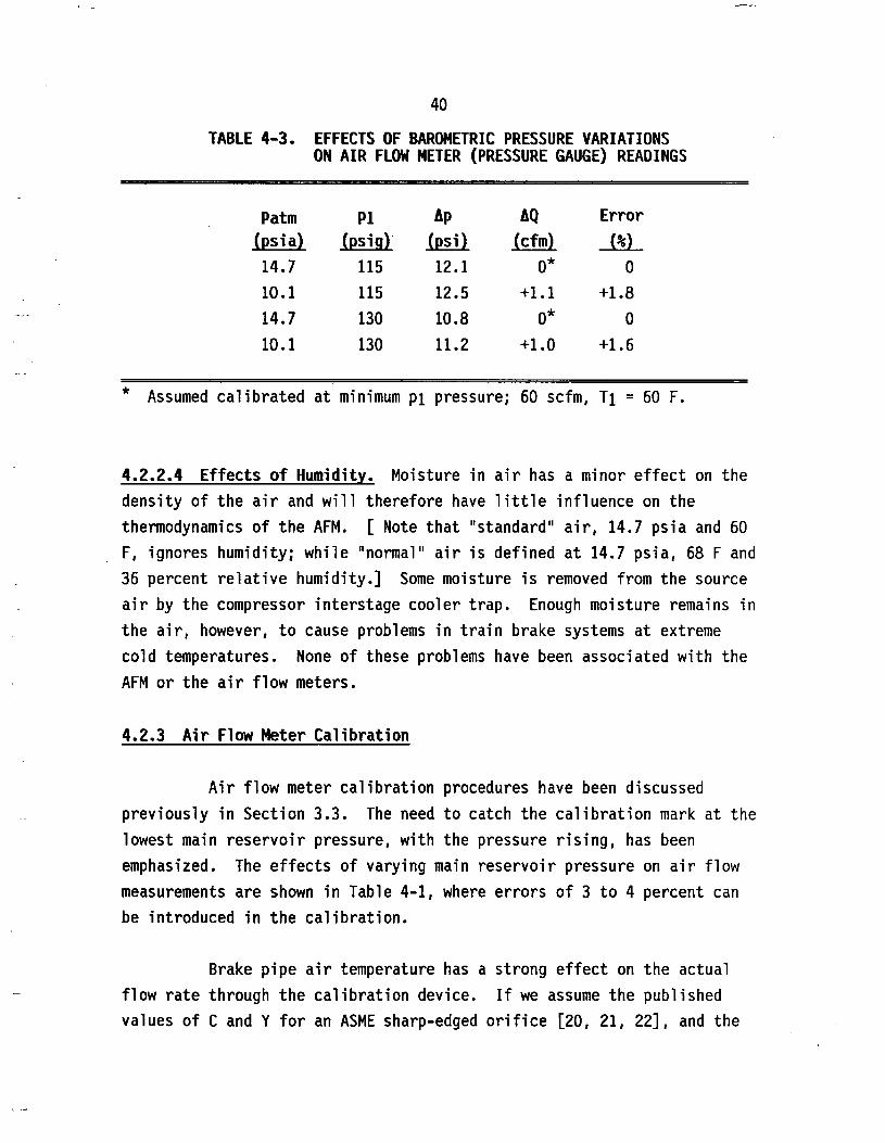
4.2.2.3 Effects of Barometric Pressure. Normal variations in the barometric pressure due to weather conditions range roughly + 1 percent at sea level. The effects of these changes on absolute main reservoir or brake pipe pressures can be ignored. Changes with altitude, however, can
be substantial. At 10,000 ft altitude, a pressure ratio of 0.6877 of
standard atmosphere exists. The effects on air flow measurements with a pressure gauge are given in Table 4-3.
Leakage, however, is also affected by the lower atmospheric pressure. If we assume the same total leakage area at choke flow, and the same brake pipe temperature and pressure (80 psig, for this example), a 60 scfm leak (0.0764 lb/sec) at sea level would decrease to 57.1 scfm (0.0727 lb/sec) at a 10,000-ft elevation.
40
TABLE 4-3. EFFECTS OF BAROMETRIC PRESSURE VARIATIONS ON AIR FLOW METER (PRESSURE GAUGE) READINGS
Patm PI Ap AQ Error
(Psia) (psig) (psi) (cfm) J % L14.7 115 12.1 0* 0
10.1 115 12.5 +1.1 +1.8
14.7 130 10.8 0* 0
10.1 130 11.2 +1.0 +1.6
* Assumed calibrated at minimum pi pressure; 60 scfm, Ti = 60 F.
4.2.2.4 Effects of Humidity. Moisture in air has a minor effect on the density of the air and will therefore have little influence on the thermodynamics of the AFM. [ Note that "standard" air, 14.7 psia and 60 F, ignores humidity; while "normal" air is defined at 14.7 psia, 68 F and 36 percent relative humidity.] Some moisture is removed from the source air by the compressor interstage cooler trap. Enough moisture remains in the air, however, to cause problems in train brake systems at extreme cold temperatures. None of these problems have been associated with the AFM or the air flow meters.
4.2.3 Air Flow Meter Calibration
Air flow meter calibration procedures have been discussed previously in Section 3.3. The need to catch the calibration mark at the lowest main reservoir pressure, with the pressure rising, has been emphasized. The effects of varying main reservoir pressure on air flow measurements are shown in Table 4-1, where errors of 3 to 4 percent can be introduced in the calibration.
Brake pipe air temperature has a strong effect on the actual flow rate through the calibration device. If we assume the published values of C and Y for an ASME sharp-edged orifice [20, 21, 22], and the

41
nominal procedural conditions for calibration on BN and CN, the flow variations can be calculated. These are given in Table 4-4.
TABLE 4-4. EFFECTS OF BRAKE PIPE AIR TEMPERATURE VARIATIONS ON CALIBRATION DEVICE AIR FLOW RATE
Burlington Northern: d0 = 0.234 in. , BP @ 80 psig
Tbp W Q Error
(deg F) (lb/sec) (scfm) J%L-30 .0874 68.6 +9.9
0 .0845 66.3 +6.3
20 .0827 64.9 +4.0
60 .0794 62.4 0
100 .0766 60.1 -3.7
Canadian National*: do = 0.243 in.. BP @ 75 psig
Tbp W Q Error
(deg F) (lb/sec) (scfm)
-30 .0888 69.7 +9.9
0 .0858 67.4 +6.3
20 .0840 66.0 +4.1
60 .0807 63.4 0
100 .0778 61.1 -3.6
* Assuming the Canadian National device is a sharp-edged orifice.
From tests reported by BN, it appears that actual C and Y values are slightly lower than the published values. These air flow calculations are predicated on the 26C control valve maintaining the brake pipe pressure at the desired value: 80 or 75 psig, respectively.
As noted in previous sections, the air flow meter would indicate the same flow, independent of temperature, because of the compensating effect of the orifice and pressure differential gauge. The "calibration", however,would be in error, with actual flow rates proportional to those
42
of Table 4-4. For this reason, the calibration device must be certified (calibrated itself) at a lower temperature, to minimize this reading error in cold weather, when leakage problems can be accentuated. And for this reason, the AAR Calibration Procedure RP-402 (Figure 3-4) requires the device to pass 60 scfm flow at some temperature not exceeding 20 F.
The calibration device must be treated with care, because any dirt or damage (nicks on the orifice edge, etc.) can cause significant
changes to the flow or expansion coefficients and consequent changes in the calibration air flow.
4.3 A i r Flow Meter Accuracy Requirements
The AAR Mechanical Division has issued specifications for air flow meterrs in the Manual of Standards and Recommended Practices, "Air
Flow Indicators, Specification M-980, effective January 1, 1989". Specification M-980 is included as Appendix A of this report. In these specifications, the device must be accurate within + 2 cfm at a flow rate of of 60 cfm (M-980, Section 3.3).
In Section 4.2.2 of this report, flow accuracies of + 1.5 scfm
were calculated, based on typical pressure gauge errors and a flow rate
of 60 scfm. However, flow measurement by pressure differential across an orifice was found dependent on three important factors:
• Main reservoir air pressure, both the minimum setting and the cycle range: 0 to -2 cfm over compressor cycle.
• Main reservoir air temperature: + 2 cfm over a "reasonable" temperature range (30 to 90 F). •
• Altitude: + 1 cfm at 10,000 ft elevation.

43These errors can combine to give total errors ranging from
+4.5 cfm to - 5.5 cfm at a nominal 60 scfm, with an rms (more probable) error of + 2.7 cfm. Therefore the currently-used devices cannot in the strictest sense meet the AAR requirement.
Orifice flow and expansion coefficients, C and Y, tend to increase at lower flow velocities (Reynolds Number) and lower pressure drops, which adds to the basic nonlinearity of the current air flow meters. These errors, however, are dominant only at flows less than
about 5 scfm.
4.4 A ir Flow Meter R e l i a b i l i t y
Currently both the leakage rate test and air flow test methods rely on standard pressure gauges to qualify the train brake system for service. From long service experience, pressure gauges are known for high reliability and endurance. Gauges used in the AFM require the same 92-day inspection cycle as other air pressure gauges in the locomotive cab. The metering orifice at the air flow indicator is a passive device, except for the pressure relief function at high (charging) flow rates. There is no evidence from past experience with the AFM of any problems
with air flow indicators. Therefore, in terms of equipment reliability,
both methods are comparable.
44REFERENCES
1. Federal Railroad Administration, DOT, 49 CFR Ch. II (10-1-87 Edition), Part 232-Railroad Power Brakes and Drawbars, pp. 199-210.
2. D. G. Blaine and M. F. Hengel, "Brake-System Operation and Testing Procedures and Their Effects on Train Performance", ASME Paper No. 71-WA/RT-9, 1971.
3. R. L. Wilson, "Factors Affecting Air Brake Operation", Westinghouse Air Brake Division (undated).
4. R. L. Wilson, "Leakage and Gradient Considerations in Train Braking", Air Brake Association Annual Meeting, Chicago, Illinois, September 28, 1976.
5. J. G. Smith, "The Air Flow Method of Testing Air Brakes", 42nd Annual Proceedings of The Railway Fuel and Operating Officers Association, 1978, pp. 94-111.
6. D. J. Wickham, "Flow/Leakage Relationships in Train Brake Systems", Air Brake Association Annual Meeting, October 1978.
7. B. W. Shute, "The Interrelation of Brake Pipe Leakage, Gradient & Flow", The Air Brake Association Annual Meeting, Chicago, Illinois, September 18, 1979.
8. CN Rail Operations, "The Air Flow Method of Testing Air Brakes", Final Summation to The Railway Transport Committee of The Canadian Transport Commission, February 1981.
9. D. G. Blaine, M. F. Hengel and J. H. Peterson, "Train Brake and Track Capacity Requirements for the '80s", ASME Paper No. 81-RT-ll, April 1981.
10. W. G. Threlfell, "Update of Air Flow Method, CN Rail", 45nd Annual Proceedings of The Railway Fuel and Operating Officers Association, 1981, pp. 26-33.
11. D. J. Manconi, "Air Flow Method of Testing", 50nd Annual Proceedings of The Railway Fuel and Operating Officers Association, 1986, pp. 197-209.
12. A. H. Fiedler and R. D. Fry, "The Air Flow Method", 47nd Annual Proceedings of The Railway Fuel and Operating Officers Association, 1983, pp. 101-113.
13. E. K. Bender, L. E. Wittig and J. D. Stahr, "Freight Train Brake System Safety Study", Final Report, Bolt Beranek and Newman, Inc., D0T/FRA/0RD-83/18, August 1983.

45
REFERENCES (CONT.)
14. M. R. Johnson, "Freight Train Brake System Safety Study", Final Report, IIT Research Institute, D0T/FRA/0R&D-84/16, November 1984.
15. M. R. Johnson, "Factors Affecting the Development of Transient Buff and Draft Forces During Freight Train Braking", ASME Paper No. 83- WA-RT-10, November 1983.
16. M. R. Johnson, G. F. Booth and D. W. Mattoon, "Development of Practical Techniques for the Simulation of Train Air Brake Operation", ASME Paper No. 86-WA/RT-4, November 1986.
17. K. S. Abdol-Hamid, D. E. Limbert, R. G. Gauthier, G. A. Chapman andL. E. Vaughn, "Simulation of a Freight Train Air Brake System", ASME Paper No. 86-WA/RT-15, November 1986.
18. K. Abdol-Hamid, D. E. Limbert and G. A. Chapman, "The Effect of Leakage on Railroad Brake Pipe Steady State Behavior", Trans. ASME, Journal of Dynamic Systems, Measurement and Control, September 1988, Vol. 110, pp.329-335.
19. F. G. Carlson, Jr., and D. G. Blaine, "The AAR Undesired Emergency Study", ASME Paper No. 86-WA/RT-19, November 1986.
20. E. A. Avallone, T. Baumeister III, Ed., Marks1 Standard Handbook for Mechanical Engineers, Ninth Edition, McGraw-Hill Book Company, 1987, pp. 3-62 to 3-66, 4-22 to 4-24.
21. V. L. Streeter, Fluid Mechanics, Fifth Edition, McGraw-Hill Book Company, 1971, pp. 466-473.
22. Crane Co., Flow of Fluids Through Valves, Fittings, and Pipes, Technical Paper No. 410, 1969.
23. H. S. Bean, Ed., Fluid Meters - Their Theory and Application, ASME, Sixth Edition, 1971, pp. 66-67.

APPENDIX A
AAR SPECIFICATION M-980

A-l
Association of American Railroads Mechanical DivisionManual of Standards and Recommended Practices u.9soAIR FLOW INDICATORS SPECIFICATION M-980 Effective January 1,1989
1.0 PURPOSEThe purpose of this specification is to define minimum functional, mechanical, test and approval requirements for Air Flow Method (AFM) type flow indicators. This indicator is for use on a locomotive equipped with a 19/64' orifice per RP-505, Section F, Manual of Standards and Recommended Practices.
2.0 SCOPEAll AFM type flow indicators used on locomotives must meet the requirements of these specifications and shall be subject to approval by the Mechanical Division, Association of American Railroads, for design, method of application, operation, testing and approval.The manufacturer will apply in writing to the Director Technical Committees: Quality Assurance, Mechanical Division, Association of American Railroads, Washington, D.C., to initiate the approval process.
2.2The request for approval must include fifteen (15) sets of drawings showing the assembled flow indicator device, sectional views with component parts numbered and a parts list showing the piece number, reference and description of the component parts. In addition, fifteen (15) copies of manufacturer’s recommended test code and shop maintenance instructions for the flow indicator device on which approval is desired are to be submitted.A representative of the AAR will select six (6) flow indicator devices for test purposes from e production lot of not less than fifty (50) devices of the design being submitted for approval. Two (2) devices will be tested in accordance with Sections 3.0 and 4.0. Two (2) devices will be tested in accordance with Section 5.0. Two (2) devices will be tested in accordance with Section 6.0.The manufacturer must submit in writing a request to change or modify the design, material, manufacture of parts, location of manufacture or assembly of conditional or approved flow indicator device or related equipment. Changes cannot under any circumstances be introduced into production before the AAR Brake Equipment Committee has approved the change and the manufacturer advised of approval by the AAR.
2.5All replacement parts used in flow indicator device maintenance must be equal to or better than original equipment material and, where possible, include the manufacturer’s identification.
10/108 E-483

A-2
Association of American Railroads Mechanical Divisionm-»8o Manual of Standards and Recommended Practices2.6
Following AAR Brake Equipment Committee conditional approval, the manufacturer is required to furnish semi-annually a report of distribution and service performance, which is due within thirty (30) days of the January 1 and July 1 reporting dates. The distribution portion must include the total distribution at the end of the reporting period. The service performance portion must include all known malfunctions or difficulties experienced. This report must be submitted until unconditional approval is granted.2.7
In the event the foregoing is not complied with, the AAR Brake Equipment Committee will consider withdrawal of approval.3.0 REQUIREMENTS3.1
The device must be clearly identified as an air flow indicator or AFM indicator. The manufacturer’s name and a unique serial number must be clearly marked on each device so it can be read when indicator is installed.3.2
The device must be capable of in-place adjustment for calibration purposes but so designed to discourage tampering.3.3
The device must be accurate within ±2 cfm at a flow rate of 60 cfm.3.4
The device must be capable of withstanding 300 psig proof pressure and differential pressure rating up to 40 psig.3.5
The device sensitivity must be capable of indicating a ±2 cfm change in flow at the 60 cfm level. The device must respond to 1/2 psi changes in differential pressure.3.6
The device may be of the pneumatic or electronic type. It must be easily readable day or night, illuminated as required, producing minimum glare.3.7
The device may be equipped with indicator lights or warning buzzer, with reset feature, for special functions.3.8
The device must indicate flow in units of cfm, and be designed and calibrated so that the pointer or reading indicating a flow of 60 cfm be located near the center of the scale. Gauge face must display markings from 10 cfm to 80 cfm, in 10 cfm or less increments, with numerals indicating 20,40, 60 and 80 cfm markings for continuous monitoring of flow. The gauge scale, from bottom marking to top marking, must cover a linear length of at least 3 inches. (Digital air flow indicator must display flow continuously from 10 cfm to 80 cfm in 1 cfm increments.)
E-484 10/1/88

A-4
Association of American Railroads Mechanical Division•*■980 Manual of Standards and Recommended Practices6.0 VIBRATION AND SHOCK TESTS6.1
Subject device to a sinusoidal vibration input of 2G. The frequency is to be varied at a rate of one octave per minute from 10 Hz to 200 Hz and then back from 200 Hz to 10 Hz. The device shall be vibrated in each of the three major axes. An accelerometer will be mounted on the device to detect natural frequencies. The device shall be vibrated continuously at the frequency with the highest feedback for a period of one hour with a 2G input load. Subject device to vertical and lateral shock of 2G peak for 0.01 second and longitudinal shock of 6G peak for 0.01 second.At completion of vibration and shock tests, the device shall be recalibrated and tested per paragraphs 3.3 through 3.5 to ensure that the device is operational.

^ S E A R r S n S I T Q W^ C H & D ^ E l o p m N t
Evaluation of Locomotive CAB Air Flow Meters for Train Air Brake Leakage Monitoring, 1989 DR Ahibeck, SM Kiger