draft pre-decisional draft waste heat recovery …
TRANSCRIPT

DRAFT – PRE-DECISIONAL – DRAFT
1
Waste Heat Recovery 1
Technology Assessment 2
Contents 3
1. Introduction to the Technology/System ............................................................................................... 2 4
1.1. Introduction to Waste Heat Recovery .......................................................................................... 2 5
1.2. Challenges and Barriers for Waste Heat Recovery ..................................................................... 13 6
1.3. Public and Private Activities ........................................................................................................ 15 7
1.4. Public/Private Roles Going Forward ........................................................................................... 15 8
2. Technology Assessment and Potential ............................................................................................... 15 9
2.1. Current Status of Waste Heat Recovery Technologies ............................................................... 15 10
2.1.1. Commonly Used Waste Heat Recovery Systems ................................................................ 15 11
2.1.2. Emerging or Developing Waste Heat Recovery Technologies ............................................ 16 12
2.1.3. Limitations of Currently Available Technologies................................................................. 18 13
2.2. R&D Opportunities ...................................................................................................................... 19 14
2.2.1. R&D Opportunities for Various Temperature Ranges ........................................................ 19 15
2.2.2. R&D Opportunities by Major Industry ................................................................................ 21 16
2.2.3. R&D Opportunities by Research Category .......................................................................... 23 17
3. Risk and Uncertainty, and other Considerations ................................................................................ 26 18
4. Sidebars; Case Studies ........................................................................................................................ 26 19
5. References .......................................................................................................................................... 26 20
21
22

DRAFT – PRE-DECISIONAL – DRAFT
2
1. Introduction to the Technology/System 23 1.1. Introduction to Waste Heat Recovery 24
Waste heat in manufacturing is generated from several industrial systems distributed throughout 25 a plant. The largest sources of waste heat for most industries are exhaust and flue gases and 26 heated air from heating systems such as high-temperature gases from burners in process 27 heating; lower temperature gases from heat treating furnaces, dryers, and heaters; and heat 28 from heat exchangers, cooling liquids, and gases. While waste heat in the form of exhaust 29 gases is readily recognized, waste heat can also be found within liquids and solids. Waste heat 30 within liquids includes cooling water, heated wash water, and blow-down water. Solids can be 31 hot products that are discharged after processing or after reactions are complete, or they can be 32 hot by-products from processes or combustion of solid materials. Other waste heat sources are 33 not as apparent such as hot surfaces, steam leaks, and boiler blow-down water. Table 1 shows 34 typical major waste heat sources along with the temperature range and characteristics of the 35 source [1]. 36
37 Table 1: Temperature Range and Characteristics for Industrial Waste Heat Sources [1] 38
Waste Heat Source Temperature Range Cleanliness
Furnace or heating system exhaust gases 600 – 2,000 Varies
Gas (combustion) turbine exhaust gases 900 – 1,100 Clean
Reciprocating engines
Jacket cooling water 190 – 200 Clean
Exhaust gases (for gas fuels) 900 – 1,100 Mostly clean
Hot surfaces 150 – 600 Clean
Compressor after-inter cooler water 100 – 180 Clean
Hot products 200 – 2,500 Mostly clean
Steam vents or leaks 250 – 600 Mostly clean
Condensate 150 – 500 Clean
Emission control devices – thermal oxidizers, etc. 150 – 1,500 Mostly clean
39 A number of reports prepared for the Department of Energy (DOE) and other organizations ([2], 40 [3], [4], [7], [8], and [9]) studied sources of waste heat, primarily from industrial heating systems. 41 The scope of these reports varied from estimating losses from various industrial heating 42 systems in Btu per year to reviewing waste heat from various industries and identifying general 43 R&D opportunities. Following is an overview of several waste heat reports that were used as 44 references in this technology assessment. 45 46 Energy Use and Loss Analysis [2] 47 The “Energy Use and Loss Analysis” report [2], prepared by Energetics Incorporated, describes 48 total energy used by major manufacturing sectors identified by North American Industry 49 Classification System (NAICS) codes, using Manufacturing Energy Consumption Survey 50 (MECS) data published by the Energy Information Agency. The MECS data was used to 51 estimate major areas of energy use in a plant as well as losses from the subsystems, as shown 52 in Figure 1. 53 The losses were based on estimated percentages of losses for the major areas of energy use. 54 The loss factors for each area are shown in Table 2. Based on the loss factors and energy use, 55 an estimate was made for the energy losses in various industrial sectors, as seen in Figure 2. 56 The report did not attempt to identify specific areas of waste heat for the energy systems. 57 58
Figure 1: Major Areas of Energy Use in a Manufacturing Plant [2] 59

DRAFT – PRE-DECISIONAL – DRAFT
3
60
61 62
63 64 65 66 67
68 69 70 71 72
73 74
75
76 Table 2: Energy Loss Factors for Major Energy Systems in a Manufacturing Plant [2] 77
Energy System Percent Energy Lost
Steam systems Boilers – 20% Steam pipes and traps - 20% Steam delivery/heat exchangers – 15%
Power generation Combined heat and power – 24% (4500 Btu/kWh) Conventional power – 45% (6200 Btu/kWh)
Energy distribution Fuel and electricity distribution lines and pipes (not steam) – 3%
Energy conversion
Process heaters – 15% Cooling systems – 10% Onsite transport systems – 50% Electrolytic cells – 15% Other – 10%
Motor systems
Pumps – 40% Fans – 40% Compressed air – 80% Refrigeration – 5% Materials handling – 5% Materials processing – 90% Motor windings – 5%
78
Energy
SupplyCentral
Energy
Generation/
Utilities
Energy
Distribution
Energy
Export
Energy
Losses
Energy Recycle
Industrial Plant Boundary
Utility/
Power
Plant
Energy
Conversion
Process
Energy
Use
Process Energy Systems
Fossil
Energy
Supply
Plant Operation/System
Process Energy System
Facilities/HVAC/ Lighting
Inside Plant Boundary
Energy
Losses TBD
Solar/Geo-
thermal/Wind
Energy
Energy
SupplyCentral
Energy
Generation/
Utilities
Energy
Distribution
Energy
Export
Energy
Losses
Energy Recycle
Industrial Plant Boundary
Utility/
Power
Plant
Energy
Conversion
Process
Energy
Use
Process Energy Systems
Fossil
Energy
Supply
Plant Operation/System
Process Energy System
Facilities/HVAC/ Lighting
Inside Plant Boundary
Energy
Losses TBD
Solar/Geo-
thermal/Wind
Energy

DRAFT – PRE-DECISIONAL – DRAFT
4
Figure 2: Estimates of Energy Losses for Major Energy Use Areas in Manufacturing [2] 79
80 81 82 83
84 85 86 87 88
89 90
91 92 93 94
Waste Heat Recovery: Technology and Opportunities in U.S. Industry [3] 95 AMO issued a detailed report prepared by BCS Incorporated titled “Waste Heat Recovery: 96 Technology and Opportunities in U.S. Industry” that provides information on waste heat sources 97 in major industrial sectors; the nature of waste heat; available waste heat recovery equipment 98 currently used by the industry; and research, development, and demonstration (RD&D) needs. 99 The report classifies waste heat sources in three categories: high temperature (>1,200°F), 100 medium temperature (450°–1,200°F), and low temperature (<450°F). 101 The BCS report provides a waste heat profile that describes the type of waste heat discharged 102 from industrial plants, general observations related to waste heat sources, the nature of waste 103 heat, and waste heat recovery practices. It outlines RD&D opportunities to extend the economic 104 operating range of conventional technologies and conduct RD&D in emerging and novel 105 technologies. 106 The report also identifies uncovered waste heat in different temperature ranges, concluding that 107 the amount of heat wasted above 77°F reference temperature is 1,478 trillion Btu per year and 108 lowers to 256 trillion Btu per year if the reference temperature is raised to 300°F. This indicates 109 significant heat recovery opportunities in the 77°–300°F temperature range, which represents 110 more than 80% of the total estimated waste heat and emphasizes the need for R&D in this 111 range. 112 A summary of key RD&D opportunities identified in the BCS report cross-walked against 113 barriers these opportunities address are shown in Table 3 [3]. 114 115
To Processes
Generation Losses
Distribution Losses
Conversion Losses
0 1000 2000 3000 4000 5000 6000 7000
Facilities
Steam Systems
Fired Heaters &
Cooling
Motor Systems
Electrochemical
Other
683
TBtu
2336
TBtu 7279
TBtu
6201 TBtu1405
TBtu
Trillion Btu
362
TBtu
*Onsite generated power has been distributed among end-uses and is not included in the total.
Potential Process Losses
To Processes
Generation Losses
Distribution Losses
Conversion Losses
To Processes
Generation Losses
Distribution Losses
Conversion Losses
0 1000 2000 3000 4000 5000 6000 7000
Facilities
Steam Systems
Fired Heaters &
Cooling
Motor Systems
Electrochemical
Other
683
TBtu
2336
TBtu 7279
TBtu
6201 TBtu1405
TBtu
Trillion Btu
362
TBtu
*Onsite generated power has been distributed among end-uses and is not included in the total.
Potential Process Losses

DRAFT – PRE-DECISIONAL – DRAFT
5
Table 3: RD&D Opportunities and Barriers Addressed [3] 116 Barriers Addressed
L
on
g P
ayba
ck P
erio
ds
Ma
teria
l C
on
str
ain
ts
an
d C
osts
Ma
inte
nan
ce
Co
sts
Eco
nom
ies o
f S
cale
La
ck o
f E
nd
-Use
He
at
Tra
nsfe
r R
ate
s
En
vir
on
men
tal
Co
nce
rns
Pro
cess C
on
tro
l a
nd
Pro
du
ct
Qu
alit
y
Pro
cess-S
pe
cific
Co
nstr
ain
ts
Ina
ccessib
ility
Develop low-cost, novel materials for resistance to corrosive contaminants and to high temperatures
x x
Economically scale down heat recovery equipment
x x x
Develop economic recovery systems that can be easily cleaned after exposure to gases with high chemical activity
x x x
Develop novel manufacturing processes that avoid introducing contaminants into off-gases in energy-intensive manufacturing processes
x x x x x
Develop low-cost dry gas cleaning systems
x x x x x
Develop and demonstrate low-temperature heat recovery technologies, including heat pumps and low-temperature electricity generation
x x
Develop alternative end-uses for waste heat
x
Develop novel heat exchanger designs with increased heat transfer coefficients
x x x
Develop process-specific heat recovery technologies
x x x x x x
Reduce the technical challenges and costs of process-specific feed preheating systems
x x x x x
Evaluate and develop opportunities for recovery from unconventional waste heat sources (e.g., sidewall losses)
x x
Promote new heat recovery technologies such as solid-state generation
x
Promote low-cost manufacturing techniques for the technologies described above
x x x x x x x x x x
117 This study investigated several industrial processes, consuming a total of ~8,400 TBtu/yr, in 118 order to estimate waste heat recovery opportunities. Estimates of unrecovered waste heat are 119 shown in Figure 3 and 4. The Figure 4 indicates that the majority of waste heat losses (based 120 on a 77°F [25°C] reference) are in the low temperature range. Though low temperature waste 121 heat is a lower quality heat source, it is present in sufficiently large magnitudes that its work 122 potential exceeds that of other waste heat sources. 123

DRAFT – PRE-DECISIONAL – DRAFT
6
Figure 3: Waste heat losses and work potential from selected process exhaust gases [3] 124 125
NOTE: Steam boilers are divided into conventional fuels (CF) and byproduct fuels (BF). It is important to note that 126 while steam boilers have higher waste heat losses; this is due to the large number of industrial boilers (about 43,000 127 total units) rather than due to boiler inefficiency. Typical boiler efficiencies (80-85%) are much higher than other fired 128 units such as glass furnaces. Heat losses from boilers are in the low temperature range, as evidenced by the low 129 heat content from a 300°F [150°C] reference. *Also note that values reported above do not reflect total waste heat 130 losses by industry, but rather the waste heat losses from selected processes. Iron/Steel includes coke ovens, blast 131 furnaces, basic oxygen furnaces, and electric arc furnaces. Aluminum includes primary refining cells and secondary 132 melting furnaces. Metal casting melting includes aluminum reverberatory furnaces, stack melters, and iron cupolas in 133 metal casting facilities. Aluminum includes primary and secondary refining furnaces. 134 135
Figure 4: Unrecovered waste heat in different temperature groups [3] 136 137 138 139
140 141
142 143
144 145 146 147
148 149 150
151 152 153 154 Note: Figure 4 displays estimated waste heat losses in different temperature groups. The temperature groups are 155 defined as: High – 1200°F [650°C] and higher; Medium - 450°F [230°C] to 1,200°F [650°C]; and Low - 450°F [230°C] 156 and lower. 157
DRAFT – PRE-DECISIONAL – DRAFT
7
Opportunity Analysis for Recovering Energy from Industrial Waste Heat and 158
Emissions [4] 159 A Pacific Northwest National Laboratory (PNNL) report titled “Opportunity Analysis for 160 Recovering Energy from Industrial Waste Heat and Emissions” discusses waste energy 161 availability [4]. The report analyzes barriers and pathways to recovering chemical and thermal 162 emissions from U.S. industry, with the goal of more effectively capitalizing on such oppor-163 tunities. 164 A primary part of this study was characterizing the quantity and energy value of these 165 emissions. The authors surveyed publicly available literature to determine the amount of energy 166 embedded in the emissions and identify technology opportunities to capture and reuse this 167 energy. The authors identify U.S. industry as having 2,180 petajoules (PJ), or 2 Quads 168 (quadrillion Btu), of residual chemical fuel value. As landfills are not traditionally considered 169 industrial organizations, the industry component of these emissions has a value of 1,480 PJ, or 170 1.4 Quads—approximately 4.3% of total energy use by U.S. industry. 171 The report discusses the advanced materials (e.g., thermoelectric, thermionic, and 172 piezoelectric) and other technologies (e.g., solid oxide fuel cells) that, in the authors’ opinion, 173 are the most promising technologies for re-utilizing chemical and thermal emissions. The 174 authors recommend additional research and development as well as industry education to make 175 these technologies sufficiently cost effective and widely commercialized. 176 177 Engineering Scoping Study of Thermoelectric Generator (TEG) Systems for 178 Industrial Waste Heat Recovery [5] 179 PNNL and BCS, Incorporated prepared a report titled “Engineering Scoping Study of 180 Thermoelectric Generator (TEG) Systems for Industrial Waste Heat Recovery” that was issued 181 in November 2006 [5]. This report evaluated the TEG system with the intent to accomplish the 182 following: 183
Examine industrial processes in order to identify and quantify industrial waste heat 184 sources that could potentially use TEGs. 185
Describe the operating environment that a TEG would encounter in selected industrial 186 processes and quantify the anticipated TEG system performance. 187
Identify cost, design, and engineering performance requirements needed for TEGs to 188 operate in the selected industrial processes. 189
Identify the research, development, and deployment needed to overcome limitations that 190 discourage the development and use of TEGs for recovery of industrial waste heat. 191
Three industrial waste heat processes were selected to investigate applicability of TEGs: glass 192 furnaces (485°–1,400°C), aluminum Hall-Hèroult cells (~960°C), and reverberatory furnaces 193 (~760°C). Based on the analysis of opportunities, the report concludes that TEG application in 194 glass furnaces would generate more than $25 million in annual sales, assuming that higher 195 efficiency TEGs with a dimensionless figure of merit ZT ~2 could be built for $5/watt and 196 assuming that 5% of the market buys TEGs per year. 197 The report suggests pursuing R&D work in thermal transfer technologies and engineering 198 studies to interface TEG systems with existing process equipment, as well as studies of 199 possible exhaust system modifications (e.g., duct length and residence times) that could lead to 200 greater opportunities for integrating TEG systems in more industrial applications. 201 Analysis of waste heat sources and recovery is greatly affected by the waste heat 202 temperature—therefore it is necessary to clearly identify the temperature regimes for waste heat 203 related discussions. The BCS report identifies three temperature ranges to classify waste heat 204 sources and opportunities; however, there is no general agreement on or basis for this definition 205 of the temperature range. In this report, the temperature ranges have been expanded on both 206 sides (high and low) of the spectrum. This expansion allows for the exploration and identification 207

DRAFT – PRE-DECISIONAL – DRAFT
8
of R&D opportunities in the temperature ranges below 250°F (ultra-low temperature) and higher 208 than 1,600°F (ultra-high temperature), in which it is difficult to identify cost-effective waste heat 209 recovery methods or equipment. Hence, this report recognizes the following five temperature 210 ranges: 211
Ultra low temperature: below 250°F. The lower temperature for this range is usually the 212 ambient temperature or the temperature of a cooling medium such as cooling tower 213 water or other water used for cooling systems. The upper limit is based on several 214 considerations, such as the condensation temperature of combustion products or flue 215 gases (usually below 180°F for natural gas combustion products); the applicability of 216 low-temperature, non-oxidizing materials such as aluminum or non-metallic materials 217 such as polymers or plastics; or the usage of low-temperature waste heat recovery 218 systems such as heat pumps. 219
Low temperature: 250°–450°F, as defined in the BCS report. 220 Medium temperature: 450°–1,200°F, as defined in the BCS report. 221 High temperature: >1,200°F, as defined in the BCS report. However, based on contacts 222
with the industry and waste heat recovery equipment suppliers, it is suggested that this 223 range be divided in two temperature ranges. The normal definition of the “high” 224 temperature range, based on availability of equipment and material, is 1,200°–1,600°F. 225
Ultra high temperature: >1,600°F. Waste heat recovery from streams above 1,600°F 226 requires use of special high-temperature materials that can be metallic or nonmetallic, 227 such as ceramics. Selection of material and equipment design becomes very critical in 228 many cases, as such streams contain a large amount of contaminants. 229
230
Technologies and Materials for Recovering Waste Heat in Harsh Environments [6] 231 The temperature of the exhaust gases discharged into the atmosphere from heating equipment 232 depends on the process temperature and whether a waste heat recovery (WHR) system is used 233 to reduce the exhaust gas temperature. The temperature of discharged gases varies from as 234 low as 150°F to as high as 3,000°F. Combustion products themselves, generated from well-235 designed and well-operated burners using gaseous and light liquid fuels, are relatively clean 236 and do not contain particles or condensable components that may require “cleanup” before 237 discharge into the atmosphere. However, during the heating process, the combustion products 238 may react or mix with the product being heated and may pick up constituents such as reactive 239 gases, liquid vapors, volatiles from low-melting-temperature solid materials, particulates, 240 condensable materials, and the like. Some or all of these constituents, particularly at high 241 temperatures, may react with materials used in the construction of downstream heat WHR 242 equipment and create significant problems. Potential issues include chemical reaction of 243 exhaust gases and their solid or vapor content with the materials used in the WHR equipment; 244 deposit of particulates in or on surfaces of WHR equipment; condensation of organics such as 245 tars and inorganic vapors such as zinc oxides and boron on heat exchanger surfaces; and 246 erosion of heat exchanger components by the solids in the exhaust gases. Many of these 247 problems are compounded by the high temperature of the exhaust gases, uneven flow patterns 248 of the hot gases inside the heat exchanger, and operating variations such as frequent heating 249 and cooling of the heat exchanger. The report prepared by Oak Ridge National Laboratory and 250 E3M Inc. identifies industries and industrial heating processes in which the exhaust gases are at 251 high temperature (>1200°F), contain all of the types of reactive constituents described, and can 252 be considered as harsh or contaminated. The report also identifies specific issues related to 253 WHR for each of these processes or waste heat streams. 254 255 The following are common characteristics of the gases classified as harsh environments: 256
DRAFT – PRE-DECISIONAL – DRAFT
9
1. High gas temperature (>1,600F): Although the process temperature might be less than 257 1,600°F, the presence of combustible components such as CO, H2, or hydrocarbons in 258 flue gases, and their combustion in the presence of air that could leak into the flue gas 259 ducts or into a WHR system such as a recuperator, could increase the localized 260 temperature that may exceed temperature limit of the heat recovery system component 261 temperature. Examples include EAF and BOF exhaust gases and flue gases from “over-262 fired” aluminum melting furnaces. 263
2. Presence of highly corrosive fluxing agents (e.g., salts, calcium, chlorides, fluorides): 264 The types and amounts of fluxing agents or their compounds depend on the heating 265 process and the final product specifications. These fluxing agents introduce highly 266 corrosive elements that promote degradation of materials in WHR equipment. For 267 example, chemical reactions between the corrosive gases and metal tubes in a 268 recuperator could result in an extremely short life for the recuperator. The use of 269 advanced or exotic materials that would extend the recuperator life is uneconomical for 270 most applications. 271
3. Presence of particulates (e.g., metal oxides, carbon or soot particles, fluxing materials, 272 slag, aluminum oxide, magnesium oxide, manganese): Fine particles entrained in flue 273 gases may react with the heat exchanger materials (metallic or nonmetallic), resulting in 274 reduction of heat transfer and in damaging reactions with heat exchanger materials. The 275 net effect of these reactions is a shorter life for recuperator parts and, often, premature 276 failure of metals at critical locations. In some cases, such as in boilers, it is possible to 277 remove the material buildup by soot blowing, but this is not possible for all types of heat 278 recovery systems. 279
4. Presence of combustibles (e.g., CO, H2, hydrocarbons): The presence of combustibles 280 in flue gases could result in higher-than-design temperatures for heat exchangers owing 281 to air leaks or the addition of dilution or cooling air to flue gases. In cases where no 282 cooling or dilution air is used, the presence of combustibles still presents severe 283 problems. The combustibles may react with constituents (such as nickel) of high-284 temperature alloys to form soot that deposits on heat transfer surfaces and reacts with 285 metal leading to shortened life of equipment components. 286
5. Presence of combustible volatiles from charge material such as scrap used for aluminum 287 melting furnaces and EAF: The scrap is obtained from a variety of sources and the 288 plants use separation processing of scrap to remove combustible materials such as oils, 289 paint, paper, plastic, and rubber. However, some of these materials end up in the charge 290 material. Incomplete combustion, or breakdown of these organic materials results in the 291 presence of combustible gases or solids, and they have the same effects on heat 292 recovery equipment as the combustible materials described in item 4. 293
6. Variations in flow, temperature and composition of gases: Most heating equipment using 294 a large amount of energy, such as EAFs, BOFs, and many aluminum melting furnaces, 295 operates in a batch or semi-continuous mode. This results in variations in temperature, 296 flow, and the composition of flue gases leaving the furnace. Variations in flue gases 297 could result in cycling of materials (metal, in the case of a recuperator) and thermal 298 fatigue of metals used in the heat recovery equipment. Thermal fatigue reduces the life 299 of materials. 300
301 At this time the industry uses several practices for managing or dealing with exhaust gases 302 classified as harsh environments: 303
1. No heat recovery but treating (scrubbing, cooling by blending with cold air or mist 304 cooling) exhaust gases to meet regulatory requirements. Examples are EAF and BOF 305 exhaust gases. 306

DRAFT – PRE-DECISIONAL – DRAFT
10
2. Partial WHR due to materials limitations, design issues and space considerations. An 307 example is preheating of glass melting furnace combustion air using regenerators. 308
3. Partial heat recovery due to other limitations such as safety, maintenance, lifetime. 309 Examples are use of scrap preheaters for EAFs and use of steam generation for BOF 310 installations. 311
4. Partial or no heat recovery due to high capital cost, limited operating hours, or other 312 operating and economic reasons. Examples are small glass and aluminum melting 313 furnaces and cement and lime kilns. 314
5. Loss of sensible heat and loss of certain condensable organic materials (e.g., tar, 315 condensable liquids, volatiles) during treatment of exhaust gases, and use of chemical 316 heat after drying the gases as fuels. Examples are blast furnaces and coke ovens. 317
318 Table 4 summarizes information about the waste heat in exhaust gases identified as harsh 319 environments resulting from selected processes in those industries. 320 Calculations were performed for recoverable waste heat from harsh environment gases for each 321 of these industrial sectors. The calculations were based on available information from various 322 sources identified in the report. The results from the calculations are also provided in Table 4. 323 324

DRAFT – PRE-DECISIONAL – DRAFT
11
Table 4 - Recoverable waste heat from selected harsh environment waste gas streams [6] 325 Criteria: Exhaust gases considered either >650C and/or containing combustibles and contaminants
Industry Waste heat source Temp. range (°C)
Characteristics WHR
technology/system status
Production (MM
tons/year)
Recoverable—potential TBtu/year
a Exhaust gas
flow
Sensible Chemical Total
Steel
Blast furnace gases 400 to 600
Contain combustibles, particulates, etc.
Available and widely used–partial WHR
30 15.49 172.69 188.2 Constant
EAF exhaust gases 1,500 to 1,600
Contain combustibles, particulates, etc.
Available, not widely used–partial WHR
64.32 27.21 34.86 62.1 Varying
Basic oxygen process 1,250 to 1,700
Contain combustibles, particulates, etc.
Available, not widely used–partial WHR
31.68 4.47 25.22 29.7 Varying
Glass
Flat glass 430 to 1430
Contain particulates, etc. Available for air-fuel combustion only and widely used–partial WHR
5.00 12.38 Negligible 12.4 Constant
Container glass 430 to 1430
Contain particulates, condensable vapors, etc.
Available for air-fuel combustion only and widely used–partial WHR
10.00 19.30 Negligible 19.3 Constant
Glass fiber (all types) 980 to 1430
Contain particulates, condensable vapors, etc.
Available for air-fuel combustion only and partially used–partial WHR
3.00 3.65 Negligible 3.7 Constant
Specialty glass 480 to 1430
Contain particulates, condensable vapors, etc.
Available for partial heat recovery but rarely used.
2.00 7.60 Negligible 7.6 Constant
Aluminum
Al melting furnaces 750 to 950
Contain combustibles, particulates, etc.
Available, not widely used–partial WHR
10.00 15.88 Small - site
specific 15.9 Constant
(fuel fired)
Anode baking 300 to 500
Contain combustibles, particulates, polycyclic organic matter, etc.
Available but NOT demonstrated
2.22 1.88 Small/site specific
(unknown) 1.9 Constant
Calcining 300 to 500
Particulates, fuel combustion products, etc.
Available but NOT demonstrated
Data not available at this time
Cement (Clinker)
Cement kiln exhaust gases from modern clinker making operation
200 to 400
Contain particulates, etc. Relatively easy to handle
Available, not widely used–partial WHR
69.3 53.02 Negligible 53.0 Constant
Lime
Lime kiln exhaust gases based on commonly used rotary kiln type operation
200 to 600
Contain particulates, etc. Relatively easy to handle
Available, not widely used–partial WHR
20.9 40.7 Negligible 40.7 Constant
Total 434.4 a For few waste heat sources (particularly in steel, aluminum, and glass industry), a small quantity of waste heat is already being recovered using the existing WHR technologies. 326

DRAFT – PRE-DECISIONAL – DRAFT
12
Other Reports 327 The Lawrence Berkeley National Laboratory Industrial Energy Study group has prepared 328 several reports ([7] and [8]) that describe energy use and energy efficiency improvement 329 opportunities such as the “Energy Efficiency Improvement and Cost Savings Opportunities for 330 Petroleum Refineries: An ENERGY STAR Guide for Energy and Plant Managers.” These 331 reports were published for several industries, including steel, cement, and food processing, and 332 include discussion of waste heat recovery and suggestions on using certain technologies to 333 recover waste energy for industrial processes. 334 A July 2009 report prepared by McKinsey & Company [9], “Unlocking Energy Efficiency in the 335 U.S. Economy,” examines, in detail, the potential for greater efficiency in non-transportation 336 energy uses and assesses the barriers to this goal. The report suggests formulating an 337 overarching strategy that includes recognizing energy efficiency as an important energy 338 resource, as well as formulating and launching approaches to foster innovation in the 339 development and deployment of next-generation energy efficiency technologies. The report 340 does not provide specific suggestions regarding R&D program areas. 341 In September 2009, an industry-government forum on Energy Intensive Processes was held at 342 the ITP-sponsored “Energy Intensive Processes Workshop.” The goal of the workshop was to 343 collect feedback on ITP’s Energy-Intensive Processes R&D portfolio and strategy, as well as 344 obtain guidance on future efforts. The workshop included a session on waste heat minimization 345 and recovery and discussion on reducing fuel demands of steam boilers and furnaces by 346 utilizing waste heat recovery. Workshop participants were asked to evaluate platforms, R&D 347 focus areas, and project selections, and to provide recommendations on future topic areas. 348 Participants were interested in the following areas of waste heat minimization and recovery: 349
Ultra-high efficiency steam generation, with one project including the “super boiler” 350 High-efficiency process heating equipment, with priority R&D opportunities including the 351
following: 352 o Ultra-high efficiency combustion 353 o Insulation and refractory systems 354
Waste energy recovery, with top R&D opportunities including the following: 355 o Low-temperature heat utilization 356 o Advanced energy conversion (e.g., solid-state and mechanical) 357 o Heat recovery from high-temperature contaminated flue gases 358 o Deployment of novel, waste-heat-to-electricity in a series of industrial 359
demonstrations 360 Waste energy minimization, with top R&D opportunities including the following: 361
o Develop high-efficiency compressors, motors, and variable speed drives 362 o Implement heat transfer improvements, such as coatings, and other ways to 363
resist corrosion 364 Process intensification and integration, with top R&D opportunities including the 365
following: 366 o Integrate industrial control system components (e.g., valves, actuators, and 367
sensors) 368 o Replace batch operations with continuous ones 369 o Develop predictive modeling and simulation for combustion 370
371 Findings from Previous Reports 372 Analysis of previous studies along with direct contact with industry and equipment suppliers 373 have shown that a large amount of waste heat is not recovered in two temperature ranges: 374 ultra-low (<250°F) and ultra-high (>1,600°F). The lack of wide-scale heat recovery in these two 375 temperature ranges appears to be primarily due to issues associated with technology, materials, 376

DRAFT – PRE-DECISIONAL – DRAFT
13
and economics, such as the lack of economically justifiable measures and equipment to recover 377 the low-grade heat, as well as heat contained in very high temperature and contaminated waste 378 heat streams. 379 380
1.2. Challenges and Barriers for Waste Heat Recovery 381 The following section summarizes the barriers/challenges to waste heat recovery in the major 382 industries. These barriers are presented by type of waste heat stream and by industry. 383 384 The following is a summary of waste heat by type and associated barriers: 385
High-temperature combustion products or hot flue gases that are relatively clean. 386 o Reduced thermodynamic potential for the most efficient heat recovery due to 387
materials limitations (particularly metallic) that require gases to be diluted. 388 o Heat transfer limits on the flue gas side in steam generation or other power 389
generation (i.e., organic Rankine cycle) heat exchanger systems applications. 390 o Seal issues for heat exchanger designs with metallic and nonmetallic (ceramics) 391
components (due to dissimilar thermal expansions). 392 High-temperature flue gases or combustion products with contaminants such as 393
particulates or condensable vapors. 394 o Availability or cost of materials that are designed to resist the corrosive effects of 395
contaminants. 396 o Lack of design innovation that will allow self-cleaning of the heat recovery 397
equipment to reduce maintenance. 398 o Lack of cleaning systems (similar to soot blowing) that allow easy and on-line 399
removal of deposits of materials on heat transfer surfaces. 400 o Heat transfer limitations on the gas side of heat exchange equipment. 401
Heated air or flue gases containing high (>14%) O2 without large amounts of moisture 402 and particulates. 403
o Limitations on the heat exchanger size that prevent use on retrofit, which may be 404 due to heat transfer limitations or design issues such as size and shape of heat 405 transfer surfaces (e.g., tubes or flat plates). 406
o Lack of availability of combustion systems for small (less than 1 MM Btu/hr) to 407 use low O2 exhaust gases as combustion air for fired systems. 408
Process gases or by-product gases and vapors that contain combustibles in gaseous or 409 vapor form. 410
o Lack of available, economically justifiable vapor concentrators for recovery and 411 reuse of the organic-combustible components, which would avoid the need for 412 heating a large amount of dilution air and the resultant large equipment size. The 413 concentrated fluids can be used as fuel in the heating systems (ovens). 414
o Lack of availability of compact heat recovery systems that will reduce the size of 415 the heat exchangers (large regenerators). 416
Process or make-up air mixed with combustion products, large amounts of water vapor, 417 or moisture mixed with small amount of particulates but no condensable organic vapors. 418
o Rapid performance drop and plugging of conventional heat exchanger. 419 Unavailability of designs that allow self-cleaning of heat transfer surfaces on units 420 such as recuperators. 421
o Lack of innovative designs that allow use of condensing heat exchangers (gas-422 water) without having the corrosive effects of carbonic acid produced from CO2 in 423 flue products. 424
Steam discharged as vented steam or steam leaks. 425

DRAFT – PRE-DECISIONAL – DRAFT
14
o No major technical barriers. The major barriers are cost and return on investment 426 for the collection of steam, the cooling system, condensate collection and, in 427 some cases, the cleaning system. 428
Other gaseous streams. 429 o Application-specific barriers. 430
Clean heated water discharged from indirect cooling systems such as process or 431 product cooling or steam condensers. This stream does not contain any solids or 432 gaseous contaminants. 433
o Lack of use of low-grade heat within the plant. Lack of economically justifiable 434 heat recovery systems that can convert low-grade heat into a transportable and 435 usable form of energy, such as electricity. 436
Hot water that contains large amounts of contaminants such as solids from the process 437 or other sources, but does not contain organic liquids or vapors mixed with the water. 438
o No major technical barriers for cleaning the water (removing the solids). 439 o Lack of use of low-grade heat within the plant or economically justifiable energy 440
conversion systems. 441 Hot water or liquids containing dissolved perceptible solids, dissolved gases (e.g., CO2 442
and SO2) or liquids. 443 o No major technical barriers for filtering the water (removing the solids). 444 o The presence of SO2, CO2, and other dissolved gases presents problems of 445
high PH values for water use within a plant. There is no simple method of 446 neutralizing the water. 447
o Lack of use of low-grade heat within the plant or economically justifiable energy 448 conversion systems. 449
Hot solids that are cooled after processing in an uncontrolled manner. 450 o Economically justifiable cooling air collection system. 451 o Lack of use of low-temperature heat within the plant or economically justifiable 452
energy conversion systems. 453 o Variations in cooling air temperatures and the presence of microscopic 454
particulates prevent their use in combustion system (burners). 455 Hot solids that are cooled after processing using water or air-water mixture. Examples 456
include hot coke, ash, slag, and heat treated parts. 457 o No major technical barriers for filtering the water (removing the solids). 458 o Lack of use of low-grade heat within the plant or economically justifiable energy 459
conversion systems. 460 Hot liquids and vapors that are cooled after thermal processing. Examples include fluids 461
heated in petroleum reefing or the chemical, food, mining, or paper industries. 462 o No major technical barriers for recovering heat if there is sufficient temperature 463
“head.” 464 o Lack of use of low-grade heat within the plant or economically justifiable energy 465
conversion systems. 466 By-products or waste that is discharged from thermal processes. These materials 467
contain sensible, latent, and chemical heat that is not recovered prior to their disposal. 468 Examples include ash from coal or solid waste fired boilers, slag from steel melting 469 operations, dross from aluminum melters, bottom waste from reactors, and sludge. 470
o Economically justifiable collection system for hot material. 471 o Economics of processing the material to recover recyclable or useful materials, 472
or combustibles for use of chemical heat. 473 o Materials are often classified as hazardous materials and need special treatment. 474

DRAFT – PRE-DECISIONAL – DRAFT
15
o Cost of recycling or cleaning the residues and treatment of gases or other 475 materials that are produced during the recovery or treatment process. 476
o Variations in the amount of recoverable materials. 477 High-temperature surfaces. 478
o No practical way of recovering this heat, especially for systems such as rotary 479 kiln or moving surfaces (i.e. conveyors). 480
o Low efficiency and cost for advanced surface-mounted energy conversion 481 technologies such as thermoelectric systems. 482
Extended surfaces or parts used in furnaces or heaters. 483 o No practical way of recovering and collecting this heat, especially for systems 484
such as rolls used for a furnace. 485 o Low efficiency and cost for advanced surface-mounted energy conversion 486
technologies such as thermoelectric systems. 487 488
1.3. Public and Private Activities 489 To date: What is each sector doing on the system/technology and associated R&D? What is 490 needed? 491 492
1.4. Public/Private Roles Going Forward 493 Why should DOE support R&D on this technology? What is the public value? 494 495
2. Technology Assessment and Potential 496 497
2.1. Current Status of Waste Heat Recovery Technologies 498 Industry uses a wide variety of waste heat recovery equipment offered by a number of suppliers 499 in United States and from other countries. Much of this equipment is designed for specific 500 crosscutting industrial applications. There is no standard method classifying this equipment; in 501 many cases the manufacturers offer application-specific designs. 502 503
2.1.1. Commonly Used Waste Heat Recovery Systems 504 A summary of conventional or commonly used waste heat recovery technologies for various 505 temperature ranges is found in Table 5. 506 507
Table 5: Commonly Used Waste Heat Recovery Systems by Temperature Range 508 Ultra-High Temperature (>1600
o F)
High Temperature (1200
o F to 1600
o F)
Medium Temperature (600
o F to 1200
o F)
Low Temperature (250
o F to 600
o F)
Ultra-Low Temperature (< 250
o F)

DRAFT – PRE-DECISIONAL – DRAFT
16
Refractory (ceramic) regenerators
Heat recovery boilers
Regenerative burners
Radiation recuperator
Waste heat boilers including steam turbine-generator based power generation
Load or charge preheating
Convection recuperator (metallic) – mostly tubular
Radiation recuperator
Regenerative burners
Heat recovery boilers
Waste heat boilers including steam turbine-generator based power generation
Metallic heat wheels (regenerative system)
Load or charge preheating
Convection recuperator (metallic) of many different designs
Finned tube heat exchanger (economizers)
Shell and tube heat exchangers for water and liquid heating
Self-recuperative burners
Waste heat boilers for steam or hot water condensate
Load-charge (convection section) preheating
Heat pipe exchanger
Metallic heat wheel
Convection recuperator (metallic) of many different designs
Finned tube heat exchanger (economizers)
Shell and tube heat exchangers for water and liquid heating
Heat pumps
Metallic heat wheel
Condensing water heaters or heat exchangers
Heat pipe exchanger
Direct contact water heaters
Shell and tube type heat exchangers
Plate type heat exchangers
Air heaters for waste heat from liquids
Heat pumps
HVAC applications (i.e., recirculation water heating or glycol-water recirculation)
Direct contact water heaters
Non-metallic heat exchangers
509 The commonly used systems listed in this table are available from several suppliers and are 510 used on industrial waste heat sources. In most cases, the systems are proven; however, they 511 are continuously being improved in one of the following areas to offer better performance: 512
Design changes to offer higher thermal efficiency in smaller footprint or size 513 Cost reduction through use of better design and manufacturing techniques 514 Improved seals to reduce maintenance or extend the life of the seals 515 Use of different materials to improve heat transfer performance or maintenance cost 516 Design changes to meet customer demands for different or previously untested 517
applications 518 519
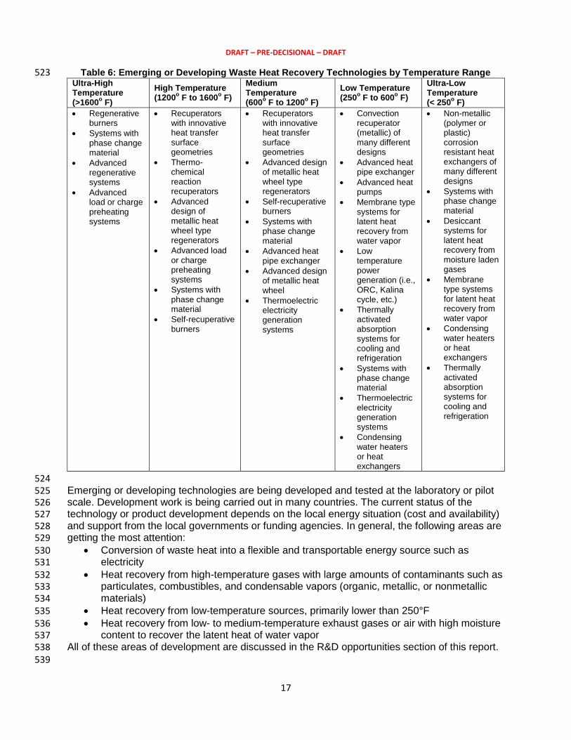
2.1.2. Emerging or Developing Waste Heat Recovery Technologies 520 Table 6 lists emerging technologies that may be used in a few cases, or are in some stage of 521 development and demonstration. 522
DRAFT – PRE-DECISIONAL – DRAFT
17
Table 6: Emerging or Developing Waste Heat Recovery Technologies by Temperature Range 523 Ultra-High Temperature (>1600
o F)
High Temperature (1200
o F to 1600
o F)
Medium Temperature (600
o F to 1200
o F)
Low Temperature (250
o F to 600
o F)
Ultra-Low Temperature (< 250
o F)
Regenerative burners
Systems with phase change material
Advanced regenerative systems
Advanced load or charge preheating systems
Recuperators with innovative heat transfer surface geometries
Thermo-chemical reaction recuperators
Advanced design of metallic heat wheel type regenerators
Advanced load or charge preheating systems
Systems with phase change material
Self-recuperative burners
Recuperators with innovative heat transfer surface geometries
Advanced design of metallic heat wheel type regenerators
Self-recuperative burners
Systems with phase change material
Advanced heat pipe exchanger
Advanced design of metallic heat wheel
Thermoelectric electricity generation systems
Convection recuperator (metallic) of many different designs
Advanced heat pipe exchanger
Advanced heat pumps
Membrane type systems for latent heat recovery from water vapor
Low temperature power generation (i.e., ORC, Kalina cycle, etc.)
Thermally activated absorption systems for cooling and refrigeration
Systems with phase change material
Thermoelectric electricity generation systems
Condensing water heaters or heat exchangers
Non-metallic (polymer or plastic) corrosion resistant heat exchangers of many different designs
Systems with phase change material
Desiccant systems for latent heat recovery from moisture laden gases
Membrane type systems for latent heat recovery from water vapor
Condensing water heaters or heat exchangers
Thermally activated absorption systems for cooling and refrigeration
524 Emerging or developing technologies are being developed and tested at the laboratory or pilot 525 scale. Development work is being carried out in many countries. The current status of the 526 technology or product development depends on the local energy situation (cost and availability) 527 and support from the local governments or funding agencies. In general, the following areas are 528 getting the most attention: 529
Conversion of waste heat into a flexible and transportable energy source such as 530 electricity 531
Heat recovery from high-temperature gases with large amounts of contaminants such as 532 particulates, combustibles, and condensable vapors (organic, metallic, or nonmetallic 533 materials) 534
Heat recovery from low-temperature sources, primarily lower than 250°F 535 Heat recovery from low- to medium-temperature exhaust gases or air with high moisture 536
content to recover the latent heat of water vapor 537 All of these areas of development are discussed in the R&D opportunities section of this report. 538 539
DRAFT – PRE-DECISIONAL – DRAFT
18
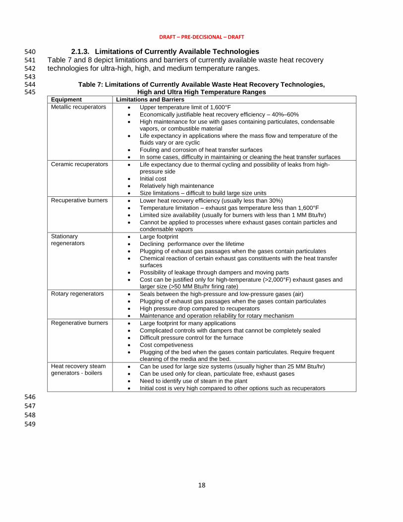
2.1.3. Limitations of Currently Available Technologies 540 Table 7 and 8 depict limitations and barriers of currently available waste heat recovery 541 technologies for ultra-high, high, and medium temperature ranges. 542 543
Table 7: Limitations of Currently Available Waste Heat Recovery Technologies, 544 High and Ultra High Temperature Ranges 545
Equipment Limitations and Barriers
Metallic recuperators Upper temperature limit of 1,600°F
Economically justifiable heat recovery efficiency – 40%–60%
High maintenance for use with gases containing particulates, condensable vapors, or combustible material
Life expectancy in applications where the mass flow and temperature of the fluids vary or are cyclic
Fouling and corrosion of heat transfer surfaces
In some cases, difficulty in maintaining or cleaning the heat transfer surfaces
Ceramic recuperators Life expectancy due to thermal cycling and possibility of leaks from high-pressure side
Initial cost
Relatively high maintenance
Size limitations – difficult to build large size units
Recuperative burners Lower heat recovery efficiency (usually less than 30%)
Temperature limitation – exhaust gas temperature less than 1,600°F
Limited size availability (usually for burners with less than 1 MM Btu/hr)
Cannot be applied to processes where exhaust gases contain particles and condensable vapors
Stationary regenerators
Large footprint
Declining performance over the lifetime
Plugging of exhaust gas passages when the gases contain particulates
Chemical reaction of certain exhaust gas constituents with the heat transfer surfaces
Possibility of leakage through dampers and moving parts
Cost can be justified only for high-temperature (>2,000°F) exhaust gases and larger size (>50 MM Btu/hr firing rate)
Rotary regenerators Seals between the high-pressure and low-pressure gases (air)
Plugging of exhaust gas passages when the gases contain particulates
High pressure drop compared to recuperators
Maintenance and operation reliability for rotary mechanism
Regenerative burners Large footprint for many applications
Complicated controls with dampers that cannot be completely sealed
Difficult pressure control for the furnace
Cost competiveness
Plugging of the bed when the gases contain particulates. Require frequent cleaning of the media and the bed.
Heat recovery steam generators - boilers
Can be used for large size systems (usually higher than 25 MM Btu/hr)
Can be used only for clean, particulate free, exhaust gases
Need to identify use of steam in the plant
Initial cost is very high compared to other options such as recuperators
546 547 548
549

DRAFT – PRE-DECISIONAL – DRAFT
19
Table 8: Limitations of Currently Available Waste Heat Recovery Technologies, 550 Medium Temperature Ranges 551
Equipment Limitations and Barriers
Metallic recuperators
Economic justification for exhaust gas temperature below about 1,000°F
Economically justifiable heat recovery efficiency – 40%–60%
High maintenance for use with gases containing particulates, condensable vapors, or combustible material
Fouling of heat transfer surfaces
In some cases, difficulty in maintaining or cleaning the heat transfer surfaces
Recuperative burners
Lower heat recovery efficiency (usually less than 30%)
Limited size availability (usually for burners with less than 1 MM Btu/hr)
Cannot be applied to processes where exhaust gases contain particles and condensable vapors
Rotary regenerators
Seals between the high-pressure and low-pressure gases (air)
Plugging of exhaust gas passages when the gases contain particulates
High pressure drop compared to recuperators
Maintenance and operation reliability for rotary mechanism
Shell and tube heat exchanger for heating liquid (water)
Fouling of heat transfer surfaces when the gases contain particulates or condensable liquids
Condensation of moisture at selected cold spots and resulting corrosion
552 Another approach would be to develop a matrix according to the type of equipment available in 553 the market. Considerations would include its application range, in terms of temperatures and 554 heat source characteristics; performance level; and limitations with respect to industrial 555 applications. 556 557 558
2.2. R&D Opportunities 559 R&D opportunities are presented in three formats: by temperature range, by major industry, and 560 by research category. 561 562
2.2.1. R&D Opportunities for Various Temperature Ranges 563 The following are lists of R&D opportunities categorized in temperature regimes at which waste 564 heat is available. 565 566
2.2.1.1. Opportunities for High-Temperature Waste Heat Sources 567 This section includes two different categories of high temperatures: 1,200°–1,600°F, and 568 >1,600°F. 569
Heat recovery systems that can handle high-temperature gases with solids and 570 condensable contaminants. These systems can also have internal cleaning systems that 571 allow long-term continuous operation without major maintenance time for cleaning or 572 rebuilding. The systems can be recuperative or regenerative. 573
Materials that can withstand high temperatures and chemical reactions with the waste 574 heat source and the cyclic nature of waste heat in terms of mass flow rates, 575 temperature, or composition. 576
Development of high-temperature phase change materials that can be used by high-577 temperature heat recovery systems to reduce the size of the system and allow tolerance 578 of the cyclic nature of the waste heat source. 579
Development and testing of selective coatings or laminations that are compatible with 580 base materials of construction and can withstand specific contaminants and 581 combustibles in the waste gas streams. 582

DRAFT – PRE-DECISIONAL – DRAFT
20
Systems with smaller footprints that allow installation as a retrofit for existing systems, 583 which are usually located in limited space in the plants. 584
Secondary heat recovery systems that can be used as supplementary or secondary 585 recovery systems to enhance the performance of the existing systems. These systems 586 should be compatible with the performance of the primary systems. 587
A hot gas cleaning system to remove particulates from high-temperature gases. 588 Electrical power generation systems integrated with high-temperature waste heat 589
sources or existing primary heat recovery systems. The electric power generation 590 system must be able to handle variations in heat sources and the cyclic nature of the 591 waste heat source. In most cases, the system must be able to tolerate some 592 contaminants present in the waste heat source. 593
Catalysts for reforming fuel gases or liquid fuel vapors for use in endothermic heat 594 recovery units. 595
596 2.2.1.2. Opportunities for Medium-Temperature Waste Heat Sources 597
This section includes temperatures from 600°–1,200°F. 598 Compact heat exchangers or micro-channel heat exchangers for clean gases that 599
reduce the size or footprint of the heat recovery system. 600 High-performance heat recovery systems that integrate burners and eliminate the need 601
for hot air piping and space for external heat recovery systems. This may require 602 development and integration of micro-channel heat exchangers. 603
Heat transfer systems for gases containing condensable vapors or combustible gases 604 such as solvent vapors in coating ovens. 605
606 2.2.1.3. Opportunities for Low-Temperature Waste Heat Sources 607
This section includes two different categories of low temperatures: <250°F and 250°–600°F. 608 Innovative condensing heat exchangers for gases containing high moisture levels with 609
particulates, as discharged from paper machines, food drying ovens, or other sources. 610 Nonmetallic materials (polymers) that can withstand condensed water from combustion 611
products containing acid gases. These must be cost competitive and used for low-612 temperature condensing heat exchangers. 613
High-efficiency, liquid-gas heat exchangers for low-temperature flue gases or exhaust air 614 from dryers. 615
Liquid-to-liquid heat exchangers for heat recovery from waste water containing 616 particulates and other contaminants. 617
Dry coolers for cooling liquids that reduce or eliminate water use in heat exchangers. 618 A special category of heat recovery systems includes use of waste heat for electric power 619 generation systems and absorption cooling systems for low- and medium-temperature waste 620 heat recovery. R&D needs for this category of waste heat recovery systems include the 621 following: 622
Condenser units (heat exchangers) that replace water with air to reduce the cost of 623 cooling towers and liquid cooling systems. 624
Waste heat exchangers designed for fast startup, low-thermal stresses, low cost, and 625 compact size. 626
Evaporator section heat exchangers with “de-fouling” for glass and other particle-laden 627 exhaust streams. 628
Turbo machinery with variable area inlet nozzles for high turndown. 629 A working fluid pump design with optimized efficiency for vapor compression. The exact 630
design features will vary with the commonly used working fluids used in Rankine cycle 631

DRAFT – PRE-DECISIONAL – DRAFT
21
systems. The unit may include alternates to the pump design, and could potentially 632 crossover into CO2 compression for sequestration. 633
Heat recovery recuperators—advanced design and analysis methods to improve thermal 634 stresses for fast startup. 635
636 2.2.2. R&D Opportunities by Major Industry 637
The following opportunities have been identified where R&D could impact waste heat recovery 638 in the major industries analyzed in this report. 639 640
2.2.2.1. Opportunities for the Aluminum Industry 641 Cleaning high-temperature contaminated gases without cooling them to lower (<300°C) 642
temperatures. 643 Thermoelectric system infrastructure to prepare for higher ZT value materials and for 644
their use in recovering low- to medium-temperature heat, particularly for surface heat 645 losses such as in electrolysis pots. 646
Improved efficiency or lower initial costs for lower temperature power generation 647 systems, such as the Kalina cycle. The developments can include reducing the number 648 of components (such as gas-liquid heat exchangers) or using alternate fluids for the 649 cycle. 650
Removal of tars and organic vapors from the exhaust gases without dropping their 651 temperature to allow heat recovery from the “cleaner” gases. 652
Materials and components that offer reliability and longer life for submerged heating 653 devices for corrosive surroundings, such as molten aluminum or molten glass. 654
655 2.2.2.2. Opportunities for Food (Snack) Manufacturing 656
Development of heat recovery or energy conversion systems for low-temperature 657 (<200°F) heat sources, such as exhaust gases, that may contain water vapor and other 658 contaminates, such as small amount of oil vapors. 659
Development of heat recovery from low-temperature water (<100°F) for plant use. 660 Development of efficient heater systems to reduce energy intensity. 661
662 2.2.2.3. Opportunities for Integrated Steel Industry 663
Secondary heat recovery devices that can supplement and enhance performance of the 664 currently used systems, and are capable of recovering part (less than 50%, in most 665 cases) of the waste heat available. 666
Recovery of waste heat or increasing the value of available heat from blast furnace gas 667 (removal of moisture). 668
Recovery of waste heat in hot products such as hot slabs, rolled steel shapes 669 downstream of the rolling mill, heat treated steel processed in furnaces, and coke 670 discharged from coke oven batteries. In some cases, the technologies exist but are too 671 difficult to implement due to space requirements in existing operations, cost, or lack of 672 use of the low-grade heat produced after heat recovery. The industry has not 673 considered this notion, perhaps due to its nature (low- to medium-grade) and difficulty in 674 recovering and using the heat. 675
Recovery and use of waste heat from highly contaminated hot gases such as hot COG 676 from the ovens. No technology exists or is commercially used in similar cases. 677
Energy recovery through cleaning and recycling steam heat from degasifying systems 678 used for liquid steel refining area. 679
Recovery or utilization of radiation—convection heat from furnace walls or openings, or 680 hot products such as hot steel shapes after rolling. 681

DRAFT – PRE-DECISIONAL – DRAFT
22
Use of low-grade heat in the form of cooling water used in casters or in rolling 682 operations. 683
684 2.2.2.4. Opportunities for the Glass Industry (Fiberglass and others) 685
Heat recovery from very high temperature gases (2,200°F) that contain condensable 686 vapors and produce solid particles that need to be removed. Possible methods include 687 fluidized bed or solid particle-gas heat transfer with a proper material handling system. 688
Rapid quenching methods of hot gases to eliminate generation of sticky solids, and 689 subsequent use of these gases in conventional boilers or air heaters. 690
Electricity generation through direct contact or radiation from moderate temperature 691 (300°–900°F) surfaces with economically justifiable paybacks. Possible methods are 692 thermoelectric and photovoltaic devices under development. 693
Use of advanced heat exchangers for evaporators and condensers that use direct gas-694 air heating for the evaporators and air for condensers. This would eliminate secondary 695 heat exchanger loops such as producing hot water or steam for the evaporators as well 696 as the need for cooling towers for the condenser. This would reduce costs as well as 697 eliminate inefficiencies introduced with the use of secondary heat exchanger circuits. 698
Secondary heat recovery systems for flue gases discharged from regenerators. These 699 gases are at temperatures from 800°–1,200°F. The gas temperature is cyclic and, in 700 some cases, the gases contain very small amount of particulates, which are easy to 701 remove. 702
Glass batch drying and preheating systems using exhaust gases from the melting 703 furnace or refining forehearth section exhaust gases. Previously developed systems 704 have not been used by the industry due to a variety of issues related to operations and 705 maintenance. A new approach or design is required. 706
Hot gas cleanup systems for use by medium- to low-temperature gases prior to 707 secondary heat recovery. 708
Use of CHP systems for generating hot gases for use in annealing ovens. The system 709 will deliver electricity as well as hot air with low oxygen for use as combustion air. 710
Use of heat from annealed products. The heat is available at temperatures below 500°F. 711 712
2.2.2.5. Opportunities for the Paper Industry 713 Development of heat recovery or energy conversion systems for low-temperature 714
(<140°F) heat sources, such as exhaust gases, that may contain water vapor and other 715 contaminates, such as small amount of fibers or duct. 716
A system for dehumidifying high-temperature (≥140°F) air containing fibers or dust. 717 Development of heat recovery from low-temperature water (<100°F) for use in the plant. 718 Development of a drying system for solids, using waste heat from the exhaust gases. 719
720 2.2.2.6. Opportunities for Steel Mini-mills (EAF Furnaces and Rolling Mill) 721
Heat recovery from EAF exhaust gases. Options could include hot gas clean up, 722 controlled combustion of combustibles to manage reaction temperatures while avoiding 723 melting of steel oxides and other solid contaminants, and heat recovery from highly 724 contaminated (e.g., particulate and condensable oil vapors) gases. 725
Recovery of heat from surfaces of hot ladles. The heat is in the form of radiation and 726 convection and the ladles are moved from one location to another during the day. 727
Heat recovery from cooling water used in the continuous casting process and reheat 728 furnace cooling (e.g., walking beam furnaces or thin-slab reheating roller hearth 729 furnaces) 730
DRAFT – PRE-DECISIONAL – DRAFT
23
Secondary heat recovery from reheat furnaces downstream of conventional heat 731 recuperators to recover additional heat. One option is preheating the product entering 732 the furnace. Issues to be addressed include the location of the heat source and heat 733 use, available space, and the infrastructure or logistics of transporting heat to the 734 desired location. 735
Heat recovery from hot cooled products. This could be medium- or low-grade heat. 736 737
2.2.2.7. Opportunities for Coating Plants 738 Secondary heat recovery from regenerative thermal oxidizers (RTOs) exhaust gases 739
that are available from 350°–400°F. 740 Control system for ovens to regulate the amount of make-up air used. This will require 741
development of a system that controls the amount of make-up air, and hence the 742 amount of heat wasted from the oven. 743
744 2.2.2.8. Opportunities for Aluminum Recycling Operations 745
Cleaning of hot gases from rotary furnaces to allow heat recovery from exhaust gases. 746 A heat recovery system for hot (>1,800°F) exhaust gases containing materials such as 747
flux material and aluminum oxide particles. 748 Secondary heat recovery from gases discharged from recuperators used for combustion 749
air preheating. The gases could be in the temperature range of 400°–800°F. 750 751
2.2.2.9. Opportunities for the Cement Industry 752 Heat recovery from hot surfaces or kiln shell surfaces. 753 Cleaning (particulate removal) of heated clinker cooling air prior to its use in boilers or 754
other heat recovery systems. 755 Moisture control or reduction for the raw materials using exhaust gases from heat 756
recovery systems. 757 Use of an alternate (conventional steam boiler or generator) CHP system for generating 758
power using hot air from cooling beds as well as exhaust gases from the system. 759 760
2.2.2.10. Opportunities for the Chemicals and Petroleum Refining Industries 761 Heat recovery from low-temperature (200°F and higher) but relatively clean gases, such 762
as combustion products, from natural gas-fired heaters or boilers. Compact heat 763 exchangers that allow condensation of water vapor and use mediums that use no or 764 minimal water are needed. 765
Treatment of high-temperature gases containing corrosive gases such as HCL from TO 766 gases that includes removing (or reacting) these compounds while allowing heat 767 recovery using conventional heat exchanger equipment. 768
Equipment to recover heat from exothermic processes. The system must be compact 769 and reliable and deliver recovered heat in the form of high-pressure steam or another 770 compact usable form. 771
Development of compact heat exchangers such as micro-channel heat exchangers for 772 use in industrial environments. A major requirement is tolerance of the minor and 773 unpredictable presence of solids or other materials that may adversely affect heat 774 exchanger performance. 775
Development of air-cooled heat exchangers that can replace water-cooled units. This will 776 reduce water and associated energy use. 777
Economically justifiable energy recovery from flared gases. 778 779
2.2.3. R&D Opportunities by Research Category 780

DRAFT – PRE-DECISIONAL – DRAFT
24
The industry requirement-based R&D lists have been consolidated to identify crosscutting R&D 781 that could meet requirements of many different industries and at the same time fill the gaps in 782 capabilities or performance of the currently available systems. While there are many ways the 783 R&D areas could be presented, the following employs the method of dividing R&D activities into 784 specific programs that can be pursued by equipment suppliers to advance the technology or 785 performance of the currently offered systems: 786 787
2.2.3.1. Opportunities in Basic Research 788 Heat transfer 789
o Enhancement of heat transfer for gases or air to reduce the size of heat exchangers. 790 This could include advancements in heat transfer surfaces in shape, configuration, 791 coatings, and changes in fluid flow patterns through innovative flow patterns, 792 changes in gas compositions, or other methods that could make significant 793 improvements in convection heat transfer for the gases. 794
o Radiation heat transfer enhancement to take advantage of thermal radiation 795 emission properties of gases such as CO2 and H2O that are present in combustion 796 products of commonly used fossil fuels. This may include using re-radiation surfaces 797 or other geometrical modifications. 798
Particulate removal or gas cleaning 799 o Particulates filtering for particulate laden gases in all temperature ranges through 800
innovative methods of increasing filtering efficiency with minimized pressure drop. Of 801 particular interest is cleaning or filtering of high-temperature gases encountered in 802 industries such as EAF (mini-mills), glass, cement and lime kilns, aluminum melting, 803 and steel melting. 804
o Innovative methods of avoiding or reducing particulate deposition on heat transfer 805 surfaces. This can be used to retard or remove deposits of organic materials (e.g., oil 806 vapors) or inorganic materials (e.g., Boron vapors) present in glass melting furnaces, 807 ash in coal fired boilers, and oxides in steel or aluminum melting furnaces. 808
o Particulate removal methods for high-temperature heat transfer surfaces, particularly 809 materials deposited at high temperatures. 810
Gas or vapor separation 811 o Selective separation of water vapor or steam, CO2, oil, or organic liquid vapors from 812
exhaust gases at high temperatures (greater than the condensation temperature of 813 the selected materials) without the need for cooling the entire gas mass. This may 814 include membranes or other methods such as high-temperature desiccant or 815 molecular sieves to absorb or adsorb water vapor or other gases selectively. 816
o Reactive systems (i.e., controlled combustion for organic vapors) to remove or 817 collect organic vapors and combustible gases or vapors with controlled reaction rates 818 and temperature increases. 819
820 2.2.3.2. Opportunities in Advanced Materials 821
Corrosion-resistant coatings for low-temperature applications. 822 High-temperature (>1,600°F) corrosion resistant materials for heat exchangers 823
(recuperators). 824 Heat storage materials with high latent heat, thermal capacity (specific heat), and 825
thermal conductivity for all temperature ranges. 826 Seal materials for high-temperature heat exchanger designs with moving parts (e.g., 827
heat wheels or regenerators). The seal can be for metal-to-metal interface or metal-to-828 non-metallic materials (e.g., ceramics). 829
DRAFT – PRE-DECISIONAL – DRAFT
25
Polymers or plastics with improved thermal conductivity for use in low-temperature 830 corrosive environments (e.g., combustion products of fossil fuels). 831
Cost-effective thermoelectric or thermo-ionic materials capable of producing electricity 832 from heat with 15%–20% thermal efficiency. 833
Working fluids for low-temperature power generation cycles that can withstand broader 834 temperature ranges for use in ovens and furnaces. 835
Advanced materials to increase temperature lift in absorption cycles and improve overall 836 heating and cooling performance. 837
Catalysts to support lower temperature “reforming” reactions for use in medium- to high-838 temperature (≥800°F) waste heat applications. 839
Higher temperature materials to be used for “bag-houses,” or gas cleaning systems. This 840 will allow use of lower temperature electricity generation cycles. 841
842 2.2.3.3. Opportunities in Advanced Concepts and Designs 843
Innovative heat transfer methods and heat exchanger geometries to reduce heat 844 exchanger size (see the Basic Research section). 845
Heat exchangers or regenerators with continuous surface cleaning to remove surface 846 deposits resulting from particulates or fibers in waste gas streams. 847
Air cooled (dry) heat exchangers to be used to replace or supplement currently used 848 water cooled condensers or heat exchangers (see the Basic Research section for heat 849 transfer improvement). 850
New concepts for recovering and collecting heat from gases containing particulates and 851 high-temperature condensable materials as encountered in the glass, steel, cement, and 852 aluminum industries. 853
New regenerator designs to reduce the size of high-temperature particulate laden gases, 854 such as using a high surface-area-to-volume ratio or high thermal capacity materials that 855 are easy to clean. 856
Waste heat “boilers” in condensers thermally driven lower temperature (≥100°F) high 857 pressure condensing thermally-activated refrigeration and heat pump systems driven by 858 waste heat to replace or supplement direct gas firing. 859
Pumps and turbo-expanders with high turndown capability for use in low-temperature 860 power generation systems. 861
Self-cleaning filters for gases with relatively low particulate loading. 862 Advanced heat exchangers for evaporators and condensers that use direct gas – air 863
heating for the evaporators and air for condensers. 864 Methods to seal ends of a continuous furnace or oven to reduce or eliminate air leaks 865
that result in excessive energy use in heating equipment; increased size for exhaust gas 866 handling systems; and gas treatment, if necessary for meeting local environmental 867 regulations. 868
869 2.2.3.4. Opportunities in Sensors and Controls 870
Reliable sensors and controls for high-temperature (>400°F) applications to measure 871 and monitor humidity or lower explosion limits (LEL) in dryers and ovens to allow 872 recycling of exhaust gases and reduce the amount of make-up air. 873
Systems for monitoring heat exchanger performance to detect performance degradation 874 and alarms for maintenance. 875
A low cost reliable system for monitoring O2 and CO in small applications (<5 MM Btu/hr 876 fired systems). 877
DRAFT – PRE-DECISIONAL – DRAFT
26
Continuous monitoring of energy intensity (Btu or kWh per unit of production) to identify 878 performance problems. 879
880 2.2.3.5. Opportunities in Advanced High Efficiency Power Generation 881
Systems 882 High turndown systems for use in applications where the waste fired stream heat content 883
(in terms of Btu/hr) changes significantly. 884 Systems with non-water cooled condensers to avoid the need for water and cooling 885
towers. 886 887 3. Risk and Uncertainty, and other Considerations 888 Identify and describe issues related to the following 889
Risk and Uncertainty Issues: As described above, identify risk and uncertainty issues 890 to queue them up for EPSA/QER. Where appropriate, identify how these impacts and 891 need to be taken into account in the R&D work. 892
Technology characteristics impact policy: Identify where technology characteristics 893 impact policy design, and set this up for EPSA/QER. Also describe how policy factors 894 may drive technology considerations and choices. In both cases, don’t explore policies in 895 detail; leave that for EPSA. 896
Other considerations TBD 897 898
4. Sidebars; Case Studies 899 Prepare 2-3 short case studies or vignettes to illustrate key aspects of DOE R&D, including 900
cross-cut activities, enabling science, or other issues, where possible, these should have a clear 901
outcome or conclusion and a strong graphic is desirable. These should be in the form of self-902
standing boxes or side-bars. 903
5. References 904
1. Oak Ridge National Laboratory (ORNL), Industrial Waste Heat Recovery: Potential 905
Applications, Available Technologies and Crosscutting R&D Opportunities, Arvind Thekdi 906
(E3M Inc.) and Sachin Nimbalkar (ORNL), ORNL/TM-2014/622, January 2014. 907
2. Energetics Incorporated and E3M, Incorporated, Energy Use, Loss and Opportunities 908
Analysis: U.S. Manufacturing & Mining, prepared for the U.S. Department of Energy, 909
Industrial Technologies Program, December 2004. 910
3. BCS, Incorporated, Waste Heat Recovery: Technology and Opportunities in U. S. Industry, 911
prepared for the U.S. Department of Energy, Industrial Technologies Program, March 2008. 912
4. Pacific Northwest National Laboratory (PNNL), Opportunity Analysis for Recovering Energy 913
from Industrial Waste Heat and Emissions, prepared for the U.S. Department of Energy, 914
April 2006. 915
5. Pacific Northwest National Laboratory (PNNL) and BCS, Incorporated, Engineering Scoping 916
Study of Thermoelectric Generator (TEG) Systems for Industrial Waste Heat Recovery, 917
prepared for the U.S. Department of Energy, Industrial Technologies Program, November 918
2006. 919
6. Oak Ridge National Laboratory (ORNL) and E3M Inc., Technologies and Materials for 920
Recovering Waste Heat in Harsh Environments, Sachin Nimbalkar, Arvind Thekdi, et.al., 921
ORNL/TM-2014/619. 922

DRAFT – PRE-DECISIONAL – DRAFT
27
7. Lawrence Berkeley National Laboratory (LBNL), Energy Efficiency Improvement and Cost 923
Saving Opportunities For Petroleum Refineries: An ENERGY STAR® Guide for Energy and 924
Plant Managers, prepared for the U.S. Environmental Protection Agency, February 2005. 925
8. Lawrence Berkeley National Laboratory (LBNL) and American Council for an Energy-926
Efficient Economy (ACEEE), Emerging Energy-Efficient Industrial Technologies, October 927
2000. 928
9. McKinsey & Company, Unlocking Energy Efficiency in the U.S. Economy, July 2009. 929
930