draft onondaga lake sediment consolidation area civil ... · sediment consolidation area civil...
TRANSCRIPT

DRAFT ONONDAGA LAKESEDIMENT CONSOLIDATION AREA CIVIL &
GEOTECHNICAL FINAL DESIGN
Parsons p:\honeywell -syr\444853 - lake detail design\09 reports\9.8 sca draft final\appendices\appendix flysheets.doc
12B12BAPPENDIX F
VOLUME CALCULATIONS FOR SCA DESIGN


Page 1 of 32
Written by: Joseph Sura Date: 12/11/2009 Reviewed by: R. Kulasingam Date: 12/15/2009
Client: Honeywell Project: Onondaga Lake SCA Final Design Project/ Proposal No.: GJ4299 Task No.: 18
GA090664/SCA Volume
VOLUME CALCULATIONS FOR SCA DESIGN
INTRODUCTION
This package was prepared in support of the design of the Sediment Consolidation Area (SCA) for the Onondaga Lake Bottom Site, which will be constructed on Wastebed 13 (WB-13). The primary goal of this package is to present capacity calculations for the proposed SCA. Calculations of the thicknesses and volume of the low permeability soil liner, gravel drainage layer, SCA perimeter dike material, and SCA final cover soils are also presented.
CURRENT SCA DESIGN
The Consent Decree (CD) states that the Onondaga Lake remedy includes dredging of up to 2,653,000 cubic yards (cy) of material from Onondaga Lake. This calculation package presents a viable SCA footprint for two dredge volumes: (i) consolidation of the upper bound dredge volume of 2,653,000 cy of material; and (ii) consolidation of a reduced volume of 1,900,000 cy of material.
The current SCA design includes a composite liner system, five layers of geotextile tubes (geo-tubes), and a final cover system, surrounded by a perimeter dike. Based on discussions with New York State Department of Environmental Conservation (NYSDEC), the low-permeability soil layer component of the composite liner system shall have a minimum thickness of 1 ft with a 1.5-ft thickness near the sump areas. A gravel drainage layer with a minimum thickness of 1 ft and an average thickness of approximately 2 ft will be placed above the low-permeability liner. The current design includes stacking of up to five layers of geo-tubes on top of the gravel drainage layer to result in a dewatered total geo-tube height of 30 ft. The geo-tubes are planned to be offset by a minimum distance of ten feet from the SCA perimeter dike. A leveling layer of soil fill will be placed at the base of the SCA in the temporary ditch and above the geo-tubes before final cover placement. The final cover system consists of a leveling layer, a geomembrane, a layer of protective soil with a minimum thickness of 24 inches, and a layer of vegetative soil with a minimum thickness of 6 inches, for a minimum total thickness of approximately 30 inches of soil.
The area difference between the outside SCA perimeter dike edge of the full volume footprint (2,653,000 cy) and reduced volume footprint (1,900,000 cy) footprints is approximately 17 acres (see Figure 1). The east-west dimension is the same for both footprints; therefore, the

Page 2 of 32
Written by: Joseph Sura Date: 12/11/2009 Reviewed by: R. Kulasingam Date: 12/15/2009
Client: Honeywell Project: Onondaga Lake SCA Final Design Project/ Proposal No.: GJ4299 Task No.: 18
GA090664/SCA Volume
SCA is shorter in the north-south direction for the reduced volume footprint as compared to the full volume footprint. This results in the reduced volume footprint having a greater buffer zone between the edge of the SCA and the exterior dike of WB-13.
METHODOLOGY
The calculations presented in this package were computed using the proposed SCA grading plans and AutoCAD 2010. AutoCAD creates 3-D surfaces (Triangular Irregular Network surfaces) based on the contours on the grading plans and uses these surfaces to calculate the volume and thickness of each layer. The thicknesses are then graphed as isopachs, which are contours connecting points of equal thickness.
It is noted that for surface water drainage purposes, the final cover thickness often exceeds the minimum thickness of 30 inches. Based on information provided by Parsons, it is expected that the leveling layer material will be used for the additional thickness. For purposes of this calculation, the 3D surface area of the SCA was calculated using AutoCAD and multiplied by the design thickness of the protective soil layer (24 inches) and vegetative layer (6 inches) to calculate the required soil volumes of these layers. The leveling layer volume was calculated by subtracting the protective soil volume and vegetative soil volume from the total final cover soil volume.
CALCULATIONS
The proposed grading plans for the berm and subgrade, low permeability soil liner, gravel drainage layer, and top of geo-tubes for the full volume footprint are provided in Attachment A, Figures A1 through A4. It is noted that Figures A1 through A4 have been prepared for purposes of calculating required material volumes and the SCA storage capacity; therefore, settlement has not been accounted for in these figures. The proposed final cover grading has been designed using the top of geo-tube grading after four years of settlement to promote surface water drainage post-closure. Figures A5 and A6 show the calculated top of geo-tube grading after four years of settlement and the proposed final cover grading plan, respectively.
The calculated total dredge material capacity for the full volume footprint is calculated as the difference between the grades shown in Figures A4 and A3 and is shown in Figure 2. Isopachs of the low permeability soil liner (difference between Figures A2 and A1) and gravel drainage layer (difference between Figures A3 and A2) are shown in Figures 3 and 4, respectively. The calculated SCA final cover soil volume is calculated as the difference between the post year 4 settled geo-tubes and the proposed final cover grading (Figures A5 and A6) and is shown in Figure 5. It is noted that this isopach represents the combined thickness of the leveling

Page 3 of 32
Written by: Joseph Sura Date: 12/11/2009 Reviewed by: R. Kulasingam Date: 12/15/2009
Client: Honeywell Project: Onondaga Lake SCA Final Design Project/ Proposal No.: GJ4299 Task No.: 18
GA090664/SCA Volume
layer, protective soil layer and vegetative layer. The calculated SCA perimeter dike volume for the full volume footprint is calculated as the difference between the existing grades and the proposed berm grading plan shown in Figure A1 and is shown in Figure 6.
The proposed grading plans for the berm and subgrade, low permeability soil liner, gravel drainage layer, and top of geo-tubes for the reduced volume footprint are provided in Attachment B, Figures B1 through B4. It is noted that Figures B1 through B4 have been prepared for purposes of calculating required material volumes and the SCA storage capacity; therefore, settlement has not been accounted for in these figures. The proposed final cover grading has been designed using the top of geo-tube grading after four years of settlement to promote surface water drainage post-closure. Figures B5 and B6 show the calculated top of geo-tube grading after four years of settlement and the proposed final cover grading plan, respectively.
The calculated total dredge material capacity for the reduced volume footprint is calculated as the difference between the grades shown in Figures B4 and B3 and is shown in Figure 7. Isopachs of the low permeability soil liner (difference between Figures B2 and B1) and gravel drainage layer (difference between Figures B3 and B2) are shown in Figures 8 and 9, respectively. The calculated SCA final cover soil volume is calculated as the difference between the post year 4 settled geo-tubes and the proposed final cover grading (Figures B5 and B6) and is shown in Figure 10. It is noted that this isopach represents the combined thickness of the leveling layer, protective soil layer and vegetative layer. The calculated SCA perimeter dike volume for the reduced volume footprint is calculated as the difference between the existing grades and the proposed berm grading plan (Figure B1) and is shown in Figure 11.
RESULTS
The calculated SCA capacity for dredge material and volumes of low-permeability soil, gravel drainage material, SCA perimeter dike material, and SCA final cover soils for the full volume and reduced volume footprints are shown in Table 1. The results indicate that the proposed SCA full volume and reduced volume footprints meet their respective target capacities. For the full volume footprint, the SCA footprint was estimated to be approximately 75 acres to the outside of the SCA perimeter dike (not including the stormwater basins) and approximately 65 acres to the inside of the SCA perimeter dike (not including the stormwater basins). The average thicknesses of low permeability soil and gravel drainage material were calculated to be 2.6 ft and 2.0 ft, respectively. For the reduced volume footprint, the SCA footprint was estimated to be approximately 58 acres to the outside of the SCA perimeter dike (not including

Page 4 of 32
Written by: Joseph Sura Date: 12/11/2009 Reviewed by: R. Kulasingam Date: 12/15/2009
Client: Honeywell Project: Onondaga Lake SCA Final Design Project/ Proposal No.: GJ4299 Task No.: 18
GA090664/SCA Volume
the stormwater basins) and approximately 49 acres to the inside of the SCA perimeter dike (not including the stormwater basins). The average thicknesses of low permeability soil and gravel drainage material were calculated to be 2.6 ft and 2.1 ft, respectively. Review of Figures 3 and 8 (for the full volume and reduced volume, respectively) indicates that the low permeability soil layer has a minimum thickness of 1 ft in the SCA footprint with a thickness of at least 1.8 ft near the sump areas. Also, the review of Figures 4 and 9 (for the full volume and reduced volume, respectively) indicates that the gravel drainage layer has a minimum thickness of 1 ft in the SCA footprint with a thickness of at least 4 ft near the sump areas.
Page 5 of 32
Written by: Joseph Sura Date: 12/11/2009 Reviewed by: R. Kulasingam Date: 12/15/2009
Client: Honeywell Project: Onondaga Lake SCA Final Design Project/ Proposal No.: GJ4299 Task No.: 18
GA090664/SCA Volume
Tables

Page 6 of 32
Written by: Joseph Sura Date: 12/11/2009 Reviewed by: R. Kulasingam Date: 12/15/2009
Client: Honeywell Project: Onondaga Lake SCA Final Design Project/ Proposal No.: GJ4299 Task No.: 18
GA090664/SCA Volume
Full Volume
2,771,106 270,591 203,745 174,047 221,197 55,299 87,251
Reduced Volume
2,039,873 207,443 167,370 151,565 163,981 40,995 86,993
Table 1: Calculated Volumes (cy)
Perimeter DikeGravel Drainage
MaterialLow Permeability
ClayGeo‐tube Capacity
Final Cover Protective Soil
Final Cover Leveling Layer
Final Cover Vegetative Soil
Notes:
1. The vegetative soil and protective soil volumes shown here are calculated based on the 3D surface area of these layers. The calculated 3D surface area of the final cover for the full volume footprint is 2,986,160 ft2 and the calculated 3D surface area of the final cover for the reduced volume footprint is 2,213,745 ft2.
2. The leveling layer volume is then calculated from the total final cover soil volume shown in Figures 5 and 10 for the full volume and reduced volume, respectively.
3. The perimeter dike volume shown here includes the soil necessary to build the dikes for the SCA and the temporary stormwater basins.

Page 7 of 32
Written by: Joseph Sura Date: 12/11/2009 Reviewed by: R. Kulasingam Date: 12/15/2009
Client: Honeywell Project: Onondaga Lake SCA Final Design Project/ Proposal No.: GJ4299 Task No.: 18
GA090664/SCA Volume
Figures

Page 8 of 32
Written by: Joseph Sura Date: 12/11/2009 Reviewed by: R. Kulasingam Date: 12/15/2009
Client: Honeywell Project: Onondaga Lake SCA Final Design Project/ Proposal No.: GJ4299 Task No.: 18
GA090664/SCA Volume
Figure 1: Proposed SCA Full Volume and Reduced Volume Footprints

Page 9 of 32
Written by: Joseph Sura Date: 12/11/2009 Reviewed by: R. Kulasingam Date: 12/15/2009
Client: Honeywell Project: Onondaga Lake SCA Final Design Project/ Proposal No.: GJ4299 Task No.: 18
GA090664/SCA Volume
Figure 2: Full Volume Footprint Total Capacity (2.65 million cy)
30 18
30 18

Page 10 of 32
Written by: Joseph Sura Date: 12/11/2009 Reviewed by: R. Kulasingam Date: 12/15/2009
Client: Honeywell Project: Onondaga Lake SCA Final Design Project/ Proposal No.: GJ4299 Task No.: 18
GA090664/SCA Volume
Figure 3: Full Volume Footprint Isopach of Low Permeability Soil Liner Thickness (2.65 million cy)

Page 11 of 32
Written by: Joseph Sura Date: 12/11/2009 Reviewed by: R. Kulasingam Date: 12/15/2009
Client: Honeywell Project: Onondaga Lake SCA Final Design Project/ Proposal No.: GJ4299 Task No.: 18
GA090664/SCA Volume
Figure 4: Full Volume Footprint Isopach of Gravel Drainage Layer Thickness for (2.65 million cy)

Page 12 of 32
Written by: Joseph Sura Date: 12/11/2009 Reviewed by: R. Kulasingam Date: 12/15/2009
Client: Honeywell Project: Onondaga Lake SCA Final Design Project/ Proposal No.: GJ4299 Task No.: 18
GA090664/SCA Volume
Figure 5: Full Volume Footprint Isopach of Final Cover Thickness (2.65 million cy)

Page 13 of 32
Written by: Joseph Sura Date: 12/11/2009 Reviewed by: R. Kulasingam Date: 12/15/2009
Client: Honeywell Project: Onondaga Lake SCA Final Design Project/ Proposal No.: GJ4299 Task No.: 18
GA090664/SCA Volume
Figure 6: Full Volume Footprint Isopach of Berm Thickness (2.65 million cy)

Page 14 of 32
Written by: Joseph Sura Date: 12/11/2009 Reviewed by: R. Kulasingam Date: 12/15/2009
Client: Honeywell Project: Onondaga Lake SCA Final Design Project/ Proposal No.: GJ4299 Task No.: 18
GA090664/SCA Volume
Figure 7: Reduced Volume Footprint Total Capacity (1.9 million cy)

Page 15 of 32
Written by: Joseph Sura Date: 12/11/2009 Reviewed by: R. Kulasingam Date: 12/15/2009
Client: Honeywell Project: Onondaga Lake SCA Final Design Project/ Proposal No.: GJ4299 Task No.: 18
GA090664/SCA Volume
Figure 8: Reduced Volume Footprint Isopach of Low Permeability Soil Liner Thickness (1.9 million cy)

Page 16 of 32
Written by: Joseph Sura Date: 12/11/2009 Reviewed by: R. Kulasingam Date: 12/15/2009
Client: Honeywell Project: Onondaga Lake SCA Final Design Project/ Proposal No.: GJ4299 Task No.: 18
GA090664/SCA Volume
Figure 9: Reduced Volume Footprint Isopach of Gravel Drainage Layer Thickness for (1.9 million cy)

Page 17 of 32
Written by: Joseph Sura Date: 12/11/2009 Reviewed by: R. Kulasingam Date: 12/15/2009
Client: Honeywell Project: Onondaga Lake SCA Final Design Project/ Proposal No.: GJ4299 Task No.: 18
GA090664/SCA Volume
Figure 10: Reduced Volume Footprint Isopach of Final Cover Thickness for (1.9 million cy)

Page 18 of 32
Written by: Joseph Sura Date: 12/11/2009 Reviewed by: R. Kulasingam Date: 12/15/2009
Client: Honeywell Project: Onondaga Lake SCA Final Design Project/ Proposal No.: GJ4299 Task No.: 18
GA090664/SCA Volume
Figure 11: Reduced Volume Footprint Isopach of Berm Thickness (1.9 million cy)

Page 19 of 32
Written by: Joseph Sura Date: 12/11/2009 Reviewed by: R. Kulasingam Date: 12/15/2009
Client: Honeywell Project: Onondaga Lake SCA Final Design Project/ Proposal No.: GJ4299 Task No.: 18
GA090664/SCA Volume
Attachment A: Full Volume Footprint Grading Plans

Page 20 of 32
Written by: Joseph Sura Date: 12/11/2009 Reviewed by: R. Kulasingam Date: 12/15/2009
Client: Honeywell Project: Onondaga Lake SCA Final Design Project/ Proposal No.: GJ4299 Task No.: 18
GA090664/SCA Volume
Figure A1: Full Volume Footprint Proposed Berm and Subgrade Grading Plan (2.65 million cy)
Note: This grading plan was prepared for the purpose of calculating the required soil volumes to construct the SCA and therefore settlement has not been accounted for in this figure.
Page 21 of 32
Written by: Joseph Sura Date: 12/11/2009 Reviewed by: R. Kulasingam Date: 12/15/2009
Client: Honeywell Project: Onondaga Lake SCA Final Design Project/ Proposal No.: GJ4299 Task No.: 18
GA090664/SCA Volume
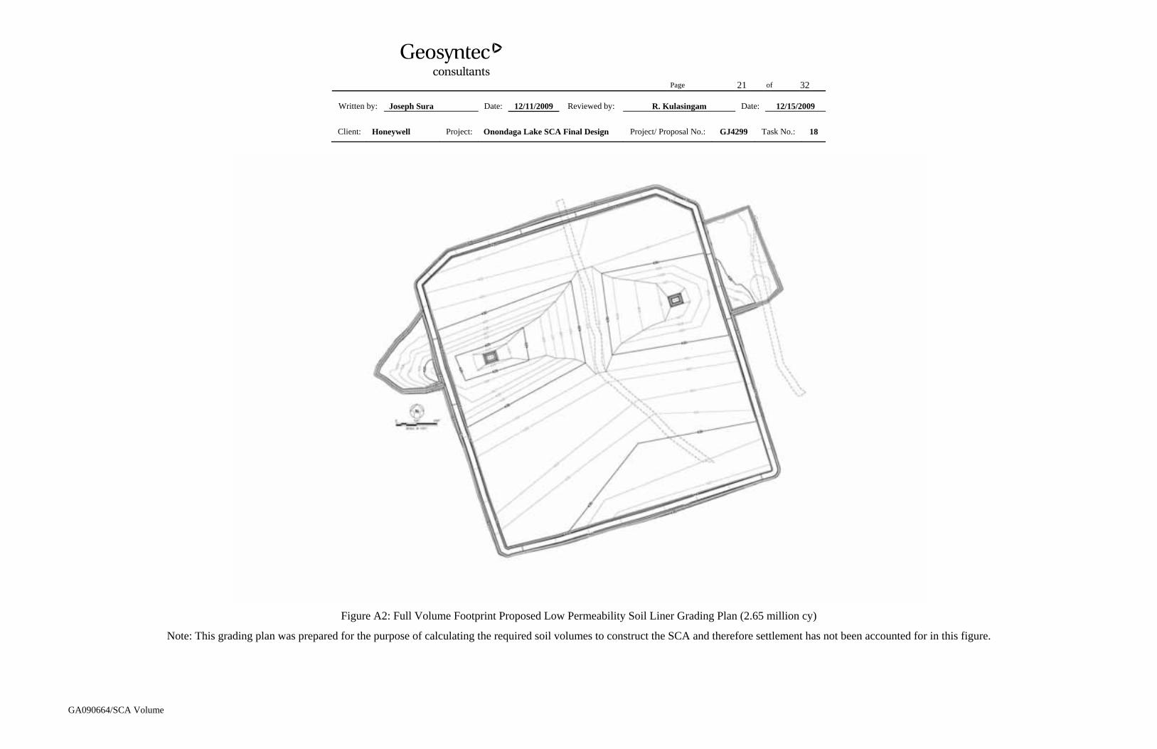
Figure A2: Full Volume Footprint Proposed Low Permeability Soil Liner Grading Plan (2.65 million cy)
Note: This grading plan was prepared for the purpose of calculating the required soil volumes to construct the SCA and therefore settlement has not been accounted for in this figure.

Page 22 of 32
Written by: Joseph Sura Date: 12/11/2009 Reviewed by: R. Kulasingam Date: 12/15/2009
Client: Honeywell Project: Onondaga Lake SCA Final Design Project/ Proposal No.: GJ4299 Task No.: 18
GA090664/SCA Volume
Figure A3: Full Volume Footprint Proposed Gravel Drainage Layer Grading Plan (2.65 million cy)
Note: This grading plan was prepared for the purpose of calculating the required soil volumes to construct the SCA and therefore settlement has not been accounted for in this figure.

Page 23 of 32
Written by: Joseph Sura Date: 12/11/2009 Reviewed by: R. Kulasingam Date: 12/15/2009
Client: Honeywell Project: Onondaga Lake SCA Final Design Project/ Proposal No.: GJ4299 Task No.: 18
GA090664/SCA Volume
Figure A4: Full Volume Footprint Proposed Top of Geo-tube Grading Plan (2.65 million cy)
Note: This grading plan was prepared for the purpose of calculating the storage capacity of the SCA and therefore settlement has not been accounted for in this figure.

Page 24 of 32
Written by: Joseph Sura Date: 12/11/2009 Reviewed by: R. Kulasingam Date: 12/15/2009
Client: Honeywell Project: Onondaga Lake SCA Final Design Project/ Proposal No.: GJ4299 Task No.: 18
GA090664/SCA Volume
Figure A5: Full Volume Footprint Calculated Year 4 Post-Settlement Top of Geo-tube Grading Plan (2.65 million cy)
Page 25 of 32
Written by: Joseph Sura Date: 12/11/2009 Reviewed by: R. Kulasingam Date: 12/15/2009
Client: Honeywell Project: Onondaga Lake SCA Final Design Project/ Proposal No.: GJ4299 Task No.: 18
GA090664/SCA Volume
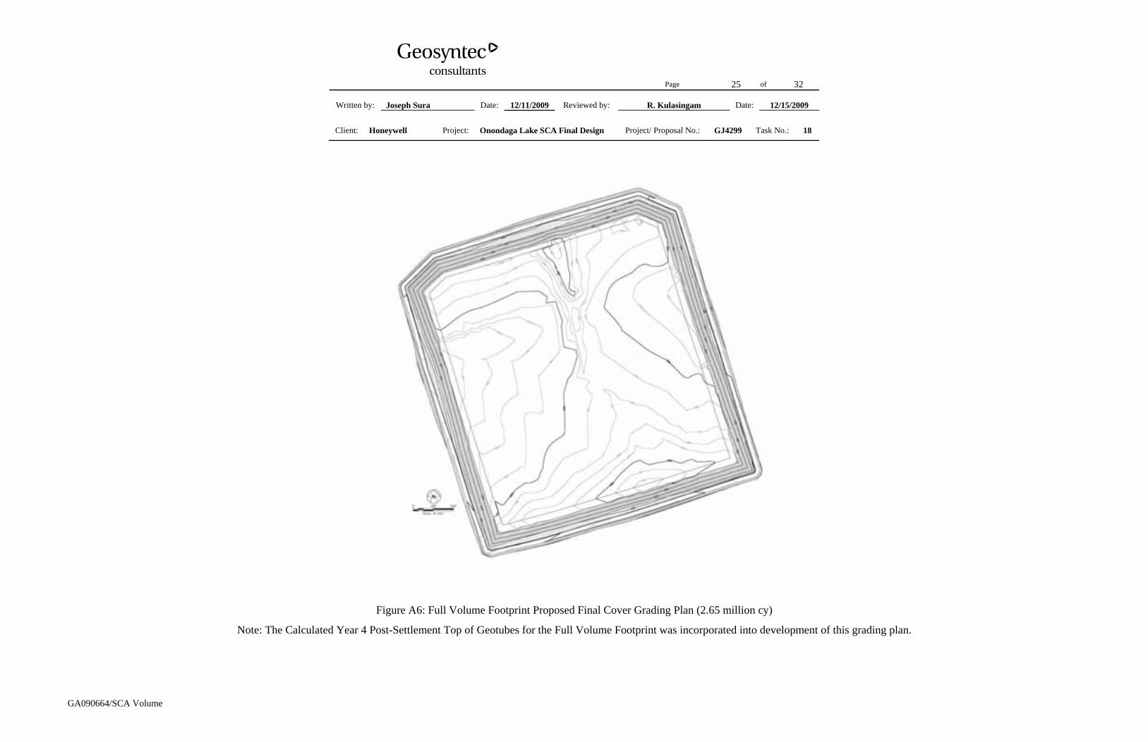
Figure A6: Full Volume Footprint Proposed Final Cover Grading Plan (2.65 million cy)
Note: The Calculated Year 4 Post-Settlement Top of Geotubes for the Full Volume Footprint was incorporated into development of this grading plan.

Page 26 of 32
Written by: Joseph Sura Date: 12/11/2009 Reviewed by: R. Kulasingam Date: 12/15/2009
Client: Honeywell Project: Onondaga Lake SCA Final Design Project/ Proposal No.: GJ4299 Task No.: 18
GA090664/SCA Volume
Attachment B: Reduced Volume Footprint Grading Plans

Page 27 of 32
Written by: Joseph Sura Date: 12/11/2009 Reviewed by: R. Kulasingam Date: 12/15/2009
Client: Honeywell Project: Onondaga Lake SCA Final Design Project/ Proposal No.: GJ4299 Task No.: 18
GA090664/SCA Volume
Figure B1: Reduced Volume Footprint Proposed Berm and Subgrade Grading Plan (1.9 million cy)
Note: This grading plan was prepared for the purpose of calculating the required soil volumes to construct the SCA and therefore settlement has not been accounted for in this figure.

Page 28 of 32
Written by: Joseph Sura Date: 12/11/2009 Reviewed by: R. Kulasingam Date: 12/15/2009
Client: Honeywell Project: Onondaga Lake SCA Final Design Project/ Proposal No.: GJ4299 Task No.: 18
GA090664/SCA Volume
Figure B2: Reduced Volume Footprint Proposed Low Permeability Soil Liner Grading Plan for (1.9 million cy)
Note: This grading plan was prepared for the purpose of calculating the required soil volumes to construct the SCA and therefore settlement has not been accounted for in this figure.

Page 29 of 32
Written by: Joseph Sura Date: 12/11/2009 Reviewed by: R. Kulasingam Date: 12/15/2009
Client: Honeywell Project: Onondaga Lake SCA Final Design Project/ Proposal No.: GJ4299 Task No.: 18
GA090664/SCA Volume
Figure B3: Reduced Volume Footprint Proposed Gravel Drainage Layer Grading Plan for (1.9 million cy)
Note: This grading plan was prepared for the purpose of calculating the required soil volumes to construct the SCA and therefore settlement has not been accounted for in this figure.

Page 30 of 32
Written by: Joseph Sura Date: 12/11/2009 Reviewed by: R. Kulasingam Date: 12/15/2009
Client: Honeywell Project: Onondaga Lake SCA Final Design Project/ Proposal No.: GJ4299 Task No.: 18
GA090664/SCA Volume
Figure B4: Reduced Volume Footprint Proposed Top of Geo-tube Grading Plan for (1.9 million cy)
Note: This grading plan was prepared for the purpose of calculating the storage capacity of the SCA and therefore settlement has not been accounted for in this figure.

Page 31 of 32
Written by: Joseph Sura Date: 12/11/2009 Reviewed by: R. Kulasingam Date: 12/15/2009
Client: Honeywell Project: Onondaga Lake SCA Final Design Project/ Proposal No.: GJ4299 Task No.: 18
GA090664/SCA Volume
Figure B5: Reduced Volume Footprint Calculated Year 4 Post-Settlement Top of Geo-tube Grading Plan for (1.9 million cy)

Page 32 of 32
Written by: Joseph Sura Date: 12/11/2009 Reviewed by: R. Kulasingam Date: 12/15/2009
Client: Honeywell Project: Onondaga Lake SCA Final Design Project/ Proposal No.: GJ4299 Task No.: 18
GA090664/SCA Volume
Figure B6: Reduced Volume Footprint Proposed Final Cover Grading Plan for (1.9 million cy)
Note: The Calculated Year 4 Post-Settlement Top of Geotubes for the Reduced Volume Footprint was incorporated into development of this grading plan.
DRAFT ONONDAGA LAKESEDIMENT CONSOLIDATION AREA CIVIL &
GEOTECHNICAL FINAL DESIGN
Parsons p:\honeywell -syr\444853 - lake detail design\09 reports\9.8 sca draft final\appendices\appendix flysheets.doc
12B12BAPPENDIX G
SLOPE STABILITY ANALYSES FOR SCA DESIGN


Page 1 of 212
Written by: Joseph Sura Date: 12/4/2009 Reviewed by: R. Kulasingam/Jay Beech Date: 12/8/2009
Client: Honeywell Project: Onondaga Lake SCA Final Design Project/ Proposal No.: GJ4299 Task No.: 18
GA090662/SCA Stability
SLOPE STABILITY ANALYSES FOR SCA DESIGN
INTRODUCTION
This package was prepared in support of the design of the Sediment Consolidation Area (SCA) for the Onondaga Lake Bottom Site, which will be constructed on Wastebed 13 (WB-13). Specifically, this package presents static slope stability analyses for the SCA, which will contain geotextile tubes (geo-tubes) filled with dredged material surrounded by a perimeter dike (SCA perimeter dike). For purposes of this calculation package, the SCA perimeter dike refers to the dike that will be constructed around the geo-tubes within WB-13; whereas, the WB-13 perimeter dike refers to the exterior perimeter dike around WB-13.
Seismic slope stability analyses were not performed because the site is not located in a seismic impact zone, as defined by New York State Department of Environmental Conservation (NYSDEC) Regulations Section 360-2.7(b)(7). A detailed explanation regarding the seismic impact zone assessment is presented in Attachment 1 of this package.
METHODOLOGY
Static Slope Stability
Static slope stability analyses were performed using Janbu’s method and Spencer’s method, using the computer program SLIDE version 5.043 [Rocscience, 2009]. Four potential slip modes were evaluated in the analyses: (i) block slip mode along geo-tube interfaces; (ii) block slip mode along the liner system; (iii) circular slip surfaces through dredge material contained in geo-tubes and WB-13 foundation materials; and (iv) circular slip surfaces through existing WB-13 perimeter dikes.
Spencer’s method [Spencer, 1973] satisfies both force and moment equilibrium and is therefore considered more rigorous than other methods, such as Janbu’s method [Janbu, 1973] and the simplified Bishop method [Bishop, 1955]. However, Spencer’s method often encounters numerical convergence difficulties when considering block slip surfaces. Therefore, Spencer’s method was used for the circular slip surfaces, while Janbu’s method was used for block slip surfaces.
Information required for the static slope stability analyses included the slope geometry, the subsurface soil stratigraphy, the groundwater table elevation, the material properties of the

Page 2 of 212
Written by: Joseph Sura Date: 12/4/2009 Reviewed by: R. Kulasingam/Jay Beech Date: 12/8/2009
Client: Honeywell Project: Onondaga Lake SCA Final Design Project/ Proposal No.: GJ4299 Task No.: 18
GA090662/SCA Stability
subsurface soils, dredge material, liner and cover system materials, and the external surface loading, if any, at the selected cross section locations.
Target Factor of Safety
Target factors of safety (FSs) were considered for slope stability of the proposed SCA, one for the interim condition and one for the long-term condition. The interim condition is the condition during the SCA construction and dredge operation period and shortly after the SCA is capped with the final cover system. The long-term condition is the condition a relatively long time after the SCA is capped. In addition, both peak and residual shear strengths were considered in identifying the appropriate FSs for interim and final conditions, as appropriate for geosynthetic materials.
The target FS corresponding to the peak shear strength was considered to be 1.3 for the interim condition and 1.5 for the long-term condition according to U.S. Army Engineer Waterways Experiment Station Technical Report D-77-9 [Hammer and Blackburn, 1977] and U.S. Army Corps of Engineers Engineering Manual 1110-2-1902 [USACE, 2003]. The target FS corresponding to large displacement (i.e., residual) shear strength was considered to be 1.1 for the interim condition and 1.3 for the long-term condition, consistent with general engineering practice.
SUBSURFACE STRATIGRAPHY
Detailed information regarding the subsurface stratigraphy was presented in a calculation package titled “Subsurface Stratigraphy Model of Wastebed 13 for the Design of Sediment Consolidation Area” (referred to as the Data Package). In summary, the subsurface stratigraphy consists primarily of three types of material: the Solvay waste (SOLW), the existing WB-13 perimeter dike soil, and the foundation soil, as shown schematically in Figure 1. The SOLW was divided into three zones (i.e., Zone 1, Zone 2, and Zone 3, as shown in the figure) based on its distinct characteristics.
The groundwater table was found to be approximately 50 ft below ground surface (bgs) of the wastebed (or at approximately El. 375 ft) as presented in the Data Package. However, it is noted that “perched” water zones exist in WB-13 according to the site investigation results presented in the Data Package. These “perched” water zones vary spatially and seasonally according to the piezometer data presented in the Data Package but have an average elevation of approximately 15 ft bgs. The slope stability analysis presented in this package conservatively assumes the “perched” water zones are connected to the groundwater table. The groundwater

Page 3 of 212
Written by: Joseph Sura Date: 12/4/2009 Reviewed by: R. Kulasingam/Jay Beech Date: 12/8/2009
Client: Honeywell Project: Onondaga Lake SCA Final Design Project/ Proposal No.: GJ4299 Task No.: 18
GA090662/SCA Stability
table was, therefore, modeled using a single groundwater table 15 ft bgs. Additionally, within the gravel drainage layer in the liner system, a second water table one foot above the top of the liner layer was assumed in the model. This represents the one foot maximum allowable head within the gravel drainage layer. It should be noted that this water table is confined by the liner system and will only affect the gravel drainage layer in the slope stability analysis.
ANALYZED CROSS-SECTIONS
The proposed SCA consists of a single containment cell surrounded by the SCA perimeter dike as shown in Figure 2. Two cross sections (i.e., Cross-Section A-A and B-B, as shown in Figures 3 and 4) were analyzed for static slope stability. As can be seen in Figure 3, Cross-Section A-A has significantly more vertical interfaces to consider than Cross-Section B-B because of geo-tube orientation. The design height of the proposed SCA perimeter dikes is a minimum of 5 ft above the existing ground surface and a minimum of 2 ft above the top of the gravel at the same location. The elevations of the dikes will vary, as the existing ground elevations vary along the perimeter. The maximum dike height is approximately 10 ft, located near the western sump area. The SCA perimeter dikes are approximately 28 ft wide at the top and have a 2.5 horizontal:1 vertical (2.5H:1V) side slope. There is a 10 ft setback distance between the edge of the lowest geo-tube layer and the dikes.
Cross-Section A-A
Cross-Section A-A was selected because it follows the direction of minimum overlap between the geo-tube stacks, which is expected to result in the lowest FS for block slip mode stability. Cross-Section A-A runs approximately north-south through WB-13. The geo-tubes are assumed to be 40 ft in width and between 250 ft to 320 ft in length. In the direction of Cross-Section A-A, each additional stack of geo-tubes will straddle geo-tubes that are already in place. This results in each stack of geo-tubes being offset approximately 20 feet from the layer below.
The existing ground below the liner at Cross-Section A-A (i.e., top of existing SOLW elevation) is naturally sloped. The thickness of the SOLW underneath the liner varies, but typically is between 50 and 60 ft. Cross-Section A-A was extended to include the existing WB-13 perimeter dike.
Cross-Section B-B
Cross-Section B-B runs approximately east-west through WB-13. In this direction, the geo-tubes are assumed to be between 250 ft and 320 ft long for purposes of this analysis. At the edge

Page 4 of 212
Written by: Joseph Sura Date: 12/4/2009 Reviewed by: R. Kulasingam/Jay Beech Date: 12/8/2009
Client: Honeywell Project: Onondaga Lake SCA Final Design Project/ Proposal No.: GJ4299 Task No.: 18
GA090662/SCA Stability
of the geo-tube layers, tubes are offset approximately 20 ft. Through the interior of the SCA, the offsets between geo-tube layers vary because of the different lengths and number of geo-tubes per layer, but is planned to be a minimum of 20 ft.
MATERIAL PROPERTIES
Table 1 summarizes the material properties (i.e., unit weights and shear strengths) of the SOLW, the dike soil, the foundation soil, the dredged material, the final cover soil, and geosynthetic materials used in the slope stability analyses. The unit weight and the shear strength of the SOLW in WB-13 were considered to be the same for Zone 1, Zone 2, and Zone 3 according to the Data Package. In the stability models presented in this package, the existing WB-13 perimeter dike soil was treated the same as the base foundation material based on previous investigations indicating that these existing WB-13 perimeter dikes were constructed using the native foundation material from beneath WB-13. The term “dike soil” as used in this package therefore refers only to the SCA perimeter dikes that will be constructed. The interfaces between adjacent geo-tubes and between the bottom geo-tube and gravel drainage layer are modeled as thin layers of frictional material. For purposes of this analysis, the final cover is assumed to have a thickness of 3 ft. Figures 5 and 6 show a representation of the layers included in the model.
Unit Weight
The unit weights of the SOLW, the dike soil, and the foundation soil were considered to be 82 pcf, 120 pcf, and 120 pcf, respectively, according to the Data Package. The unit weights of the proposed liner soil and gravel drainage layer were assumed to be 100 pcf and 120 pcf, respectively. The unit weight of the interface between the gravel drainage layer and the geo-tubes was assumed to have the same calculated unit weight as the dredge material (i.e., 86 pcf). The unit weight of the dredged material was calculated to be approximately 86 pcf as presented in Attachment 2 to the package titled “Settlement Analyses for SCA” (Appendix H of the IDS). It is noted that the interfaces were required to be assigned material properties for numerical stability of the SLIDE program. The unit weight of horizontal interfaces between geo-tubes was assumed to be 86 pcf (i.e., the same as the dredge material) because there is no potential for a gap between two stacks of geo-tubes along a horizontal interface. However, due to the ellipsoidal shape of the filled geo-tubes, there is potential for gaps between two adjacent geo-tubes along a vertical interface. Therefore, vertical interfaces between geo-tubes were assumed to have a unit weight of 43 pcf (i.e., half of the dredge material). It is noted that the use of half of the unit weight versus the full unit weight along vertical interfaces is not expected to

Page 5 of 212
Written by: Joseph Sura Date: 12/4/2009 Reviewed by: R. Kulasingam/Jay Beech Date: 12/8/2009
Client: Honeywell Project: Onondaga Lake SCA Final Design Project/ Proposal No.: GJ4299 Task No.: 18
GA090662/SCA Stability
cause significant differences in the calculation results. The unit weight of the final cover soil was assumed to be 120 pcf.
Drained Shear Strength
The drained shear strength was used for the slope stability analyses under the long-term condition. The effective stress friction angles of the SOLW, the dike soil, and the foundation soil were considered to be 34 degrees, 35 degrees, and 37 degrees, respectively, according to the Data Package. For the liner system, laboratory interface direct shear testing was performed on four liner types (i.e., smooth and textured high density polyethylene [HDPE], ethylene propylene diene monomer [EPDM], and polypropylene [PP]), and the results are included in Attachment 2. The peak effective stress friction angle of the proposed liner system varied depending on the type of geomembrane (GM) chosen. Based on these results, smooth HDPE GM is not being considered for use on this project. Among the remaining GM options tested, the peak effective stress friction angle varied from 19 degrees to 27 degrees; therefore, 19 degrees was conservatively assumed in Table 1. The effective stress friction angle of the gravel layer was assumed to be 38 degrees.
The effective stress friction angle for the interface between the bottom geo-tube layer and the gravel drainage layer was considered to be 24 degrees, based on data presented by Koerner [1994] for the interface between woven geotextiles and sand. The geotextiles composing the geo-tubes are modeled as two-end anchored geotextile sheets. The ultimate tensile strength was assumed to be 4800 lb/ft based on standard strength parameters for commercially available geo-tubes. A reduction factor of 3.0 [GRI, 1992] was then applied to result in a design tensile strength of 1600 lb/ft. Current information indicates the dredge material from the In Lake Waste Deposit (ILWD) has a drained friction angle of 37 degrees and, as indicated previously, the existing SOLW in WB-13 has a drained friction angle of 34 degrees. Considering the dredge material as remolded SOLW, the long-term drained effective stress friction angle of the dredge material was conservatively assumed to be 30 degrees. Under short-term conditions, the dredge material was assumed to have half of the drained effective stress friction angle of the material under long-term conditions (i.e., 15 degrees).
The effective stress friction angle of the vertical geo-tube/geo-tube interface was assumed to be negligible due to gaps between the geo-tubes. A value of 0.1 degrees was chosen for this interface to maintain numerical stability of the SLIDE program. Using representative geo-tube samples, the peak effective stress friction angle of the horizontal geo-tube/geo-tube interface was measured to be 15 degrees in laboratory interface direct shear testing (see Attachment 2 for

Page 6 of 212
Written by: Joseph Sura Date: 12/4/2009 Reviewed by: R. Kulasingam/Jay Beech Date: 12/8/2009
Client: Honeywell Project: Onondaga Lake SCA Final Design Project/ Proposal No.: GJ4299 Task No.: 18
GA090662/SCA Stability
results), which is the assumed value provided in Table 1. The effective stress friction angle for the final cover was assumed to be 30 degrees.
At the time this package was initially prepared, the GM component in the final liner system had not been selected; therefore the minimum measured interface friction values of 19 degrees (peak) and 17 degrees (residual) were selected. Once the critical stability cases were established using the minimum value of liner system friction angle from laboratory testing, the critical cases were rerun using the maximum liner system friction angle (both peak and residual) from laboratory testing. These analyses were performed to provide an approximate range of FS values that may be expected. The peak and residual interface friction angles for linear low-density polyethylene (LLDPE) are generally close to the interface friction angles of HDPE. Therefore, the interface friction angle of LLDPE is expected to fall within the range shown in this package. The range of calculated FS values based on the variability in test results is discussed further in Attachment 3.
Stability analyses were also performed to back-calculate the range in effective stress friction angles that would be acceptable for a given target FS, thus providing a range in values that can be used to establish the acceptability of actual geo-tube and liner system components based on laboratory testing, without needing to perform additional analyses. The back-calculation of this range in values is described further in Attachment 4. In cases involving the drained shear strength, the effective stress cohesion intercept was conservatively assumed to be zero.
Undrained Shear Strength
The undrained shear strength (Su) of the WB-13 SOLW was used for the slope stability analyses under the interim condition. It is noted that undrained shear strengths were not assigned to the dike soil, the foundation soil, and the proposed gravel drainage layer because they primarily consist of coarse soil particles and drain relatively quickly under loading. Undrained shear strengths were also not assigned to the models used to represent the vertical and horizontal interfaces between geo-tubes because these interfaces are extremely thin and also drain quickly under loading. For these layers, the drained shear strengths were used for the interim condition as well.
The Su of SOLW was developed using the SHANSEP (i.e., stress history and normalized soil engineering properties) method developed by Ladd and Foott [1974], based on the results of the laboratory consolidated-undrained (CU) triaxial compression tests and consolidation tests as presented in the Data Package. The SHANSEP method can be expressed using the following equation:

Page 7 of 212
Written by: Joseph Sura Date: 12/4/2009 Reviewed by: R. Kulasingam/Jay Beech Date: 12/8/2009
Client: Honeywell Project: Onondaga Lake SCA Final Design Project/ Proposal No.: GJ4299 Task No.: 18
GA090662/SCA Stability
mvcu OCRSS ×′×= σ (1)
where,
S = undrained shear strength ratio under normal consolidation, obtained from CU tests;
σvc′ = effective vertical consolidation stress for a given loading;
OCR = over-consolidation ratio, obtained from consolidation tests which is the ratio of the preconsolidation pressure (pc′) to the in-situ vertical effective stress (σv′); and
m = SHANSEP modeling parameter (m = 0.8 for most cohesive soils and typical applications [Ladd and DeGroot, 2003]).
As presented in the Data Package, an S of 0.3 was established from CU tests on the WB-13 SOLW samples. Data of pc′, preconsolidation pressure, were obtained from the Data Package and are plotted in Figure 7 together with the profile of σv′, the effective in-situ vertical stress. An initial OCR profile was also developed in the Data Package for the SOLW, as shown in Figure 8.
Due to the effective stress increase (∆σv′) imposed by the liner system and geo-tubes, the SOLW will gain additional undrained shear strength as indicated by Equation 1. However, the undrained shear strength gain will occur gradually as the SOLW consolidates over time. To consider the shear strength gain of SOLW during the process of consolidation under the geo-tube load, three Su profiles were calculated and are described below.
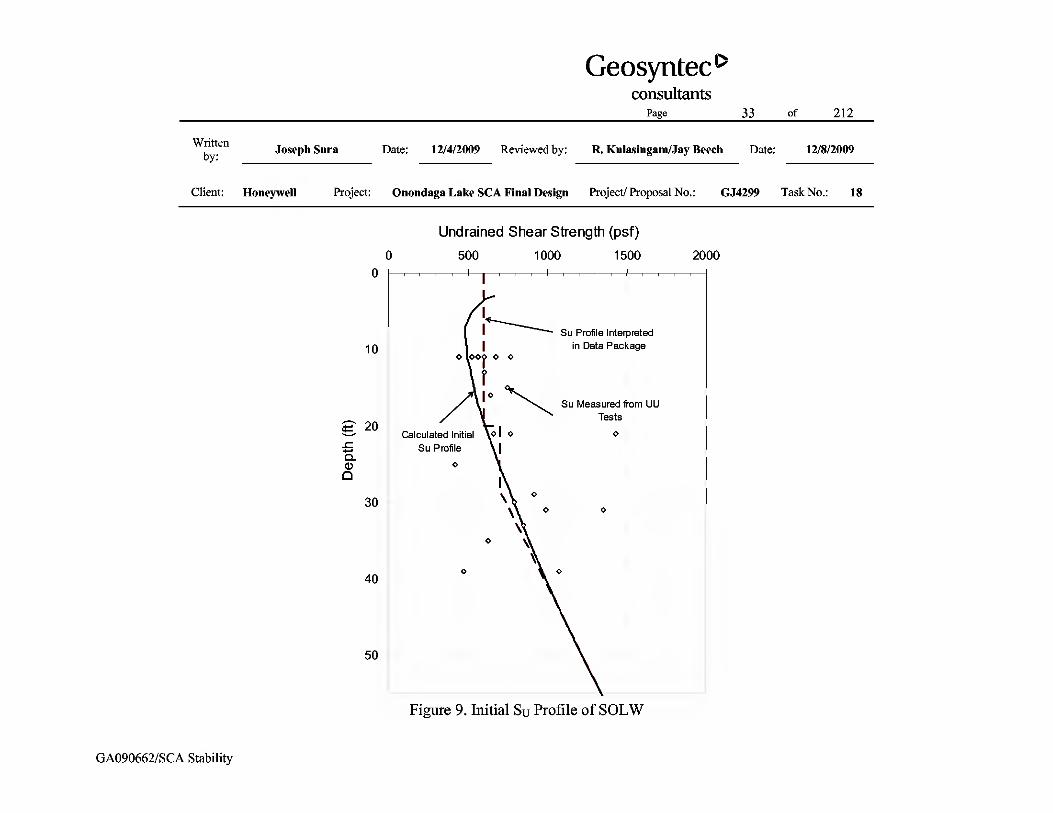
Initial Su profile: This Su profile represents the in-situ shear strength of the SOLW before construction of the SCA liner system. The Su was calculated by Equation 1 using the in-situ effective stress σv,′initial in the SOLW. The calculated initial Su profile is presented in Figure 9 along with the Su measured by the UU tests.
Su profile for Uavg = 75%: This Su profile corresponds to the shear strength of the SOLW after it achieves an average degree of consolidation (Uavg) of 75%. The Su in the SOLW at Uavg=75% (σv′75%) was calculated as a four-step process. The time factor Tv necessary to reach an average degree of consolidation of 75% is 0.477 [Das, 2005]. This time factor was used to calculate the variation of the consolidation ratio with depth (Uz) for an average consolidation ratio of Uavg=75%, as shown in Figure 10 [Lambe and Whitman, 1969]. Next, σv′75% was calculated using Equation 2.
vzinitialvv U σσσ Δ×+′= ,%75' (2)

Page 8 of 212
Written by: Joseph Sura Date: 12/4/2009 Reviewed by: R. Kulasingam/Jay Beech Date: 12/8/2009
Client: Honeywell Project: Onondaga Lake SCA Final Design Project/ Proposal No.: GJ4299 Task No.: 18
GA090662/SCA Stability
Third, the OCR at Uavg = 75% was back-calculated using the original preconsolidation pressure pc′ and the current effective stress σv′75%. Lastly, these OCR values are applied to the SHANSEP formula to derive the Su profile when the SOLW achieves Uavg=75%. Note that to calculate the Su profile for Uavg =75%, the additional effective stress ∆σv′ was based on three layers (18 ft) of dredged material in geo-tubes, 1 ft of gravel, and 1 ft of low permeability soil. The actual thicknesses of gravel and low permeability soil are greater or equal to 1 ft, however, with regards to shear strength gain, this assumption is conservative. The selection of three layers of geo-tubes as additional loading was based on the minimum number of geo-tube layers that would likely be placed the first year and the required time to consolidate, which is explained in detail below.
Su profile for Uavg = 100%: This Su profile corresponds to the shear strength of the SOLW after it reaches full consolidation under the same loading conditions as the Uavg =75% condition (i.e., three layers [18 ft] of dredged material in geo-tubes, 1 ft of gravel, and 1 ft of low permeability soil). The effective stress after consolidation was calculated using Equation 3. Due to the large additional load of the geo-tubes, the OCR for SOLW when the soil is fully consolidated was assumed to be 1.0. The SHANSEP formula was applied to calculate the final Su profile.
vinitialvv σσσ Δ+′= ,' (3)
Vertical effective stress profiles for these three stages of consolidation are shown in Figure 11. The resulting undrained shear strength profiles are shown in Figure 12.
Consolidation Rate
The time to achieve a Uavg of 75% can be calculated using Equation 4 below [Das, 2005]:
v
drv
cHT
t2
= (4)
where, vc is the coefficient of consolidation, Hdr is the 50 ft distance to the drainage layer, and Tv is the time factor based on the required degree of consolidation. For Uavg of 75%, Tv equals

Page 9 of 212
Written by: Joseph Sura Date: 12/4/2009 Reviewed by: R. Kulasingam/Jay Beech Date: 12/8/2009
Client: Honeywell Project: Onondaga Lake SCA Final Design Project/ Proposal No.: GJ4299 Task No.: 18
GA090662/SCA Stability
0.477 [Das, 2005]. Using a vc of 0.009 cm2/sec from the laboratory consolidation tests and a vc of 0.14 cm2/sec from the field test as presented in the Data Package, the time for the SOLW to achieve a Uavg of 75% was calculated to range from approximately 90 to 1420 days (3.9 years). As discussed in the Data Package, the consolidation rate in the field occurred at a much faster rate than in the lab due to lateral drainage. However, since the actual loaded area of the SCA is large enough that lateral drainage likely will not greatly affect the consolidation rate, the lab test rate of vc = 0.009 cm2/sec is considered more representative than the field test rate of actual conditions during SCA construction and operation. Therefore, it is conservatively assumed herein that the SOLW will require approximately 1420 days (3 years, 11 months) to reach the Uavg = 75% condition.
Based on the current phasing plan, the anticipated effective stress increase of the first year of construction was used to calculate the SOLW undrained shear strength at Uavg = 75%. The consolidation due to the first year of geo-tube placement will have adequate time to consolidate to be at or near a Uavg = 75% condition after placement of the final cover. However, consolidation due to years 2, 3, and 4 of geo-tube construction may not have sufficient time to reach Uavg = 75% conditions, therefore the additional strength gain from these stages of construction was conservatively ignored in calculation of the Uavg = 75% profile. Additionally, the edges of the geo-tube loaded area will not have the full ∆σv′ load calculated above. Therefore, in calculation of the Uavg = 75% profile, undrained shear strength gain in locations under the side slopes of the SCA was conservatively ignored. A potential first-year geo-tube phasing plan is shown in Figure 13.
In summary, the following items should be noted regarding the incorporation of the Su profiles into the slope stability analyses:
• The groundwater table was considered to be at 50 feet bgs (or at approximately El. 375 ft) in the calculation of the undrained shear strength. However, in the SLIDE program, the effect of the perched water zones was taken into account and modeled as a single groundwater table at 15 feet bgs as previously discussed.
• The Su profile for Uavg = 100% was not used in the analyses. The maximum undrained shear strength that the SOLW can achieve under loading was considered to be the Su profile for Uavg = 75% under three stacks of geo-tube loading.
• The initial Su profile as a function of depth was input directly into the SLIDE program and used for calculations with the exception of calculating global stability after placement of the final cover, for which the Su profile for Uavg = 75% was used.
Page 10 of 212
Written by: Joseph Sura Date: 12/4/2009 Reviewed by: R. Kulasingam/Jay Beech Date: 12/8/2009
Client: Honeywell Project: Onondaga Lake SCA Final Design Project/ Proposal No.: GJ4299 Task No.: 18
GA090662/SCA Stability
• In order to facilitate the calculations of the undrained shear strength, the initial stepwise Su profile of SOLW and the OCR profile recommended in the Data Package have been slightly modified to be smooth curves in this package.
• Due to the low permeability soil liner system, it was assumed that SOLW consolidation will occur in a single-drained state at the foundation soil layer at an average depth of 50 feet bgs.
• The computations for Uavg=75% and Uavg=100% are based on calculations of the expected required consolidation time. The actual field consolidation will be monitored through field instrumentation, and the construction will be adjusted accordingly if necessary.
ANALYZED CASES
Both Cross-Sections A-A and B-B were analyzed for conditions without the final cover and with the final cover for the four potential slip modes mentioned earlier. A more detailed discussion of the analyzed cases is presented below.
Geo-tube Slip Mode
The block slip of geo-tubes represents potential sliding within the interfaces between individual geo-tubes, resulting in multiple geo-tubes sliding off of the mass of geo-tubes. Computations were performed using short-term strength parameters, including the initial Su profile (Figure 9) to represent the undrained shear strength of the underlying SOLW layer. Since the slip surfaces do not pass through the existing SOLW, the Su values of SOLW do not affect the calculated FS. This mode was analyzed for 12 different cases for Cross-Section A-A and five different cases for Cross-Section B-B, as summarized on Tables 2 and 3, respectively. More cases were considered for Cross-Section A-A because of the higher number of vertical interfaces to be considered in that cross section, as compared to Cross-Section B-B, due to tube orientation/geometry. The number of stacks indicated in the tables represents the tiers, counting from the top downwards, involved in the potential slip. The number of columns represents the number of geo-tubes per stack involved in the potential slip. A conceptual illustration of “stacks” and “columns” is shown in Figure 14.
As indicated previously, establishing a range in friction angles that would be considered acceptable for the geo-tube/geo-tube interface is also a goal of the stability analyses presented herein. Therefore, based on the initial analyses using the friction angles established through laboratory testing, which yielded acceptable FS values, the most critical case for geo-tube slip

Page 11 of 212
Written by: Joseph Sura Date: 12/4/2009 Reviewed by: R. Kulasingam/Jay Beech Date: 12/8/2009
Client: Honeywell Project: Onondaga Lake SCA Final Design Project/ Proposal No.: GJ4299 Task No.: 18
GA090662/SCA Stability
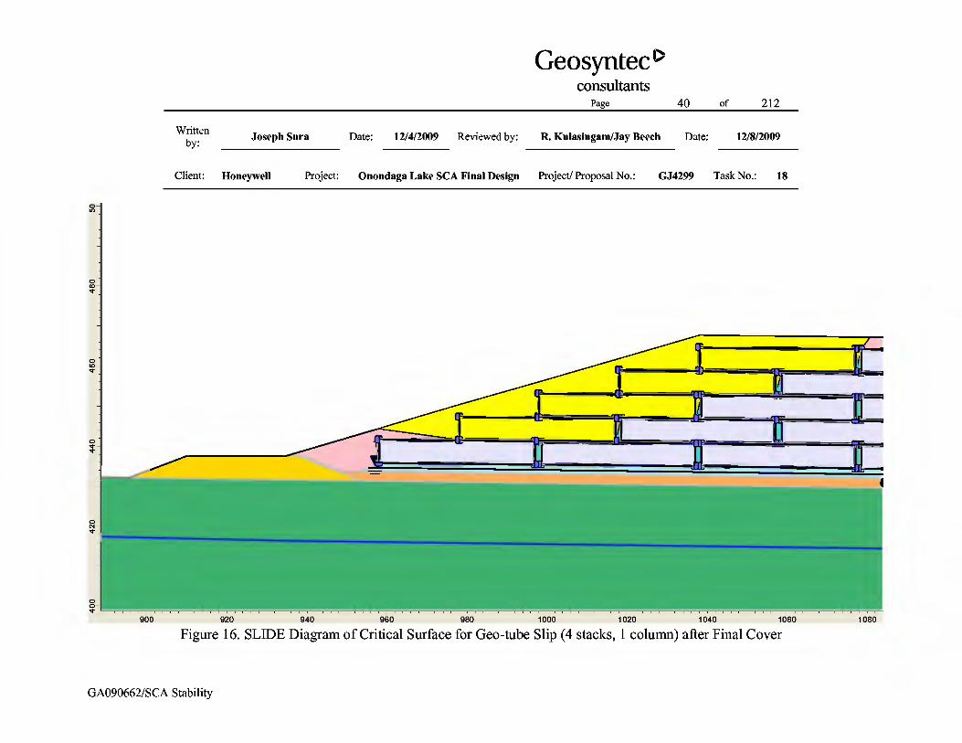
was identified (i.e., Top 4 stacks; 1 column, as indicated on Table 2). This critical case is illustrated in Figure 15 without a final cover and in Figure 16 with a final cover.
In addition, this critical case was used to back-calculate the required effective stress friction angle of the horizontal geo-tube/geo-tube interface to achieve the target FS for both peak and residual conditions. This procedure was followed for Cross-Section A-A without the final cover (target peak FS=1.3, target residual FS=1.1) and for Cross-Section A-A with the final cover (target peak FS=1.5, target residual FS=1.3). Since the geo-tube slip mode is more critical for Cross-Section A-A due to the geometry involved (see results on Table 2 as compared to 3), the back-calculated values from Cross-Section A-A are also considered acceptable for Cross-Section B-B. This is discussed in more detail in Attachment 4.
Liner Stability
Block slip of the liner represents sliding along the proposed liner. Computations using this mode were performed using short-term strength parameters and the initial Su profile (Figure 9) to represent the undrained shear strength of the SOLW layer. Since the slip surfaces do not pass through the existing SOLW, these Su values do not affect the calculated FS.
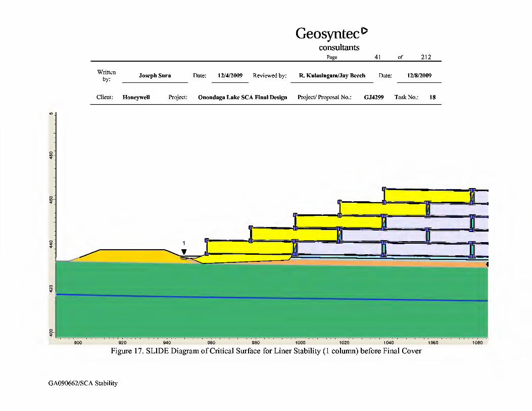
Similar to the geo-tube slip mode analysis, first the most critical case for liner stability was identified using the minimum friction angle established during laboratory testing. For liner stability, the critical case involves the liner failing underneath the first column of geo-tubes, as illustrated in Figures 17 and 18 without and with final cover, respectively. Once the critical case was identified, the analysis was also performed using the maximum laboratory measured liner friction angle. Table 2 provides the results using the minimum liner friction angle established in the laboratory testing, and Attachment 3 provides the results (critical case only) using the maximum liner friction angle established in the laboratory testing.
As indicated previously, establishing a range in friction angles that would be considered acceptable for the liner system is also a goal of the stability analyses. Using the critical case identified above, the required effective stress friction angle of the proposed liner system to achieve the target FS could be back-calculated. To establish a range in friction angle values, the sensitivity of the liner friction angle to changes in the geo-tube/geo-tube horizontal interface friction angle was also evaluated. The geo-tube/geo-tube horizontal interface friction angle was changed, and the required liner friction angle to achieve the target FS against liner slip was back-calculated using SLIDE. Based on the results presented in Tables 2 and 3, the Cross-Section A-A geometry is considered to be more critical than the Cross-Section B-B geometry; therefore, the additional analyses were performed on Cross-Section A-A. The results of these calculations before and after placement of the final cover are shown and discussed further in Attachment 4.

Page 12 of 212
Written by: Joseph Sura Date: 12/4/2009 Reviewed by: R. Kulasingam/Jay Beech Date: 12/8/2009
Client: Honeywell Project: Onondaga Lake SCA Final Design Project/ Proposal No.: GJ4299 Task No.: 18
GA090662/SCA Stability
Global Stability (Circular slip surfaces)
Global stability of the proposed SCA was evaluated with circular potential slip surfaces. The global stability through the foundation material prior to placement of the final cover was evaluated using undrained strength parameters (the initial Su profile shown in Figure 9) to represent the undrained shear strength of the SOLW layer. The global stability after placement of the final cover was evaluated for three cases: (i) Interim stability with the initial Su profile; (ii) Interim stability with Uavg=75%; and (iii) Long-term stability.
The interim global stability case immediately after placement of the final cover was evaluated using the initial Su profile to represent the undrained shear strength of the SOLW layer. The interim global stability case immediately after placement of the final cover was also evaluated using the Su profile after consolidation to Uavg=75% to represent the undrained shear strength of the SOLW layer.
The long-term global stability after cover placement was evaluated using drained strength parameters. This long-term global stability evaluation was performed by assuming that the geotextile support of the geo-tubes will be degraded and therefore have no shear strength. The long-term evaluation was performed by also assuming the effective stress friction angle of the dredge material will increase to 30 degrees due to consolidation of the material (i.e., the long-term value provided in Table 1).
Global Stability of WB-13 Perimeter Dikes (Circular slip surfaces)
Potential global stability for slip surfaces through the SCA and existing WB-13 perimeter dike was evaluated for Cross-Sections A-A and B-B. This slip mode was analyzed for three cases: (i) Interim stability before final cover placement; (ii) Interim stability after final cover placement; and (iii) Long-term global stability.
In addition, global stability of the WB-13 perimeter dike was considered by focusing on potential slip surfaces through the dike. For these analyses, the WB-13 perimeter dike was modeled with a 2-ft thick crusty surficial layer with a cohesion intercept of 50 psf and a friction angle of 37 degrees to represent the effects of desiccation and roots. The inner portion of the WB-13 perimeter dike was modeled only with a friction angle of 37 degrees, consistent with the other cases analyzed. Two cases were considered to model the groundwater table within the WB-13 perimeter dike. The first case considered a water table that varies from the conservatively assumed 15 feet below ground level at the dike-SOLW interface to the ground surface level at the toe of the dike. The second case considered a water table that varies from 15 feet below ground level at the dike-SOLW interface to a level at the outside dike face that is 10 feet above the ground surface level at the toe of the dike.

Page 13 of 212
Written by: Joseph Sura Date: 12/4/2009 Reviewed by: R. Kulasingam/Jay Beech Date: 12/8/2009
Client: Honeywell Project: Onondaga Lake SCA Final Design Project/ Proposal No.: GJ4299 Task No.: 18
GA090662/SCA Stability
RESULTS AND DISCUSSION
Slope Stability Analysis
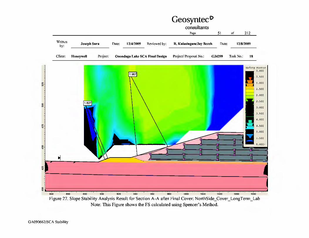
The results of the slope stability analyses for Cross-Sections A-A and B-B are summarized in Tables 2, 3, and 4. The results of the analyses for the most important cases are also shown graphically in Figures 19 through 43. The associated SLIDE runs are presented in Attachment 5 of this package.
The calculation results for Cross-Section A-A are summarized in Table 2 and indicate that the calculated FS values for cases without and with the final cover satisfy the target FS of 1.3 and 1.5, respectively, for the geo-tube slip mode, liner stability, and global stability. Since the global stability case using the initial Su profile achieved the interim FS=1.3 criterion, a check of global stability using the Uavg = 75% profile was not performed for Cross-Section A-A.
The calculation results for Cross-Section B-B are summarized in Table 3 and indicate that the calculated FS values for cases without and with the final cover satisfy the target FS of 1.3 and 1.5, respectively, for the slip modes evaluated (i.e., geo-tubes slip mode, liner stability, and global stability). Slope stability analyses performed to evaluate a potential global slip mechanism resulted in a calculated FS satisfying the interim target FS of 1.3 using the initial Su profile. It is noted that the actual Su profile will be greater than the initial due to consolidation of the foundation soils under the loading from the geo-tubes. When the Uavg = 75% Su profile is used, the calculated FS is greater than when the initial Su profile is used. The calculated FS for long-term global stability satisfies the target FS of 1.5.
Slope stability analyses performed to evaluate the potential global slip mechanisms through the SCA and existing WB-13 perimeter dikes resulted in FS values much greater than the target FS. Cross-Section A-A, as expected, has a lower factor of safety than for Cross-Section B-B with regards to global slip of existing WB-13 perimeter dikes, however, the calculated FS for Cross-Section A-A still greatly exceeds the target FS for both interim and long-term conditions.
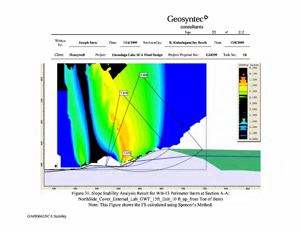
Slope stability analyses were also performed for slip surfaces through the WB-13 perimeter dike that do not extend to the SCA (i.e., analyses focused on the dike only). For the case with the water table at the toe of the dike, minimum FS values of 3.0 for the critical global slip surface extending to the top of the WB-13 perimeter dike and 1.8 for the critical shallow slip surface within the slope were calculated, as shown in Figure 30. For the case with the water table at 10 feet above the toe of the dike, minimum FS values of 1.8 for the critical global slip surface extending to the top of the WB-13 perimeter dike and 1.1 for the critical shallow slip surface within the slope were calculated, as shown in Figure 31. This shallow slip surface is located near the toe under the estimated water table level within the WB-13 perimeter dike. A FS of 1.1 for
Page 14 of 212
Written by: Joseph Sura Date: 12/4/2009 Reviewed by: R. Kulasingam/Jay Beech Date: 12/8/2009
Client: Honeywell Project: Onondaga Lake SCA Final Design Project/ Proposal No.: GJ4299 Task No.: 18
GA090662/SCA Stability
shallow slip surfaces is indicative of the potential for surficial sloughing. Since dike stability is directly related to water level (i.e., pore water pressure) within the dike, it is recommended that instrumentation and monitoring be performed during operations, and remedial measures be implemented if appropriate.
FS values were also calculated using residual shear strengths for the geosynthetic components. For Cross-Section A-A, the critical geo-tube slip case of one column of four stacks of geo-tubes and the critical liner slip case of one column of geotubes before and after final cover placement were evaluated. The calculated FS values using residual shear strengths satisfy the target residual FS values for both interim and long-term conditions.
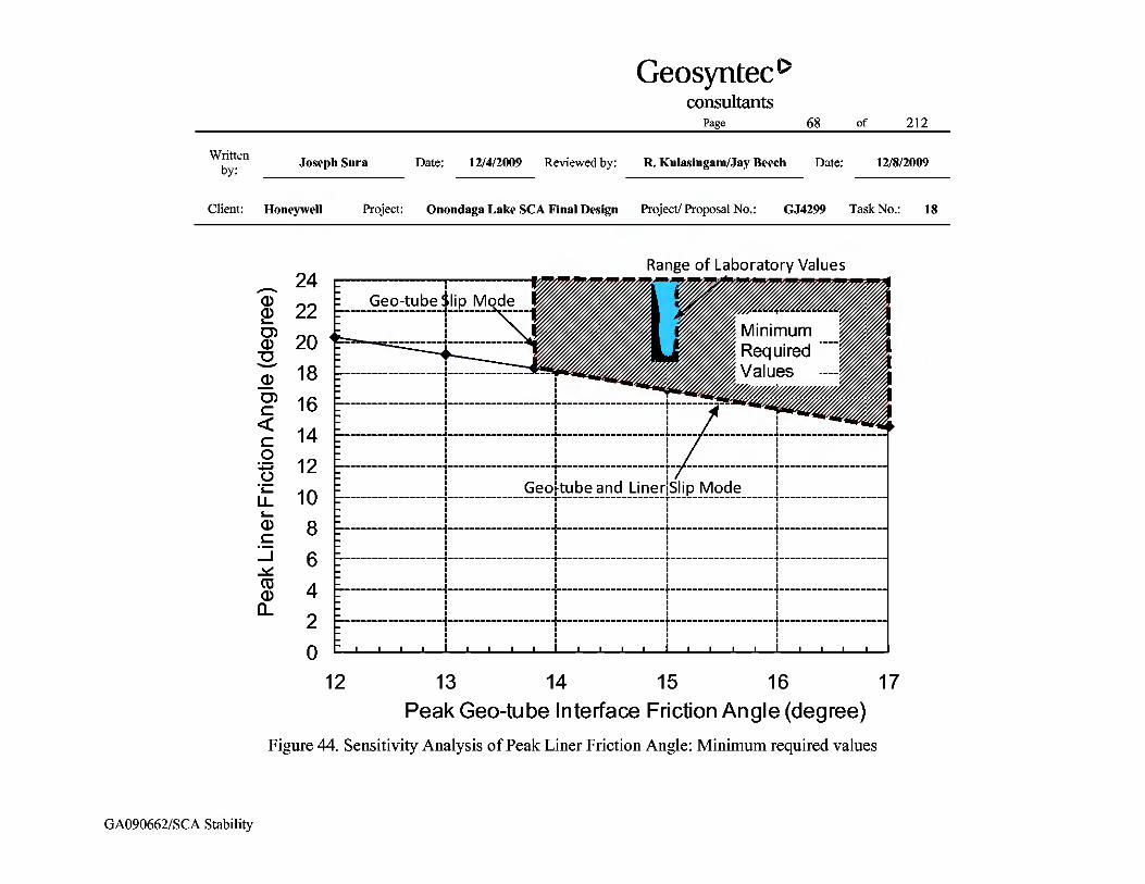
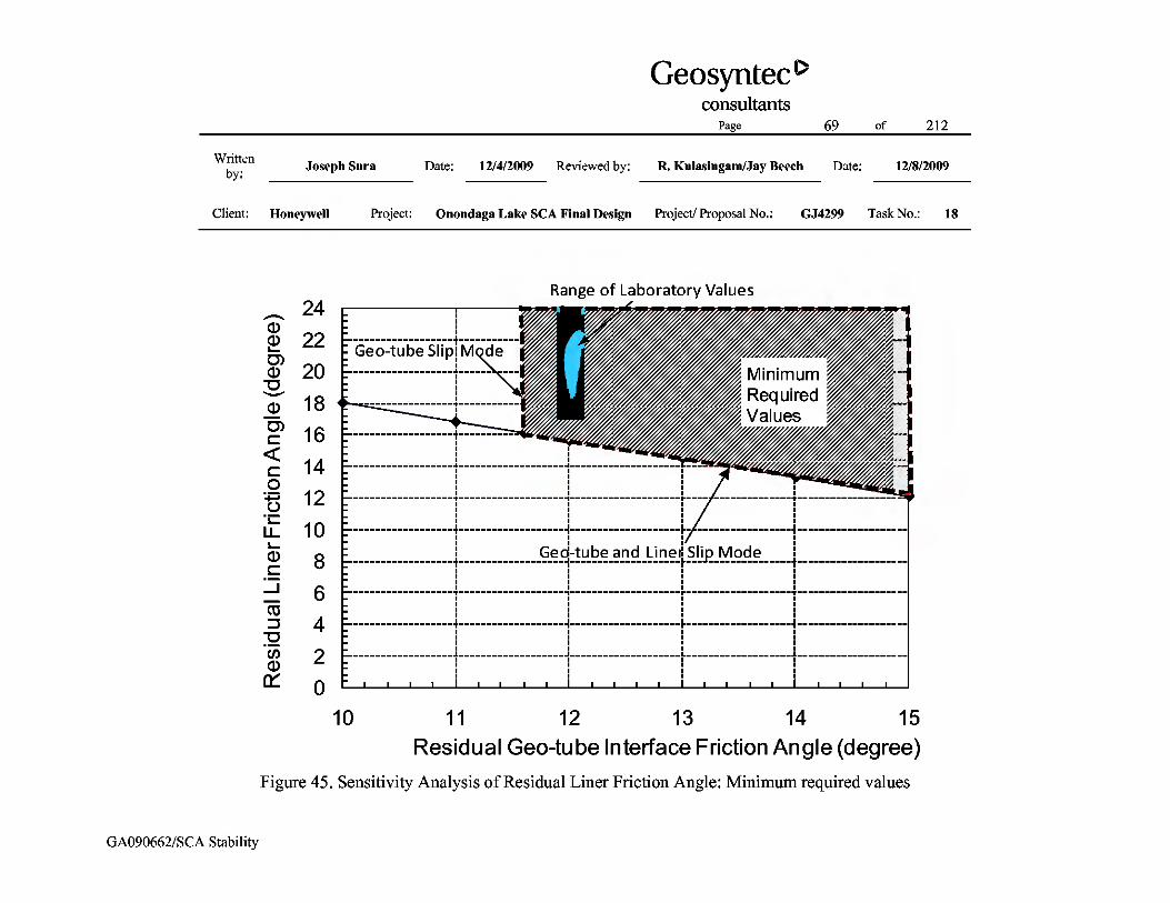
Additionally, the back-calculation presented in Attachment 4 indicates that the required values for the peak laboratory friction angles for the horizontal geo-tube/geo-tube interface and liner system are 13.8 degrees and 18.3 degrees, respectively (or alternative combinations as shown in Figure 44), to meet the target FS values. The required values for the residual laboratory friction angles for the horizontal geo-tube/geo-tube interface and liner system are 11.6 degrees and 16.1 degrees, respectively (or alternative combinations as shown in Figure 45), to meet the target FS values. The minimum required values of peak and residual effective stress friction angle to meet the target FS values are shown in Figures 44 and 45. It is recommended that site-specific testing be performed on the selected liner system to verify the strength parameters meet or exceed these back-calculated values.
SUMMARY AND CONCLUSIONS
This package evaluates the static slope stability of the proposed SCA. Four potential slip modes were evaluated using the computer computation program SLIDE: (i) block slip mode along geo-tube interfaces; (ii) block slip mode along the liner system, (iii) circular slip surfaces through dredge material contained in geo-tubes and WB-13 foundation materials; and (iv) circular slip surfaces through existing WB-13 perimeter dikes.
Analyses of two critical cross-sections indicate that the calculated FSs for the four potential slip modes meet the target FS for interim and long-term conditions. However, placement of five layers of geo-tubes and the final cover system within the same season results in a calculated FS that only slightly exceeds the target value, a limitation that should be considered during design of the phasing plan for geo-tube construction. Instrumentation to monitor the field consolidation is recommended to verify adequate strength gain occurs before placement of the final cover. In addition, piezometers to monitor the water levels in the dikes, and inclinometers near the SCA berms to monitor stability in the field are recommended. Details regarding this instrumentation
Page 15 of 212
Written by: Joseph Sura Date: 12/4/2009 Reviewed by: R. Kulasingam/Jay Beech Date: 12/8/2009
Client: Honeywell Project: Onondaga Lake SCA Final Design Project/ Proposal No.: GJ4299 Task No.: 18
GA090662/SCA Stability
are provided in Appendix N of the SCA Final Design, “Geotechnical Instrumentation and Monitoring Plan.”
Minimum required parameters for the interface between geo-tubes and the liner system have been back-calculated. In order to meet the target factor of safety values against block slip, the peak effective stress friction angle for the interface between geo-tubes should be at least 13.8 degrees and the peak effective stress friction angle for the liner system should be at least 18.1 degrees. In order to meet the target factor of safety values against block slip, the residual effective stress friction angle for the interface between geo-tubes should be at least 11.6 degrees and the peak effective stress friction angle for the liner system should be at least 16.1 degrees. Alternative combinations of geo-tube friction angle and liner friction angle may also be acceptable, as shown in Figures 44 and 45. Laboratory testing indicates that these values are achievable with a variety of common commercially available geosynthetics. Testing of material delivered to the project during construction will be performed to verify components meet the specified strength.

Page 16 of 212
Written by: Joseph Sura Date: 12/4/2009 Reviewed by: R. Kulasingam/Jay Beech Date: 12/8/2009
Client: Honeywell Project: Onondaga Lake SCA Final Design Project/ Proposal No.: GJ4299 Task No.: 18
GA090662/SCA Stability
REFERENCES
Bishop, A., “The Use of the Slip Circle in the Stability Analysis of Slopes,” Geotechnique, Volume 5, No. 1, Jan 1955, pp. 7-17.
Das, B.M., Fundamentals of Geotechnical Engineering, Second Edition, Thomson, 2005. Geosynthetic Research Institute (GRI), “Determination of the Long-Term Design Strength of
Geotextiles”, Folsom, PA, 1992. Hammer, D.P., and Blackburn, E.D. , “Design and Construction of Retaining Dikes for
Containment of Dredged Material”, Technical Report D-77-9, U.S. Army Engineer Water Experiment Station, Vicksburg, Mississippi, August 1977, pp. 93.
Janbu, N., “Slope Stability Computations,” Embankment Dam Engineering, Casagrande
Memorial Volume, R. C. Hirschfield and S. J. Poulos, Eds., John Wiley, New York, 1973, pp. 47-86.
Koerner, R.M., Design with Geosynthetics, Third Edition, Prentice Hall, Upper Saddle River,
N.J. 1994. Ladd, C. C. and DeGroot, D. J., “Recommended Practices for Soft Ground Site Characterization:
Arthur Casagrande Lecture,” Proceedings of the 12th Pan American Conference on Soil Mechanics and Geotechnical Engineering, Massachusetts Institute of Technology, Cambridge, Massachusetts, June 2003.
Ladd, C. C and Foott, R., “New Design Procedure for Stability of Soft Clays.” Journal of the
Geotechnical Engineering Division, American Society of Civil Engineers, Vol. 100, No. GT7, July 1974.
Lambe, T.W. and Whitman, R.V., Soil Mechanics, John Wiley & Sons, New York, 1969. Petersen, M.D. et. al., “Documentation for the 2008 Update of the United States National Seismic Hazard Maps: U.S. Geological Survey Open-File Report 2008–1128”, U.S. Geological Survey, Reston, VA, 2008.

Page 17 of 212
Written by: Joseph Sura Date: 12/4/2009 Reviewed by: R. Kulasingam/Jay Beech Date: 12/8/2009
Client: Honeywell Project: Onondaga Lake SCA Final Design Project/ Proposal No.: GJ4299 Task No.: 18
GA090662/SCA Stability
Rocscience, “SLIDE – 2-D Limit Equilibrium Slope Stability for Soil and Rock Slopes,” User's Guide, Rocscience Software, Inc., Toronto, Ontario, Canada, 2009.
Spencer, E., “The Thrust Line Criterion in Embankment Stability Analysis,” Géotechnique, Vol. 23, No. 1, pp. 85-100, March 1973. U.S. Army Corps of Engineers (USACE), “Engineering and Design – Slope Stability”,
Engineering Manual EM 1110-2-1902, October 2003, pp. 3-2.

Page 18 of 212
Written by: Joseph Sura Date: 12/4/2009 Reviewed by: R. Kulasingam/Jay Beech Date: 12/8/2009
Client: Honeywell Project: Onondaga Lake SCA Final Design Project/ Proposal No.: GJ4299 Task No.: 18
GA090662/SCA Stability
Tables

Page 19 of 212
Written by: Joseph Sura Date: 12/4/2009 Reviewed by: R. Kulasingam/Jay Beech Date: 12/8/2009
Client: Honeywell Project: Onondaga Lake SCA Final Design Project/ Proposal No.: GJ4299 Task No.: 18
GA090662/SCA Stability
Table 1. Summary of Material Properties for Slope Stability Analysis
Material Unit Weight (pcf)
Undrained Shear Strength (psf)
Drained Shear Strength Effective Stress Friction Angle (degree)
SOLW 82 See Figures 7 through 12 34 SCA Perimeter Dike Soil 120 --- 35
Foundation Soil (including WB-13
perimeter dike) 120 --- 37
Liner 100 --- 19[1] Gravel Drainage 120 --- 38 Geo-tube/Gravel
Interface 86 --- 24[2]
Geo-tube --- Design Tensile Strength = 1600 lb/ft[3] Dredge Material (Short
Term) 86 --- 15[4]
Dredge Material (Long-Term) 86 --- 30
Geo-tube/Geo-tube Interface (Vertical) 43[5] --- 0.1[6]
Geo-tube/Geo-tube Interface (Horizontal) 86 --- 15[1]
Final Cover Soil 120 --- 30

Page 20 of 212
Written by: Joseph Sura Date: 12/4/2009 Reviewed by: R. Kulasingam/Jay Beech Date: 12/8/2009
Client: Honeywell Project: Onondaga Lake SCA Final Design Project/ Proposal No.: GJ4299 Task No.: 18
GA090662/SCA Stability
Table 1. Summary of Material Properties for Slope Stability Analysis (Continued)
Notes: 1. The values presented in this table (i.e., 15 degrees and 19 degrees) are the measured peak effective friction angles for geo-tube/geo-tube interface and liner,
respectively (see Attachment 2). 2. Taken from Koerner [1994]. A typical value of interface effective friction angle between woven geotextile and sand was assumed. 3. The design tensile strength was modeled using a two-end anchored geotextile sheet. Based on commercially available products, the ultimate tensile strength
of geo-tubes was assumed to be 4800 lb/ft and a strength reduction factor of 3.0 was applied to calculate the design tensile strength, taking into account creep deformation, chemical degradation, and strength loss within seams, connections, and joints [GRI, 1992].
4. Under short-term conditions, the dredge material was assumed to have half of the friction angle of the material under long-term conditions. 5. The vertical interface was assumed to have a unit weight equal to half of the unit weight of the dredge material. This was based on the geometry of the geo-
tubes after deformation. The volume of material in the vertical interface after deformation was assumed to be approximately half the total volume available if the geo-tubes could be placed in direct contact with each other along the entire interface.
6. The geo-tube/geo-tube vertical interface has insignificant side friction, but a small value of friction angle was necessary for numerical stability of the SLIDE calculation program.

Page 21 of 212
Written by: Joseph Sura Date: 12/4/2009 Reviewed by: R. Kulasingam/Jay Beech Date: 12/8/2009
Client: Honeywell Project: Onondaga Lake SCA Final Design Project/ Proposal No.: GJ4299 Task No.: 18
GA090662/SCA Stability
Table 2. Summary of Slope Stability Analysis: Cross-Section A-A
Case Without Final Cover With Final Cover
Calculated FS[1]
Figure Number
Target F.S.
Calculated FS[1] Figure Number
Target F.S. Spencer's
Method[2] Janbu's Method[2]
Spencer's Method[2]
Janbu's Method[2]
Slip of Geo‐tubes (Block Mode)
Top 1 stack; 1 column ‐‐ 8.53 ‐‐ 1.30 ‐‐ 8.68 ‐‐ 1.50
Top 1 stack; 2 columns ‐‐ 26.71 ‐‐ 1.30 ‐‐ ‐‐ [5] ‐‐ ‐‐
Top 2 stacks; 1 column ‐‐ 2.44 ‐‐ 1.30 ‐‐ 3.37 ‐‐ 1.50
Top 2 stacks; 2 columns ‐‐ 5.40 ‐‐ 1.30 ‐‐ ‐‐ [5] ‐‐ ‐‐
Top 3 stacks; 1 column ‐‐ 1.73 ‐‐ 1.30 ‐‐ 2.02 ‐‐ 1.50
Top 3 stacks; 2 columns ‐‐ 3.50 ‐‐ 1.30 ‐‐ 3.81 ‐‐ 1.50
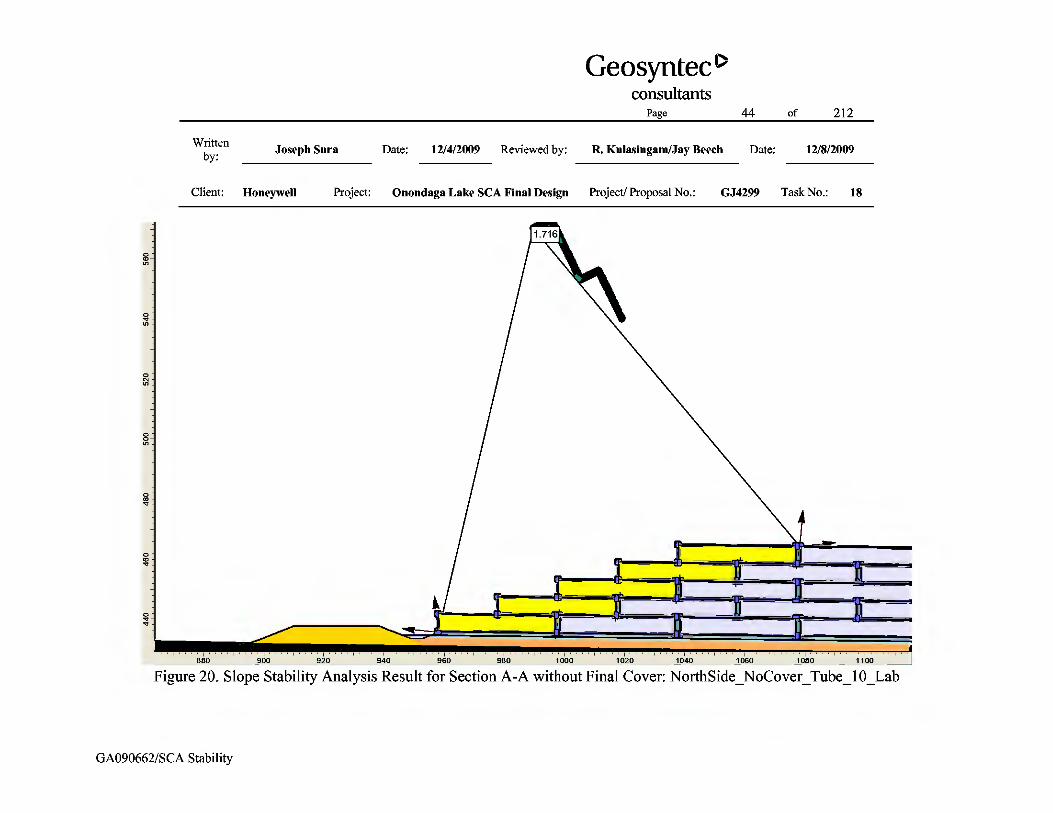
Top 4 stacks; 1 column ‐‐ 1.52 19 1.30 ‐‐ 1.62 24 1.50
Top 4 stacks; 2 columns ‐‐ 2.44 ‐‐ 1.30 ‐‐ 2.79 ‐‐ 1.50
Top 4 stacks; 3 columns ‐‐ 3.89 ‐‐ 1.30 ‐‐ ‐‐ [5] ‐‐ ‐‐
5 stacks; 1 column ‐‐ 1.72 20 1.30 ‐‐ 1.73 ‐‐ 1.50
5 stacks; 2 columns ‐‐ 2.69 ‐‐ 1.30 ‐‐ 2.89 ‐‐ 1.50
5 stacks; 3 columns ‐‐ 4.47 ‐‐ 1.30 ‐‐ ‐‐ [5] ‐‐ ‐‐
Liner Stability (Block Mode)
One column of geo‐tubes ‐‐ 1.57 21 1.30 ‐‐ 1.59 25 1.50
Two columns of geo‐tubes ‐‐ 2.24 ‐‐ 1.30 ‐‐ 2.48 ‐‐ 1.50
Global Stability (Circular Mode)
Through Foundation Material (Uavg=0%) – Interim
1.66 [3] ‐‐ 22 1.30 1.45 [3] ‐‐ 26 1.30
Through Foundation Material (Uavg=75%) – Interim
‐‐ ‐‐ ‐‐ ‐‐ ‐‐[6] ‐‐[6] ‐‐ ‐‐
Through Foundation Material – Long‐Term
‐‐ ‐‐ ‐‐ ‐‐ 1.83[7] ‐‐ 27 1.50
Global Stability (Circular Mode)
Through SCA and Existing WB‐13 Perimeter Dike – Interim
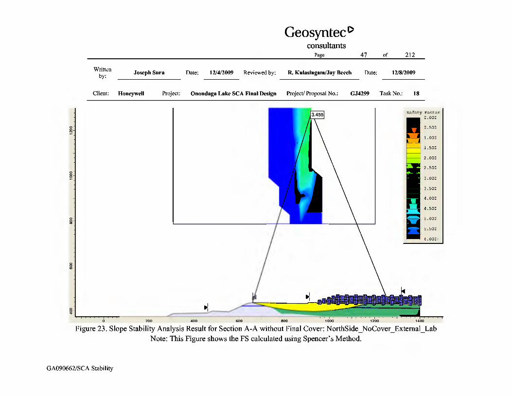
3.46 [4] ‐‐ 23 1.30 2.84[4] ‐‐ 28 1.30
Through SCA and Existing WB‐13 Perimeter Dike – Long Term
‐‐ ‐‐ ‐‐ ‐‐ 5.65 ‐‐ 29 1.50

Page 22 of 212
Written by: Joseph Sura Date: 12/4/2009 Reviewed by: R. Kulasingam/Jay Beech Date: 12/8/2009
Client: Honeywell Project: Onondaga Lake SCA Final Design Project/ Proposal No.: GJ4299 Task No.: 18
GA090662/SCA Stability
Table 2. Summary of Slope Stability Analysis: Cross-Section A-A (Continued) Notes: 1. These values are calculated using the laboratory values of peak effective stress friction angle for the geo-tube/geo-tube horizontal interface (15 degrees) and the liner (19 degrees). The laboratory test data are shown in Figures 2-4 and 2-5 of Attachment 2. 2. Spencer’s method is considered more rigorous than Janbu’s method because Spencer’s method satisfies both force and moment equilibrium. However, Spencer's method often encounters numerical convergence difficulty when complicated block slip surfaces are
considered, as in this analysis. Therefore, Spencer's method was used for the circular mode analysis, while Janbu's method was used for the block mode analysis 3. This calculation uses the initial Su profile for the undrained shear strength of the existing SOLW. 4. This was modeled by forcing the slip circle to pass through the existing WB-13 perimeter dike. 5. This case was not analyzed due to the acceptable FS values found for similar cases. 6. The Uavg=75% case was not analyzed for Cross-Section A-A because the interim FS was acceptable using the initial Su profile. 7. For long-term, the geotextile of the geo-tubes was assumed to be degraded and therefore have no shear strength. The dredge material was modeled with the long-term friction angle of 30 degrees. 8. Figures are only included for the most important cases.

Page 23 of 212
Written by: Joseph Sura Date: 12/4/2009 Reviewed by: R. Kulasingam/Jay Beech Date: 12/8/2009
Client: Honeywell Project: Onondaga Lake SCA Final Design Project/ Proposal No.: GJ4299 Task No.: 18
GA090662/SCA Stability
Table 3. Summary of Slope Stability Analysis: Cross-Section B-B
Case
Without Final Cover With Final Cover
Calculated FS[1] Figure Number
Target F.S.
Calculated FS[1] Figure Number
Target F.S. Spencer's
Method[2] Janbu's Method[2]
Spencer's Method[2]
Janbu's Method[2]
Slip of Geo‐tubes[3] (Block Mode)
Top 1 stack; 1 column ‐‐ 46.93 ‐‐ 1.30 ‐‐ 21.73 ‐‐ 1.50
Top 2 stacks; 1 column ‐‐ 13.47 ‐‐ 1.30 ‐‐ 10.66 ‐‐ 1.50
Top 3 stacks; 1 column ‐‐ 10.73 ‐‐ 1.30 ‐‐ 9.04 ‐‐ 1.50
Top 4 stacks; 1 column ‐‐ 6.60 32 1.30 ‐‐ 6.00 37 1.50
5 stacks; 1 column ‐‐ 9.81 33 1.30 ‐‐ 9.30 ‐‐ 1.50
Liner Stability[3]
(Block Mode) One column of geo‐tubes ‐‐ 1.86 34 1.30 ‐‐ 1.81 38 1.50
Global Stability (Circular Mode)
Through Foundation Material (Uavg=0%) – Interim
1.36[3] ‐‐ 35 1.30 1.40[3] ‐‐ 39 1.30
Through Foundation Material (Uavg=75%) – Interim
‐‐ ‐‐ ‐‐ ‐‐ 1.42[4] ‐‐ 40 1.30
Through Foundation Material – Long‐Term[5]
‐‐ ‐‐ ‐‐ ‐‐ 1.91 ‐‐ 41 1.50
Global Stability (Circular Mode)
Through SCA and Existing WB‐13 Perimeter Dike – Interim
8.39 ‐‐ 36 1.30 7.07 ‐‐ 42 1.30
Through SCA and Existing WB‐13 Perimeter Dike – Long‐Term
‐‐ ‐‐ ‐‐ ‐‐ 11.96 ‐‐ 43 1.50
Notes: 1. These values are calculated using the laboratory values of peak effective stress friction angle for the geo-tube/geo-tube horizontal interface (15 degrees) and the liner (19 degrees). The laboratory test data are shown in Figures 2-4 and 2-5 of Attachment 2. 2. Spencer's method is considered more rigorous than Janbu's method because Spencer's method satisfies both force and moment equilibrium. However, Spencer's method often encounters numerical convergence difficulty when complicated block slip surfaces are
considered, as in this analysis. Therefore, Spencer's method was used for the circular mode analysis, while Janbu's method was used for the block mode analysis. 3. This calculation uses the initial Su profile for the undrained shear strength of the existing SOLW. 4. This calculation uses the Uavg=75% profile for the undrained shear strength of the existing SOLW under the gravel, liner system, and three layers of geo-tubes. 5. For long-term, the geotextile of the geo-tubes was assumed to be degraded and therefore have no shear strength. The dredge material uses the long-term friction angle of 30 degrees. 6. Figures are only included for the most important cases.

Page 24 of 212
Written by: Joseph Sura Date: 12/4/2009 Reviewed by: R. Kulasingam/Jay Beech Date: 12/8/2009
Client: Honeywell Project: Onondaga Lake SCA Final Design Project/ Proposal No.: GJ4299 Task No.: 18
GA090662/SCA Stability
Table 4. Summary of Slope Stability Analysis: Residual Conditions for Cross-Section A-A
Case
Without Final Cover (Interim) With Final Cover (Long-Term)
Calculated FS[1] Target FS
Calculated FS[1] Target FS
Janbu's Method[2] Janbu's Method[2]
Slip of Geotubes (Block Mode) Top 4 stacks; 1 column 1.21 1.10 1.34 1.30
Liner Stability (Block Mode) One column of geo-tubes 1.33 1.10 1.36 1.30
Notes: 1. These values are calculated using the laboratory values of residual effective stress friction angle for the geo-tube/geo-tube horizontal interface (12 degrees) and the liner (17 degrees). The laboratory test data are shown in Figures 2-2 and 2-5 of Attachment 2. 2. The Janbu method was used for the block mode analyses presented here because Spencer's method often encounters numerical convergence difficulty with these types of analyses. 3. The target residual FS is 1.1 for the interim condition and 1.3 for long-term conditions.

Page 25 of 212
Written by: Joseph Sura Date: 12/4/2009 Reviewed by: R. Kulasingam/Jay Beech Date: 12/8/2009
Client: Honeywell Project: Onondaga Lake SCA Final Design Project/ Proposal No.: GJ4299 Task No.: 18
GA090662/SCA Stability
Figures


Page 70 of 212
Written by: Joseph Sura Date: 12/4/2009 Reviewed by: R. Kulasingam/Jay Beech Date: 12/8/2009
Client: Honeywell Project: Onondaga Lake SCA Final Design Project/ Proposal No.: GJ4299 Task No.: 18
GA090662/SCA Stability
Attachment 1 Seismic Impact Zone

Page 71 of 212
Written by: Joseph Sura Date: 12/4/2009 Reviewed by: R. Kulasingam/Jay Beech Date: 12/8/2009
Client: Honeywell Project: Onondaga Lake SCA Final Design Project/ Proposal No.: GJ4299 Task No.: 18
GA090662/SCA Stability
NYSDEC Regulations Section 360-2.7(b)(7) states that a seismic analysis is required “for new landfills, lateral expansions of existing landfills, and subsequent development of any landfill permitted pursuant to these provisions located in a seismic impact zone.” The seismic impact zone is defined as “an area with a 10 percent or greater probability that the maximum horizontal acceleration in lithified earth material, expressed as a percentage of the earth's gravitational pull (g), will exceed 0.10g in 250 years.”
According to the 2008 USGS National Seismic Hazard Map [Petersen et al, 2008], the SCA site falls within an area characterized by a peak ground acceleration (i.e., maximum horizontal acceleration in lithified earth material) of 0.0784g with 2 percent probability of exceedance in 50 years, which is approximately equivalent to 10 percent of exceedance in 250 years. The USGS Seismic Hazard Curves and Uniform Response Spectra computer analysis program was also used to calculate the peak ground acceleration with 10 percent of exceedance in 250 years directly, resulting in an estimated peak ground acceleration of 0.0765g. Table 1-1 presents the peak ground accelerations based on the site location, as calculated by the software, and Figure 1-1 shows the location of the SCA on the USGS National Seismic Hazard Map.
Therefore, based on the maximum horizontal acceleration, the SCA is not located in a seismic impact zone as defined by NYSDEC Regulations. As a result, a seismic slope stability analysis is not required.

Page 72 of 212
Written by: Joseph Sura Date: 12/4/2009 Reviewed by: R. Kulasingam/Jay Beech Date: 12/8/2009
Client: Honeywell Project: Onondaga Lake SCA Final Design Project/ Proposal No.: GJ4299 Task No.: 18
GA090662/SCA Stability
Table 1-1. Peak Ground Accelerations Based on SCA Site Location
Hazard Curve for PGA, Latitude = 43.0600, Longitude = -76.2500
PGA (%g) %PE Time 7.84 2% 50 years 7.65 10% 250 years
Seismic Hazard Curves and Uniform Response Spectra. USGS, October 2008.

Page 73 of 212
Written by: Joseph Sura Date: 12/4/2009 Reviewed by: R. Kulasingam/Jay Beech Date: 12/8/2009
Client: Honeywell Project: Onondaga Lake SCA Final Design Project/ Proposal No.: GJ4299 Task No.: 18
GA090662/SCA Stability
Figure 1-1. Location of the SCA on the USGS National Seismic Hazard Map
Location of SCA

Page 74 of 212
Written by: Joseph Sura Date: 12/4/2009 Reviewed by: R. Kulasingam/Jay Beech Date: 12/8/2009
Client: Honeywell Project: Onondaga Lake SCA Final Design Project/ Proposal No.: GJ4299 Task No.: 18
GA090662/SCA Stability
Attachment 2 Interface Direct Shear Testing
(Results provided to Geosyntec by Parsons)

Page 75 of 212
Written by: Joseph Sura Date: 12/4/2009 Reviewed by: R. Kulasingam/Jay Beech Date: 12/8/2009
Client: Honeywell Project: Onondaga Lake SCA Final Design Project/ Proposal No.: GJ4299 Task No.: 18
GA090662/SCA Stability
Attachment 2 Notes:
This attachment contains a summary of interface direct shear tests performed by SGI Testing Services at the request of Parsons. These tests focus on measuring shear strengths for several possible slip interfaces.
Test Figure Upper Shear Box Top Liner Bottom Liner Lower Shear Box Φ′PEAK (°)[1]
c′PEAK (psf)[2]
Φ′RESIDUAL (°)[1]
c′RESIDUAL (psf)[2] Figure Number
C-1 2-1 Concrete Sand Non-Woven Geotextile
Smooth HDPE Geomembrane Compacted Clay 13[3] 30[3] 9 25 2-1
C-2 2-2 Concrete Sand Non-Woven Geotextile
Textured HDPE Geomembrane Compacted Clay 27 225 17 130 2-2
C-3 2-3 Concrete Sand Non-Woven Geotextile
EPDM Geomembrane Compacted Clay 22 5 18 10 2-3
C-4 2-4 Concrete Sand Non-Woven Geotextile PP Geomembrane Compacted Clay 19[4] 5 18 5 2-4
C-5 2-5 Rigid Substrate Geo-tube Geotextile Geo-tube Geotextile Concrete Sand 15[5] -5[6] 12 5 2-5
1. This is the friction angle. The laboratory designated the friction angle as δ, however in this table, it has been labeled Φ’ for consistency with the rest of this package. 2. This is the cohesion intercept. The laboratory designated the cohesion intercept as α, however in this table, it has been labeled c’ for consistency with the rest of this package. In stability calculations, this value was
conservatively modeled to be zero. 3. Smooth HDPE Geomembrane is not considered for use in this project. 4. This peak effective stress friction angle between the geomembrane and compacted clay layer was used in the analyses presented herein because it had the lowest value of the three geomembrane types under consideration
for this project. This liner friction angle value was input into SLIDE. Final selection of geomembrane will be made based on the results of ongoing chemical compatibility testing. 5. This peak effective stress friction angle for the geo-tube/geo-tube interface was input into SLIDE for calculation of FS values. 6. This negative value is due to the linear interpolation method used to interpret strength parameters.

Page 76 of 212
Written by: Joseph Sura Date: 12/4/2009 Reviewed by: R. Kulasingam/Jay Beech Date: 12/8/2009
Client: Honeywell Project: Onondaga Lake SCA Final Design Project/ Proposal No.: GJ4299 Task No.: 18
GA090662/SCA Stability
Figure 2-1: Direct Shear Testing of Geotextile/Smooth HDPE Geomembrane Interface

Page 77 of 212
Written by: Joseph Sura Date: 12/4/2009 Reviewed by: R. Kulasingam/Jay Beech Date: 12/8/2009
Client: Honeywell Project: Onondaga Lake SCA Final Design Project/ Proposal No.: GJ4299 Task No.: 18
GA090662/SCA Stability
Figure 2-2: Direct Shear Testing of Geotextile/Textured HDPE Geomembrane Interface

Page 78 of 212
Written by: Joseph Sura Date: 12/4/2009 Reviewed by: R. Kulasingam/Jay Beech Date: 12/8/2009
Client: Honeywell Project: Onondaga Lake SCA Final Design Project/ Proposal No.: GJ4299 Task No.: 18
GA090662/SCA Stability
Figure 2-3: Direct Shear Testing of Geotextile/EPDM Geomembrane Interface
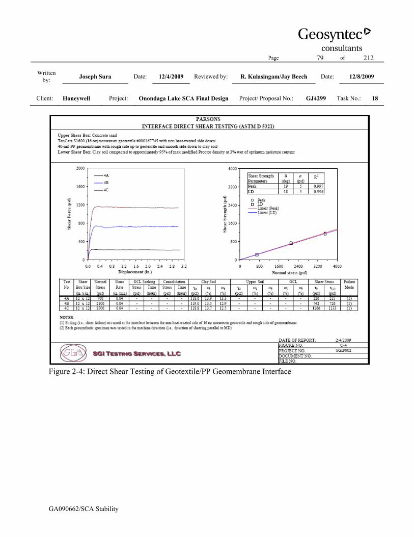
Page 79 of 212
Written by: Joseph Sura Date: 12/4/2009 Reviewed by: R. Kulasingam/Jay Beech Date: 12/8/2009
Client: Honeywell Project: Onondaga Lake SCA Final Design Project/ Proposal No.: GJ4299 Task No.: 18
GA090662/SCA Stability
Figure 2-4: Direct Shear Testing of Geotextile/PP Geomembrane Interface

Page 80 of 212
Written by: Joseph Sura Date: 12/4/2009 Reviewed by: R. Kulasingam/Jay Beech Date: 12/8/2009
Client: Honeywell Project: Onondaga Lake SCA Final Design Project/ Proposal No.: GJ4299 Task No.: 18
GA090662/SCA Stability
Figure 2-5: Direct Shear Testing of Geo-tube/Geo-tube Interface

Page 81 of 212
Written by: Joseph Sura Date: 12/4/2009 Reviewed by: R. Kulasingam/Jay Beech Date: 12/8/2009
Client: Honeywell Project: Onondaga Lake SCA Final Design Project/ Proposal No.: GJ4299 Task No.: 18
GA090662/SCA Stability
Attachment 3 Slope Stability Analyses Using the Maximum Laboratory Measured
Liner Friction Angles

Page 82 of 212
Written by: Joseph Sura Date: 12/4/2009 Reviewed by: R. Kulasingam/Jay Beech Date: 12/8/2009
Client: Honeywell Project: Onondaga Lake SCA Final Design Project/ Proposal No.: GJ4299 Task No.: 18
GA090662/SCA Stability
Slope stability analyses were performed for the critical cases of Cross-Section A-A using the
maximum friction angles found from laboratory testing of possible liner system materials. This is intended to show an expected range of calculated FS values based on the laboratory variability in effective stress friction angle. The maximum liner effective stress peak and residual friction angles found in laboratory testing are 27 degrees and 18 degrees, respectively.
It is noted that the horizontal geo-tube/geo-tube interface has been modeled with peak and residual effective stress friction angles of 15 degrees and 12 degrees, respectively, in the following analyses, and other material properties are modeled as discussed in the main text.
Table 3-1 on the following page shows the FS for the critical liner case of one column of the liner slipping under one column geo-tubes. This case was evaluated using Janbu’s method for peak and residual shear strengths before and after construction of the final cover. These cases can be compared with the equivalent Cross-Section A-A case from Table 2 for the minimum measured peak friction angle.

Page 83 of 212
Written by: Joseph Sura Date: 12/4/2009 Reviewed by: R. Kulasingam/Jay Beech Date: 12/8/2009
Client: Honeywell Project: Onondaga Lake SCA Final Design Project/ Proposal No.: GJ4299 Task No.: 18
GA090662/SCA Stability
Table 3-1: Critical Liner Case for Cross-Section A-A using the Maximum Laboratory Effective Stress Friction Angle
Case Calculated FS Target FS Peak Friction Angle, without Final Cover[1] 1.88 1.3
Residual Friction Angle, without Final Cover[2] 1.36 1.1 Peak Friction Angle, with Final Cover[1] 1.94 1.5
Residual Friction Angle, with Final Cover[2] 1.40 1.3 Notes: 1. These FS values are calculated using the laboratory values of peak effective stress friction
angle for the geo-tube/geo-tube horizontal interface (15 degrees) and maximum peak effective stress friction angle for the liner system (27 degrees). The laboratory test data are shown in Figures 2-2 and 2-5 of Attachment 2.
2. These FS values are calculated using the laboratory values of residual effective stress friction angle for the geo-tube/geo-tube horizontal interface (12 degrees) and maximum residual effective stress friction angle for the liner system (18 degrees). The laboratory test data are shown in Figures 2-4 and 2-5 of Attachment 2.
3. This table calculates the FS for the critical liner case of one column of geo-tubes.

Page 84 of 212
Written by: Joseph Sura Date: 12/4/2009 Reviewed by: R. Kulasingam/Jay Beech Date: 12/8/2009
Client: Honeywell Project: Onondaga Lake SCA Final Design Project/ Proposal No.: GJ4299 Task No.: 18
GA090662/SCA Stability
Attachment 4 Back-Calculation of Required Geo-tube\Geo-tube and Liner System
Interface Shear Strengths

Page 85 of 212
Written by: Joseph Sura Date: 12/4/2009 Reviewed by: R. Kulasingam/Jay Beech Date: 12/8/2009
Client: Honeywell Project: Onondaga Lake SCA Final Design Project/ Proposal No.: GJ4299 Task No.: 18
GA090662/SCA Stability
Notes: The stability analyses discussed in the Results and Discussion section of this package were
performed using friction angles from laboratory testing on materials that will likely be used for the geo-tubes and liner. Since the required FS values were met, the ability to achieve adequate stability using typical construction materials has been established. However, the use of different materials may be preferred; therefore, development of a range of acceptable parameters is required.
As described in the Analyzed Cases section, once the critical cases were identified for geo-tube and liner stability slip modes, peak and residual effective stress friction angles for the geo-tube interface and the proposed liner could be back-calculated. Since Cross-Section A-A was the more critical cross section of the two, the back-calculations were only performed on that cross section. These back-calculations indicated the following:
• For the interim condition before final cover placement, peak effective stress friction angles of 13 degrees for the horizontal geo-tube interface and 14.8 degrees for the proposed liner are required. In addition, residual effective stress friction angles of 11.0 degrees for the horizontal geo-tube interface and 12.4 degrees for the proposed liner are required.
• For the final condition after final cover placement, peak effective stress friction angles of 13.8 degrees for the horizontal geo-tube interface and 18.3 degrees for the proposed liner are required. In addition, residual effective stress friction angles of 11.6 degrees for the horizontal geo-tube interface and 16.1 degrees for the proposed liner are required.
• Therefore, the minimum required peak effective stress friction angles to meet the target FS values for both interim and final conditions are 13.8 degrees for the horizontal geo-tube interface and 18.3 degrees for the proposed liner system. The minimum required residual effective stress friction angles to meet the target FS values for both the interim and final conditions are 11.6 degrees for the horizontal geo-tube interface and 16.1 degrees for the proposed liner. Alternative combinations of horizontal geo-tube interface and liner interface strengths may be acceptable as shown in Figures 4-5 and 4-6.
These back-calculated friction angles for interim and final conditions are plotted in Figures 4-1 through 4-6. The blue boxes indicate the friction angles found from the laboratory testing of commercially available products, as shown in Attachment 2. The combinations of horizontal
Page 86 of 212
Written by: Joseph Sura Date: 12/4/2009 Reviewed by: R. Kulasingam/Jay Beech Date: 12/8/2009
Client: Honeywell Project: Onondaga Lake SCA Final Design Project/ Proposal No.: GJ4299 Task No.: 18
GA090662/SCA Stability
geo-tube and liner interface friction angles required to reach the target FS are shown in Tables 4-1 through 4-4.

Page 87 of 212
Written by: Joseph Sura Date: 12/4/2009 Reviewed by: R. Kulasingam/Jay Beech Date: 12/8/2009
Client: Honeywell Project: Onondaga Lake SCA Final Design Project/ Proposal No.: GJ4299 Task No.: 18
GA090662/SCA Stability
02468
10121416182022
10 11 12 13 14 15 16
Pea
k Li
ner F
rictio
n A
ngle
(deg
ree)
Peak Geo-tube Interface Friction Angle (degree)
FS >= 1.3
Geo‐tube and Liner Slip Mode
Geo‐tube Slip Mode
Range of Laboratory Values
Figure 4-1: Sensitivity Analysis of Liner Interface Friction Angle Without Final Cover, using
Peak Strengths

Page 88 of 212
Written by: Joseph Sura Date: 12/4/2009 Reviewed by: R. Kulasingam/Jay Beech Date: 12/8/2009
Client: Honeywell Project: Onondaga Lake SCA Final Design Project/ Proposal No.: GJ4299 Task No.: 18
GA090662/SCA Stability
02468
10121416182022
10 11 12 13 14 15 16
Res
idua
l Lin
er F
rictio
n A
ngle
(deg
ree)
Residual Geo-tube Interface Friction Angle (degree)
FS >= 1.1
Geo‐tube and Liner Slip Mode
Geo‐tube Slip ModeRange of Laboratory Values
Figure 4-2: Sensitivity Analysis of Liner Interface Friction Angle Without Final Cover, using
Residual Strengths

Page 89 of 212
Written by: Joseph Sura Date: 12/4/2009 Reviewed by: R. Kulasingam/Jay Beech Date: 12/8/2009
Client: Honeywell Project: Onondaga Lake SCA Final Design Project/ Proposal No.: GJ4299 Task No.: 18
GA090662/SCA Stability
02468
1012141618202224
12 13 14 15 16 17
Pea
k Li
ner F
rictio
n A
ngle
(deg
ree)
Peak Geo-tube Interface Friction Angle (degree)
FS >= 1.5
Geo‐tube and Liner Slip Mode
Geo‐tube Slip Mode
Range of Laboratory Values
Figure 4-3: Sensitivity Analysis of Liner Interface Friction Angle after Final Cover Placement,
using Peak Strengths

Page 90 of 212
Written by: Joseph Sura Date: 12/4/2009 Reviewed by: R. Kulasingam/Jay Beech Date: 12/8/2009
Client: Honeywell Project: Onondaga Lake SCA Final Design Project/ Proposal No.: GJ4299 Task No.: 18
GA090662/SCA Stability
02468
1012141618202224
10 11 12 13 14 15
Res
idua
l Lin
er F
rictio
n A
ngle
(deg
ree)
Residual Geo-tube Interface Friction Angle (degree)
FS >= 1.3
Geo‐tube and Liner Slip Mode
Geo‐tube Slip Mode
Range of Laboratory Values
Figure 4-4: Sensitivity Analysis of Liner Interface Friction Angle after Final Cover Placement,
using Residual Strengths

Page 91 of 212
Written by: Joseph Sura Date: 12/4/2009 Reviewed by: R. Kulasingam/Jay Beech Date: 12/8/2009
Client: Honeywell Project: Onondaga Lake SCA Final Design Project/ Proposal No.: GJ4299 Task No.: 18
GA090662/SCA Stability
02468
1012141618202224
12 13 14 15 16 17
Pea
k Li
ner F
rictio
n A
ngle
(deg
ree)
Peak Geo-tube Interface Friction Angle (degree)
MinimumRequiredValues
Geo‐tube and Liner Slip Mode
Geo‐tube Slip Mode
Range of Laboratory Values
Figure 4-5: Sensitivity Analysis of Peak Liner Friction Angle: Minimum Required Values
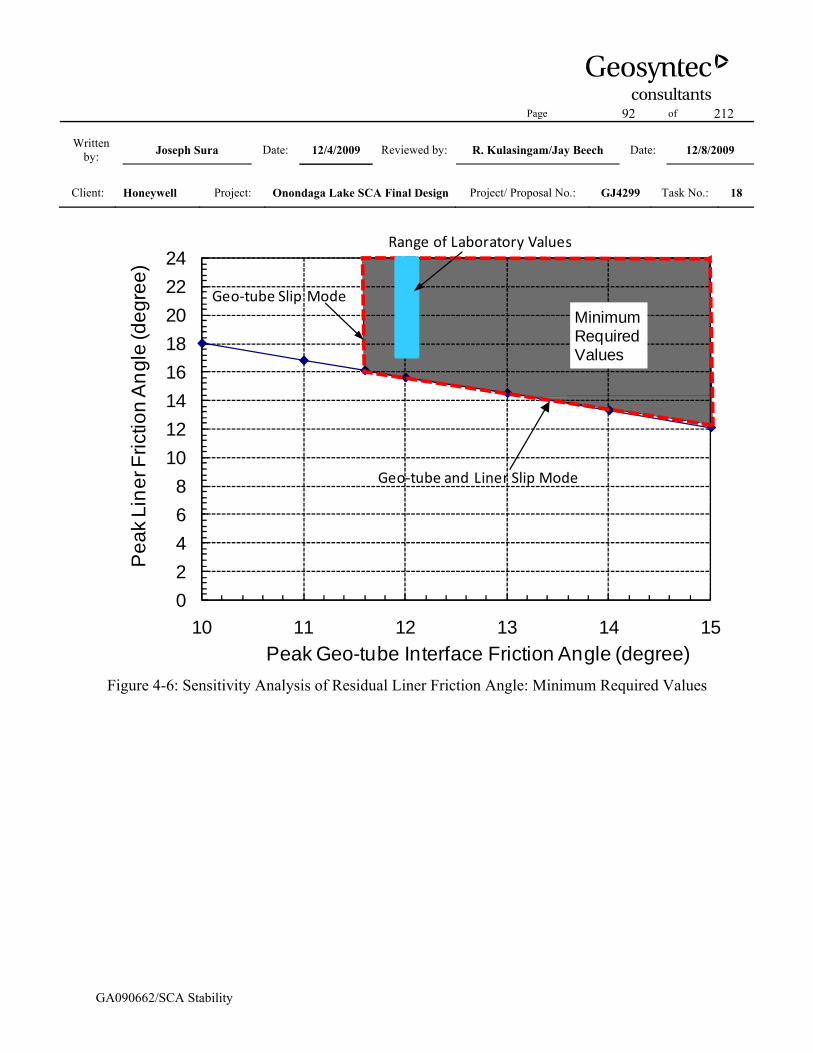
Page 92 of 212
Written by: Joseph Sura Date: 12/4/2009 Reviewed by: R. Kulasingam/Jay Beech Date: 12/8/2009
Client: Honeywell Project: Onondaga Lake SCA Final Design Project/ Proposal No.: GJ4299 Task No.: 18
GA090662/SCA Stability
02468
1012141618202224
10 11 12 13 14 15
Pea
k Li
ner F
rictio
n A
ngle
(deg
ree)
Peak Geo-tube Interface Friction Angle (degree)
MinimumRequired Values
Geo‐tube and Liner Slip Mode
Geo‐tube Slip Mode
Range of Laboratory Values
Figure 4-6: Sensitivity Analysis of Residual Liner Friction Angle: Minimum Required Values

Page 93 of 212
Written by: Joseph Sura Date: 12/4/2009 Reviewed by: R. Kulasingam/Jay Beech Date: 12/8/2009
Client: Honeywell Project: Onondaga Lake SCA Final Design Project/ Proposal No.: GJ4299 Task No.: 18
GA090662/SCA Stability
Table 4-1. Sensitivity Analysis of Liner Interface Friction Angle Without Final Cover, using
Peak Strengths
Geotube interface friction angle (degree)
Liner friction angle (degree)
10 19.311 17.812 16.313 14.814 13.315 11.716 10.1
Notes: 1. For peak shear strengths, this table presents the minimum required liner friction angles and corresponding
geo-tube/geo-tube interface friction angles to achieve the target FS of 1.3 for the liner slip mode. 2. These values were calculated using Cross-Section A-A without cover for the most critical liner slip case
involving one column of geo-tubes. 3. These values are plotted graphically in Figure 4-1. 4. For peak shear strengths, in order to achieve the target FS of 1.3 for the geo-tube slip mode, the minimum
required geo-tube/geo-tube horizontal interface friction angle was back-calculated to be 13.0 degrees, which corresponds to a minimum liner friction angle of 14.8 degrees.
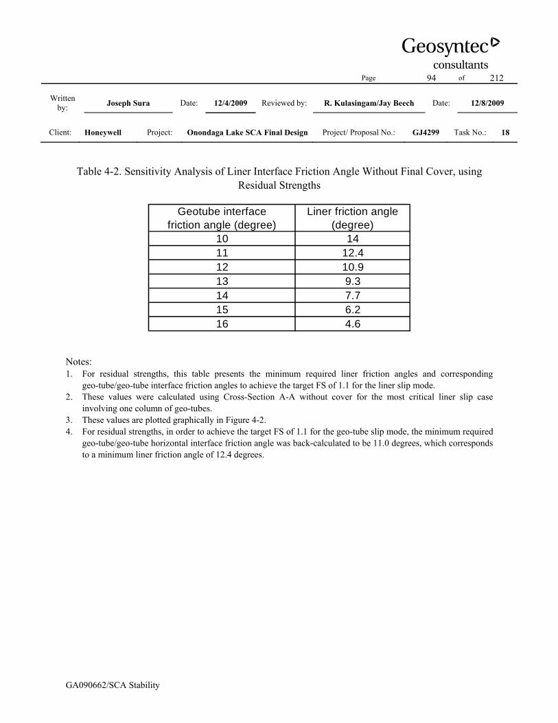
Page 94 of 212
Written by: Joseph Sura Date: 12/4/2009 Reviewed by: R. Kulasingam/Jay Beech Date: 12/8/2009
Client: Honeywell Project: Onondaga Lake SCA Final Design Project/ Proposal No.: GJ4299 Task No.: 18
GA090662/SCA Stability
Table 4-2. Sensitivity Analysis of Liner Interface Friction Angle Without Final Cover, using
Residual Strengths
Geotube interface friction angle (degree)
Liner friction angle (degree)
10 1411 12.412 10.913 9.314 7.715 6.216 4.6
Notes: 1. For residual strengths, this table presents the minimum required liner friction angles and corresponding
geo-tube/geo-tube interface friction angles to achieve the target FS of 1.1 for the liner slip mode. 2. These values were calculated using Cross-Section A-A without cover for the most critical liner slip case
involving one column of geo-tubes. 3. These values are plotted graphically in Figure 4-2. 4. For residual strengths, in order to achieve the target FS of 1.1 for the geo-tube slip mode, the minimum required
geo-tube/geo-tube horizontal interface friction angle was back-calculated to be 11.0 degrees, which corresponds to a minimum liner friction angle of 12.4 degrees.

Page 95 of 212
Written by: Joseph Sura Date: 12/4/2009 Reviewed by: R. Kulasingam/Jay Beech Date: 12/8/2009
Client: Honeywell Project: Onondaga Lake SCA Final Design Project/ Proposal No.: GJ4299 Task No.: 18
GA090662/SCA Stability
Table 4-3. Sensitivity Analysis of Liner Interface Friction Angle after Final Cover Placement,
using Peak Strengths
Geotube interface friction angle (degree)
Liner friction angle (degree)
12 20.313 19.2
13.8 18.314 18.115 16.916 15.717 14.5
Notes: 1. For peak shear strengths, this table presents the minimum required liner friction angles and corresponding
geo-tube/geo-tube interface friction angles to achieve the target FS of 1.5 for the liner slip mode. 2. These values were calculated using Cross-Section A-A without cover for the most critical liner slip case
involving one column of geo-tubes. 3. These values are plotted graphically in Figure 4-3. 4. For peak shear strengths, in order to achieve the target FS of 1.5 for the geo-tube slip mode, the minimum
required geo-tube/geo-tube horizontal interface friction angle was back-calculated to be 13.8 degrees, which corresponds to a minimum liner friction angle of 18.3 degrees.

Page 96 of 212
Written by: Joseph Sura Date: 12/4/2009 Reviewed by: R. Kulasingam/Jay Beech Date: 12/8/2009
Client: Honeywell Project: Onondaga Lake SCA Final Design Project/ Proposal No.: GJ4299 Task No.: 18
GA090662/SCA Stability
Table 4-4. Sensitivity Analysis of Liner Interface Friction Angle after Final Cover Placement,
using Residual Strengths
Geotube interface friction angle (degree)
Liner friction angle (degree)
10 1811 16.8
11.6 16.112 15.613 14.514 13.315 12.1
Notes: 1. For residual strengths, this table presents the minimum required liner friction angles and corresponding
geo-tube/geo-tube interface friction angles to achieve the target FS of 1.3 for the liner slip mode. 2. These values were calculated using Cross-Section A-A without cover for the most critical liner slip case
involving one column of geo-tubes. 3. These values are plotted graphically in Figure 4-4. 4. For residual strengths, in order to achieve the target FS of 1.3 for the geo-tube slip mode, the minimum required
geo-tube/geo-tube horizontal interface friction angle was back-calculated to be 11.6 degrees, which corresponds to a minimum liner friction angle of 16.1 degrees.

Page 97 of 212
Written by: Joseph Sura Date: 12/4/2009 Reviewed by: R. Kulasingam/Jay Beech Date: 12/8/2009
Client: Honeywell Project: Onondaga Lake SCA Final Design Project/ Proposal No.: GJ4299 Task No.: 18
GA090662/SCA Stability
Attachment 5 SLIDE Output Files

Page 98 of 212
Written by: Joseph Sura Date: 12/4/2009 Reviewed by: R. Kulasingam/Jay Beech Date: 12/8/2009
Client: Honeywell Project: Onondaga Lake SCA Final Design Project/ Proposal No.: GJ4299 Task No.: 18
GA090662/SCA Stability
Notes
1.) The error messages in the output files are a result of invalid slip surfaces generated by the SLIDE program during the automatic search for the most critical slip surface. The invalid slip surfaces included surfaces that are beyond the defined model boundaries, surfaces that are kinematically not feasible, and surfaces that mathematically do not converge to a solution. The invalid slip surfaces do not affect the valid slip surfaces from which the critical slip surface is identified. A list of error codes identifying the meaning of each message is included immediately after this notes page.
2.) In the SLIDE output files, the model boundaries and definitions are only included twice for each Cross-Section: once before placement of cover and once after the final cover placement, to avoid redundancy.

Page 99 of 212
Written by: Joseph Sura Date: 12/4/2009 Reviewed by: R. Kulasingam/Jay Beech Date: 12/8/2009
Client: Honeywell Project: Onondaga Lake SCA Final Design Project/ Proposal No.: GJ4299 Task No.: 18
GA090662/SCA Stability
List of Error Codes -101 = Only one (or zero) surface/slope interactions. -102 = Two surface / slope intersections, but resulting arc is actually outside soil region. -103 = Two surface / slope intersections, but one or more surface / nonslope external polygon intersections lie between them. This usually occurs when the slip surface extends past the bottom of the soil region, but may also occur on a benched slope model with two sets of Slope Limits. -105 = More than two surface / slope intersections with no valid slip surface. -106 = Average slice width is less than 0.0001 * (maximum horizontal extent of soil region). This limitation is imposed to avoid numerical errors which may result from too many slices, or too small a slip region. -107 = Total driving moment or total driving force is negative. This will occur if the wrong failure direction is specified, or if high external or anchor loads are applied against the failure direction. -108 = Total driving moment or total driving force < 0.1. This is to limit the calculation of extremely high safety factors if the driving force is very small (0.1 is an arbitrary number). -110 = The water table or a piezoline does not span the slip region for a given slip surface, when Water Surfaces is specified as the method of pore pressure calculation. If this error occurs, check that the water table or piezoline(s) span the appropriate soil cells. -111 = safety factor equation did not converge -112 = The coefficient M-Alpha = cos(alpha)(1+tan(alpha)tan(phi)/F)< 0.2 for the final iteration of the safety factor calculation. This screens out some slip surfaces which may not be valid in the context of the analysis, in particular, deep seated slip surfaces with many high negative base angle slices in the passive zone. -113 = Surface intersects outside slope limits. -116 = Not enough slices to analyze the surface. Increase the number of slices in the job control in the modeler. -1000 = No valid slip surfaces are generated at a grid center. Unable to draw a surface.
Page 100 of 212
Written by: Joseph Sura Date: 12/4/2009 Reviewed by: R. Kulasingam/Jay Beech Date: 12/8/2009
Client: Honeywell Project: Onondaga Lake SCA Final Design Project/ Proposal No.: GJ4299 Task No.: 18
GA090662/SCA Stability
Cross-Section A-A: Before Placement of Final Cover
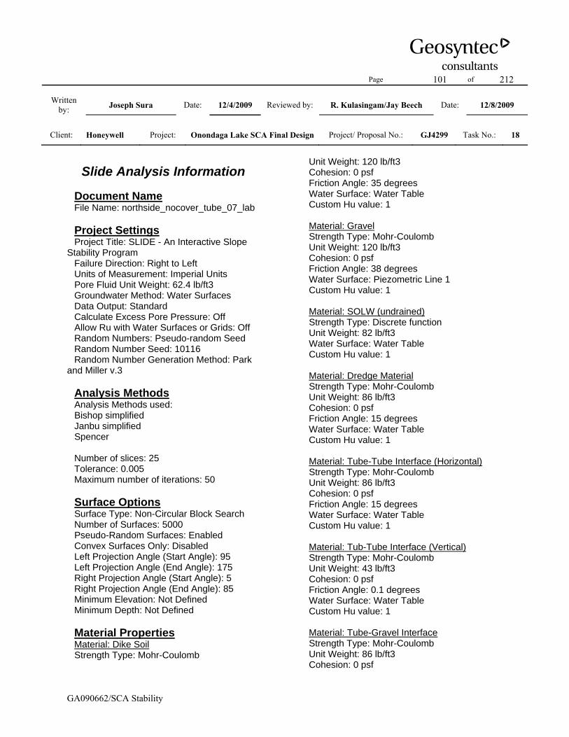
Page 101 of 212
Written by: Joseph Sura Date: 12/4/2009 Reviewed by: R. Kulasingam/Jay Beech Date: 12/8/2009
Client: Honeywell Project: Onondaga Lake SCA Final Design Project/ Proposal No.: GJ4299 Task No.: 18
GA090662/SCA Stability
Slide Analysis Information Document Name File Name: northside_nocover_tube_07_lab Project Settings Project Title: SLIDE - An Interactive Slope Stability Program Failure Direction: Right to Left Units of Measurement: Imperial Units Pore Fluid Unit Weight: 62.4 lb/ft3 Groundwater Method: Water Surfaces Data Output: Standard Calculate Excess Pore Pressure: Off Allow Ru with Water Surfaces or Grids: Off Random Numbers: Pseudo-random Seed Random Number Seed: 10116 Random Number Generation Method: Park and Miller v.3 Analysis Methods Analysis Methods used: Bishop simplified Janbu simplified Spencer Number of slices: 25 Tolerance: 0.005 Maximum number of iterations: 50 Surface Options Surface Type: Non-Circular Block Search Number of Surfaces: 5000 Pseudo-Random Surfaces: Enabled Convex Surfaces Only: Disabled Left Projection Angle (Start Angle): 95 Left Projection Angle (End Angle): 175 Right Projection Angle (Start Angle): 5 Right Projection Angle (End Angle): 85 Minimum Elevation: Not Defined Minimum Depth: Not Defined Material Properties Material: Dike Soil Strength Type: Mohr-Coulomb
Unit Weight: 120 lb/ft3 Cohesion: 0 psf Friction Angle: 35 degrees Water Surface: Water Table Custom Hu value: 1 Material: Gravel Strength Type: Mohr-Coulomb Unit Weight: 120 lb/ft3 Cohesion: 0 psf Friction Angle: 38 degrees Water Surface: Piezometric Line 1 Custom Hu value: 1 Material: SOLW (undrained) Strength Type: Discrete function Unit Weight: 82 lb/ft3 Water Surface: Water Table Custom Hu value: 1 Material: Dredge Material Strength Type: Mohr-Coulomb Unit Weight: 86 lb/ft3 Cohesion: 0 psf Friction Angle: 15 degrees Water Surface: Water Table Custom Hu value: 1 Material: Tube-Tube Interface (Horizontal) Strength Type: Mohr-Coulomb Unit Weight: 86 lb/ft3 Cohesion: 0 psf Friction Angle: 15 degrees Water Surface: Water Table Custom Hu value: 1 Material: Tub-Tube Interface (Vertical) Strength Type: Mohr-Coulomb Unit Weight: 43 lb/ft3 Cohesion: 0 psf Friction Angle: 0.1 degrees Water Surface: Water Table Custom Hu value: 1 Material: Tube-Gravel Interface Strength Type: Mohr-Coulomb Unit Weight: 86 lb/ft3 Cohesion: 0 psf
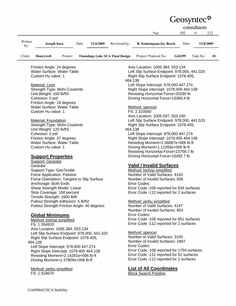
Page 102 of 212
Written by: Joseph Sura Date: 12/4/2009 Reviewed by: R. Kulasingam/Jay Beech Date: 12/8/2009
Client: Honeywell Project: Onondaga Lake SCA Final Design Project/ Proposal No.: GJ4299 Task No.: 18
GA090662/SCA Stability
Friction Angle: 24 degrees Water Surface: Water Table Custom Hu value: 1 Material: Liner Strength Type: Mohr-Coulomb Unit Weight: 100 lb/ft3 Cohesion: 0 psf Friction Angle: 19 degrees Water Surface: Water Table Custom Hu value: 1 Material: Foundation Strength Type: Mohr-Coulomb Unit Weight: 120 lb/ft3 Cohesion: 0 psf Friction Angle: 37 degrees Water Surface: Water Table Custom Hu value: 1 Support Properties Support: Geotube Geotube Support Type: GeoTextile Force Application: Passive Force Orientation: Tangent to Slip Surface Anchorage: Both Ends Shear Strength Model: Linear Strip Coverage: 100 percent Tensile Strength: 1600 lb/ft Pullout Strength Adhesion: 5 lb/ft2 Pullout Strength Friction Angle: 40 degrees Global Minimums Method: bishop simplified FS: 1.554920 Axis Location: 1005.384, 553.134 Left Slip Surface Endpoint: 978.000, 441.320 Right Slip Surface Endpoint: 1078.405, 464.138 Left Slope Intercept: 978.000 447.274 Right Slope Intercept: 1078.405 464.138 Resisting Moment=2.14281e+006 lb-ft Driving Moment=1.37809e+006 lb-ft Method: janbu simplified FS: 1.518670
Axis Location: 1005.384, 553.134 Left Slip Surface Endpoint: 978.000, 441.320 Right Slip Surface Endpoint: 1078.405, 464.138 Left Slope Intercept: 978.000 447.274 Right Slope Intercept: 1078.405 464.138 Resisting Horizontal Force=20290 lb Driving Horizontal Force=13360.4 lb Method: spencer FS: 2.310560 Axis Location: 1005.597, 553.240 Left Slip Surface Endpoint: 978.000, 441.533 Right Slip Surface Endpoint: 1078.405, 464.138 Left Slope Intercept: 978.000 447.274 Right Slope Intercept: 1078.405 464.138 Resisting Moment=2.56687e+006 lb-ft Driving Moment=1.11093e+006 lb-ft Resisting Horizontal Force=23758.7 lb Driving Horizontal Force=10282.7 lb Valid / Invalid Surfaces Method: bishop simplified Number of Valid Surfaces: 4164 Number of Invalid Surfaces: 836 Error Codes: Error Code -108 reported for 834 surfaces Error Code -112 reported for 2 surfaces Method: janbu simplified Number of Valid Surfaces: 4147 Number of Invalid Surfaces: 853 Error Codes: Error Code -108 reported for 851 surfaces Error Code -112 reported for 2 surfaces Method: spencer Number of Valid Surfaces: 3193 Number of Invalid Surfaces: 1807 Error Codes: Error Code -108 reported for 1754 surfaces Error Code -111 reported for 51 surfaces Error Code -112 reported for 2 surfaces List of All Coordinates Block Search Polyline

Page 103 of 212
Written by: Joseph Sura Date: 12/4/2009 Reviewed by: R. Kulasingam/Jay Beech Date: 12/8/2009
Client: Honeywell Project: Onondaga Lake SCA Final Design Project/ Proposal No.: GJ4299 Task No.: 18
GA090662/SCA Stability
978.000 441.318 1017.040 441.054 Material Boundary 953.000 433.500 958.000 433.500 1400.000 427.700 Material Boundary 978.000 441.524 997.000 441.309 998.500 441.292 1017.009 441.083 1018.508 441.066 1037.000 440.856 1038.500 440.839 1057.015 440.630 1058.509 440.613 1096.999 440.178 1098.506 440.161 1117.012 439.951 1118.512 439.934 1137.006 439.725 1138.505 439.708 1157.006 439.499 1158.500 439.482 1176.999 439.273 1178.492 439.256 1197.013 439.046 1198.512 439.029 1217.005 438.820 1218.499 438.803 1237.000 438.594 1238.506 438.577 1257.010 438.368 1258.509 438.351 1277.013 438.141 1278.513 438.124 1296.975 437.915 1298.469 437.899 1317.013 437.689 1318.507 437.672 1336.969 437.463 1338.469 437.446 1357.000 437.236 1358.510 437.219 1376.969 437.011 1378.475 436.993
1400.000 436.750 Material Boundary 998.000 447.048 1017.014 446.832 1018.514 446.815 1037.015 446.606 1038.521 446.589 1057.021 446.380 1058.520 446.363 1077.016 446.154 1078.515 446.137 1097.005 445.928 1098.523 445.910 1117.022 445.701 1118.509 445.684 1137.023 445.475 1138.511 445.458 1157.009 445.249 1158.509 445.232 1177.011 445.023 1178.494 445.006 1197.022 444.796 1198.509 444.779 1217.011 444.570 1218.511 444.553 1237.016 444.344 1238.509 444.327 1257.015 444.117 1258.515 444.101 1277.009 443.891 1278.515 443.874 1296.975 443.665 1298.475 443.648 1317.016 443.439 1318.515 443.422 1336.981 443.213 1338.481 443.196 1357.016 442.986 1358.516 442.969 1376.981 442.760 1378.481 442.743 1400.000 442.500 Material Boundary 998.000 447.298 1017.014 447.082 1018.514 447.066

Page 104 of 212
Written by: Joseph Sura Date: 12/4/2009 Reviewed by: R. Kulasingam/Jay Beech Date: 12/8/2009
Client: Honeywell Project: Onondaga Lake SCA Final Design Project/ Proposal No.: GJ4299 Task No.: 18
GA090662/SCA Stability
1037.016 446.856 1038.521 446.839 1057.021 446.630 1058.521 446.613 1077.016 446.404 1078.516 446.387 1097.005 446.178 1098.524 446.160 1117.022 445.951 1118.510 445.934 1137.024 445.725 1138.511 445.708 1157.010 445.499 1158.510 445.482 1177.011 445.273 1178.494 445.256 1197.022 445.046 1198.510 445.029 1217.011 444.820 1218.511 444.803 1237.016 444.594 1238.509 444.577 1257.016 444.368 1258.515 444.351 1277.010 444.141 1278.516 444.124 1296.975 443.915 1298.475 443.898 1317.016 443.689 1318.516 443.672 1336.981 443.463 1338.481 443.446 1357.016 443.236 1358.516 443.219 1376.981 443.010 1378.481 442.993 1400.000 442.750 Material Boundary 1018.000 452.821 1037.021 452.606 1038.521 452.589 1057.007 452.380 1058.501 452.363 1077.021 452.154 1078.527 452.137 1096.995 451.928 1098.501 451.911
1117.028 451.701 1118.527 451.684 1137.001 451.475 1138.501 451.458 1157.027 451.249 1158.521 451.232 1176.995 451.023 1178.495 451.006 1197.028 450.796 1198.521 450.779 1217.001 450.570 1218.501 450.553 1237.022 450.344 1238.515 450.327 1257.007 450.118 1258.501 450.101 1277.021 449.891 1278.521 449.874 1297.001 449.665 1298.501 449.648 1317.028 449.439 1318.521 449.422 1337.008 449.213 1338.501 449.196 1357.022 448.986 1358.521 448.969 1377.008 448.760 1378.508 448.743 1400.000 448.500 Material Boundary 1018.000 453.071 1037.022 452.856 1038.521 452.839 1057.007 452.630 1058.501 452.613 1077.022 452.404 1078.528 452.387 1096.996 452.178 1098.501 452.161 1117.028 451.951 1118.528 451.934 1137.002 451.725 1138.501 451.708 1157.028 451.499 1158.522 451.482 1176.996 451.273 1178.496 451.256

Page 105 of 212
Written by: Joseph Sura Date: 12/4/2009 Reviewed by: R. Kulasingam/Jay Beech Date: 12/8/2009
Client: Honeywell Project: Onondaga Lake SCA Final Design Project/ Proposal No.: GJ4299 Task No.: 18
GA090662/SCA Stability
1197.028 451.046 1198.522 451.029 1217.001 450.820 1218.501 450.803 1237.022 450.594 1238.515 450.577 1257.007 450.368 1258.501 450.351 1277.022 450.141 1278.522 450.124 1297.002 449.915 1298.502 449.898 1317.028 449.689 1318.522 449.672 1337.008 449.463 1338.502 449.446 1357.022 449.236 1358.522 449.219 1377.008 449.010 1378.508 448.993 1400.000 448.750 Material Boundary 1038.000 458.595 1057.013 458.380 1058.512 458.363 1077.005 458.154 1078.505 458.137 1097.013 457.928 1098.513 457.911 1117.011 457.701 1118.498 457.685 1137.019 457.475 1138.507 457.458 1157.005 457.249 1158.498 457.232 1177.013 457.023 1178.518 457.006 1197.005 456.796 1198.498 456.779 1217.007 456.570 1218.501 456.553 1237.005 456.344 1238.511 456.327 1257.007 456.118 1258.507 456.101 1277.005 455.891 1278.505 455.874
1297.013 455.665 1298.513 455.648 1317.005 455.439 1318.505 455.422 1337.014 455.213 1338.507 455.196 1357.006 454.986 1358.511 454.969 1377.021 454.760 1378.513 454.743 1400.000 454.500 Material Boundary 1038.000 458.845 1057.013 458.630 1058.513 458.613 1077.006 458.404 1078.505 458.387 1097.013 458.178 1098.513 458.161 1117.011 457.951 1118.499 457.934 1137.020 457.725 1138.507 457.708 1157.005 457.499 1158.499 457.482 1177.013 457.273 1178.519 457.255 1197.006 457.046 1198.499 457.029 1217.007 456.820 1218.501 456.803 1237.006 456.594 1238.511 456.577 1257.007 456.368 1258.507 456.351 1277.005 456.141 1278.505 456.124 1297.014 455.915 1298.514 455.898 1317.005 455.689 1318.505 455.672 1337.014 455.463 1338.507 455.446 1357.006 455.236 1358.511 455.219 1377.021 455.010 1378.514 454.993

Page 106 of 212
Written by: Joseph Sura Date: 12/4/2009 Reviewed by: R. Kulasingam/Jay Beech Date: 12/8/2009
Client: Honeywell Project: Onondaga Lake SCA Final Design Project/ Proposal No.: GJ4299 Task No.: 18
GA090662/SCA Stability
1400.000 454.750 Material Boundary 958.000 435.500 997.000 435.059 998.500 435.042 1037.000 434.606 1038.494 434.589 1077.000 434.154 1078.500 434.137 1117.000 433.701 1118.494 433.684 1156.994 433.249 1158.494 433.232 1197.006 432.796 1198.500 432.779 1236.994 432.344 1238.494 432.327 1277.007 431.891 1278.507 431.874 1317.007 431.439 1318.507 431.422 1357.000 430.986 1358.499 430.969 1400.000 430.500 Material Boundary 978.000 441.274 997.000 441.059 998.500 441.042 1017.008 440.832 1018.508 440.816 1037.000 440.606 1038.500 440.589 1057.015 440.380 1058.508 440.363 1077.006 440.154 1078.494 440.137 1096.999 439.928 1098.505 439.911 1117.012 439.701 1118.511 439.684 1137.005 439.475 1138.505 439.458 1157.006 439.249 1158.500 439.232 1176.999 439.023 1178.492 439.006
1197.012 438.796 1198.512 438.779 1217.005 438.570 1218.499 438.553 1237.000 438.344 1238.506 438.327 1257.009 438.118 1258.509 438.101 1277.013 437.891 1278.512 437.874 1296.975 437.665 1298.469 437.649 1317.013 437.439 1318.507 437.422 1336.969 437.213 1338.469 437.196 1357.000 436.986 1358.510 436.969 1376.969 436.761 1378.475 436.743 1400.000 436.500 Material Boundary 958.000 435.750 997.000 435.309 998.500 435.292 1037.000 434.856 1038.494 434.839 1077.000 434.404 1078.500 434.387 1117.001 433.951 1118.494 433.934 1156.994 433.499 1158.494 433.482 1197.007 433.046 1198.500 433.029 1236.994 432.594 1238.494 432.577 1277.007 432.141 1278.507 432.124 1317.007 431.689 1318.507 431.672 1357.000 431.236 1358.500 431.219 1400.000 430.750 Material Boundary 895.681 432.081

Page 107 of 212
Written by: Joseph Sura Date: 12/4/2009 Reviewed by: R. Kulasingam/Jay Beech Date: 12/8/2009
Client: Honeywell Project: Onondaga Lake SCA Final Design Project/ Proposal No.: GJ4299 Task No.: 18
GA090662/SCA Stability
953.504 431.272 1400.000 425.200 Material Boundary 661.000 436.500 748.000 412.600 789.000 386.700 835.000 386.800 980.000 376.600 1400.000 367.800 Material Boundary 942.667 435.500 947.793 433.500 953.504 431.272 Material Boundary 1357.000 430.986 1357.000 431.236 1357.000 436.986 1357.000 437.236 Material Boundary 1358.499 430.969 1358.500 431.219 1358.510 436.969 1358.510 437.219 Material Boundary 1277.007 431.891 1277.007 432.141 1277.013 437.891 1277.013 438.141 Material Boundary 1278.507 431.874 1278.507 432.124 1278.512 437.874 1278.513 438.124 Material Boundary 1317.007 431.439 1317.007 431.689 1317.013 437.439 1317.013 437.689 Material Boundary 1318.507 431.422
1318.507 431.672 1318.507 437.422 1318.507 437.672 Material Boundary 1077.000 434.154 1077.000 434.404 1077.006 440.154 Material Boundary 1078.494 440.137 1078.500 434.387 1078.500 434.137 Material Boundary 1117.000 433.701 1117.001 433.951 1117.012 439.701 1117.012 439.951 Material Boundary 1118.494 433.684 1118.494 433.934 1118.511 439.684 1118.512 439.934 Material Boundary 1156.994 433.249 1156.994 433.499 1157.006 439.249 1157.006 439.499 Material Boundary 1158.494 433.232 1158.494 433.482 1158.500 439.232 1158.500 439.482 Material Boundary 1197.006 432.796 1197.007 433.046 1197.012 438.796 1197.013 439.046 Material Boundary 1198.500 432.779 1198.500 433.029 1198.512 438.779

Page 108 of 212
Written by: Joseph Sura Date: 12/4/2009 Reviewed by: R. Kulasingam/Jay Beech Date: 12/8/2009
Client: Honeywell Project: Onondaga Lake SCA Final Design Project/ Proposal No.: GJ4299 Task No.: 18
GA090662/SCA Stability
1198.512 439.029 Material Boundary 1236.994 432.344 1236.994 432.594 1237.000 438.344 1237.000 438.594 Material Boundary 1238.494 432.327 1238.494 432.577 1238.506 438.327 1238.506 438.577 Material Boundary 997.000 435.059 997.000 435.309 997.000 441.059 997.000 441.309 Material Boundary 998.500 435.042 998.500 435.292 998.500 441.042 998.500 441.292 Material Boundary 1037.000 434.606 1037.000 434.856 1037.000 440.606 1037.000 440.856 Material Boundary 1038.494 434.589 1038.494 434.839 1038.500 440.589 1038.500 440.839 Material Boundary 1296.975 437.665 1296.975 437.915 1296.975 443.665 1296.975 443.915 Material Boundary 1298.469 437.649 1298.469 437.899 1298.475 443.648
1298.475 443.898 Material Boundary 1336.969 437.213 1336.969 437.463 1336.981 443.213 1336.981 443.463 Material Boundary 1338.469 437.196 1338.469 437.446 1338.481 443.196 1338.481 443.446 Material Boundary 1376.969 436.761 1376.969 437.011 1376.981 442.760 1376.981 443.010 Material Boundary 1378.475 436.743 1378.475 436.993 1378.481 442.743 1378.481 442.993 Material Boundary 1257.009 438.118 1257.010 438.368 1257.015 444.117 1257.016 444.368 Material Boundary 1258.509 438.101 1258.509 438.351 1258.515 444.101 1258.515 444.351 Material Boundary 1096.999 439.928 1096.999 440.178 1097.005 445.928 1097.005 446.178 Material Boundary 1098.505 439.911 1098.506 440.161 1098.523 445.910

Page 109 of 212
Written by: Joseph Sura Date: 12/4/2009 Reviewed by: R. Kulasingam/Jay Beech Date: 12/8/2009
Client: Honeywell Project: Onondaga Lake SCA Final Design Project/ Proposal No.: GJ4299 Task No.: 18
GA090662/SCA Stability
1098.524 446.160 Material Boundary 1137.005 439.475 1137.006 439.725 1137.023 445.475 1137.024 445.725 Material Boundary 1138.505 439.458 1138.505 439.708 1138.511 445.458 1138.511 445.708 Material Boundary 1176.999 439.023 1176.999 439.273 1177.011 445.023 1177.011 445.273 Material Boundary 1178.492 439.006 1178.492 439.256 1178.494 445.006 1178.494 445.256 Material Boundary 1217.005 438.570 1217.005 438.820 1217.011 444.570 1217.011 444.820 Material Boundary 1218.499 438.553 1218.499 438.803 1218.511 444.553 1218.511 444.803 Material Boundary 1017.008 440.832 1017.009 441.083 1017.014 446.832 1017.014 447.082 Material Boundary 1018.508 440.816 1018.508 441.066 1018.514 446.815
1018.514 447.066 Material Boundary 1057.015 440.380 1057.015 440.630 1057.021 446.380 1057.021 446.630 Material Boundary 1058.508 440.363 1058.509 440.613 1058.520 446.363 1058.521 446.613 Material Boundary 1037.015 446.606 1037.016 446.856 1037.021 452.606 1037.022 452.856 Material Boundary 1038.521 446.589 1038.521 446.839 1038.521 452.589 1038.521 452.839 Material Boundary 1077.016 446.154 1077.016 446.404 1077.021 452.154 1077.022 452.404 Material Boundary 1078.515 446.137 1078.516 446.387 1078.527 452.137 1078.528 452.387 Material Boundary 1117.022 445.701 1117.022 445.951 1117.028 451.701 1117.028 451.951 Material Boundary 1118.509 445.684 1118.510 445.934 1118.527 451.684

Page 110 of 212
Written by: Joseph Sura Date: 12/4/2009 Reviewed by: R. Kulasingam/Jay Beech Date: 12/8/2009
Client: Honeywell Project: Onondaga Lake SCA Final Design Project/ Proposal No.: GJ4299 Task No.: 18
GA090662/SCA Stability
1118.528 451.934 Material Boundary 1157.009 445.249 1157.010 445.499 1157.027 451.249 1157.028 451.499 Material Boundary 1158.509 445.232 1158.510 445.482 1158.521 451.232 1158.522 451.482 Material Boundary 1197.022 444.796 1197.022 445.046 1197.028 450.796 1197.028 451.046 Material Boundary 1198.509 444.779 1198.510 445.029 1198.521 450.779 1198.522 451.029 Material Boundary 1237.016 444.344 1237.016 444.594 1237.022 450.344 1237.022 450.594 Material Boundary 1238.509 444.327 1238.509 444.577 1238.515 450.327 1238.515 450.577 Material Boundary 1277.009 443.891 1277.010 444.141 1277.021 449.891 1277.022 450.141 Material Boundary 1278.515 443.874 1278.516 444.124 1278.521 449.874
1278.522 450.124 Material Boundary 1317.016 443.439 1317.016 443.689 1317.028 449.439 1317.028 449.689 Material Boundary 1318.515 443.422 1318.516 443.672 1318.521 449.422 1318.522 449.672 Material Boundary 1357.016 442.986 1357.016 443.236 1357.022 448.986 1357.022 449.236 Material Boundary 1358.516 442.969 1358.516 443.219 1358.521 448.969 1358.522 449.219 Material Boundary 1057.007 452.380 1057.007 452.630 1057.013 458.380 1057.013 458.630 Material Boundary 1058.501 452.363 1058.501 452.613 1058.512 458.363 1058.513 458.613 Material Boundary 1098.501 451.911 1098.501 452.161 1098.513 457.911 1098.513 458.161 Material Boundary 1096.995 451.928 1096.996 452.178 1097.013 457.928

Page 111 of 212
Written by: Joseph Sura Date: 12/4/2009 Reviewed by: R. Kulasingam/Jay Beech Date: 12/8/2009
Client: Honeywell Project: Onondaga Lake SCA Final Design Project/ Proposal No.: GJ4299 Task No.: 18
GA090662/SCA Stability
1097.013 458.178 Material Boundary 1137.001 451.475 1137.002 451.725 1137.019 457.475 1137.020 457.725 Material Boundary 1138.501 451.458 1138.501 451.708 1138.507 457.458 1138.507 457.708 Material Boundary 1176.995 451.023 1176.996 451.273 1177.013 457.023 1177.013 457.273 Material Boundary 1178.495 451.006 1178.496 451.256 1178.518 457.006 1178.519 457.255 Material Boundary 1217.001 450.570 1217.001 450.820 1217.007 456.570 1217.007 456.820 Material Boundary 1218.501 450.553 1218.501 450.803 1218.501 456.553 1218.501 456.803 Material Boundary 1257.007 450.118 1257.007 450.368 1257.007 456.118 1257.007 456.368 Material Boundary 1258.501 450.101 1258.501 450.351 1258.507 456.101
1258.507 456.351 Material Boundary 1297.001 449.665 1297.002 449.915 1297.013 455.665 1297.014 455.915 Material Boundary 1298.501 449.648 1298.502 449.898 1298.513 455.648 1298.514 455.898 Material Boundary 1337.008 449.213 1337.008 449.463 1337.014 455.213 1337.014 455.463 Material Boundary 1338.501 449.196 1338.502 449.446 1338.507 455.196 1338.507 455.446 Material Boundary 1377.008 448.760 1377.008 449.010 1377.021 454.760 1377.021 455.010 Material Boundary 1378.508 448.743 1378.508 448.993 1378.513 454.743 1378.514 454.993 Material Boundary 1077.005 458.154 1077.006 458.404 1077.017 464.154 Material Boundary 1078.505 458.137 1078.505 458.387 1078.517 464.137

Page 112 of 212
Written by: Joseph Sura Date: 12/4/2009 Reviewed by: R. Kulasingam/Jay Beech Date: 12/8/2009
Client: Honeywell Project: Onondaga Lake SCA Final Design Project/ Proposal No.: GJ4299 Task No.: 18
GA090662/SCA Stability
Material Boundary 1117.011 457.701 1117.011 457.951 1117.011 463.701 Material Boundary 1118.498 457.685 1118.499 457.934 1118.511 463.684 Material Boundary 1157.005 457.249 1157.005 457.499 1157.011 463.249 Material Boundary 1158.498 457.232 1158.499 457.482 1158.511 463.232 Material Boundary 1197.005 456.796 1197.006 457.046 1197.017 462.796 Material Boundary 1198.498 456.779 1198.499 457.029 1198.517 462.779 Material Boundary 1237.005 456.344 1237.006 456.594 1237.024 462.344 Material Boundary 1238.511 456.327 1238.511 456.577 1238.517 462.327 Material Boundary 1277.005 455.891 1277.005 456.141 1277.011 461.891 Material Boundary 1278.505 455.874 1278.505 456.124
1278.505 461.874 Material Boundary 1317.005 455.439 1317.005 455.689 1317.011 461.439 Material Boundary 1318.505 455.422 1318.505 455.672 1318.517 461.422 Material Boundary 1357.006 454.986 1357.006 455.236 1357.017 460.986 Material Boundary 1358.511 454.969 1358.511 455.219 1358.511 460.969 Material Boundary 937.818 437.500 940.000 436.600 942.667 435.500 External Boundary 909.818 437.500 899.186 433.425 895.681 432.081 661.000 436.500 638.000 432.900 555.000 396.200 483.000 398.300 461.000 390.500 307.000 386.700 277.000 373.000 1.726 374.590 1.726 167.800 1400.000 167.800 1400.000 367.800 1400.000 425.200 1400.000 427.700 1400.000 430.500 1400.000 430.750 1400.000 436.500 1400.000 436.750

Page 113 of 212
Written by: Joseph Sura Date: 12/4/2009 Reviewed by: R. Kulasingam/Jay Beech Date: 12/8/2009
Client: Honeywell Project: Onondaga Lake SCA Final Design Project/ Proposal No.: GJ4299 Task No.: 18
GA090662/SCA Stability
1400.000 442.500 1400.000 442.750 1400.000 448.500 1400.000 448.750 1400.000 454.500 1400.000 454.750 1400.000 460.500 1358.511 460.969 1357.017 460.986 1318.517 461.422 1317.011 461.439 1278.505 461.874 1277.011 461.891 1238.517 462.327 1237.024 462.344 1198.517 462.779 1197.017 462.796 1158.511 463.232 1157.011 463.249 1118.511 463.684 1117.011 463.701 1078.517 464.137 1077.017 464.154 1038.000 464.595 1038.000 458.845 1038.000 458.595 1018.000 458.821 1018.000 453.071 1018.000 452.821 998.000 453.048 998.000 447.298 998.000 447.048 978.000 447.274 978.000 441.524 978.000 441.274 958.000 441.500 958.000 435.750 958.000 435.500 953.000 433.500 948.793 433.500 943.667 435.500 941.000 436.600 938.818 437.500 937.818 437.500 Piezo Line 946.230 434.500 948.793 434.500
958.000 434.500 1400.000 428.700 Water Table 715.262 421.594 900.000 417.000 935.504 416.272 1400.000 410.200 Focus/Block Search Point 1017.040 441.054 Focus/Block Search Point 1018.472 446.848 Focus/Block Search Point 1037.037 446.830 Focus/Block Search Point 1038.507 452.594 Focus/Block Search Point 1057.020 452.618 Focus/Block Search Point 1058.459 458.411 Focus/Block Search Point 1077.037 458.372 Focus/Block Search Point 1078.405 464.138 Support 1358.511 460.969 1400.000 460.500 Support 1400.000 454.750 1400.000 460.500 Support 1400.000 454.750 1358.511 455.219 Support 1358.511 455.219 1358.511 460.969
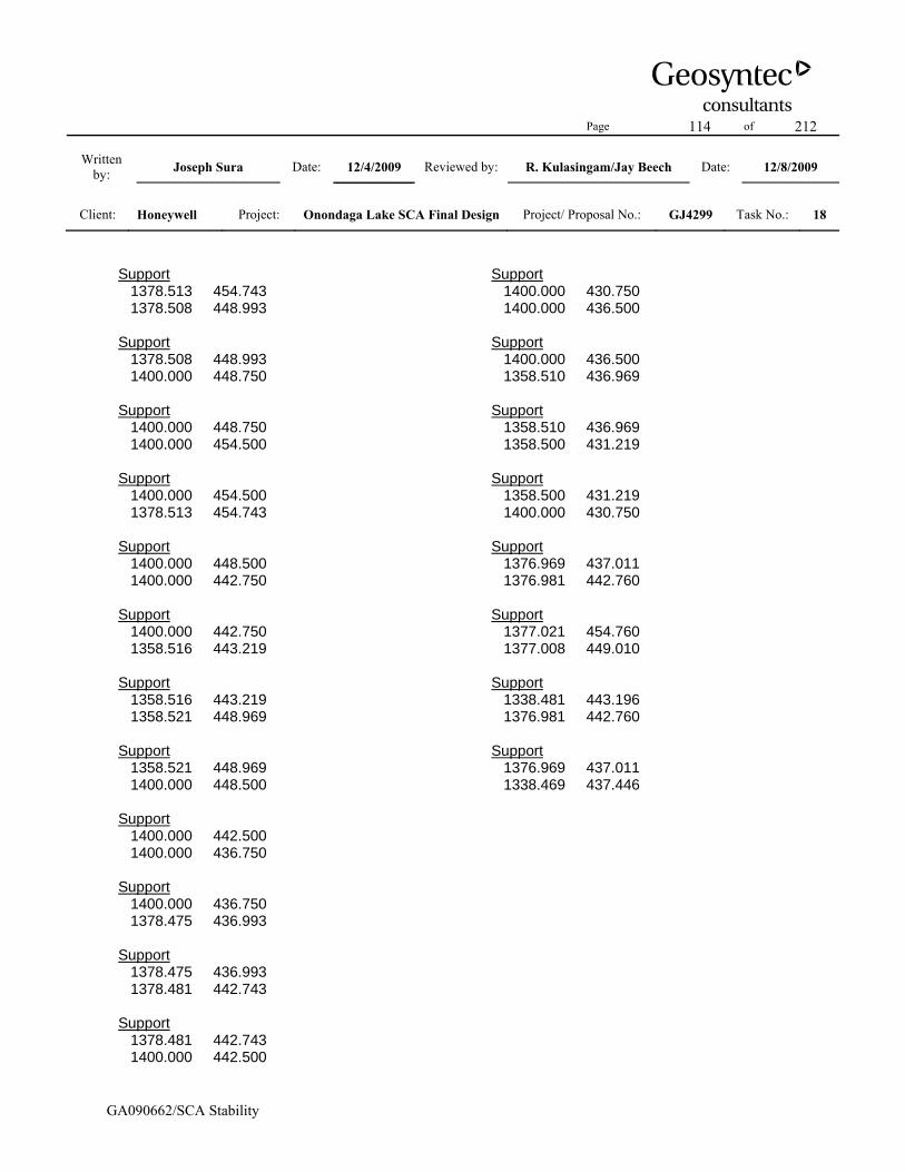
Page 114 of 212
Written by: Joseph Sura Date: 12/4/2009 Reviewed by: R. Kulasingam/Jay Beech Date: 12/8/2009
Client: Honeywell Project: Onondaga Lake SCA Final Design Project/ Proposal No.: GJ4299 Task No.: 18
GA090662/SCA Stability
Support 1378.513 454.743 1378.508 448.993 Support 1378.508 448.993 1400.000 448.750 Support 1400.000 448.750 1400.000 454.500 Support 1400.000 454.500 1378.513 454.743 Support 1400.000 448.500 1400.000 442.750 Support 1400.000 442.750 1358.516 443.219 Support 1358.516 443.219 1358.521 448.969 Support 1358.521 448.969 1400.000 448.500 Support 1400.000 442.500 1400.000 436.750 Support 1400.000 436.750 1378.475 436.993 Support 1378.475 436.993 1378.481 442.743 Support 1378.481 442.743 1400.000 442.500
Support 1400.000 430.750 1400.000 436.500 Support 1400.000 436.500 1358.510 436.969 Support 1358.510 436.969 1358.500 431.219 Support 1358.500 431.219 1400.000 430.750 Support 1376.969 437.011 1376.981 442.760 Support 1377.021 454.760 1377.008 449.010 Support 1338.481 443.196 1376.981 442.760 Support 1376.969 437.011 1338.469 437.446

Page 115 of 212
Written by: Joseph Sura Date: 12/4/2009 Reviewed by: R. Kulasingam/Jay Beech Date: 12/8/2009
Client: Honeywell Project: Onondaga Lake SCA Final Design Project/ Proposal No.: GJ4299 Task No.: 18
GA090662/SCA Stability
Slide Analysis Information Document Name File Name: northside_nocover_tube_10_lab Project Settings Project Title: SLIDE - An Interactive Slope Stability Program Failure Direction: Right to Left Units of Measurement: Imperial Units Pore Fluid Unit Weight: 62.4 lb/ft3 Groundwater Method: Water Surfaces Data Output: Standard Calculate Excess Pore Pressure: Off Allow Ru with Water Surfaces or Grids: Off Random Numbers: Pseudo-random Seed Random Number Seed: 10116 Random Number Generation Method: Park and Miller v.3 Analysis Methods Analysis Methods used: Bishop simplified Janbu simplified Spencer Number of slices: 25 Tolerance: 0.005 Maximum number of iterations: 50 Surface Options Surface Type: Non-Circular Block Search Number of Surfaces: 5000 Pseudo-Random Surfaces: Enabled Convex Surfaces Only: Disabled Left Projection Angle (Start Angle): 95 Left Projection Angle (End Angle): 175 Right Projection Angle (Start Angle): 5 Right Projection Angle (End Angle): 85 Minimum Elevation: Not Defined Minimum Depth: Not Defined Material Properties Material: Dike Soil Strength Type: Mohr-Coulomb
Unit Weight: 120 lb/ft3 Cohesion: 0 psf Friction Angle: 35 degrees Water Surface: Water Table Custom Hu value: 1 Material: Gravel Strength Type: Mohr-Coulomb Unit Weight: 120 lb/ft3 Cohesion: 0 psf Friction Angle: 38 degrees Water Surface: Piezometric Line 1 Custom Hu value: 1 Material: SOLW (undrained) Strength Type: Discrete function Unit Weight: 82 lb/ft3 Water Surface: Water Table Custom Hu value: 1 Material: Dredge Material Strength Type: Mohr-Coulomb Unit Weight: 86 lb/ft3 Cohesion: 0 psf Friction Angle: 15 degrees Water Surface: Water Table Custom Hu value: 1 Material: Tube-Tube Interface (Horizontal) Strength Type: Mohr-Coulomb Unit Weight: 86 lb/ft3 Cohesion: 0 psf Friction Angle: 15 degrees Water Surface: Water Table Custom Hu value: 1 Material: Tub-Tube Interface (Vertical) Strength Type: Mohr-Coulomb Unit Weight: 43 lb/ft3 Cohesion: 0 psf Friction Angle: 0.1 degrees Water Surface: Water Table Custom Hu value: 1 Material: Tube-Gravel Interface Strength Type: Mohr-Coulomb Unit Weight: 86 lb/ft3 Cohesion: 0 psf

Page 116 of 212
Written by: Joseph Sura Date: 12/4/2009 Reviewed by: R. Kulasingam/Jay Beech Date: 12/8/2009
Client: Honeywell Project: Onondaga Lake SCA Final Design Project/ Proposal No.: GJ4299 Task No.: 18
GA090662/SCA Stability
Friction Angle: 24 degrees Water Surface: Water Table Custom Hu value: 1 Material: Liner Strength Type: Mohr-Coulomb Unit Weight: 100 lb/ft3 Cohesion: 0 psf Friction Angle: 19 degrees Water Surface: Water Table Custom Hu value: 1 Material: Foundation Strength Type: Mohr-Coulomb Unit Weight: 120 lb/ft3 Cohesion: 0 psf Friction Angle: 37 degrees Water Surface: Water Table Custom Hu value: 1 Support Properties Support: Geotube Geotube Support Type: GeoTextile Force Application: Passive Force Orientation: Tangent to Slip Surface Anchorage: Both Ends Shear Strength Model: Linear Strip Coverage: 100 percent Tensile Strength: 1600 lb/ft Pullout Strength Adhesion: 5 lb/ft2 Pullout Strength Friction Angle: 40 degrees Global Minimums Method: bishop simplified FS: 1.773320 Axis Location: 989.581, 570.232 Left Slip Surface Endpoint: 958.000, 435.516 Right Slip Surface Endpoint: 1078.405, 464.138 Left Slope Intercept: 958.000 441.500 Right Slope Intercept: 1078.405 464.138 Resisting Moment=3.93512e+006 lb-ft Driving Moment=2.21906e+006 lb-ft Method: janbu simplified FS: 1.715770
Axis Location: 989.581, 570.232 Left Slip Surface Endpoint: 958.000, 435.516 Right Slip Surface Endpoint: 1078.405, 464.138 Left Slope Intercept: 958.000 441.500 Right Slope Intercept: 1078.405 464.138 Resisting Horizontal Force=30889.6 lb Driving Horizontal Force=18003.3 lb Method: spencer FS: 2.703180 Axis Location: 989.861, 570.372 Left Slip Surface Endpoint: 958.000, 435.797 Right Slip Surface Endpoint: 1078.405, 464.138 Left Slope Intercept: 958.000 441.500 Right Slope Intercept: 1078.405 464.138 Resisting Moment=4.47741e+006 lb-ft Driving Moment=1.65635e+006 lb-ft Resisting Horizontal Force=34692.6 lb Driving Horizontal Force=12834 lb Valid / Invalid Surfaces Method: bishop simplified Number of Valid Surfaces: 4384 Number of Invalid Surfaces: 616 Error Codes: Error Code -108 reported for 285 surfaces Error Code -112 reported for 331 surfaces Method: janbu simplified Number of Valid Surfaces: 4364 Number of Invalid Surfaces: 636 Error Codes: Error Code -108 reported for 287 surfaces Error Code -111 reported for 2 surfaces Error Code -112 reported for 347 surfaces Method: spencer Number of Valid Surfaces: 3072 Number of Invalid Surfaces: 1928 Error Codes: Error Code -108 reported for 1465 surfaces Error Code -111 reported for 26 surfaces Error Code -112 reported for 437 surfaces

Page 117 of 212
Written by: Joseph Sura Date: 12/4/2009 Reviewed by: R. Kulasingam/Jay Beech Date: 12/8/2009
Client: Honeywell Project: Onondaga Lake SCA Final Design Project/ Proposal No.: GJ4299 Task No.: 18
GA090662/SCA Stability
Slide Analysis Information Document Name File Name: northside_nocover_liner_i_lab Project Settings Project Title: SLIDE - An Interactive Slope Stability Program Failure Direction: Right to Left Units of Measurement: Imperial Units Pore Fluid Unit Weight: 62.4 lb/ft3 Groundwater Method: Water Surfaces Data Output: Standard Calculate Excess Pore Pressure: Off Allow Ru with Water Surfaces or Grids: Off Random Numbers: Pseudo-random Seed Random Number Seed: 10116 Random Number Generation Method: Park and Miller v.3 Analysis Methods Analysis Methods used: Bishop simplified Janbu simplified Spencer Number of slices: 25 Tolerance: 0.005 Maximum number of iterations: 50 Surface Options Surface Type: Non-Circular Block Search Number of Surfaces: 5000 Pseudo-Random Surfaces: Enabled Convex Surfaces Only: Disabled Left Projection Angle (Start Angle): 95 Left Projection Angle (End Angle): 175 Right Projection Angle (Start Angle): 5 Right Projection Angle (End Angle): 85 Minimum Elevation: Not Defined Minimum Depth: Not Defined Material Properties Material: Dike Soil Strength Type: Mohr-Coulomb
Unit Weight: 120 lb/ft3 Cohesion: 0 psf Friction Angle: 35 degrees Water Surface: Water Table Custom Hu value: 1 Material: Gravel Strength Type: Mohr-Coulomb Unit Weight: 120 lb/ft3 Cohesion: 0 psf Friction Angle: 38 degrees Water Surface: Piezometric Line 1 Custom Hu value: 1 Material: SOLW (undrained) Strength Type: Discrete function Unit Weight: 82 lb/ft3 Water Surface: Water Table Custom Hu value: 1 Material: Dredge Material Strength Type: Mohr-Coulomb Unit Weight: 86 lb/ft3 Cohesion: 0 psf Friction Angle: 15 degrees Water Surface: Water Table Custom Hu value: 1 Material: Tube-Tube Interface (Horizontal) Strength Type: Mohr-Coulomb Unit Weight: 86 lb/ft3 Cohesion: 0 psf Friction Angle: 15 degrees Water Surface: Water Table Custom Hu value: 1 Material: Tub-Tube Interface (Vertical) Strength Type: Mohr-Coulomb Unit Weight: 43 lb/ft3 Cohesion: 0 psf Friction Angle: 0.1 degrees Water Surface: Water Table Custom Hu value: 1 Material: Tube-Gravel Interface Strength Type: Mohr-Coulomb Unit Weight: 86 lb/ft3 Cohesion: 0 psf

Page 118 of 212
Written by: Joseph Sura Date: 12/4/2009 Reviewed by: R. Kulasingam/Jay Beech Date: 12/8/2009
Client: Honeywell Project: Onondaga Lake SCA Final Design Project/ Proposal No.: GJ4299 Task No.: 18
GA090662/SCA Stability
Friction Angle: 24 degrees Water Surface: Water Table Custom Hu value: 1 Material: Liner Strength Type: Mohr-Coulomb Unit Weight: 100 lb/ft3 Cohesion: 0 psf Friction Angle: 19 degrees Water Surface: Water Table Custom Hu value: 1 Material: Foundation Strength Type: Mohr-Coulomb Unit Weight: 120 lb/ft3 Cohesion: 0 psf Friction Angle: 37 degrees Water Surface: Water Table Custom Hu value: 1 Support Properties Support: Geotube Geotube Support Type: GeoTextile Force Application: Passive Force Orientation: Tangent to Slip Surface Anchorage: Both Ends Shear Strength Model: Linear Strip Coverage: 100 percent Tensile Strength: 1600 lb/ft Pullout Strength Adhesion: 5 lb/ft2 Pullout Strength Friction Angle: 40 degrees Global Minimums Method: bishop simplified FS: 1.615880 Axis Location: 983.826, 576.701 Left Slip Surface Endpoint: 950.523, 433.500 Right Slip Surface Endpoint: 1078.405, 464.138 Resisting Moment=4.57396e+006 lb-ft Driving Moment=2.83064e+006 lb-ft Method: janbu simplified FS: 1.568780 Axis Location: 983.826, 576.701 Left Slip Surface Endpoint: 950.523, 433.500
Right Slip Surface Endpoint: 1078.405, 464.138 Resisting Horizontal Force=33517.9 lb Driving Horizontal Force=21365.6 lb Method: spencer FS: 2.582370 Axis Location: 984.608, 575.137 Left Slip Surface Endpoint: 952.087, 433.500 Right Slip Surface Endpoint: 1078.405, 464.138 Resisting Moment=4.88485e+006 lb-ft Driving Moment=1.89161e+006 lb-ft Resisting Horizontal Force=36073.5 lb Driving Horizontal Force=13969.1 lb Valid / Invalid Surfaces Method: bishop simplified Number of Valid Surfaces: 3709 Number of Invalid Surfaces: 1291 Error Codes: Error Code -108 reported for 21 surfaces Error Code -111 reported for 18 surfaces Error Code -112 reported for 1252 surfaces Method: janbu simplified Number of Valid Surfaces: 3658 Number of Invalid Surfaces: 1342 Error Codes: Error Code -108 reported for 15 surfaces Error Code -111 reported for 30 surfaces Error Code -112 reported for 1297 surfaces Method: spencer Number of Valid Surfaces: 1495 Number of Invalid Surfaces: 3505 Error Codes: Error Code -108 reported for 1070 surfaces Error Code -111 reported for 1080 surfaces Error Code -112 reported for 1355 surfaces

Page 119 of 212
Written by: Joseph Sura Date: 12/4/2009 Reviewed by: R. Kulasingam/Jay Beech Date: 12/8/2009
Client: Honeywell Project: Onondaga Lake SCA Final Design Project/ Proposal No.: GJ4299 Task No.: 18
GA090662/SCA Stability
Slide Analysis Information Document Name File Name: northside_nocover_global_su_lab Project Settings Project Title: SLIDE - An Interactive Slope Stability Program Failure Direction: Right to Left Units of Measurement: Imperial Units Pore Fluid Unit Weight: 62.4 lb/ft3 Groundwater Method: Water Surfaces Data Output: Standard Calculate Excess Pore Pressure: Off Allow Ru with Water Surfaces or Grids: Off Random Numbers: Pseudo-random Seed Random Number Seed: 10116 Random Number Generation Method: Park and Miller v.3 Analysis Methods Analysis Methods used: Bishop simplified Janbu simplified Spencer Number of slices: 25 Tolerance: 0.005 Maximum number of iterations: 50 Surface Options Surface Type: Circular Search Method: Grid Search Radius increment: 10 Composite Surfaces: Disabled Reverse Curvature: Create Tension Crack Minimum Elevation: Not Defined Minimum Depth: Not Defined Material Properties Material: Dike Soil Strength Type: Mohr-Coulomb Unit Weight: 120 lb/ft3 Cohesion: 0 psf Friction Angle: 35 degrees
Water Surface: Water Table Custom Hu value: 1 Material: Gravel Strength Type: Mohr-Coulomb Unit Weight: 120 lb/ft3 Cohesion: 0 psf Friction Angle: 38 degrees Water Surface: Piezometric Line 1 Custom Hu value: 1 Material: SOLW (undrained) Strength Type: Discrete function Unit Weight: 82 lb/ft3 Water Surface: Water Table Custom Hu value: 1 Material: Dredge Material Strength Type: Mohr-Coulomb Unit Weight: 86 lb/ft3 Cohesion: 0 psf Friction Angle: 15 degrees Water Surface: Water Table Custom Hu value: 1 Material: Tube-Tube Interface (Horizontal) Strength Type: Mohr-Coulomb Unit Weight: 86 lb/ft3 Cohesion: 0 psf Friction Angle: 15 degrees Water Surface: Water Table Custom Hu value: 1 Material: Tub-Tube Interface (Vertical) Strength Type: Mohr-Coulomb Unit Weight: 43 lb/ft3 Cohesion: 0 psf Friction Angle: 0.1 degrees Water Surface: Water Table Custom Hu value: 1 Material: Tube-Gravel Interface Strength Type: Mohr-Coulomb Unit Weight: 86 lb/ft3 Cohesion: 0 psf Friction Angle: 24 degrees Water Surface: Water Table Custom Hu value: 1
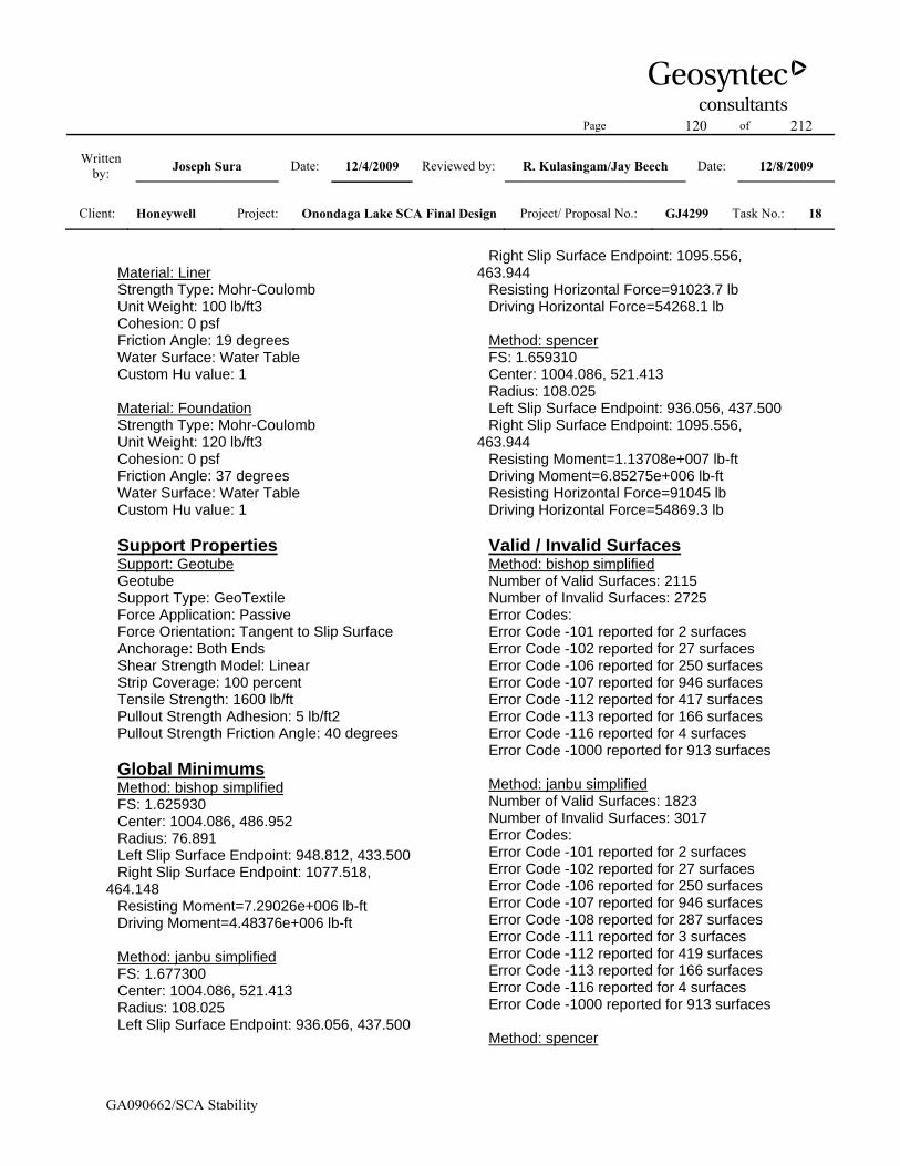
Page 120 of 212
Written by: Joseph Sura Date: 12/4/2009 Reviewed by: R. Kulasingam/Jay Beech Date: 12/8/2009
Client: Honeywell Project: Onondaga Lake SCA Final Design Project/ Proposal No.: GJ4299 Task No.: 18
GA090662/SCA Stability
Material: Liner Strength Type: Mohr-Coulomb Unit Weight: 100 lb/ft3 Cohesion: 0 psf Friction Angle: 19 degrees Water Surface: Water Table Custom Hu value: 1 Material: Foundation Strength Type: Mohr-Coulomb Unit Weight: 120 lb/ft3 Cohesion: 0 psf Friction Angle: 37 degrees Water Surface: Water Table Custom Hu value: 1 Support Properties Support: Geotube Geotube Support Type: GeoTextile Force Application: Passive Force Orientation: Tangent to Slip Surface Anchorage: Both Ends Shear Strength Model: Linear Strip Coverage: 100 percent Tensile Strength: 1600 lb/ft Pullout Strength Adhesion: 5 lb/ft2 Pullout Strength Friction Angle: 40 degrees Global Minimums Method: bishop simplified FS: 1.625930 Center: 1004.086, 486.952 Radius: 76.891 Left Slip Surface Endpoint: 948.812, 433.500 Right Slip Surface Endpoint: 1077.518, 464.148 Resisting Moment=7.29026e+006 lb-ft Driving Moment=4.48376e+006 lb-ft Method: janbu simplified FS: 1.677300 Center: 1004.086, 521.413 Radius: 108.025 Left Slip Surface Endpoint: 936.056, 437.500
Right Slip Surface Endpoint: 1095.556, 463.944 Resisting Horizontal Force=91023.7 lb Driving Horizontal Force=54268.1 lb Method: spencer FS: 1.659310 Center: 1004.086, 521.413 Radius: 108.025 Left Slip Surface Endpoint: 936.056, 437.500 Right Slip Surface Endpoint: 1095.556, 463.944 Resisting Moment=1.13708e+007 lb-ft Driving Moment=6.85275e+006 lb-ft Resisting Horizontal Force=91045 lb Driving Horizontal Force=54869.3 lb Valid / Invalid Surfaces Method: bishop simplified Number of Valid Surfaces: 2115 Number of Invalid Surfaces: 2725 Error Codes: Error Code -101 reported for 2 surfaces Error Code -102 reported for 27 surfaces Error Code -106 reported for 250 surfaces Error Code -107 reported for 946 surfaces Error Code -112 reported for 417 surfaces Error Code -113 reported for 166 surfaces Error Code -116 reported for 4 surfaces Error Code -1000 reported for 913 surfaces Method: janbu simplified Number of Valid Surfaces: 1823 Number of Invalid Surfaces: 3017 Error Codes: Error Code -101 reported for 2 surfaces Error Code -102 reported for 27 surfaces Error Code -106 reported for 250 surfaces Error Code -107 reported for 946 surfaces Error Code -108 reported for 287 surfaces Error Code -111 reported for 3 surfaces Error Code -112 reported for 419 surfaces Error Code -113 reported for 166 surfaces Error Code -116 reported for 4 surfaces Error Code -1000 reported for 913 surfaces Method: spencer
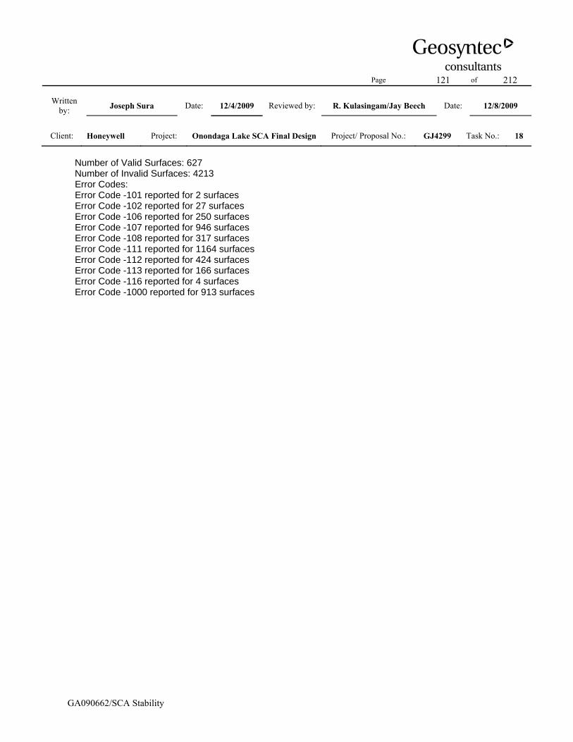
Page 121 of 212
Written by: Joseph Sura Date: 12/4/2009 Reviewed by: R. Kulasingam/Jay Beech Date: 12/8/2009
Client: Honeywell Project: Onondaga Lake SCA Final Design Project/ Proposal No.: GJ4299 Task No.: 18
GA090662/SCA Stability
Number of Valid Surfaces: 627 Number of Invalid Surfaces: 4213 Error Codes: Error Code -101 reported for 2 surfaces Error Code -102 reported for 27 surfaces Error Code -106 reported for 250 surfaces Error Code -107 reported for 946 surfaces Error Code -108 reported for 317 surfaces Error Code -111 reported for 1164 surfaces Error Code -112 reported for 424 surfaces Error Code -113 reported for 166 surfaces Error Code -116 reported for 4 surfaces Error Code -1000 reported for 913 surfaces

Page 122 of 212
Written by: Joseph Sura Date: 12/4/2009 Reviewed by: R. Kulasingam/Jay Beech Date: 12/8/2009
Client: Honeywell Project: Onondaga Lake SCA Final Design Project/ Proposal No.: GJ4299 Task No.: 18
GA090662/SCA Stability
Slide Analysis Information Document Name File Name: northside_nocover_external_lab Project Settings Project Title: SLIDE - An Interactive Slope Stability Program Failure Direction: Right to Left Units of Measurement: Imperial Units Pore Fluid Unit Weight: 62.4 lb/ft3 Groundwater Method: Water Surfaces Data Output: Standard Calculate Excess Pore Pressure: Off Allow Ru with Water Surfaces or Grids: Off Random Numbers: Pseudo-random Seed Random Number Seed: 10116 Random Number Generation Method: Park and Miller v.3 Analysis Methods Analysis Methods used: Bishop simplified Janbu simplified Spencer Number of slices: 25 Tolerance: 0.005 Maximum number of iterations: 50 Surface Options Surface Type: Circular Search Method: Grid Search Radius increment: 10 Composite Surfaces: Disabled Reverse Curvature: Create Tension Crack Minimum Elevation: Not Defined Minimum Depth: Not Defined Material Properties Material: Dike Soil Strength Type: Mohr-Coulomb Unit Weight: 120 lb/ft3 Cohesion: 0 psf Friction Angle: 35 degrees
Water Surface: Water Table Custom Hu value: 1 Material: Gravel Strength Type: Mohr-Coulomb Unit Weight: 120 lb/ft3 Cohesion: 0 psf Friction Angle: 38 degrees Water Surface: Piezometric Line 1 Custom Hu value: 1 Material: SOLW (undrained) Strength Type: Discrete function Unit Weight: 82 lb/ft3 Water Surface: Water Table Custom Hu value: 1 Material: Dredge Material Strength Type: Mohr-Coulomb Unit Weight: 86 lb/ft3 Cohesion: 0 psf Friction Angle: 15 degrees Water Surface: Water Table Custom Hu value: 1 Material: Tube-Tube Interface (Horizontal) Strength Type: Mohr-Coulomb Unit Weight: 86 lb/ft3 Cohesion: 0 psf Friction Angle: 15 degrees Water Surface: Water Table Custom Hu value: 1 Material: Tub-Tube Interface (Vertical) Strength Type: Mohr-Coulomb Unit Weight: 43 lb/ft3 Cohesion: 0 psf Friction Angle: 0.1 degrees Water Surface: Water Table Custom Hu value: 1 Material: Tube-Gravel Interface Strength Type: Mohr-Coulomb Unit Weight: 86 lb/ft3 Cohesion: 0 psf Friction Angle: 24 degrees Water Surface: Water Table Custom Hu value: 1
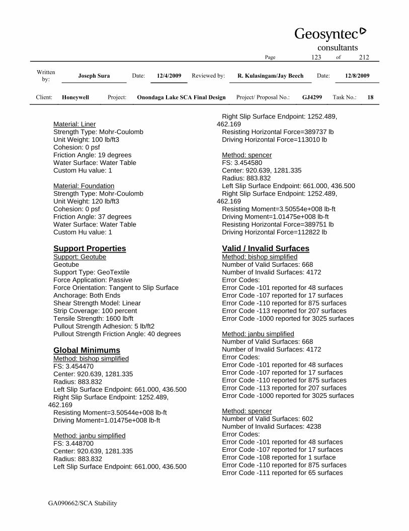
Page 123 of 212
Written by: Joseph Sura Date: 12/4/2009 Reviewed by: R. Kulasingam/Jay Beech Date: 12/8/2009
Client: Honeywell Project: Onondaga Lake SCA Final Design Project/ Proposal No.: GJ4299 Task No.: 18
GA090662/SCA Stability
Material: Liner Strength Type: Mohr-Coulomb Unit Weight: 100 lb/ft3 Cohesion: 0 psf Friction Angle: 19 degrees Water Surface: Water Table Custom Hu value: 1 Material: Foundation Strength Type: Mohr-Coulomb Unit Weight: 120 lb/ft3 Cohesion: 0 psf Friction Angle: 37 degrees Water Surface: Water Table Custom Hu value: 1 Support Properties Support: Geotube Geotube Support Type: GeoTextile Force Application: Passive Force Orientation: Tangent to Slip Surface Anchorage: Both Ends Shear Strength Model: Linear Strip Coverage: 100 percent Tensile Strength: 1600 lb/ft Pullout Strength Adhesion: 5 lb/ft2 Pullout Strength Friction Angle: 40 degrees Global Minimums Method: bishop simplified FS: 3.454470 Center: 920.639, 1281.335 Radius: 883.832 Left Slip Surface Endpoint: 661.000, 436.500 Right Slip Surface Endpoint: 1252.489, 462.169 Resisting Moment=3.50544e+008 lb-ft Driving Moment=1.01475e+008 lb-ft Method: janbu simplified FS: 3.448700 Center: 920.639, 1281.335 Radius: 883.832 Left Slip Surface Endpoint: 661.000, 436.500
Right Slip Surface Endpoint: 1252.489, 462.169 Resisting Horizontal Force=389737 lb Driving Horizontal Force=113010 lb Method: spencer FS: 3.454580 Center: 920.639, 1281.335 Radius: 883.832 Left Slip Surface Endpoint: 661.000, 436.500 Right Slip Surface Endpoint: 1252.489, 462.169 Resisting Moment=3.50554e+008 lb-ft Driving Moment=1.01475e+008 lb-ft Resisting Horizontal Force=389751 lb Driving Horizontal Force=112822 lb Valid / Invalid Surfaces Method: bishop simplified Number of Valid Surfaces: 668 Number of Invalid Surfaces: 4172 Error Codes: Error Code -101 reported for 48 surfaces Error Code -107 reported for 17 surfaces Error Code -110 reported for 875 surfaces Error Code -113 reported for 207 surfaces Error Code -1000 reported for 3025 surfaces Method: janbu simplified Number of Valid Surfaces: 668 Number of Invalid Surfaces: 4172 Error Codes: Error Code -101 reported for 48 surfaces Error Code -107 reported for 17 surfaces Error Code -110 reported for 875 surfaces Error Code -113 reported for 207 surfaces Error Code -1000 reported for 3025 surfaces Method: spencer Number of Valid Surfaces: 602 Number of Invalid Surfaces: 4238 Error Codes: Error Code -101 reported for 48 surfaces Error Code -107 reported for 17 surfaces Error Code -108 reported for 1 surface Error Code -110 reported for 875 surfaces Error Code -111 reported for 65 surfaces

Page 124 of 212
Written by: Joseph Sura Date: 12/4/2009 Reviewed by: R. Kulasingam/Jay Beech Date: 12/8/2009
Client: Honeywell Project: Onondaga Lake SCA Final Design Project/ Proposal No.: GJ4299 Task No.: 18
GA090662/SCA Stability
Error Code -113 reported for 207 surfaces Error Code -1000 reported for 3025 surfaces

Page 125 of 212
Written by: Joseph Sura Date: 12/4/2009 Reviewed by: R. Kulasingam/Jay Beech Date: 12/8/2009
Client: Honeywell Project: Onondaga Lake SCA Final Design Project/ Proposal No.: GJ4299 Task No.: 18
GA090662/SCA Stability
Cross-Section A-A: After Placement of Final Cover

Page 126 of 212
Written by: Joseph Sura Date: 12/4/2009 Reviewed by: R. Kulasingam/Jay Beech Date: 12/8/2009
Client: Honeywell Project: Onondaga Lake SCA Final Design Project/ Proposal No.: GJ4299 Task No.: 18
GA090662/SCA Stability
Slide Analysis Information Document Name File Name: northside_cover_tube_07_lab Project Settings Project Title: SLIDE - An Interactive Slope Stability Program Failure Direction: Right to Left Units of Measurement: Imperial Units Pore Fluid Unit Weight: 62.4 lb/ft3 Groundwater Method: Water Surfaces Data Output: Standard Calculate Excess Pore Pressure: Off Allow Ru with Water Surfaces or Grids: Off Random Numbers: Pseudo-random Seed Random Number Seed: 10116 Random Number Generation Method: Park and Miller v.3 Analysis Methods Analysis Methods used: Bishop simplified Janbu simplified Spencer Number of slices: 25 Tolerance: 0.005 Maximum number of iterations: 50 Surface Options Surface Type: Non-Circular Block Search Number of Surfaces: 5000 Pseudo-Random Surfaces: Enabled Convex Surfaces Only: Disabled Left Projection Angle (Start Angle): 95 Left Projection Angle (End Angle): 175 Right Projection Angle (Start Angle): 5 Right Projection Angle (End Angle): 85 Minimum Elevation: Not Defined Minimum Depth: Not Defined Material Properties Material: Final Cover Soil
Strength Type: Mohr-Coulomb Unit Weight: 120 lb/ft3 Cohesion: 0 psf Friction Angle: 30 degrees Water Surface: Water Table Custom Hu value: 1 Material: Dike Soil Strength Type: Mohr-Coulomb Unit Weight: 120 lb/ft3 Cohesion: 0 psf Friction Angle: 35 degrees Water Surface: Water Table Custom Hu value: 1 Material: Gravel Strength Type: Mohr-Coulomb Unit Weight: 120 lb/ft3 Cohesion: 0 psf Friction Angle: 38 degrees Water Surface: Piezometric Line 1 Custom Hu value: 1 Material: SOLW (undrained) Strength Type: Discrete function Unit Weight: 82 lb/ft3 Water Surface: Water Table Custom Hu value: 1 Material: Dredge Material Strength Type: Mohr-Coulomb Unit Weight: 86 lb/ft3 Cohesion: 0 psf Friction Angle: 15 degrees Water Surface: Water Table Custom Hu value: 1 Material: Tube-Tube Interface (Horizontal) Strength Type: Mohr-Coulomb Unit Weight: 86 lb/ft3 Cohesion: 0 psf Friction Angle: 15 degrees Water Surface: Water Table Custom Hu value: 1 Material: Tub-Tube Interface (Vertical) Strength Type: Mohr-Coulomb Unit Weight: 43 lb/ft3

Page 127 of 212
Written by: Joseph Sura Date: 12/4/2009 Reviewed by: R. Kulasingam/Jay Beech Date: 12/8/2009
Client: Honeywell Project: Onondaga Lake SCA Final Design Project/ Proposal No.: GJ4299 Task No.: 18
GA090662/SCA Stability
Cohesion: 0 psf Friction Angle: 0.1 degrees Water Surface: Water Table Custom Hu value: 1 Material: Tube-Gravel Interface Strength Type: Mohr-Coulomb Unit Weight: 86 lb/ft3 Cohesion: 0 psf Friction Angle: 24 degrees Water Surface: Water Table Custom Hu value: 1 Material: Liner Strength Type: Mohr-Coulomb Unit Weight: 100 lb/ft3 Cohesion: 0 psf Friction Angle: 19 degrees Water Surface: Water Table Custom Hu value: 1 Material: Foundation Strength Type: Mohr-Coulomb Unit Weight: 120 lb/ft3 Cohesion: 0 psf Friction Angle: 37 degrees Water Surface: Water Table Custom Hu value: 1 Support Properties Support: Geotube Geotube Support Type: GeoTextile Force Application: Passive Force Orientation: Tangent to Slip Surface Anchorage: Both Ends Shear Strength Model: Linear Strip Coverage: 100 percent Tensile Strength: 1600 lb/ft Pullout Strength Adhesion: 5 lb/ft2 Pullout Strength Friction Angle: 40 degrees Global Minimums Method: bishop simplified FS: 1.673550 Axis Location: 994.617, 580.470 Left Slip Surface Endpoint: 955.538, 443.647
Right Slip Surface Endpoint: 1080.628, 467.113 Resisting Moment=5.65391e+006 lb-ft Driving Moment=3.3784e+006 lb-ft Method: janbu simplified FS: 1.616810 Axis Location: 996.469, 578.457 Left Slip Surface Endpoint: 957.879, 444.337 Right Slip Surface Endpoint: 1080.610, 467.113 Resisting Horizontal Force=41178.9 lb Driving Horizontal Force=25469.3 lb Method: spencer FS: 2.508240 Axis Location: 1016.759, 590.998 Left Slip Surface Endpoint: 969.101, 447.648 Right Slip Surface Endpoint: 1102.844, 466.861 Resisting Moment=6.28706e+006 lb-ft Driving Moment=2.50656e+006 lb-ft Resisting Horizontal Force=42923.8 lb Driving Horizontal Force=17113.1 lb Valid / Invalid Surfaces Method: bishop simplified Number of Valid Surfaces: 4114 Number of Invalid Surfaces: 886 Error Codes: Error Code -107 reported for 59 surfaces Error Code -108 reported for 226 surfaces Error Code -111 reported for 21 surfaces Error Code -112 reported for 580 surfaces Method: janbu simplified Number of Valid Surfaces: 4036 Number of Invalid Surfaces: 964 Error Codes: Error Code -107 reported for 59 surfaces Error Code -108 reported for 241 surfaces Error Code -111 reported for 49 surfaces Error Code -112 reported for 615 surfaces Method: spencer Number of Valid Surfaces: 2849 Number of Invalid Surfaces: 2151

Page 128 of 212
Written by: Joseph Sura Date: 12/4/2009 Reviewed by: R. Kulasingam/Jay Beech Date: 12/8/2009
Client: Honeywell Project: Onondaga Lake SCA Final Design Project/ Proposal No.: GJ4299 Task No.: 18
GA090662/SCA Stability
Error Codes: Error Code -107 reported for 59 surfaces Error Code -108 reported for 1358 surfaces Error Code -111 reported for 95 surfaces Error Code -112 reported for 639 surfaces List of All Coordinates Block Search Polyline 978.000 441.278 1017.040 441.054 Material Boundary 953.000 433.500 958.000 433.500 1400.000 427.700 Material Boundary 978.000 441.524 997.000 441.309 998.500 441.292 1017.009 441.083 1018.508 441.066 1037.000 440.856 1038.500 440.839 1057.015 440.630 1058.509 440.613 1096.999 440.178 1098.506 440.161 1117.012 439.951 1118.512 439.934 1137.006 439.725 1138.505 439.708 1157.006 439.499 1158.500 439.482 1176.999 439.273 1178.492 439.256 1197.013 439.046 1198.512 439.029 1217.005 438.820 1218.499 438.803 1237.000 438.594 1238.506 438.577 1257.010 438.368 1258.509 438.351 1277.013 438.141 1278.513 438.124 1296.975 437.915
1298.469 437.899 1317.013 437.689 1318.507 437.672 1336.969 437.463 1338.469 437.446 1357.000 437.236 1358.510 437.219 1376.969 437.011 1378.475 436.993 1400.000 436.750 Material Boundary 998.000 447.048 1017.014 446.832 1018.514 446.815 1037.015 446.606 1038.521 446.589 1057.021 446.380 1058.520 446.363 1077.016 446.154 1078.515 446.137 1097.005 445.928 1098.523 445.910 1117.022 445.701 1118.509 445.684 1137.023 445.475 1138.511 445.458 1157.009 445.249 1158.509 445.232 1177.011 445.023 1178.494 445.006 1197.022 444.796 1198.509 444.779 1217.011 444.570 1218.511 444.553 1237.016 444.344 1238.509 444.327 1257.015 444.117 1258.515 444.101 1277.009 443.891 1278.515 443.874 1296.975 443.665 1298.475 443.648 1317.016 443.439 1318.515 443.422 1336.981 443.213 1338.481 443.196 1357.016 442.986

Page 129 of 212
Written by: Joseph Sura Date: 12/4/2009 Reviewed by: R. Kulasingam/Jay Beech Date: 12/8/2009
Client: Honeywell Project: Onondaga Lake SCA Final Design Project/ Proposal No.: GJ4299 Task No.: 18
GA090662/SCA Stability
1358.516 442.969 1376.981 442.760 1378.481 442.743 1400.000 442.500 Material Boundary 998.000 447.298 1017.014 447.082 1018.514 447.066 1037.016 446.856 1038.521 446.839 1057.021 446.630 1058.521 446.613 1077.016 446.404 1078.516 446.387 1097.005 446.178 1098.524 446.160 1117.022 445.951 1118.510 445.934 1137.024 445.725 1138.511 445.708 1157.010 445.499 1158.510 445.482 1177.011 445.273 1178.494 445.256 1197.022 445.046 1198.510 445.029 1217.011 444.820 1218.511 444.803 1237.016 444.594 1238.509 444.577 1257.016 444.368 1258.515 444.351 1277.010 444.141 1278.516 444.124 1296.975 443.915 1298.475 443.898 1317.016 443.689 1318.516 443.672 1336.981 443.463 1338.481 443.446 1357.016 443.236 1358.516 443.219 1376.981 443.010 1378.481 442.993 1400.000 442.750 Material Boundary
1018.000 452.821 1037.021 452.606 1038.521 452.589 1057.007 452.380 1058.501 452.363 1077.021 452.154 1078.527 452.137 1096.995 451.928 1098.501 451.911 1117.028 451.701 1118.527 451.684 1137.001 451.475 1138.501 451.458 1157.027 451.249 1158.521 451.232 1176.995 451.023 1178.495 451.006 1197.028 450.796 1198.521 450.779 1217.001 450.570 1218.501 450.553 1237.022 450.344 1238.515 450.327 1257.007 450.118 1258.501 450.101 1277.021 449.891 1278.521 449.874 1297.001 449.665 1298.501 449.648 1317.028 449.439 1318.521 449.422 1337.008 449.213 1338.501 449.196 1357.022 448.986 1358.521 448.969 1377.008 448.760 1378.508 448.743 1400.000 448.500 Material Boundary 1018.000 453.071 1037.022 452.856 1038.521 452.839 1057.007 452.630 1058.501 452.613 1077.022 452.404 1078.528 452.387 1096.996 452.178

Page 130 of 212
Written by: Joseph Sura Date: 12/4/2009 Reviewed by: R. Kulasingam/Jay Beech Date: 12/8/2009
Client: Honeywell Project: Onondaga Lake SCA Final Design Project/ Proposal No.: GJ4299 Task No.: 18
GA090662/SCA Stability
1098.501 452.161 1117.028 451.951 1118.528 451.934 1137.002 451.725 1138.501 451.708 1157.028 451.499 1158.522 451.482 1176.996 451.273 1178.496 451.256 1197.028 451.046 1198.522 451.029 1217.001 450.820 1218.501 450.803 1237.022 450.594 1238.515 450.577 1257.007 450.368 1258.501 450.351 1277.022 450.141 1278.522 450.124 1297.002 449.915 1298.502 449.898 1317.028 449.689 1318.522 449.672 1337.008 449.463 1338.502 449.446 1357.022 449.236 1358.522 449.219 1377.008 449.010 1378.508 448.993 1400.000 448.750 Material Boundary 1038.000 458.595 1057.013 458.380 1058.512 458.363 1077.005 458.154 1078.505 458.137 1097.013 457.928 1098.513 457.911 1117.011 457.701 1118.498 457.685 1137.019 457.475 1138.507 457.458 1157.005 457.249 1158.498 457.232 1177.013 457.023 1178.518 457.006 1197.005 456.796
1198.498 456.779 1217.007 456.570 1218.501 456.553 1237.005 456.344 1238.511 456.327 1257.007 456.118 1258.507 456.101 1277.005 455.891 1278.505 455.874 1297.013 455.665 1298.513 455.648 1317.005 455.439 1318.505 455.422 1337.014 455.213 1338.507 455.196 1357.006 454.986 1358.511 454.969 1377.021 454.760 1378.513 454.743 1400.000 454.500 Material Boundary 1038.000 458.845 1057.013 458.630 1058.513 458.613 1077.006 458.404 1078.505 458.387 1097.013 458.178 1098.513 458.161 1117.011 457.951 1118.499 457.934 1137.020 457.725 1138.507 457.708 1157.005 457.499 1158.499 457.482 1177.013 457.273 1178.519 457.255 1197.006 457.046 1198.499 457.029 1217.007 456.820 1218.501 456.803 1237.006 456.594 1238.511 456.577 1257.007 456.368 1258.507 456.351 1277.005 456.141 1278.505 456.124 1297.014 455.915

Page 131 of 212
Written by: Joseph Sura Date: 12/4/2009 Reviewed by: R. Kulasingam/Jay Beech Date: 12/8/2009
Client: Honeywell Project: Onondaga Lake SCA Final Design Project/ Proposal No.: GJ4299 Task No.: 18
GA090662/SCA Stability
1298.514 455.898 1317.005 455.689 1318.505 455.672 1337.014 455.463 1338.507 455.446 1357.006 455.236 1358.511 455.219 1377.021 455.010 1378.514 454.993 1400.000 454.750 Material Boundary 958.000 435.500 997.000 435.059 998.500 435.042 1037.000 434.606 1038.494 434.589 1077.000 434.154 1078.500 434.137 1117.000 433.701 1118.494 433.684 1156.994 433.249 1158.494 433.232 1197.006 432.796 1198.500 432.779 1236.994 432.344 1238.494 432.327 1277.007 431.891 1278.507 431.874 1317.007 431.439 1318.507 431.422 1357.000 430.986 1358.499 430.969 1400.000 430.500 Material Boundary 978.000 441.274 997.000 441.059 998.500 441.042 1017.008 440.832 1018.508 440.816 1037.000 440.606 1038.500 440.589 1057.015 440.380 1058.508 440.363 1077.006 440.154 1078.494 440.137 1096.999 439.928
1098.505 439.911 1117.012 439.701 1118.511 439.684 1137.005 439.475 1138.505 439.458 1157.006 439.249 1158.500 439.232 1176.999 439.023 1178.492 439.006 1197.012 438.796 1198.512 438.779 1217.005 438.570 1218.499 438.553 1237.000 438.344 1238.506 438.327 1257.009 438.118 1258.509 438.101 1277.013 437.891 1278.512 437.874 1296.975 437.665 1298.469 437.649 1317.013 437.439 1318.507 437.422 1336.969 437.213 1338.469 437.196 1357.000 436.986 1358.510 436.969 1376.969 436.761 1378.475 436.743 1400.000 436.500 Material Boundary 958.000 435.750 997.000 435.309 998.500 435.292 1037.000 434.856 1038.494 434.839 1077.000 434.404 1078.500 434.387 1117.001 433.951 1118.494 433.934 1156.994 433.499 1158.494 433.482 1197.007 433.046 1198.500 433.029 1236.994 432.594 1238.494 432.577 1277.007 432.141
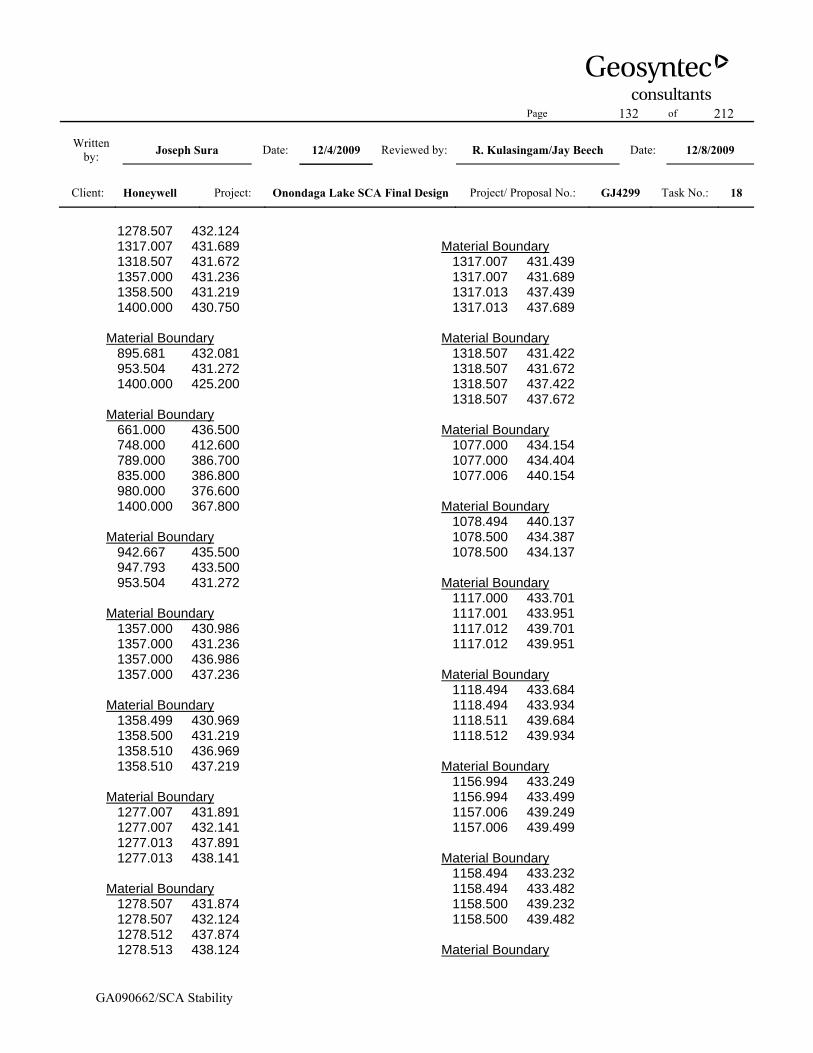
Page 132 of 212
Written by: Joseph Sura Date: 12/4/2009 Reviewed by: R. Kulasingam/Jay Beech Date: 12/8/2009
Client: Honeywell Project: Onondaga Lake SCA Final Design Project/ Proposal No.: GJ4299 Task No.: 18
GA090662/SCA Stability
1278.507 432.124 1317.007 431.689 1318.507 431.672 1357.000 431.236 1358.500 431.219 1400.000 430.750 Material Boundary 895.681 432.081 953.504 431.272 1400.000 425.200 Material Boundary 661.000 436.500 748.000 412.600 789.000 386.700 835.000 386.800 980.000 376.600 1400.000 367.800 Material Boundary 942.667 435.500 947.793 433.500 953.504 431.272 Material Boundary 1357.000 430.986 1357.000 431.236 1357.000 436.986 1357.000 437.236 Material Boundary 1358.499 430.969 1358.500 431.219 1358.510 436.969 1358.510 437.219 Material Boundary 1277.007 431.891 1277.007 432.141 1277.013 437.891 1277.013 438.141 Material Boundary 1278.507 431.874 1278.507 432.124 1278.512 437.874 1278.513 438.124
Material Boundary 1317.007 431.439 1317.007 431.689 1317.013 437.439 1317.013 437.689 Material Boundary 1318.507 431.422 1318.507 431.672 1318.507 437.422 1318.507 437.672 Material Boundary 1077.000 434.154 1077.000 434.404 1077.006 440.154 Material Boundary 1078.494 440.137 1078.500 434.387 1078.500 434.137 Material Boundary 1117.000 433.701 1117.001 433.951 1117.012 439.701 1117.012 439.951 Material Boundary 1118.494 433.684 1118.494 433.934 1118.511 439.684 1118.512 439.934 Material Boundary 1156.994 433.249 1156.994 433.499 1157.006 439.249 1157.006 439.499 Material Boundary 1158.494 433.232 1158.494 433.482 1158.500 439.232 1158.500 439.482 Material Boundary

Page 133 of 212
Written by: Joseph Sura Date: 12/4/2009 Reviewed by: R. Kulasingam/Jay Beech Date: 12/8/2009
Client: Honeywell Project: Onondaga Lake SCA Final Design Project/ Proposal No.: GJ4299 Task No.: 18
GA090662/SCA Stability
1197.006 432.796 1197.007 433.046 1197.012 438.796 1197.013 439.046 Material Boundary 1198.500 432.779 1198.500 433.029 1198.512 438.779 1198.512 439.029 Material Boundary 1236.994 432.344 1236.994 432.594 1237.000 438.344 1237.000 438.594 Material Boundary 1238.494 432.327 1238.494 432.577 1238.506 438.327 1238.506 438.577 Material Boundary 997.000 435.059 997.000 435.309 997.000 441.059 997.000 441.309 Material Boundary 998.500 435.042 998.500 435.292 998.500 441.042 998.500 441.292 Material Boundary 1037.000 434.606 1037.000 434.856 1037.000 440.606 1037.000 440.856 Material Boundary 1038.494 434.589 1038.494 434.839 1038.500 440.589 1038.500 440.839 Material Boundary
1296.975 437.665 1296.975 437.915 1296.975 443.665 1296.975 443.915 Material Boundary 1298.469 437.649 1298.469 437.899 1298.475 443.648 1298.475 443.898 Material Boundary 1336.969 437.213 1336.969 437.463 1336.981 443.213 1336.981 443.463 Material Boundary 1338.469 437.196 1338.469 437.446 1338.481 443.196 1338.481 443.446 Material Boundary 1376.969 436.761 1376.969 437.011 1376.981 442.760 1376.981 443.010 Material Boundary 1378.475 436.743 1378.475 436.993 1378.481 442.743 1378.481 442.993 Material Boundary 1257.009 438.118 1257.010 438.368 1257.015 444.117 1257.016 444.368 Material Boundary 1258.509 438.101 1258.509 438.351 1258.515 444.101 1258.515 444.351 Material Boundary

Page 134 of 212
Written by: Joseph Sura Date: 12/4/2009 Reviewed by: R. Kulasingam/Jay Beech Date: 12/8/2009
Client: Honeywell Project: Onondaga Lake SCA Final Design Project/ Proposal No.: GJ4299 Task No.: 18
GA090662/SCA Stability
1096.999 439.928 1096.999 440.178 1097.005 445.928 1097.005 446.178 Material Boundary 1098.505 439.911 1098.506 440.161 1098.523 445.910 1098.524 446.160 Material Boundary 1137.005 439.475 1137.006 439.725 1137.023 445.475 1137.024 445.725 Material Boundary 1138.505 439.458 1138.505 439.708 1138.511 445.458 1138.511 445.708 Material Boundary 1176.999 439.023 1176.999 439.273 1177.011 445.023 1177.011 445.273 Material Boundary 1178.492 439.006 1178.492 439.256 1178.494 445.006 1178.494 445.256 Material Boundary 1217.005 438.570 1217.005 438.820 1217.011 444.570 1217.011 444.820 Material Boundary 1218.499 438.553 1218.499 438.803 1218.511 444.553 1218.511 444.803 Material Boundary
1017.008 440.832 1017.009 441.083 1017.014 446.832 1017.014 447.082 Material Boundary 1018.508 440.816 1018.508 441.066 1018.514 446.815 1018.514 447.066 Material Boundary 1057.015 440.380 1057.015 440.630 1057.021 446.380 1057.021 446.630 Material Boundary 1058.508 440.363 1058.509 440.613 1058.520 446.363 1058.521 446.613 Material Boundary 1037.015 446.606 1037.016 446.856 1037.021 452.606 1037.022 452.856 Material Boundary 1038.521 446.589 1038.521 446.839 1038.521 452.589 1038.521 452.839 Material Boundary 1077.016 446.154 1077.016 446.404 1077.021 452.154 1077.022 452.404 Material Boundary 1078.515 446.137 1078.516 446.387 1078.527 452.137 1078.528 452.387 Material Boundary
Page 135 of 212
Written by: Joseph Sura Date: 12/4/2009 Reviewed by: R. Kulasingam/Jay Beech Date: 12/8/2009
Client: Honeywell Project: Onondaga Lake SCA Final Design Project/ Proposal No.: GJ4299 Task No.: 18
GA090662/SCA Stability
1117.022 445.701 1117.022 445.951 1117.028 451.701 1117.028 451.951 Material Boundary 1118.509 445.684 1118.510 445.934 1118.527 451.684 1118.528 451.934 Material Boundary 1157.009 445.249 1157.010 445.499 1157.027 451.249 1157.028 451.499 Material Boundary 1158.509 445.232 1158.510 445.482 1158.521 451.232 1158.522 451.482 Material Boundary 1197.022 444.796 1197.022 445.046 1197.028 450.796 1197.028 451.046 Material Boundary 1198.509 444.779 1198.510 445.029 1198.521 450.779 1198.522 451.029 Material Boundary 1237.016 444.344 1237.016 444.594 1237.022 450.344 1237.022 450.594 Material Boundary 1238.509 444.327 1238.509 444.577 1238.515 450.327 1238.515 450.577 Material Boundary
1277.009 443.891 1277.010 444.141 1277.021 449.891 1277.022 450.141 Material Boundary 1278.515 443.874 1278.516 444.124 1278.521 449.874 1278.522 450.124 Material Boundary 1317.016 443.439 1317.016 443.689 1317.028 449.439 1317.028 449.689 Material Boundary 1318.515 443.422 1318.516 443.672 1318.521 449.422 1318.522 449.672 Material Boundary 1357.016 442.986 1357.016 443.236 1357.022 448.986 1357.022 449.236 Material Boundary 1358.516 442.969 1358.516 443.219 1358.521 448.969 1358.522 449.219 Material Boundary 1057.007 452.380 1057.007 452.630 1057.013 458.380 1057.013 458.630 Material Boundary 1058.501 452.363 1058.501 452.613 1058.512 458.363 1058.513 458.613 Material Boundary

Page 136 of 212
Written by: Joseph Sura Date: 12/4/2009 Reviewed by: R. Kulasingam/Jay Beech Date: 12/8/2009
Client: Honeywell Project: Onondaga Lake SCA Final Design Project/ Proposal No.: GJ4299 Task No.: 18
GA090662/SCA Stability
1098.501 451.911 1098.501 452.161 1098.513 457.911 1098.513 458.161 Material Boundary 1096.995 451.928 1096.996 452.178 1097.013 457.928 1097.013 458.178 Material Boundary 1137.001 451.475 1137.002 451.725 1137.019 457.475 1137.020 457.725 Material Boundary 1138.501 451.458 1138.501 451.708 1138.507 457.458 1138.507 457.708 Material Boundary 1176.995 451.023 1176.996 451.273 1177.013 457.023 1177.013 457.273 Material Boundary 1178.495 451.006 1178.496 451.256 1178.518 457.006 1178.519 457.255 Material Boundary 1217.001 450.570 1217.001 450.820 1217.007 456.570 1217.007 456.820 Material Boundary 1218.501 450.553 1218.501 450.803 1218.501 456.553 1218.501 456.803 Material Boundary
1257.007 450.118 1257.007 450.368 1257.007 456.118 1257.007 456.368 Material Boundary 1258.501 450.101 1258.501 450.351 1258.507 456.101 1258.507 456.351 Material Boundary 1297.001 449.665 1297.002 449.915 1297.013 455.665 1297.014 455.915 Material Boundary 1298.501 449.648 1298.502 449.898 1298.513 455.648 1298.514 455.898 Material Boundary 1337.008 449.213 1337.008 449.463 1337.014 455.213 1337.014 455.463 Material Boundary 1338.501 449.196 1338.502 449.446 1338.507 455.196 1338.507 455.446 Material Boundary 1377.008 448.760 1377.008 449.010 1377.021 454.760 1377.021 455.010 Material Boundary 1378.508 448.743 1378.508 448.993 1378.513 454.743 1378.514 454.993 Material Boundary

Page 137 of 212
Written by: Joseph Sura Date: 12/4/2009 Reviewed by: R. Kulasingam/Jay Beech Date: 12/8/2009
Client: Honeywell Project: Onondaga Lake SCA Final Design Project/ Proposal No.: GJ4299 Task No.: 18
GA090662/SCA Stability
1077.005 458.154 1077.006 458.404 1077.017 464.154 Material Boundary 1078.505 458.137 1078.505 458.387 1078.517 464.137 Material Boundary 1117.011 457.701 1117.011 457.951 1117.011 463.701 Material Boundary 1118.498 457.685 1118.499 457.934 1118.511 463.684 Material Boundary 1157.005 457.249 1157.005 457.499 1157.011 463.249 Material Boundary 1158.498 457.232 1158.499 457.482 1158.511 463.232 Material Boundary 1197.005 456.796 1197.006 457.046 1197.017 462.796 Material Boundary 1198.498 456.779 1198.499 457.029 1198.517 462.779 Material Boundary 1237.005 456.344 1237.006 456.594 1237.024 462.344 Material Boundary 1238.511 456.327 1238.511 456.577 1238.517 462.327
Material Boundary 1277.005 455.891 1277.005 456.141 1277.011 461.891 Material Boundary 1278.505 455.874 1278.505 456.124 1278.505 461.874 Material Boundary 1317.005 455.439 1317.005 455.689 1317.011 461.439 Material Boundary 1318.505 455.422 1318.505 455.672 1318.517 461.422 Material Boundary 1357.006 454.986 1357.006 455.236 1357.017 460.986 Material Boundary 1358.511 454.969 1358.511 455.219 1358.511 460.969 Material Boundary 937.818 437.500 940.000 436.600 942.667 435.500 Material Boundary 934.712 437.500 937.818 437.500 938.818 437.500 941.000 436.600 943.667 435.500 948.793 433.500 953.000 433.500 955.504 434.501 958.000 435.500 958.000 435.750 958.000 441.500

Page 138 of 212
Written by: Joseph Sura Date: 12/4/2009 Reviewed by: R. Kulasingam/Jay Beech Date: 12/8/2009
Client: Honeywell Project: Onondaga Lake SCA Final Design Project/ Proposal No.: GJ4299 Task No.: 18
GA090662/SCA Stability
978.000 441.274 978.000 441.524 978.000 447.274 998.000 447.048 998.000 447.298 998.000 453.048 1018.000 452.821 1018.000 453.071 1018.000 458.821 1038.000 458.595 1038.000 458.845 1038.000 464.595 1077.017 464.154 1078.517 464.137 1117.011 463.701 1118.511 463.684 1157.011 463.249 1158.511 463.232 1197.017 462.796 1198.517 462.779 1237.024 462.344 1238.517 462.327 1277.011 461.891 1278.505 461.874 1317.011 461.439 1318.517 461.422 1357.017 460.986 1358.511 460.969 1400.000 460.500 External Boundary 934.712 437.500 921.920 437.500 909.818 437.500 899.186 433.425 895.681 432.081 661.000 436.500 638.000 432.900 555.000 396.200 483.000 398.300 461.000 390.500 307.000 386.700 277.000 373.000 1.726 374.590 1.726 167.800 1400.000 167.800 1400.000 367.800 1400.000 425.200
1400.000 427.700 1400.000 430.500 1400.000 430.750 1400.000 436.500 1400.000 436.750 1400.000 442.500 1400.000 442.750 1400.000 448.500 1400.000 448.750 1400.000 454.500 1400.000 454.750 1400.000 460.500 1400.000 463.500 1038.000 467.595 1018.000 461.821 998.000 456.048 978.000 450.274 958.430 444.500 Piezo Line 955.504 434.501 958.000 434.500 1400.000 428.700 Water Table 715.262 421.594 900.000 417.000 935.504 416.272 1400.000 410.200 Focus/Block Search Point 1017.040 441.054 Focus/Block Search Point 1018.472 446.848 Focus/Block Search Point 1037.037 446.830 Focus/Block Search Point 1038.507 452.594 Focus/Block Search Point 1057.020 452.618 Focus/Block Search Point 1058.459 458.411
Page 139 of 212
Written by: Joseph Sura Date: 12/4/2009 Reviewed by: R. Kulasingam/Jay Beech Date: 12/8/2009
Client: Honeywell Project: Onondaga Lake SCA Final Design Project/ Proposal No.: GJ4299 Task No.: 18
GA090662/SCA Stability
Focus/Block Search Point 1077.037 458.372 Focus/Block Search Point 1078.405 464.138 Support 1358.511 460.969 1400.000 460.500 Support 1400.000 454.750 1400.000 460.500 Support 1400.000 454.750 1358.511 455.219 Support 1358.511 455.219 1358.511 460.969 Support 1378.513 454.743 1378.508 448.993 Support 1378.508 448.993 1400.000 448.750 Support 1400.000 448.750 1400.000 454.500 Support 1400.000 454.500 1378.513 454.743 Support 1400.000 448.500 1400.000 442.750 Support 1400.000 442.750 1358.516 443.219 Support 1358.516 443.219
1358.521 448.969 Support 1358.521 448.969 1400.000 448.500 Support 1400.000 442.500 1400.000 436.750 Support 1400.000 436.750 1378.475 436.993

Page 140 of 212
Written by: Joseph Sura Date: 12/4/2009 Reviewed by: R. Kulasingam/Jay Beech Date: 12/8/2009
Client: Honeywell Project: Onondaga Lake SCA Final Design Project/ Proposal No.: GJ4299 Task No.: 18
GA090662/SCA Stability
Slide Analysis Information Document Name File Name: northside_cover_liner_i_lab Project Settings Project Title: SLIDE - An Interactive Slope Stability Program Failure Direction: Right to Left Units of Measurement: Imperial Units Pore Fluid Unit Weight: 62.4 lb/ft3 Groundwater Method: Water Surfaces Data Output: Standard Calculate Excess Pore Pressure: Off Allow Ru with Water Surfaces or Grids: Off Random Numbers: Pseudo-random Seed Random Number Seed: 10116 Random Number Generation Method: Park and Miller v.3 Analysis Methods Analysis Methods used: Bishop simplified Janbu simplified Spencer Number of slices: 25 Tolerance: 0.005 Maximum number of iterations: 50 Surface Options Surface Type: Non-Circular Block Search Number of Surfaces: 5000 Pseudo-Random Surfaces: Enabled Convex Surfaces Only: Disabled Left Projection Angle (Start Angle): 95 Left Projection Angle (End Angle): 175 Right Projection Angle (Start Angle): 5 Right Projection Angle (End Angle): 85 Minimum Elevation: Not Defined Minimum Depth: Not Defined Material Properties Material: Final Cover Soil Strength Type: Mohr-Coulomb
Unit Weight: 120 lb/ft3 Cohesion: 0 psf Friction Angle: 30 degrees Water Surface: Water Table Custom Hu value: 1 Material: Dike Soil Strength Type: Mohr-Coulomb Unit Weight: 120 lb/ft3 Cohesion: 0 psf Friction Angle: 35 degrees Water Surface: Water Table Custom Hu value: 1 Material: Gravel Strength Type: Mohr-Coulomb Unit Weight: 120 lb/ft3 Cohesion: 0 psf Friction Angle: 38 degrees Water Surface: Piezometric Line 1 Custom Hu value: 1 Material: SOLW (undrained) Strength Type: Discrete function Unit Weight: 82 lb/ft3 Water Surface: Water Table Custom Hu value: 1 Material: Dredge Material Strength Type: Mohr-Coulomb Unit Weight: 86 lb/ft3 Cohesion: 0 psf Friction Angle: 15 degrees Water Surface: Water Table Custom Hu value: 1 Material: Tube-Tube Interface (Horizontal) Strength Type: Mohr-Coulomb Unit Weight: 86 lb/ft3 Cohesion: 0 psf Friction Angle: 15 degrees Water Surface: Water Table Custom Hu value: 1 Material: Tub-Tube Interface (Vertical) Strength Type: Mohr-Coulomb Unit Weight: 43 lb/ft3 Cohesion: 0 psf

Page 141 of 212
Written by: Joseph Sura Date: 12/4/2009 Reviewed by: R. Kulasingam/Jay Beech Date: 12/8/2009
Client: Honeywell Project: Onondaga Lake SCA Final Design Project/ Proposal No.: GJ4299 Task No.: 18
GA090662/SCA Stability
Friction Angle: 0.1 degrees Water Surface: Water Table Custom Hu value: 1 Material: Tube-Gravel Interface Strength Type: Mohr-Coulomb Unit Weight: 86 lb/ft3 Cohesion: 0 psf Friction Angle: 24 degrees Water Surface: Water Table Custom Hu value: 1 Material: Liner Strength Type: Mohr-Coulomb Unit Weight: 100 lb/ft3 Cohesion: 0 psf Friction Angle: 19 degrees Water Surface: Water Table Custom Hu value: 1 Material: Foundation Strength Type: Mohr-Coulomb Unit Weight: 120 lb/ft3 Cohesion: 0 psf Friction Angle: 37 degrees Water Surface: Water Table Custom Hu value: 1 Support Properties Support: Geotube Geotube Support Type: GeoTextile Force Application: Passive Force Orientation: Tangent to Slip Surface Anchorage: Both Ends Shear Strength Model: Linear Strip Coverage: 100 percent Tensile Strength: 1600 lb/ft Pullout Strength Adhesion: 5 lb/ft2 Pullout Strength Friction Angle: 40 degrees Global Minimums Method: bishop simplified FS: 1.661010 Axis Location: 979.417, 595.121 Left Slip Surface Endpoint: 937.107, 438.207
Right Slip Surface Endpoint: 1079.562, 467.125 Resisting Moment=9.57242e+006 lb-ft Driving Moment=5.76303e+006 lb-ft Method: janbu simplified FS: 1.590890 Axis Location: 979.417, 595.121 Left Slip Surface Endpoint: 937.107, 438.207 Right Slip Surface Endpoint: 1079.562, 467.125 Resisting Horizontal Force=60808.1 lb Driving Horizontal Force=38222.6 lb Method: spencer FS: 2.775020 Axis Location: 971.117, 609.951 Left Slip Surface Endpoint: 921.922, 437.500 Right Slip Surface Endpoint: 1079.561, 467.125 Resisting Moment=1.14748e+007 lb-ft Driving Moment=4.13504e+006 lb-ft Resisting Horizontal Force=66582.4 lb Driving Horizontal Force=23993.5 lb Valid / Invalid Surfaces Method: bishop simplified Number of Valid Surfaces: 3201 Number of Invalid Surfaces: 1799 Error Codes: Error Code -108 reported for 3 surfaces Error Code -110 reported for 467 surfaces Error Code -111 reported for 39 surfaces Error Code -112 reported for 1290 surfaces Method: janbu simplified Number of Valid Surfaces: 3137 Number of Invalid Surfaces: 1863 Error Codes: Error Code -108 reported for 3 surfaces Error Code -110 reported for 467 surfaces Error Code -111 reported for 66 surfaces Error Code -112 reported for 1327 surfaces Method: spencer Number of Valid Surfaces: 2041 Number of Invalid Surfaces: 2959

Page 142 of 212
Written by: Joseph Sura Date: 12/4/2009 Reviewed by: R. Kulasingam/Jay Beech Date: 12/8/2009
Client: Honeywell Project: Onondaga Lake SCA Final Design Project/ Proposal No.: GJ4299 Task No.: 18
GA090662/SCA Stability
Error Codes: Error Code -108 reported for 443 surfaces Error Code -110 reported for 467 surfaces Error Code -111 reported for 408 surfaces Error Code -112 reported for 1641 surfaces

Page 143 of 212
Written by: Joseph Sura Date: 12/4/2009 Reviewed by: R. Kulasingam/Jay Beech Date: 12/8/2009
Client: Honeywell Project: Onondaga Lake SCA Final Design Project/ Proposal No.: GJ4299 Task No.: 18
GA090662/SCA Stability
Slide Analysis Information Document Name File Name: northside_cover_global_su_lab Project Settings Project Title: SLIDE - An Interactive Slope Stability Program Failure Direction: Right to Left Units of Measurement: Imperial Units Pore Fluid Unit Weight: 62.4 lb/ft3 Groundwater Method: Water Surfaces Data Output: Standard Calculate Excess Pore Pressure: Off Allow Ru with Water Surfaces or Grids: Off Random Numbers: Pseudo-random Seed Random Number Seed: 10116 Random Number Generation Method: Park and Miller v.3 Analysis Methods Analysis Methods used: Bishop simplified Janbu simplified Spencer Number of slices: 25 Tolerance: 0.005 Maximum number of iterations: 50 Surface Options Surface Type: Circular Search Method: Grid Search Radius increment: 10 Composite Surfaces: Disabled Reverse Curvature: Create Tension Crack Minimum Elevation: Not Defined Minimum Depth: Not Defined Material Properties Material: Final Cover Soil Strength Type: Mohr-Coulomb Unit Weight: 120 lb/ft3 Cohesion: 0 psf Friction Angle: 30 degrees
Water Surface: Water Table Custom Hu value: 1 Material: Dike Soil Strength Type: Mohr-Coulomb Unit Weight: 120 lb/ft3 Cohesion: 0 psf Friction Angle: 35 degrees Water Surface: Water Table Custom Hu value: 1 Material: Gravel Strength Type: Mohr-Coulomb Unit Weight: 120 lb/ft3 Cohesion: 0 psf Friction Angle: 38 degrees Water Surface: Piezometric Line 1 Custom Hu value: 1 Material: SOLW (undrained) Strength Type: Discrete function Unit Weight: 82 lb/ft3 Water Surface: Water Table Custom Hu value: 1 Material: Dredge Material Strength Type: Mohr-Coulomb Unit Weight: 86 lb/ft3 Cohesion: 0 psf Friction Angle: 15 degrees Water Surface: Water Table Custom Hu value: 1 Material: Tube-Tube Interface (Horizontal) Strength Type: Mohr-Coulomb Unit Weight: 86 lb/ft3 Cohesion: 0 psf Friction Angle: 15 degrees Water Surface: Water Table Custom Hu value: 1 Material: Tub-Tube Interface (Vertical) Strength Type: Mohr-Coulomb Unit Weight: 43 lb/ft3 Cohesion: 0 psf Friction Angle: 0.1 degrees Water Surface: Water Table Custom Hu value: 1

Page 144 of 212
Written by: Joseph Sura Date: 12/4/2009 Reviewed by: R. Kulasingam/Jay Beech Date: 12/8/2009
Client: Honeywell Project: Onondaga Lake SCA Final Design Project/ Proposal No.: GJ4299 Task No.: 18
GA090662/SCA Stability
Material: Tube-Gravel Interface Strength Type: Mohr-Coulomb Unit Weight: 86 lb/ft3 Cohesion: 0 psf Friction Angle: 24 degrees Water Surface: Water Table Custom Hu value: 1 Material: Liner Strength Type: Mohr-Coulomb Unit Weight: 100 lb/ft3 Cohesion: 0 psf Friction Angle: 19 degrees Water Surface: Water Table Custom Hu value: 1 Material: Foundation Strength Type: Mohr-Coulomb Unit Weight: 120 lb/ft3 Cohesion: 0 psf Friction Angle: 37 degrees Water Surface: Water Table Custom Hu value: 1 Support Properties Support: Geotube Geotube Support Type: GeoTextile Force Application: Passive Force Orientation: Tangent to Slip Surface Anchorage: Both Ends Shear Strength Model: Linear Strip Coverage: 100 percent Tensile Strength: 1600 lb/ft Pullout Strength Adhesion: 5 lb/ft2 Pullout Strength Friction Angle: 40 degrees Global Minimums Method: bishop simplified FS: 1.452590 Center: 968.333, 521.413 Radius: 115.992 Left Slip Surface Endpoint: 894.314, 432.107 Right Slip Surface Endpoint: 1070.888, 467.223 Resisting Moment=1.51229e+007 lb-ft
Driving Moment=1.0411e+007 lb-ft Method: janbu simplified FS: 1.378860 Center: 968.333, 521.413 Radius: 122.851 Left Slip Surface Endpoint: 883.761, 432.306 Right Slip Surface Endpoint: 1078.544, 467.136 Resisting Horizontal Force=133358 lb Driving Horizontal Force=96715.9 lb Method: spencer FS: 1.447420 Center: 968.333, 521.413 Radius: 115.992 Left Slip Surface Endpoint: 894.314, 432.107 Right Slip Surface Endpoint: 1070.888, 467.223 Resisting Moment=1.50691e+007 lb-ft Driving Moment=1.0411e+007 lb-ft Resisting Horizontal Force=111172 lb Driving Horizontal Force=76807 lb Valid / Invalid Surfaces Method: bishop simplified Number of Valid Surfaces: 2232 Number of Invalid Surfaces: 2608 Error Codes: Error Code -102 reported for 22 surfaces Error Code -106 reported for 75 surfaces Error Code -107 reported for 973 surfaces Error Code -110 reported for 8 surfaces Error Code -112 reported for 409 surfaces Error Code -113 reported for 183 surfaces Error Code -116 reported for 14 surfaces Error Code -1000 reported for 924 surfaces Method: janbu simplified Number of Valid Surfaces: 2153 Number of Invalid Surfaces: 2687 Error Codes: Error Code -102 reported for 22 surfaces Error Code -106 reported for 75 surfaces Error Code -107 reported for 973 surfaces Error Code -108 reported for 75 surfaces Error Code -110 reported for 8 surfaces

Page 145 of 212
Written by: Joseph Sura Date: 12/4/2009 Reviewed by: R. Kulasingam/Jay Beech Date: 12/8/2009
Client: Honeywell Project: Onondaga Lake SCA Final Design Project/ Proposal No.: GJ4299 Task No.: 18
GA090662/SCA Stability
Error Code -111 reported for 9 surfaces Error Code -112 reported for 404 surfaces Error Code -113 reported for 183 surfaces Error Code -116 reported for 14 surfaces Error Code -1000 reported for 924 surfaces Method: spencer Number of Valid Surfaces: 1214 Number of Invalid Surfaces: 3626 Error Codes: Error Code -102 reported for 22 surfaces Error Code -106 reported for 75 surfaces Error Code -107 reported for 973 surfaces Error Code -108 reported for 103 surfaces Error Code -110 reported for 8 surfaces Error Code -111 reported for 906 surfaces Error Code -112 reported for 418 surfaces Error Code -113 reported for 183 surfaces Error Code -116 reported for 14 surfaces Error Code -1000 reported for 924 surfaces

Page 146 of 212
Written by: Joseph Sura Date: 12/4/2009 Reviewed by: R. Kulasingam/Jay Beech Date: 12/8/2009
Client: Honeywell Project: Onondaga Lake SCA Final Design Project/ Proposal No.: GJ4299 Task No.: 18
GA090662/SCA Stability
Slide Analysis Information Document Name File Name: northside_cover_longterm_lab Project Settings Project Title: SLIDE - An Interactive Slope Stability Program Failure Direction: Right to Left Units of Measurement: Imperial Units Pore Fluid Unit Weight: 62.4 lb/ft3 Groundwater Method: Water Surfaces Data Output: Standard Calculate Excess Pore Pressure: Off Allow Ru with Water Surfaces or Grids: Off Random Numbers: Pseudo-random Seed Random Number Seed: 10116 Random Number Generation Method: Park and Miller v.3 Analysis Methods Analysis Methods used: Bishop simplified Janbu simplified Spencer Number of slices: 25 Tolerance: 0.005 Maximum number of iterations: 50 Surface Options Surface Type: Circular Search Method: Grid Search Radius increment: 10 Composite Surfaces: Disabled Reverse Curvature: Create Tension Crack Minimum Elevation: Not Defined Minimum Depth: Not Defined Material Properties Material: Final Cover Soil Strength Type: Mohr-Coulomb Unit Weight: 120 lb/ft3 Cohesion: 0 psf Friction Angle: 30 degrees
Water Surface: Water Table Custom Hu value: 1 Material: Dike Soil Strength Type: Mohr-Coulomb Unit Weight: 120 lb/ft3 Cohesion: 0 psf Friction Angle: 35 degrees Water Surface: Water Table Custom Hu value: 1 Material: Gravel Strength Type: Mohr-Coulomb Unit Weight: 120 lb/ft3 Cohesion: 0 psf Friction Angle: 38 degrees Water Surface: Piezometric Line 1 Custom Hu value: 1 Material: SOLW (Drained) Strength Type: Mohr-Coulomb Unit Weight: 82 lb/ft3 Cohesion: 0 psf Friction Angle: 34 degrees Water Surface: Water Table Custom Hu value: 1 Material: Dredge Material (Long) Strength Type: Mohr-Coulomb Unit Weight: 86 lb/ft3 Cohesion: 0 psf Friction Angle: 30 degrees Water Surface: Water Table Custom Hu value: 1 Material: Tube-Tube Interface (Horizontal) Strength Type: Mohr-Coulomb Unit Weight: 86 lb/ft3 Cohesion: 0 psf Friction Angle: 15 degrees Water Surface: Water Table Custom Hu value: 1 Material: Tub-Tube Interface (Vertical) Strength Type: Mohr-Coulomb Unit Weight: 43 lb/ft3 Cohesion: 0 psf Friction Angle: 0.1 degrees

Page 147 of 212
Written by: Joseph Sura Date: 12/4/2009 Reviewed by: R. Kulasingam/Jay Beech Date: 12/8/2009
Client: Honeywell Project: Onondaga Lake SCA Final Design Project/ Proposal No.: GJ4299 Task No.: 18
GA090662/SCA Stability
Water Surface: Water Table Custom Hu value: 1 Material: Tube-Gravel Interface Strength Type: Mohr-Coulomb Unit Weight: 86 lb/ft3 Cohesion: 0 psf Friction Angle: 24 degrees Water Surface: Water Table Custom Hu value: 1 Material: Liner Strength Type: Mohr-Coulomb Unit Weight: 100 lb/ft3 Cohesion: 0 psf Friction Angle: 19 degrees Water Surface: Water Table Custom Hu value: 1 Material: Foundation Strength Type: Mohr-Coulomb Unit Weight: 120 lb/ft3 Cohesion: 0 psf Friction Angle: 37 degrees Water Surface: Water Table Custom Hu value: 1 Support Properties Support: Geotube (Long Term) Geotube (Long Term) Support Type: GeoTextile Force Application: Passive Force Orientation: Tangent to Slip Surface Anchorage: Both Ends Shear Strength Model: Linear Strip Coverage: 100 percent Tensile Strength: 0.1 lb/ft Pullout Strength Adhesion: 5 lb/ft2 Pullout Strength Friction Angle: 40 degrees Global Minimums Method: bishop simplified FS: 1.826860 Center: 878.950, 504.182 Radius: 73.340 Left Slip Surface Endpoint: 903.345, 435.019 Right Slip Surface Endpoint: 907.036, 436.434
Resisting Moment=403.398 lb-ft Driving Moment=220.815 lb-ft Method: janbu simplified FS: 1.826960 Center: 878.950, 504.182 Radius: 73.340 Left Slip Surface Endpoint: 903.345, 435.019 Right Slip Surface Endpoint: 907.036, 436.434 Resisting Horizontal Force=5.13684 lb Driving Horizontal Force=2.81169 lb Method: spencer FS: 1.827030 Center: 878.950, 504.182 Radius: 73.340 Left Slip Surface Endpoint: 903.345, 435.019 Right Slip Surface Endpoint: 907.036, 436.434 Resisting Moment=403.436 lb-ft Driving Moment=220.815 lb-ft Resisting Horizontal Force=5.13679 lb Driving Horizontal Force=2.81155 lb Valid / Invalid Surfaces Method: bishop simplified Number of Valid Surfaces: 2202 Number of Invalid Surfaces: 2638 Error Codes: Error Code -102 reported for 22 surfaces Error Code -106 reported for 75 surfaces Error Code -107 reported for 973 surfaces Error Code -110 reported for 8 surfaces Error Code -112 reported for 439 surfaces Error Code -113 reported for 183 surfaces Error Code -116 reported for 14 surfaces Error Code -1000 reported for 924 surfaces Method: janbu simplified Number of Valid Surfaces: 2209 Number of Invalid Surfaces: 2631 Error Codes: Error Code -102 reported for 22 surfaces Error Code -106 reported for 75 surfaces Error Code -107 reported for 973 surfaces Error Code -108 reported for 4 surfaces Error Code -110 reported for 8 surfaces Error Code -111 reported for 2 surfaces

Page 148 of 212
Written by: Joseph Sura Date: 12/4/2009 Reviewed by: R. Kulasingam/Jay Beech Date: 12/8/2009
Client: Honeywell Project: Onondaga Lake SCA Final Design Project/ Proposal No.: GJ4299 Task No.: 18
GA090662/SCA Stability
Error Code -112 reported for 426 surfaces Error Code -113 reported for 183 surfaces Error Code -116 reported for 14 surfaces Error Code -1000 reported for 924 surfaces Method: spencer Number of Valid Surfaces: 2190 Number of Invalid Surfaces: 2650 Error Codes: Error Code -102 reported for 22 surfaces Error Code -106 reported for 75 surfaces Error Code -107 reported for 973 surfaces Error Code -108 reported for 6 surfaces Error Code -110 reported for 8 surfaces Error Code -111 reported for 3 surfaces Error Code -112 reported for 442 surfaces Error Code -113 reported for 183 surfaces Error Code -116 reported for 14 surfaces Error Code -1000 reported for 924 surfaces

Page 149 of 212
Written by: Joseph Sura Date: 12/4/2009 Reviewed by: R. Kulasingam/Jay Beech Date: 12/8/2009
Client: Honeywell Project: Onondaga Lake SCA Final Design Project/ Proposal No.: GJ4299 Task No.: 18
GA090662/SCA Stability
Slide Analysis Information Document Name File Name: northside_cover_external_lab Project Settings Project Title: SLIDE - An Interactive Slope Stability Program Failure Direction: Right to Left Units of Measurement: Imperial Units Pore Fluid Unit Weight: 62.4 lb/ft3 Groundwater Method: Water Surfaces Data Output: Standard Calculate Excess Pore Pressure: Off Allow Ru with Water Surfaces or Grids: Off Random Numbers: Pseudo-random Seed Random Number Seed: 10116 Random Number Generation Method: Park and Miller v.3 Analysis Methods Analysis Methods used: Bishop simplified Janbu simplified Spencer Number of slices: 25 Tolerance: 0.005 Maximum number of iterations: 50 Surface Options Surface Type: Circular Search Method: Grid Search Radius increment: 10 Composite Surfaces: Disabled Reverse Curvature: Create Tension Crack Minimum Elevation: Not Defined Minimum Depth: Not Defined Material Properties Material: Final Cover Soil Strength Type: Mohr-Coulomb Unit Weight: 120 lb/ft3 Cohesion: 0 psf Friction Angle: 30 degrees
Water Surface: Water Table Custom Hu value: 1 Material: Dike Soil Strength Type: Mohr-Coulomb Unit Weight: 120 lb/ft3 Cohesion: 0 psf Friction Angle: 35 degrees Water Surface: Water Table Custom Hu value: 1 Material: Gravel Strength Type: Mohr-Coulomb Unit Weight: 120 lb/ft3 Cohesion: 0 psf Friction Angle: 38 degrees Water Surface: Piezometric Line 1 Custom Hu value: 1 Material: SOLW (undrained) Strength Type: Discrete function Unit Weight: 82 lb/ft3 Water Surface: Water Table Custom Hu value: 1 Material: Dredge Material Strength Type: Mohr-Coulomb Unit Weight: 86 lb/ft3 Cohesion: 0 psf Friction Angle: 15 degrees Water Surface: Water Table Custom Hu value: 1 Material: Tube-Tube Interface (Horizontal) Strength Type: Mohr-Coulomb Unit Weight: 86 lb/ft3 Cohesion: 0 psf Friction Angle: 15 degrees Water Surface: Water Table Custom Hu value: 1 Material: Tub-Tube Interface (Vertical) Strength Type: Mohr-Coulomb Unit Weight: 43 lb/ft3 Cohesion: 0 psf Friction Angle: 0.1 degrees Water Surface: Water Table Custom Hu value: 1

Page 150 of 212
Written by: Joseph Sura Date: 12/4/2009 Reviewed by: R. Kulasingam/Jay Beech Date: 12/8/2009
Client: Honeywell Project: Onondaga Lake SCA Final Design Project/ Proposal No.: GJ4299 Task No.: 18
GA090662/SCA Stability
Material: Tube-Gravel Interface Strength Type: Mohr-Coulomb Unit Weight: 86 lb/ft3 Cohesion: 0 psf Friction Angle: 24 degrees Water Surface: Water Table Custom Hu value: 1 Material: Liner Strength Type: Mohr-Coulomb Unit Weight: 100 lb/ft3 Cohesion: 0 psf Friction Angle: 19 degrees Water Surface: Water Table Custom Hu value: 1 Material: Foundation Strength Type: Mohr-Coulomb Unit Weight: 120 lb/ft3 Cohesion: 0 psf Friction Angle: 37 degrees Water Surface: Water Table Custom Hu value: 1 Support Properties Support: Geotube Geotube Support Type: GeoTextile Force Application: Passive Force Orientation: Tangent to Slip Surface Anchorage: Both Ends Shear Strength Model: Linear Strip Coverage: 100 percent Tensile Strength: 1600 lb/ft Pullout Strength Adhesion: 5 lb/ft2 Pullout Strength Friction Angle: 40 degrees Global Minimums Method: bishop simplified FS: 2.836910 Center: 900.517, 1215.482 Radius: 814.973 Left Slip Surface Endpoint: 661.000, 436.500 Right Slip Surface Endpoint: 1219.532, 465.541 Resisting Moment=2.96961e+008 lb-ft
Driving Moment=1.04678e+008 lb-ft Method: janbu simplified FS: 2.825190 Center: 900.517, 1215.482 Radius: 814.973 Left Slip Surface Endpoint: 661.000, 436.500 Right Slip Surface Endpoint: 1219.532, 465.541 Resisting Horizontal Force=357282 lb Driving Horizontal Force=126463 lb Method: spencer FS: 2.836810 Center: 900.517, 1215.482 Radius: 814.973 Left Slip Surface Endpoint: 661.000, 436.500 Right Slip Surface Endpoint: 1219.532, 465.541 Resisting Moment=2.96952e+008 lb-ft Driving Moment=1.04678e+008 lb-ft Resisting Horizontal Force=357290 lb Driving Horizontal Force=125948 lb Valid / Invalid Surfaces Method: bishop simplified Number of Valid Surfaces: 4101 Number of Invalid Surfaces: 14390 Error Codes: Error Code -101 reported for 229 surfaces Error Code -107 reported for 114 surfaces Error Code -110 reported for 5896 surfaces Error Code -113 reported for 51 surfaces Error Code -116 reported for 4 surfaces Error Code -1000 reported for 8096 surfaces Method: janbu simplified Number of Valid Surfaces: 4101 Number of Invalid Surfaces: 14390 Error Codes: Error Code -101 reported for 229 surfaces Error Code -107 reported for 114 surfaces Error Code -110 reported for 5896 surfaces Error Code -113 reported for 51 surfaces Error Code -116 reported for 4 surfaces Error Code -1000 reported for 8096 surfaces

Page 151 of 212
Written by: Joseph Sura Date: 12/4/2009 Reviewed by: R. Kulasingam/Jay Beech Date: 12/8/2009
Client: Honeywell Project: Onondaga Lake SCA Final Design Project/ Proposal No.: GJ4299 Task No.: 18
GA090662/SCA Stability
Method: spencer Number of Valid Surfaces: 3925 Number of Invalid Surfaces: 14566 Error Codes: Error Code -101 reported for 229 surfaces Error Code -107 reported for 114 surfaces Error Code -108 reported for 1 surface Error Code -110 reported for 5896 surfaces Error Code -111 reported for 175 surfaces Error Code -113 reported for 51 surfaces Error Code -116 reported for 4 surfaces Error Code -1000 reported for 8096 surfaces

Page 152 of 212
Written by: Joseph Sura Date: 12/4/2009 Reviewed by: R. Kulasingam/Jay Beech Date: 12/8/2009
Client: Honeywell Project: Onondaga Lake SCA Final Design Project/ Proposal No.: GJ4299 Task No.: 18
GA090662/SCA Stability
Slide Analysis Information Document Name File Name: northside_cover_external_longterm_lab Project Settings Project Title: SLIDE - An Interactive Slope Stability Program Failure Direction: Right to Left Units of Measurement: Imperial Units Pore Fluid Unit Weight: 62.4 lb/ft3 Groundwater Method: Water Surfaces Data Output: Standard Calculate Excess Pore Pressure: Off Allow Ru with Water Surfaces or Grids: Off Random Numbers: Pseudo-random Seed Random Number Seed: 10116 Random Number Generation Method: Park and Miller v.3 Analysis Methods Analysis Methods used: Bishop simplified Janbu simplified Spencer Number of slices: 25 Tolerance: 0.005 Maximum number of iterations: 50 Surface Options Surface Type: Circular Search Method: Grid Search Radius increment: 10 Composite Surfaces: Disabled Reverse Curvature: Create Tension Crack Minimum Elevation: Not Defined Minimum Depth: Not Defined Material Properties Material: Final Cover Soil Strength Type: Mohr-Coulomb Unit Weight: 120 lb/ft3 Cohesion: 0 psf
Friction Angle: 30 degrees Water Surface: Water Table Custom Hu value: 1 Material: Dike Soil Strength Type: Mohr-Coulomb Unit Weight: 120 lb/ft3 Cohesion: 0 psf Friction Angle: 35 degrees Water Surface: Water Table Custom Hu value: 1 Material: Gravel Strength Type: Mohr-Coulomb Unit Weight: 120 lb/ft3 Cohesion: 0 psf Friction Angle: 38 degrees Water Surface: Piezometric Line 1 Custom Hu value: 1 Material: SOLW (Drained) Strength Type: Mohr-Coulomb Unit Weight: 82 lb/ft3 Cohesion: 0 psf Friction Angle: 34 degrees Water Surface: Water Table Custom Hu value: 1 Material: Dredge Material (Long) Strength Type: Mohr-Coulomb Unit Weight: 86 lb/ft3 Cohesion: 0 psf Friction Angle: 30 degrees Water Surface: Water Table Custom Hu value: 1 Material: Tube-Tube Interface (Horizontal) Strength Type: Mohr-Coulomb Unit Weight: 86 lb/ft3 Cohesion: 0 psf Friction Angle: 15 degrees Water Surface: Water Table Custom Hu value: 1 Material: Tub-Tube Interface (Vertical) Strength Type: Mohr-Coulomb Unit Weight: 43 lb/ft3 Cohesion: 0 psf

Page 153 of 212
Written by: Joseph Sura Date: 12/4/2009 Reviewed by: R. Kulasingam/Jay Beech Date: 12/8/2009
Client: Honeywell Project: Onondaga Lake SCA Final Design Project/ Proposal No.: GJ4299 Task No.: 18
GA090662/SCA Stability
Friction Angle: 0.1 degrees Water Surface: Water Table Custom Hu value: 1 Material: Tube-Gravel Interface Strength Type: Mohr-Coulomb Unit Weight: 86 lb/ft3 Cohesion: 0 psf Friction Angle: 24 degrees Water Surface: Water Table Custom Hu value: 1 Material: Liner Strength Type: Mohr-Coulomb Unit Weight: 100 lb/ft3 Cohesion: 0 psf Friction Angle: 19 degrees Water Surface: Water Table Custom Hu value: 1 Material: Foundation Strength Type: Mohr-Coulomb Unit Weight: 120 lb/ft3 Cohesion: 0 psf Friction Angle: 37 degrees Water Surface: Water Table Custom Hu value: 1 Support Properties Support: Geotube (Long Term) Geotube (Long Term) Support Type: GeoTextile Force Application: Passive Force Orientation: Tangent to Slip Surface Anchorage: Both Ends Shear Strength Model: Linear Strip Coverage: 100 percent Tensile Strength: 0.1 lb/ft Pullout Strength Adhesion: 5 lb/ft2 Pullout Strength Friction Angle: 40 degrees Global Minimums Method: bishop simplified FS: 5.637060 Center: 867.880, 925.386 Radius: 530.856 Left Slip Surface Endpoint: 661.000, 436.500
Right Slip Surface Endpoint: 1134.774, 466.500 Resisting Moment=3.56667e+008 lb-ft Driving Moment=6.32717e+007 lb-ft Method: janbu simplified FS: 5.443350 Center: 867.880, 892.619 Radius: 500.843 Left Slip Surface Endpoint: 661.000, 436.500 Right Slip Surface Endpoint: 1131.132, 466.541 Resisting Horizontal Force=663124 lb Driving Horizontal Force=121823 lb Method: spencer FS: 5.646630 Center: 867.880, 925.386 Radius: 530.856 Left Slip Surface Endpoint: 661.000, 436.500 Right Slip Surface Endpoint: 1134.774, 466.500 Resisting Moment=3.57272e+008 lb-ft Driving Moment=6.32717e+007 lb-ft Resisting Horizontal Force=650912 lb Driving Horizontal Force=115274 lb Valid / Invalid Surfaces Method: bishop simplified Number of Valid Surfaces: 634 Number of Invalid Surfaces: 4206 Error Codes: Error Code -101 reported for 9 surfaces Error Code -103 reported for 1 surface Error Code -107 reported for 137 surfaces Error Code -110 reported for 734 surfaces Error Code -112 reported for 47 surfaces Error Code -1000 reported for 3278 surfaces Method: janbu simplified Number of Valid Surfaces: 635 Number of Invalid Surfaces: 4205 Error Codes: Error Code -101 reported for 9 surfaces Error Code -103 reported for 1 surface Error Code -107 reported for 137 surfaces Error Code -110 reported for 734 surfaces
Page 154 of 212
Written by: Joseph Sura Date: 12/4/2009 Reviewed by: R. Kulasingam/Jay Beech Date: 12/8/2009
Client: Honeywell Project: Onondaga Lake SCA Final Design Project/ Proposal No.: GJ4299 Task No.: 18
GA090662/SCA Stability
Error Code -112 reported for 46 surfaces Error Code -1000 reported for 3278 surfaces Method: spencer Number of Valid Surfaces: 622 Number of Invalid Surfaces: 4218 Error Codes: Error Code -101 reported for 9 surfaces Error Code -103 reported for 1 surface Error Code -107 reported for 137 surfaces Error Code -108 reported for 12 surfaces Error Code -110 reported for 734 surfaces Error Code -112 reported for 47 surfaces Error Code -1000 reported for 3278 surfaces

Page 155 of 212
Written by: Joseph Sura Date: 12/4/2009 Reviewed by: R. Kulasingam/Jay Beech Date: 12/8/2009
Client: Honeywell Project: Onondaga Lake SCA Final Design Project/ Proposal No.: GJ4299 Task No.: 18
GA090662/SCA Stability
Cross-Section B-B: Before Placement of Final Cover

Page 156 of 212
Written by: Joseph Sura Date: 12/4/2009 Reviewed by: R. Kulasingam/Jay Beech Date: 12/8/2009
Client: Honeywell Project: Onondaga Lake SCA Final Design Project/ Proposal No.: GJ4299 Task No.: 18
GA090662/SCA Stability
Slide Analysis Information Document Name File Name: eastwest_nocover_tube_04_lab Project Settings Project Title: SLIDE - An Interactive Slope Stability Program Failure Direction: Right to Left Units of Measurement: Imperial Units Pore Fluid Unit Weight: 62.4 lb/ft3 Groundwater Method: Water Surfaces Data Output: Standard Calculate Excess Pore Pressure: Off Allow Ru with Water Surfaces or Grids: Off Random Numbers: Pseudo-random Seed Random Number Seed: 10116 Random Number Generation Method: Park and Miller v.3 Analysis Methods Analysis Methods used: Bishop simplified Janbu simplified Spencer Number of slices: 25 Tolerance: 0.005 Maximum number of iterations: 50 Surface Options Surface Type: Non-Circular Block Search Number of Surfaces: 5000 Pseudo-Random Surfaces: Enabled Convex Surfaces Only: Disabled Left Projection Angle (Start Angle): 95 Left Projection Angle (End Angle): 175 Right Projection Angle (Start Angle): 5 Right Projection Angle (End Angle): 85 Minimum Elevation: Not Defined Minimum Depth: Not Defined Material Properties Material: Final Cover Soil Strength Type: Mohr-Coulomb
Unit Weight: 120 lb/ft3 Cohesion: 0 psf Friction Angle: 30 degrees Water Surface: Water Table Custom Hu value: 1 Material: Dike Soil Strength Type: Mohr-Coulomb Unit Weight: 120 lb/ft3 Cohesion: 0 psf Friction Angle: 35 degrees Water Surface: Water Table Custom Hu value: 1 Material: Gravel Strength Type: Mohr-Coulomb Unit Weight: 120 lb/ft3 Cohesion: 0 psf Friction Angle: 38 degrees Water Surface: Piezometric Line 1 Custom Hu value: 1 Material: SOLW (undrained) Strength Type: Discrete function Unit Weight: 82 lb/ft3 Water Surface: Water Table Custom Hu value: 1 Material: Dredge Material Strength Type: Mohr-Coulomb Unit Weight: 86 lb/ft3 Cohesion: 0 psf Friction Angle: 15 degrees Water Surface: Water Table Custom Hu value: 1 Material: Tube-Tube Interface (Horizontal) Strength Type: Mohr-Coulomb Unit Weight: 86 lb/ft3 Cohesion: 0 psf Friction Angle: 15 degrees Water Surface: Water Table Custom Hu value: 1 Material: Tub-Tube Interface (Vertical) Strength Type: Mohr-Coulomb Unit Weight: 43 lb/ft3 Cohesion: 0 psf
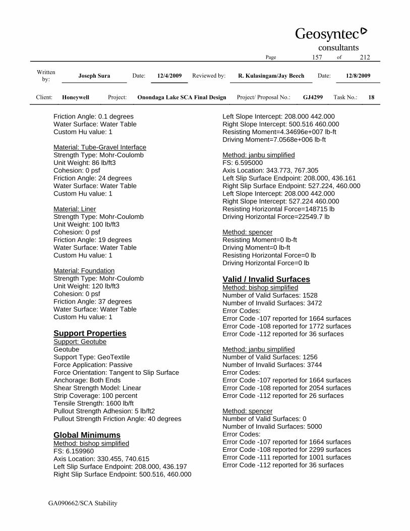
Page 157 of 212
Written by: Joseph Sura Date: 12/4/2009 Reviewed by: R. Kulasingam/Jay Beech Date: 12/8/2009
Client: Honeywell Project: Onondaga Lake SCA Final Design Project/ Proposal No.: GJ4299 Task No.: 18
GA090662/SCA Stability
Friction Angle: 0.1 degrees Water Surface: Water Table Custom Hu value: 1 Material: Tube-Gravel Interface Strength Type: Mohr-Coulomb Unit Weight: 86 lb/ft3 Cohesion: 0 psf Friction Angle: 24 degrees Water Surface: Water Table Custom Hu value: 1 Material: Liner Strength Type: Mohr-Coulomb Unit Weight: 100 lb/ft3 Cohesion: 0 psf Friction Angle: 19 degrees Water Surface: Water Table Custom Hu value: 1 Material: Foundation Strength Type: Mohr-Coulomb Unit Weight: 120 lb/ft3 Cohesion: 0 psf Friction Angle: 37 degrees Water Surface: Water Table Custom Hu value: 1 Support Properties Support: Geotube Geotube Support Type: GeoTextile Force Application: Passive Force Orientation: Tangent to Slip Surface Anchorage: Both Ends Shear Strength Model: Linear Strip Coverage: 100 percent Tensile Strength: 1600 lb/ft Pullout Strength Adhesion: 5 lb/ft2 Pullout Strength Friction Angle: 40 degrees Global Minimums Method: bishop simplified FS: 6.159960 Axis Location: 330.455, 740.615 Left Slip Surface Endpoint: 208.000, 436.197 Right Slip Surface Endpoint: 500.516, 460.000
Left Slope Intercept: 208.000 442.000 Right Slope Intercept: 500.516 460.000 Resisting Moment=4.34696e+007 lb-ft Driving Moment=7.0568e+006 lb-ft Method: janbu simplified FS: 6.595000 Axis Location: 343.773, 767.305 Left Slip Surface Endpoint: 208.000, 436.161 Right Slip Surface Endpoint: 527.224, 460.000 Left Slope Intercept: 208.000 442.000 Right Slope Intercept: 527.224 460.000 Resisting Horizontal Force=148715 lb Driving Horizontal Force=22549.7 lb Method: spencer Resisting Moment=0 lb-ft Driving Moment=0 lb-ft Resisting Horizontal Force=0 lb Driving Horizontal Force=0 lb Valid / Invalid Surfaces Method: bishop simplified Number of Valid Surfaces: 1528 Number of Invalid Surfaces: 3472 Error Codes: Error Code -107 reported for 1664 surfaces Error Code -108 reported for 1772 surfaces Error Code -112 reported for 36 surfaces Method: janbu simplified Number of Valid Surfaces: 1256 Number of Invalid Surfaces: 3744 Error Codes: Error Code -107 reported for 1664 surfaces Error Code -108 reported for 2054 surfaces Error Code -112 reported for 26 surfaces Method: spencer Number of Valid Surfaces: 0 Number of Invalid Surfaces: 5000 Error Codes: Error Code -107 reported for 1664 surfaces Error Code -108 reported for 2299 surfaces Error Code -111 reported for 1001 surfaces Error Code -112 reported for 36 surfaces

Page 158 of 212
Written by: Joseph Sura Date: 12/4/2009 Reviewed by: R. Kulasingam/Jay Beech Date: 12/8/2009
Client: Honeywell Project: Onondaga Lake SCA Final Design Project/ Proposal No.: GJ4299 Task No.: 18
GA090662/SCA Stability
List of All Coordinates Block Search Polyline 208.000 436.003 466.201 436.248 Material Boundary 0.000 427.500 122.000 424.650 122.359 424.645 177.171 423.910 204.000 423.550 267.961 422.659 405.000 420.750 472.000 422.050 768.000 422.250 805.000 423.150 925.000 423.250 1165.000 428.350 1347.000 425.150 1436.000 426.150 1642.000 424.450 1786.163 426.261 1841.000 426.950 1841.123 426.953 Material Boundary 122.000 424.500 122.359 424.645 Material Boundary 180.062 426.825 347.000 423.600 600.000 423.600 640.000 424.000 728.000 424.000 1102.000 431.000 1176.000 431.000 1356.000 428.000 1474.000 427.500 1619.000 426.500 1689.000 426.500 1785.758 427.937 Material Boundary 1827.000 432.300 1841.123 426.953
Material Boundary 188.000 430.000 824.000 430.000 1161.000 433.000 1236.000 432.000 1400.000 431.000 1778.100 431.000 Material Boundary 188.000 430.250 506.200 430.250 507.700 430.250 824.000 430.250 824.200 430.252 825.700 430.265 1142.148 433.082 1143.812 433.097 1161.000 433.250 1236.000 432.250 1400.000 431.250 1460.199 431.250 1461.784 431.250 1778.100 431.250 Material Boundary 208.000 436.000 506.200 436.000 507.700 436.000 824.000 436.000 824.200 436.002 825.700 436.015 1142.148 438.832 1143.812 438.847 1161.000 439.000 1236.000 438.000 1400.000 437.000 1460.199 437.000 1461.784 437.000 1758.000 437.000 Material Boundary 208.000 436.250 466.200 436.250 467.700 436.250 724.201 436.250 725.697 436.250 824.000 436.250 982.197 437.658

Page 159 of 212
Written by: Joseph Sura Date: 12/4/2009 Reviewed by: R. Kulasingam/Jay Beech Date: 12/8/2009
Client: Honeywell Project: Onondaga Lake SCA Final Design Project/ Proposal No.: GJ4299 Task No.: 18
GA090662/SCA Stability
983.718 437.672 1161.000 439.250 1236.000 438.250 1240.193 438.224 1241.724 438.215 1400.000 437.250 1498.182 437.250 1499.766 437.250 1758.000 437.250 Material Boundary 228.000 442.000 466.200 442.000 467.700 442.000 724.201 442.000 725.697 442.000 824.000 442.000 982.197 443.408 983.718 443.422 1161.000 445.000 1236.000 444.000 1240.193 443.974 1241.724 443.965 1400.000 443.000 1498.182 443.000 1499.766 443.000 1738.000 443.000 Material Boundary 228.000 442.250 530.200 442.250 531.700 442.250 824.000 442.250 832.191 442.323 833.715 442.336 1134.188 445.011 1135.719 445.025 1161.000 445.250 1236.000 444.250 1400.000 443.250 1436.205 443.250 1437.780 443.250 1738.000 443.250 Material Boundary 248.000 448.000 530.200 448.000 531.700 448.000
824.000 448.000 832.191 448.073 833.715 448.086 1134.188 450.761 1135.719 450.775 1161.000 451.000 1236.000 450.000 1400.000 449.000 1436.205 449.000 1437.780 449.000 1718.000 449.000 Material Boundary 248.000 448.250 493.200 448.250 494.700 448.250 738.195 448.250 739.701 448.250 824.000 448.250 983.182 449.667 984.724 449.681 1161.000 451.250 1228.192 450.354 1229.723 450.334 1236.000 450.250 1400.000 449.250 1473.204 449.250 1474.788 449.250 1718.000 449.250 Material Boundary 268.000 454.000 493.200 454.000 494.700 454.000 738.195 454.000 739.701 454.000 824.000 454.000 983.182 455.417 984.724 455.431 1161.000 457.000 1228.192 456.104 1229.723 456.084 1236.000 456.000 1400.000 455.000 1473.204 455.000 1474.788 455.000 1698.000 455.000

Page 160 of 212
Written by: Joseph Sura Date: 12/4/2009 Reviewed by: R. Kulasingam/Jay Beech Date: 12/8/2009
Client: Honeywell Project: Onondaga Lake SCA Final Design Project/ Proposal No.: GJ4299 Task No.: 18
GA090662/SCA Stability
Material Boundary 268.000 454.250 554.200 454.250 555.700 454.250 824.000 454.250 840.193 454.394 841.706 454.408 1126.178 456.940 1127.707 456.954 1161.000 457.250 1236.000 456.250 1400.000 455.250 1412.195 455.250 1413.743 455.250 1698.000 455.250 Material Boundary 506.200 430.250 506.200 436.000 Material Boundary 507.700 430.250 507.700 436.000 Material Boundary 466.200 436.250 466.200 442.000 Material Boundary 467.700 436.250 467.700 442.000 Material Boundary 530.200 442.250 530.200 448.000 Material Boundary 531.700 442.250 531.700 448.000 Material Boundary 493.200 448.250 493.200 454.000 Material Boundary 494.700 448.250 494.700 454.000
Material Boundary 554.200 454.250 554.200 460.000 Material Boundary 555.700 454.250 555.700 460.000 Material Boundary 824.200 430.252 824.200 436.002 Material Boundary 825.700 430.265 825.700 436.015 Material Boundary 724.201 436.250 724.201 442.000 Material Boundary 725.697 436.250 725.697 442.000 Material Boundary 738.195 448.250 738.195 454.000 Material Boundary 739.701 448.250 739.701 454.000 Material Boundary 840.193 454.394 840.193 460.144 Material Boundary 841.706 454.408 841.706 460.158 Material Boundary 832.191 442.323 832.191 448.073 Material Boundary 833.715 442.336 833.715 448.086
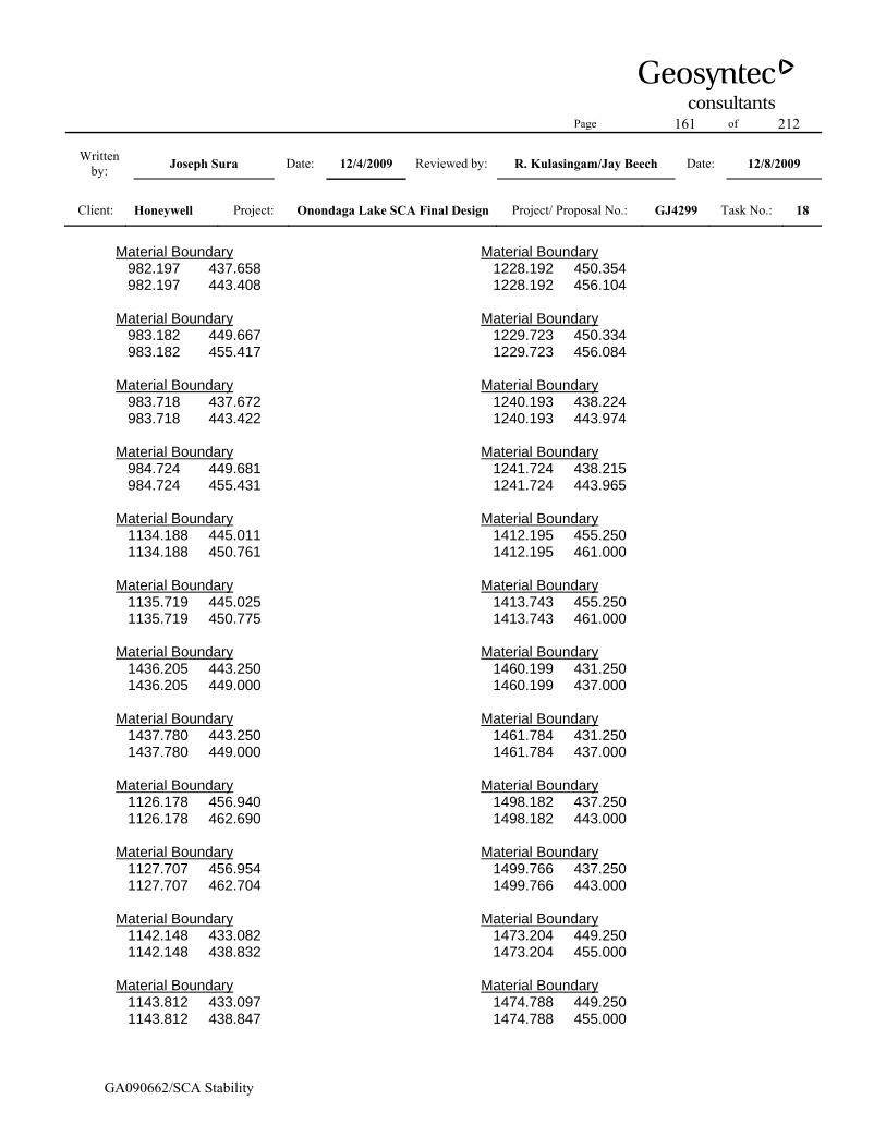
Page 161 of 212
Written by: Joseph Sura Date: 12/4/2009 Reviewed by: R. Kulasingam/Jay Beech Date: 12/8/2009
Client: Honeywell Project: Onondaga Lake SCA Final Design Project/ Proposal No.: GJ4299 Task No.: 18
GA090662/SCA Stability
Material Boundary 982.197 437.658 982.197 443.408 Material Boundary 983.182 449.667 983.182 455.417 Material Boundary 983.718 437.672 983.718 443.422 Material Boundary 984.724 449.681 984.724 455.431 Material Boundary 1134.188 445.011 1134.188 450.761 Material Boundary 1135.719 445.025 1135.719 450.775 Material Boundary 1436.205 443.250 1436.205 449.000 Material Boundary 1437.780 443.250 1437.780 449.000 Material Boundary 1126.178 456.940 1126.178 462.690 Material Boundary 1127.707 456.954 1127.707 462.704 Material Boundary 1142.148 433.082 1142.148 438.832 Material Boundary 1143.812 433.097 1143.812 438.847
Material Boundary 1228.192 450.354 1228.192 456.104 Material Boundary 1229.723 450.334 1229.723 456.084 Material Boundary 1240.193 438.224 1240.193 443.974 Material Boundary 1241.724 438.215 1241.724 443.965 Material Boundary 1412.195 455.250 1412.195 461.000 Material Boundary 1413.743 455.250 1413.743 461.000 Material Boundary 1460.199 431.250 1460.199 437.000 Material Boundary 1461.784 431.250 1461.784 437.000 Material Boundary 1498.182 437.250 1498.182 443.000 Material Boundary 1499.766 437.250 1499.766 443.000 Material Boundary 1473.204 449.250 1473.204 455.000 Material Boundary 1474.788 449.250 1474.788 455.000

Page 162 of 212
Written by: Joseph Sura Date: 12/4/2009 Reviewed by: R. Kulasingam/Jay Beech Date: 12/8/2009
Client: Honeywell Project: Onondaga Lake SCA Final Design Project/ Proposal No.: GJ4299 Task No.: 18
GA090662/SCA Stability
Material Boundary 165.176 430.000 177.171 423.910 Material Boundary 0.000 387.500 268.000 387.845 1979.000 390.050 Material Boundary 1786.163 426.261 1799.372 431.000 Material Boundary 164.400 430.400 165.176 430.000 Material Boundary 1799.372 431.000 1803.000 432.300 Material Boundary 164.400 430.400 165.257 430.401 Material Boundary 267.961 422.659 268.000 387.845 Material Boundary 157.414 434.000 162.619 431.318 164.400 430.400 External Boundary 107.318 424.996 0.000 427.500 0.000 387.500 0.000 347.500 1979.000 350.000 1979.000 390.050 1979.000 430.050 1841.123 426.953 1841.000 427.000 1827.000 432.300 1803.000 432.300 1801.461 432.301 1798.000 431.000
1792.668 429.000 1790.000 428.000 1785.758 427.937 1785.600 428.000 1783.100 429.000 1780.600 430.000 1778.100 431.000 1778.100 431.250 1778.100 437.000 1758.000 437.000 1758.000 437.250 1758.000 443.000 1738.000 443.000 1738.000 443.250 1738.000 449.000 1718.000 449.000 1718.000 449.250 1718.000 455.000 1698.000 455.000 1698.000 455.250 1698.000 461.000 1413.743 461.000 1412.195 461.000 1400.000 461.000 1236.000 462.000 1161.000 463.000 1127.707 462.704 1126.178 462.690 841.706 460.158 840.193 460.144 824.000 460.000 555.700 460.000 554.200 460.000 268.000 460.000 268.000 454.250 268.000 454.000 248.000 454.000 248.000 448.250 248.000 448.000 228.000 448.000 228.000 442.250 228.000 442.000 208.000 442.000 208.000 436.250 208.000 436.000 188.000 436.000 188.000 430.250 188.000 430.000
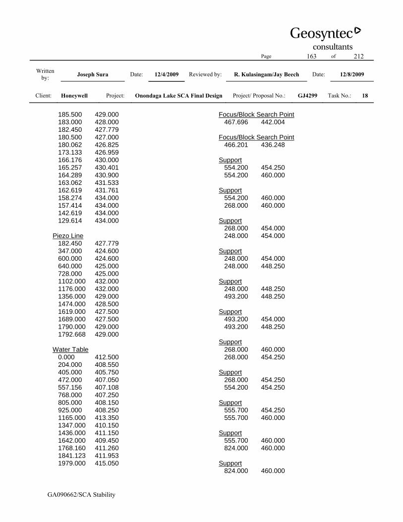
Page 163 of 212
Written by: Joseph Sura Date: 12/4/2009 Reviewed by: R. Kulasingam/Jay Beech Date: 12/8/2009
Client: Honeywell Project: Onondaga Lake SCA Final Design Project/ Proposal No.: GJ4299 Task No.: 18
GA090662/SCA Stability
185.500 429.000 183.000 428.000 182.450 427.779 180.500 427.000 180.062 426.825 173.133 426.959 166.176 430.000 165.257 430.401 164.289 430.900 163.062 431.533 162.619 431.761 158.274 434.000 157.414 434.000 142.619 434.000 129.614 434.000 Piezo Line 182.450 427.779 347.000 424.600 600.000 424.600 640.000 425.000 728.000 425.000 1102.000 432.000 1176.000 432.000 1356.000 429.000 1474.000 428.500 1619.000 427.500 1689.000 427.500 1790.000 429.000 1792.668 429.000 Water Table 0.000 412.500 204.000 408.550 405.000 405.750 472.000 407.050 557.156 407.108 768.000 407.250 805.000 408.150 925.000 408.250 1165.000 413.350 1347.000 410.150 1436.000 411.150 1642.000 409.450 1768.160 411.260 1841.123 411.953 1979.000 415.050
Focus/Block Search Point 467.696 442.004 Focus/Block Search Point 466.201 436.248 Support 554.200 454.250 554.200 460.000 Support 554.200 460.000 268.000 460.000 Support 268.000 454.000 248.000 454.000 Support 248.000 454.000 248.000 448.250 Support 248.000 448.250 493.200 448.250 Support 493.200 454.000 493.200 448.250 Support 268.000 460.000 268.000 454.250 Support 268.000 454.250 554.200 454.250 Support 555.700 454.250 555.700 460.000 Support 555.700 460.000 824.000 460.000 Support 824.000 460.000

Page 164 of 212
Written by: Joseph Sura Date: 12/4/2009 Reviewed by: R. Kulasingam/Jay Beech Date: 12/8/2009
Client: Honeywell Project: Onondaga Lake SCA Final Design Project/ Proposal No.: GJ4299 Task No.: 18
GA090662/SCA Stability
840.193 460.144 Support 840.193 460.144 840.193 454.394 Support 840.193 454.394 824.000 454.250 Support 824.000 454.250 555.700 454.250 Support 738.195 454.000 738.195 448.250 Support 739.701 454.000 739.701 448.250 Support 738.195 454.000 494.700 454.000 Support 494.700 454.000 494.700 448.250 Support 494.700 448.250 738.195 448.250 Support 724.201 442.000 724.201 436.250 Support 724.201 436.250 467.700 436.250 Support 467.700 436.250 467.700 442.000 Support 467.700 442.000
724.201 442.000 Support 228.000 448.000 228.000 442.250 Support 248.000 448.000 530.200 448.000 Support 530.200 448.000 530.200 442.250 Support 531.700 442.250 531.700 448.000 Support 530.200 442.250 228.000 442.250 Support 228.000 448.000 248.000 448.000 Support 208.000 436.250 208.000 442.000 Support 208.000 442.000 228.000 442.000 Support 228.000 442.000 466.200 442.000 Support 466.200 442.000 466.200 436.250 Support 466.200 436.250 208.000 436.250 Support 188.000 430.250

Page 165 of 212
Written by: Joseph Sura Date: 12/4/2009 Reviewed by: R. Kulasingam/Jay Beech Date: 12/8/2009
Client: Honeywell Project: Onondaga Lake SCA Final Design Project/ Proposal No.: GJ4299 Task No.: 18
GA090662/SCA Stability
188.000 436.000 Support 188.000 436.000 208.000 436.000 Support 208.000 436.000 506.200 436.000 Support 507.700 436.000 507.700 430.250 Support 506.200 436.000 506.200 430.250 Support 506.200 430.250 188.000 430.250 Support 507.700 430.250 824.200 430.252 Support 824.200 430.252 824.200 436.002 Support 824.200 436.002 507.700 436.000 Support 832.191 442.323 832.191 448.073 Support 833.715 442.336 833.715 448.086 Support 832.191 448.073 824.000 448.000 Support 824.000 448.000
531.700 448.000 Support 531.700 442.250 824.000 442.250 Support 824.000 442.250 832.191 442.323 Support 841.706 460.158 841.706 454.408 Support 825.700 436.015 825.700 430.265 Support 725.697 442.000 725.697 436.250 Support 725.697 436.250 824.000 436.250 Support 824.000 436.250 982.197 437.658 Support 982.197 437.658 982.197 443.408 Support 982.197 443.408 824.000 442.000 Support 824.000 442.000 725.697 442.000 Support 739.701 448.250 824.000 448.250 Support 824.000 448.250

Page 166 of 212
Written by: Joseph Sura Date: 12/4/2009 Reviewed by: R. Kulasingam/Jay Beech Date: 12/8/2009
Client: Honeywell Project: Onondaga Lake SCA Final Design Project/ Proposal No.: GJ4299 Task No.: 18
GA090662/SCA Stability
983.182 449.667 Support 983.182 449.667 983.182 455.417 Support 983.182 455.417 824.000 454.000 Support 824.000 454.000 739.701 454.000 Support 841.706 454.408 1126.178 456.940 Support 1126.178 456.940 1126.178 462.690 Support 1126.178 462.690 841.706 460.158 Support 833.715 448.086 1134.188 450.761 Support 1134.188 450.761 1134.188 445.011 Support 1134.188 445.011 833.715 442.336 Support 825.700 436.015 1142.148 438.832 Support 1142.148 438.832 1142.148 433.082 Support 1142.148 433.082
825.700 430.265 Support 984.724 455.431 984.724 449.681 Support 983.718 443.422 983.718 437.672 Support 983.718 437.672 1161.000 439.250 Support 1161.000 439.250 1236.000 438.250 Support 1236.000 438.250 1240.193 438.224 Support 1240.193 438.224 1240.193 443.974 Support 1240.193 443.974 1236.000 444.000 Support 1236.000 444.000 1161.000 445.000 Support 1161.000 445.000 983.718 443.422 Support 984.724 455.431 1161.000 457.000 Support 1161.000 457.000 1228.192 456.104 Support 1228.192 456.104

Page 167 of 212
Written by: Joseph Sura Date: 12/4/2009 Reviewed by: R. Kulasingam/Jay Beech Date: 12/8/2009
Client: Honeywell Project: Onondaga Lake SCA Final Design Project/ Proposal No.: GJ4299 Task No.: 18
GA090662/SCA Stability
1228.192 450.354 Support 1228.192 450.354 1161.000 451.250 Support 1161.000 451.250 984.724 449.681 Support 268.000 454.000 493.200 454.000 Support 1127.707 462.704 1127.707 456.954 Support 1127.707 462.704 1161.000 463.000 Support 1161.000 463.000 1236.000 462.000 Support 1236.000 462.000 1400.000 461.000 Support 1400.000 461.000 1412.195 461.000 Support 1412.195 461.000 1412.195 455.250 Support 1412.195 455.250 1400.000 455.250 Support 1400.000 455.250 1236.000 456.250 Support 1236.000 456.250
1161.000 457.250 Support 1161.000 457.250 1127.707 456.954 Support 1135.719 450.775 1135.719 445.025 Support 1135.719 450.775 1161.000 451.000 Support 1161.000 445.250 1135.719 445.025 Support 1161.000 445.250 1236.000 444.250 Support 1236.000 444.250 1400.000 443.250 Support 1400.000 443.250 1436.205 443.250 Support 1436.205 443.250 1436.205 449.000 Support 1437.780 449.000 1437.780 443.250 Support 1436.205 449.000 1400.000 449.000 Support 1400.000 449.000 1236.000 450.000 Support 1236.000 450.000

Page 168 of 212
Written by: Joseph Sura Date: 12/4/2009 Reviewed by: R. Kulasingam/Jay Beech Date: 12/8/2009
Client: Honeywell Project: Onondaga Lake SCA Final Design Project/ Proposal No.: GJ4299 Task No.: 18
GA090662/SCA Stability
1161.000 451.000 Support 1229.723 456.084 1229.723 450.334 Support 1229.723 450.334 1236.000 450.250 Support 1236.000 456.000 1229.723 456.084 Support 1236.000 456.000 1400.000 455.000 Support 1400.000 455.000 1473.204 455.000 Support 1473.204 455.000 1473.204 449.250 Support 1474.788 449.250 1474.788 455.000 Support 1473.204 449.250 1400.000 449.250 Support 1400.000 449.250 1236.000 450.250 Support 1241.724 438.215 1241.724 443.965 Support 1143.812 438.847 1143.812 433.097 Support 1143.812 433.097
1161.000 433.250 Support 1161.000 439.000 1143.812 438.847 Support 1161.000 439.000 1236.000 438.000 Support 1236.000 438.000 1400.000 437.000 Support 1400.000 437.000 1460.199 437.000 Support 1460.199 437.000 1460.199 431.250 Support 1461.784 431.250 1461.784 437.000 Support 1460.199 431.250 1400.000 431.250 Support 1400.000 431.250 1236.000 432.250 Support 1236.000 432.250 1161.000 433.250 Support 1241.724 438.215 1400.000 437.250 Support 1400.000 437.250 1498.182 437.250 Support 1498.182 443.000

Page 169 of 212
Written by: Joseph Sura Date: 12/4/2009 Reviewed by: R. Kulasingam/Jay Beech Date: 12/8/2009
Client: Honeywell Project: Onondaga Lake SCA Final Design Project/ Proposal No.: GJ4299 Task No.: 18
GA090662/SCA Stability
1498.182 437.250 Support 1499.766 437.250 1499.766 443.000 Support 1498.182 443.000 1400.000 443.000 Support 1400.000 443.000 1241.724 443.965 Support 1413.743 461.000 1413.743 455.250 Support 1413.743 461.000 1698.000 461.000 Support 1698.000 461.000 1698.000 455.250 Support 1698.000 455.250 1413.743 455.250 Support 1474.788 449.250 1718.000 449.250 Support 1718.000 449.250 1718.000 455.000 Support 1698.000 455.000 1474.788 455.000 Support 1461.784 431.250 1778.100 431.250 Support 1778.100 431.250
1778.100 437.000 Support 1758.000 437.000 1461.784 437.000 Support 1437.780 443.250 1738.000 443.250 Support 1738.000 443.250 1738.000 449.000 Support 1718.000 449.000 1437.780 449.000 Support 1499.766 437.250 1758.000 437.250 Support 1758.000 437.250 1758.000 443.000 Support 1738.000 443.000 1499.766 443.000 Support 1718.000 455.000 1698.000 455.000 Support 1718.000 449.000 1738.000 449.000 Support 1738.000 443.000 1758.000 443.000 Support 1758.000 437.000 1778.100 437.000

Page 170 of 212
Written by: Joseph Sura Date: 12/4/2009 Reviewed by: R. Kulasingam/Jay Beech Date: 12/8/2009
Client: Honeywell Project: Onondaga Lake SCA Final Design Project/ Proposal No.: GJ4299 Task No.: 18
GA090662/SCA Stability
Slide Analysis Information Document Name File Name: eastwest_nocover_tube_05_lab Project Settings Project Title: SLIDE - An Interactive Slope Stability Program Failure Direction: Right to Left Units of Measurement: Imperial Units Pore Fluid Unit Weight: 62.4 lb/ft3 Groundwater Method: Water Surfaces Data Output: Standard Calculate Excess Pore Pressure: Off Allow Ru with Water Surfaces or Grids: Off Random Numbers: Pseudo-random Seed Random Number Seed: 10116 Random Number Generation Method: Park and Miller v.3 Analysis Methods Analysis Methods used: Bishop simplified Janbu simplified Spencer Number of slices: 25 Tolerance: 0.005 Maximum number of iterations: 50 Surface Options Surface Type: Non-Circular Block Search Number of Surfaces: 5000 Pseudo-Random Surfaces: Enabled Convex Surfaces Only: Disabled Left Projection Angle (Start Angle): 95 Left Projection Angle (End Angle): 175 Right Projection Angle (Start Angle): 5 Right Projection Angle (End Angle): 85 Minimum Elevation: Not Defined Minimum Depth: Not Defined Material Properties Material: Final Cover Soil Strength Type: Mohr-Coulomb
Unit Weight: 120 lb/ft3 Cohesion: 0 psf Friction Angle: 30 degrees Water Surface: Water Table Custom Hu value: 1 Material: Dike Soil Strength Type: Mohr-Coulomb Unit Weight: 120 lb/ft3 Cohesion: 0 psf Friction Angle: 35 degrees Water Surface: Water Table Custom Hu value: 1 Material: Gravel Strength Type: Mohr-Coulomb Unit Weight: 120 lb/ft3 Cohesion: 0 psf Friction Angle: 38 degrees Water Surface: Piezometric Line 1 Custom Hu value: 1 Material: SOLW (undrained) Strength Type: Discrete function Unit Weight: 82 lb/ft3 Water Surface: Water Table Custom Hu value: 1 Material: Dredge Material Strength Type: Mohr-Coulomb Unit Weight: 86 lb/ft3 Cohesion: 0 psf Friction Angle: 15 degrees Water Surface: Water Table Custom Hu value: 1 Material: Tube-Tube Interface (Horizontal) Strength Type: Mohr-Coulomb Unit Weight: 86 lb/ft3 Cohesion: 0 psf Friction Angle: 15 degrees Water Surface: Water Table Custom Hu value: 1 Material: Tub-Tube Interface (Vertical) Strength Type: Mohr-Coulomb Unit Weight: 43 lb/ft3 Cohesion: 0 psf

Page 171 of 212
Written by: Joseph Sura Date: 12/4/2009 Reviewed by: R. Kulasingam/Jay Beech Date: 12/8/2009
Client: Honeywell Project: Onondaga Lake SCA Final Design Project/ Proposal No.: GJ4299 Task No.: 18
GA090662/SCA Stability
Friction Angle: 0.1 degrees Water Surface: Water Table Custom Hu value: 1 Material: Tube-Gravel Interface Strength Type: Mohr-Coulomb Unit Weight: 86 lb/ft3 Cohesion: 0 psf Friction Angle: 24 degrees Water Surface: Water Table Custom Hu value: 1 Material: Liner Strength Type: Mohr-Coulomb Unit Weight: 100 lb/ft3 Cohesion: 0 psf Friction Angle: 19 degrees Water Surface: Water Table Custom Hu value: 1 Material: Foundation Strength Type: Mohr-Coulomb Unit Weight: 120 lb/ft3 Cohesion: 0 psf Friction Angle: 37 degrees Water Surface: Water Table Custom Hu value: 1 Support Properties Support: Geotube Geotube Support Type: GeoTextile Force Application: Passive Force Orientation: Tangent to Slip Surface Anchorage: Both Ends Shear Strength Model: Linear Strip Coverage: 100 percent Tensile Strength: 1600 lb/ft Pullout Strength Adhesion: 5 lb/ft2 Pullout Strength Friction Angle: 40 degrees Global Minimums Method: bishop simplified FS: 9.403780 Axis Location: 339.979, 808.592 Left Slip Surface Endpoint: 188.000, 430.244 Right Slip Surface Endpoint: 551.470, 460.000
Left Slope Intercept: 188.000 436.000 Right Slope Intercept: 551.470 460.000 Resisting Moment=1.30382e+008 lb-ft Driving Moment=1.38649e+007 lb-ft Method: janbu simplified FS: 9.809610 Axis Location: 357.745, 844.189 Left Slip Surface Endpoint: 188.000, 430.200 Right Slip Surface Endpoint: 587.089, 460.000 Left Slope Intercept: 188.000 436.000 Right Slope Intercept: 587.089 460.000 Resisting Horizontal Force=353073 lb Driving Horizontal Force=35992.6 lb Method: spencer Resisting Moment=0 lb-ft Driving Moment=0 lb-ft Resisting Horizontal Force=0 lb Driving Horizontal Force=0 lb Valid / Invalid Surfaces Method: bishop simplified Number of Valid Surfaces: 1648 Number of Invalid Surfaces: 3352 Error Codes: Error Code -107 reported for 1640 surfaces Error Code -108 reported for 1654 surfaces Error Code -112 reported for 58 surfaces Method: janbu simplified Number of Valid Surfaces: 1420 Number of Invalid Surfaces: 3580 Error Codes: Error Code -107 reported for 1640 surfaces Error Code -108 reported for 1906 surfaces Error Code -112 reported for 34 surfaces Method: spencer Number of Valid Surfaces: 0 Number of Invalid Surfaces: 5000 Error Codes: Error Code -107 reported for 1640 surfaces Error Code -108 reported for 2152 surfaces Error Code -111 reported for 1149 surfaces Error Code -112 reported for 59 surfaces

Page 172 of 212
Written by: Joseph Sura Date: 12/4/2009 Reviewed by: R. Kulasingam/Jay Beech Date: 12/8/2009
Client: Honeywell Project: Onondaga Lake SCA Final Design Project/ Proposal No.: GJ4299 Task No.: 18
GA090662/SCA Stability
Slide Analysis Information Document Name File Name: eastwest_nocover_liner_lab Project Settings Project Title: SLIDE - An Interactive Slope Stability Program Failure Direction: Right to Left Units of Measurement: Imperial Units Pore Fluid Unit Weight: 62.4 lb/ft3 Groundwater Method: Water Surfaces Data Output: Standard Calculate Excess Pore Pressure: Off Allow Ru with Water Surfaces or Grids: Off Random Numbers: Pseudo-random Seed Random Number Seed: 10116 Random Number Generation Method: Park and Miller v.3 Analysis Methods Analysis Methods used: Bishop simplified Janbu simplified Spencer Number of slices: 25 Tolerance: 0.005 Maximum number of iterations: 50 Surface Options Surface Type: Non-Circular Block Search Number of Surfaces: 5000 Pseudo-Random Surfaces: Enabled Convex Surfaces Only: Disabled Left Projection Angle (Start Angle): 95 Left Projection Angle (End Angle): 175 Right Projection Angle (Start Angle): 5 Right Projection Angle (End Angle): 85 Minimum Elevation: Not Defined Minimum Depth: Not Defined Material Properties Material: Final Cover Soil Strength Type: Mohr-Coulomb
Unit Weight: 120 lb/ft3 Cohesion: 0 psf Friction Angle: 30 degrees Water Surface: Water Table Custom Hu value: 1 Material: Dike Soil Strength Type: Mohr-Coulomb Unit Weight: 120 lb/ft3 Cohesion: 0 psf Friction Angle: 35 degrees Water Surface: Water Table Custom Hu value: 1 Material: Gravel Strength Type: Mohr-Coulomb Unit Weight: 120 lb/ft3 Cohesion: 0 psf Friction Angle: 38 degrees Water Surface: Piezometric Line 1 Custom Hu value: 1 Material: SOLW (undrained) Strength Type: Discrete function Unit Weight: 82 lb/ft3 Water Surface: Water Table Custom Hu value: 1 Material: Dredge Material Strength Type: Mohr-Coulomb Unit Weight: 86 lb/ft3 Cohesion: 0 psf Friction Angle: 15 degrees Water Surface: Water Table Custom Hu value: 1 Material: Tube-Tube Interface (Horizontal) Strength Type: Mohr-Coulomb Unit Weight: 86 lb/ft3 Cohesion: 0 psf Friction Angle: 15 degrees Water Surface: Water Table Custom Hu value: 1 Material: Tub-Tube Interface (Vertical) Strength Type: Mohr-Coulomb Unit Weight: 43 lb/ft3 Cohesion: 0 psf

Page 173 of 212
Written by: Joseph Sura Date: 12/4/2009 Reviewed by: R. Kulasingam/Jay Beech Date: 12/8/2009
Client: Honeywell Project: Onondaga Lake SCA Final Design Project/ Proposal No.: GJ4299 Task No.: 18
GA090662/SCA Stability
Friction Angle: 0.1 degrees Water Surface: Water Table Custom Hu value: 1 Material: Tube-Gravel Interface Strength Type: Mohr-Coulomb Unit Weight: 86 lb/ft3 Cohesion: 0 psf Friction Angle: 24 degrees Water Surface: Water Table Custom Hu value: 1 Material: Liner Strength Type: Mohr-Coulomb Unit Weight: 100 lb/ft3 Cohesion: 0 psf Friction Angle: 19 degrees Water Surface: Water Table Custom Hu value: 1 Material: Foundation Strength Type: Mohr-Coulomb Unit Weight: 120 lb/ft3 Cohesion: 0 psf Friction Angle: 37 degrees Water Surface: Water Table Custom Hu value: 1 Support Properties Support: Geotube Geotube Support Type: GeoTextile Force Application: Passive Force Orientation: Tangent to Slip Surface Anchorage: Both Ends Shear Strength Model: Linear Strip Coverage: 100 percent Tensile Strength: 1600 lb/ft Pullout Strength Adhesion: 5 lb/ft2 Pullout Strength Friction Angle: 40 degrees Global Minimums Method: bishop simplified FS: 1.808920 Axis Location: 200.120, 584.614 Left Slip Surface Endpoint: 159.018, 431.727 Right Slip Surface Endpoint: 297.768, 460.000
Resisting Moment=7.93133e+006 lb-ft Driving Moment=4.38456e+006 lb-ft Method: janbu simplified FS: 1.863770 Axis Location: 200.120, 584.614 Left Slip Surface Endpoint: 159.018, 431.727 Right Slip Surface Endpoint: 297.768, 460.000 Resisting Horizontal Force=48680.7 lb Driving Horizontal Force=26119.5 lb Method: spencer FS: 1.909240 Axis Location: 214.140, 607.141 Left Slip Surface Endpoint: 162.955, 430.152 Right Slip Surface Endpoint: 325.020, 460.000 Resisting Moment=1.42301e+007 lb-ft Driving Moment=7.4533e+006 lb-ft Resisting Horizontal Force=75987 lb Driving Horizontal Force=39799.6 lb Valid / Invalid Surfaces Method: bishop simplified Number of Valid Surfaces: 798 Number of Invalid Surfaces: 4202 Error Codes: Error Code -105 reported for 3904 surfaces Error Code -107 reported for 27 surfaces Error Code -108 reported for 128 surfaces Error Code -112 reported for 143 surfaces Method: janbu simplified Number of Valid Surfaces: 762 Number of Invalid Surfaces: 4238 Error Codes: Error Code -105 reported for 3904 surfaces Error Code -107 reported for 27 surfaces Error Code -108 reported for 172 surfaces Error Code -112 reported for 135 surfaces Method: spencer Number of Valid Surfaces: 246 Number of Invalid Surfaces: 4754 Error Codes: Error Code -105 reported for 3904 surfaces Error Code -107 reported for 27 surfaces Error Code -108 reported for 171 surfaces

Page 174 of 212
Written by: Joseph Sura Date: 12/4/2009 Reviewed by: R. Kulasingam/Jay Beech Date: 12/8/2009
Client: Honeywell Project: Onondaga Lake SCA Final Design Project/ Proposal No.: GJ4299 Task No.: 18
GA090662/SCA Stability
Error Code -111 reported for 508 surfaces Error Code -112 reported for 144 surfaces

Page 175 of 212
Written by: Joseph Sura Date: 12/4/2009 Reviewed by: R. Kulasingam/Jay Beech Date: 12/8/2009
Client: Honeywell Project: Onondaga Lake SCA Final Design Project/ Proposal No.: GJ4299 Task No.: 18
GA090662/SCA Stability
Slide Analysis Information Document Name File Name: eastwest_nocover_global_su_lab Project Settings Project Title: SLIDE - An Interactive Slope Stability Program Failure Direction: Right to Left Units of Measurement: Imperial Units Pore Fluid Unit Weight: 62.4 lb/ft3 Groundwater Method: Water Surfaces Data Output: Standard Calculate Excess Pore Pressure: Off Allow Ru with Water Surfaces or Grids: Off Random Numbers: Pseudo-random Seed Random Number Seed: 10116 Random Number Generation Method: Park and Miller v.3 Analysis Methods Analysis Methods used: Bishop simplified Janbu simplified Spencer Number of slices: 25 Tolerance: 0.005 Maximum number of iterations: 50 Surface Options Surface Type: Circular Search Method: Grid Search Radius increment: 10 Composite Surfaces: Disabled Reverse Curvature: Create Tension Crack Minimum Elevation: Not Defined Minimum Depth: Not Defined Material Properties Material: Final Cover Soil Strength Type: Mohr-Coulomb Unit Weight: 120 lb/ft3 Cohesion: 0 psf Friction Angle: 30 degrees
Water Surface: Water Table Custom Hu value: 1 Material: Dike Soil Strength Type: Mohr-Coulomb Unit Weight: 120 lb/ft3 Cohesion: 0 psf Friction Angle: 35 degrees Water Surface: Water Table Custom Hu value: 1 Material: Gravel Strength Type: Mohr-Coulomb Unit Weight: 120 lb/ft3 Cohesion: 0 psf Friction Angle: 38 degrees Water Surface: Piezometric Line 1 Custom Hu value: 1 Material: SOLW (undrained) Strength Type: Discrete function Unit Weight: 82 lb/ft3 Water Surface: Water Table Custom Hu value: 1 Material: Dredge Material Strength Type: Mohr-Coulomb Unit Weight: 86 lb/ft3 Cohesion: 0 psf Friction Angle: 15 degrees Water Surface: Water Table Custom Hu value: 1 Material: Tube-Tube Interface (Horizontal) Strength Type: Mohr-Coulomb Unit Weight: 86 lb/ft3 Cohesion: 0 psf Friction Angle: 15 degrees Water Surface: Water Table Custom Hu value: 1 Material: Tub-Tube Interface (Vertical) Strength Type: Mohr-Coulomb Unit Weight: 43 lb/ft3 Cohesion: 0 psf Friction Angle: 0.1 degrees Water Surface: Water Table Custom Hu value: 1

Page 176 of 212
Written by: Joseph Sura Date: 12/4/2009 Reviewed by: R. Kulasingam/Jay Beech Date: 12/8/2009
Client: Honeywell Project: Onondaga Lake SCA Final Design Project/ Proposal No.: GJ4299 Task No.: 18
GA090662/SCA Stability
Material: Tube-Gravel Interface Strength Type: Mohr-Coulomb Unit Weight: 86 lb/ft3 Cohesion: 0 psf Friction Angle: 24 degrees Water Surface: Water Table Custom Hu value: 1 Material: Liner Strength Type: Mohr-Coulomb Unit Weight: 100 lb/ft3 Cohesion: 0 psf Friction Angle: 19 degrees Water Surface: Water Table Custom Hu value: 1 Material: Foundation Strength Type: Mohr-Coulomb Unit Weight: 120 lb/ft3 Cohesion: 0 psf Friction Angle: 37 degrees Water Surface: Water Table Custom Hu value: 1 Support Properties Support: Geotube Geotube Support Type: GeoTextile Force Application: Passive Force Orientation: Tangent to Slip Surface Anchorage: Both Ends Shear Strength Model: Linear Strip Coverage: 100 percent Tensile Strength: 1600 lb/ft Pullout Strength Adhesion: 5 lb/ft2 Pullout Strength Friction Angle: 40 degrees Global Minimums Method: bishop simplified FS: 1.360620 Center: 229.669, 488.062 Radius: 84.414 Left Slip Surface Endpoint: 171.784, 426.621 Right Slip Surface Endpoint: 309.282, 460.000 Resisting Moment=8.19054e+006 lb-ft Driving Moment=6.01973e+006 lb-ft
Method: janbu simplified FS: 1.339970 Center: 229.669, 488.062 Radius: 84.414 Left Slip Surface Endpoint: 171.784, 426.621 Right Slip Surface Endpoint: 309.282, 460.000 Resisting Horizontal Force=77760.4 lb Driving Horizontal Force=58031.5 lb Method: spencer FS: 1.359710 Center: 229.669, 488.062 Radius: 84.414 Left Slip Surface Endpoint: 171.784, 426.621 Right Slip Surface Endpoint: 309.282, 460.000 Resisting Moment=8.18509e+006 lb-ft Driving Moment=6.01973e+006 lb-ft Resisting Horizontal Force=77704.5 lb Driving Horizontal Force=57147.8 lb Valid / Invalid Surfaces Method: bishop simplified Number of Valid Surfaces: 9250 Number of Invalid Surfaces: 9241 Error Codes: Error Code -103 reported for 7193 surfaces Error Code -105 reported for 1 surface Error Code -106 reported for 551 surfaces Error Code -107 reported for 239 surfaces Error Code -108 reported for 136 surfaces Error Code -110 reported for 79 surfaces Error Code -112 reported for 1042 surfaces Method: janbu simplified Number of Valid Surfaces: 8601 Number of Invalid Surfaces: 9890 Error Codes: Error Code -103 reported for 7193 surfaces Error Code -105 reported for 1 surface Error Code -106 reported for 551 surfaces Error Code -107 reported for 239 surfaces Error Code -108 reported for 743 surfaces Error Code -110 reported for 79 surfaces Error Code -112 reported for 1084 surfaces Method: spencer

Page 177 of 212
Written by: Joseph Sura Date: 12/4/2009 Reviewed by: R. Kulasingam/Jay Beech Date: 12/8/2009
Client: Honeywell Project: Onondaga Lake SCA Final Design Project/ Proposal No.: GJ4299 Task No.: 18
GA090662/SCA Stability
Number of Valid Surfaces: 5324 Number of Invalid Surfaces: 13167 Error Codes: Error Code -103 reported for 7193 surfaces Error Code -105 reported for 1 surface Error Code -106 reported for 551 surfaces Error Code -107 reported for 239 surfaces Error Code -108 reported for 876 surfaces Error Code -110 reported for 79 surfaces Error Code -111 reported for 3126 surfaces Error Code -112 reported for 1102 surfaces
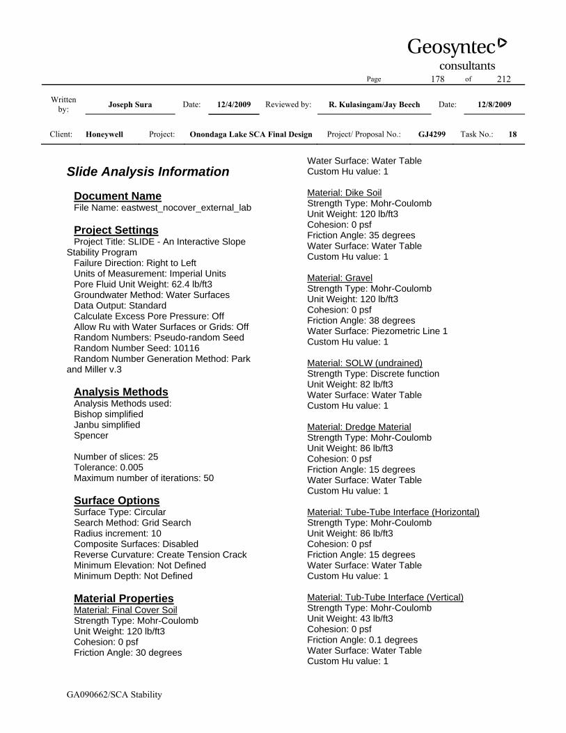
Page 178 of 212
Written by: Joseph Sura Date: 12/4/2009 Reviewed by: R. Kulasingam/Jay Beech Date: 12/8/2009
Client: Honeywell Project: Onondaga Lake SCA Final Design Project/ Proposal No.: GJ4299 Task No.: 18
GA090662/SCA Stability
Slide Analysis Information Document Name File Name: eastwest_nocover_external_lab Project Settings Project Title: SLIDE - An Interactive Slope Stability Program Failure Direction: Right to Left Units of Measurement: Imperial Units Pore Fluid Unit Weight: 62.4 lb/ft3 Groundwater Method: Water Surfaces Data Output: Standard Calculate Excess Pore Pressure: Off Allow Ru with Water Surfaces or Grids: Off Random Numbers: Pseudo-random Seed Random Number Seed: 10116 Random Number Generation Method: Park and Miller v.3 Analysis Methods Analysis Methods used: Bishop simplified Janbu simplified Spencer Number of slices: 25 Tolerance: 0.005 Maximum number of iterations: 50 Surface Options Surface Type: Circular Search Method: Grid Search Radius increment: 10 Composite Surfaces: Disabled Reverse Curvature: Create Tension Crack Minimum Elevation: Not Defined Minimum Depth: Not Defined Material Properties Material: Final Cover Soil Strength Type: Mohr-Coulomb Unit Weight: 120 lb/ft3 Cohesion: 0 psf Friction Angle: 30 degrees
Water Surface: Water Table Custom Hu value: 1 Material: Dike Soil Strength Type: Mohr-Coulomb Unit Weight: 120 lb/ft3 Cohesion: 0 psf Friction Angle: 35 degrees Water Surface: Water Table Custom Hu value: 1 Material: Gravel Strength Type: Mohr-Coulomb Unit Weight: 120 lb/ft3 Cohesion: 0 psf Friction Angle: 38 degrees Water Surface: Piezometric Line 1 Custom Hu value: 1 Material: SOLW (undrained) Strength Type: Discrete function Unit Weight: 82 lb/ft3 Water Surface: Water Table Custom Hu value: 1 Material: Dredge Material Strength Type: Mohr-Coulomb Unit Weight: 86 lb/ft3 Cohesion: 0 psf Friction Angle: 15 degrees Water Surface: Water Table Custom Hu value: 1 Material: Tube-Tube Interface (Horizontal) Strength Type: Mohr-Coulomb Unit Weight: 86 lb/ft3 Cohesion: 0 psf Friction Angle: 15 degrees Water Surface: Water Table Custom Hu value: 1 Material: Tub-Tube Interface (Vertical) Strength Type: Mohr-Coulomb Unit Weight: 43 lb/ft3 Cohesion: 0 psf Friction Angle: 0.1 degrees Water Surface: Water Table Custom Hu value: 1

Page 179 of 212
Written by: Joseph Sura Date: 12/4/2009 Reviewed by: R. Kulasingam/Jay Beech Date: 12/8/2009
Client: Honeywell Project: Onondaga Lake SCA Final Design Project/ Proposal No.: GJ4299 Task No.: 18
GA090662/SCA Stability
Material: Tube-Gravel Interface Strength Type: Mohr-Coulomb Unit Weight: 86 lb/ft3 Cohesion: 0 psf Friction Angle: 24 degrees Water Surface: Water Table Custom Hu value: 1 Material: Liner Strength Type: Mohr-Coulomb Unit Weight: 100 lb/ft3 Cohesion: 0 psf Friction Angle: 19 degrees Water Surface: Water Table Custom Hu value: 1 Material: Foundation Strength Type: Mohr-Coulomb Unit Weight: 120 lb/ft3 Cohesion: 0 psf Friction Angle: 37 degrees Water Surface: Water Table Custom Hu value: 1 Support Properties Support: Geotube Geotube Support Type: GeoTextile Force Application: Passive Force Orientation: Tangent to Slip Surface Anchorage: Both Ends Shear Strength Model: Linear Strip Coverage: 100 percent Tensile Strength: 1600 lb/ft Pullout Strength Adhesion: 5 lb/ft2 Pullout Strength Friction Angle: 40 degrees Global Minimums Method: bishop simplified FS: 8.385650 Center: -41.981, 4880.403 Radius: 4492.873 Left Slip Surface Endpoint: -698.188, 435.710 Right Slip Surface Endpoint: 761.724, 460.000 Resisting Moment=4.66372e+009 lb-ft Driving Moment=5.56154e+008 lb-ft
Method: janbu simplified FS: 8.383790 Center: -41.981, 4880.403 Radius: 4492.873 Left Slip Surface Endpoint: -698.188, 435.710 Right Slip Surface Endpoint: 761.724, 460.000 Resisting Horizontal Force=1.0337e+006 lb Driving Horizontal Force=123298 lb Method: spencer FS: 8.385530 Center: -41.981, 4880.403 Radius: 4492.873 Left Slip Surface Endpoint: -698.188, 435.710 Right Slip Surface Endpoint: 761.724, 460.000 Resisting Moment=4.66365e+009 lb-ft Driving Moment=5.56154e+008 lb-ft Resisting Horizontal Force=1.03369e+006 lb Driving Horizontal Force=123271 lb Valid / Invalid Surfaces Method: bishop simplified Number of Valid Surfaces: 944 Number of Invalid Surfaces: 3863 Error Codes: Error Code -101 reported for 38 surfaces Error Code -110 reported for 247 surfaces Error Code -113 reported for 212 surfaces Error Code -1000 reported for 3366 surfaces Method: janbu simplified Number of Valid Surfaces: 944 Number of Invalid Surfaces: 3863 Error Codes: Error Code -101 reported for 38 surfaces Error Code -110 reported for 247 surfaces Error Code -113 reported for 212 surfaces Error Code -1000 reported for 3366 surfaces Method: spencer Number of Valid Surfaces: 939 Number of Invalid Surfaces: 3868 Error Codes: Error Code -101 reported for 38 surfaces Error Code -110 reported for 247 surfaces Error Code -111 reported for 5 surfaces
Page 180 of 212
Written by: Joseph Sura Date: 12/4/2009 Reviewed by: R. Kulasingam/Jay Beech Date: 12/8/2009
Client: Honeywell Project: Onondaga Lake SCA Final Design Project/ Proposal No.: GJ4299 Task No.: 18
GA090662/SCA Stability
Error Code -113 reported for 212 surfaces Error Code -1000 reported for 3366 surfaces

Page 181 of 212
Written by: Joseph Sura Date: 12/4/2009 Reviewed by: R. Kulasingam/Jay Beech Date: 12/8/2009
Client: Honeywell Project: Onondaga Lake SCA Final Design Project/ Proposal No.: GJ4299 Task No.: 18
GA090662/SCA Stability
Cross-Section B-B: After Placement of Final Cover

Page 182 of 212
Written by: Joseph Sura Date: 12/4/2009 Reviewed by: R. Kulasingam/Jay Beech Date: 12/8/2009
Client: Honeywell Project: Onondaga Lake SCA Final Design Project/ Proposal No.: GJ4299 Task No.: 18
GA090662/SCA Stability
Slide Analysis Information Document Name File Name: eastwest_cover_tube_04_lab Project Settings Project Title: SLIDE - An Interactive Slope Stability Program Failure Direction: Right to Left Units of Measurement: Imperial Units Pore Fluid Unit Weight: 62.4 lb/ft3 Groundwater Method: Water Surfaces Data Output: Standard Calculate Excess Pore Pressure: Off Allow Ru with Water Surfaces or Grids: Off Random Numbers: Pseudo-random Seed Random Number Seed: 10116 Random Number Generation Method: Park and Miller v.3 Analysis Methods Analysis Methods used: Bishop simplified Janbu simplified Spencer Number of slices: 25 Tolerance: 0.005 Maximum number of iterations: 50 Surface Options Surface Type: Non-Circular Block Search Number of Surfaces: 5000 Pseudo-Random Surfaces: Enabled Convex Surfaces Only: Disabled Left Projection Angle (Start Angle): 95 Left Projection Angle (End Angle): 175 Right Projection Angle (Start Angle): 5 Right Projection Angle (End Angle): 85 Minimum Elevation: Not Defined Minimum Depth: Not Defined Material Properties Material: Final Cover Soil Strength Type: Mohr-Coulomb
Unit Weight: 120 lb/ft3 Cohesion: 0 psf Friction Angle: 30 degrees Water Surface: Water Table Custom Hu value: 1 Material: Dike Soil Strength Type: Mohr-Coulomb Unit Weight: 120 lb/ft3 Cohesion: 0 psf Friction Angle: 35 degrees Water Surface: Water Table Custom Hu value: 1 Material: Gravel Strength Type: Mohr-Coulomb Unit Weight: 120 lb/ft3 Cohesion: 0 psf Friction Angle: 38 degrees Water Surface: Piezometric Line 1 Custom Hu value: 1 Material: SOLW (undrained) Strength Type: Discrete function Unit Weight: 82 lb/ft3 Water Surface: Water Table Custom Hu value: 1 Material: Dredge Material Strength Type: Mohr-Coulomb Unit Weight: 86 lb/ft3 Cohesion: 0 psf Friction Angle: 15 degrees Water Surface: Water Table Custom Hu value: 1 Material: Tube-Tube Interface (Horizontal) Strength Type: Mohr-Coulomb Unit Weight: 86 lb/ft3 Cohesion: 0 psf Friction Angle: 15 degrees Water Surface: Water Table Custom Hu value: 1 Material: Tub-Tube Interface (Vertical) Strength Type: Mohr-Coulomb Unit Weight: 43 lb/ft3 Cohesion: 0 psf

Page 183 of 212
Written by: Joseph Sura Date: 12/4/2009 Reviewed by: R. Kulasingam/Jay Beech Date: 12/8/2009
Client: Honeywell Project: Onondaga Lake SCA Final Design Project/ Proposal No.: GJ4299 Task No.: 18
GA090662/SCA Stability
Friction Angle: 0.1 degrees Water Surface: Water Table Custom Hu value: 1 Material: Tube-Gravel Interface Strength Type: Mohr-Coulomb Unit Weight: 86 lb/ft3 Cohesion: 0 psf Friction Angle: 24 degrees Water Surface: Water Table Custom Hu value: 1 Material: Liner Strength Type: Mohr-Coulomb Unit Weight: 100 lb/ft3 Cohesion: 0 psf Friction Angle: 19 degrees Water Surface: Water Table Custom Hu value: 1 Material: Foundation Strength Type: Mohr-Coulomb Unit Weight: 120 lb/ft3 Cohesion: 0 psf Friction Angle: 37 degrees Water Surface: Water Table Custom Hu value: 1 Support Properties Support: Geotube Geotube Support Type: GeoTextile Force Application: Passive Force Orientation: Tangent to Slip Surface Anchorage: Both Ends Shear Strength Model: Linear Strip Coverage: 100 percent Tensile Strength: 1600 lb/ft Pullout Strength Adhesion: 5 lb/ft2 Pullout Strength Friction Angle: 40 degrees Global Minimums Method: bishop simplified FS: 5.823670 Axis Location: 320.318, 784.965 Left Slip Surface Endpoint: 179.292, 436.392 Right Slip Surface Endpoint: 514.560, 463.000
Resisting Moment=6.58126e+007 lb-ft Driving Moment=1.13009e+007 lb-ft Method: janbu simplified FS: 5.999280 Axis Location: 320.318, 784.965 Left Slip Surface Endpoint: 179.292, 436.392 Right Slip Surface Endpoint: 514.560, 463.000 Resisting Horizontal Force=185215 lb Driving Horizontal Force=30872.8 lb Method: spencer FS: 6.014270 Axis Location: 343.614, 829.987 Left Slip Surface Endpoint: 179.933, 436.584 Right Slip Surface Endpoint: 560.127, 463.000 Resisting Moment=7.91383e+007 lb-ft Driving Moment=1.31584e+007 lb-ft Resisting Horizontal Force=198854 lb Driving Horizontal Force=33063.8 lb Valid / Invalid Surfaces Method: bishop simplified Number of Valid Surfaces: 1873 Number of Invalid Surfaces: 3127 Error Codes: Error Code -107 reported for 1503 surfaces Error Code -108 reported for 1466 surfaces Error Code -112 reported for 158 surfaces Method: janbu simplified Number of Valid Surfaces: 1695 Number of Invalid Surfaces: 3305 Error Codes: Error Code -107 reported for 1503 surfaces Error Code -108 reported for 1665 surfaces Error Code -112 reported for 137 surfaces Method: spencer Number of Valid Surfaces: 14 Number of Invalid Surfaces: 4986 Error Codes: Error Code -107 reported for 1503 surfaces Error Code -108 reported for 1922 surfaces Error Code -111 reported for 1394 surfaces Error Code -112 reported for 167 surfaces

Page 184 of 212
Written by: Joseph Sura Date: 12/4/2009 Reviewed by: R. Kulasingam/Jay Beech Date: 12/8/2009
Client: Honeywell Project: Onondaga Lake SCA Final Design Project/ Proposal No.: GJ4299 Task No.: 18
GA090662/SCA Stability
List of All Coordinates Block Search Polyline 178.169 436.056 466.208 436.240 Material Boundary 0.000 427.500 122.000 424.650 122.359 424.645 177.171 423.910 204.000 423.550 267.961 422.659 405.000 420.750 472.000 422.050 768.000 422.250 805.000 423.150 925.000 423.250 1165.000 428.350 1347.000 425.150 1436.000 426.150 1642.000 424.450 1786.163 426.261 1841.000 426.950 1841.123 426.953 Material Boundary 122.000 424.500 122.359 424.645 Material Boundary 166.176 430.000 173.133 426.959 180.062 426.825 182.423 426.779 347.000 423.600 600.000 423.600 640.000 424.000 728.000 424.000 1102.000 431.000 1176.000 431.000 1356.000 428.000 1474.000 427.500 1619.000 426.500 1689.000 426.500 1785.758 427.937 1790.000 428.000 1798.000 431.000
Material Boundary 1827.000 432.300 1841.123 426.953 Material Boundary 188.000 430.000 824.000 430.000 1161.000 433.000 1236.000 432.000 1400.000 431.000 1778.100 431.000 Material Boundary 188.000 430.250 506.200 430.250 507.700 430.250 824.000 430.250 824.200 430.252 825.700 430.265 1142.148 433.082 1143.812 433.097 1161.000 433.250 1236.000 432.250 1400.000 431.250 1460.199 431.250 1461.784 431.250 1778.100 431.250 Material Boundary 208.000 436.000 506.200 436.000 507.700 436.000 824.000 436.000 824.200 436.002 825.700 436.015 1142.148 438.832 1143.812 438.847 1161.000 439.000 1236.000 438.000 1400.000 437.000 1460.199 437.000 1461.784 437.000 1758.000 437.000 Material Boundary 208.000 436.250 466.200 436.250

Page 185 of 212
Written by: Joseph Sura Date: 12/4/2009 Reviewed by: R. Kulasingam/Jay Beech Date: 12/8/2009
Client: Honeywell Project: Onondaga Lake SCA Final Design Project/ Proposal No.: GJ4299 Task No.: 18
GA090662/SCA Stability
467.700 436.250 724.201 436.250 725.697 436.250 824.000 436.250 982.197 437.658 983.718 437.672 1161.000 439.250 1236.000 438.250 1240.193 438.224 1241.724 438.215 1400.000 437.250 1498.182 437.250 1499.766 437.250 1758.000 437.250 Material Boundary 228.000 442.000 466.200 442.000 467.700 442.000 724.201 442.000 725.697 442.000 824.000 442.000 982.197 443.408 983.718 443.422 1161.000 445.000 1236.000 444.000 1240.193 443.974 1241.724 443.965 1400.000 443.000 1498.182 443.000 1499.766 443.000 1738.000 443.000 Material Boundary 228.000 442.250 530.200 442.250 531.700 442.250 824.000 442.250 832.191 442.323 833.715 442.336 1134.188 445.011 1135.719 445.025 1161.000 445.250 1236.000 444.250 1400.000 443.250 1436.205 443.250 1437.780 443.250 1738.000 443.250
Material Boundary 248.000 448.000 530.200 448.000 531.700 448.000 824.000 448.000 832.191 448.073 833.715 448.086 1134.188 450.761 1135.719 450.775 1161.000 451.000 1236.000 450.000 1400.000 449.000 1436.205 449.000 1437.780 449.000 1718.000 449.000 Material Boundary 248.000 448.250 493.200 448.250 494.700 448.250 738.195 448.250 739.701 448.250 824.000 448.250 983.182 449.667 984.724 449.681 1161.000 451.250 1228.192 450.354 1229.723 450.334 1236.000 450.250 1400.000 449.250 1473.204 449.250 1474.788 449.250 1718.000 449.250 Material Boundary 268.000 454.000 493.200 454.000 494.700 454.000 738.195 454.000 739.701 454.000 824.000 454.000 983.182 455.417 984.724 455.431 1161.000 457.000 1228.192 456.104 1229.723 456.084 1236.000 456.000

Page 186 of 212
Written by: Joseph Sura Date: 12/4/2009 Reviewed by: R. Kulasingam/Jay Beech Date: 12/8/2009
Client: Honeywell Project: Onondaga Lake SCA Final Design Project/ Proposal No.: GJ4299 Task No.: 18
GA090662/SCA Stability
1400.000 455.000 1473.204 455.000 1474.788 455.000 1698.000 455.000 Material Boundary 268.000 454.250 554.200 454.250 555.700 454.250 824.000 454.250 840.193 454.394 841.706 454.408 1126.178 456.940 1127.707 456.954 1161.000 457.250 1236.000 456.250 1400.000 455.250 1412.195 455.250 1413.743 455.250 1698.000 455.250 Material Boundary 506.200 430.250 506.200 436.000 Material Boundary 507.700 430.250 507.700 436.000 Material Boundary 466.200 436.250 466.200 442.000 Material Boundary 467.700 436.250 467.700 442.000 Material Boundary 530.200 442.250 530.200 448.000 Material Boundary 531.700 442.250 531.700 448.000 Material Boundary 493.200 448.250 493.200 454.000
Material Boundary 494.700 448.250 494.700 454.000 Material Boundary 554.200 454.250 554.200 460.000 Material Boundary 555.700 454.250 555.700 460.000 Material Boundary 824.200 430.252 824.200 436.002 Material Boundary 825.700 430.265 825.700 436.015 Material Boundary 724.201 436.250 724.201 442.000 Material Boundary 725.697 436.250 725.697 442.000 Material Boundary 738.195 448.250 738.195 454.000 Material Boundary 739.701 448.250 739.701 454.000 Material Boundary 840.193 454.394 840.193 460.144 Material Boundary 841.706 454.408 841.706 460.158 Material Boundary 832.191 442.323 832.191 448.073

Page 187 of 212
Written by: Joseph Sura Date: 12/4/2009 Reviewed by: R. Kulasingam/Jay Beech Date: 12/8/2009
Client: Honeywell Project: Onondaga Lake SCA Final Design Project/ Proposal No.: GJ4299 Task No.: 18
GA090662/SCA Stability
Material Boundary 833.715 442.336 833.715 448.086 Material Boundary 982.197 437.658 982.197 443.408 Material Boundary 983.182 449.667 983.182 455.417 Material Boundary 983.718 437.672 983.718 443.422 Material Boundary 984.724 449.681 984.724 455.431 Material Boundary 1134.188 445.011 1134.188 450.761 Material Boundary 1135.719 445.025 1135.719 450.775 Material Boundary 1436.205 443.250 1436.205 449.000 Material Boundary 1437.780 443.250 1437.780 449.000 Material Boundary 1126.178 456.940 1126.178 462.690 Material Boundary 1127.707 456.954 1127.707 462.704 Material Boundary 1142.148 433.082 1142.148 438.832
Material Boundary 1143.812 433.097 1143.812 438.847 Material Boundary 1228.192 450.354 1228.192 456.104 Material Boundary 1229.723 450.334 1229.723 456.084 Material Boundary 1240.193 438.224 1240.193 443.974 Material Boundary 1241.724 438.215 1241.724 443.965 Material Boundary 1412.195 455.250 1412.195 461.000 Material Boundary 1413.743 455.250 1413.743 461.000 Material Boundary 1460.199 431.250 1460.199 437.000 Material Boundary 1461.784 431.250 1461.784 437.000 Material Boundary 1498.182 437.250 1498.182 443.000 Material Boundary 1499.766 437.250 1499.766 443.000 Material Boundary 1473.204 449.250 1473.204 455.000

Page 188 of 212
Written by: Joseph Sura Date: 12/4/2009 Reviewed by: R. Kulasingam/Jay Beech Date: 12/8/2009
Client: Honeywell Project: Onondaga Lake SCA Final Design Project/ Proposal No.: GJ4299 Task No.: 18
GA090662/SCA Stability
Material Boundary 1474.788 449.250 1474.788 455.000 Material Boundary 165.176 430.000 177.171 423.910 Material Boundary 0.000 387.500 268.000 387.845 1979.000 390.050 Material Boundary 1786.163 426.261 1799.372 431.000 Material Boundary 164.400 430.400 165.176 430.000 Material Boundary 1799.372 431.000 1803.000 432.300 Material Boundary 164.400 430.400 165.257 430.401 166.176 430.000 188.000 430.000 188.000 430.250 188.000 436.000 208.000 436.000 208.000 436.250 208.000 442.000 228.000 442.000 228.000 442.250 228.000 448.000 248.000 448.000 248.000 448.250 248.000 454.000 268.000 454.000 268.000 454.250 268.000 460.000 Material Boundary 268.000 462.000
268.000 460.000 554.200 460.000 555.700 460.000 824.000 460.000 840.193 460.144 841.706 460.158 1126.178 462.690 1127.707 462.704 1161.000 463.000 1236.000 462.000 1400.000 461.000 1412.195 461.000 1413.743 461.000 1698.000 461.000 Material Boundary 1698.000 463.000 1698.000 461.000 1698.000 455.250 1698.000 455.000 1718.000 455.000 1718.000 449.250 1718.000 449.000 1738.000 449.000 1738.000 443.250 1738.000 443.000 1758.000 443.000 1758.000 437.250 1758.000 437.000 1778.100 437.000 1778.100 431.250 1778.100 431.000 1798.000 431.000 1801.461 432.301 Material Boundary 180.062 426.825 180.500 427.000 182.423 427.769 183.000 428.000 185.500 429.000 188.000 430.000 Material Boundary 1778.100 431.000 1780.600 430.000 1783.100 429.000 1785.600 428.000
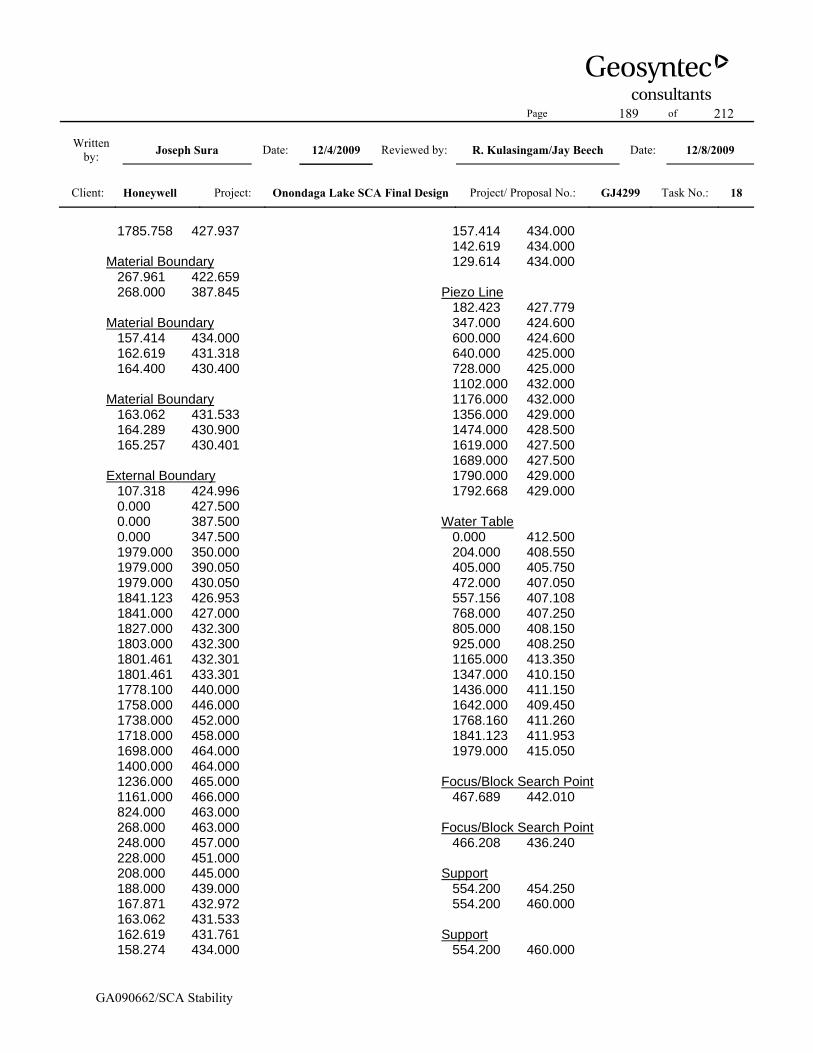
Page 189 of 212
Written by: Joseph Sura Date: 12/4/2009 Reviewed by: R. Kulasingam/Jay Beech Date: 12/8/2009
Client: Honeywell Project: Onondaga Lake SCA Final Design Project/ Proposal No.: GJ4299 Task No.: 18
GA090662/SCA Stability
1785.758 427.937 Material Boundary 267.961 422.659 268.000 387.845 Material Boundary 157.414 434.000 162.619 431.318 164.400 430.400 Material Boundary 163.062 431.533 164.289 430.900 165.257 430.401 External Boundary 107.318 424.996 0.000 427.500 0.000 387.500 0.000 347.500 1979.000 350.000 1979.000 390.050 1979.000 430.050 1841.123 426.953 1841.000 427.000 1827.000 432.300 1803.000 432.300 1801.461 432.301 1801.461 433.301 1778.100 440.000 1758.000 446.000 1738.000 452.000 1718.000 458.000 1698.000 464.000 1400.000 464.000 1236.000 465.000 1161.000 466.000 824.000 463.000 268.000 463.000 248.000 457.000 228.000 451.000 208.000 445.000 188.000 439.000 167.871 432.972 163.062 431.533 162.619 431.761 158.274 434.000
157.414 434.000 142.619 434.000 129.614 434.000 Piezo Line 182.423 427.779 347.000 424.600 600.000 424.600 640.000 425.000 728.000 425.000 1102.000 432.000 1176.000 432.000 1356.000 429.000 1474.000 428.500 1619.000 427.500 1689.000 427.500 1790.000 429.000 1792.668 429.000 Water Table 0.000 412.500 204.000 408.550 405.000 405.750 472.000 407.050 557.156 407.108 768.000 407.250 805.000 408.150 925.000 408.250 1165.000 413.350 1347.000 410.150 1436.000 411.150 1642.000 409.450 1768.160 411.260 1841.123 411.953 1979.000 415.050 Focus/Block Search Point 467.689 442.010 Focus/Block Search Point 466.208 436.240 Support 554.200 454.250 554.200 460.000 Support 554.200 460.000

Page 190 of 212
Written by: Joseph Sura Date: 12/4/2009 Reviewed by: R. Kulasingam/Jay Beech Date: 12/8/2009
Client: Honeywell Project: Onondaga Lake SCA Final Design Project/ Proposal No.: GJ4299 Task No.: 18
GA090662/SCA Stability
268.000 460.000 Support 268.000 454.000 248.000 454.000 Support 248.000 454.000 248.000 448.250 Support 248.000 448.250 493.200 448.250 Support 493.200 454.000 493.200 448.250 Support 268.000 460.000 268.000 454.250 Support 268.000 454.250 554.200 454.250 Support 555.700 454.250 555.700 460.000 Support 555.700 460.000 824.000 460.000 Support 824.000 460.000 840.193 460.144 Support 840.193 460.144 840.193 454.394 Support 840.193 454.394 824.000 454.250 Support 824.000 454.250
555.700 454.250 Support 738.195 454.000 738.195 448.250 Support 739.701 454.000 739.701 448.250 Support 738.195 454.000 494.700 454.000 Support 494.700 454.000 494.700 448.250 Support 494.700 448.250 738.195 448.250 Support 724.201 442.000 724.201 436.250 Support 724.201 436.250 467.700 436.250 Support 467.700 436.250 467.700 442.000 Support 467.700 442.000 724.201 442.000 Support 228.000 448.000 228.000 442.250 Support 248.000 448.000 530.200 448.000 Support 530.200 448.000

Page 191 of 212
Written by: Joseph Sura Date: 12/4/2009 Reviewed by: R. Kulasingam/Jay Beech Date: 12/8/2009
Client: Honeywell Project: Onondaga Lake SCA Final Design Project/ Proposal No.: GJ4299 Task No.: 18
GA090662/SCA Stability
530.200 442.250 Support 531.700 442.250 531.700 448.000 Support 530.200 442.250 228.000 442.250 Support 228.000 448.000 248.000 448.000 Support 208.000 436.250 208.000 442.000 Support 208.000 442.000 228.000 442.000 Support 228.000 442.000 466.200 442.000 Support 466.200 442.000 466.200 436.250 Support 466.200 436.250 208.000 436.250 Support 188.000 430.250 188.000 436.000 Support 188.000 436.000 208.000 436.000 Support 208.000 436.000 506.200 436.000 Support 507.700 436.000
507.700 430.250 Support 506.200 436.000 506.200 430.250 Support 506.200 430.250 188.000 430.250 Support 507.700 430.250 824.200 430.252 Support 824.200 430.252 824.200 436.002 Support 824.200 436.002 507.700 436.000 Support 832.191 442.323 832.191 448.073 Support 833.715 442.336 833.715 448.086 Support 832.191 448.073 824.000 448.000 Support 824.000 448.000 531.700 448.000 Support 531.700 442.250 824.000 442.250 Support 824.000 442.250 832.191 442.323 Support 841.706 460.158

Page 192 of 212
Written by: Joseph Sura Date: 12/4/2009 Reviewed by: R. Kulasingam/Jay Beech Date: 12/8/2009
Client: Honeywell Project: Onondaga Lake SCA Final Design Project/ Proposal No.: GJ4299 Task No.: 18
GA090662/SCA Stability
841.706 454.408 Support 825.700 436.015 825.700 430.265 Support 725.697 442.000 725.697 436.250 Support 725.697 436.250 824.000 436.250 Support 824.000 436.250 982.197 437.658 Support 982.197 437.658 982.197 443.408 Support 982.197 443.408 824.000 442.000 Support 824.000 442.000 725.697 442.000 Support 739.701 448.250 824.000 448.250 Support 824.000 448.250 983.182 449.667 Support 983.182 449.667 983.182 455.417 Support 983.182 455.417 824.000 454.000 Support 824.000 454.000
739.701 454.000 Support 841.706 454.408 1126.178 456.940 Support 1126.178 456.940 1126.178 462.690 Support 1126.178 462.690 841.706 460.158 Support 833.715 448.086 1134.188 450.761 Support 1134.188 450.761 1134.188 445.011 Support 1134.188 445.011 833.715 442.336 Support 825.700 436.015 1142.148 438.832 Support 1142.148 438.832 1142.148 433.082 Support 1142.148 433.082 825.700 430.265 Support 984.724 455.431 984.724 449.681 Support 983.718 443.422 983.718 437.672 Support 983.718 437.672

Page 193 of 212
Written by: Joseph Sura Date: 12/4/2009 Reviewed by: R. Kulasingam/Jay Beech Date: 12/8/2009
Client: Honeywell Project: Onondaga Lake SCA Final Design Project/ Proposal No.: GJ4299 Task No.: 18
GA090662/SCA Stability
1161.000 439.250 Support 1161.000 439.250 1236.000 438.250 Support 1236.000 438.250 1240.193 438.224 Support 1240.193 438.224 1240.193 443.974 Support 1240.193 443.974 1236.000 444.000 Support 1236.000 444.000 1161.000 445.000 Support 1161.000 445.000 983.718 443.422 Support 984.724 455.431 1161.000 457.000 Support 1161.000 457.000 1228.192 456.104 Support 1228.192 456.104 1228.192 450.354 Support 1228.192 450.354 1161.000 451.250 Support 1161.000 451.250 984.724 449.681 Support 268.000 454.000
493.200 454.000 Support 1127.707 462.704 1127.707 456.954 Support 1127.707 462.704 1161.000 463.000 Support 1161.000 463.000 1236.000 462.000 Support 1236.000 462.000 1400.000 461.000 Support 1400.000 461.000 1412.195 461.000 Support 1412.195 461.000 1412.195 455.250 Support 1412.195 455.250 1400.000 455.250 Support 1400.000 455.250 1236.000 456.250 Support 1236.000 456.250 1161.000 457.250 Support 1161.000 457.250 1127.707 456.954 Support 1135.719 450.775 1135.719 445.025 Support 1135.719 450.775

Page 194 of 212
Written by: Joseph Sura Date: 12/4/2009 Reviewed by: R. Kulasingam/Jay Beech Date: 12/8/2009
Client: Honeywell Project: Onondaga Lake SCA Final Design Project/ Proposal No.: GJ4299 Task No.: 18
GA090662/SCA Stability
1161.000 451.000 Support 1161.000 445.250 1135.719 445.025 Support 1161.000 445.250 1236.000 444.250 Support 1236.000 444.250 1400.000 443.250 Support 1400.000 443.250 1436.205 443.250 Support 1436.205 443.250 1436.205 449.000 Support 1437.780 449.000 1437.780 443.250 Support 1436.205 449.000 1400.000 449.000 Support 1400.000 449.000 1236.000 450.000 Support 1236.000 450.000 1161.000 451.000 Support 1229.723 456.084 1229.723 450.334 Support 1229.723 450.334 1236.000 450.250 Support 1236.000 456.000
1229.723 456.084 Support 1236.000 456.000 1400.000 455.000 Support 1400.000 455.000 1473.204 455.000 Support 1473.204 455.000 1473.204 449.250 Support 1474.788 449.250 1474.788 455.000 Support 1473.204 449.250 1400.000 449.250 Support 1400.000 449.250 1236.000 450.250 Support 1241.724 438.215 1241.724 443.965 Support 1143.812 438.847 1143.812 433.097 Support 1143.812 433.097 1161.000 433.250 Support 1161.000 439.000 1143.812 438.847 Support 1161.000 439.000 1236.000 438.000 Support 1236.000 438.000

Page 195 of 212
Written by: Joseph Sura Date: 12/4/2009 Reviewed by: R. Kulasingam/Jay Beech Date: 12/8/2009
Client: Honeywell Project: Onondaga Lake SCA Final Design Project/ Proposal No.: GJ4299 Task No.: 18
GA090662/SCA Stability
1400.000 437.000 Support 1400.000 437.000 1460.199 437.000 Support 1460.199 437.000 1460.199 431.250 Support 1461.784 431.250 1461.784 437.000 Support 1460.199 431.250 1400.000 431.250 Support 1400.000 431.250 1236.000 432.250 Support 1236.000 432.250 1161.000 433.250 Support 1241.724 438.215 1400.000 437.250 Support 1400.000 437.250 1498.182 437.250 Support 1498.182 443.000 1498.182 437.250 Support 1499.766 437.250 1499.766 443.000 Support 1498.182 443.000 1400.000 443.000 Support 1400.000 443.000
1241.724 443.965 Support 1413.743 461.000 1413.743 455.250 Support 1413.743 461.000 1698.000 461.000 Support 1698.000 461.000 1698.000 455.250 Support 1698.000 455.250 1413.743 455.250 Support 1474.788 449.250 1718.000 449.250 Support 1718.000 449.250 1718.000 455.000 Support 1698.000 455.000 1474.788 455.000 Support 1461.784 431.250 1778.100 431.250 Support 1778.100 431.250 1778.100 437.000 Support 1758.000 437.000 1461.784 437.000 Support 1437.780 443.250 1738.000 443.250 Support 1738.000 443.250

Page 196 of 212
Written by: Joseph Sura Date: 12/4/2009 Reviewed by: R. Kulasingam/Jay Beech Date: 12/8/2009
Client: Honeywell Project: Onondaga Lake SCA Final Design Project/ Proposal No.: GJ4299 Task No.: 18
GA090662/SCA Stability
1738.000 449.000 Support 1718.000 449.000 1437.780 449.000 Support 1499.766 437.250 1758.000 437.250 Support 1758.000 437.250 1758.000 443.000 Support 1738.000 443.000 1499.766 443.000 Support 1718.000 455.000 1698.000 455.000 Support 1718.000 449.000 1738.000 449.000 Support 1738.000 443.000 1758.000 443.000 Support 1758.000 437.000 1778.100 437.000

Page 197 of 212
Written by: Joseph Sura Date: 12/4/2009 Reviewed by: R. Kulasingam/Jay Beech Date: 12/8/2009
Client: Honeywell Project: Onondaga Lake SCA Final Design Project/ Proposal No.: GJ4299 Task No.: 18
GA090662/SCA Stability
Slide Analysis Information Document Name File Name: eastwest_cover_liner_lab Project Settings Project Title: SLIDE - An Interactive Slope Stability Program Failure Direction: Right to Left Units of Measurement: Imperial Units Pore Fluid Unit Weight: 62.4 lb/ft3 Groundwater Method: Water Surfaces Data Output: Standard Calculate Excess Pore Pressure: Off Allow Ru with Water Surfaces or Grids: Off Random Numbers: Pseudo-random Seed Random Number Seed: 10116 Random Number Generation Method: Park and Miller v.3 Analysis Methods Analysis Methods used: Bishop simplified Janbu simplified Spencer Number of slices: 25 Tolerance: 0.005 Maximum number of iterations: 50 Surface Options Surface Type: Non-Circular Block Search Number of Surfaces: 5000 Pseudo-Random Surfaces: Enabled Convex Surfaces Only: Disabled Left Projection Angle (Start Angle): 95 Left Projection Angle (End Angle): 175 Right Projection Angle (Start Angle): 5 Right Projection Angle (End Angle): 85 Minimum Elevation: Not Defined Minimum Depth: Not Defined Material Properties Material: Final Cover Soil
Strength Type: Mohr-Coulomb Unit Weight: 120 lb/ft3 Cohesion: 0 psf Friction Angle: 30 degrees Water Surface: Water Table Custom Hu value: 1 Material: Dike Soil Strength Type: Mohr-Coulomb Unit Weight: 120 lb/ft3 Cohesion: 0 psf Friction Angle: 35 degrees Water Surface: Water Table Custom Hu value: 1 Material: Gravel Strength Type: Mohr-Coulomb Unit Weight: 120 lb/ft3 Cohesion: 0 psf Friction Angle: 38 degrees Water Surface: Piezometric Line 1 Custom Hu value: 1 Material: SOLW (undrained) Strength Type: Discrete function Unit Weight: 82 lb/ft3 Water Surface: Water Table Custom Hu value: 1 Material: Dredge Material Strength Type: Mohr-Coulomb Unit Weight: 86 lb/ft3 Cohesion: 0 psf Friction Angle: 15 degrees Water Surface: Water Table Custom Hu value: 1 Material: Tube-Tube Interface (Horizontal) Strength Type: Mohr-Coulomb Unit Weight: 86 lb/ft3 Cohesion: 0 psf Friction Angle: 15 degrees Water Surface: Water Table Custom Hu value: 1 Material: Tub-Tube Interface (Vertical) Strength Type: Mohr-Coulomb Unit Weight: 43 lb/ft3

Page 198 of 212
Written by: Joseph Sura Date: 12/4/2009 Reviewed by: R. Kulasingam/Jay Beech Date: 12/8/2009
Client: Honeywell Project: Onondaga Lake SCA Final Design Project/ Proposal No.: GJ4299 Task No.: 18
GA090662/SCA Stability
Cohesion: 0 psf Friction Angle: 0.1 degrees Water Surface: Water Table Custom Hu value: 1 Material: Tube-Gravel Interface Strength Type: Mohr-Coulomb Unit Weight: 86 lb/ft3 Cohesion: 0 psf Friction Angle: 24 degrees Water Surface: Water Table Custom Hu value: 1 Material: Liner Strength Type: Mohr-Coulomb Unit Weight: 100 lb/ft3 Cohesion: 0 psf Friction Angle: 19 degrees Water Surface: Water Table Custom Hu value: 1 Material: Foundation Strength Type: Mohr-Coulomb Unit Weight: 120 lb/ft3 Cohesion: 0 psf Friction Angle: 37 degrees Water Surface: Water Table Custom Hu value: 1 Support Properties Support: Geotube Geotube Support Type: GeoTextile Force Application: Passive Force Orientation: Tangent to Slip Surface Anchorage: Both Ends Shear Strength Model: Linear Strip Coverage: 100 percent Tensile Strength: 1600 lb/ft Pullout Strength Adhesion: 5 lb/ft2 Pullout Strength Friction Angle: 40 degrees Global Minimums Method: bishop simplified FS: 1.819170 Axis Location: 191.041, 570.041 Left Slip Surface Endpoint: 161.508, 431.016
Right Slip Surface Endpoint: 284.542, 463.000 Resisting Moment=1.01275e+007 lb-ft Driving Moment=5.56707e+006 lb-ft Method: janbu simplified FS: 1.813810 Axis Location: 191.041, 570.041 Left Slip Surface Endpoint: 161.508, 431.016 Right Slip Surface Endpoint: 284.542, 463.000 Resisting Horizontal Force=66479.5 lb Driving Horizontal Force=36651.9 lb Method: spencer FS: 1.511940 Axis Location: 180.031, 558.609 Left Slip Surface Endpoint: 152.083, 434.000 Right Slip Surface Endpoint: 262.949, 461.485 Resisting Moment=3.88774e+007 lb-ft Driving Moment=2.57136e+007 lb-ft Resisting Horizontal Force=176559 lb Driving Horizontal Force=116776 lb Valid / Invalid Surfaces Method: bishop simplified Number of Valid Surfaces: 3139 Number of Invalid Surfaces: 1861 Error Codes: Error Code -105 reported for 357 surfaces Error Code -107 reported for 186 surfaces Error Code -108 reported for 379 surfaces Error Code -110 reported for 285 surfaces Error Code -112 reported for 654 surfaces Method: janbu simplified Number of Valid Surfaces: 3045 Number of Invalid Surfaces: 1955 Error Codes: Error Code -105 reported for 357 surfaces Error Code -107 reported for 186 surfaces Error Code -108 reported for 507 surfaces Error Code -110 reported for 285 surfaces Error Code -112 reported for 620 surfaces Method: spencer Number of Valid Surfaces: 1412 Number of Invalid Surfaces: 3588 Error Codes:

Page 199 of 212
Written by: Joseph Sura Date: 12/4/2009 Reviewed by: R. Kulasingam/Jay Beech Date: 12/8/2009
Client: Honeywell Project: Onondaga Lake SCA Final Design Project/ Proposal No.: GJ4299 Task No.: 18
GA090662/SCA Stability
Error Code -105 reported for 357 surfaces Error Code -107 reported for 186 surfaces Error Code -108 reported for 521 surfaces Error Code -110 reported for 285 surfaces Error Code -111 reported for 1573 surfaces Error Code -112 reported for 666 surfaces

Page 200 of 212
Written by: Joseph Sura Date: 12/4/2009 Reviewed by: R. Kulasingam/Jay Beech Date: 12/8/2009
Client: Honeywell Project: Onondaga Lake SCA Final Design Project/ Proposal No.: GJ4299 Task No.: 18
GA090662/SCA Stability
Slide Analysis Information Document Name File Name: eastwest_cover_global_su_lab Project Settings Project Title: SLIDE - An Interactive Slope Stability Program Failure Direction: Right to Left Units of Measurement: Imperial Units Pore Fluid Unit Weight: 62.4 lb/ft3 Groundwater Method: Water Surfaces Data Output: Standard Calculate Excess Pore Pressure: Off Allow Ru with Water Surfaces or Grids: Off Random Numbers: Pseudo-random Seed Random Number Seed: 10116 Random Number Generation Method: Park and Miller v.3 Analysis Methods Analysis Methods used: Bishop simplified Janbu simplified Spencer Number of slices: 25 Tolerance: 0.005 Maximum number of iterations: 50 Surface Options Surface Type: Circular Search Method: Grid Search Radius increment: 10 Composite Surfaces: Disabled Reverse Curvature: Create Tension Crack Minimum Elevation: Not Defined Minimum Depth: Not Defined Material Properties Material: Final Cover Soil Strength Type: Mohr-Coulomb Unit Weight: 120 lb/ft3 Cohesion: 0 psf Friction Angle: 30 degrees
Water Surface: Water Table Custom Hu value: 1 Material: Dike Soil Strength Type: Mohr-Coulomb Unit Weight: 120 lb/ft3 Cohesion: 0 psf Friction Angle: 35 degrees Water Surface: Water Table Custom Hu value: 1 Material: Gravel Strength Type: Mohr-Coulomb Unit Weight: 120 lb/ft3 Cohesion: 0 psf Friction Angle: 38 degrees Water Surface: Piezometric Line 1 Custom Hu value: 1 Material: SOLW (undrained) Strength Type: Discrete function Unit Weight: 82 lb/ft3 Water Surface: Water Table Custom Hu value: 1 Material: Dredge Material Strength Type: Mohr-Coulomb Unit Weight: 86 lb/ft3 Cohesion: 0 psf Friction Angle: 15 degrees Water Surface: Water Table Custom Hu value: 1 Material: Tube-Tube Interface (Horizontal) Strength Type: Mohr-Coulomb Unit Weight: 86 lb/ft3 Cohesion: 0 psf Friction Angle: 15 degrees Water Surface: Water Table Custom Hu value: 1 Material: Tub-Tube Interface (Vertical) Strength Type: Mohr-Coulomb Unit Weight: 43 lb/ft3 Cohesion: 0 psf Friction Angle: 0.1 degrees Water Surface: Water Table Custom Hu value: 1
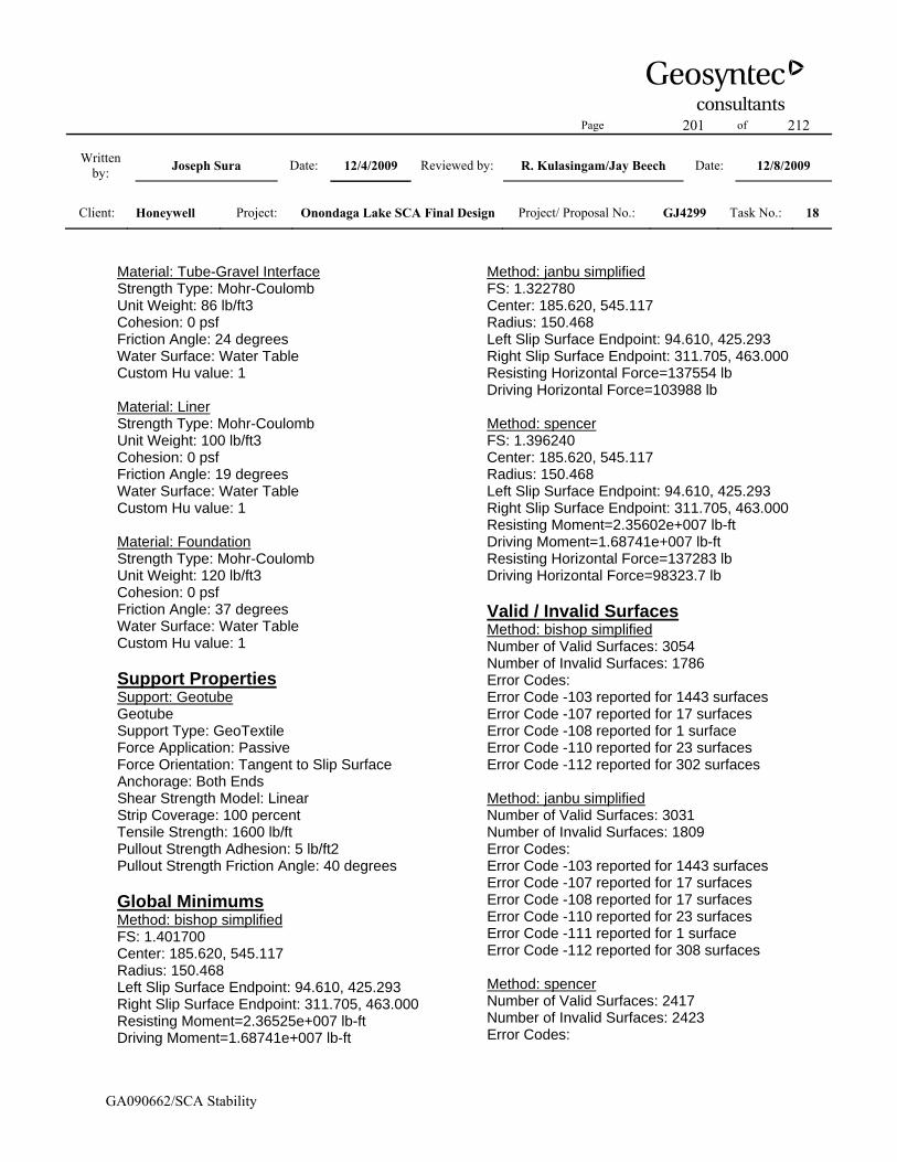
Page 201 of 212
Written by: Joseph Sura Date: 12/4/2009 Reviewed by: R. Kulasingam/Jay Beech Date: 12/8/2009
Client: Honeywell Project: Onondaga Lake SCA Final Design Project/ Proposal No.: GJ4299 Task No.: 18
GA090662/SCA Stability
Material: Tube-Gravel Interface Strength Type: Mohr-Coulomb Unit Weight: 86 lb/ft3 Cohesion: 0 psf Friction Angle: 24 degrees Water Surface: Water Table Custom Hu value: 1 Material: Liner Strength Type: Mohr-Coulomb Unit Weight: 100 lb/ft3 Cohesion: 0 psf Friction Angle: 19 degrees Water Surface: Water Table Custom Hu value: 1 Material: Foundation Strength Type: Mohr-Coulomb Unit Weight: 120 lb/ft3 Cohesion: 0 psf Friction Angle: 37 degrees Water Surface: Water Table Custom Hu value: 1 Support Properties Support: Geotube Geotube Support Type: GeoTextile Force Application: Passive Force Orientation: Tangent to Slip Surface Anchorage: Both Ends Shear Strength Model: Linear Strip Coverage: 100 percent Tensile Strength: 1600 lb/ft Pullout Strength Adhesion: 5 lb/ft2 Pullout Strength Friction Angle: 40 degrees Global Minimums Method: bishop simplified FS: 1.401700 Center: 185.620, 545.117 Radius: 150.468 Left Slip Surface Endpoint: 94.610, 425.293 Right Slip Surface Endpoint: 311.705, 463.000 Resisting Moment=2.36525e+007 lb-ft Driving Moment=1.68741e+007 lb-ft
Method: janbu simplified FS: 1.322780 Center: 185.620, 545.117 Radius: 150.468 Left Slip Surface Endpoint: 94.610, 425.293 Right Slip Surface Endpoint: 311.705, 463.000 Resisting Horizontal Force=137554 lb Driving Horizontal Force=103988 lb Method: spencer FS: 1.396240 Center: 185.620, 545.117 Radius: 150.468 Left Slip Surface Endpoint: 94.610, 425.293 Right Slip Surface Endpoint: 311.705, 463.000 Resisting Moment=2.35602e+007 lb-ft Driving Moment=1.68741e+007 lb-ft Resisting Horizontal Force=137283 lb Driving Horizontal Force=98323.7 lb Valid / Invalid Surfaces Method: bishop simplified Number of Valid Surfaces: 3054 Number of Invalid Surfaces: 1786 Error Codes: Error Code -103 reported for 1443 surfaces Error Code -107 reported for 17 surfaces Error Code -108 reported for 1 surface Error Code -110 reported for 23 surfaces Error Code -112 reported for 302 surfaces Method: janbu simplified Number of Valid Surfaces: 3031 Number of Invalid Surfaces: 1809 Error Codes: Error Code -103 reported for 1443 surfaces Error Code -107 reported for 17 surfaces Error Code -108 reported for 17 surfaces Error Code -110 reported for 23 surfaces Error Code -111 reported for 1 surface Error Code -112 reported for 308 surfaces Method: spencer Number of Valid Surfaces: 2417 Number of Invalid Surfaces: 2423 Error Codes:
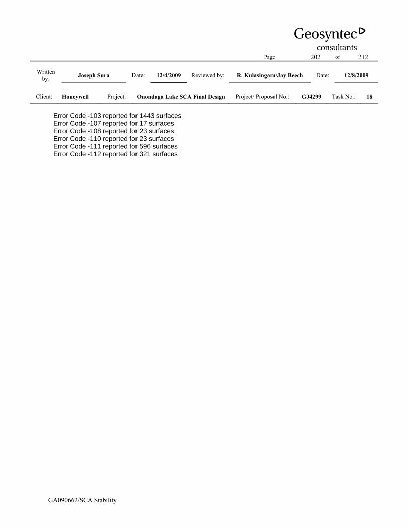
Page 202 of 212
Written by: Joseph Sura Date: 12/4/2009 Reviewed by: R. Kulasingam/Jay Beech Date: 12/8/2009
Client: Honeywell Project: Onondaga Lake SCA Final Design Project/ Proposal No.: GJ4299 Task No.: 18
GA090662/SCA Stability
Error Code -103 reported for 1443 surfaces Error Code -107 reported for 17 surfaces Error Code -108 reported for 23 surfaces Error Code -110 reported for 23 surfaces Error Code -111 reported for 596 surfaces Error Code -112 reported for 321 surfaces

Page 203 of 212
Written by: Joseph Sura Date: 12/4/2009 Reviewed by: R. Kulasingam/Jay Beech Date: 12/8/2009
Client: Honeywell Project: Onondaga Lake SCA Final Design Project/ Proposal No.: GJ4299 Task No.: 18
GA090662/SCA Stability
Slide Analysis Information Document Name File Name: eastwest_cover_global_u75_lab Project Settings Project Title: SLIDE - An Interactive Slope Stability Program Failure Direction: Right to Left Units of Measurement: Imperial Units Pore Fluid Unit Weight: 62.4 lb/ft3 Groundwater Method: Water Surfaces Data Output: Standard Calculate Excess Pore Pressure: Off Allow Ru with Water Surfaces or Grids: Off Random Numbers: Pseudo-random Seed Random Number Seed: 10116 Random Number Generation Method: Park and Miller v.3 Analysis Methods Analysis Methods used: Bishop simplified Janbu simplified Spencer Number of slices: 25 Tolerance: 0.005 Maximum number of iterations: 50 Surface Options Surface Type: Circular Search Method: Grid Search Radius increment: 10 Composite Surfaces: Disabled Reverse Curvature: Create Tension Crack Minimum Elevation: Not Defined Minimum Depth: Not Defined Material Properties Material: Final Cover Soil Strength Type: Mohr-Coulomb Unit Weight: 120 lb/ft3 Cohesion: 0 psf Friction Angle: 30 degrees
Water Surface: Water Table Custom Hu value: 1 Material: Dike Soil Strength Type: Mohr-Coulomb Unit Weight: 120 lb/ft3 Cohesion: 0 psf Friction Angle: 35 degrees Water Surface: Water Table Custom Hu value: 1 Material: Gravel Strength Type: Mohr-Coulomb Unit Weight: 120 lb/ft3 Cohesion: 0 psf Friction Angle: 38 degrees Water Surface: Piezometric Line 1 Custom Hu value: 1 Material: SOLW (undrained) Strength Type: Discrete function Unit Weight: 82 lb/ft3 Water Surface: Water Table Custom Hu value: 1 Material: Dredge Material Strength Type: Mohr-Coulomb Unit Weight: 86 lb/ft3 Cohesion: 0 psf Friction Angle: 15 degrees Water Surface: Water Table Custom Hu value: 1 Material: Tube-Tube Interface (Horizontal) Strength Type: Mohr-Coulomb Unit Weight: 86 lb/ft3 Cohesion: 0 psf Friction Angle: 15 degrees Water Surface: Water Table Custom Hu value: 1 Material: Tub-Tube Interface (Vertical) Strength Type: Mohr-Coulomb Unit Weight: 43 lb/ft3 Cohesion: 0 psf Friction Angle: 0.1 degrees Water Surface: Water Table Custom Hu value: 1

Page 204 of 212
Written by: Joseph Sura Date: 12/4/2009 Reviewed by: R. Kulasingam/Jay Beech Date: 12/8/2009
Client: Honeywell Project: Onondaga Lake SCA Final Design Project/ Proposal No.: GJ4299 Task No.: 18
GA090662/SCA Stability
Material: Tube-Gravel Interface Strength Type: Mohr-Coulomb Unit Weight: 86 lb/ft3 Cohesion: 0 psf Friction Angle: 24 degrees Water Surface: Water Table Custom Hu value: 1 Material: Liner Strength Type: Mohr-Coulomb Unit Weight: 100 lb/ft3 Cohesion: 0 psf Friction Angle: 19 degrees Water Surface: Water Table Custom Hu value: 1 Material: Foundation Strength Type: Mohr-Coulomb Unit Weight: 120 lb/ft3 Cohesion: 0 psf Friction Angle: 37 degrees Water Surface: Water Table Custom Hu value: 1 Material: SOLW U=75% Strength Type: Discrete function Unit Weight: 82 lb/ft3 Water Surface: Water Table Custom Hu value: 1 Support Properties Support: Geotube Geotube Support Type: GeoTextile Force Application: Passive Force Orientation: Tangent to Slip Surface Anchorage: Both Ends Shear Strength Model: Linear Strip Coverage: 100 percent Tensile Strength: 1600 lb/ft Pullout Strength Adhesion: 5 lb/ft2 Pullout Strength Friction Angle: 40 degrees Global Minimums Method: bishop simplified FS: 1.425720
Center: 177.623, 545.117 Radius: 149.072 Left Slip Surface Endpoint: 88.756, 425.429 Right Slip Surface Endpoint: 302.039, 463.000 Resisting Moment=2.27764e+007 lb-ft Driving Moment=1.59753e+007 lb-ft Method: janbu simplified FS: 1.340700 Center: 177.623, 535.909 Radius: 141.842 Left Slip Surface Endpoint: 88.663, 425.431 Right Slip Surface Endpoint: 299.292, 463.000 Resisting Horizontal Force=134615 lb Driving Horizontal Force=100407 lb Method: spencer FS: 1.419040 Center: 177.623, 545.117 Radius: 149.072 Left Slip Surface Endpoint: 88.756, 425.429 Right Slip Surface Endpoint: 302.039, 463.000 Resisting Moment=2.26697e+007 lb-ft Driving Moment=1.59753e+007 lb-ft Resisting Horizontal Force=133379 lb Driving Horizontal Force=93992.7 lb Valid / Invalid Surfaces Method: bishop simplified Number of Valid Surfaces: 3053 Number of Invalid Surfaces: 1787 Error Codes: Error Code -103 reported for 1443 surfaces Error Code -107 reported for 17 surfaces Error Code -108 reported for 1 surface Error Code -110 reported for 23 surfaces Error Code -112 reported for 303 surfaces Method: janbu simplified Number of Valid Surfaces: 3029 Number of Invalid Surfaces: 1811 Error Codes: Error Code -103 reported for 1443 surfaces Error Code -107 reported for 17 surfaces Error Code -108 reported for 17 surfaces Error Code -110 reported for 23 surfaces Error Code -111 reported for 1 surface

Page 205 of 212
Written by: Joseph Sura Date: 12/4/2009 Reviewed by: R. Kulasingam/Jay Beech Date: 12/8/2009
Client: Honeywell Project: Onondaga Lake SCA Final Design Project/ Proposal No.: GJ4299 Task No.: 18
GA090662/SCA Stability
Error Code -112 reported for 310 surfaces Method: spencer Number of Valid Surfaces: 2416 Number of Invalid Surfaces: 2424 Error Codes: Error Code -103 reported for 1443 surfaces Error Code -107 reported for 17 surfaces Error Code -108 reported for 23 surfaces Error Code -110 reported for 23 surfaces Error Code -111 reported for 597 surfaces Error Code -112 reported for 321 surfaces

Page 206 of 212
Written by: Joseph Sura Date: 12/4/2009 Reviewed by: R. Kulasingam/Jay Beech Date: 12/8/2009
Client: Honeywell Project: Onondaga Lake SCA Final Design Project/ Proposal No.: GJ4299 Task No.: 18
GA090662/SCA Stability
Slide Analysis Information Document Name File Name: eastwest_cover_longterm_lab Project Settings Project Title: SLIDE - An Interactive Slope Stability Program Failure Direction: Right to Left Units of Measurement: Imperial Units Pore Fluid Unit Weight: 62.4 lb/ft3 Groundwater Method: Water Surfaces Data Output: Standard Calculate Excess Pore Pressure: Off Allow Ru with Water Surfaces or Grids: Off Random Numbers: Pseudo-random Seed Random Number Seed: 10116 Random Number Generation Method: Park and Miller v.3 Analysis Methods Analysis Methods used: Bishop simplified Janbu simplified Spencer Number of slices: 25 Tolerance: 0.005 Maximum number of iterations: 50 Surface Options Surface Type: Circular Search Method: Grid Search Radius increment: 10 Composite Surfaces: Disabled Reverse Curvature: Create Tension Crack Minimum Elevation: Not Defined Minimum Depth: Not Defined Material Properties Material: Final Cover Soil Strength Type: Mohr-Coulomb Unit Weight: 120 lb/ft3 Cohesion: 0 psf Friction Angle: 30 degrees
Water Surface: Water Table Custom Hu value: 1 Material: Dike Soil Strength Type: Mohr-Coulomb Unit Weight: 120 lb/ft3 Cohesion: 0 psf Friction Angle: 35 degrees Water Surface: Water Table Custom Hu value: 1 Material: Gravel Strength Type: Mohr-Coulomb Unit Weight: 120 lb/ft3 Cohesion: 0 psf Friction Angle: 38 degrees Water Surface: Piezometric Line 1 Custom Hu value: 1 Material: SOLW (Drained) Strength Type: Mohr-Coulomb Unit Weight: 82 lb/ft3 Cohesion: 0 psf Friction Angle: 34 degrees Water Surface: Water Table Custom Hu value: 1 Material: Dredge Material (Long) Strength Type: Mohr-Coulomb Unit Weight: 86 lb/ft3 Cohesion: 0 psf Friction Angle: 30 degrees Water Surface: Water Table Custom Hu value: 1 Material: Tube-Tube Interface (Horizontal) Strength Type: Mohr-Coulomb Unit Weight: 86 lb/ft3 Cohesion: 0 psf Friction Angle: 15 degrees Water Surface: Water Table Custom Hu value: 1 Material: Tub-Tube Interface (Vertical) Strength Type: Mohr-Coulomb Unit Weight: 43 lb/ft3 Cohesion: 0 psf Friction Angle: 0.1 degrees
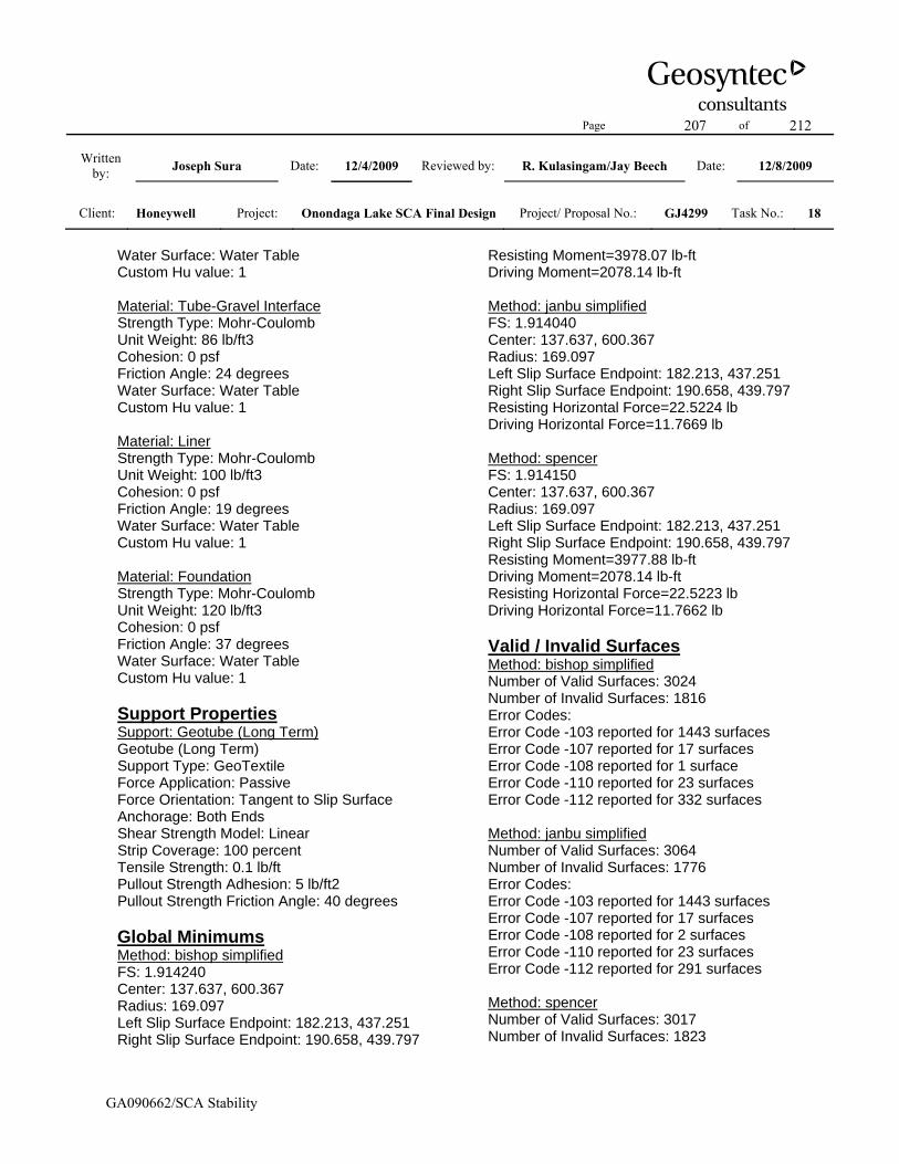
Page 207 of 212
Written by: Joseph Sura Date: 12/4/2009 Reviewed by: R. Kulasingam/Jay Beech Date: 12/8/2009
Client: Honeywell Project: Onondaga Lake SCA Final Design Project/ Proposal No.: GJ4299 Task No.: 18
GA090662/SCA Stability
Water Surface: Water Table Custom Hu value: 1 Material: Tube-Gravel Interface Strength Type: Mohr-Coulomb Unit Weight: 86 lb/ft3 Cohesion: 0 psf Friction Angle: 24 degrees Water Surface: Water Table Custom Hu value: 1 Material: Liner Strength Type: Mohr-Coulomb Unit Weight: 100 lb/ft3 Cohesion: 0 psf Friction Angle: 19 degrees Water Surface: Water Table Custom Hu value: 1 Material: Foundation Strength Type: Mohr-Coulomb Unit Weight: 120 lb/ft3 Cohesion: 0 psf Friction Angle: 37 degrees Water Surface: Water Table Custom Hu value: 1 Support Properties Support: Geotube (Long Term) Geotube (Long Term) Support Type: GeoTextile Force Application: Passive Force Orientation: Tangent to Slip Surface Anchorage: Both Ends Shear Strength Model: Linear Strip Coverage: 100 percent Tensile Strength: 0.1 lb/ft Pullout Strength Adhesion: 5 lb/ft2 Pullout Strength Friction Angle: 40 degrees Global Minimums Method: bishop simplified FS: 1.914240 Center: 137.637, 600.367 Radius: 169.097 Left Slip Surface Endpoint: 182.213, 437.251 Right Slip Surface Endpoint: 190.658, 439.797
Resisting Moment=3978.07 lb-ft Driving Moment=2078.14 lb-ft Method: janbu simplified FS: 1.914040 Center: 137.637, 600.367 Radius: 169.097 Left Slip Surface Endpoint: 182.213, 437.251 Right Slip Surface Endpoint: 190.658, 439.797 Resisting Horizontal Force=22.5224 lb Driving Horizontal Force=11.7669 lb Method: spencer FS: 1.914150 Center: 137.637, 600.367 Radius: 169.097 Left Slip Surface Endpoint: 182.213, 437.251 Right Slip Surface Endpoint: 190.658, 439.797 Resisting Moment=3977.88 lb-ft Driving Moment=2078.14 lb-ft Resisting Horizontal Force=22.5223 lb Driving Horizontal Force=11.7662 lb Valid / Invalid Surfaces Method: bishop simplified Number of Valid Surfaces: 3024 Number of Invalid Surfaces: 1816 Error Codes: Error Code -103 reported for 1443 surfaces Error Code -107 reported for 17 surfaces Error Code -108 reported for 1 surface Error Code -110 reported for 23 surfaces Error Code -112 reported for 332 surfaces Method: janbu simplified Number of Valid Surfaces: 3064 Number of Invalid Surfaces: 1776 Error Codes: Error Code -103 reported for 1443 surfaces Error Code -107 reported for 17 surfaces Error Code -108 reported for 2 surfaces Error Code -110 reported for 23 surfaces Error Code -112 reported for 291 surfaces Method: spencer Number of Valid Surfaces: 3017 Number of Invalid Surfaces: 1823

Page 208 of 212
Written by: Joseph Sura Date: 12/4/2009 Reviewed by: R. Kulasingam/Jay Beech Date: 12/8/2009
Client: Honeywell Project: Onondaga Lake SCA Final Design Project/ Proposal No.: GJ4299 Task No.: 18
GA090662/SCA Stability
Error Codes: Error Code -103 reported for 1443 surfaces Error Code -107 reported for 17 surfaces Error Code -108 reported for 6 surfaces Error Code -110 reported for 23 surfaces Error Code -111 reported for 2 surfaces Error Code -112 reported for 332 surfaces

Page 209 of 212
Written by: Joseph Sura Date: 12/4/2009 Reviewed by: R. Kulasingam/Jay Beech Date: 12/8/2009
Client: Honeywell Project: Onondaga Lake SCA Final Design Project/ Proposal No.: GJ4299 Task No.: 18
GA090662/SCA Stability
Slide Analysis Information Document Name File Name: eastwest_cover_external_lab Project Settings Project Title: SLIDE - An Interactive Slope Stability Program Failure Direction: Right to Left Units of Measurement: Imperial Units Pore Fluid Unit Weight: 62.4 lb/ft3 Groundwater Method: Water Surfaces Data Output: Standard Calculate Excess Pore Pressure: Off Allow Ru with Water Surfaces or Grids: Off Random Numbers: Pseudo-random Seed Random Number Seed: 10116 Random Number Generation Method: Park and Miller v.3 Analysis Methods Analysis Methods used: Bishop simplified Janbu simplified Spencer Number of slices: 25 Tolerance: 0.005 Maximum number of iterations: 50 Surface Options Surface Type: Circular Search Method: Grid Search Radius increment: 10 Composite Surfaces: Disabled Reverse Curvature: Create Tension Crack Minimum Elevation: Not Defined Minimum Depth: Not Defined Material Properties Material: Final Cover Soil Strength Type: Mohr-Coulomb Unit Weight: 120 lb/ft3 Cohesion: 0 psf Friction Angle: 30 degrees
Water Surface: Water Table Custom Hu value: 1 Material: Dike Soil Strength Type: Mohr-Coulomb Unit Weight: 120 lb/ft3 Cohesion: 0 psf Friction Angle: 35 degrees Water Surface: Water Table Custom Hu value: 1 Material: Gravel Strength Type: Mohr-Coulomb Unit Weight: 120 lb/ft3 Cohesion: 0 psf Friction Angle: 38 degrees Water Surface: Piezometric Line 1 Custom Hu value: 1 Material: SOLW (undrained) Strength Type: Discrete function Unit Weight: 82 lb/ft3 Water Surface: Water Table Custom Hu value: 1 Material: Dredge Material Strength Type: Mohr-Coulomb Unit Weight: 86 lb/ft3 Cohesion: 0 psf Friction Angle: 15 degrees Water Surface: Water Table Custom Hu value: 1 Material: Tube-Tube Interface (Horizontal) Strength Type: Mohr-Coulomb Unit Weight: 86 lb/ft3 Cohesion: 0 psf Friction Angle: 15 degrees Water Surface: Water Table Custom Hu value: 1 Material: Tub-Tube Interface (Vertical) Strength Type: Mohr-Coulomb Unit Weight: 43 lb/ft3 Cohesion: 0 psf Friction Angle: 0.1 degrees Water Surface: Water Table Custom Hu value: 1

Page 210 of 212
Written by: Joseph Sura Date: 12/4/2009 Reviewed by: R. Kulasingam/Jay Beech Date: 12/8/2009
Client: Honeywell Project: Onondaga Lake SCA Final Design Project/ Proposal No.: GJ4299 Task No.: 18
GA090662/SCA Stability
Material: Tube-Gravel Interface Strength Type: Mohr-Coulomb Unit Weight: 86 lb/ft3 Cohesion: 0 psf Friction Angle: 24 degrees Water Surface: Water Table Custom Hu value: 1 Material: Liner Strength Type: Mohr-Coulomb Unit Weight: 100 lb/ft3 Cohesion: 0 psf Friction Angle: 19 degrees Water Surface: Water Table Custom Hu value: 1 Material: Foundation Strength Type: Mohr-Coulomb Unit Weight: 120 lb/ft3 Cohesion: 0 psf Friction Angle: 37 degrees Water Surface: Water Table Custom Hu value: 1 Support Properties Support: Geotube Geotube Support Type: GeoTextile Force Application: Passive Force Orientation: Tangent to Slip Surface Anchorage: Both Ends Shear Strength Model: Linear Strip Coverage: 100 percent Tensile Strength: 1600 lb/ft Pullout Strength Adhesion: 5 lb/ft2 Pullout Strength Friction Angle: 40 degrees Global Minimums Method: bishop simplified FS: 7.070290 Center: -4.256, 5490.384 Radius: 5102.085 Left Slip Surface Endpoint: -698.188, 435.710 Right Slip Surface Endpoint: 867.871, 463.391 Resisting Moment=5.67039e+009 lb-ft Driving Moment=8.02003e+008 lb-ft
Method: janbu simplified FS: 7.073590 Center: -4.256, 5490.384 Radius: 5102.085 Left Slip Surface Endpoint: -698.188, 435.710 Right Slip Surface Endpoint: 867.871, 463.391 Resisting Horizontal Force=1.1071e+006 lb Driving Horizontal Force=156511 lb Method: spencer FS: 7.070600 Center: -4.256, 5490.384 Radius: 5102.085 Left Slip Surface Endpoint: -698.188, 435.710 Right Slip Surface Endpoint: 867.871, 463.391 Resisting Moment=5.67065e+009 lb-ft Driving Moment=8.02003e+008 lb-ft Resisting Horizontal Force=1.10715e+006 lb Driving Horizontal Force=156585 lb Valid / Invalid Surfaces Method: bishop simplified Number of Valid Surfaces: 1229 Number of Invalid Surfaces: 3578 Error Codes: Error Code -101 reported for 46 surfaces Error Code -110 reported for 463 surfaces Error Code -1000 reported for 3069 surfaces Method: janbu simplified Number of Valid Surfaces: 1229 Number of Invalid Surfaces: 3578 Error Codes: Error Code -101 reported for 46 surfaces Error Code -110 reported for 463 surfaces Error Code -1000 reported for 3069 surfaces Method: spencer Number of Valid Surfaces: 1228 Number of Invalid Surfaces: 3579 Error Codes: Error Code -101 reported for 46 surfaces Error Code -110 reported for 463 surfaces Error Code -111 reported for 1 surface Error Code -1000 reported for 3069 surfaces

Page 211 of 212
Written by: Joseph Sura Date: 12/4/2009 Reviewed by: R. Kulasingam/Jay Beech Date: 12/8/2009
Client: Honeywell Project: Onondaga Lake SCA Final Design Project/ Proposal No.: GJ4299 Task No.: 18
GA090662/SCA Stability
Slide Analysis Information
Document Name File Name: eastwest_cover_external_longterm_lab Project Settings Project Title: SLIDE - An Interactive Slope Stability Program Failure Direction: Right to Left Units of Measurement: Imperial Units Pore Fluid Unit Weight: 62.4 lb/ft3 Groundwater Method: Water Surfaces Data Output: Standard Calculate Excess Pore Pressure: Off Allow Ru with Water Surfaces or Grids: Off Random Numbers: Pseudo-random Seed Random Number Seed: 10116 Random Number Generation Method: Park and Miller v.3 Analysis Methods Analysis Methods used: Bishop simplified Janbu simplified Spencer Number of slices: 25 Tolerance: 0.005 Maximum number of iterations: 50 Surface Options Surface Type: Circular Search Method: Grid Search Radius increment: 10 Composite Surfaces: Disabled Reverse Curvature: Create Tension Crack Minimum Elevation: Not Defined Minimum Depth: Not Defined Material Properties Material: Final Cover Soil Strength Type: Mohr-Coulomb Unit Weight: 120 lb/ft3 Cohesion: 0 psf Friction Angle: 30 degrees
Water Surface: Water Table Custom Hu value: 1 Material: Dike Soil Strength Type: Mohr-Coulomb Unit Weight: 120 lb/ft3 Cohesion: 0 psf Friction Angle: 35 degrees Water Surface: Water Table Custom Hu value: 1 Material: Gravel Strength Type: Mohr-Coulomb Unit Weight: 120 lb/ft3 Cohesion: 0 psf Friction Angle: 38 degrees Water Surface: Piezometric Line 1 Custom Hu value: 1 Material: SOLW (Drained) Strength Type: Mohr-Coulomb Unit Weight: 82 lb/ft3 Cohesion: 0 psf Friction Angle: 34 degrees Water Surface: Water Table Custom Hu value: 1 Material: Dredge Material (Long) Strength Type: Mohr-Coulomb Unit Weight: 86 lb/ft3 Cohesion: 0 psf Friction Angle: 30 degrees Water Surface: Water Table Custom Hu value: 1 Material: Tube-Tube Interface (Horizontal) Strength Type: Mohr-Coulomb Unit Weight: 86 lb/ft3 Cohesion: 0 psf Friction Angle: 15 degrees Water Surface: Water Table Custom Hu value: 1 Material: Tub-Tube Interface (Vertical) Strength Type: Mohr-Coulomb Unit Weight: 43 lb/ft3 Cohesion: 0 psf Friction Angle: 0.1 degrees

Page 212 of 212
Written by: Joseph Sura Date: 12/4/2009 Reviewed by: R. Kulasingam/Jay Beech Date: 12/8/2009
Client: Honeywell Project: Onondaga Lake SCA Final Design Project/ Proposal No.: GJ4299 Task No.: 18
GA090662/SCA Stability
Water Surface: Water Table Custom Hu value: 1 Material: Tube-Gravel Interface Strength Type: Mohr-Coulomb Unit Weight: 86 lb/ft3 Cohesion: 0 psf Friction Angle: 24 degrees Water Surface: Water Table Custom Hu value: 1 Material: Liner Strength Type: Mohr-Coulomb Unit Weight: 100 lb/ft3 Cohesion: 0 psf Friction Angle: 19 degrees Water Surface: Water Table Custom Hu value: 1 Material: Foundation Strength Type: Mohr-Coulomb Unit Weight: 120 lb/ft3 Cohesion: 0 psf Friction Angle: 37 degrees Water Surface: Water Table Custom Hu value: 1 Support Properties Support: Geotube (Long Term) Geotube (Long Term) Support Type: GeoTextile Force Application: Passive Force Orientation: Tangent to Slip Surface Anchorage: Both Ends Shear Strength Model: Linear Strip Coverage: 100 percent Tensile Strength: 0.1 lb/ft Pullout Strength Adhesion: 5 lb/ft2 Pullout Strength Friction Angle: 40 degrees Global Minimums Method: bishop simplified FS: 11.956800 Center: -516.970, 6468.046 Radius: 6107.435 Left Slip Surface Endpoint: -867.917, 370.702 Right Slip Surface Endpoint: 596.668, 463.000
Resisting Moment=2.0544e+010 lb-ft Driving Moment=1.71819e+009 lb-ft Method: janbu simplified FS: 11.903600 Center: -516.970, 6468.046 Radius: 6107.435 Left Slip Surface Endpoint: -867.917, 370.702 Right Slip Surface Endpoint: 596.668, 463.000 Resisting Horizontal Force=3.35325e+006 lb Driving Horizontal Force=281702 lb Method: spencer FS: 11.955500 Center: -516.970, 6468.046 Radius: 6107.435 Left Slip Surface Endpoint: -867.917, 370.702 Right Slip Surface Endpoint: 596.668, 463.000 Resisting Moment=2.05419e+010 lb-ft Driving Moment=1.71819e+009 lb-ft Resisting Horizontal Force=3.35407e+006 lb Driving Horizontal Force=280545 lb Valid / Invalid Surfaces Method: bishop simplified Number of Valid Surfaces: 1229 Number of Invalid Surfaces: 3578 Error Codes: Error Code -101 reported for 46 surfaces Error Code -110 reported for 463 surfaces Error Code -1000 reported for 3069 surfaces Method: janbu simplified Number of Valid Surfaces: 1229 Number of Invalid Surfaces: 3578 Error Codes: Error Code -101 reported for 46 surfaces Error Code -110 reported for 463 surfaces Error Code -1000 reported for 3069 surfaces Method: spencer Number of Valid Surfaces: 1229 Number of Invalid Surfaces: 3578 Error Codes: Error Code -101 reported for 46 surfaces Error Code -110 reported for 463 surfaces Error Code -1000 reported for 3069 surfaces