draft draft final report for project entitled: impact of
TRANSCRIPT

DRAFT
Draft Final Report for Project Entitled:
Impact of Spray Foam Insulation on Durability of Plywood and OSB Roof Decks
Performance Period: 1/6/2014 – 6/15/2014
Submitted on
June 15, 2014
Presented to the
Florida Building Commission State of Florida Department of Business and Professional Regulation
by
Forrest J. Masters, Ph.D., P.E., [email protected], (352) 392-9537 x 1505, PI Kurtis R. Gurley, Ph.D., [email protected], (352) 392-9537 x 1508
David O. Prevatt, Ph.D., P.E. (MA), [email protected], (352) 392-9537 x 1498
Designated Project Leader: David O. Prevatt
Engineering School for Sustainable Infrastructure & Environment

Impact of Spray Foam Insulation on Durability of
Plywood and OSB Roof Decks
16 June 2015
ii
1 EXECUTIVE SUMMARY
This is a draft final report. The final version will be submitted prior to the end of the project
performance period after the Roofing Technical Advisory Committee (TAC) provides feedback.
The project goal is to prepare a state-of the art review of the literature on wood roof decks
insulated with spray-applied foam, experimentally evaluate the relative drying characteristics of
wood roof deck configurations and to inspect existing Florida homes with installed spray-foam
insulated roof decks.
The March 20, 2015 interim report presented a comprehensive review of literature pertaining
to spray foam installation and moisture issues comprising over 85 peer-reviewed papers and
reports (http://bit.ly/1Skdele). The formation of the Advisory Panel and draft Experimental
Research Plans (ERPs) were presented to the Roofing Technical Advisory Committee. As of
June 15, Experimental Research Plans (ERP) 1, 2, and 3a have been completed, and ERP 3b and
ERP 4 are scheduled to be complete by June 25th and results will be presented to the TAC at that
time. This report presents the results and analysis of all ERPs. This report will be appended as
ERP 3B and 4 are completed.
In the scope of work in ERP 2, the research team surveyed the roofs of two Orlando, FL
homes that have closed cell spray foam installed. Measurements revealed both roof decks had
low moisture content values of less than 6%. The attic temperatures were approximately 30
degrees cooler, and asphalt shingle temperature 21 degrees warmer than in another house that did
not have spray foam insulation. The team noted unlike the roofs brought to our attention
experienced water leaks and sheathing damage, these roofs were geometrically simple shapes,
without roof dormers, penetrations or other irregularities.
From ERP 3 experimental testing results showed that roofing samples made with closed cell
foam insulation dried more slowly than samples having open cell foam insulation or no
insulation. There was little difference between drying rate of the open cell foam insulation
samples and samples with no insulation installed. Among the choices of roofing underlayment
samples with self-adhered membrane underlayment exhibited the slowest drying rate. There was
no significant difference in sample drying rates for samples having 1-ply versus 2-ply 30#
asphaltic felt underlayments.
One surprising observation in our ERP 3b (Point-source water leakage tests), was that
oriented strand board (OSB) sheathing retained much higher moisture levels than did the
plywood sheathing. Additionally, the self-adhered membrane underlayment was not as effective
at restricting the spread of moisture travel throughout the sheathing specimens.
Major Recommendations and Future Work
The drying rates of plywood and OSB deserve further study particularly in relation to
values used in hygrothermal analyses (WUFI 5.0 etc.). Generally numerical analysis
software use similar draying rates for OSB and plywood roof sheathing. However our
experimental testing shows that plywood tends to have lower moisture contents over
prolonged exposures to a leak. Further research is needed to determine whether

Impact of Spray Foam Insulation on Durability of
Plywood and OSB Roof Decks
16 June 2015
iii
recommendations for specific sheathing types are warranted in the Florida Building
Code.
Despite efforts of the research team and its Advisory Panel members only three examples
of water related deterioration in SPF insulated roofs were found, and none of these cases
were provided in form of engineering (forensic) reports with through investigative
procedures. As such, the research team lacks sufficient evidence of widespread and
systemic failures of spray foam insulated wood roof decks to conclude that premature
deterioration of wood roof decks insulated with spray foam insulation is a problem in
Florida. Continued efforts are needed to identify other cases of moisture deterioration in
SPF roofs and perform forensic analysis to ascertain the primary causes of the
deterioration. The findings of this research would guide the Florida Building Commission
in deciding whether to address moisture issues with SPF roofs in more detail in the
building code.
In two of the three homes where water was discovered at the interface between wood roof
decks and spray insulation, the severely deteriorated sheathing was adjacent to roof
dormers with window and wall flashing details, which may have failed and provided a
passage for water to enter the roof system. The extensive deterioration suggests, high
volume of water leakage occurred for extended periods. The research team recommends
that non-destructive test procedures be developed to detect water leakage in roofing
having spray foam insulation. It is obvious that owners should be made aware of the
risks of long-term, undetected water leaks and effective methods to mitigate this risk
through regular maintenance. The effectiveness of non-destructive leak detection
methods would be critical in determining the extent to which the Florida Building
Commission addresses leakage in unvented attics. If the methods are effective, then
recommendations could be made for homeowners to incorporate such methods as part of
their regular maintenance of SPF-insulated roofs.
Proposed research for the 2015-2016 fiscal year
The following proposed topics submitted for consideration will advance the project goals and
answer additional questions that were raised during the completion of the 2014-1015 fiscal year
project.
Survey the construction industry to poll their experience with spray foam insulated roof
decks. Perform a thorough survey among roof contractors, foam installers and
manufacturers to estimate of the number of unvented attics using spray foam insulation
within the State of Florida and conduct inspections on a limited sample of these
installations. Such a survey would provide a baseline to evaluate the potential
severity/extent of water-related wood deck deterioration problem. The root causes of any
failures observed would need to be established to determine the magnitude of the issue.
A natural extension of the work initiated in ERP 3a and 3b would be to repeat the drying
rate test sequences but instead of maintaining constant high temperature and constant
relative humidity, subject roofing to normal diurnal changes in temperature and humidity.
In this case, the underside conditions would be held constant to simulate typical “attic”
temperature/humidity fluctuations, as recorded by the data loggers installed in the
Orlando homes (ERP 2).

Impact of Spray Foam Insulation on Durability of
Plywood and OSB Roof Decks
16 June 2015
iv
A further extension of ERP 3a and 3b would be to consider multiple cycles of wetting
and drying. As discussed in the literature review, the permeance of wood sheathing
materials, particularly OSB, changes with repeated wetting and drying cycles, but this
effect is not considered in the current numerical studies of moisture effects on unvented
wood roofs. This research would settle whether OSB or plywood is a preferred sheathing
option for SPF roofs.
Develop and evaluate non-destructive methods of moisture detection of wood roof decks
insulated with spray foam insulation, including techniques such as infrared thermal
imaging, and water leak detector paper.
Evaluate the effect of dual thermal insulation barriers at the ceiling and roof deck levels
on moisture and air quality in the living and attic spaces. When SPF insulations are
installed as retrofit options, ceiling insulation may be left in place. Few studies in the
literature have presented analysis of this condition, whether the attic space is a
conditioned, semi-conditioned or unconditioned space. The airflow exchange between
attic and living space may be lower than found in unvented roofs, exacerbating the
moisture or air quality concerns. This configuration needs further research so that
homeowners and contractors can be guided as to the best approach.
DISCLAIMER
This report presents the findings of research performed by the University of Florida. Any
opinions, findings, and conclusions or recommendations expressed in this paper are those of the
authors and do not necessarily reflect the views of the sponsors, partners and contributors. The
Energy Technical Advisory Committee of the Florida Building Commission will provide a final
disposition on the implications for the Florida Building Code.

Impact of Spray Foam Insulation on Durability of
Plywood and OSB Roof Decks
16 June 2015
v
TABLE OF CONTENTS
1 EXECUTIVE SUMMARY .................................................................................................. ii
MAJOR RECOMMENDATIONS AND FUTURE WORK .....................................................................................................II PROPOSED RESEARCH FOR THE 2015-2016 FISCAL YEAR ......................................................................................... III DISCLAIMER ........................................................................................................................................................ IV
2 Relevant Sections of the Code (and Related Documents) .................................................. 1
3 Statement of Work ................................................................................................................ 1
4 Deliverables ........................................................................................................................... 1
5 Introduction ........................................................................................................................... 3
5.1 MOTIVATION .................................................................................................................................................... 3 5.2 SCOPE OF WORK .............................................................................................................................................. 4 5.3 DEFINITIONS .................................................................................................................................................... 4
6 Experimental Research Plan 1: Forming of Advisory Panel ............................................ 6
7 Literature Review ................................................................................................................. 7
7.1 VENTED AND UNVENTED ATTICS ..................................................................................................................... 8 7.2 SPRAY-APPLIED POLYURETHANE FOAMS IN UNVENTED ATTICS...................................................................... 9 7.3 MOISTURE IMPACTS ON WOOD ROOFS........................................................................................................... 11 7.4 IMPACTS OF MOISTURE IN VENTED AND UNVENTED ATTICS ......................................................................... 14 7.5 FIELD PERFORMANCE REPORTS FOR SPRAY FOAM INSULATED ROOFS .......................................................... 23 7.6 INFORMATION RECEIVED ON MOISTURE DAMAGE TO ROOFS ........................................................................ 24
7.6.1 House 1 ................................................................................................................................................ 24 7.6.2 House 2 ................................................................................................................................................ 25 7.6.3 House 3 ................................................................................................................................................ 26
7.7 MOISTURE IN FOAM INSULATED ROOFS AND HEALTH EFFECTS..................................................................... 27 7.7.1 Health Effects Studies .......................................................................................................................... 28
8 ERP 2: Inspection of Existing Homes installed with spray foam insulation to
determine relative drying characteristics of system ................................................................ 31
8.1 OBJECTIVE ..................................................................................................................................................... 31 8.2 APPROACH ..................................................................................................................................................... 31 8.3 RESULTS OF THE INVESTIGATION ................................................................................................................... 32
8.3.1 Home 1 ................................................................................................................................................. 32 8.3.2 Home 2 ................................................................................................................................................. 34 8.3.3 Home 3 ................................................................................................................................................. 36 8.3.4 Summary of Field Investigations ......................................................................................................... 37
9 Experimental Research Plan 3A: Comparative Tests: Drying Rates of Insulated
Uniformly Wetted Wood Roof Decks ........................................................................................ 38
9.1 OBJECTIVE ..................................................................................................................................................... 38 9.2 MOTIVATION .................................................................................................................................................. 38 9.3 APPROACH ..................................................................................................................................................... 38
9.3.1 Insulated Chamber ............................................................................................................................... 39 9.3.2 Specimen Fabrication .......................................................................................................................... 39 9.3.3 Wetting procedure ............................................................................................................................... 41 9.3.4 Temperature and RH control ............................................................................................................... 43
9.4 RESULTS ........................................................................................................................................................ 45 9.5 CONCLUSIONS ................................................................................................................................................ 50

Impact of Spray Foam Insulation on Durability of
Plywood and OSB Roof Decks
16 June 2015
vi
10 Experimental Research Plan 3B: Point Source Water Leakage .................................... 51
10.1 OBJECTIVE ................................................................................................................................................ 51 10.2 MOTIVATION ............................................................................................................................................. 51 10.3 APPROACH ................................................................................................................................................ 51
10.3.1 Specimen Fabrication ..................................................................................................................... 52 10.3.2 Wetting Procedure .......................................................................................................................... 53 10.3.3 Data Acquisition ............................................................................................................................. 53
10.4 RESULTS .................................................................................................................................................... 55 10.5 CONCLUSIONS ........................................................................................................................................... 59
11 Experimental Research Plan 4: Numerical hygrothermal model of wood roof deck
samples with SPF insulation ...................................................................................................... 61
11.1 OBJECTIVE ................................................................................................................................................ 61 11.2 TEST SET UP.............................................................................................................................................. 61
12 References ............................................................................................................................ 62
13 Appendix .............................................................................................................................. 64
A. ERP 2 HOUSE INSPECTION DATA ................................................................................................................... 64 a. House 1 ..................................................................................................................................................... 64 b. House 1 Questionaire ............................................................................................................................... 66 c. House 2 ..................................................................................................................................................... 69 d. House 3 ..................................................................................................................................................... 70 e. House 3 Questionaire ............................................................................................................................... 72
B. ADVISORY PANEL MEETING MINUTES ........................................................................................................... 76 a. 1-30-15 Advisory Panel Meeting Minutes ................................................................................................ 76 b. 2-12-15 Advisory Panel Meeting Minutes ................................................................................................ 81
C. REVIEWED LITERATURE ................................................................................................................................. 84 D. ERP 3A DATA ................................................................................................................................................ 87

List of Figures
Figure 1: Illustration of common attic assemblies with different venting configurations. Illustration from Schumaker
(2007). .................................................................................................................................................................. 5 Figure 2: Classic wall assemblies for cold climates (left) and hot-humid climates (right) from Lstiburek (2002). The
same principles mostly apply for roof assemblies. ............................................................................................... 8 Figure 3: Illustration of vented (conventional) and unvented or cathedral attics, from Grin et al (2010). .................... 9 Figure 4: International Energy Conservation Code (IECC) Climate Regions (DOE, 2013). ...................................... 12 Figure 5: Water vapor permeance for building materials as a function of relative humidity (APA, 2009). ................ 14 Figure 6: (Left) Front view of home showing conventional hip roof and shingles; and (right) View of the open-cell
spray foam insulation in the attic (Colon 2011) ................................................................................................. 24 Figure 7: Moisture damage in an unvented attic with ccSPF. Moisture was particularly event around the visible
dormer (Courtesy of Mark Zehnal). ................................................................................................................... 25 Figure 8: Moisture damage around a gable dormer to an unvented attic with ccSPF. ................................................. 26 Figure 9: Evidence of moisture buildup in home installed with ccSPF. Note the moisture on both the sheathing and
wood framing ..................................................................................................................................................... 27 Figure 10: Aerial view of Home 1 showing the layout of the roof structure. .............................................................. 34 Figure 11: (Left) View of the front of the house from ground. (Right) View from inside the attic showing the ccSPF
and a moisture content measurement being taken. ............................................................................................. 34 Figure 12: (Left) Aerial view of Home 2. The red dot indicates the approximate location of the photo to the right.
(Right) ocSPF installed in the attic space. The truss shown is directly over the garage wall. SPF to the right of
the truss, over the garage, has been removed by the homeowner....................................................................... 35 Figure 13: (Left) Aerial view of Home 3; (Right) Apparent water damage in the plywood sheathing. No moisture
was present at the time of inspection, and no evidence of past moisture was evident in the insulation below. . 36 Figure 14: Isometric view of Insulated Thermal Chamber .......................................................................................... 38 Figure 15: Insulated Thermal Chamber ....................................................................................................................... 39 Figure 16: Thermally controlled top portion (Left) lower interior chamber open to ambient Temperature (Right).... 39 Figure 17: Chamber Test Deck .................................................................................................................................... 40 Figure 18: Installation of open-celled SPF insulation .................................................................................................. 41 Figure 19: Cross Section of Roof Specimen ................................................................................................................ 41 Figure 20: Wrapped sample being saturated ................................................................................................................ 43 Figure 21: Weighing procedure for installed roof deck samples ................................................................................. 43 Figure 22: Log Tag Temperature Data ........................................................................................................................ 44 Figure 23: Log Tag Humidity Data ............................................................................................................................. 44 Figure 24: Map Location of Log Tag Placement (Note: Log Tag 1 is in lower level and 2-5 are in the temperature
controlled attic space.) ....................................................................................................................................... 45 Figure 25: Normalized Drying Rate Data .................................................................................................................... 46 Figure 26: Normalized Data ........................................................................................................................................ 47 Figure 27: Half-life for all specimen ........................................................................................................................... 47 Figure 28: Interaction plot for different roof panel materials ...................................................................................... 48 Figure 29: Interaction plot for different foam installations .......................................................................................... 49 Figure 30: Interaction plot for different types of underlayment .................................................................................. 49 Figure 31: Membrane installed on all edges to prevent uncontrolled moisture travel ................................................. 52 Figure 32: Asphalt Shingle Installation (Left) and Sample Placement (Right) ........................................................... 53 Figure 33: Drip Emitter Diagram (Left) Drip Emitter Test Setup (Right) ................................................................... 53 Figure 34: Complete Test Configuration ..................................................................................................................... 53 Figure 35: Old dripper with mineral deposits indicated by white ellipse .................................................................... 54 Figure 36: Specimen numbering scheme ..................................................................................................................... 54

List of Tables
Table 1: Potential advantages and disadvantages for unvented attics (Hendron et al. 2002) ........................................ 9 Table 2: Test matrix for full-scale roof specimens in Prevatt et al (2014). .................................................................. 15 Table 3: Drying rates (half-life in hours) for OSB and plywood samples with and without ccSPF from Prevatt et al
(2013) ................................................................................................................................................................. 16 Table 4: Basic Modeled Roof Assemblies in Grin et al (2013) ................................................................................... 19 Table 5: Summary of reviewed literature regarding moisture performance of various roof assemblies ..................... 22 Table 6: Summary of the three homes investigated for moisture performance ........................................................... 32 Table 7: Summary of attic temperatures, shingle temperatures, ccSPF thickness and sheathing moisture contents for
Home 1 ............................................................................................................................................................... 33 Table 8: Summary of ocSPF surface temperatures, thickness and roof deck moisture contents in Home 2 ............... 35 Table 9: Interior attic temperatures, shingle temperatures and sheathing moisture contents in Home 3 ..................... 36 Table 10: Summary of Field Observations for ERP 2 ................................................................................................. 37 Table 11: System Matrix for Comparative Drying Rates ............................................................................................ 40 Table 12: Test Matrix for ERP 3b ............................................................................................................................... 51 Table 13: Total Moisture (g) in the 25 gravimetric samples for each specimen in the test matrix .............................. 55 Table 14: 1-30-15 Meeting Attendees ......................................................................................................................... 76 Table 15: 2-12-15 Meeting Attendees ......................................................................................................................... 81

Impact of Spray Foam Insulation on Durability of
Plywood and OSB Roof Decks
16 June 2015
Page 1
2 Relevant Sections of the Code (and Related Documents) • R806.4 – Florida Building Code – Residential Buildings
• 611.7.1.2 – Florida Building Code – Existing Building
• 606.3 – Florida Building Code – Existing Building
• TAS 110 Testing Application Standard – Florida Building Code
• ICC-ES AC 377 – Acceptance Criteria for Spray Polyurethane Foam
• ASTM C1029 - Specification for Spray-Applied Rigid Cellular Polyurethane Thermal Insulation
3 Statement of Work Form a Working Advisory Panel that consists of all stakeholders; Spray foam
manufacturers, wood product manufacturers, roofing and general contractors, installers
and consulting engineers (structural and mechanical) and homeowners. Advisory Panel
will review and approve Experimental Research Plans before implementation.
Solicit from the Advisory Panel and from the public domain all available literature and
conduct a state-of-the-art review on the properties and field performance of spray applied
foam insulations (open cell and closed cell foams), and related causes of water leakage
and deterioration of wood roof decks.
Develop experimental research plans for the a) inspection of existing houses and b)
experimental testing of wood roof deck configurations to determine relative drying
characteristics of the systems.
o Design and fabricate a device to measure the comparative evaporation rates
through roof cross-sections. Conduct testing to evaluate and compare the drying
rates of traditional roofs, against roofs insulated with spray-applied foam
insulation of various permeabilities. This first phase proof of concept (controlled
temperature and humidity) is advisable before more extensive comparison.
o Survey the roof constructions having installed SPF insulations to evaluate the
relative moisture content in the wood sheathing and SPF layers. Conduct
interviews with the homeowner/occupant as to the comfort and thermal efficiency
and risk perception of the installations. Install temperature and humidity data
loggers in the roof attics to provide long-term record of temperature fluctuations
adjacent to the installed SPF insulation in the roof.
o Conduct numerical hygrothermal model of two representative wood roof systems
with installed SPF insulation to compare with physical data from the test homes.
Interpret results, and determine if any Code changes are warranted.
Recommend follow-up testing if necessary to evaluate the impact of moisture from
within the attic space and/or conditioned space within the house.
Produce a report that explains the results and implications for the Code. It is the intention
that this report will also serve the dual-purpose of a draft manuscript to be prepared for
peer-review and possible publication by an appropriate engineering journal (e.g. Building
and Environment), to enable wider review and comment by the industry.
4 Deliverables An interim report will be provided by February 15, 2015 that details the current status and
progress toward completing the work described above. In addition, the Interim report will be
presented to the Commission’s Energy Technical Advisory Committee at a time agreed to by the
Contractor and Department’s Project Manager.

Impact of Spray Foam Insulation on Durability of
Plywood and OSB Roof Decks
16 June 2015
Page 2
A final report providing a state of the art literature review and conclusions, including technical
information on the problem background, results of tests and analysis and implications to the FL
Building Code will be submitted to the Program Manager by June 15, 2015. In addition, the final
report will be presented to the Commission’s Energy Technical Advisory Committee at a time
agreed to by the Contractor and Department’s Project Manager.
Recommendation(s) that may require revision to future edition of the FBC will be analyzed using
the criteria outlined in the currently adopted code modification form.
Impact of Spray Foam Insulation on Durability of
Plywood and OSB Roof Decks
16 June 2015
Page 3
5 Introduction
5.1 Motivation
The practice of spraying foam to the underside of a roof deck has a 20-30 year history with
no recorded widespread systemic failures issues. However, there have been cases reported in the
media of water damage and deterioration of wood roof decks that have been insulated with
spray-applied foam insulation. As a result, construction industry professionals have expressed
concern that an unidentified problem exists. Spray foam prevents thorough inspection of the
underside of the roof deck and it may also slow or prevent the evaporation of water that leaks
into the roof deck. Despite those limited concerns, spray foam insulations have been used with
increasing frequency in Florida residential constructions in both new and existing residential
buildings, as thermal insulation, as well as a structural adhesive and secondary water barrier.
Some known facts of the performance of spray-foam insulated wood decks are given below:
• Premature deterioration of wood roof decks (plywood and oriented strand board sheathing)
occurs as a consequence of long-term, high moisture load in the wood. Impermeable layers may
contribute to this drying potential issue in the roof system.
• Moisture as liquid or moisture vapor may enter the wood either from above (through
defects in the roof cover or flashing) of from the underside (by diffusion of moisture vapor from
the air in the attic or occupied space).
• Spray foam insulations can create a barrier that reduces the drying rates of wood roof decks,
which may result in an unfavorable buildup of moisture in the wood. Different insulation
formulations may have differing effects on wood drying rates and moisture retention.
Damage investigations of spray foam-insulated wood roof decks in Florida have found
instances where deterioration of a wood deck has occurred due to water intrusion. The role that
spray foam insulation may have played is subject of conjecture and some studies in the general
literature; http://bit.ly/1tqMi9y; Holladay (2014) “Open Cell Spray Foam and Damp Roof
Sheathing” and http://bit.ly/1tqJN7f; Bailes (2014) “Will Open-Cell Spray Foam Insulation
Really Rot Your Roof?” These documents referred to hygrothermal studies conducted by
Oakridge National Laboratories showing moisture-safe unvented roofs can be constructed within
every US climate zone. Further, studies concluded there is negligible risk of developing mold
within the attic space, assuming an airtight roofing system. The Oakridge studies were conducted
assuming a controlled leakage rate up to a maximum 1% of the annual rainfall volume.
Test reports and studies have documented several beneficial properties of using SPF
insulation in the hot humid Florida climate. In addition to thermal insulation, some spray foam
insulations are used a secondary water barriers and as a structural retrofit. Closed-cell spray foam
insulation can substantially improve wind uplift resistance to wood roofs, Prevatt et al. (2010)
http://bit.ly/1qasUsl. The UF testing did identify under abnormally high water leakage that water
was retained by the wood sheathing that had closed cell spray foam onto it. The wind uplift
resistance was not significantly affected Prevatt et al. (2014) http://bit.ly/1pwoj21.
• The FBC 2013 Product Approvals include spray-applied foams for use below wood roof
decks from five manufacturers. The products are approved as a secondary water barrier, thermal
insulation and/or as structural adhesives for wind uplift retrofits in residential construction.

Impact of Spray Foam Insulation on Durability of
Plywood and OSB Roof Decks
16 June 2015
Page 4
5.2 Scope of Work
The original scope of work is listed below:
1) An interim report will be provided by February 15, 2015 that details the current status
and progress toward completing the work described above. In addition, the Interim report
will be presented to the Commission’s Energy Technical Advisory Committee at a time
agreed to by the Contractor and Department’s Project Manager.
2) A report providing a state of the art literature review and conclusions, including technical
information on the problem background, results of tests and analysis and implications to
the FL Building Code will be submitted to the Program Manager by June 1, 2015. In
addition, the final report will be presented to the Commission’s Energy Technical
Advisory Committee at a time agreed to by the Contractor and Department’s Project
Manager
3) Recommendation(s) that may require revision to future edition of the FBC will be
analyzed using the criteria outlined in the currently adopted code modification form.
4) A breakdown of the number of hours or partial hours, in increments of fifteen (15)
minutes, of work performed and a brief description of the work performed. The
Contractor agrees to provide any additional documentation requested by the Department
to satisfy audit requirements.
5.3 Definitions
To avoid confusion, it is important to clearly define some specific terms related to the
classification of roof assemblies.
Conditioned Space – The part of the building that is designed to be thermally conditioned
(heated or cooled), either for the comfort of occupants or for other reasons such as preserving
temperature-sensitive goods.
Unconditioned Space – A space that is neither directly nor indirectly conditioned space,
which can be isolated from conditioned space by partitions and/or closeable doors.
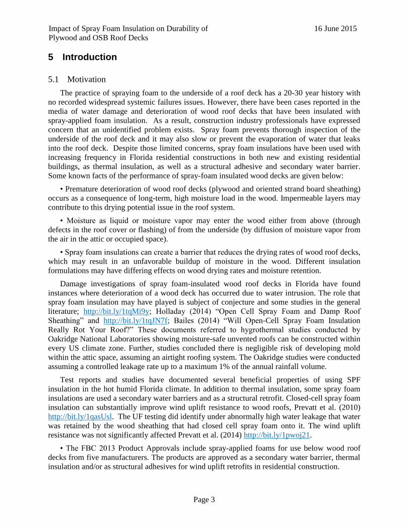
Unvented Cathedralized Attic – A structure that provides the same flat attic floor that is
characteristic of a conventional attic, however, the underside of the roof deck and the inside of
the gables are insulated and the attic space is never vented. Sometimes this configuration is
simply referred to by the more broad term of “unvented attic”.
Unvented Cathedralized Ceiling – A ceiling configuration in which the underside of the roof
deck is insulated and also forms the ceiling of the conditioned space. In this configuration there
is no attic space and no venting.
Vented Attic – An attic designed to allow airflow in and through the attic space. In vented
attics, typically the air, vapor and thermal controls are installed at the ceiling level. Vents at the
eaves, ridge and even along the slope of the roof deck provide the means of air infiltration and
exfiltration.
These attic configurations are illustrated in Figure 1.
Impact of Spray Foam Insulation on Durability of
Plywood and OSB Roof Decks
16 June 2015
Page 5
Figure 1: Illustration of common attic assemblies with different venting configurations.
Illustration from Schumaker (2007).

Impact of Spray Foam Insulation on Durability of
Plywood and OSB Roof Decks
16 June 2015
Page 6
6 Experimental Research Plan 1: Forming of Advisory Panel
An Advisory Panel of experts, researchers and construction professionals was convened to
advise the Research Team and to help identify information for the Literature Review. Panel
members came from Trade Associations representing roofing installers, engineering wood
materials, and manufacturers of roofing underlayment and of spray-applied foam insulation
products, in additional to contractors and consulting engineers (structural and mechanical).
Invitations were extended to researchers in Florida and elsewhere who have worked on unvented
attics and spray foam insulation issues in the past.
The input of the Advisory Panel was invaluable to present the latest information from their
respective organizations, as well as to vet the experimental research plans developed by the
Research Team. The compositions of the Advisory Panel is listed as follows:
NAME Company Representing
David Brandon Brandon Construction custom building, general contractor
John Broniek Icynene spray foam manufacturer
Paul Coats American Wood Council wood products representative
Bill Coulbourne Applied Technology Council engineering resources publisher
Rick Duncan, PhD SFPA spray polyurethane foam alliance
Mike Ennis SPRI single ply roofing institute
Mike Fischer Dir. Codes & Regulatory Affairs, Kellen asphalt roofing manufacturers
Jaime Gascon Miami/Dade Building Office building code official
Jason Hoerter NCFI spray foam manufacturer
Yuh Chin T. Huang, MD, MHS Pulmonary Medicine Specialist Duke University Medical Center
Scott Kriner Metal Construction Association Metal roofing association
Joseph Lstiburek, PhD Building Science Corporation building envelope consultant
Mo Mandani Florida Building Commission
Sean O’Brien Simpson Gumpertz & Heger Inc. building envelope consultants
Rick Olson Tile Roofing Institute producers clay & concrete tile roofing
Marcin Pazera, PhD Owens Corning Asphalt shingle roofing
Mike Petty Icynene spray foam manufacturer
Tim Reinhold, PhD IBHS insurance association
David Roodvoets, Building Envelope Consultant
Arlene Stewart Consultant Florida Homebuilders Association
Todd Wishneski BASF spray foam manufacturer
BJ Yeh, PhD Engineered Wood Association/APA Engineered wood industry
Mark Zehnal Florida Roofing & Sheet Metal Contractors Roofing professionals association
The Advisory Panel met twice during the project, once in Orlando, FL for the first in-person
meeting in 21/22 January 2015 and again by teleconference on 12 February 2015. The minutes
are attached in the Appendix B.

Impact of Spray Foam Insulation on Durability of
Plywood and OSB Roof Decks
16 June 2015
Page 7
7 Literature Review
The primary purpose of the building envelope is to protect the occupants of the building from
adverse elements. This includes providing a comfortable interior environment in which
conditioned air is kept inside, and moisture and ambient air is prevented from entering, all while
maintaining high air quality. Achieving this requires a thorough understanding of moisture and
air transport between the interior and exterior spaces, which occurs through the various building
materials we typically use to construct our buildings. While there is no single, exclusive
methodology for the design and construction of a proper building envelope, there are some
general rules for ensuring proper building envelope performance, which are summarized below
from Trechsel et al (2001) and illustrated further in Figure 2:
Install a vapor retarder on the inside of the insulation in cold climates,
Install a vapor retarder on the outside of the insulation in warm climates,
Prevent or reduce air infiltration,
Prevent or reduce rainwater leakage, and
Pressurize or depressurize the building so as to prevent warm, moist air from entering the
building envelope.
While these general rules provide basic guidelines that are appropriate for most
circumstances, they do not address all of the complexities associated with building envelope
design. One particular design choice that has generated a significant amount of research and
discussion is the choice of a vented or unvented attic space. Traditional wood-framed pitched
roofs have been constructed with fibrous batt insulation at the ceiling plane, with a large volume
above this insulation, typically referred to as the attic, well ventilated to the exterior air. However
in a move towards more energy efficient building envelope designs, there is a growing trend
towards insulating the sloped roof plane rather than the ceiling plane. This design results in the
entire building volume being insulated, which can increase the energy efficiency of the building
envelope by allowing the attic to contain HVAC systems, duct distribution, and also add
conditioned living or storage space. However the lack of ventilation in these roof assemblies
limits the capability of the roof system to transport infiltrating moisture, whether from interior or
exterior sources, away from components of the roof that are susceptible to decay, rot or fungus
growth with prolonged exposure to elevated moisture levels.

Impact of Spray Foam Insulation on Durability of
Plywood and OSB Roof Decks
16 June 2015
Page 8
Vapor diffusion retarder to the interior
Airflow retarder to the interior
Permeable exterior sheathing and permeable building
paper drainage plane
Ventilation provides air change (dilution) and also
limits the interior moisture levels.
Vapor diffusion retarder to the exterior
Airflow retarder to the exterior
Pressurization of conditioned space
Impermeable exterior sheathing also acts as drainage plane
Permeable interior wall finish
Interior conditioned space is maintained at a slight positive
air pressure with respect to the exterior to limit infiltration of
exterior, hot, humid air
Air conditioning also provides dehumidification (moisture
removal) from interior
Figure 2: Classic wall assemblies for cold climates (left) and hot-humid climates (right) from
Lstiburek (2002). The same principles mostly apply for roof assemblies.
This chapter summarizes the current knowledge on unvented and vented attics, specifically
related to moisture transport or lack thereof in roof systems with spray-applied polyurethane
foams. Section 1 briefly summarizes vented and unvented roof assemblies. Section 2 describes
spray-applied polyurethane foams and their use in unvented attics. Section 3 summarizes the
implications of moisture in wood materials. Section 4 describes and contextualizes recent
research into moisture issues in vented and unvented attics. Section 5 summarizes additional
research relevant to vented or unvented attics, spray foams or moisture transport in wood and
wood composite materials.
7.1 Vented and Unvented Attics
A vented attic is one in which there are means for consistent air flow through the attic space,
typically by allowing air to flow in through the soffits and exit through ridge or gable vents. In
vented attics, air, vapor and thermal barriers are installed at the ceiling level.
An unvented attics is one where the air, vapor and thermal barriers are installed at the roof
deck, causing the attic to become a conditioned space. No interior-to-exterior air flow is typically
allowed through the attic space.
The two types of attics are illustrated in Figure 3. When the ceiling is installed directly to the
roof slope framing, whether vented or unvented, the roof is further classified as a cathedral
ceiling.

Impact of Spray Foam Insulation on Durability of
Plywood and OSB Roof Decks
16 June 2015
Page 9
Figure 3: Illustration of vented (conventional) and unvented or cathedral attics, from Grin et al
(2010).
Hendron et al (2002) summarized the advantages and disadvantages of unvented attics, as
reproduced here in Table 1. While there are distinct advantages to an unvented attic, these can be
outweighed by the disadvantages if a systemic approach to the design of the complete building
envelope is not utilized. For example, in an unvented attic any moisture in the roof plane has
significantly less air volume to disperse into, which limits the capability of the wood framing and
decking to dry. Therefore specific care must be taken to handle any moisture accumulation in the
wood roof components.
Table 1: Potential advantages and disadvantages for unvented attics (Hendron et al. 2002)
Potential Advantages Potential Disadvantages
Milder environment for air ducts
Eliminates cost of installing vents
Semiconditioned storage area
Smaller latent load on air conditioner
(humid climates only)
Larger area for air leakage and heat
gain/loss
Additional cost for insulation
More difficult to install insulation at roof
plane compared to ceiling plane
Higher roof sheathing temperature
Higher shingle/tile temperature
Gas appliances (e.g., furnace, water
heater) located in attic must be closed-
combustion or be moved to garage.
7.2 Spray-applied Polyurethane Foams in Unvented Attics
Polyurethanes were originally developed in the late 1930s, and began to be used in a variety
of applications, including spray applications, in the post-World War II 1950s. Polyurethane spray
foams consists of two components, an A-side and a B-side, which must be mixed on site before
being sprayed onto the desired surface. The A-side is typically a mixture of approximately 50%
methylene diphenyl diisocyanate (MDI) and 50% polymeric methylene diphenyl diisocyanate

Impact of Spray Foam Insulation on Durability of
Plywood and OSB Roof Decks
16 June 2015
Page 10
(pMDI), two chemicals which are very reactive and therefore sensitive to improper mixing with
water or other compounds. The B-side is a blowing agent, primarily low-conductivity gases or
water, which boil from the heat of the exothermic reaction between it and the A-side chemicals.
This causes bubbles to form, and the curing of such bubbles determines the density of the foam.
Water-blown foams are typically low density, open cell foams. They are permeable to vapor
transmission and are non-structural, but have high resistance to air flow. Foams with low-
conductivity gasses as blowing agents, known as closed-cell foams, are typically much denser
than open cell foams. Wu et al investigated structure-property correlations in polyurethane rigid
foams based on effects of crosslink density, aromaticity, plasticizer and index. Specific focus
was given to the effect of the glass transition temperature, which typically defines the limits of
the service temperature, mechanical strength, stability and long term aging behavior. The study
demonstrated the importance of proper mixing and processing on the properties of SPFs.
Due to their high resistance to airflow and high R-values, spray-applied polyurethane foams
(SPFs) are commonly used in unvented attic applications. Closed cell spray-applied polyurethane
foams (ccSPF) have further uses as structural components, Datin et al (2010), and secondary
water barriers, Nelson and Der Ananian (2009), due to their denser composition and strong bond
to most structural substrates. However questions have arisen as to whether the presence of SPFs
on the underside of the roof decking will lead to elevated moisture contents and eventual rot and
decay of the roof structure. This is particularly a concern for ccSPF, which indeed can be
considered a secondary water barrier, Nelson and Der Ananian (2009). The value of a secondary
water barrier is apparent during a severe weather event, where the presence of a secondary water
barrier can prevent thousands of dollars in losses from moisture damage to interior contents.
Over the lifetime of a structure however, the same properties that make ccSPF a suitable
secondary water barrier can exacerbate moisture problems in wood roofs by limiting the drying
potential of roof assemblies that have had moisture enter the wood roof system.
There is a large body of existing research on various aspects of ocSPF and ccSPF in wood
attics. Moisture-related research is the focus of Section 4 of this chapter. Thermal and structural
performance of SPFs is not the focus of this project, but it is useful to summarize a few such
studies to demonstrate the potential benefits of SPFs.
Shreyans (2011) monitored the thermal performance of closed cell spray foam insulation
(ccSPF) installed in the roof deck of a vented, 1970s home in Gainesville FL. It was shown that a
1 in. layer of ccSPF was sufficient to reduce mean temperatures in a ventilated attic from 124°F
to 105°F. This attic temperature reduction also had positive benefits to energy consumption
required for the cooling load in the home, with daily energy consumption being reduced by 26%
after ccSPF was installed in the attic. No significant differences were noted in RH in the attic
before and after the ccSPF installation, but this is somewhat expected since the attic remained
ventilated even after the ccSPF installation. The results were able to be matched by simulations
of the thermal performance using the WUFI Pro 4.2 hygrothermal model.
Datin et al (2010) evaluated the wind-uplift capacity of ccSPF-retrofitted wood roof
structures and compared the results to standard construction methods using nails only. ccSPF
was installed ether as fillets between the truss framing and roof sheathing or in continuous layers
across the entire cavity between the top chord of the roof trusses and the roof sheathing. The
results demonstrated that ccSPF retrofits increased the wind resistance of pre-1994, Florida code-
minimum roof panels by as much as 300%. The findings suggest ccSPF is a strong retrofit choice

Impact of Spray Foam Insulation on Durability of
Plywood and OSB Roof Decks
16 June 2015
Page 11
for the more than 60% of existing residential inventory that may be susceptible to wind-uplift
failures. Prevatt et al (2014) followed up on this study by investigating the wind-uplift capacity
of ccSPF-retrofitted wood sheathing panels that been exposed to an extreme leakage scenario.
Despite the accumulation of significant amounts of moisture (moisture contents over 70%,
sheathing visibly saturated in some locations), no significant effects on the wind-uplift capacity
of the panels was observed.
7.3 Moisture Impacts on Wood Roofs
Moisture in wood roof systems typically arises from two main sources (Lstiburek 2002): (1)
liquid flow, e.g., rainwater, and (2) air transport and vapor diffusion. Each of these mechanisms
is capable of causing moisture-related building problems. Moisture arising from liquid flow
requires a physical breach in the building envelope, either due to a design flaw, physical damage
or an unusual loading scenario (e.g., wind-driven rain from a hurricane). Vapor diffusion is more
subtle, and varies by climate. In warm, humid climates, known as cooling climates, the warm air
at the exterior of the building envelope is driven towards the cooler, drier air of the conditioned
interior. In cold climates, known as heating climates, the warm, moist air is typically within the
interior of the building envelope and is driven towards the cold, dry air outside the building
envelope. As a result, in cooling climates, condensation tends to form on the exterior surface of
the insulation, which is at the sheathing/insulation interface in an unvented attic. The opposite is
true for heating climates, with condensation tending to form on the underside of the insulation. In
intermediate climates, or during seasonal changes, the direction of the vapor diffusion can be
more difficult to ascertain. The importance of the climate zones on building envelope strategy is
well-recognized in the existing literature. The United States has been divided into 7 different
climate zones, as shown in Figure 4from the US Department of Energy.

Impact of Spray Foam Insulation on Durability of
Plywood and OSB Roof Decks
16 June 2015
Page 12
Figure 4: International Energy Conservation Code (IECC) Climate Regions (DOE, 2013).
Lstiburek (2002) identified three strategies for controlling moisture in buildings:
5) Control of moisture entry;
6) Control of moisture accumulation;
7) Removal of moisture.
Vented attics employ the third strategy as the airflow through the attic space is efficient at
transporting incumbent moisture out of the roof system if designed properly. Unvented attics
often utilize the first strategy, using moisture and/or vapor retarders to prevent moisture from
entering the system. However, roof systems that are the most effective at keeping moisture out
are also conversely the least effective at controlling moisture accumulation if moisture does enter
the system (Pallin et al. 2013; Lstiburek, 2002).
Rose (1998) recommended an air chute which would provide an air gap between the
sheathing and the top of the insulation in unvented attics, allowing ventilation to carry the
moisture out of the roof system. Prevatt et al (2013) demonstrated potential with this approach in
a full-scale experiment as described in Section 3.4. However, more recent research has included
recommendations for sealing wood components at both the interior and exterior boundaries, with
the objective of preventing any moisture intrusion at all (Rudd 2005); Pallin et al. 2013).

Impact of Spray Foam Insulation on Durability of
Plywood and OSB Roof Decks
16 June 2015
Page 13
While the ultimate objective is to prevent moisture infiltration entirely, wood does provide a
hygric buffer (i.e., moisture storage) capacity of 40-50 gallons in a typical home (Lstiburek,
2002). However if wood is exposed to elevated moisture contents for prolonged periods of time,
it becomes susceptible to decay, rot and the growth of mold. Viitanen (1997) found that the
brown rot decay fungus requires a moisture content (MC) of 25-28% for growth. At these MCs,
growth could be activated at a temperature as low as 5°C after several months of exposure, with
more rapid growth as temperatures increase. These MCs can be achieved from equilibrium with
air at relative humidity of 94-96%. The threshold for safe relative humidity to which wood can
be exposed is typically taken as 80%, which gives an equilibrium moisture content in the wood
of 16% (Carll and Wiedenhoeft 2009; Lstiburek 2002; Saber et al. 2010). The general rule for
wood protection in construction is to keep moisture contents below 20%, as no fungi can grow
below 20% moisture content. Between 20% and 30% (generally taken as fiber saturation point),
fungi growth is possible in locally saturated fiber. Above fiber saturation, and with temperatures
between 10 and 40°C, conditions are well suited for fungi growth (Derome and Fazio 2000;
Griffin 1977).
Of particular importance to this project is the moisture performance of plywood and OSB
sheathing, which account for the vast majority of all structural wood panels in the US. Figure 5e
shows the vapor permeance (a measure of a material’s ability to permit moisture transport
through the material) for plywood and OSB as compared to two common vapor retarders. While
the water vapor permeance for both plywood and OSB increase with relative humidity, the
permeance of plywood is higher than OSB, particularly at higher relative humidities. This would
suggest that plywood is able to dry more quickly than OSB, a finding also noted by other studies
(Ojanen and Ahonen 2005; Wu et al. 2008)). With respect to surface moisture absorption,
plywood tends to absorb more moisture than OSB under equivalent circumstances. Ojanen and
Ahonen (2001) found that plywood products absorbed water faster than OSB during the first four
days of exposure, but slowed after this initial period. Water absorption into OSB started slow but
increased significantly after 1-2 weeks, and moisture levels in OSB exceeded those of plywood
after 2-3 weeks. The likely cause of these results is the differences in water repellence of the two
materials. OSB typically has water-repellant surface coatings that limit the absorption and drying
efficiency initially. Timusk (2008) found that cyclic wetting/drying had a large effect on
permeability of OSB, with permeability doubling after just one cycle. This was also noted by
(Nofal and Kumaran 2003). Wu and Ren (2000) however, noted that under long-term RH cycles
(12 month initial cycle followed by two 6 month cycles), the actual equilibrium moisture content
did not change significantly from one cycle to another.

Impact of Spray Foam Insulation on Durability of
Plywood and OSB Roof Decks
16 June 2015
Page 14
Figure 5: Water vapor permeance for building materials as a function of relative humidity
(APA, 2009).
In summary, while plywood and OSB are both common structural sheathing options, they do
have different hygric properties that may make one option more suitable for certain applications.
Therefore, different results can be anticipated for moisture related studies using both plywood
and OSB.
7.4 Impacts of Moisture in Vented and Unvented Attics
Derome et al (2010) used a large-scale environmental chamber to evaluate the risk of
moisture accumulation in single cavity, flat roof models fully insulated with cellulose fiber. The
roof structure consisted of 45 mm by 150 mm wood joists, covered by 19 mm by 150 mm wood
planks overlaid with a self-adhesive modified bituminous membrane. Moisture load was
simulated through varying the exterior relative humidity. The test sought to establish the
implications of moisture diffusion only (little or no air leakage) and air exfiltration together with
moisture diffusion on the wood roof assemblies. Moisture contents in the wood roof assemblies
were monitored using a combination of resistance-based moisture sensors and gravimetric
samples. With little or no air-leakage, moisture contents remained below 16% throughout the
year-long test period. With air leakage and moisture diffusion effects, moisture contents steadily
rose during the 90 day wetting period (RH between 65% and 71%), reaching as high as 35%,
before slowly falling during the 100 day drying period to around 10%. Ultimately, while
moisture contents rose and fell during the wetting and drying periods, there was no carryover of
moisture from one cycle to another, limiting the potential for wood rot and decay.
Prevatt et al (2014) exposed five full-scale wood roof specimens to 90 days of simulated and
natural rainfall in a Florida climate to evaluate moisture accumulation in closed cell spray-
applied polyurethane roofs. Test specimens consisted of 9.1 m (30 ft) by 3 m (10 ft) gable roof
“attics” with a roof slope of 26° (6 in 12), oriented north-south. All specimens were constructed
using wood trusses and 11.1 mm (7/16 inch) thick OSB decking. The roof system consisted of
30# felt and asphalt shingles, as shown in Table 2. Moisture contents in the wood trusses,
temperature and relative humidity were monitored throughout the duration of the exposure

Impact of Spray Foam Insulation on Durability of
Plywood and OSB Roof Decks
16 June 2015
Page 15
period using sensors and proprietary software from SMT Research. Details of the complete test
setup and scope are available in McBride (2011).
Table 2: Test matrix for full-scale roof specimens in Prevatt et al (2014).
Roof 1 Roof 2 Roof 3 Roof 4 Roof 5
No ccSPF
25 mm continuous
layer ccSPF
+ 75 mm fillet
25 mm continuous
layer ccSPF
+ 75 mm fillet
75 mm
continuous layer
ccSPF
75 mm
continuous layer
ccSPF
(104) 13-mm
leak gaps
(104) 13-mm
leak gaps No Leaks
(104) 13-mm
leak gaps No Leaks
After the exposure period, the roofing system was removed, revealing significant moisture
buildup in the roof specimens with leaks and ccSPF, primarily on the south facing roof slope. No
moisture buildup was observed in the specimen without ccSPF or those without leaks. Moisture
contents in the framing of the specimens with ccSPF and leaks reached as high as 70%. The
presence of the moisture did not significantly affect wind uplift capacities of the sheathing
panels. The tests demonstrated that for a worst-case leakage scenario, ccSPF inhibited the ability
of the roof system to dry. Without ccSPF, a roof under the same worst-case leakage scenario was
able to dry, preventing any moisture accumulation.
A subsequent study by Prevatt et al (2013), built on the results from the Prevatt et al (2014)
study to evaluate potential differences between OSB and plywood on moisture accumulation and
retention in ccSPF-retrofitted wood roofs. The study also evaluated the performance of two
moisture mitigation methods – (1) the use of a self-adhered membrane on the top surface of the
sheathing, taking the moisture control approach laid out by Lstiburek (2002); and (2) the
presence of an air gap between the ccSPF and the sheathing for 2/3rds of the capacity width,
leaving the full fillet to retain the structural benefits. This approach follows the recommendation
of Rose (1996). Four full-scale monoslope attic specimens were constructed and oriented so that
the slope faced south, based on the findings from Prevatt et al (2014) that moisture accumulation
was significantly higher on the south slope. Specimens were exposed to natural and simulated
rainfall for approximately 9 months, and leaks were deliberately cut into the roof covering to
allow moisture intrusion into the roof sheathing. Results demonstrated that self-adhered
underlayment on the top surface of the roof sheathing was effective at limiting moisture
accumulation in both OSB and plywood panels, with moisture contents greater than 20% only
observed locally at the locations of leak gaps. The air gap allowed the sheathing to dry
approximately twice as fast as sheathing without the air gap. The authors also noted that moisture
was absorbed more readily into the plywood panels, in agreement with previous research
(Ojanen and Ahonen, 2005; Wu et al, 2008).
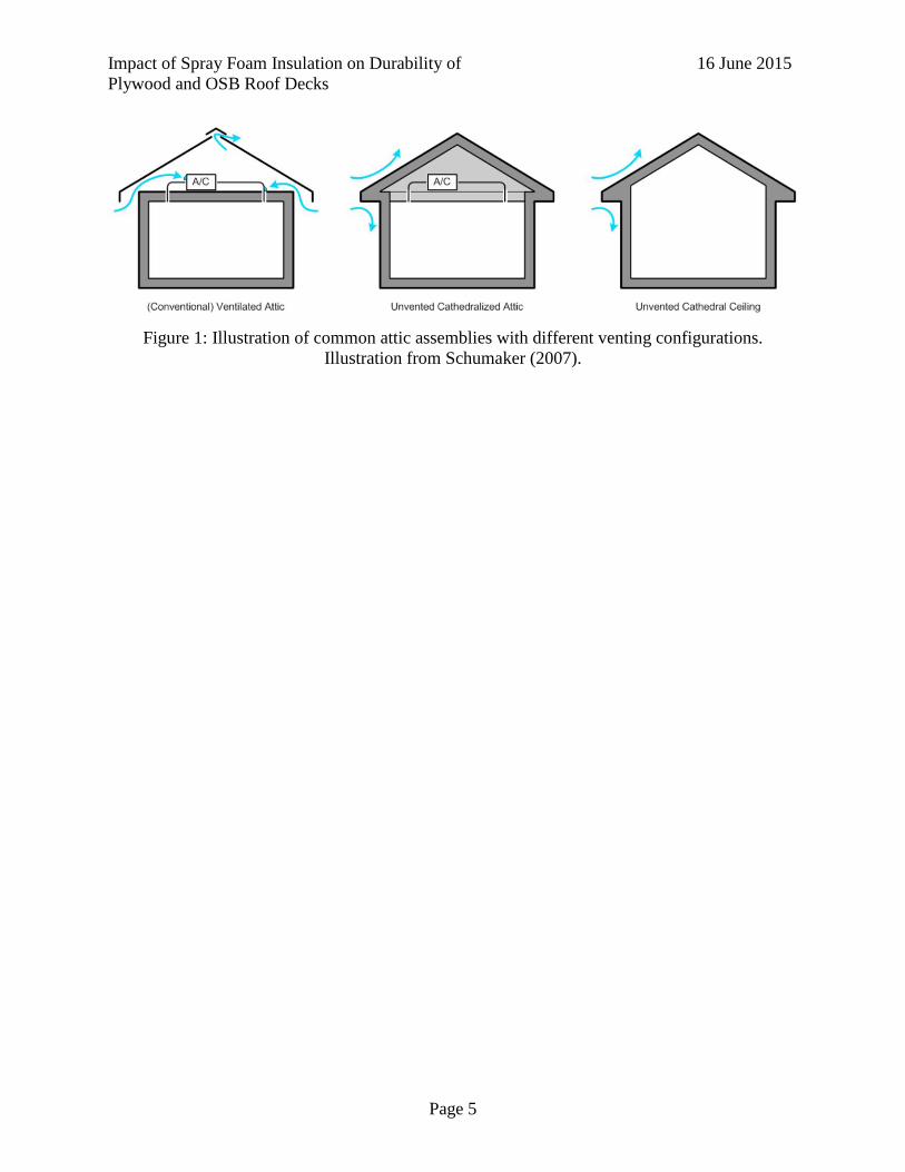
Prevatt et al (2013) also used bench top testing to quantify drying rates of plywood and OSB
samples both with and without ccSPF in a conditioned environment. Samples measuring 6 inch
by 6 inch by ½-inch thick were exposed to a continuous drip of water at a nominal rate of 1
Impact of Spray Foam Insulation on Durability of
Plywood and OSB Roof Decks
16 June 2015
Page 16
mL/min over a 24-hr period, and then allowed to dry in the conditioned environment. The edges
of the wood samples were sealed with a water sealant to restrict moisture transport through the
samples to 1-dimension. Results showed that for a 2:12 roof slope, plywood and OSB samples
with ccSPF dried 61% and 40% slower respectively than samples without ccSPF. For samples
elevated to match a 6:12 roof slope, plywood and OSB with ccSPF dried 51% and 65% slower
respectively. The half-life, based upon the exponential fit to the drying data, for each sample type
is given in Table 3.
Table 3: Drying rates (half-life in hours) for OSB and plywood samples with and without ccSPF
from Prevatt et al (2013)
OSB w/
ccSPF
OSB w/o
ccSPF
Plywood w/
ccSPF
Plywood w/o
ccSPF
2:12 Roof
Slope 72.7 51.5 61.5 38.1
6:12 Roof
Slope 91.2 55.3 72.0 47.8
Shreyans (2010) used a 1D WUFI Pro 4.2 hygrothermal model to simulate the drying times
of twelve different roof configurations. The evaluated parameters included the use of plywood
versus OSB, vented versus unvented attic space, and no spray foam, 1 inch ccSPF, and 3 inch
ccSPF. Roof performance was modeled over a ten year period, with an incidental leakage event
simulated in the summer of the third year. The simulated leakage had a leakage rate of 0.038
in/hr for a duration of eight hours. Exterior climate conditions were taken from recorded climate
data in Gainesville, FL (Climate Zone 2). Interior conditions were set at a temperature of 70°F
with a relative humidity of 35% +/- 15%. The results demonstrated that after the leakage was
event, moisture contents in the twelve roof configurations varied between 15% (unvented OSB
without ccSPF) and 63% (vented plywood with 3 inch ccSPF). Drying times were quantified as
the amount of time necessary for the roof system to return below 80% RH after the introduction
of the leak. Drying times varied from as little as 3 months to as much as 7 years. The shortest
drying time was found in the unvented OSB roof without ccSPF, followed closely by the
plywood roof of the same configuration, whether vented or unvented. The longest drying time
was found in the unvented OSB roof with 3 inch ccSPF, followed closely by the plywood roof of
the same configuration.
Saber et al (2010) exposed four full-scale wood wall assemblies to high sheathing moisture
contents and continuously monitored the drying rate over time. The 2.44 m by 2.44 m (8 ft by 8
ft) wood wall assemblies consisted of wood stud framing with glass fiber insulation filling the
stud cavities, 11.5 mm (7/16 inch) OSB sheathing, 6-mil polyethelene vapor barrier on the
interior of the wall assembly. A polyolefin sheathing membrane was installed on the outer
surface of the OSB in one wall assembly, while two other assemblies had asphalt impregnated
building paper installed on the exterior OSB surface, with one also having gypsum installed on
the interior of the assembly. The last wall assembly did not have a sheathing membrane installed.
Sheathing moisture contents for all wall assemblies were above 35% at the start of the drying
period, and the assemblies were continuously weighed to monitor the loss of moisture with time.
The physical drying rates were compared with a hygrothermal model, known as hygIRC-C,
which solved the coupled 2D and 3D Heat, Air and Moisture transport equations in porous
median and non-porous media.

Impact of Spray Foam Insulation on Durability of
Plywood and OSB Roof Decks
16 June 2015
Page 17
Without any sheathing membrane, the moisture in the wall assembly had a half-life of 480
hours. With the polyolefin sheathing membrane, the drying rate was significantly slower, with
moisture contents only reducing from 51% to 35% during 384 hours of drying. The wall
assembly with asphalt impregnated sheathing membrane but no gypsum had an initial moisture
content of 70%, which was reduced by half in 385 hours. The wall assembly with gypsum
installed had an initial moisture content of 37%, but dried very slowly, reducing to 28% MC in
576 hours. The results demonstrated that drying rates in OSB sheathing are significantly affected
by the components of the wall assembly, particularly the use of vapor barriers. The physical and
numerical results agreed well for all wall assemblies, with errors remaining within +/- 5%.
Salonvaara et al. (2013) investigated the moisture performance of sealed (i.e., unvented)
attics compared to vented attics in order to understand the risks of high moisture content in the
roof sheathing and high humidity in the attic. Open-cell spray foams were simulated in the
unvented attic. To compare effects of vapor permeability, spray foam permeances of 23 perm-in
(33.58 ng/smPa) and 54 perm-in (78.84 ng/smPa) were used. The vented attic was simulated
with blown fiberglass insulation on the ceiling deck. The simulation was conducted in four
different cities in four different climate zones - Miami, FL; New Orleans, LA; Atlanta, GA; and
Baltimore, MD. The moisture performance of the attic was simulated in two ways: first the roof
sheathing moisture content was analyzed with a building enclosure simulation model, and second
the attic humidity was investigated using a whole house simulation model. Moisture loads were
developed to represent two cases – (1) vapor pressure resulting from interior moisture load of 4
g/m3 (0.00025 lb/ft3), based upon assumed moisture production and ventilation rates, and (2)
same conditions as (1) plus rain intrusion into the wood roof sheathing amounting to 1% of local
rainfall totals. The models used for the moisture analysis were WUFI-Pro and WUFI-Plus. The
models were calibrated against measured attic humidity and temperature data in a Tennessee
home from Oak Ridge Lab. Results of the study demonstrated that the vented attic performed
well with moisture contents remaining below 15% in the roof sheathing with or without the rain
intrusion. Even with 1% water intrusion, the moisture content of the OSB stayed below 15% by
weight at all times in all the four climate zones. The moisture content levels in the unvented attic
were generally higher than in the vented attic. Without rain intrusion, moisture contents
remained below 20%. With 1% rain intrusion, moisture contents in all but Climate Zone 1
(Miami, FL) were above 20%, with Climate Zone 4 (Baltimore, MD) having the highest
moisture contents (30%) and the most prolonged exposure to moisture contents above 20%.
Moisture contents increased with increasing permeance of the spray foam for all but Climate
Zone 1 (Miami, FL).
Pallin et al. (2013) performed a hygrothermal risk analysis for unvented residential attics
hosting an HVAC system to determine the critical parameters in the development of wood rot
and mold. The hygrothermal model included two main components:
1) A WUFI 1D model, which predicts moisture transport through a single axis. Two models
were used to simulate the north and south faces.
2) A custom MATLAB model to model the radiative heat exchange in intermediate air
spaces or surfaces, and is not capable of calculating indoor boundary conditions.
Key input parameters to the hygrothermal models included indoor heat and moisture
production, hygrothermal material properties, air leakage, outdoor climate, orientation and
location of the building and roof slopes, features of the HVAC system, and user behavior, i.e.,

Impact of Spray Foam Insulation on Durability of
Plywood and OSB Roof Decks
16 June 2015
Page 18
HVAC setpoint temperatures, maintenance, etc. In the study, 224 different compositions were
simulated for an unvented attic, with the varied parameters consisting of the thermostat setpoint,
outdoor climate, vapor permeance of the spray foam, air leakage rates of the ventilation,
airtightness of the ceiling floor, and the indoor moisture production. Outcomes for each
composition consisted of three different performance indicators: (1) the maximum moisture
content of the OSB sheathing, (2) the HVAC system energy demand, and (3) the mold growth
index of the wood-based materials in the attic space. The simulated roof was assumed to have
OSB sheathing (no thickness specified), asphalt shingles, and spray-applied polyurethane foam
(SPF), both closed-cell and open-cell. Seven different climates (locations) were simulated.
Moisture contents were simulated over a 1 year period.
Moisture contents started at 16% and varied between 13% and 55% between all of the
models over the simulated year. The models with the highest ending moisture contents for all 7
climate locations were north-facing open-cell models, with moisture contents between 37% and
54%. The lowest ending moisture contents were observed in closed-cell, south-facing roofs, with
moisture contents never exceeding 14%. The most important parameters to the OSB moisture
content identified in the model were the vapor permeance of the SPF (higher was better), the
climate conditions (although no trends are stated related to climate and moisture), and the indoor
moisture production (higher moisture production increased risk). The climate with the highest
moisture ending moisture contents was Baltimore, MD.
Nelson and Der Ananian (2009) used the WUFI hygrothermal software to compare moisture
drying rates of vented and unvented roof assemblies. The models varied by insulation type
(glass-fiber batt, open-cell SPF, closed-cell SPF), sheathing type (plywood or OSB) and weather-
resistant barrier type (felt or self-adhered rubberized asphalt membrane [SRAM]). They
conducted 1D moisture movement studies and predicted the moisture build-up that would in
occur in wood following introduction of a leak and subsequent years of thermal cycling. Their
study simulated conditions in Miami, FL and Boston, MA over a ten year period. A single leak
was introduced, simulating a wind-driven rain storm, with a leakage rate of 976.5 g water/m2h
(0.20 lb water/ft2hr) for eight hours in the third summer of each simulation. Moisture was
quantified by %RH in the wood sheathing and gypsum, with 80% RH taken as the threshold for
initiation of decay. Results showed that unvented roof assemblies with ccSPF (perm rate = 0.17
perms) had the slowest drying potential, requiring a minimum of 7 months for sheathing to dry
with felt underlayment and a minimum of 12 months with SRAM. Open-cell SPF and glass-fiber
batt insulation roof assemblies, whether vented or unvented, performed significantly better with
drying times of 2 months or less. In the Boston, MA climate, unvented ccSPF roof assemblies
were again the slowest to dry, requiring 14 months to dry with felt and at least 26 months with
SRAM. Vented ccSPF roof assemblies were able to dry in 2 months, similarly too all other roof
assemblies considered. In both the hot and cold climates, drying times for OSB and plywood in
all roof assemblies differed by a month or less.
Grin et al (2013) conducted hygrothermal modeling using WUFI 5 software on roof
assemblies located in hot, rainy climates (Miami), cold climates (Minneapolis) and a rainy,
marine climate (Seattle). Roof assemblies were modeled on the north orientation only with
parameters as given in Table 4 from exterior to interior. Leakage rates were based on ASHRAE
160 (ASHRAE 2008) recommendations for wall design leakage rates, given as 1% of the water
reaching the surface. A 4 ft2 area near the ridge of a 6/12 pitch roof was chosen for the leakage
calculations, which, based on US Climate Normals data, gives 1% of annual rainfall as 1 gallon/4

Impact of Spray Foam Insulation on Durability of
Plywood and OSB Roof Decks
16 June 2015
Page 19
ft2 (2.6 L/4 ft2), 2 gallon/4 ft2 (7.9 L/4 ft2), and 1 gallon/4 ft2 (4.2 L/4 ft2) for Minneapolis, Miami
and Seattle respectively.
Table 4: Basic Modeled Roof Assemblies in Grin et al (2013)
Minneapolis
Roof A
Minneapolis
Roof B
Miami and Seattle
Roof A
Miami and Seattle
Roof B
Exterior air Exterior air Exterior air Exterior air
Asphalt shingles Asphalt shingles Asphalt shingles Asphalt shingles
½-in plywood or
OSB structural roof
sheathing
½-in plywood or
OSB structural roof
sheathing
½-in OSB structural
roof sheathing
½-in OSB structural
roof sheathing
R-25 ccSPF R-25 ocSPF + 5 perm R-12 ccSPF R-30 ocSPF
R-24 fibrous air and
vapor permeable
insulation
R-24 fibrous air and
vapor permeable
insulation
R-19 fibrous air and
vapor permeable
insulation
Interior air Interior air Interior air Interior air
The modeling results demonstrated that all of the roof assemblies modeled exhibited drying
capacity to handle minor rainwater leakage. The authors state that “the 2012 IRC-compliant
roofing system in Minneapolis using ccSPF on plywood sheathing with cellulose insulation on
the interior has the capability according to the modeling to safely dry 53 oz (1.6 L) of water
through a 4-ft2 area of plywood per year. MCs > 20% were seen during the modeling, but the
systems were typically able to dry during the summer and return to < 8% MC. Within the Seattle
analysis the ccSPF insulated OSB-sheathed roofs were able to handle up to 1% rainwater
leakage, while the ocSPF roof experienced elevated MC when more than 0.6% rainwater leakage
was introduced into the system. This is due to both rainwater leakage and outward vapor drives
during the heating season. The ocSPF roofs dried out much more readily than the ccSPF roofs.
The Miami analysis showed that that both ccSPF and ocSPF roofs dried, even up to 1.5%
rainwater leakage, although both experienced more short-term fluctuation than similar roofs in
the Seattle climate”. In general, the ocSPF dried more readily than ccSPF. Orientation and
sheathing materials had relatively small impacts on drying capabilities in comparison to the type
of SPF and vapor permeance coatings used.
Prahl et al (2014) used computational fluid dynamics and a 2D hygrothermal model to
evaluate the moisture risk in unvented attics with ccSPF insulation due to air leakage paths from
the unvented attic space to the exterior. The analysis was particularly focused on airflow paths
from plumbing penetrations, spray foam delamination, framing intersections, and ridge vent
sealing. The modeled roof system was based upon an actual 2,000 ft2 home in Minneapolis, MN,
which had an unvented attics with OSB sheathing, ccSPF (depth or permeance not given) and
shingles and other roofing materials, although only the OSB and ccSPF were modeled in this
study. Results showed that low airflow rates (less than 2.5 CFM at 4 Pa) resulted in moisture
contents above 20% in the surrounding sheathing, localized to an area 5 inches from the crack,
for most of the winter and spring in cold climates. However in all cases the accumulated
moisture was able to dry during the full annual cycle.
Straube et al (2010) used the WUFI Pro 4.0 hygrothermal model to evaluate the moisture
performance of unvented, cathedralized-attic wood roofs. The influences of roofing materials,

Impact of Spray Foam Insulation on Durability of
Plywood and OSB Roof Decks
16 June 2015
Page 20
interior environments and climate zones were the primary considerations of this study. Several
different insulation products, including fibrous and foam insulations, were included in the study.
The modeled roofs had 3:12 roof slopes and were oriented to the north, considered the worst-
case scenario for colder climates. Local weather data for each location was used for the exterior
conditions of the model. Interior conditions were varied from medium to high interior moisture
levels, based on EuroNorm Standard 15026 (Euronorm 2007). The study identified the most
important factor as the control of airflow through the insulation itself. The worst moisture
performances were typically linked to poor airflow control. Full-depth ccSPF resulted in
moisture contents below 16% all year for all 7 US climate zones. Full-depth ocSPF performed
well in warm or mild climate zones, but resulted in prolonged exposure to moisture contents
above 16% in cooler climate zones.
Alturkistani et al. (2008) developed a standardized test method for evaluating building
envelope drying capacity and demonstrated it using thirty-one wall assemblies. The different
configurations were obtained by varying the interior finish (two different gypsum types),
sheathing type (OSB, fiberboard or plywood) and cladding system (wood siding on furring and
Tyvek, and cement stucco on metallic lath). The insulated core in all configurations was glass
fiber insulation. The moisture loading was provided using evaporation of water from containers
placed within the stud cavity of the walls at the bottom plate. The containers were not refilled
during the course of the experiment. The amount of evaporated moisture was measured
continuously using load cells under the water containers. Moisture contents in the wood wall
components (2x6 studs and sheathing) were monitored weekly using gravimetric samples that
were removed, weighed and reinstalled. The drying capacity of different building envelopes was
quantified using the Drying by Evaporation Index (DEI), which was used as a measure of the
rate of moisture movement out of the stud cavity. The wall configurations with fiberboard
sheathing demonstrated the highest drying capacity (maximum of 99%), followed by plywood
(maximum of 89%) and then OSB (maximum of 82%).
As can be seen with the number of reviews above, there is a significant body of work
assessing the thermal and moisture performance of vented and unvented attics with SPF for a
variety of climates. Table 5 summarizes the “best” and “worst” roof configurations from the
various studies, with the assessments based upon the ability of the roof configuration to remain
below 16%, the typically assumed threshold for acceptable moisture levels in wood members.
In general, the multiple studies available in the published literature demonstrate good
agreement, so long as the assumptions and limitations of each study are taken into account.
Studies which investigated moisture loads from interior or exterior humidity sources only
generally were in agreement that ccSPF was effective at preventing any moisture accumulation
to unsafe levels. However, studies which incorporate leakage generally found that ccSPF was the
least effective at controlling moisture contents, while vented roof assemblies or ocSPF generally
performed better. Warm climates generally provided a better drying environment than cold
climates. No significant differences between plywood and OSB were observed in most numerical
models, although the physical experiments did tend to demonstrate differences in performance
by sheathing type (Prevatt et al, 2013; Alturkistani et al, 2008). This is an important reminder
that many of the existing research conclusions are based upon numerical models which are only
as good as the inputs and assumptions that are provided to them. As these models continue to
improve and include more complexity, it is possible that some conclusions may change. The

Impact of Spray Foam Insulation on Durability of
Plywood and OSB Roof Decks
16 June 2015
Page 21
importance of comparisons of the models to physical experimental results or field studies cannot
be overstated.
The body of literature available today on this subject matter demonstrates the fact that there
is no one-size-fits-all building envelope solution for all configurations and all climates. There are
design choices that can be made that will allow nearly any configuration (e.g., vented or
unvented, ccSPF or ocSPF or fibrous insulation, etc) to perform adequately, so long as the design
of the system is approached holistically with a thorough understanding of building envelope
science.
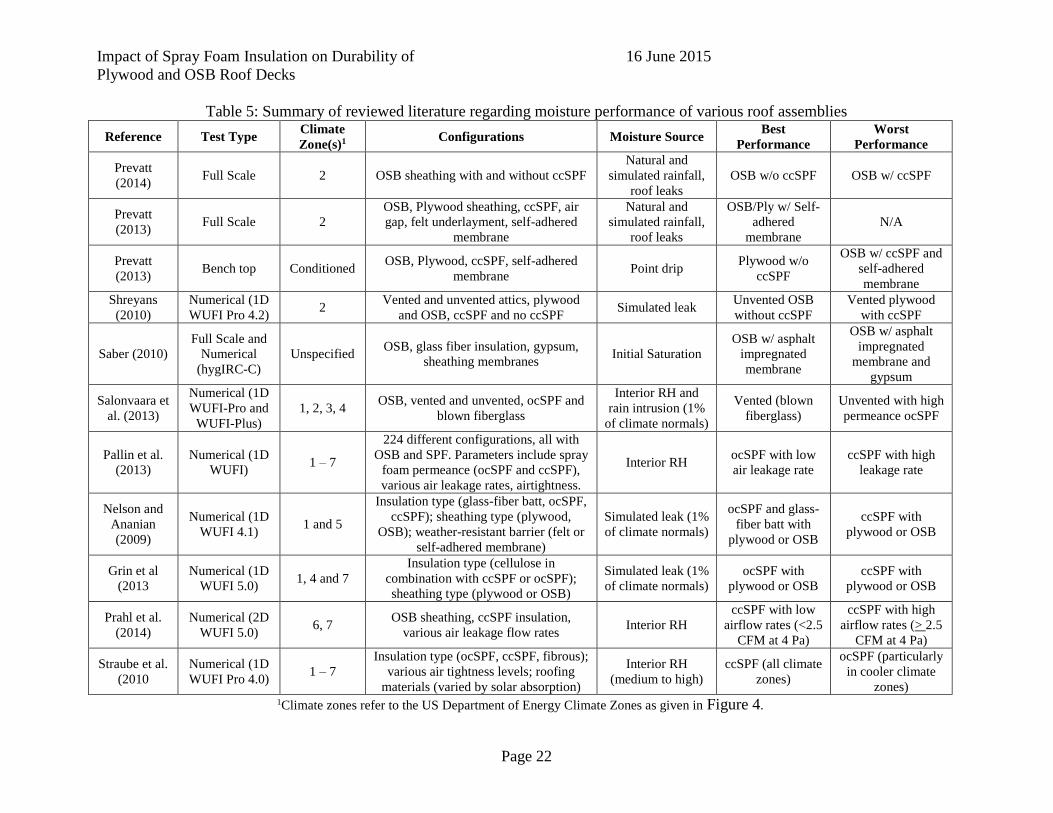
Impact of Spray Foam Insulation on Durability of
Plywood and OSB Roof Decks
16 June 2015
Page 22
Table 5: Summary of reviewed literature regarding moisture performance of various roof assemblies
Reference Test Type Climate
Zone(s)1 Configurations Moisture Source
Best
Performance
Worst
Performance
Prevatt
(2014) Full Scale 2 OSB sheathing with and without ccSPF
Natural and
simulated rainfall,
roof leaks
OSB w/o ccSPF OSB w/ ccSPF
Prevatt
(2013) Full Scale 2
OSB, Plywood sheathing, ccSPF, air
gap, felt underlayment, self-adhered
membrane
Natural and
simulated rainfall,
roof leaks
OSB/Ply w/ Self-
adhered
membrane
N/A
Prevatt
(2013) Bench top Conditioned
OSB, Plywood, ccSPF, self-adhered
membrane Point drip
Plywood w/o
ccSPF
OSB w/ ccSPF and
self-adhered
membrane
Shreyans
(2010)
Numerical (1D
WUFI Pro 4.2) 2
Vented and unvented attics, plywood
and OSB, ccSPF and no ccSPF Simulated leak
Unvented OSB
without ccSPF
Vented plywood
with ccSPF
Saber (2010)
Full Scale and
Numerical
(hygIRC-C)
Unspecified OSB, glass fiber insulation, gypsum,
sheathing membranes Initial Saturation
OSB w/ asphalt
impregnated
membrane
OSB w/ asphalt
impregnated
membrane and
gypsum
Salonvaara et
al. (2013)
Numerical (1D
WUFI-Pro and
WUFI-Plus)
1, 2, 3, 4 OSB, vented and unvented, ocSPF and
blown fiberglass
Interior RH and
rain intrusion (1%
of climate normals)
Vented (blown
fiberglass)
Unvented with high
permeance ocSPF
Pallin et al.
(2013)
Numerical (1D
WUFI) 1 – 7
224 different configurations, all with
OSB and SPF. Parameters include spray
foam permeance (ocSPF and ccSPF),
various air leakage rates, airtightness.
Interior RH ocSPF with low
air leakage rate
ccSPF with high
leakage rate
Nelson and
Ananian
(2009)
Numerical (1D
WUFI 4.1) 1 and 5
Insulation type (glass-fiber batt, ocSPF,
ccSPF); sheathing type (plywood,
OSB); weather-resistant barrier (felt or
self-adhered membrane)
Simulated leak (1%
of climate normals)
ocSPF and glass-
fiber batt with
plywood or OSB
ccSPF with
plywood or OSB
Grin et al
(2013
Numerical (1D
WUFI 5.0) 1, 4 and 7
Insulation type (cellulose in
combination with ccSPF or ocSPF);
sheathing type (plywood or OSB)
Simulated leak (1%
of climate normals)
ocSPF with
plywood or OSB
ccSPF with
plywood or OSB
Prahl et al.
(2014)
Numerical (2D
WUFI 5.0) 6, 7
OSB sheathing, ccSPF insulation,
various air leakage flow rates Interior RH
ccSPF with low
airflow rates (<2.5
CFM at 4 Pa)
ccSPF with high
airflow rates (> 2.5
CFM at 4 Pa)
Straube et al.
(2010
Numerical (1D
WUFI Pro 4.0) 1 – 7
Insulation type (ocSPF, ccSPF, fibrous);
various air tightness levels; roofing
materials (varied by solar absorption)
Interior RH
(medium to high)
ccSPF (all climate
zones)
ocSPF (particularly
in cooler climate
zones) 1Climate zones refer to the US Department of Energy Climate Zones as given in Figure 4.

Impact of Spray Foam Insulation on Durability of
Plywood and OSB Roof Decks
16 June 2015
Page 23
7.5 Field Performance Reports for Spray Foam Insulated Roofs
In addition to the numerous numerical and physical research experiments regarding moisture
in unvented attics, it is paramount to also summarize any field investigations that are available.
These provide “real-world” performance of these roof systems and can serve to validate the
existing body of experimental work. There are a few such studies, which are summarized below.
Anecdotal evidence of moisture issues in SPF attic systems from various web sources and
personal communications is also included.
Rudd (2004) performed field investigations of six cold climate homes (located in Minnesota,
Wisconsin and Massachusetts) and five hot, humid climate homes (located in Texas and Florida)
to quantify the performance of unvented, cathedral attics. Four of the cold climate homes had
ocSPF with thicknesses varying between 3 and 9 inches, while one home had ccSPF of 3 inch
thickness. Roof sheathing consisted of plywood, OSB or wood planks, and all homes had asphalt
shingles. House and attic relative humidity was measured, along with attic temperatures.
Moisture contents of the sheathing and framing were measured using resistance-based moisture
meters. Attic relative humidity in the six homes were as low as 30% in some homes and more
than 85% in others. Sheathing moisture contents were between 6 and 7% in the home with
ocSPF, but were greater than 20% in all but one of the homes with ocSPF. In all homes, the
highest sheathing moisture contents were on nominally north-facing slopes. Framing moisture
contents ranged from 6% to 12% in all six homes. In the hot, humid climate homes, moisture
contents were only measured in two homes, both of which had open-cell, low density foam
insulation under plywood roof sheathing, creating a sealed (non-vented) attic. The roof covering
consisted of 15# building felt and asphalt shingles. Sheathing moisture contents ranged between
7 and 16% with a median of 10%. Framing moisture contents ranged from 7 to 12% with a
median of 9%. There were no signs of moisture condensation, mold, or delamination.
Boudreaux et al (2013) studied eight homes in a mixed-humid climate to investigate the
moisture performance of sealed attics. Four of the homes were unvented attics, the remaining
four were vented attics. Two of the unvented attics and one of the vented attics were unoccupied.
All homes had OSB roof sheathing with 15# felt paper and asphalt shingles. All had been
retrofitted in the months preceding the start of the monitoring period. Moisture levels were
quantified as the partial pressure of water vapor (Pa) over a 9 month period between January
2012 and September 2012. On average, the sealed attic homes had approximately 20-30% higher
attic and interior moisture levels as compared to the vented attic homes. Despite the higher attic
and interior moisture in the sealed attic, there was no indication of mold or material degradation.
Colon (2011) investigated the thermal and moisture performance of a home in Rockledge, FL
which was constructed in March 2010. The home featured a sealed attic with open cell spray
foam insulation, as shown in Figure 6. Temperature and relative humidity were monitored in the
conditioned space, attic and outdoors for a full year, between April 2010 and April 2011, at 15
minute intervals. The home was not occupied during the testing period, but the air conditioner
did operate. It was noted that the new home started an interior RH near 60%, which slowly
decreased towards the target of 50% over the course of 5 months. The author indicated that high
humidity content is common in new construction for the first year or two of use due to moisture
in building materials. In the sealed attic, relative humidity, measured 6 inches below the sprayed

Impact of Spray Foam Insulation on Durability of
Plywood and OSB Roof Decks
16 June 2015
Page 24
roof deck, reached as high as 83% in May 2010 and 78.3% in April 2011, but were as low as
45% during the winter months.
Figure 6: (Left) Front view of home showing conventional hip roof and shingles; and (right)
View of the open-cell spray foam insulation in the attic (Colon 2011)
Schumaker (2008) performed field investigations of multiple roofs to assess the
hygrothermal performance of insulated, sloped, wood-framed roof assemblies. The homes or test
facilities were located in Vancouver, BC, Ottawa, ON, and Coquitlam, BC in Canada and in
Atlanta, GA in the United States. The test hut in Coquitlam, BC contained two roof assemblies
with OSB sheathing, asphalt shingles and ocSPF insulation creating an unvented attic. Moisture
contents in the sheathing remained below 19% over the course of a year of monitoring. The
Vancouver, BC test house also utilized ocSPF to create an unvented attic. The home was
constructed just prior to the beginning of the monitoring period. Interior relative humidity
remained below 60% throughout a 27 month monitoring period. Moisture contents in the
sheathing during the initial months after monitoring began reached 25%, but in subsequent years,
moisture contents for the same month of the year were steadily lower, remaining less than 18%
in the last year. The high initial moisture contents appeared to be due to the moisture stored
within the construction materials.
7.6 Information Received on Moisture Damage to Roofs
The Advisory Panel was asked to provide any evidence of roof deterioration in spray foam
insulated roofs. We received the following photographic descriptions:
7.6.1 House 1
Mark Zehnal provided evidence of a damaged roof system in Palm Beach County that had
closed cell spray foam insulation installed. We were told that the home was built in 2005 and
was repaired in 2014. This series of photographs documents the extent of damage to the roof
deck and wood framing adjacent to a large dormer. The photos show a rotted deck adjacent to a
dormer . The photos did not identify the source of the water (although experience suggests failed
flashing below the window sill and or failed base flashing along the dormer wall are potential
sources).

Impact of Spray Foam Insulation on Durability of
Plywood and OSB Roof Decks
16 June 2015
Page 25
Figure 7: Moisture damage in an unvented attic with ccSPF. Moisture was particularly event
around the visible dormer (Courtesy of Mark Zehnal).
7.6.2 House 2
The roof system of a Palm Beach Gardens, FL house with spray applied insulation showed
signs of water intrusion damage. As seen in the photo the sheathing and wood framing both
began to rot and is speculated to be caused by the elevated moisture content of the sheathing due
to a leak caused by roof defection. As was seen in the first case this damage occurred next to a
window which suggests the moisture could have entered the system due to failed flashing at the
window sill and been trapped between the spray foam and the sheathing. A forensic study was
not conducted on this home so these photos are considered anecdotal and just an example of a
home with spray foam and moisture damage.
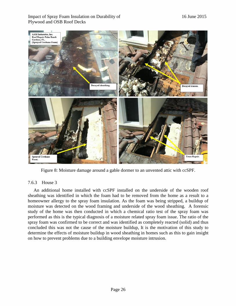
Impact of Spray Foam Insulation on Durability of
Plywood and OSB Roof Decks
16 June 2015
Page 26
Figure 8: Moisture damage around a gable dormer to an unvented attic with ccSPF.
7.6.3 House 3
An additional home installed with ccSPF installed on the underside of the wooden roof
sheathing was identified in which the foam had to be removed from the home as a result to a
homeowner allergy to the spray foam insulation. As the foam was being stripped, a buildup of
moisture was detected on the wood framing and underside of the wood sheathing. A forensic
study of the home was then conducted in which a chemical ratio test of the spray foam was
performed as this is the typical diagnosis of a moisture related spray foam issue. The ratio of the
spray foam was confirmed to be correct and was identified as completely reacted (solid) and thus
concluded this was not the cause of the moisture buildup, It is the motivation of this study to
determine the effects of moisture buildup in wood sheathing in homes such as this to gain insight
on how to prevent problems due to a building envelope moisture intrusion.

Impact of Spray Foam Insulation on Durability of
Plywood and OSB Roof Decks
16 June 2015
Page 27
Figure 9: Evidence of moisture buildup in home installed with ccSPF. Note the moisture on
both the sheathing and wood framing
7.7 Moisture in Foam Insulated Roofs and Health Effects
Mark Zehnal told the research team by email that one of his FRSA member contractors was
asked by the homeowner to remove the closed cell spray foam insulation that was installed
during the construction of an addition. The homeowner experienced allergic reactions after the
foam insulation was installed. The homeowner explained the occupants had no symptoms before
the foam was installed but they continued to experience allergy / illness after installation (no
length of time specified). The Contractor had foam samples tested, which indicated all chemicals
were mixed at “proper” ratios and they had completely reacted (in a solid form). Photographs of
the removal of the spray foam were presented earlier in Section 3.6.3. The Contractor reported to
Mark Zehnal as follows:
1. On examination, moisture was observed on the deck side of the foam insulation and
along the top chord of the wood trusses.
2. Foam samples showed signs of heat stress and moisture in direct contact with the 19/32”
CDX plywood, and the foam had a darker color near the wood deck as compared with the
underside (attic side) of the installation.

Impact of Spray Foam Insulation on Durability of
Plywood and OSB Roof Decks
16 June 2015
Page 28
By way of explanation, the Contractor wrote that vapor transmission (moisture) occurs at the
hottest time of day driving moisture into areas of lower vapor pressure (i.e. inside the attic). This
vapor transmission may be associated with moisture trapped in the roof sheathing and being
driven through the foam insulation into the attic (internal air flow). The Contractor hypothesized
that sealed attic systems have (unanticipated) air exchanges between attic and interior (occupied)
spaces, which may help maintain dehumidified conditions in the attic. However such air
exchange may also simultaneously draw off-gasses from newly installed foam insulation into the
occupied spaces, thus adversely affecting air quality.
The Contractor also described to Zehnal of a similar situation that was witnessed by his (the
Contractor’s) colleague. In that case a homeowner reported experiencing allergic reactions
following the installation of foam insulation (no type specified). The homeowner stated the
allergic reaction was highest during the hottest part of the day (midday and into afternoon). This
would coincide with the vapor transmission of the moisture from the roof side & deck being
driven into the attic cavity.
7.7.1 Health Effects Studies
While occupant health was not included in the original scope of this project, the above
information was brought to the attention of the research team and we shared this with the
Advisory Panel. Volatile organic compounds (VOCs) occur in many areas of the construction
industry and they are known to cause allergic reactions. The influence of VOCs on indoor air
quality is discussed by the Environmental Protection Agency (EPA 2012). Spray foam insulation
is one of dozens of construction materials that can produce VOCs. In addition, a fully sealed
attic may also create a tighter sealed building and indoor air quality can be diminished over time
if insufficient make-up air is provided. The literature reviewed below documented some
instances where occupants experienced adverse reactions following the installation of spray foam
insulation.
A recent EPA initiative has focused attention on identifying potentially harmful chemicals in
spray foam insulations (EPA 2015). This effort is conducted with the involvement of the major
spray foam insulation trade associations and some companies. The result has been a
strengthened protocol for safe handling, evacuation and re-occupation of premises before and
after the spray foam installation.
Spray foam insulations are comprised of two components; A-side and B-side that are mixed
together. The A-side consists of isocyanates, which the EPA website states can cause skin, eye
and lung irritation, and have been identified as the leading attributable chemical cause of work-
related asthma. The B-side of SPFs is usually a blend of chemicals, many of which are toxic. The
primary risk for exposure to these chemicals is during installation and curing, while the chemical
reaction is underway.
After SPF is applied and cured, it is typically considered relatively inert, meaning the
harmful chemicals do not continue to be released over time (EPA 2015). However, if occupants
are allowed re-entry into a building after SPF installation too soon, while the curing process is
still ongoing, or during demolition or disassembly, they can be exposed to toxic emissions from
the chemicals. The EPA recommends 24-hours after installation before re-entry without personal
protection equipment, but they mention that curing times are highly variable and that more

Impact of Spray Foam Insulation on Durability of
Plywood and OSB Roof Decks
16 June 2015
Page 29
research is needed. To address long-term concerns for exposure potential the EPA website
includes the following:
Maintenance workers, including plumbers and electricians, should not heat or grind
spray foam. Spray foam can potentially generate toxic emissions under these
circumstances.
Building renovations, demolition, or building disassembly done years later can disturb
spray foam insulation. Performing hot work on or near polyurethane foam may lead to
potential exposures to isocyanates and other toxic emissions.
Tsuang and Huang (2012) documented the case of a 36-year old man and 38-year old woman
with no prior significant health history, who displayed signs of asthma after returning to their
home 4 hours after SPF was installed. Attempts were made to remediate the issue through
ventilation and ultimately, removal of the SPF after three months. The symptoms remained
however and the occupants decided to vacate the home.
Huang and Tsuang (2014) studied the adverse health effects of spray polyurethane foam on
13 adults from 10 households (ages 33 to 82) where there was faulty application of SPF in the
homes; i.e.
Occupants not being asked to leave premises during the spray
Occupants told to return too early after spray
Lack of ventilation of home during spraying
Improper spray technique (faulty mixing ratio)
The author’s determined volatile organic compounds (VOCs) present in air samples within
the homes and by taking samples of the foam itself to isolate chemical signatures. The results
indicate that installed foam insulation can cause health problems as it can become a “reservoir”
or off-gassing source for VOC’s long after installation was completed. The authors concluded in
order for someone to be adversely affected by SPF they had to be exposed to the spray as it was
being installed. The research supports EPA website’s contention that fully cured spray foam
insulation is considered inert and safe, but curing rates are affected by type of product, applicator
technique, foam thickness, and temperature and humidity conditions.
The fact that there are thousands of homes in the United States with SPF installed and only a
handful of reported cases have shown adverse health effects should not be overlooked, but the
few cases of adverse health effects should also not be ignored. The available evidence indicates
that for the most part SPF insulation is a safe building construction material when mixed and
installed properly and allowed adequate time to cure. The risk of adverse health effects can be
magnified however if installers do not ensure the homeowners fully understand the proper
procedures for installation and re-entry, and the potential risks associated with ignoring these
procedures. The risks can also be magnified for occupants who have pre-existing health
conditions or are sensitive to the chemical compounds in SPFs. We believe that health effects of
SPF should continue to be an area of further research, as the number of reported cases may not
be representative of the actual number of cases, some of which may be misdiagnosed due to a
lack of available information. Furthermore, the industry should be proactive in assessing the

Impact of Spray Foam Insulation on Durability of
Plywood and OSB Roof Decks
16 June 2015
Page 30
curing and re-entry times that are being recommended by installation contractors to the
occupants to ensure that safe timelines are being followed.

Impact of Spray Foam Insulation on Durability of
Plywood and OSB Roof Decks
16 June 2015
Page 31
8 ERP 2: Inspection of Existing Homes installed with spray foam insulation to determine relative drying characteristics of system
In combination with the experimental tasks of this project, it is beneficial to investigate the
performance of existing homes that have had spray foam insulation installed. This provides
insight into the actual performance of such homes in a hot, humid Florida environment, as well
as an opportunity to discuss aspects of the spray foam insulations with the homeowners who
chose to have it installed.
8.1 Objective
The objective of Task 2 is to evaluate the moisture performance of existing single-family
residential structures in Florida with wood roof decks insulated with spray foam insulation.
Specifically, temperature and relative humidity are measured in the attic, the exterior and interior
of houses to compare the moisture environments of full-scale, occupied homes with SPF.
Homeowner’s perceptions of cost, risk and benefits of SPF are ascertained through in-person
interviews and questionnaires.
8.2 Approach
It was proposed that homes currently having SPF installed on the underside of roof sheathing
would have temperature and relative humidity sensors installed for comparative full-scale
testing. The original plan was to use wireless sensors and data acquisition hardware to capture
data without disturbing residents. However it was more reliable and cost-effective to use LogTag
HAXO-8 Temperature and Humidity Recorders, which have been used successfully in previous
projects by the PI. The original scope of the project was to investigate five homes, but this was
dependent upon being able to identify suitable homes with homeowners willing to work with us
on the project. Due to limited response, the original scope was reduced to three homes. Two of
the homes have spray foam insulation in unvented attics, while the other is an unvented attic with
blow-in insulation which will serve as a control. The complete descriptions of each home are
provided in the following section.
The investigative team performed all three assessments on June 4, 2015. For each home,
photographs of the exterior, roof, and interior attic space were taken. The roof was visually
inspected for any abnormalities and the locations of chimneys, vents and potential leak sources,
if any, were identified. Shingle surface temperatures were taken using a Raytech MiniTemp IR.
Following visual inspection of the exterior and roof, the team entered the attic space and visually
inspected the SPF insulation (if present) for any evidence of delamination or degradation.
Temperature, SPF thickness and moisture contents of the wood sheathing were then taken in the
unvented attic spaces if possible. Temperature and moisture contents only were taken in the
vented attic space. LogTags were placed in the attic space and the exterior of the home to
monitor temperature and relative humidity. Moisture contents were obtained using a Delmhorst
BD-2100 handheld moisture meter with a 21-E electrode attachment to accommodate the 3.25
inch insulated contact pins necessary to penetrate the foam insulation layer.
Figure 11 provides a photograph of a moisture content about to be taken. The homeowners of
the homes with SPF were interviewed by a member of the investigative team to collect

Impact of Spray Foam Insulation on Durability of
Plywood and OSB Roof Decks
16 June 2015
Page 32
information on the cost, performance, risk perceptions, and any known issues with the SPF
insulation. The full questionnaires are provided in Appendix A. The questions concerning the
performance of the SPF insulation included:
Question 1) Did the homeowner choose the SPF or was it installed prior to owning the house?
Question 2) What was the cost of the SPF insulation?
Question 3) What is the homeowner’s perception of the impact of SPF on the comfort level of the home?
Question 4) What is the homeowner’s perception of the impact of SPF on the energy costs of the home?
Question 5) How concerned is the homeowner about potential damage from moisture leaks in the roof?
Question 6) Is the homeowner aware of any past problems with the roof?
8.3 Results of the Investigation
Characteristics of the three homes are given in Table 6. The results of the investigation are
summarized below for each of the three homes that were investigated.
Table 6: Summary of the three homes investigated for moisture performance
Home Identification Location Year Built Insulation Type Installation Year
Home 1 Orlando, FL 1975 ccSPF 2010
Home 2 Altamonte Springs, FL 1974 Blown-in insulation N/A
Home 3 Altamonte Springs, FL 1969 ocSPF 2010
8.3.1 Home 1
Home 1 is a wood-frame structure built in 1975 in Orlando, FL. It has a somewhat complex
roof, with two distinct parallel ridges and multiple roof step-downs, gable dormers and chimneys
and a 5 in 12 roof slope. The dominant ridge-lines are oriented East-West. A large oak tree just
north of the home provides shade for approximately half of the roof during the summer months.
The roof structure consisted of wood trusses, plywood sheathing, felt underlayment and
architectural asphalt shingles. The home was re-roofed in 2010, the same year ccSPF was
installed in the roof and walls of the home. The HVAC system is located outside the home.
Visual inspections of the roof and ccSPF did not reveal any abnormalities. The roof materials,
including the foam insulation, all appeared to be in good working condition with no obvious
defects. Moisture content, foam thickness and temperature of the foam surface were taken at
eighteen points within the attic space. The locations within the footprint of the home and the data
for each location are provided in Appendix A. Shingle surface temperatures were taken at 2:37
PM. A weather station located at the Orland Executive Airport, approximately 1.5 miles away
from Home 1, reported an ambient temperature of 89.8°F and relative humidity of 52% at that
time. A summary of the data measured at Home 1 is given in
Table 7. Three LogTag temperature/humidity data loggers were installed in the attic space
and one was placed outside to record ambient conditions. Locations of the installed LogTags are
also provided in Appendix A.
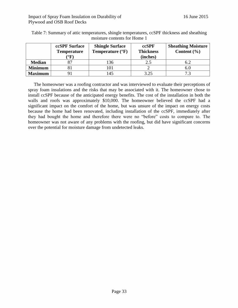
Impact of Spray Foam Insulation on Durability of
Plywood and OSB Roof Decks
16 June 2015
Page 33
Table 7: Summary of attic temperatures, shingle temperatures, ccSPF thickness and sheathing
moisture contents for Home 1
ccSPF Surface
Temperature
(°F)
Shingle Surface
Temperature (°F)
ccSPF
Thickness
(inches)
Sheathing Moisture
Content (%)
Median 87 136 2.5 6.2
Minimum 81 101 2 6.0
Maximum 91 145 3.25 7.3
The homeowner was a roofing contractor and was interviewed to evaluate their perceptions of
spray foam insulations and the risks that may be associated with it. The homeowner chose to
install ccSPF because of the anticipated energy benefits. The cost of the installation in both the
walls and roofs was approximately $10,000. The homeowner believed the ccSPF had a
significant impact on the comfort of the home, but was unsure of the impact on energy costs
because the home had been renovated, including installation of the ccSPF, immediately after
they had bought the home and therefore there were no “before” costs to compare to. The
homeowner was not aware of any problems with the roofing, but did have significant concerns
over the potential for moisture damage from undetected leaks.
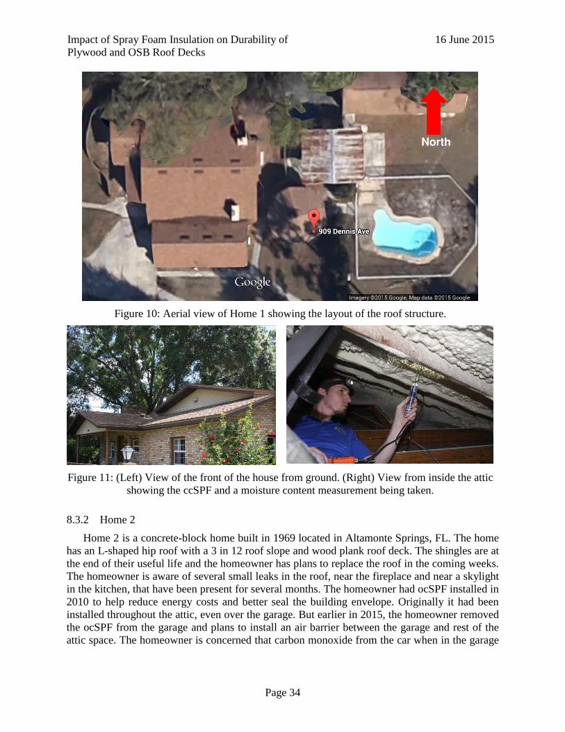
Impact of Spray Foam Insulation on Durability of
Plywood and OSB Roof Decks
16 June 2015
Page 34
Figure 10: Aerial view of Home 1 showing the layout of the roof structure.
Figure 11: (Left) View of the front of the house from ground. (Right) View from inside the attic
showing the ccSPF and a moisture content measurement being taken.
8.3.2 Home 2
Home 2 is a concrete-block home built in 1969 located in Altamonte Springs, FL. The home
has an L-shaped hip roof with a 3 in 12 roof slope and wood plank roof deck. The shingles are at
the end of their useful life and the homeowner has plans to replace the roof in the coming weeks.
The homeowner is aware of several small leaks in the roof, near the fireplace and near a skylight
in the kitchen, that have been present for several months. The homeowner had ocSPF installed in
2010 to help reduce energy costs and better seal the building envelope. Originally it had been
installed throughout the attic, even over the garage. But earlier in 2015, the homeowner removed
the ocSPF from the garage and plans to install an air barrier between the garage and rest of the
attic space. The homeowner is concerned that carbon monoxide from the car when in the garage

Impact of Spray Foam Insulation on Durability of
Plywood and OSB Roof Decks
16 June 2015
Page 35
will become trapped in the attic space and become dangerous for the occupants. The HVAC
system is located outside the home.
Figure 12: (Left) Aerial view of Home 2. The red dot indicates the approximate location of the
photo to the right. (Right) ocSPF installed in the attic space. The truss shown is directly over the
garage wall. SPF to the right of the truss, over the garage, has been removed by the homeowner.
Moisture contents, ocSPF surface temperatures and ocSPF thickness were measured at
multiple locations in the attic. The data is summarized in Table 8. The full data is available in
Appendix A. Shingle surface temperatures were not taken because it was 6:30 PM when the
home was inspected and the sun was already obscured by neighboring trees. No evidence of
elevated moisture contents were observed in the wood decking, but we were unable to access the
areas with known leaks due to their locations near the eave of the attic. When the homeowner
replaces the roof in a few weeks however, it would be beneficial to observe the moisture contents
and condition of the roof deck when the shingles are removed.
Table 8: Summary of ocSPF surface temperatures, thickness and roof deck moisture contents
in Home 2
ocSPF Surface
Temperature
(°F)
Shingle Surface
Temperature (°F)
ocSPF
Thickness
(inches)
Sheathing
Moisture Content
(%)
Median 94
No Data
5.4 6.0
Minimum 93 3.5 6.0
Maximum 95 7.5 6.1
The homeowner installed the ocSPF in January 2010 after many hours of personal research
into the benefits and potential problems. The cost of the installation was $4,500. The homeowner
perceives some benefit to it, noticing that the AC runs less throughout the day. This has resulted
in slightly lower energy costs. But the homeowner is unsure of whether he wants to keep the
foam or not, and is considering taking it out before replacing the roof. The homeowner is
somewhat concerned about moisture problems with the foam, but is mostly concerned about air
quality. An air test was performed several years installation of the ocSPF and the results
indicated elevated levels of CO2 in comparison to typical levels in homes. The homeowner is
concerned that the installation of the ocSPF without consideration of the entire building envelope
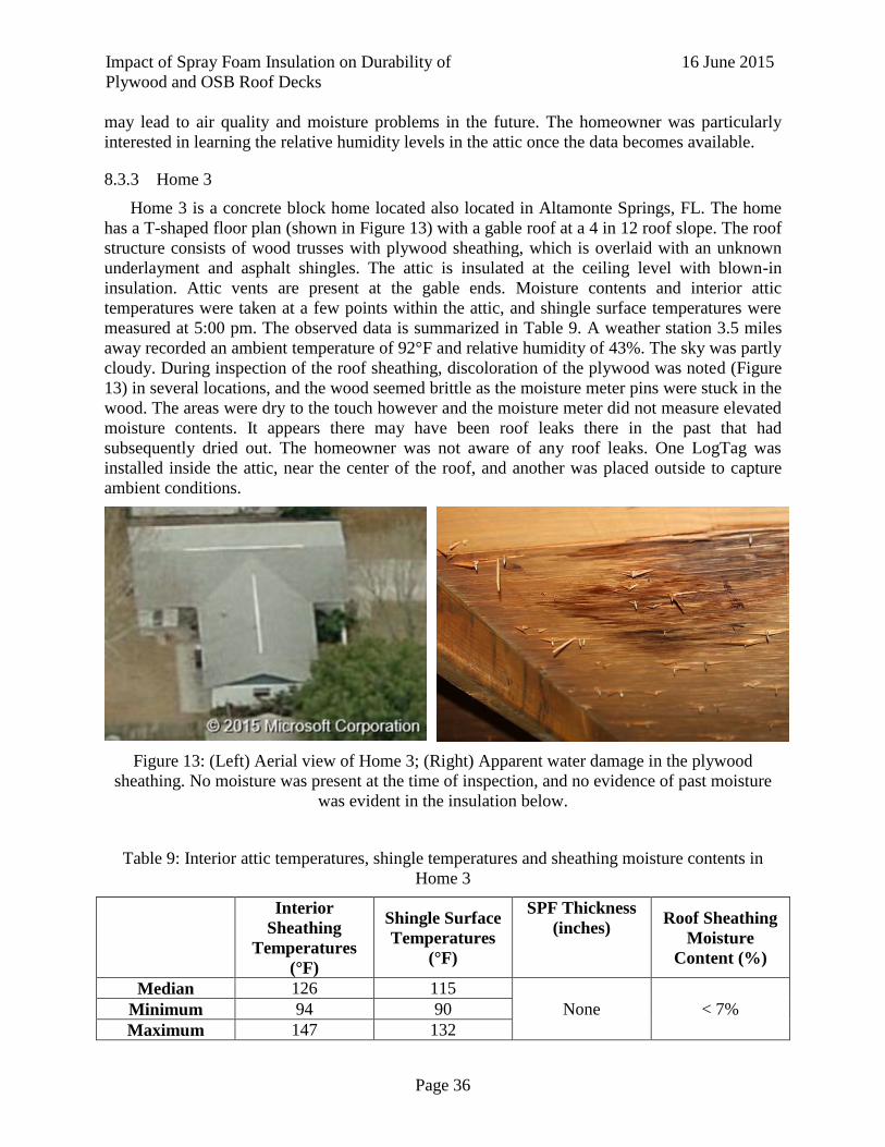
Impact of Spray Foam Insulation on Durability of
Plywood and OSB Roof Decks
16 June 2015
Page 36
may lead to air quality and moisture problems in the future. The homeowner was particularly
interested in learning the relative humidity levels in the attic once the data becomes available.
8.3.3 Home 3
Home 3 is a concrete block home located also located in Altamonte Springs, FL. The home
has a T-shaped floor plan (shown in Figure 13) with a gable roof at a 4 in 12 roof slope. The roof
structure consists of wood trusses with plywood sheathing, which is overlaid with an unknown
underlayment and asphalt shingles. The attic is insulated at the ceiling level with blown-in
insulation. Attic vents are present at the gable ends. Moisture contents and interior attic
temperatures were taken at a few points within the attic, and shingle surface temperatures were
measured at 5:00 pm. The observed data is summarized in Table 9. A weather station 3.5 miles
away recorded an ambient temperature of 92°F and relative humidity of 43%. The sky was partly
cloudy. During inspection of the roof sheathing, discoloration of the plywood was noted (Figure
13) in several locations, and the wood seemed brittle as the moisture meter pins were stuck in the
wood. The areas were dry to the touch however and the moisture meter did not measure elevated
moisture contents. It appears there may have been roof leaks there in the past that had
subsequently dried out. The homeowner was not aware of any roof leaks. One LogTag was
installed inside the attic, near the center of the roof, and another was placed outside to capture
ambient conditions.
Figure 13: (Left) Aerial view of Home 3; (Right) Apparent water damage in the plywood
sheathing. No moisture was present at the time of inspection, and no evidence of past moisture
was evident in the insulation below.
Table 9: Interior attic temperatures, shingle temperatures and sheathing moisture contents in
Home 3
Interior
Sheathing
Temperatures
(°F)
Shingle Surface
Temperatures
(°F)
SPF Thickness
(inches) Roof Sheathing
Moisture
Content (%)
Median 126 115
None < 7% Minimum 94 90
Maximum 147 132

Impact of Spray Foam Insulation on Durability of
Plywood and OSB Roof Decks
16 June 2015
Page 37
8.3.4 Summary of Field Investigations
Three homes were inspected to evaluate the effects of SPF insulation on wood sheathing.
Two of the homes had SPF insulation installed – one with ccSPF and the other with ocSPF – and
the third house did not have SPF insulation and served as a control. In all three homes, no
evidence of elevated moisture contents were observed, with moisture contents at every location
measured being less than 8%. Home 2 did have a couple of known leaks in the roof, but the areas
with the leaks were inaccessible from the attic. The homeowner is planning to replace the roof
shingles in the coming weeks and it would be beneficial to observe the condition of the roof
decking when it is replaced. Interior attic temperatures were lowest in the ccSPF roof (Home 1)
despite the inspection being performed in the house near the hottest time of the day.
Temperatures in the ocSPF roof (Home 2) were 4°F higher on average, despite being measured
near the end of the day. Temperatures in the vented attic (Home 3) were the highest of all with
median temperatures nearly 40°F higher than those in the unvented attics. Median shingle
surface temperatures were 21°F higher in the unvented attic than in the vented attic for
approximately equal ambient temperatures. The temperatures of the shingles above the vented
attic were taken later in the day (5:00 PM versus 2:30 PM), which may have contributed to the
differences.
Table 10: Summary of Field Observations for ERP 2
Inspection
Time
Roof Deck
Insulation Type
Interior
Temperature (°F)
Shingle Surface
Temperature (°F)
Moisture
Content (%)
Home 1 2:37 PM ccSPF/3 in. 87 136 6.2
Home 2 6:30 PM ocSPF/5 in. 94 Not Measured 6.0
Home 3 5:00 PM None 126 115 < 7.0

Impact of Spray Foam Insulation on Durability of
Plywood and OSB Roof Decks
16 June 2015
Page 38
9 Experimental Research Plan 3A: Comparative Tests: Drying Rates of Insulated Uniformly Wetted Wood Roof Decks
9.1 Objective
The objective of this study is to evaluate the relative drying rates of wood roof deck
configurations with various foam insulation characteristics. The approach is to simulate a 1D
moisture movement out of a wood roof deck saturated at the start and subjected to a differential
temperature (exterior –interior) conditions.
9.2 Motivation
Small-scale proof of concept experiment is needed to confirm an approach for monitoring
roof deck drying rates. Experiment will be used as precursor to more elaborate testing, if this is
justified by results.
9.3 Approach
Fabricate 36, 12” x 12”, flat roof specimens and measure the 1-D comparative drying rates
through wood roof cross-sections having a) traditional (no insulation), b) open-cell and c) closed-
cell spray foam insulation. Measure interior and exterior climate for 1 month. Interior conditions
will be representative of a conditioned space. Exterior conditions will artificially simulate a
hot/humid climate via heat lamps and moisture released from samples. This will create a vapor
drive with hygrothermal properties typical of Climate zone 1. Roof sheathing will be water-
soaked at start of experiment up to a moisture content exceeding threshold for decay of 30%.
Moisture content will be monitored via gravimetric weighing per ASTM D4442 of removable
roof specimens. Relative humidity and temperature of interior and exterior space monitored with
Log Tag sensors.
Figure 14: Isometric view of Insulated Thermal Chamber

Impact of Spray Foam Insulation on Durability of
Plywood and OSB Roof Decks
16 June 2015
Page 39
9.3.1 Insulated Chamber
The Insulated Thermal Chamber is 11 ft by 5 ft by 6.5 ft tall (interior dimensions) (Figure
15). The insulation consists of R19 Batten Insulation and 2 in. thick Perma “R” polystyrene rigid
insulation board. The chamber consists of a thermally controlled portion housed above the roof
specimens and an ambient condition of the lab below subjected the specimens to an approximate
70F thermal variance (Figure 16). Thermal control is provided by two Radiant Electric Heat
1445CL surface mounted heaters that produce 5150 BTU of energy each. Each heater measures
46 in. by 15 in. by 1-1/8 in. and it is centered on the 1/3 points on the roof deck. The roof deck
temperature is thermostat controlled by two Johnson Control A419 thermostats to a set
temperature of 150F. Log Tag data loggers have been placed in 4 locations inside the “Top” of
the thermal chamber and 1 in the bottom ambient condition to capture the relative humidity and
temperature at various points in the structure. The roof deck supports the 36 specimens that are
approximately 22 in. below the heaters (Figure 16). The interior condition below the roof deck is
open to the laboratory – a semi-controlled space with average temperature 65.7 oF and relative
humidity of 48%.
Figure 15: Insulated Thermal Chamber
Figure 16: Thermally controlled top portion (Left) lower interior chamber open to ambient
Temperature (Right).
9.3.2 Specimen Fabrication
The roof specimens are 12 in. by 12 in. cross-sections of a typical roof system. Each
specimen (Plywood or OSB) has asphalt shingles and roofing underlayment (30# or Ice & Water

Impact of Spray Foam Insulation on Durability of
Plywood and OSB Roof Decks
16 June 2015
Page 40
Shield) installed (Figure 19). Table 11 provides the system matrix of the number of samples with
or without spray foam insulation (closed cell (ccSPF) or open cell (ocSPF)). Wood roof
sheathing was purchased from traditional hardware stores. Sheathing acclimated in the lab for
approximately 14 days. Moisture content was measured using a handheld DelmHorst Instrument
point moisture meter – Model BD-2100. Average moisture values for the sheathing were 7.24%
and 6.94% for plywood and OSB sheathing, respectively. All of the roof specimen constructed
can be seen in Table 11.
Figure 17: Chamber Test Deck
Table 11: System Matrix for Comparative Drying Rates
1-layer 30# Building
paper (1P)
2-layer 30# Building
paper (2P) Ice & Water Shield (SA)
Control
(no foam)
Open cell
foam
Closed
cell foam
Control
(no foam)
Open cell
foam
Closed
cell foam
Control
(no foam)
Open cell
foam
Closed
cell foam
Plywood X X X X X X X X X X X X X X X X X X
OSB X X X X X X X X X X X X X X X X X X
Spray foam insulation was installed by Gale Insulation in Alachua, FL on 03/27/15 beginning
at 8:30am. A grid system pre-fastened to the sheathing provided a 12 in. x 12 in x 3 in. opening
for insulation. A single-pass foam was used for the open cell spray foam application (ocSPF)
(Figure 2), and two passes used for the closed cell spray foam (ccSPF) application. For the
ocSPF the foam expansion was quite large, exceeding the depth of the samples. These samples
will maintain the “as sprayed” surface and form a “skin” which is representative of spray foam
insulation in practice.

Impact of Spray Foam Insulation on Durability of
Plywood and OSB Roof Decks
16 June 2015
Page 41
Figure 18: Installation of open-celled SPF insulation
Samples were allowed to cure for 48 hours before the samples were separated from the wood
framing. The edges of the wood sheathing and spray foam insulation were coated with two
waterproofing coats using Gaco Roof to minimize chance of lateral moisture transfer and ensure
1 dimensional drying. Each sample was weighed using an Ohaus Ranger 7000 digital scale and
placed in a plastic covered bin.
Figure 19: Cross Section of Roof Specimen
9.3.3 Wetting procedure
The initial moisture content of the wood sheathing for each sample was determined using a
Delmhorst BD-2100 hand-held moisture meter. The sample was then weighed in order to
determine the amount of water absorption necessary to reach the equilibrium wood saturation of
30% as seen in the calculation below.
Sample calculation:
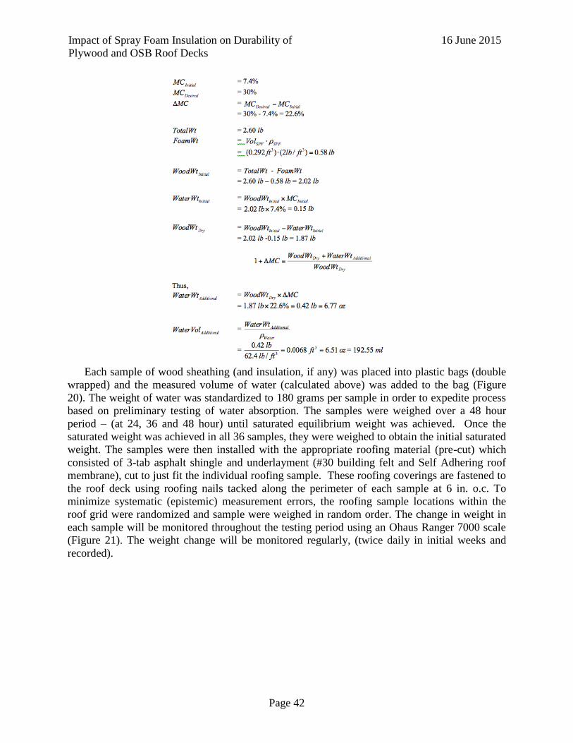
Impact of Spray Foam Insulation on Durability of
Plywood and OSB Roof Decks
16 June 2015
Page 42
Each sample of wood sheathing (and insulation, if any) was placed into plastic bags (double
wrapped) and the measured volume of water (calculated above) was added to the bag (Figure
20). The weight of water was standardized to 180 grams per sample in order to expedite process
based on preliminary testing of water absorption. The samples were weighed over a 48 hour
period – (at 24, 36 and 48 hour) until saturated equilibrium weight was achieved. Once the
saturated weight was achieved in all 36 samples, they were weighed to obtain the initial saturated
weight. The samples were then installed with the appropriate roofing material (pre-cut) which
consisted of 3-tab asphalt shingle and underlayment (#30 building felt and Self Adhering roof
membrane), cut to just fit the individual roofing sample. These roofing coverings are fastened to
the roof deck using roofing nails tacked along the perimeter of each sample at 6 in. o.c. To
minimize systematic (epistemic) measurement errors, the roofing sample locations within the
roof grid were randomized and sample were weighed in random order. The change in weight in
each sample will be monitored throughout the testing period using an Ohaus Ranger 7000 scale
(Figure 21). The weight change will be monitored regularly, (twice daily in initial weeks and
recorded).

Impact of Spray Foam Insulation on Durability of
Plywood and OSB Roof Decks
16 June 2015
Page 43
Figure 20: Wrapped sample being saturated
Figure 21: Weighing procedure for installed roof deck samples
9.3.4 Temperature and RH control
The temperature and relative humidity within the "attic" area below the samples are
maintained at climate conditions of the laboratory. The 18-ton HVAC system in this 7,000 sf
high-bay laboratory space can maintain a nominally constant temperature and remove moisture
to maintain relatively low relative humidity conditions. While moisture gain to the top side may
occur we are not planning to control for this moisture buildup, as the hot side of the chamber
represents “outside” conditions. Average relative humidity in Florida is generally high – i.e. 77%
yearly average for Gainesville, FL. The roof deck temperature is controlled by two Johnson
Control A419 thermostats to a set temperature of 150F. The thermostat will be placed at the roof
deck level, and connected to an on/off switch in series with ceramic heater circuit. The Advisory
Panel advised at the 21/22 January 2015 meeting to limit the thermal loading to constant
temperature difference and to evaluate moisture movement in a horizontal roof deck. This test
setup is not intended to simulate IR heat thermal load or actual moisture flow in sloped real roof
assemblies subjected to daily temperature fluctuations. Temperature and RH conditions were
monitored above and below the samples using LogTag data loggers at the four corners of the
structure, and the changes in moisture (i.e. sample weight) monitored over the test period.
Results from this experiment plan to be justified using a WUFI 1-D numerical simulation in the

Impact of Spray Foam Insulation on Durability of
Plywood and OSB Roof Decks
16 June 2015
Page 44
future to be used for comparison to the experimental moisture changes. Figure 22 and Figure 23
show temperatures and relative humidity for three locations within the “attic” area and one
location in the conditioned space at the entrance to the thermal chamber.
Figure 22: Log Tag Temperature Data
Figure 23: Log Tag Humidity Data
05/06 05/11 05/16 05/21 05/26 05/3120
30
40
50
60
70
80
Date (mm/dd)
Tem
per
atu
re
(C
)
Temperature
Location 1
Location 2
Location 3
Location 5
05/06 05/11 05/16 05/21 05/26 05/31
0
10
20
30
40
50
60
Date (mm/dd)
Rel
ativ
e H
um
idit
y (
RH
)
Humidity
Location 1
Location 2
Location 3
Location 5

Impact of Spray Foam Insulation on Durability of
Plywood and OSB Roof Decks
16 June 2015
Page 45
Figure 24: Map Location of Log Tag Placement (Note: Log Tag 1 is in lower level and 2-5 are
in the temperature controlled attic space.)
9.4 Results
The weights of the specimen were recorded daily. The time elapsed between each weighing
was taken by subtracting the date and time the sample was put in the thermal chamber from the
time it was weighed. The weight of each specimen against the time lapsed in hours was plotted.
This provides a general curve of the amount of water lost by the sample over time. Because each
sample had a different starting weight a normalized plot was made for each sheathing and
insulation type. The normalized results were obtained by taking the all the sample weights and
dividing them by the initial weight. These graphs show the deviation of the drying rate trends of
each sample.
0 100 200 300 400 500 600
0
0.2
0.4
0.6
0.8
1
Time Lapsed (Hours)
No
rmal
ized
Wei
gh
t o
f S
pec
imen
OSB Control(No Foam)
O1(1P)
O2(SA)
O3(SA)
O4(2P)
O5(1P)
O6(2P)
0 100 200 300 400 500 6000
0.2
0.4
0.6
0.8
1
Time Lapsed (Hours)
No
rmal
ized
Wei
gh
t o
f S
pec
imen
Plywood Control (No Foam)
P1(2P)
P2(SA)
P3(SA)
P4(2P)
P5(1P)
P6(1P)

Impact of Spray Foam Insulation on Durability of
Plywood and OSB Roof Decks
16 June 2015
Page 46
Figure 25: Normalized Drying Rate Data
0 100 200 300 400 500 6000
0.2
0.4
0.6
0.8
1
Time Lapsed (Hours)
No
rmal
ized
Wei
gh
t o
f S
pec
imen
OSB Closed Cell Foam
OC1(SA)
OC2(SA)
OC3(1P)
OC4(2P)
OC5(2P)
OC6(1P)
0 100 200 300 400 500 6000
0.2
0.4
0.6
0.8
1
Time Lapsed (Hours)
No
rmal
ized
Wei
gh
t o
f S
pec
imen
Plywood Closed Cell Foam
PC1(SA)
PC2(2P)
PC3(SA)
PC4(1P)
PC5(2P)
PC6(1P)
0 100 200 300 400 500 6000
0.2
0.4
0.6
0.8
1
Time Lapsed (Hours)
No
rmal
ized
Wei
gh
t o
f S
pec
imen
OSB Open Cell Foam
OO1(2P)
OO2(SA)
OO3(1P)
OO4(2P)
OO5(SA)
OO6(1P)
0 100 200 300 400 500 6000
0.2
0.4
0.6
0.8
1
Time Lapsed (Hours)
No
rmal
ized
Wei
gh
t o
f S
pec
imen
Plywood Open Cell Foam
PO1(SA)
PO2(1P)
PO3(2P)
PO4(1P)
PO5(SA)
PO6(2P)
0 100 200 300 400 500 600 7000
0.2
0.4
0.6
0.8
1
Time Lapsed (Hours)
No
rmal
ized
Wei
gh
t o
f S
pec
imen
(g
/g)
1P
OSB Control
OSB Closed
OSB Open)
Plywood Control
Plywood Closed
Plywood Open
0 100 200 300 400 500 600 700 8000
0.2
0.4
0.6
0.8
1
Time Lapsed (Hours)
No
rmal
ized
Wei
gh
t o
f S
pec
imen
(g
/g)
SA
OSB Control
OSB Closed
OSB Open)
Plywood Control
Plywood Closed
Plywood Open

Impact of Spray Foam Insulation on Durability of
Plywood and OSB Roof Decks
16 June 2015
Page 47
Figure 26: Normalized Data
In this study, half-life was used to evaluate the drying rates of all the specimen from the
thermal chamber testing. It is representative of the amount of time required for the amount of
water weight to fall to half its initial value. The term is used more generally for discussing any
type of exponential decay. It has been well established that the exponential decay function is
adequate to fit the curves of the weight change of all this specimen from this study, as illustrated
in Figure 25 and Figure 26. We obtained the half-life of 36 samples by interpolating their
individual weight variation curves. Figure 27 presents the 36 half-life times, along with the mean
and standard deviation of each group of data. Results showed that the mean of the half-life for
the plywood specimen with ccSPF installed is the highest among six groups. As compared with
the plywood specimen with ccSPF, the ccSPF OSB roof panels have a shorter half-life time, but
still superior to others. As a whole, the installation of ccSPF slows down the drying process of
roof panels, regardless of the types of underlayment and roof panel materials.
Figure 27: Half-life for all specimen
0 100 200 300 400 500 600 7000
0.2
0.4
0.6
0.8
1
Time Lapsed (Hours)
No
rmal
ized
Wei
gh
t o
f S
pec
imen
(g
/g)
2P
OSB Control
OSB Closed
OSB Open)
Plywood Control
Plywood Closed
Plywood Open
No Foam ocSPF ccSPF0
10
20
30
40
50
60
70
80
Hal
f L
ife
(in
Ho
urs
)
OSB Specimen
Plywood Specimen
1 Ply 30# felt
2 Ply 30# felt
Self Adhering membrane

Impact of Spray Foam Insulation on Durability of
Plywood and OSB Roof Decks
16 June 2015
Page 48
Figure 28: Interaction plot for different roof panel materials
As mentioned earlier, two random samples were measured in this study for each roof panel
material, each type of underlayment and each foam installation. We took the average of the two
repetitions and plotted them in Figure 28. It was observed that OSB samples have a larger half
time than plywood samples, except in the case of specimen with ccSPF installed. It indicates that
there is an interaction between the foam installation and roof panel materials.
OSB Plywood0
10
20
30
40
50
60
70
Roof Panel Material
Hal
f L
ife
(in
Ho
urs
)
No Foam (1P)
ccSPF (1P)
ocSPF (1P)
No Foam (2P)
ccSPF (2P)
ocSPF (2P)
No Foam (SA)
ccSPF (SA)
ocSPF (SA)

Impact of Spray Foam Insulation on Durability of
Plywood and OSB Roof Decks
16 June 2015
Page 49
Figure 29: Interaction plot for different foam installations
Figure 29 presents the interaction plot of the samples with various foam installations. The
half-life of ccSPF samples is the highest, whereas ocSPF samples have the lowest half-life,
except for plywood sample with self-adhering underlayment.
Figure 30: Interaction plot for different types of underlayment
Figure 30 presents the interaction plot of samples with different types of underlayment.
Generally, the samples with self-adhering underlayment have a higher half-life than the other
No Foam ccSPF ocSPF0
10
20
30
40
50
60
70
Foam Installation
Hal
f L
ife
(in
Ho
urs
)
OSB (1P)
Plywood (1P)
OSB (2P)
Plywood (2P)
OSB (SA)
Plywood (SA)
1P 2P SA0
10
20
30
40
50
60
70
Underlayment
Hal
f L
ife
(in
Ho
urs
)
OSB, No Foam
OSB, ccSPF
OSB, ocSPF
Plywood, No Foam
Plywood, ccSPF
Plywood, ocSPF

Impact of Spray Foam Insulation on Durability of
Plywood and OSB Roof Decks
16 June 2015
Page 50
two types of underlayment. It means that the installation of self-adhering underlayment slows
drying process of wood member.
9.5 Conclusions
Findings from ERP 3a are summarized below.
The average drying rates for all underlayment types, from fastest to slowest are ranked as
follows:
1) Plywood ocSPF
2) Plywood Control
3) OSB ocSPF
4) OSB Control
5) OSB ccSPF
6) Plywood ccSPF
Multiple underlayment plys did not affect drying rates.
Self-adhered membrane slowed the drying rate compared to 30# felt underlayments in
five of the six specimens.

Impact of Spray Foam Insulation on Durability of
Plywood and OSB Roof Decks
16 June 2015
Page 51
10 Experimental Research Plan 3B: Point Source Water Leakage
10.1 Objective
The objectives of this research are to determine: (i) the rate of moisture spread in plywood
and OSB roof decking from a point leak source; (ii) if a non-destructive method of detecting
moisture due to a roof leak is feasible (using Infra-red photography). The study will advance our
understanding of the moisture movement along and within a wood roof deck having a moisture
impermeable layer applied to its underside.
10.2 Motivation
To determine the moisture spreading effect over time that spray foam and roof sheathing
have when subjected to a typical roof failure and leakage scenario. The purpose is to perform
comparative testing to existing homes with roof damage and spray foam.
10.3 Approach
Fabricate 64, 2’x4’, test samples with 2 in 12 mono-sloped south-facing roof pitch installed
with spray foam insulation to determine the spread of moisture from a point source leak. The
south orientation yields the highest moisture contents (Prevatt et al. 2014) and the constant roof
slope is typical of one side of a roof assembly. Specimens were exposed to a continuous drip of
water between 1-3 mL/min for up to 8 weeks. The methodology for the point source leakage is
from (Prevatt et al. 2014) in which a series of drip emitters will provide continuous wetting. The
moisture accumulation over time will be monitored via gravimetric sampling of 4” x 4” roof
samples per ASTM D4442. These moisture contents will be plotted versus time to develop
contour plots to show the spread of moisture throughout sheathing. This will answer: (A) Does
Peel and Stick limit absorption of moisture into wood? and (B) Does having 2 vapor retarders
(top-underlayment, bottom- SPF) limit drying of moisture? The full test matrix is provided in
Table 12.
Table 12: Test Matrix for ERP 3b
Exposure Period
OSB Plywood
#30 Felt - 1 layer Peel and Stick #30 Felt - 1 layer Peel and Stick
No Foam ccSPF No Foam ccSPF No Foam ccSPF No Foam ccSPF
Start X X X X X X X X
1 week X X X X X X X X
2 week X X X X X X X X
2 week - No Leak X X X X X X X X
4 week X X X X X X X X
6 week X X X X X X X X
8 week X X X X X X X X
8 week - No Leak X X X X X X X X
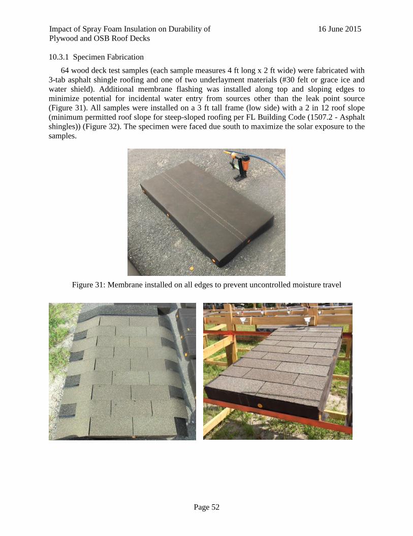
Impact of Spray Foam Insulation on Durability of
Plywood and OSB Roof Decks
16 June 2015
Page 52
10.3.1 Specimen Fabrication
64 wood deck test samples (each sample measures 4 ft long x 2 ft wide) were fabricated with
3-tab asphalt shingle roofing and one of two underlayment materials (#30 felt or grace ice and
water shield). Additional membrane flashing was installed along top and sloping edges to
minimize potential for incidental water entry from sources other than the leak point source
(Figure 31). All samples were installed on a 3 ft tall frame (low side) with a 2 in 12 roof slope
(minimum permitted roof slope for steep-sloped roofing per FL Building Code (1507.2 - Asphalt
shingles)) (Figure 32). The specimen were faced due south to maximize the solar exposure to the
samples.
Figure 31: Membrane installed on all edges to prevent uncontrolled moisture travel

Impact of Spray Foam Insulation on Durability of
Plywood and OSB Roof Decks
16 June 2015
Page 53
Figure 32: Asphalt Shingle Installation (Left) and Sample Placement (Right)
10.3.2 Wetting Procedure
An in-line non pressure actuating drip emitters attached to ¼ inch tubing at a slope of ¼ inch
per foot point was installed at the center of each sample 4 inches from the high side (Figure 33).
A calibrated, consistent rate of water of 1-3 mL/min will pass directly to the roof deck through a
5/8” diameter hole in the roofing and underlayment. A 4 inch pressure head is maintained by
supply reservoirs which have intake and outflow valves to keep the pressure head constant
(Figure 34). The experiment was constructed outside of the Powell Lab and exposed to existing
Gainesville weather, including natural thermal cycling, in addition to the point-source water leak
during the 8-week exposure period. Temperature and relative humidity readings will be recorded
from the local airport weather station that is 1.65 miles from the test site.
Figure 33: Drip Emitter Diagram (Left) Drip Emitter Test Setup (Right)
Figure 34: Complete Test Configuration
10.3.3 Data Acquisition
At the end of Weeks 1, 2, 3, 4, 6 and 8, one set of samples was harvested. For each sample,
(25) 4 in. by 4 in. gravimetric specimens was extracted from a sample (Figure 36) and the spray
foam was carefully cut from the sheathing specimen without damaging the sheathing. The
samples are wrapped in cellophane to seal moisture before weighing within 24 hours with an
OHAUS Ranger 7000 scale. The moisture contents of each specimen were determined per
ASTM D 4442.

Impact of Spray Foam Insulation on Durability of
Plywood and OSB Roof Decks
16 June 2015
Page 54
It should be noted that, as can be seen in Figure 35, mineral deposits from the water formed
over time on the drippers and slowed the dripping rate below the desired 1-3 mL/min. This was
unexpected and the differences in drip rate were not obvious until week 6. All of the drippers
over the week 8 samples were replaced at week 6 and checked to ensure a consistent flow rate,
but it is probable that Week 6 samples, and possibly even some Week 4 samples, experienced
slower dripper flow rates than Week 1 and 2 samples.
Figure 35: Old dripper with mineral deposits indicated by white ellipse
Figure 36: Specimen numbering scheme
At the end of week 8, the spread of moisture in the samples will be quantified using an FLIR
Thermacam PM 695 infrared camera.
A B C D E
1
2
3
4
5

Impact of Spray Foam Insulation on Durability of
Plywood and OSB Roof Decks
16 June 2015
Page 55
10.4 Results
The weight of moisture in grams for each gravimetric sample was summed for each specimen
to obtain a total moisture weight. This provides a measure of the total moisture absorbed into the
specimen after the end of the exposure period, giving a quantitative comparison of the moisture
retention in the various specimens. Table 2 gives the preliminary moisture results for each
specimen.
Table 13: Total Moisture (g) in the 25 gravimetric samples for each specimen in the test matrix
OSB Plywood
#30 Felt - 1 layer Peel and Stick #30 Felt - 1 layer Peel and Stick
No
Foam
ccSPF No
Foam
ccSPF No
Foam
ccSPF No
Foam
ccSPF
Start 200.5 163.7 159.3 134.1 172.7 165.2 192.8 135.1
1 week 627.0 1692.2 838.9 882.1 937.9 316.3 164.4 174.4
2 week 843.1 2011.1 528.9 1748.0 985.2 1034.7 36.6 415.2
2 week – No
Drip
125.6 109.6 114.4 118.6 147.7 132.7 144.9 90.9
4 week 978.0 1788.9 602.7 1825.2 152.5 826.2 195.5 264.4
6 week1 143.2 1231.1 237.5 1060.1 362.8 632.6 130.9 204.0
8 week X X X X X X X X
8 week - No
Leak
X X X X X X X X
The spread of moisture within the samples over time is visualized using contour plots,
interpolating the moisture contents based on the moisture data from the 25 gravimetric samples
within each specimen. The contours are presented below by week, with labels at the top of each
plot identifying the specimen type. The plots are oriented such that the specimens sloped from
top to bottom. The location of the point leak source is identified by the red circle. Black
rectangles indicate the center point of the 4 inch by 4 inch gravimetric samples.
Week 0

Impact of Spray Foam Insulation on Durability of
Plywood and OSB Roof Decks
16 June 2015
Page 56
Week 1
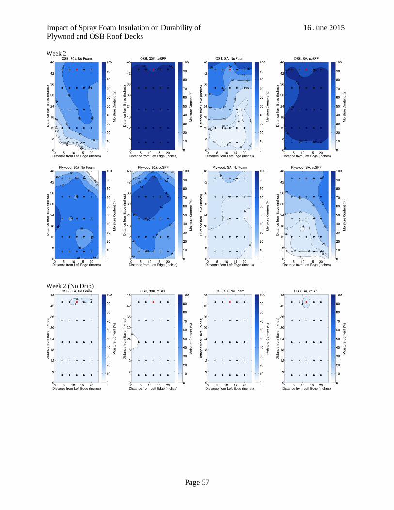
Impact of Spray Foam Insulation on Durability of
Plywood and OSB Roof Decks
16 June 2015
Page 57
Week 2
Week 2 (No Drip)
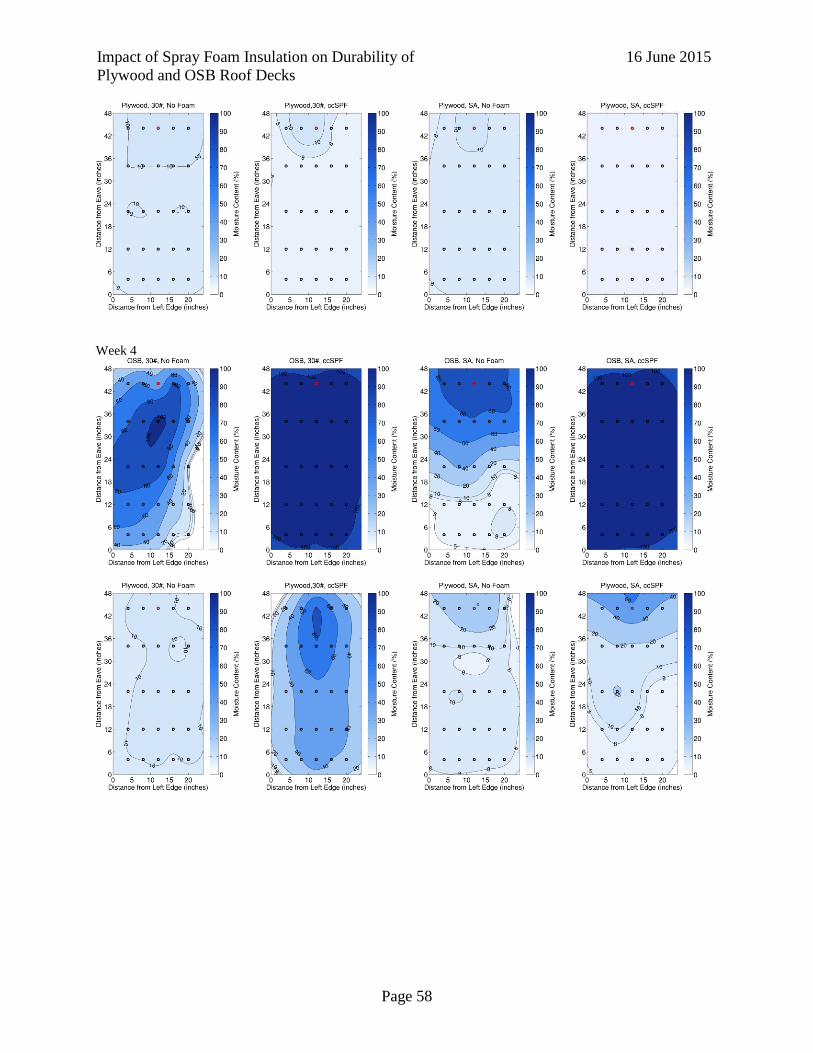
Impact of Spray Foam Insulation on Durability of
Plywood and OSB Roof Decks
16 June 2015
Page 58
Week 4

Impact of Spray Foam Insulation on Durability of
Plywood and OSB Roof Decks
16 June 2015
Page 59
Week 6
Week 8
[Data to be added]
Week 8 (No Drip)
[Data to be added]
10.5 Conclusions
The point leak source is clearly visible in many of the specimens through the high moisture
contents centered around the location of the leak source. The moisture tends to emanate away
from this point towards the sides and bottom of the specimen over time. The moisture travel
down the slope of the roof (from top to bottom) is evident by comparing Week 1 samples to the
ensuing weeks. By Week 2, the OSB samples with ccSPF are saturated (moisture contents near
100%), and this trend continues for most samples in Week 4. In Week 6, the effect of the slower
drip rates is obvious with the total moisture significantly less than in preceding weeks. Overall
the spread of moisture is relatively uniform, i.e., there are no significant irregularities or
discontinuities in the contours themselves, which could be an indication of poor quality data.

Impact of Spray Foam Insulation on Durability of
Plywood and OSB Roof Decks
16 June 2015
Page 60
Observations:
In samples with drip leaks, 15 of the 16 samples with ccSPF had higher total moisture
than the equivalent specimen without ccSPF.
In samples without leaks, total moisture remained low throughout, although plywood
specimens had more moisture than OSB specimens.
Peel and stick was more effective at limiting moisture accumulation in plywood
samples than in OSB samples.
The highest total moisture, 2011 grams, was observed in the OSB specimen with 30#
felt and ccSPF after two week exposure. The third and fifth highest moisture totals
were also observed in this specimen type, for one week and four week exposures.
In general for specimens with ccSPF, OSB specimens had higher moisture totals than
plywood specimens.

Impact of Spray Foam Insulation on Durability of
Plywood and OSB Roof Decks
16 June 2015
Page 61
11 Experimental Research Plan 4: Numerical hygrothermal model of wood roof deck samples with SPF insulation
11.1 Objective
Develop 1-D hygrothermal models of wood roof deck systems with installed spray foam
insulation. Originally, this ERP sought to develop a numerical model of moisture movement in
the roofs of the existing roofs in ERP 2 – Field Studies. However, during Advisory Panel
Meeting it was decided that given the number of unknown factors in the existing construction
this would not provide useful information, within timeframe of the project. As a result, the
Advisory panel suggested modifying ERP 4 to simulate replicating the moisture movement in
experimental samples conducted by the University of Florida research team, described in
Experimental Research Plan 3a (ERP 3a).
The motivation for this work is that the simulated hygrothermal movement is predicated
through numerical simulation is well established for one-directional moisture movement related
to temperature fluctuations. The experimental samples were kept within a limited temperature
range.
11.2 Test Set Up
Engineering Consultants Simpson Gumpertz & Heger Inc. (SGH) is performing
hygrothermal (combined heat + moisture migration) simulations of the various asphalt shingle
roof systems evaluated as part of this project. They are using the WUFI 5.3 computer program,
developed by the Fraunhofer Institute for Building Physics, to simulate drying rates for a variety
of insulated and uninsulated roof systems, in effect simulating the same
insulation/underlayment/roof sheathing configurations that were included in the physical test
samples of ERP 3a, described in Section 5, above. WUFI is a finite element simulator that
calculates heat and moisture flows based on defined material properties, surface transfer
coefficients, and time varying interior and exterior environmental conditions.
We re-created the laboratory tests using WUFI, matching the material geometries and initial
wetting of the sheathing per the laboratory procedures. We will compare the model results to
those obtained in the lab to better understand how closely the model represents the physical
phenomena related to drying in these roof assemblies. Once the correlation between the model
and the physical testing has been established, we will perform an additional series of analyses to
evaluate drying potential at different insulation thicknesses than those reviewed in the laboratory.
Our final analysis will include a comparison of our WUFI analysis with the laboratory
results, based on both relative drying rates and “half life” for the initial wetting as described in
the report.
This analysis is currently underway by SGH and their results will be presented during the
Roofing TAC meeting.
Impact of Spray Foam Insulation on Durability of
Plywood and OSB Roof Decks
16 June 2015
Page 62
12 References
Alturkistani, A., Fazio, P., Rao, J., and Mao, Q. (2008). "A new test method to determine the
relative drying capacity of building envelope panels of various configurations." Building
and Environment, 43(12), 2203-2215.
Carll, C., and Wiedenhoeft, A. C. (2009). "Moisture-related properties of wood and the effects of
moisture on wood and wood products." Moisture control in buildings: the key factor in
mold prevention, 2nd ed. West Conshohocken, PA: ASTM International, 54-79.
Derome, D., and Fazio, P. (2000). "Large-scale testing of two flat roof assemblies insulated with
cellulose." Journal of architectural engineering, 6(1), 12-23.
EPA (2012). "An Introduction to Indoor Air Quality: Volatile Organic Carbons (VOCs)."
<http://www.epa.gov/iaq/voc.html>.
EPA (2015). "Spray Polyurethane Foam (SPF) Home."
<http://www.epa.gov/oppt/spf/spray_polyurethane_foam.html>. (6/14, 2015).
Griffin, D. M. (1977). "Water potential and wood-decay fungi." Annual Review of
Phytopathology, 15(1), 319-329.
Grin, A., Smegal, J., and Lstiburek, J. (2013). "Application of Spray Foam Insulation Under
Plywood and OSB Roof Sheathing." Building America Report–1312.
Hendron, R., Anderson, R., Reeves, P., and Hancock, E. (2002). Thermal performance of
unvented attics in hot-dry climates, National Renewable Energy Laboratory.
Huang, Y.-C. T., and Tsuang, W. (2014). "Health effects associated with faulty application of
spray polyurethane foam in residential homes." Environmental Research, 134(0), 295-
300.
Lstiburek, J. (2002). "Moisture control for buildings." ASHRAE journal, 44(2), 36-41.
Nelson, P. E., and Der Ananian, J. S. (2009). "Compact asphalt shingle roof systems: Should
they be vented?" Journal of ASTM International, 6(4).
Nofal, M., and Kumaran, K. (2003). "Behavior of engineered wood materials under the effect of
wetting and drying cycles." Citeseer.
Ojanen, T., and Ahonen, J. (2005). "Moisture performance properties of exterior sheathing
products made of spruce plywood or OSB." VTT Working Papers 1459 7683
(http://www. vtt. fi/inf/pdf/) 2005.
Ojanen, T. T. (2001). "Thermal and Moisture Performance of a Sealed Cold-Roof System with a
Vapor-Permeable Underlay." Thermal Performance of the Exterior Envelopes of
Buildings VIII.
Pallin, S., Kehrer, M., and Miller, W. A. (2013). "A Hygrothermal Risk Analysis Applied to
Residential Unvented Attics." Oak Ridge National Laboratory (ORNL).
Prevatt, D., McBride, K., Roueche, D., and Masters, F. (2014). "Wind Uplift Capacity of Foam-
Retrofitted Roof Sheathing Panels Subjected to Rainwater Intrusion." Journal of
Architectural Engineering, B4014001.
Prevatt, D. O. (2010). "Field evaluation of thermal performance and energy efficiency of ccSPF
retrofitted vented residential attic." Rep. No. UF01-10, Univ. of Florida, Gainesville, FL.
Prevatt, D. O. (2013). "Spray-foam Retrofit of Wood Residential Roofs Interim Report."Sea
Grant.
Prevatt, D. O. "Wind Uplift Capacity of Foam Retrofitted Roof Sheathing Subjected to Water
Leaks." Proc., Residential Building Design Conference.

Impact of Spray Foam Insulation on Durability of
Plywood and OSB Roof Decks
16 June 2015
Page 63
Rose, J. D., and American Plywood, A. (1998). "Preliminary testing of wood structural panel
shear walls under cyclic (reversed) loading." American Plywood Association.
Rudd, A. (2005). "Field Performance of Unvented Cathedralized (UC) attics in the USA."
Journal of Building Physics, 29(2), 145-169.
Saber, H. H., Lacasse, M. A., Swinton, M. C., and Kumaran, M. K. (2010). "Benchmarking of
hygrothermal model against measurements of drying of full-scale wall assemblies."
Salonvaara, M., Karagiozis, A., and Desjarlais, A. "Moisture Performance of Sealed Attics in
Climate Zones 1 to 4." Proc., Thermal Performance of the Exterior Envelope of Whole
Buildings XII International Conference.
Schumaker, C. (2007). "BSD-149: Unvented Roof Assemblies for All Climates — Building
Science Information." Building Science Corporation.
Shreyans, S. (2011). "Thermal performance of foam retrofitted vented residential attic."
Straube, J., Smegal, J., and Smith, J. (2010). "Moisture-Safe Unvented Wood Roof Systems."
Buildingscience. com.
Timusk, P. C. (2008). An investigation of the moisture sorption and permeability properties of
mill-fabricated oriented strandboard.
Trechsel, H. R. (2001). Moisture Analysis and Condensation Control in Building Envelopes,
ASTM.
Tsuang, W., and Huang, Y.-C. T. (2012). "Asthma Induced by Exposure to Spray Polyurethane
Foam Insulation in a Residential Home." Journal of Occupational and Environmental
Medicine, 54(3).
Viitanen, H. A. (1997). "Modelling the time factor in the development of mould fungi-The effect
of critical humidity and temperature conditions on pine and spruce sapwood."
Holzforschung-International Journal of the Biology, Chemistry, Physics and Technology
of Wood, 51(1), 6-14.
Wu, Q., and Ren, Y. (2000). "Characterization of sorption behavior of oriented strandboard
under long-term cyclic humidity exposure condition." Wood and fiber science, 32(4),
404-418.
Wu, Y., Fazio, P., and Kumaran, M. (2008). "Moisture buffering capacities of five North
American building materials." Journal of Testing and Evaluation, 36(1), 489.

Impact of Spray Foam Insulation on Durability of
Plywood and OSB Roof Decks
16 June 2015
Page 64
13 Appendix
A. ERP 2 House Inspection Data
a. House 1
Attic
Location Temp (°C)
Thickness (in)
MC (%)
L1 27.2 3 7.3
L2 28 2 7/8 6.7
L3 28.4 3 6
L4 28.8 3 1/4 6.2
L5 28.6 2 3/8 6.3
L6 32.4 2 1/4 6.6
L7 31.6 2 1/2 7
L8 28.6 2 7/8 6
L9 30.6 2 1/2 6
L10 32.4 2 3/4 6.2
L11 31.4 2 1/4 6.3
L12 28.4 2 1/2 6
L13 33 2 6
L14 31 2 1/2 6
L15 31.8 2 5/8 6.5
L16 31.5 2 1/4 6
L17 30.2 2 1/4 6
L18 31.2 2 1/2 6.1

Impact of Spray Foam Insulation on Durability of
Plywood and OSB Roof Decks
16 June 2015
Page 65
Shingle Surface Temperature
Readings
Location Temp (°C)
T1 34.6
T2 34.2
T3 35.0
T4 47.4
T5 42.8
T6 38.2
T7 56.8
T8 56.6
T9 54.4
T10 54.2
T11 61.4
T12 61.6
T13 54.8
T14 60.4
T15 59.8
T16 58.6
T17 60.4
T18 63.8
T19 58.4
T20 38.8
T21 59.0
Logtags
Logtag Serial#
S1 1310012680
S2 1310012684
S3 1310012678
S4 1310012679
S5 1310012682

Impact of Spray Foam Insulation on Durability of
Plywood and OSB Roof Decks
16 June 2015
Page 66
b. House 1 Questionaire

Impact of Spray Foam Insulation on Durability of
Plywood and OSB Roof Decks
16 June 2015
Page 67

Impact of Spray Foam Insulation on Durability of
Plywood and OSB Roof Decks
16 June 2015
Page 68

Impact of Spray Foam Insulation on Durability of
Plywood and OSB Roof Decks
16 June 2015
Page 69
c. House 2
Moisture Content
Location MC %
M1 6.0
M2 6.1
M3 6.0
M4 6.0
M5 6.0
M6 6.0
M7 6.1
M8 6.0
M9 6.1
Attic Temperature Readings
Location Temp (°C)
T1 34.6
T2 33.8
T3 34.2
T4 34.8
T5 34.8
T6 34.8
T7 34.4
T8 34.6
T9 34.8
Logtags
Logtag Serial#
S1 1310012681
S2 1310012683
S3 1310012686

Impact of Spray Foam Insulation on Durability of
Plywood and OSB Roof Decks
16 June 2015
Page 70
d. House 3
Asphalt Shingles Temperature
Location Temp (°C) Location
Temp (°C)
T1 46.4 T21 48.2
T2 41.8 T22 36.2
T3 36.2 T23 35.6
T4 44.2 T24 55.4
T5 34 T25 54.2
T6 34 T26 55
T7 44 T27 54.6
T8 35.8 T28 55.8
T9 38 T29 55.6
T10 37.4 T30 55.6
T11 32.8 T31 53.8
T12 48.6 T32 55.8
T13 47.2 T33 54.8
T14 40.8 T34 54.2
T15 35.2 T35 54.2
T16 32.4 T36 52.8
T17 52.8 T37 54.4
T18 32.4 T38 54.4
T19 33.6 T39 54
T20 49 T40 53.6
Logtags
Logtag Serial#
S1 1310012677
S2 1310012676

Impact of Spray Foam Insulation on Durability of
Plywood and OSB Roof Decks
16 June 2015
Page 71
Moisture Content
Location MC %
M1 6.1
M2
< 7 .0
M3
M4
M5
M6
M7
Attic Temperature Readings
Location Temp (°C)
T1 34.6
T2 34.2
T3 35.0
T4 47.4
T5 42.8
T6 38.2
T7 56.8
T8 56.6
T9 54.4
T10 54.2
T11 61.4
T12 61.6
T13 54.8
T14 60.4
T15 59.8
T16 58.6
T17 60.4
T18 63.8
T19 58.4
T20 38.8
T21 59.0

Impact of Spray Foam Insulation on Durability of
Plywood and OSB Roof Decks
16 June 2015
Page 72
e. House 3 Questionaire

Impact of Spray Foam Insulation on Durability of
Plywood and OSB Roof Decks
16 June 2015
Page 73

Impact of Spray Foam Insulation on Durability of
Plywood and OSB Roof Decks
16 June 2015
Page 74

Impact of Spray Foam Insulation on Durability of
Plywood and OSB Roof Decks
16 June 2015
Page 75

Impact of Spray Foam Insulation on Durability of
Plywood and OSB Roof Decks
16 June 2015
Page 76
B. Advisory Panel Meeting Minutes
a. 1-30-15 Advisory Panel Meeting Minutes
Impact of spray foam on the durability of plywood and OSB wood roof decks
Prepared by:
David O Prevatt and Trent Vogelgesang
University of Florida, Gainesville, FL
30 January 2015
NOTES OF Advisory Panel Meeting
Held on 21-22 January 2015, Hyatt Regency - Orlando, FL International Airport
Attendees: Table 14: 1-30-15 Meeting Attendees
In Person Webinar
Scott Kriner day1/day 2 Jaime Gascon, day1/day 2
Jason Hoerter, day1/day 2 Rick Olson, day 1
Mark Zehnal, day1/day 2 by webinar Sean O’Brien, day 1
Todd Wishneski, day1/day 2 David Brandon, day 1
Mike Fischer, day1/day 2 Yuh Chin T. Huang, day1/day 2
Mike Ennis, day1/day 2 Bill Coulbourne, day 1
Marcin Pazera, day1/day 2 Arlene Stewart, day1/day 2
John Broniek, day1/day 2 Tim Reinhold, day1/day 2
David Roodvoets, day1/day 2 Mo Mandani, day1/day 2
Tim Smail, day1/day 2 Rick Duncan, day 2
Eric Vaughn, day1/day 2
David Prevatt, day1/day 2
Trent Vogelgesang, day1/day 2
Mark Lisek, day 2
1. Day 1 – Literature Review and Data Collection – Prevatt – University of Florida
- Literature review: Research team requested Advisory Panel to provide additional reports
and peer-reviewed papers to add to literature review. In particular only two examples of
roofing performance issues were found. Broniek stated SPFA estimates that nationwide,
there are around 100,000 installed wood deck spray foam roofs. Question outstanding is
how widespread are the issues of moisture build-up?
o ACTION ITEM: UF will develop literature and circulate to Advisory Panel for
review. DATE? Sections will include structural performance, hygrothermal
modeling, health-related issues, experimental tests, field performance of
wood/spray foam composite roof decks.

Impact of Spray Foam Insulation on Durability of
Plywood and OSB Roof Decks
16 June 2015
Page 77
o Include history of Florida Building Code changes referring to SPF on wood roof
decks. Mike Fischer provided a summary for UF to review.
- Data Collection:
o ACTION ITEM: Request from SPFA to provide updated figures on volume and
number of wood/spray foam roof decks installed in Florida
Identify new construction versus retrofit.
o UF seeking timeline of foam installs related to changes in building code
2. Use of Spray Foam in Roofing: Broniek – Icynene
- Importance of fire retardants not addressed in UF literature review. May need to be
considered in testing with spray foam and code provisions related to include as a
parameter in testing.
ACTION ITEM: UF to consider including fire-retardant treatment issues within literature
review.
3. Field observations of damaged foam insulated roofs: Zehnal – FRSA
- Presented two homes that suffered problems – a) water related (via roof leaks) and b) due
to health-related issues of occupants. More quantifiable, fact-based information is needed
to justify the seriousness or extent of the problems.
o ACTION ITEM: Zehnal will request of FRSA members for additional
documentation on cases of problems related to wood/spray roof decks.
4. Contemporary Attic Construction in Residences: Brandon –Brandon Construction Company
- Brandon Construction Company is a GC company and they have used open cell spray
foam in roof deck construction for the past eight years with no issues. Their market is in
high-end custom homes. Brandon takes precaution such as evacuating the home for 48
hours and venting the home, providing supply and return ducts in the attic and avoiding
cold spots. Brandon uses mechanical engineers to size the ventilation system
- Recommendations:
o Evacuate building for 2 days after install – leave home open to vent.
o Condition all attics with supply and return ducts to cycle air.
o Ensure no “cold spots” by providing ventilation to all spaces of attic.
- ACTION ITEM: UF to include documentation for procedure and training needs to be
developed & followed for inspectors to ensure quality and safe installation. Should
installers be certified?
5. Health Related Issues to Spray foam insulation – Huang – Duke University
- Dr. Huang presented environmental medicine research related to health related issues to
inhabitants exposed to air contaminates suspected to be from spray foam insulation. His
research showed evidence that occupants developed asthma after installation of spray
foam. Several issues addressed in his presentation will be included in the literature
review.
6. ccSPF, Water and Wind resistance of roofs – Prevatt – University of Florida

Impact of Spray Foam Insulation on Durability of
Plywood and OSB Roof Decks
16 June 2015
Page 78
- Prevatt presented a summary of UF research on use of spray foam as a structural retrofit.
An approach using a below deck roof vent was found to reduce moisture content of wood
deck. The width of the vent was smaller than span of the roof trusses – which could
hamper drying potential at those (along-top chord) locations.
- Prevatt showed counter-intuitive photographs of higher moisture content in south-facing
roofs versus north-facing ones from UF previous testing – no consensus on reason.
7. Open Discussion
- Jason Hoerter (NCFI), closed cell is interchangeable with open cell foam if used
according to the manufacturer’s specifications. IMPORTANT to note this requirement.
- Open-celled foam has two opinions in Florida. Despite its high vapor permeance rating,
Zehnal stated that open-cell foam may form a water impermeable barrier under certain
conditions (shown via a small sample test).
- There was some discussion on terminology: Sealed, unsealed, conditioned, unconditioned
attics and spaces. ACTION ITEM: UF will include a definition of these spaces.
ADVISORY PANEL: Is there an industry-accepted interpretation?
o Sealed, “Unvented” – No ventilation to exterior exists.
o Unsealed, “Vented” – Ventilation to exterior exists.
o Conditioned – Supply and return duct in attic, also sealed to the exterior.
o Unconditioned- No supply and return duct in attic, could be sealed or unsealed.
- A potential concern in Florida: Will moisture accumulate in attic of SPF roof system
when HVAC not functioning (i.e. during electrical outage after hurricane)?
8. Small group activity – Develop questions that would help shed light on discussions. Based on
discussion, UF will develop questionnaire for advisory panel members
a. How to quantify extent of water-related issues with due spray foam/wood deck roofs?
- Develop a survey for research of site problems. Send to organizations in 1.8.2
o Describe failure mechanism?
o How should we define failure modes of wood/spray foam system?
o Types of SPF?
o Survey – quantify numbers new construction versus retrofit?
o Is spray foam work permitted by building inspectors?
o Describe ventilation system used?
o Physical properties of roof system, roofing, underlayment, roof deck, insulation
o Provide descriptions of source and consequences of leakage and high internal
humidity?
o Date of the installation
o What was the governing building code at the time?
b. Locate reliable, factual data on problems related to wood/spray foam roof decks
- ACTION ITEMS: Request Advisory Panel support to reach out to their members.
o Mark Zehnal : FRSA and RCI – Send email to 800 members of FRSA

Impact of Spray Foam Insulation on Durability of
Plywood and OSB Roof Decks
16 June 2015
Page 79
o Arlene Stewart: FHBA and BOAF
o Mike Fischer will distribute survey to Asphalt Roofing Manufacturers
Association.
o Rick Olson may be able to distribute as well to the Tile Roofing Institute.
o IBHS? Ask Tim Reinhold
c. How do we effectively use data obtained from study to provide input for the experimental
research plan?
- Determine what patterns/characteristics of performance exist & frequency of failures
- Any claims data? Searched Office of Insurance Regulation Guidelines and no claims for
spray foam insulation arose.
- ACTION ITEM: UF needs to find source for claims data.
9. Experimental RESEARCH PLAN – LABORATORY TESTING
(1) Objective to compare drying rates of roof/spray foam decks. Due to short period of
research a preliminary study will be conducted. Approach: used wood decks with pre-
soaked water content and set within test setup having a temperature difference from
topside to underside.
a. Laboratory Testing - Comparative drying rates for 6 laboratory specimens
- The laboratory testing will consist of 36 flat roof test set-ups. The variables for testing are
the type of underlayment, foam type (None, Open Cell or Closed Cell) and plywood or
OSB sheathing. All sheathing will be uniformly pre-soaked to a moisture content greater
than 20 percent after foam insulation is installed to determine drying characteristics of
various assemblies.
- Procedure of point leakage and spread of moisture (separate from above) –
o Use similar roofing cross-sections but dry wood deck only. Introduce water leak
and monitor the spread of water away from spot location.
Soak sheathing in a volume of water until optimal MC reached.
o ACTION ITEM: investigate feasibility of thermal cameras to detect water leaks
if possible.
o ACTION ITEM: Review papers on experimental testing published by Building
Science Corporation. Research team needs Advisory Panel help to locate
appropriate ones.

Impact of Spray Foam Insulation on Durability of
Plywood and OSB Roof Decks
16 June 2015
Page 80
- Test set-up: A gravimetric testing approach was agreed on to determine moisture content
and compare drying rates among different roof assemblies. Samples will be isolated to
replicate one-dimensional drying and moisture vapor movement. Exterior roof surface
heated to create temperature differential within the laboratory. Three underlayment
materials will be compared. Asphalt shingle roof
o Single-layer 30# building felt paper
o Dual-layer 30# building felt paper
o SRAM – Self Adhering Rubberized Asphalt Membrane
- ACTION ITEMS: UF will prepare experimental research plan and share with Advisory
Panel.
10. FIELD TESTING SCOPE
- UF Team seeks help to identify 6-8 houses with spray foam/wood roof decks for
monitoring. Opportunities are available through FSEC and the Building America Homes.
Spray foam manufacturers and Brandon Construction may be willing to assist.
o ACTION ITEMS: Request Mo Mandani to contact FSEC on UF’s behalf to
solicit help. Dave Roodvoets will contact Bill Miller about availability of
Building America homes.
11. WUFI ANALYSIS
- Advisory Panel recommended that WUFI analysis be used to compare results from
laboratory testing rather than houses – as it was not clear what benefit the latter result
would yield. This comparison could establish the validity of WUFI’s capability to model
such structures and used to determine the best and worst case scenarios.
- ACTION ITEMS: Discuss change of scope with Mo Mandani and with SGH.
12. GOAL OF RESEARCH AND TIMELINE
- Through testing and literature review the project will determine whether rational
concerns exist about use of spray foam on the underside of wood roof decks. Final report
is due on June 1, 2015. A proposal may be forthcoming as to more extensive testing to
address the issues.

Impact of Spray Foam Insulation on Durability of
Plywood and OSB Roof Decks
16 June 2015
Page 81
b. 2-12-15 Advisory Panel Meeting Minutes
Impact of spray foam on the durability of plywood and OSB wood roof decks
Prepared by:
David O Prevatt and Trent Vogelgesang
University of Florida, Gainesville, FL
NOTES OF Advisory Panel Meeting
Held on 12 February 2015 via Webinar
Attendees: Table 15: 2-12-15 Meeting Attendees
Scott Kriner, MCA
Mo Mandani, FBC
BJ Yeh, Engineered Wood Association
Todd Wishneski, BASF
Mike Petty, Icynene
Jason Hoerter, NCFI
Mike Ennis, SPRI
Marcin Pazera, Owens Corning
Tim Smail, FLASH
David Prevatt, UF
Trent Vogelgesang, UF
1. INTRODUCTION
- The purpose of the webinar was to discuss the status of the upcoming Interim Report that
was due on 15 February 2015
2. Research GOALS
- State of the Art Literature Review on Wood/Foam Roof Decks
Evidence-based papers and reports
Assign causes and consequences of water intrusion
Weigh the risks and benefits of spray foam insulation use
- Experimental Research
Laboratory Model (simulate drying times in roofs)
Field Survey of foam-insulated Roofs (performance feedback)
Hygrothermal Modeling (Small-scale Validation Experiments)
- Recommendations for the Florida Building Commission
Changes to Building Code

Impact of Spray Foam Insulation on Durability of
Plywood and OSB Roof Decks
16 June 2015
Page 82
Recommended further research
Need for survey of industry on extent of issues and concerns
3. Summary of ADVISORY Panel Meeting on January 21/22
- The meeting minutes of the 21/22 January Advisory Panel meeting were distributed
beforehand and no vocal comments were stated.
- Interim report discussion followed focusing on a summary of action items and the status
of those items
- Need input from advisory panel for field surveys and an existing number of homes that
can be documented for damage due to spray foam insulation
- Goal to define, sealed versus unsealed attics, conditioned versus unconditioned attics and
vented versus unvented attics.
4. ERP 1: State of the art literature review
- Discussed ensued on identifying additional peer reviewed papers on the subject of
moisture related problems with spray applied foam insulation applied to the underside of
wooden roof sheathing
- Photos of damaged roofs were shown but were anecdotal evidence and a desire expressed
find sufficient information of damaged roofing with SPF issues.
- A draft of the literature review was then sent to advisory panel for review and comments
5. ERP 2: Inspection of existing homes with spray applied foam insulation
- Change in scope from initial plan by reducing number of homes to be studied from 5 to 2
homes based on availability.
- From this section an additional home was identified by advisory panel members and a
final total of 3 homes were selected to be analyzed.
6. ERP 3a: Comparative drying rates of uniformly wetted roof specimens
- The ERP was explained in detail and was reviewed and approved by the panel
- Desire expressed to find local Gainesville spray foam manufacturer to spray samples with
both open celled spray foam insulation and closed cell spray foam insulation as soon as
possible.
7. ERP 3b: Point source moisture spreading
- Based upon the Advisory Panel meeting on 21/22 January this section was added to
determine how spray foam insulation affects the spread of moisture from a point source.
- Discussion of test setup and using a sprinkler system to continuously soak the roof
specimens.
- The thickness of the closed cell spray foam to be used on the roofing specimens was
determined to be 3 inches based on the experts in the spray foam manufacturer industry.
8. Schedule
- Complete ERP 1: State of the art literature review and add papers that the advisory panel
members can find.
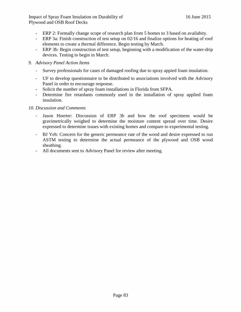
Impact of Spray Foam Insulation on Durability of
Plywood and OSB Roof Decks
16 June 2015
Page 83
- ERP 2: Formally change scope of research plan from 5 homes to 3 based on availabity.
- ERP 3a: Finish construction of test setup on 02/16 and finalize options for heating of roof
elements to create a thermal difference. Begin testing by March.
- ERP 3b: Begin construction of test setup, beginning with a modification of the water-drip
devices. Testing to begin in March.
9. Advisory Panel Action Items
- Survey professionals for cases of damaged roofing due to spray appied foam insulation.
- UF to develop questionnaire to be distributed to associations involved with the Advisory
Panel in order to encourage response.
- Solicit the number of spray foam installations in Florida from SFPA.
- Determine fire retardants commonly used in the installation of spray applied foam
insulation.
10. Discussion and Comments
- Jason Hoerter: Discussion of ERP 3b and how the roof specimens would be
gravimetrically weighed to determine the moisture content spread over time. Desire
expressed to determine issues with existing homes and compare to experimental testing.
- BJ Yeh: Concern for the generic permeance rate of the wood and desire expressed to run
ASTM testing to determine the actual permeance of the plywood and OSB wood
sheathing.
- All documents sent to Advisory Panel for review after meeting.

Impact of Spray Foam Insulation on Durability of
Plywood and OSB Roof Decks
16 June 2015
Page 84
C. Reviewed Literature
A full list of the literature reviewed as part of the State of the Art Literature Review can be
seen below. A pdf copy of each paper can be accessed here
https://www.dropbox.com/sh/7r66p2m7fslfrgf/AAD4E-felyk2kO11_tAhcHjTa?dl=0.
Index First Author Year Title
1 Saber 2010 3d thermal model for predicting thermal resistance of SPF wall assemblies
2 Bomberg-
Lstiburek 1998 Spray Polyurethane foam in external envelopes of buildings
3 Booth 2002 Foam insulation in low sloped roofing systems
4 Carll 2009 Moisture related properties of wood
5 Datin 2011 Wind uplift capacity of residential wood
6 Derome 2000 Large scale testing of two flat roof assemblies insulated with cellulose
7 Hendron 2002 Thermal performance of unvented attics in hot dry climates
8 Huang 2014 Health effects associated with faulty application of spray polyurethane foam in
residential homes
9 Jerman 2012 Effect of Moisture content on heat and moisture
10 Lstiburek 2008 Moisture control for buildings
11 Lstiburek 1993 Humidity Control in the humid south
12 Parker 2005 Literature review of the impact and need for attic ventilation in Florida homes
13 Prevatt 2014 Wind uplift capacity of foam retrofitted roof sheathing panels subjected to
rainwater intrusion
14 Rudd 2008 Lstiburek
15 Smits 1994 Effect of cellsize reduction on polyurethane foam physical properties
16 Timusk 2008 An investigation of the moisture sorption and permeability properties of mill
fabricated OSB
17 Trechsel 1985 Moisture in buildings-An Overview
18 Wu 2012 Rheology Study in Polyurethane rigid foams
19 Zabel-Morrell 1992 Wood Microbiology-decay and its prevention
20 Salonvaara 2013 Moisture Performance of sealed attics in climate zones 1 to 4
21 Gates 2013 Analysis and initial results of cold climate wood framed home retrofit
22 Dickson 2013 Guide to closing and conditioning ventilated crawlspaces
23 Lukachko 2013 Hybrid wall construction and quality control issues in Wyandotte Michigan
24 Zoeller 2013 Retrofitting the southeast the Cool Energy House
25 Pallin 2013 A hygrothermal risk analysis applied to residential unvented attics
26 Mayer 2014 Finite Element thermal modeling and correlation of various building wall
assembly systems
27 Puttagunta 2013 Performance House A Cold Climate Challenge Home
28 Walker 2013 An Assessment of envelope measures in mild climate deep energy retrofits
29 Morse-Fortier 2012 Potential Problems Arising from composite foam panels
30 Dixon 2012 Investigation of the Wind Resistance of Asphalt Shingles
31 Badiu 2013 Researches regarding the causes of degradation of roof systems
32 Ojanen 2000 Sealed cold roof and energy

Impact of Spray Foam Insulation on Durability of
Plywood and OSB Roof Decks
16 June 2015
Page 85
33 Straube 2010 EE12-4 Moisture-Safe Unvented Wood Roof Systems
34 Grin 2012 Moisture and structural analysis for high performance hybrid wall assemblies
35 Alturkistani 2008 A new test method to determine relative drying capacity...
36 Grin 2013 Application of Spray Foam Insulation Under Plywood and OSB roof
sheathing
37 Oustad 2005 Calculation of Moisture and Heat Transfer in Compact Roofs and Comparison
with Experimental data
38 Lstiburek 2014 Cool Hand Luke Meets Attics
39 Prevatt 2010 Field evaluation of thermal performance and energy efficiency of ccSPF
retrofitted vented residential attic
40 Sorahan 1993 Mortality and cancer morbidity of production works in the UK flexible
polyurethane foam industry
41 Lesage 2007 Airborne (MDI) Concentrations associated with the application of SPF in
residential construction
42 Mcbride 2011 UF-thesis WIND UPLIFT PERFORMANCE OF CCSPF-RETROFITTED
ROOF SHEATHING SUBJECTED TO WATER LEAKAGE
43 Shreyans 2011 UF-thesis THERMAL PERFORMANCE OF FOAM RETROFITTED
VENTED RESIDENTIAL ATTIC
44 DOE 2012 Application of Spray foam insulation under plywood and OSB sheathing
45 Nelson 2009 Compact Asphalt Shingle Roof systems - Should they be vented?
46 Honeywell N/A Energy Performance and Closed-Cell Spray Foam A Better Building
Technology
47 Owens-
Corning N/A Insulate with Integrity
48 Yuan et al 2010 Hygrothermal performance of wood-framed wall systems using spray
polyurethane foam
49 Parker 2002 Comparative Evaluation of the Impact of Roofing Systems on Residential
Cooling Energy Demand in Florida
50 Straube 2010 Building America Special Research Project - High R-Value Enclosures for
High Performance Residential Buildings in all climate zones
51 EPA 2012 Vacate and Safe Re-Entry Time
52 Shafer 2013 Spray Foam Basics for the Fire Service
53 Smegal 2013 Hygric Redistribution in insulated assemblies- retrofitting residential
envelopes without creating moisture issues
54 DIPS 2013 Sealed Attic System
55 Centex N/A What happens with a roof leak and spray foam
56 BASF 2011 Guidelines Reoccupancy Guidelines
57 Holladay 2014 Open-Cell Spray Foam and Damp Roof Sheathing
58 Bailes 2014 Does open cell spray foam really rot roofs
59 APA 2009 Water vaper permeance of wood structural panels
60 APA 2011 Wood moisture content and the importance of drying in wood building
systems
61 Schumacher 2008 Hygrothermal Performance of Insulated Sloped Wood-framed Roof
Assemblies
62 CASMA 2015 Technical Bulletin HOT ROOF DESIGNS
63 Santos N/A Solving the Air Barrier Riddle - Permeable or impermeable
64 Hubbs 2003 Building Envelope Performance Monitoring
65 Icynene N/A Open Cell Spray Foam
66 Building 2008 Unvented Roofs Hot Humid Climates and Asphalt Roofing Shingles
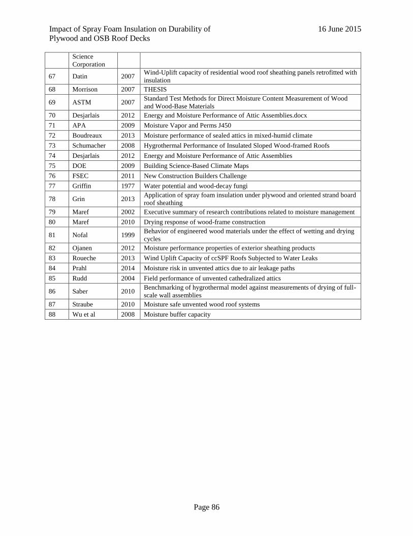
Impact of Spray Foam Insulation on Durability of
Plywood and OSB Roof Decks
16 June 2015
Page 86
Science
Corporation
67 Datin 2007 Wind-Uplift capacity of residential wood roof sheathing panels retrofitted with
insulation
68 Morrison 2007 THESIS
69 ASTM 2007 Standard Test Methods for Direct Moisture Content Measurement of Wood
and Wood-Base Materials
70 Desjarlais 2012 Energy and Moisture Performance of Attic Assemblies.docx
71 APA 2009 Moisture Vapor and Perms J450
72 Boudreaux 2013 Moisture performance of sealed attics in mixed-humid climate
73 Schumacher 2008 Hygrothermal Performance of Insulated Sloped Wood-framed Roofs
74 Desjarlais 2012 Energy and Moisture Performance of Attic Assemblies
75 DOE 2009 Building Science-Based Climate Maps
76 FSEC 2011 New Construction Builders Challenge
77 Griffin 1977 Water potential and wood-decay fungi
78 Grin 2013 Application of spray foam insulation under plywood and oriented strand board
roof sheathing
79 Maref 2002 Executive summary of research contributions related to moisture management
80 Maref 2010 Drying response of wood-frame construction
81 Nofal 1999 Behavior of engineered wood materials under the effect of wetting and drying
cycles
82 Ojanen 2012 Moisture performance properties of exterior sheathing products
83 Roueche 2013 Wind Uplift Capacity of ccSPF Roofs Subjected to Water Leaks
84 Prahl 2014 Moisture risk in unvented attics due to air leakage paths
85 Rudd 2004 Field performance of unvented cathedralized attics
86 Saber 2010 Benchmarking of hygrothermal model against measurements of drying of full-
scale wall assemblies
87 Straube 2010 Moisture safe unvented wood roof systems
88 Wu et al 2008 Moisture buffer capacity

Impact of Spray Foam Insulation on Durability of
Plywood and OSB Roof Decks
16 June 2015
Page 87
D. ERP 3A Data

Impact of Spray Foam Insulation on Durability of
Plywood and OSB Roof Decks
16 June 2015
Page 88
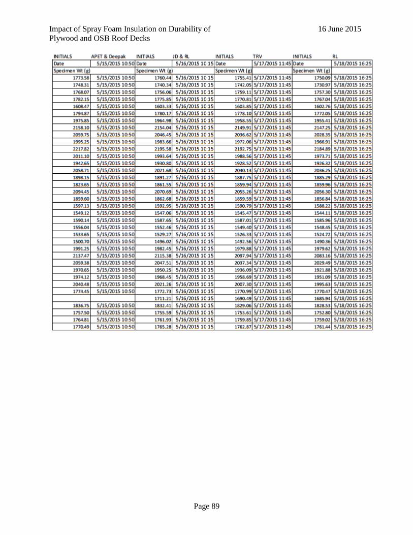
Impact of Spray Foam Insulation on Durability of
Plywood and OSB Roof Decks
16 June 2015
Page 89

Impact of Spray Foam Insulation on Durability of
Plywood and OSB Roof Decks
16 June 2015
Page 90

Impact of Spray Foam Insulation on Durability of
Plywood and OSB Roof Decks
16 June 2015
Page 91

Impact of Spray Foam Insulation on Durability of
Plywood and OSB Roof Decks
16 June 2015
Page 92

Impact of Spray Foam Insulation on Durability of
Plywood and OSB Roof Decks
16 June 2015
Page 93

Impact of Spray Foam Insulation on Durability of
Plywood and OSB Roof Decks
16 June 2015
Page 94