dr. peter paplewski, dipl. chem. product manager, · pdf filedr. peter paplewski, dipl. chem....
TRANSCRIPT
Benelux Scientific Technology Days Ghent, May 6th 2015
Dr. Peter Paplewski, Dipl. Chem.
Product Manager, CS/ONH-Analyzers, Kalkar, Germany
eMail: [email protected]
May 6, 2015
May 6, 2015 2
Bruker Elemental CS, ONH, dH Analyzers
Fundamentals, Overview & Applications (Do’s & Don’ts) of CS & ONH Analysis (by Combustion & IGF)
1. Carbon & Sulfur by combustion (induction furnace) 1. Introduction & Principles 2. Related Standards & Norms 3. Sulfur recovery & moisture, flowpath inertness
4. Possible Difficulties (in general) 5. Tips
2. ONH by Inert Gas Fusion 1. Principles of IGF 2. The Chemistry behind IGF: possible side reactions and how to
avoid them 3. IGF related Standards & Norms

May 6, 2015 3
Bruker Elemental CS, ONH, dH Analyzers
Fundamentals, Overview & Applications (Do’s & Don’ts) of CS & ONH Analysis (by Combustion & IGF)
2. ONH by Inert Gas Fusion
…continued… 4. Some “special” Applications:
a) ON in Al samples b) ONH in Ti c) H in high purity Al d) Ar in HIP samples by MS
5. Carrier gas selection

May 6, 2015 4
1. Carbon & Sulfur by Combustion Facts about Sulfur
Sulfur
• Occurs in elemental form, as sulfidic minerals/ores (e.g. FeS2, PbS, ZnS) and sulfate minerals
• Sulfur is an essential element for all life (e.g. amino acids) and present in coal, crude oil and other organic metabolites
• Burning of coal, coke and petroleum sets free large amounts of SO2 and in presence of water & oxygen, SO3. These react further to sulfurous acid (H2SO3) and sulfuric acid (H2SO3) “acid rain”
• Sulfur is a strong poison to catalysts and highly unwanted in most intermediate & final products. Environmental restrictions for the emission of sulfur compounds are getting lower every few years.
May 6, 2015 5
1. Carbon & Sulfur by Combustion Why Carbon and Sulfur?
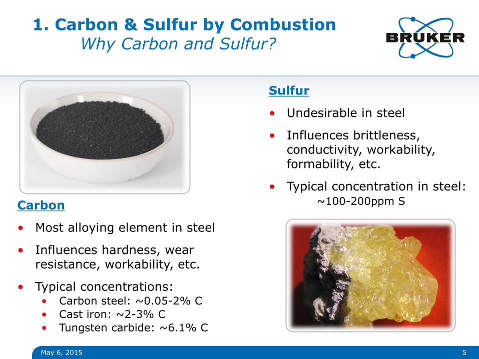
Carbon
• Most alloying element in steel
• Influences hardness, wear resistance, workability, etc.
• Typical concentrations: • Carbon steel: ~0.05-2% C
• Cast iron: ~2-3% C
• Tungsten carbide: ~6.1% C
Sulfur
• Undesirable in steel
• Influences brittleness, conductivity, workability, formability, etc.
• Typical concentration in steel: ~100-200ppm S

May 6, 2015
1. Carbon & Sulfur by Combustion 1. Operation Principle
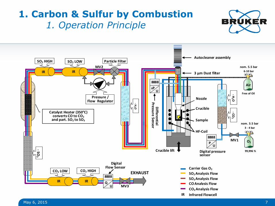
• Simultaneous determination of carbon and sulfur by combustion of a solid sample in a ceramic crucible within a pressurized oxygen flow in a high frequency induction furnace (under presence of a conductive accelerator).
• Transport of the formed CO2 and SO2 with the carrier gas oxygen through selective NDIR detectors
• Integration of the signals and calculation of results
6
O2 + {C} D
O2 in excess CO2 (+ CO)
Mn{Cx,Sy}m n M + m{x C + y S} D
O2 + {S} D
O2 in excess SO2 (…but…)
350 °C
Pt cat., O2
CO2
350 °C
Pt cat., O2
SO2 + SO3
order of detection matters: SO2 first, then CO2
1. Carbon & Sulfur by Combustion 1. Operation Principle
May 6, 2015 7
- H2 O
Particle Filter SO2 LOW SO2 HIGH
IR IR
O2
Air
- SO
3
CO2 LOW CO2 HIGH
IR IR
EXHAUST Carrier Gas O2
SO2 Analysis Flow
CO2 Analysis Flow
Infrared Flowcell IR
- H2 O
- C
O2
HF-Coil
Crucible
Sample
Nozzle
Digital Flow Sensor
8888
Q U
Pressure / Flow Regulator
MV1
MV2
MV3
3 - 4 bar
99,996 %
6-10 bar
Free of Oil
SO3 Analysis Flow
CO Analysis Flow
Catalyst Heater (350°C) converts CO to CO2
and part. SO2 to SO3
3 μm Dust filter
nom. 5.5 bar
nom. 3.5 bar
Autocleaner assembly
Diffe
ren
tial P
ressu
re Sen
sor
8888
ΔP U
8888
P U
Digital pressure sensor
Crucible lift
May 6, 2015
1. Carbon & Sulfur by Combustion 1. Operation Principle: Reagents
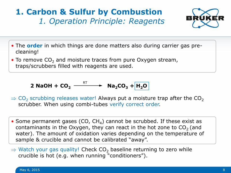
• The order in which things are done matters also during carrier gas pre-cleaning!
• To remove CO2 and moisture traces from pure Oxygen stream, traps/scrubbers filled with reagents are used.
8
2 NaOH + CO2 Na2CO3 + H2O RT
CO2 scrubbing releases water! Always put a moisture trap after the CO2 scrubber. When using combi-tubes verify correct order.
• Some permanent gases (CO, CH4) cannot be scrubbed. If these exist as contaminants in the Oxygen, they can react in the hot zone to CO2 (and water). The amount of oxidation varies depending on the temperature of sample & crucible and cannot be calibrated “away”.
Watch your gas quality! Check CO2 baseline returning to zero while crucible is hot (e.g. when running “conditioners”).
1. Carbon & Sulfur by Combustion 1. Operation Principle: HF-Generator
May 6, 2015 9
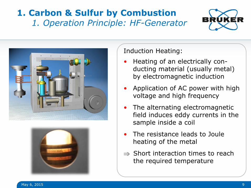
Induction Heating:
• Heating of an electrically con-ducting material (usually metal) by electromagnetic induction
• Application of AC power with high voltage and high frequency
• The alternating electromagnetic field induces eddy currents in the sample inside a coil
• The resistance leads to Joule heating of the metal
Short interaction times to reach the required temperature
May 6, 2015 10
1. Carbon & Sulfur by Induction Accelerators I
Why do we need “accelerators” at all?
• Accelerators are a conductive metal and needed to provide a “handle” (an interaction coupling) to the HF field coming from the HF-generator. Otherwise nothing will happen with a non-conductive sample.
• Another purpose of the accelerator is to ignite or “set fire” to the sample. The combustion of the accelerators used is exothermic what means it sets free additional energy.
• Accelerators can also double as a flux to dissolve oxide skins and make the melt thoroughly fluid.
Note: A completely fluid melt is essential in order to oxidize the carbon and sulfur in the sample in a short time.
ALWAYS watch your melt and follow the “one cannot find too much” rule

May 6, 2015 11
1. Carbon & Sulfur by Induction Accelerators II
• Tungsten Good general purpose accelerator for plain carbon steels providing excellent combustion characteristics when combined with tin.
• Tin Typically used as an additive to tungsten, copper and iron. Burns readily, producing a lot of heat. It can lower the liquefaction temperature of the melt, acting as a flux.
• Iron chip Used for both carbon and sulfur determination in some ferroalloys as well as nonferrous materials. Usually combined with tungsten or tin.
• Copper chip Excellent accelerator/flux for carbon determination (particularly in ultra low carbon determination) in steel, nonferrous metals and alloys. Usually combined with iron chip when nonferrous materials are analyzed. Copper accelerator is normally not recommended for sulfur determination in ferrous materials.
1. Carbon & Sulfur by Induction Principle of a NDIR Detector
May 6, 2015 12
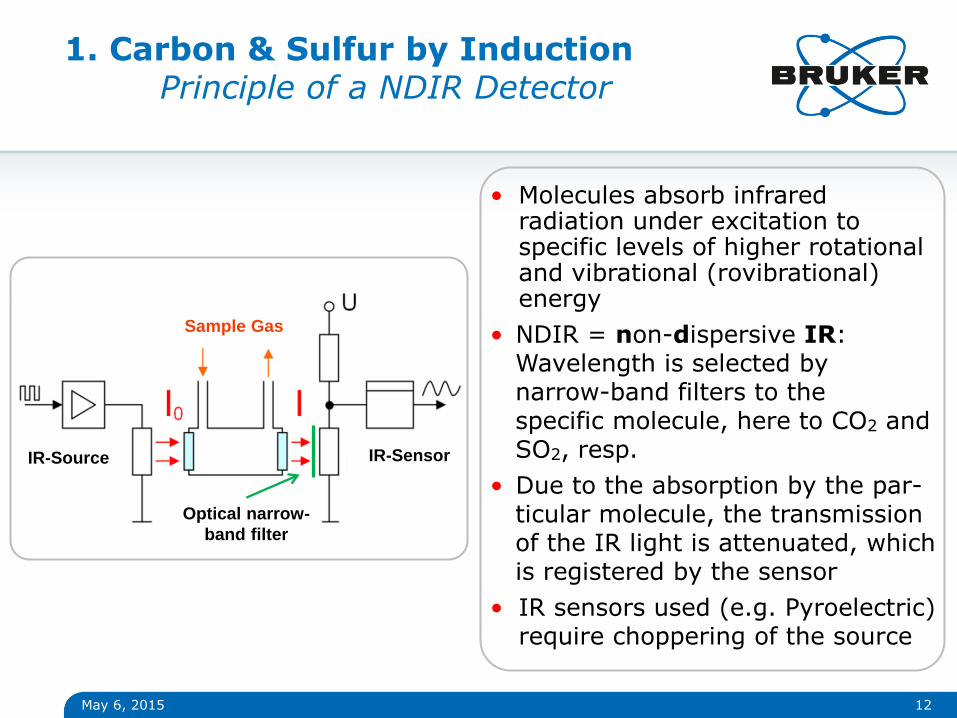
Sample Gas
IR-Source IR-Sensor
• Molecules absorb infrared radiation under excitation to specific levels of higher rotational and vibrational (rovibrational) energy
• NDIR = non-dispersive IR: Wavelength is selected by narrow-band filters to the specific molecule, here to CO2 and SO2, resp.
• Due to the absorption by the par- ticular molecule, the transmission of the IR light is attenuated, which is registered by the sensor
• IR sensors used (e.g. Pyroelectric) require choppering of the source
Optical narrow-
band filter
May 6, 2015 13
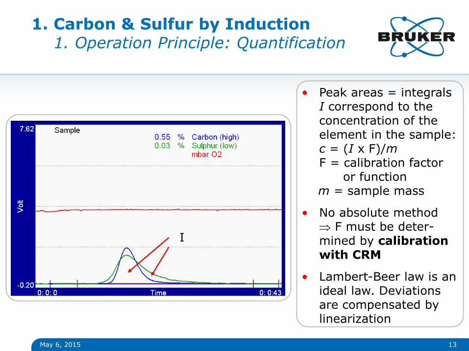
1. Carbon & Sulfur by Induction 1. Operation Principle: Quantification
• Peak areas = integrals I correspond to the concentration of the element in the sample: c = (I x F)/m F = calibration factor
or function m = sample mass
• No absolute method F must be deter-mined by calibration with CRM
• Lambert-Beer law is an ideal law. Deviations are compensated by linearization
I

1. Carbon & Sulfur by Induction 2. Applications
May 6, 2015 14
Applications
Metals ● Steel, cast iron ● Copper, brass ● Iron, nickel, cobalt alloys ● Ferroalloys ● Titanium and alloys ● Zirconium and alloys ● Tungsten and alloys ● Precious metals
Minerals ● Lime, limestone, gypsum ● Cement ● Ceramics
Markets
● Aerospace ● Automotive ● Casting ● Ceramics and cement industry ● Chemical plants and refineries ● Contract laboratories ● Marie and military ● Research labs, universities
Primary-metal production industry ● Steel, iron, copper, etc. ● Foundries
Metal processing and machining industry ● Forging plants ● Rolling mills
May 6, 2015 15
1. Carbon & Sulfur by Induction 2. Related Standards/Norms I
• ASTM E 1019 Standard Test Methods for Determination of Carbon, Sulfur, Nitrogen and Oxygen in Steel and in Iron, Nickel, and Cobalt Alloys
• ASTM E 1587 Standard Test Methods for Chemical Analysis of Refined Nickel
• ASTM G 79 Standard Practice for Evaluation of Metals Exposed to Carburization Environments
• ASTM C 1494 Standard Test Methods for Determination of Mass Fraction of Carbon, Nitrogen, and Oxygen in Silicon Nitride Powder
• ASTM E 1941 Standard Test Method for Determination of Carbon in Refractory and Reactive Metals and their Alloys
• ASTM E 1915 Standard Test Methods for Analysis of Metal Bearing Ores and Related Materials by Combustion Infrared Absorption Spectrometry
•
May 6, 2015 16
1. Carbon & Sulfur by Induction 2. Related Standards/Norms II
• ASTM D 1552 Standard Test Method for Sulfur in Petroleum Products (High-Temperature Method)
• ASTM C 25 Std. Test Methods for Chemical Analysis of Limestone, Quicklime and Hydrated Lime
• ASTM C 1408 Standard Test Method for Carbon (Total) in Uranium Oxide Powders and Pellets By Direct Combustion-Infrared Detection Method
• UOP 703 Carbon on Catalysts by Induction Furnace Combustion and Infrared Detection
as well as many ISO Methologies
• Carbon: ISO 9556 (steel & iron), 10694 (soil), 10719 (steels & iron), 21614 ([U, Gd]O2, [U, Pu]O2), 9891 (UO2), 15349-2 (unalloyed steel)
• Sulfur: ISO 4935 (steel & iron), 13902 (steel &iron), 4689 (iron ores), 7524, 7526 (Ni, Ni alloys, Fe-Ni), 15350 (steel & iron: C&S)

May 6, 2015 17
1. Carbon & Sulfur by Induction 3. Sulfur Recovery & Water
SO2 losses do often occur after the combustion
• In combination with moisture SO2 forms highly corrosive species, that tend to stick “on the wall” and thus retard or retain SO2 delivery to the detectors. Possible sources of moisture are:
• Carrier gas (e.g. medical grade Oxygen); the capacity of the build-in pre-cleaning is limited
• Organic matter present in the sample (or carrier gas) that combust to CO2 and H2O
• Non dried samples or samples that contain Hydroxides or Hydrides (minerals, (hydrated) lime, etc.) or samples that contain water in form of crystal water will release high amounts of water during combustion
• Ambient Air Humidity: Especially when the analyzer is “cold” or during breaks Close the furnace and use standby mode. Active heating of the dust filter over the dwell point helps to overcome pause effects.

May 6, 2015 18
1. Carbon & Sulfur by Induction 3. Sulfur Recovery & Inertness
How to overcome or minimize Sulfur Recovery Problems?
• Verify chemical inertness of the entire analytical flow path! Prefer PFA (or PTFE) lines over stainless steel (high Mn) lines for the analysis gases.
• Remove moisture immediately, check moisture scrubber if in doubt.
• When running samples like limestone, minerals and Hydroxides, … use a build-in membrane dryer (Nafion™ polymer) directly after the furnace. This dramatically improves Sulfur on this samples (and reduces moisture scrubber consumption with no add. operation costs)
May 6, 2015 19
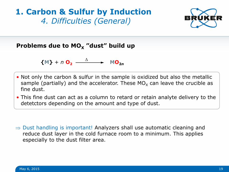
1. Carbon & Sulfur by Induction 4. Difficulties (General)
Problems due to MOX ”dust” build up
• Not only the carbon & sulfur in the sample is oxidized but also the metallic sample (partially) and the accelerator. These MOX can leave the crucible as fine dust.
• This fine dust can act as a column to retard or retain analyte delivery to the detetctors depending on the amount and type of dust.
{M} + n O2 MO2n
D
Dust handling is important! Analyzers shall use automatic cleaning and reduce dust layer in the cold furnace room to a minimum. This applies especially to the dust filter area.
May 6, 2015 20
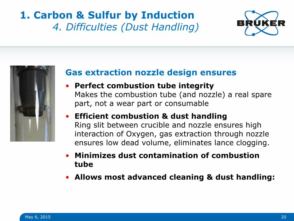
Gas extraction nozzle design ensures
• Perfect combustion tube integrity Makes the combustion tube (and nozzle) a real spare part, not a wear part or consumable
• Efficient combustion & dust handling Ring slit between crucible and nozzle ensures high interaction of Oxygen, gas extraction through nozzle ensures low dead volume, eliminates lance clogging.
• Minimizes dust contamination of combustion tube
• Allows most advanced cleaning & dust handling:
1. Carbon & Sulfur by Induction 4. Difficulties (Dust Handling)
May 6, 2015 21
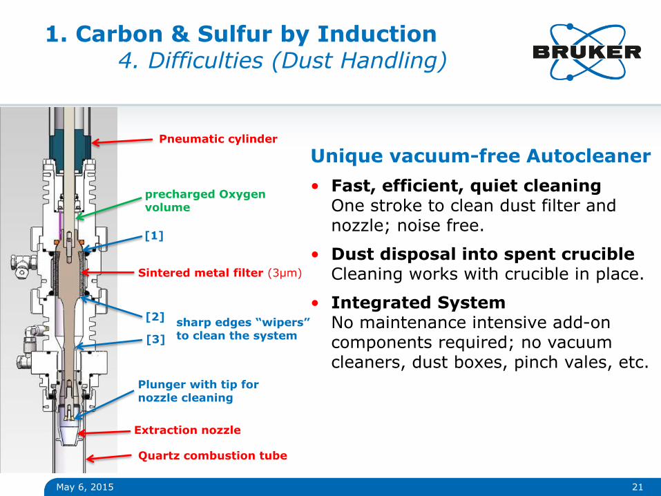
Unique vacuum-free Autocleaner
• Fast, efficient, quiet cleaning One stroke to clean dust filter and nozzle; noise free.
• Dust disposal into spent crucible Cleaning works with crucible in place.
• Integrated System No maintenance intensive add-on components required; no vacuum cleaners, dust boxes, pinch vales, etc.
Pneumatic cylinder
Sintered metal filter (3µm)
Extraction nozzle
Quartz combustion tube
Plunger with tip for nozzle cleaning
[1]
[2]
[3]
sharp edges “wipers” to clean the system
precharged Oxygen volume
1. Carbon & Sulfur by Induction 4. Difficulties (Dust Handling)

May 6, 2015 22
1. Carbon & Sulfur by Induction 4. Difficulties (General)
Some MOX are known to interact with SO2
• Certain metals and their oxides are known to create sulfur recovery problems. These include:
Mn, Cu, Sn, Pb, Pt, Ir, Pd Although the exact reasons are unknown, two possible reasons exist:
1. Absorption/scrubbing of SO2 (by MnO2, PbO2, CuO, …) will happen generally in the cold zone of the furnace (dust filter, combustion tube, etc.) by the dust produced during combustion
Possible check with porous crucible covers
2. Catalytic Oxidation of SO2 to SO3 will happen in the hot zone (crucible itself)
Possible check by adding material to a CRM
May 6, 2015 23
1. Carbon & Sulfur by Induction 5. Tips
• Light particles might be partially drawn away by a high lance or purge flow. Check by weighing back the crucible (without combusting). If a problem (showing up in C&S) either use capsules or cover powder by a layer of quartz sand.
• Very little sample mass with non-conductive material can also represent a problem (not enough melt to be homogeneous) use quartz sand
• Sn accelerator even when used in combination reduces the SO2 response factor (compared to W, Fe). It is stable but you need other S-calibration
• Cu accelerator is the preferred accelerator for “carbon only” analysis. Manual cleaning of any CuO is required before measuring low S again.
• What channel (C, S or both) is affected? when trouble shooting - always - ask yourself this question …
May 6, 2015 24
1. Carbon & Sulfur by Induction 5. Tips
• Problems related only to Carbon are most likely due to residual carbon in the consumables (crucible, accelerator, gas) or contaminations in the system (e.g. silicon grease) bake out the system while watching carbon baseline. Sometimes a different blank due to different sample mass (and therefore heat to the crucible) can conrtribute
• Problems related only to Sulfur are most likely due to moisture or dust. Check gas & sample for moisture; verify moisture scrubber is fresh, use membrane dryer. Check for dust build up and clean. Check sample for sulfur recovery problems (e.g. Cu)
• Problems related to both check for leaks and losses of samples. If not successful call service (and report your findings)
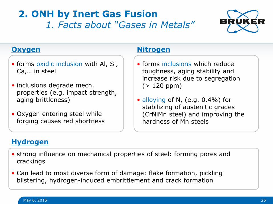
Oxygen
• forms oxidic inclusion with Al, Si, Ca,… in steel
• inclusions degrade mech. properties (e.g. impact strength, aging brittleness)
• Oxygen entering steel while forging causes red shortness
May 6, 2015 25
Nitrogen
• forms inclusions which reduce toughness, aging stability and increase risk due to segregation (> 120 ppm)
• alloying of N, (e.g. 0.4%) for stabilizing of austenitic grades (CrNiMn steel) and improving the hardness of Mn steels
Hydrogen
• strong influence on mechanical properties of steel: forming pores and crackings
• Can lead to most diverse form of damage: flake formation, pickling blistering, hydrogen-induced embrittlement and crack formation
2. ONH by Inert Gas Fusion 1. Facts about “Gases in Metals”

May 6, 2015 26
The Principle: Inert Gas Fusion Method
• Also referred to as Gas Fusion Analysis (GFA) or Carrier Gas Hot Extraction (CGHE) methods.
• Sample is fused in a high-purity graphite crucible at temperatures up to 3000 ºC
• Oxygen reacts with Carbon (from graphite) to CO and will be measured with IR-Cells
• Nitrogen appears as N2 and will be measured with TC-cell
• Hydrogen appears as H2 and will be measured with TC-cell
• Thermal conductivity: He/H2 and N2/Ar have similar TC. Thus N2 or Ar is used for determination of Hydrogen; He for determination of Nitrogen
2. ONH by Inert Gas Fusion 1. Operation Principle

May 6, 2015 27
2. ONH by Inert Gas Fusion 1. Operation Principle
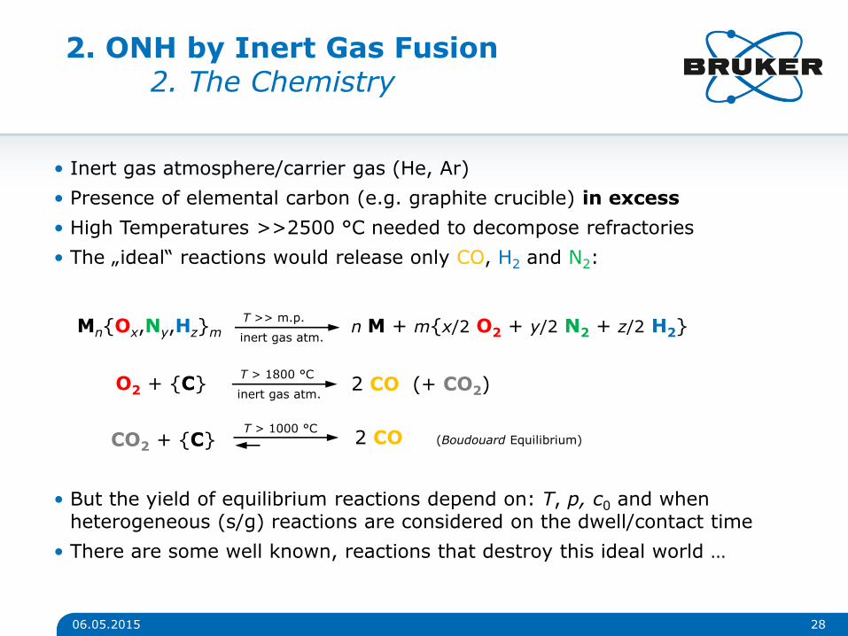
• Inert gas atmosphere/carrier gas (He, Ar)
• Presence of elemental carbon (e.g. graphite crucible) in excess
• High Temperatures >>2500 °C needed to decompose refractories
• The „ideal“ reactions would release only CO, H2 and N2:
06.05.2015 28
Mn{Ox,Ny,Hz}m T >> m.p.
inert gas atm. n M + m{x/2 O2 + y/2 N2 + z/2 H2}
O2 + {C} T > 1800 °C
inert gas atm. 2 CO (+ CO2)
• But the yield of equilibrium reactions depend on: T, p, c0 and when heterogeneous (s/g) reactions are considered on the dwell/contact time
• There are some well known, reactions that destroy this ideal world …
CO2 + {C} T > 1000 °C
2 CO (Boudouard Equilibrium)
2. ONH by Inert Gas Fusion 2. The Chemistry
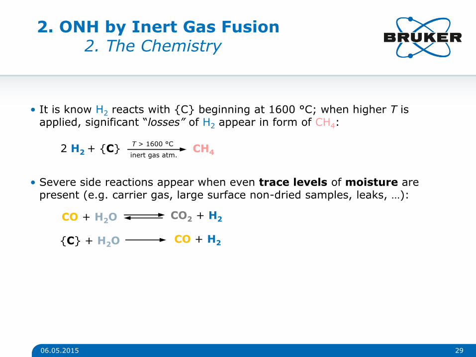
• It is know H2 reacts with {C} beginning at 1600 °C; when higher T is applied, significant “losses” of H2 appear in form of CH4:
06.05.2015 29
2 H2 + {C} T > 1600 °C
inert gas atm. CH4
• Severe side reactions appear when even trace levels of moisture are present (e.g. carrier gas, large surface non-dried samples, leaks, …):
CO + H2O CO2 + H2
{C} + H2O CO + H2
2. ONH by Inert Gas Fusion 2. The Chemistry

• If no stringent Temperature control is applied, the primary products of an IGF analysis are not only CO, N2 and H2 but also CO2 , CH4
• Hydrogen can appear as H2, CH4
• Oxidation of CH4 (from H2) to CO2 and H2O results in „false positive“ amounts of O (if O is determined via CO2) and losses of H2 if Hydrogen is only assessed as H2
• In the presence of H2O (moisture), the H & O determination problem is simply not solvable due to conversion reactions
06.05.2015 30
2. ONH by Inert Gas Fusion 2. The Chemistry

May 6, 2015 31
• ASTM E 1019 Standard Test Methods for Determination of Carbon, Sulfur, Nitrogen and Oxygen in Steel and in Iron, Nickel, and Cobalt Alloys
• ASTM E 2575 Standard Test Method for Determination of Oxygen in Copper and Copper Alloys
• ASTM E 1409 Standard Test Method for Determination of Oxygen and Nitrogen in Titanium and Titanium Alloys by the Inert Gas Fusion Technique
• ASTM E 1447 Standard Test Method for Determination of Hydrogen in Titanium and Titanium Alloys by the Inert Gas Fusion Thermal Conductivity Method
• ASTM E 1937 Standard Test Method for Determination of Nitrogen in Titanium and Titanium Alloys by the Inert Gas Fusion Technique
• ASTM E 1569 Standard Test Method for Determination of Oxygen in Tantalum Powder
2. ONH by Inert Gas Fusion 3. Related Standards

May 6, 2015 32
• ASTM E 1587 Standard Test Methods for Chemical Analysis of Refined Nickel
• ASTM E 2792 Standard Test Method for Determination of Hydrogen in Aluminum and Aluminum Alloys by Inert Gas Fusion
as well as many ISO Methologies
• Steel & Iron: ISO 10276-2, 10720, 15351, 17053
• Titanium: ISO 22963
• UO2, PuO2: ISO 25710
2. ONH by Inert Gas Fusion 2. Related Standard II
33
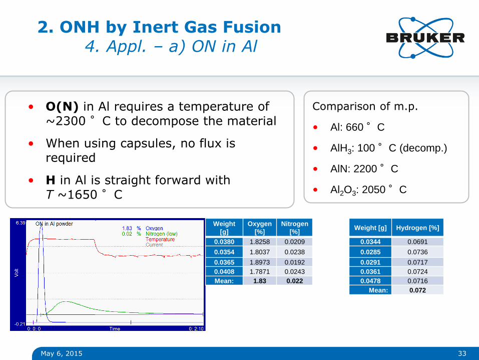
Comparison of m.p.
• Al: 660 °C
• AlH3: 100 °C (decomp.)
• AlN: 2200 °C
• Al2O3: 2050 °C
May 6, 2015
• O(N) in Al requires a temperature of ~2300 °C to decompose the material
• When using capsules, no flux is required
• H in Al is straight forward with T ~1650 °C
2. ONH by Inert Gas Fusion 4. Appl. – a) ON in Al
Weight
[g]
Oxygen
[%]
Nitrogen
[%]
0.0380 1.8258 0.0209
0.0354 1.8037 0.0238
0.0365 1.8973 0.0192
0.0408 1.7871 0.0243
Mean: 1.83 0.022
Weight [g] Hydrogen [%]
0.0344 0.0691
0.0285 0.0736
0.0291 0.0717
0.0361 0.0724
0.0478 0.0716
Mean: 0.072
34
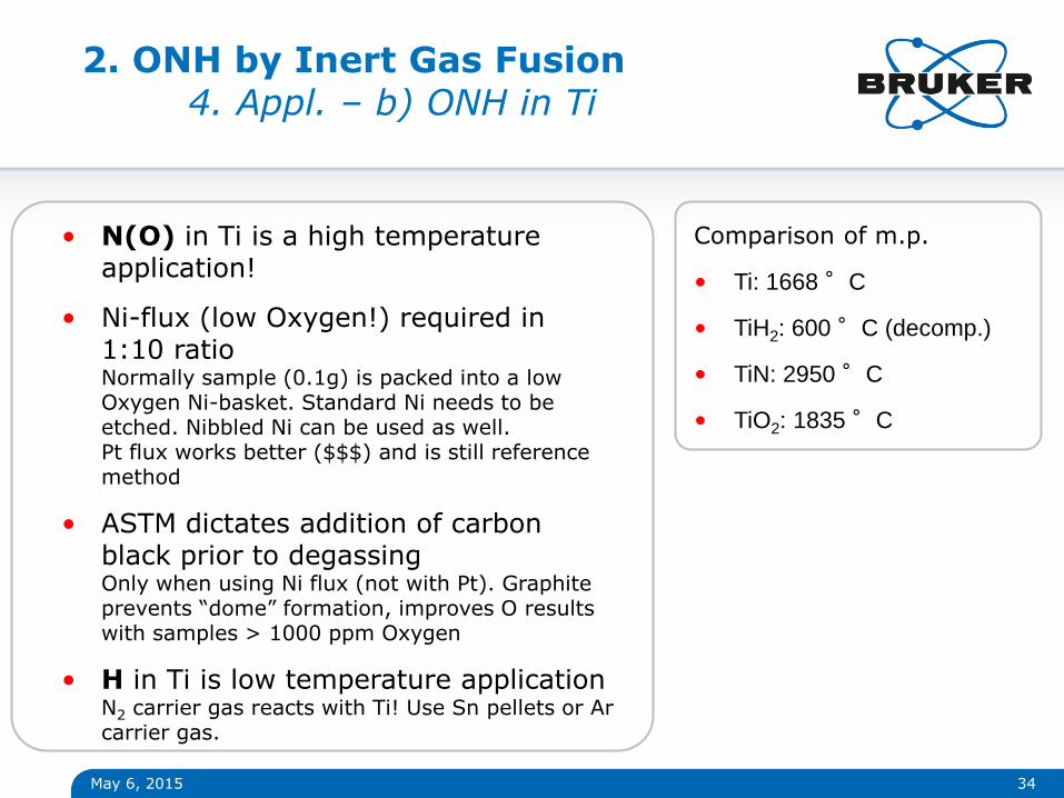
Comparison of m.p.
• Ti: 1668 °C
• TiH2: 600 °C (decomp.)
• TiN: 2950 °C
• TiO2: 1835 °C
May 6, 2015
• N(O) in Ti is a high temperature application!
• Ni-flux (low Oxygen!) required in 1:10 ratio Normally sample (0.1g) is packed into a low Oxygen Ni-basket. Standard Ni needs to be etched. Nibbled Ni can be used as well. Pt flux works better ($$$) and is still reference method
• ASTM dictates addition of carbon black prior to degassing Only when using Ni flux (not with Pt). Graphite prevents “dome” formation, improves O results with samples > 1000 ppm Oxygen
• H in Ti is low temperature application N2 carrier gas reacts with Ti! Use Sn pellets or Ar carrier gas.
2. ONH by Inert Gas Fusion 4. Appl. – b) ONH in Ti

Hydrogen in Aluminum Pore Formation
35
• In aluminum production and casting Hydrogen can lead to pore and crack formation
• With welding H2 dissociates in the arc into H + H (atomic).
• Liquid aluminum has a high solubility of atomic hydrogen
• When cooling down (liquid/solid) solubility of hydrogen decreases
• Solved H atoms in the lattice recombines to H2 molecules
• Hydrogen molecules escape from the melt as gas bubbles
• When gas bubbles are included with solidification, voids filled with H2–are formed: pores
REM-picture of a pore Source: Internet, MIG WELD, Landau
melting point
boiling point
Solubility, liquid state @ m.p.
Solubility, solid state @ m.p.
Solubility in the hot zone
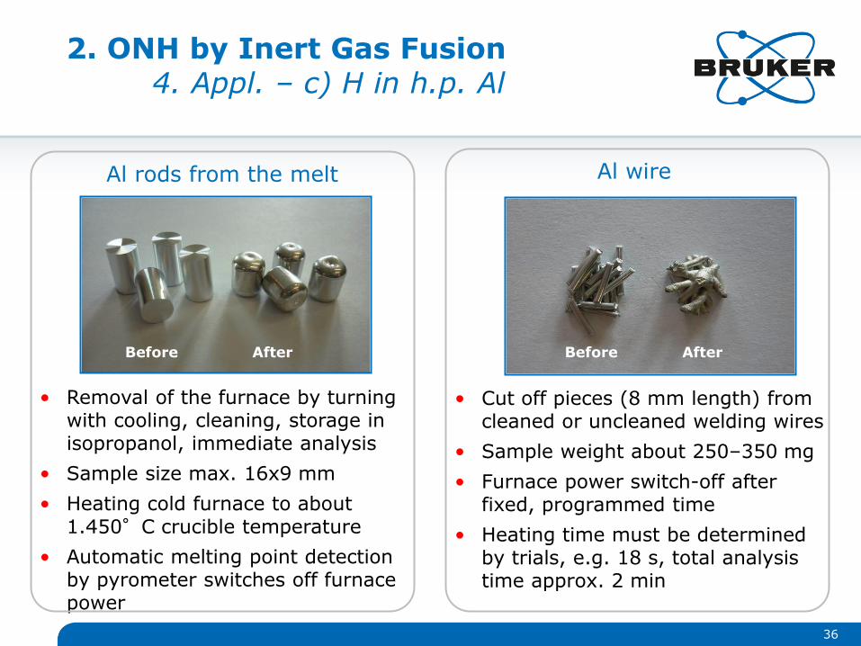
• Removal of the furnace by turning with cooling, cleaning, storage in isopropanol, immediate analysis
• Sample size max. 16x9 mm
• Heating cold furnace to about 1.450°C crucible temperature
• Automatic melting point detection by pyrometer switches off furnace power
36
Al rods from the melt
• Cut off pieces (8 mm length) from cleaned or uncleaned welding wires
• Sample weight about 250–350 mg
• Furnace power switch-off after fixed, programmed time
• Heating time must be determined by trials, e.g. 18 s, total analysis time approx. 2 min
Al wire
Before After Before After
2. ONH by Inert Gas Fusion 4. Appl. – c) H in h.p. Al

May 6, 2015 37
Extract from App Note AN1310 (see also ASTM E 2792-11)
Typical Results: #1: 0.319 (8) ppm, n = 10 #2: 0.059 (3) ppm, n = 10 #3: 0.163 (3) ppm, n = 5 #4: 0.264 (8) ppm, n = 5 #5: 0.050 (5) ppm, n = 5 One s STD in brackets
2. ONH by Inert Gas Fusion 4. Appl. – c) H in h.p. Al
May 6, 2015 38
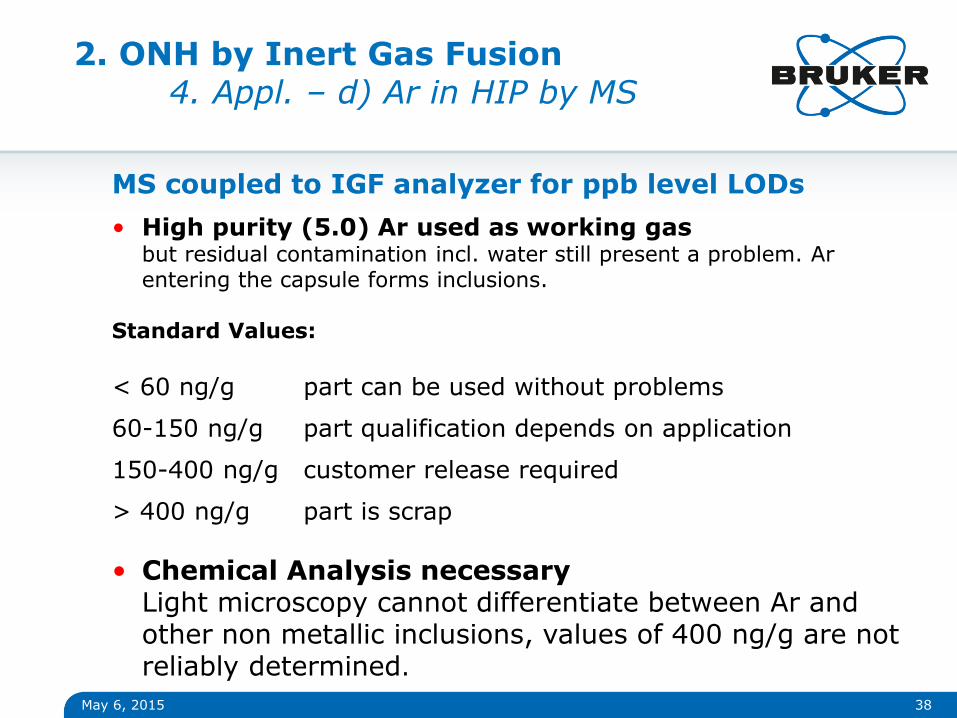
MS coupled to IGF analyzer for ppb level LODs
• High purity (5.0) Ar used as working gas but residual contamination incl. water still present a problem. Ar entering the capsule forms inclusions.
Standard Values:
< 60 ng/g part can be used without problems
60-150 ng/g part qualification depends on application
150-400 ng/g customer release required
> 400 ng/g part is scrap
• Chemical Analysis necessary Light microscopy cannot differentiate between Ar and other non metallic inclusions, values of 400 ng/g are not reliably determined.
2. ONH by Inert Gas Fusion 4. Appl. – d) Ar in HIP by MS
May 6, 2015 39
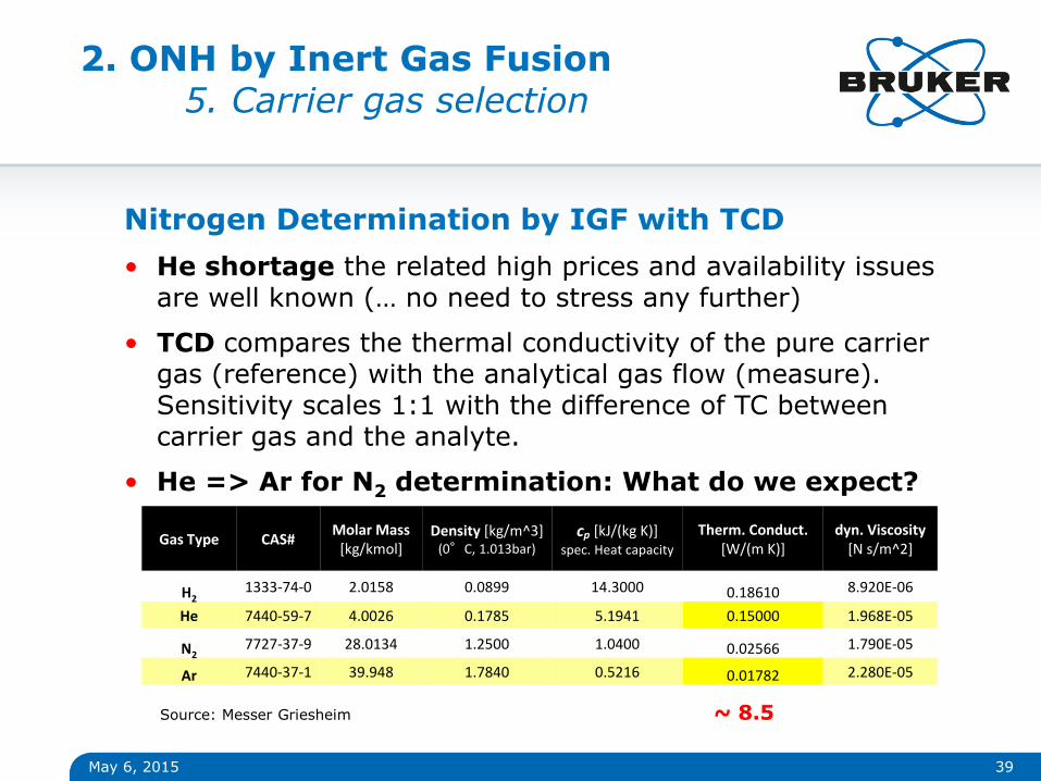
Nitrogen Determination by IGF with TCD
• He shortage the related high prices and availability issues are well known (… no need to stress any further)
• TCD compares the thermal conductivity of the pure carrier gas (reference) with the analytical gas flow (measure). Sensitivity scales 1:1 with the difference of TC between carrier gas and the analyte.
• He => Ar for N2 determination: What do we expect?
Gas Type CAS# Molar Mass
[kg/kmol] Density [kg/m^3]
(0°C, 1.013bar) cp [kJ/(kg K)]
spec. Heat capacity
Therm. Conduct. [W/(m K)]
dyn. Viscosity [N s/m^2]
H2 1333-74-0 2.0158 0.0899 14.3000 0.18610 8.920E-06
He 7440-59-7 4.0026 0.1785 5.1941 0.15000 1.968E-05
N2 7727-37-9 28.0134 1.2500 1.0400 0.02566 1.790E-05
Ar 7440-37-1 39.948 1.7840 0.5216 0.01782 2.280E-05
~ 8.5 Source: Messer Griesheim
2. ONH by Inert Gas Fusion 5. Carrier gas selection

May 6, 2015 40
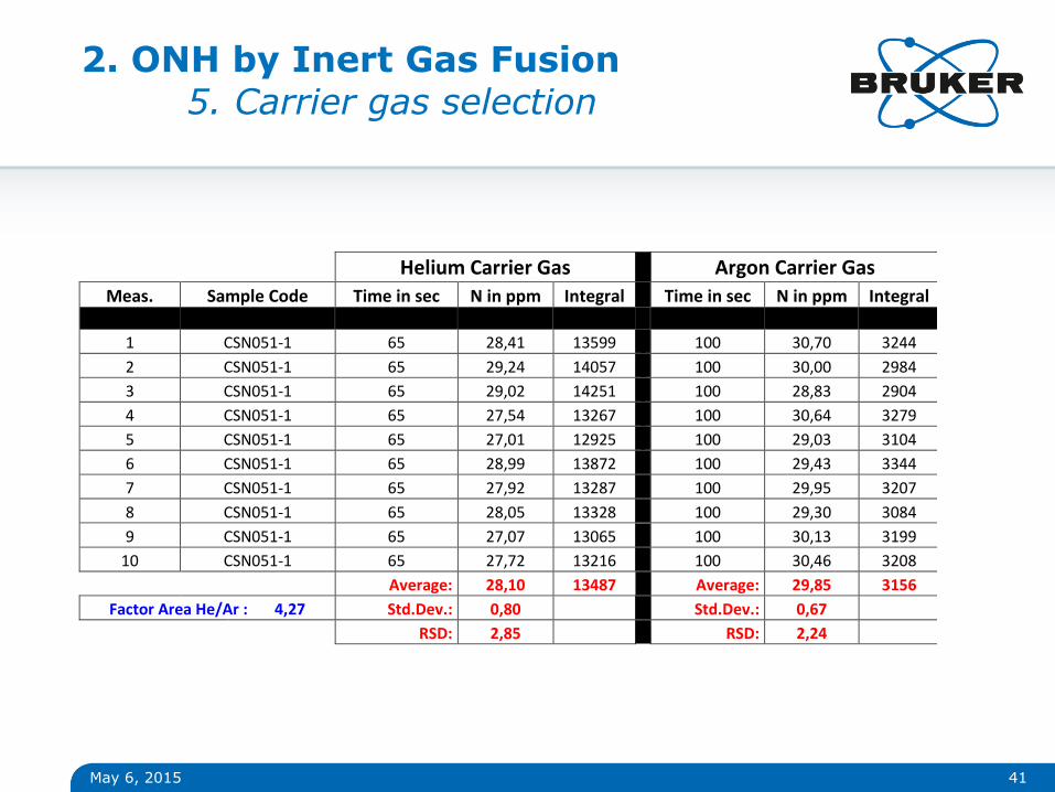
Nitrogen Determination by IGF with TCD using Ar
• He => Ar conversion: Penalty Comparing the 2 carrier gases: Ar has ~8.5 lower TC than He. But we are comparing two carrier gases. What matters is analyte vs. carrier gas:
DTC1: He – N2 = 0.1243 (DTC1/ DTC2) = -15.9
DTC2: Ar – N2 = -0.0078
• Recent TCD developments improved the stability for long measuring times, introduced on-the-fly programmable amplifiers and polarity switching.
• Real World performance He vs. Ar “out-of-the-box” (changed TCD amplification); 20-200 ppm N range, 1g & 0.5g sample
2. ONH by Inert Gas Fusion 5. Carrier gas selection
May 6, 2015 41
Helium Carrier Gas Argon Carrier Gas
Meas. Sample Code Time in sec N in ppm Integral Time in sec N in ppm Integral
1 CSN051-1 65 28,41 13599 100 30,70 3244
2 CSN051-1 65 29,24 14057 100 30,00 2984
3 CSN051-1 65 29,02 14251 100 28,83 2904
4 CSN051-1 65 27,54 13267 100 30,64 3279
5 CSN051-1 65 27,01 12925 100 29,03 3104
6 CSN051-1 65 28,99 13872 100 29,43 3344
7 CSN051-1 65 27,92 13287 100 29,95 3207
8 CSN051-1 65 28,05 13328 100 29,30 3084
9 CSN051-1 65 27,07 13065 100 30,13 3199
10 CSN051-1 65 27,72 13216 100 30,46 3208
Average: 28,10 13487 Average: 29,85 3156
Factor Area He/Ar : 4,27 Std.Dev.: 0,80 Std.Dev.: 0,67
RSD: 2,85 RSD: 2,24
2. ONH by Inert Gas Fusion 5. Carrier gas selection

May 6, 2015 42
Conclusion
• He => Ar conversion: Penalty? Changing the TCD gain on-the-fly reduces the “penalty factor“ from ~16 to ~4 without further modifications.
• Real world performance Allows reliable measurement of 20ppm N with 0.5g sample. Switching back to He possible any time. No additional modifications (~30s longer analysis times using Ar).
• Ready to run on Ar? Ar is good enough for 90% of all measurements in the steel industry, annual savings up to 60k€ possible.
2. ONH by Inert Gas Fusion 5. Carrier gas selection

www.bruker.com
© Copyright Bruker Corporation. All rights reserved.