dr. curran crawford & luke stack department of mechanical engineering university of victoria 28...
TRANSCRIPT

Dr. Curran Crawford & Luke StackDepartment of Mechanical EngineeringUniversity of Victoria
28th ASME Wind Energy Symposium47th AIAA Aerospace Sciences Meeting and ExhibitionJanuary 8, 2009
Optimal Rotors for Distributed Wind Turbines
1

Overview
•Why small wind turbines?–Why are they interesting academically?
•Design approach•Study results
2
There is wind out there if you’re careful where to look
•Wind resource–Studies of wind in urban areas
•Generally low mean wind speeds•Turbulence•Some viable locations– Purposeful building integration– Windy locales
–Remote locations•Open terrain•Higher energy costs
–Tower mounted preferable
3

The top of a 100m pole is always going have better wind, but...
•MW scale machines are hard to beat–Economies of scale–Wind shear
•kW scale machines left in the past?–MW lessons learnt not applied to small machines–Consumer demand
•Engagement with energy source
–Distributed energy source•Transmission infrastructure•Smart grids
4

There is unique academic value at the small scale
•Validation data & trying new ideas are easy–Design-build-test for low $
•Challenging design space–Strive for multi-objective, multi-disciplinary optimum
•Energy yield, cost, noise, etc.•Shape, structure, etc.•Matching generator to rotor
–Tools & methods applicable at all scales
5

And of course someone has pay the bills!
•Industrial sponsor–Ampair in UK–Redesigning & up-scaling product range
•100 W – 8 kW
–Some units left off results for commercial sensitivities
•UVic efforts –Focusing on rotor blade design–HAWTs not VAWTs
6

So, what’s different at the small scale?
•Reynolds number–Operating around transition
•Rotor control–Controlled pitching too expensive–Failsafe pitching possible (PTS or PTF)
•Generator–Cogging torque
•Startup wind speed
•Power electronics–Full power conversion–Passive or active generator torque control
7

Our approach to rotor optimization•A stepwise approach
8

BEM-based analysis tool ExcelBEM was used for analysis•Implementation
–Excel interface–Underlying C/Matlab code
•Enhanced BEM method–Coned rotors, including blade section sweep–Steady and unsteady aero
•Rigid body blade flapping
– Implicit optimal control algorithms•PTF, PTS, VSS
–Generator characteristics–Blade section structural properties & stresses–Low frequency noise
9
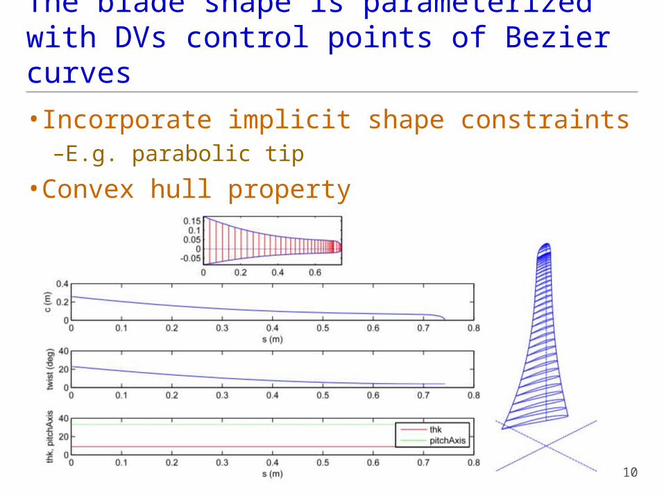
The blade shape is parameterized with DVs control points of Bezier curves
•Incorporate implicit shape constraints–E.g. parabolic tip
•Convex hull property
10

Blade section choice treated as a parameter
•Want to be confident in aerodynamic properties–Not much experimental data available!–Eppler & NACA 44XX–Flat plate extensions for full AOA range
•Structure–Glass/carbon thermoplastic skins (Twintex)–Foam core
11

The generator characteristic is a parameter
•Passive PE–Single torque-speed-power relationship
•Torque matching problem
–Over speed protection from centrifugal PTS–E.g. battery charging
•Active PE–Variable speed by varying generator load on rotor–Torque-speed-power surface–Need to find optimum operating profile on surface
•Variable efficiency–Not sufficient to find optimal tip-speed ratio
12

Generator and aerodynamic torque must be equal for passive PE
•Example of a bad match!
13

Two approaches to active PE optimization
•Implicit–Use built-in optimal operating routines in ExcelBEM–No extra DVs–Computationally intensive
•Require multiple BEM solutions for each design iterate
•Explicit–Add DVs for Ω at 15-20 wind speeds–Directly control rotor speeds–Extra finite differencing, but better overall
14
The overall optimization procedure was developed during the study•Full process only applied to final example
– Incremental steps for other design cases
•Final design/optimization process–Matlab driven interactive with designer–Navigate towards energy yield optimum
•Pick airfoil set
•Analytic chord/twist optimum for CP at given λopt
•Fit shape DVs to analytic optimum (lsqnonlin)
•Direct numerical optimization for Eann over entire wind speed range (fmincon)
–Careful numerics•Finite differencing (round off & truncation errors)•Limit step sizes
15

Additional constraints can be applied to the optimization
•Startup wind speed–Cogging torque must be overcome
•Either:
– Specify Vcut-in (no extra DVs)
– Add Vcut-in as a DV and avoid over constraining
•Maximum electrical power•Geometric constraints for manufacture
–Max. chord and twist
•Others possible, but not used here–E.g. tip speed (noise), tower thrust
16
Additional step for structure definition
•Manual iteration on ply count (1-4) for one of two cases:–Simulated loading: extreme storm & rated operation
–IEC 61400-2: root bending moments at various conditions
•Scaled loading for other sections•Found that maximum yaw rate tends to limit
•Eventually like to couple aero-structure–Not as critical at small scale
17

Design studies•Predetermined diameters/powers
18
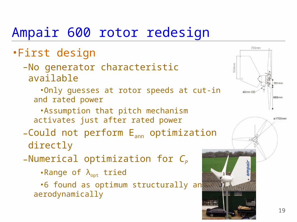
Ampair 600 rotor redesign
•First design–No generator characteristic available
•Only guesses at rotor speeds at cut-in and rated power
•Assumption that pitch mechanism activates just after rated power
–Could not perform Eann optimization directly
–Numerical optimization for CP
•Range of λopt tried
•6 found as optimum structurally and aerodynamically
19

Field tests were carried out on new rotor yielding a few insights
–Clearly require good generator spec.•Pitching mechanism performance also related
–Should be considering dynamic operation
20

Ampair 300 rotor redesign
•Well characterized generator–Passive PE
•Full Eann optimizer not yet available–Could now redo and impose torque matching constraint
–Numerical CP optimization•Range of λopt tried
–Post-process•Implicit torque matching
routines•Identify rotor with highest
energy yield
21
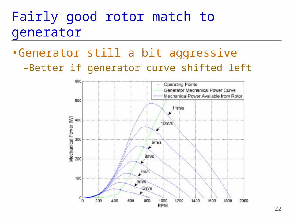
Fairly good rotor match to generator
•Generator still a bit aggressive–Better if generator curve shifted left
22

Imposition of cogging constraint changes rotor somewhat
•Effects–Larger chords–Startup now at 3m/s, vs. 5m/s for unconstrained design
–Generator more aggressive relative to rotor
23

A unique test apparatus was available…
•Equipment–Modified VW golf–12V load–Anemometer, tachometer, etc.
–Quiet UK country lane
–Windless day–Repeated/averaged runs
24
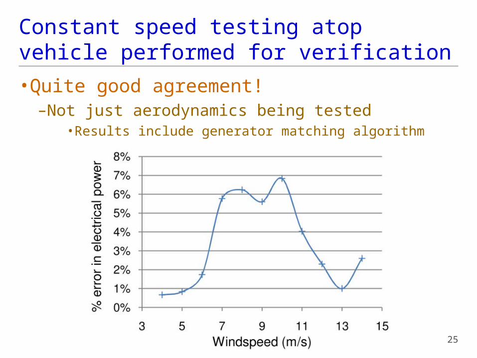
Constant speed testing atop vehicle performed for verification
•Quite good agreement!–Not just aerodynamics being tested
•Results include generator matching algorithm
25

6000 W clean sheet design
•Full Eann optimizer available
•Active PE–Variable speed
•Optimal power capture•VSS control above rated
–Generator characteristic contrived for these results•Data from dynamometer is being gathered•Expect efficiency degradation with partial power– Assume 70%-95% performance
26

0
100
200
300
020040060080010001200-0.5
0
0.5
1
1.5
2
2.5
3
x 104
Nrot gen
gen
Pow
erel
ec
Generator characteristic defined from “experimental” data points
27

Begin with simple analytic CP optimum and fit blade profiles with chord constraint
•Test range of λopt
–Implicit optimal operation algorithm
–Optimum around λ = 5-6–Performance hit with simple fitting procedure
28

Perform full Eann optimization with increasing cogging torque constraint
•Blade profiles
29
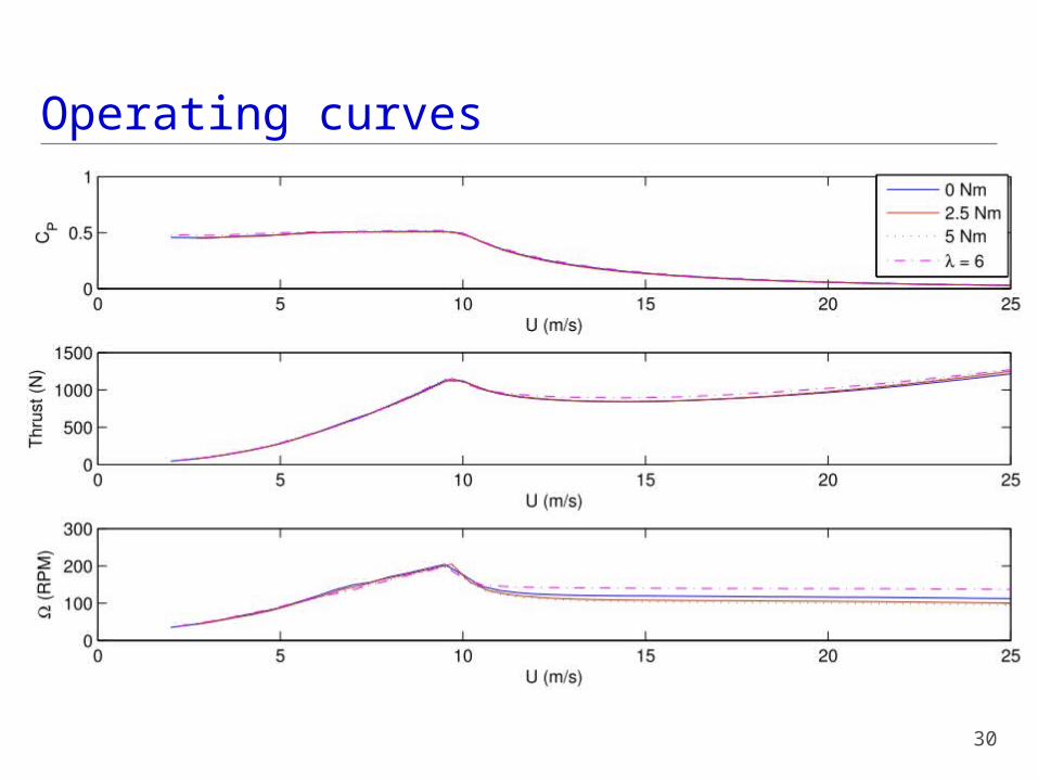
Operating curves
30
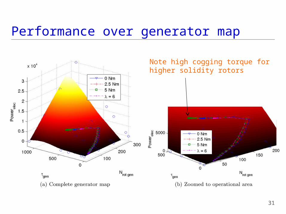
Performance over generator map
31
Note high cogging torque forhigher solidity rotors
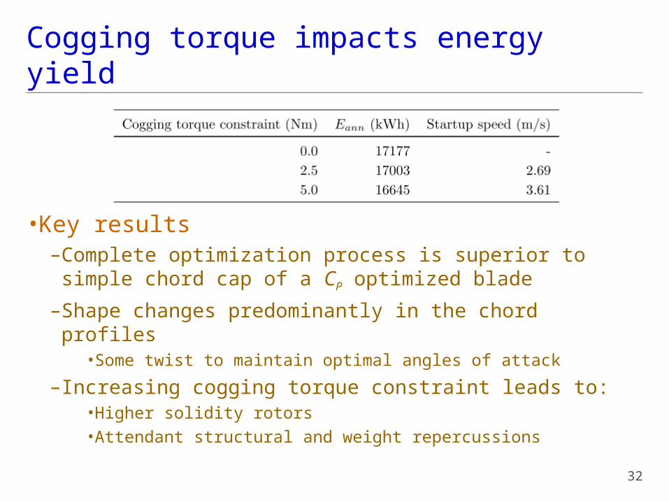
Cogging torque impacts energy yield
•Key results–Complete optimization process is superior to simple chord cap of a CP optimized blade
–Shape changes predominantly in the chord profiles•Some twist to maintain optimal angles of attack
–Increasing cogging torque constraint leads to:•Higher solidity rotors•Attendant structural and weight repercussions
32

Acoustic concerns over downwind rotor led to study of coning angle/offset
•Design point–Rated conditions (11m/s)
33

A compromise of 7° was reached between acoustics and stress
•Centrifugal moments build past 7°
34

Future directions
•More integration in MDO loop–Concurrent structures optimization–Generator/PE design
•Add DVs and constraints–Optimal blade lengths?–Tower thrust tradeoffs
•Include dynamic behavior–Stochastic winds–Effect on power curve–Fatigue loads?
35

Thanks are in order…
36
UVic Engineering Design Office