dps series - airtac · 2.software:set "cp-m" on master device. set "cp-s" on...
TRANSCRIPT
28.6
20
16
N
Made in Taiwan
12
A B C
D
EF
G
30
30
20
7
345 12
12 24V~
12 24V~
2-M3
MPa kPa kgf/cm bar
psi cmHgmmHg
IP64
2ms、20ms、50ms、100ms、250ms、500ms、1000ms、2500ms、5000ms
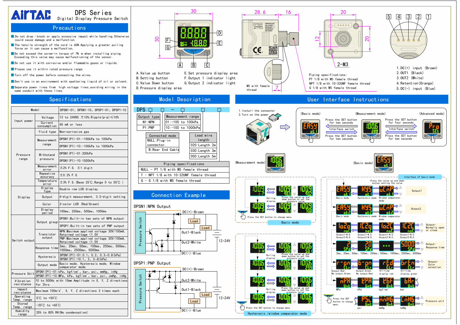
DPS Series
Precautions
Digital Display Pressure Switch
A.Value up buttonB.Setting button
C.Value Down buttonD.Pressure display area
E.Set pressure display areaF.Output 1 indicator light
G.Output 2 indicator light
Specifications Model Description User Interface Instructions
Connection Example
2.Turn on the power 1.Install the connector
(Measurement mode) (Basic mode)
(Measurement mode)(Basic mode) (Advanced mode)
Interface switch
Press the SET buttonfor two seconds
Press the SET buttonfor two seconds
Interface switch
Press the SET buttonfor four seconds
Press the SET buttonfor two seconds
Press the SET button to change menu
Press the value up anddown button to set the
pressure value
Press the value up anddown button to set the
pressure value
Press the value up anddown button to set the
pressure value
Rollingdisplay
Rollingdisplay
Rollingdisplay
Basic mode
Hysteresis /window comparator mode
Basic mode Hysteresis mode
Basic mode Hysteresis mode
Output1-N.O.Output2-N.O.
Output1-N.C.Output2-N.O.
Output1-N.O.Output2-N.C.
Output1-N.C.Output2-N.C.
Output:Red No output:Red
Press the SETbutton to changemenu
No output:GreenOutput:Green All-time
display redAll-timedisplay green
Press the value up and downbutton setting the value
Load
Do not use it with corrosive and/or flammable gases or liquids.
Don't use in an environment with spattering liquid of oil or solvent.
Do not drop、knock or apply excessive impact while handling.Otherwisecould cause damage and a malfunction.
The tensile strength of the cord is 60N.Applying a greater pullingforce on it can cause a malfunction.
Do not exceed the screw-in torque of 7N m when installing piping.Exceeding this value may cause malfunctioning of the sensor.
Please use it within rated pressure range.
Turn off the power before connecting the wires.
Separate power lines from high voltage lines,avoiding wiring in thesame conduit with these lines.
M5 with femalethread
Piping specifications:PT 1/8 with M5 female thread NPT 1/8 with 10-32UNF female threadG 1/8 with M5 female thread
1.DC(+) input (Brown)2.OUT1 (Black)
3.OUT2 (White)
4.Retention(Orange)
5.DC(-) input (Blue)
Maximum 100m/s , X, Y, Z directions 3 times each
0℃ to +50℃
-20℃ to +65℃
35% to 80% RH(No condensation)
Input power
Display
Switch output
Voltage
fluid type
Output
Color
Output group
Response time
12 to 24VDC ±10%,Ripple(p-p)≤10%
45 mA or less
Non-corrosive gas
DPSN1(P1)-01:-100kPa to 100kPa
DPSN1(P1)-10:-100kPa to 1000kPa
DPSN1(P1)-01:200kPa
DPSN1(P1)-10:1500kPa
±2% F.S. ±1 digit
±0.2% F.S.
100ms、250ms、500ms、1000ms
2-color LCD (Red/Green)
DPSN1:Built-in two sets of NPN output
DPSP1:Built-in two sets of PNP output
2ms、20ms、50ms、100ms、250ms、500ms、1000ms、2500ms、5000ms
±3% F.S.(Base 25℃,Range 0 to 50℃ )
Model DPSN1-01、DPSN1-10、DPSP1-01、DPSP1-10
Hysteresis
Output mode
Pressure Unit
Impactresistance
NPN:Maximum applied voltage 30V/100mA,Retained voltage <1.5V
OperatingTemp. range
Currentconsumption
Measurementrange
Pressurerange
Withstandpressure
Measurementerror
Repeativeaccuracy
Temperatureerror
DisplayType
Displayperiod
Transistoroutput
Double row LCD display
PNP:Maximum applied voltage 30V/100mA,Retained voltage <1.5V
Vibrationresistance
StoredTemp. rangeHumidityrange
Basic mode, Hysteresis mode, Windowcomparator mode
10 to 500Hz with 10mm Amplitude in X, Y, Z directionsfor 2hrs
2
4-digit measurement, 3.5-digit setting
DPSP1:PNP Output
DPSN1:NPN Output
Pressure Swi
tch
Pres
sure
Swi
tch
DC(+)-Brown
Out1-Black
Out2-White
DC(-)-Blue
Load
DC(+)-Brown
Out1-Black
Out2-White
DC(-)-Blue
Load
Load
Interface of basic mode
Pressure unit
Output1
Output-
Output-Response time
Output2
Normally openor close
Output-Colorselection
Output type
N1:NPN
P1:PNP
Piping specifications
NULL - PT 1/8 with M5 female thread
T - NPT 1/8 with 10-32UNF female thread
G - G 1/8 with M5 female thread
DPS -
020:Length 2m
030:Length 3m
Lead wirelength
Measurement range
01:-100 to 100kPa
10:-100 to 1000kPa
B:Rear End Cable
Connected modeNULL:Plug-inconnector.
Press the SET button to change menu
Window comparatormode
Window comparatormode
050:Length 5m
DPSN1(P1)-01:kPa、kgf/cm 、bar、psi、mmHg、inHgDPSN1(P1)-10:MPa、kPa、kgf/cm 、bar、psi、cmHg、inHg
DPSN1(P1)-01:0.1、0.2、0.3…0.8(kPa)DPSN1(P1)-10:1、2、3…8(kPa)
2
2
2
0
0
0
(Advanced mode)
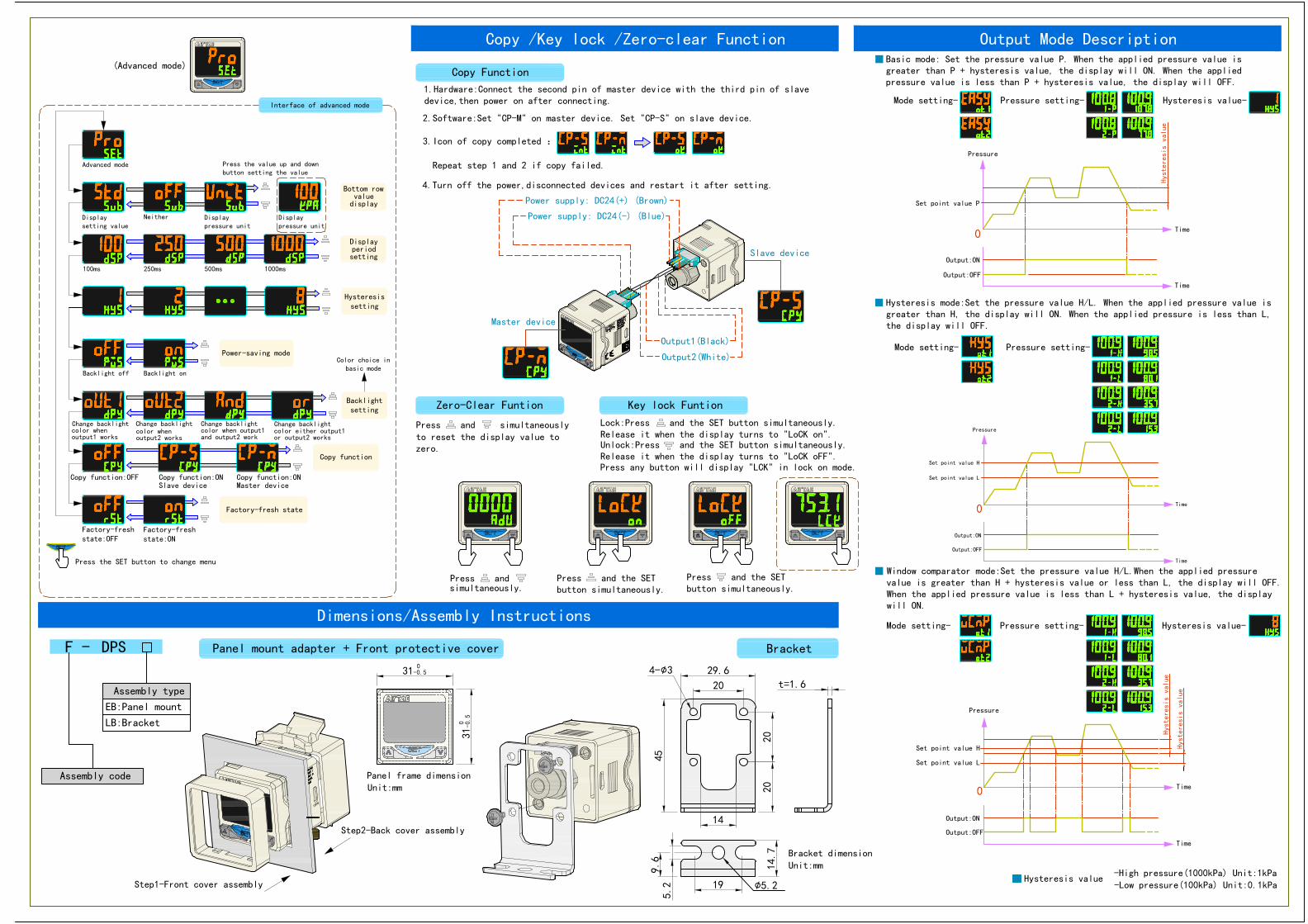
Dimensions/Assembly Instructions
Press the SET button to change menu
Advanced mode
Neither
100ms 250ms 500ms 1000ms
Backlight off Backlight on
Change backlight
Copy function:OFF
Change backlight Change backlight Change backlight
Copy function:ON Copy function:ONSlave device Master device
Displaypressure unit
Displaysetting value
Displaypressure unit
Press the value up and downbutton setting the value
Factory-freshstate:OFF
Factory-freshstate:ON
color whenoutput1 works
color whenoutput2 works
color when output1and output2 work
color either output1or output2 works
Power-saving mode
Copy function
Factory-fresh state
Hysteresissetting
Bottom rowvalue
display
Displayperiodsetting
Color choice inbasic mode
Backlightsetting
Copy Function
2.Software:Set "CP-M" on master device. Set "CP-S" on slave device.
3.Icon of copy completed :
4.Turn off the power,disconnected devices and restart it after setting.
1.Hardware:Connect the second pin of master device with the third pin of slavedevice,then power on after connecting.
Repeat step 1 and 2 if copy failed.
Power supply: DC24(+) (Brown)
Power supply: DC24(-) (Blue)
Output1(Black)
Output2(White)
Master device
Slave device
Zero-Clear Funtion Key lock Funtion
Press and simultaneously
Press any button will display "LCK" in lock on mode.
to reset the display value tozero.
Press and
Lock:Press and the SET button simultaneously.Release it when the display turns to "LoCK on".Unlock:Press and the SET button simultaneously.Release it when the display turns to "LoCK oFF".
Press and the SETbutton simultaneously.
Press and the SETbutton simultaneously.simultaneously.
BracketPanel mount adapter + Front protective coverDPS
Assembly type
EB:Panel mount
LB:Bracket
F -
Assembly code
29.645
2020
14
20
9.6
19
14.7
t=1.631
0-0.5
31 0 -0.5
4-∅3
∅5.2
5.2Step1-Front cover assembly
Step2-Back cover assembly
Panel frame dimensionUnit:mm
Bracket dimensionUnit:mm
-High pressure(1000kPa) Unit:1kPa -Low pressure(100kPa) Unit:0.1kPa
Hysteresis value
Pressure
Time
Set point value L
Time
Output:OFF
Output:ON
Set point value H
Mode setting- Pressure setting- Hysteresis value-
Window comparator mode:Set the pressure value H/L.When the applied pressurevalue is greater than H + hysteresis value or less than L, the display will OFF.When the applied pressure value is less than L + hysteresis value, the displaywill ON.
Hysteresis value
Hysteresis value
Pressure
Time
Set point value L
Time
Output:OFF
Output:ON
Set point value H
Mode setting- Pressure setting-
Hysteresis mode:Set the pressure value H/L. When the applied pressure value isgreater than H, the display will ON. When the applied pressure is less than L,the display will OFF.
Time
Set point value P
Time
Output:OFF
Output:ON
Pressure
Copy /Key lock /Zero-clear Function Output Mode Description
Mode setting-
Basic mode: Set the pressure value P. When the applied pressure value isgreater than P + hysteresis value, the display will ON. When the appliedpressure value is less than P + hysteresis value, the display will OFF.
Pressure setting- Hysteresis value-
Hysteresis value
Interface of advanced mode