dpm 2340 digital platemaster - rs prepress services · dpm 2340 digital platemaster with software...
TRANSCRIPT
DPM 2340Digital PlateMasterwith software 5.1 and above Operator’s Manual
ABDick - A Presstek Company55 Executive Dr.Hudson, NH 03051-4903
ii
• • • •••
©2005 ABDick - A Presstek Company
All rights reserved. No part of this publication may be duplicated, reproduced, or transmitted in any form or by any means, electronic or mechanical, including photocopy, recording or any information storage and retrieval system, without prior written consent of ABDick - A Presstek Company.
ABDick - A Presstek Company makes no representations or warranties with respect to the contents hereof and specifically disclaims any implied warranties of merchantability or fitness for any particular purpose. Further, ABDick - A Presstek Company reserves the right to revise this publication and to make changes from time to time in the contents hereof without obligation of ABDick - A Presstek Company to notify any person or organization of such revisions or changes.
ABDick - A Presstek Company disclaims any responsibility or liability for personal injury, death or property damage caused by or arising out of (i) the failure of operators to observe all operating and safety instructions and warnings contained herein or (ii) the improper use, abuse, neglect or unauthorized repair of the equipment described herein, and the purchaser and any subsequent owner or lessee of such equipment shall defend, indemnify and hold ABDick - A Presstek Company harmless from and against all liability caused or arising out of such nonobservance, improper use, abuse, neglect or unauthorized repair.
Mega and Mega Plus are trademarks of ABDick - A Presstek Company.
Warning: This is a Class A Product. In a domestic environment this product may cause radio interference, in which case the user may be required to take adequate measures. If this equipment does cause harmful interference to radio or television reception, which can be determined by turning the equipment off and on, the user is encouraged to try to correct the interference by one or more of the following measures:
— Reorient or relocate the receiving antenna.— Increase the separation between the equipment and receiver.— Connect the equipment into an outlet on a circuit different from that to which the receiver is connected.— Consult the dealer or an experienced radio/TV technician for help.
10 9 8 7 6 5 4 3 2Oct
WARNING: This Class A digital apparatus meets all requirements of the Canadian Interference-Causing Equipment Regulations.
Cet appareil numerique de la casse A respectetoutes les exigences du Reglement sur le materiel brouilleur du Canada.
WARNING: This is a Class A product per EN55022:1998. In a domestic environment this product may cause radio interference in which case the user may be required to take adequate measures.
iii • • • •••
• • • • • • Table of Contents
Introduction
Welcome . . . . . . . . . . . . . . . . . . . . . . . . . . . . . . . . . . . . . . . 1-1About this Manual . . . . . . . . . . . . . . . . . . . . . . . . . . . . . . . . 1-1Installing the DPM . . . . . . . . . . . . . . . . . . . . . . . . . . . . . . . . 1-3Safety . . . . . . . . . . . . . . . . . . . . . . . . . . . . . . . . . . . . . . . . . . 1-4Specifications . . . . . . . . . . . . . . . . . . . . . . . . . . . . . . . . . . . . 1-6
Getting Started
Locating the Major Areas . . . . . . . . . . . . . . . . . . . . . . . . . . 2-1Describing the Functional Operation . . . . . . . . . . . . . . . . . . 2-2Describing the Status Panel and Function Switch . . . . . . . . 2-4Describing the RIP Workstation . . . . . . . . . . . . . . . . . . . . . 2-6Describing the DPM Status Bar . . . . . . . . . . . . . . . . . . . . . . 2-8Setting Preferences . . . . . . . . . . . . . . . . . . . . . . . . . . . . . . 2-11Working with the Media Database . . . . . . . . . . . . . . . . . . 2-13Displaying Media Usage . . . . . . . . . . . . . . . . . . . . . . . . . . 2-15Supplies . . . . . . . . . . . . . . . . . . . . . . . . . . . . . . . . . . . . . . . 2-16Turning on the DPM . . . . . . . . . . . . . . . . . . . . . . . . . . . . . 2-17Shutting Down the DPM . . . . . . . . . . . . . . . . . . . . . . . . . . 2-18
Operating Basics
About Cassettes . . . . . . . . . . . . . . . . . . . . . . . . . . . . . . . . . . 3-1Replacing Media . . . . . . . . . . . . . . . . . . . . . . . . . . . . . . . . . 3-2Adjusting Media . . . . . . . . . . . . . . . . . . . . . . . . . . . . . . . . 3-12Explanation of the Exposure Sweep Test Pattern . . . . . . . 3-16Using the Take-up Cassette Accessory . . . . . . . . . . . . . . . 3-18Adjusting the Plate Catcher . . . . . . . . . . . . . . . . . . . . . . . . 3-20
Troubleshooting
Error Messages and Alerts . . . . . . . . . . . . . . . . . . . . . . . . . . 4-1Clearing Jams . . . . . . . . . . . . . . . . . . . . . . . . . . . . . . . . . . . . 4-7
Maintaining the DPM

iv
• • • •••
Servicing the DPM Quarterly . . . . . . . . . . . . . . . . . . . . . . . 5-1Changing the Air Filter . . . . . . . . . . . . . . . . . . . . . . . . . . . . 5-1Changing Chemicals . . . . . . . . . . . . . . . . . . . . . . . . . . . . . . 5-2
Appendix A
Supporting Applications . . . . . . . . . . . . . . . . . . . . . . . . . . A-1Locating Authorized ABDick International Subsidiaries A-1 Locating Authorized ABDick International Regional Offices
A-1Important Safety Warnings . . . . . . . . . . . . . . . . . . . . . . . . A-3
Index
1-1 • • • •••
Chapter 1
• • • • • • Introduction
WelcomeCongratulations on your purchase of the DPM (Digital PlateMaster). ABDick has combined leading-edge internal drum technology with reliable in-line processing to provide you with this state-of-the-art platemaker.
About this ManualThe DPM is an advanced platemaker using precision internal drum technology and an integrated processor. The platemaker interfaces with feature enhanced PrintersRIP® software.
This manual contains important information about installation, calibration, and daily use of the DPM, including working with the media cassettes, and processing systems.
Information about the PrintersRIP® and valuable tips about getting the most out of your RIP are found in the separate PrintersRIP® Operator’s Manual.
Each chapter of this manual has a specific focus. The information contained in these chapters are organized to provide ease of use and understanding leading you to effective use of the DPM.
Chapter 1 This chapter describes relevant information about safe operation of the DPM, specifications about the equipment and its installation, and also how to use this manual effectively.
Chapter 2 ‘Getting Started’ helps you to become familiar with the DPM. It also identifies essentials for getting up and running quickly, and how to sustain quality output from the equipment.
Chapter 3 ‘Operating Basics’ includes procedures used in the day-to-day operation of the platemaker.
Chapter 4 ‘Troubleshooting’ helps you resolve those infrequent occurrences when the DPM does not function as expected.
Chapter 5 ‘Maintaining the DPM’ provides procedures for keeping your platemaker operating at its best.
Chapter 6 ‘Appendix’ provides you with specific safety information, and a list of authorized ABDick International subsidiaries.

1-2
• • • •••
AssumptionsRead the DPM Operator’s Manual and the PrintersRIP® Operators Manual before starting to work with the platemaker.
This manual assumes you have some familiarity with digital platemaking as well as a basic knowledge of Microsoft Windows NT.
ConventionsCertain notational conventions have been applied to this manual to aid in understanding the information presented.
The following fonts and special symbols are used throughout this manual.
1 Paragraphs which are numbered contain instructions which you should follow.
Text written in the sans-serif bold face represents a menu title, menu item or control item in a dialogue box.
Text written in this bold typewriter face represents literal information which should be typed exactly as it appears in the manual.
Text written in italic and appearing within a sentence, is important related reference information.
Text written in bold italic and appearing within a sentence, represents a specific button on the DPM or on a menu window or dialogue box.
Text located in the left margin and preceded by an arrow, is important information about the topic presented at that point. It should be read carefully.
In addition, other graphics depicting buttons found within screens on the RIP Workstation will be displayed whenever appropriate.
Introduction 1-3
• • • •••
Intro
du
ctio
n
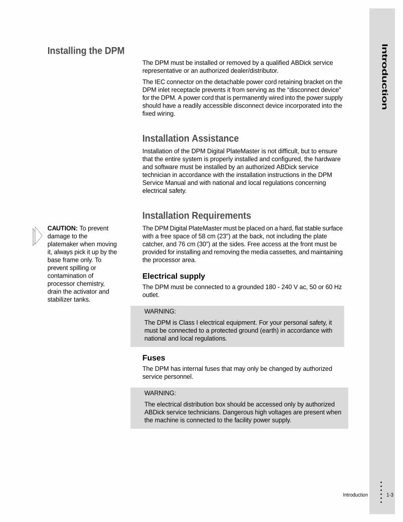
Installing the DPMThe DPM must be installed or removed by a qualified ABDick service representative or an authorized dealer/distributor.
The IEC connector on the detachable power cord retaining bracket on the DPM inlet receptacle prevents it from serving as the “disconnect device” for the DPM. A power cord that is permanently wired into the power supply should have a readily accessible disconnect device incorporated into the fixed wiring.
Installation AssistanceInstallation of the DPM Digital PlateMaster is not difficult, but to ensure that the entire system is properly installed and configured, the hardware and software must be installed by an authorized ABDick service technician in accordance with the installation instructions in the DPM Service Manual and with national and local regulations concerning electrical safety.
Installation RequirementsCAUTION: To prevent damage to the platemaker when moving it, always pick it up by the base frame only. To prevent spilling or contamination of processor chemistry, drain the activator and stabilizer tanks.
The DPM Digital PlateMaster must be placed on a hard, flat stable surface with a free space of 58 cm (23”) at the back, not including the plate catcher, and 76 cm (30”) at the sides. Free access at the front must be provided for installing and removing the media cassettes, and maintaining the processor area.
Electrical supplyThe DPM must be connected to a grounded 180 - 240 V ac, 50 or 60 Hz outlet.
FusesThe DPM has internal fuses that may only be changed by authorized service personnel.
WARNING:
The DPM is Class I electrical equipment. For your personal safety, it must be connected to a protected ground (earth) in accordance with national and local regulations.
WARNING:
The electrical distribution box should be accessed only by authorized ABDick service technicians. Dangerous high voltages are present when the machine is connected to the facility power supply.

1-4
• • • •••
SafetyProtect yourself, others, and your equipment by observing all safety warnings contained in this guide. Before attempting to operate the DPM, be certain that each operator has read this guide and is thoroughly familiar with the operating instructions and safety warnings. You will find a summary of safety data at the end of this guide.
Safety DevicesThe following illustrations identify and describe the function of the safety devices used on the DPM. Do not operate the PlateMaker without all covers, interlocks, and safety devices in their original, factory installed positions.
Safety Device Locations
WARNING:
This equipment is Class I rated electrical equipment and must be connected to a properly grounded, three (3) wire power supply in accordance with national and local regulations. Failure to do so creates a potential danger of electrical shock.
The circuit to which the equipment is connected must be current protected by a device with suitable interruption capability as required by national or local standards (whichever is the most stringent).
The power cord used to connect the equipment to the facility power supply must comply with national and local standards and must have a minimum rated current capacity of 20 Amp. (N.A.)/16 Amp. (Europe).
PROCESSOR ACCESS DOOR INTERLOCK SWITCHES
Two interlock switches are activated by the doors. The processor drive motor and heater are disabled when either door is open.
IMAGING UNIT ACCESS and LASER INTERLOCK SWITCHES
The four switches disable the laser unit when the light shield or a cover is removed.
NOTE: A LASER INTERLOCK SWITCH is located under this cover.
ON/OFF Switch/Circuit Breaker (15 A) is located on the back of the DPM.
Introduction 1-5
• • • •••
Intro
du
ctio
n
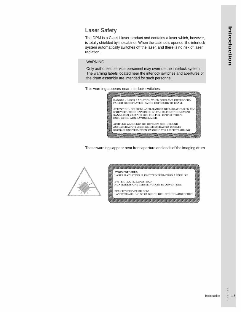
Laser SafetyThe DPM is a Class I laser product and contains a laser which, however, is totally shielded by the cabinet. When the cabinet is opened, the interlock system automatically switches off the laser, and there is no risk of laser radiation.
This warning appears near interlock switches.
These warnings appear near front aperture and ends of the imaging drum.
WARNING
Only authorized service personnel may override the interlock system. The warning labels located near the interlock switches and apertures of the drum assembly are intended for such personnel.

1-6
• • • •••
SpecificationsThis section includes important information regarding both functional and physical specifications for the DPM.
Functional SpecificationsImaging technology
Internal drum.
Light source
675-nm, 10mW visible red laser diode.
Maximum imaging area
35.5 x 49 cm (14” x 19.3”).
Resolution
900 to 3600 dpi
Speed of exposure
At 2400 dpi (28 full size plates per hour).
At 900 dpi (38 full size plates per hour).
Spot size
10 -30 microns, automatically matched to the chosen resolution.
Accuracy
(within an image)
+/- 25 microns.
Repeatability
(within an image)
+/- 5 microns.
Output media
RA process films.
Polyester and paper based plates.
Media loading
Daylight cassette with automated loading.
Media width
Plate: 22.9 cm to 34.0 cm / 9” to 13.4”.
Film: 22.9 cm to 35.6 cm / 9” to 14”.
Introduction 1-7
• • • •••
Intro
du
ctio
n
Media cassette capacity
61 m (200 feet).
Take-up cassette accessory capacity
10 m (33 feet).
Take-up cassette accessory dimensions (W x H x D)
45.2 x 13.3 x 12.7 cm (17.8” x 5.25” x 5.00”).
Physical specificationsDimensions (W x H x D) 1
37 x 114 x 71.1 cm (54” x 45” x 28” without Plate Catcher).
137 x 114 x 104 cm (54” x 45” x 41” with Plate Catcher).
Weight
306 kg / 675 lbs.
Power consumption (without accessories)
1400 W.
Rated voltage
180 / 200 / 208 / 220 / 230 / 240 VAC, 50/60 Hz.
Rated current
12 Amp.
Main circuit breaker
15 Amp / 250 V
In addition, the DPM has internal fuses that may only be changed by authorized service personnel.
Ambient temperature
18 to 27° C (65 - 80° F).
Relative humidity
30 - 70%
Noise level
Less than 70 dBA.
Data interface Differential Fast SCSI-2.

1-8
• • • •••
2-1 • • • •••
Chapter 2
• • • • • • Getting Started
This chapter provides useful information about your DPM and RIP Workstation. It will guide you to a basic understanding of the three main areas of the platemaker, initial default settings, and will highlight those things that are important in obtaining consistent quality results in a convenient manner.
Take time to read this chapter thoroughly before attempting any of the procedures found in the following chapters.
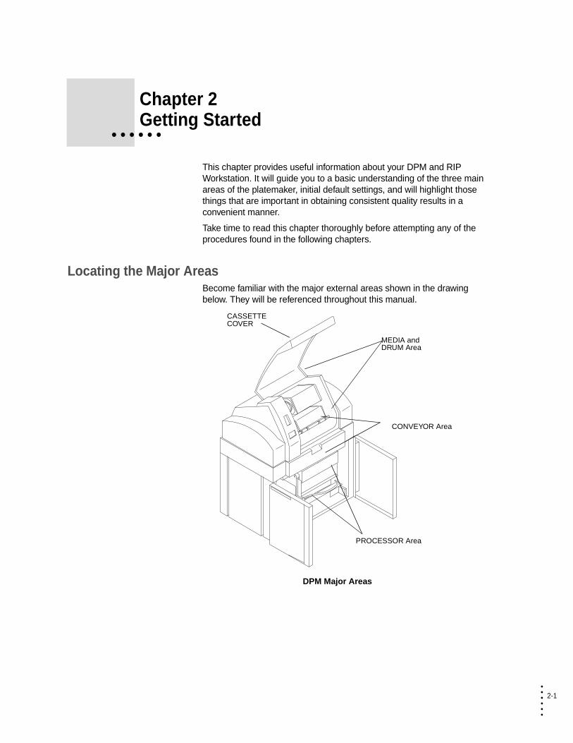
Locating the Major AreasBecome familiar with the major external areas shown in the drawing below. They will be referenced throughout this manual.
DPM Major Areas
CASSETTE COVER
PROCESSOR Area
MEDIA and DRUM Area
CONVEYOR Area

2-2
• • • •••
Describing the Functional OperationThe following is a brief description of the media path during the platemaking operation of the DPM.
Functional Diagram of the DPM
1 When the “Load” command is given, the feed rollers move the media to the input rollers which pull it from the media and load it into the drum.
During media loading, the carriage and optics unit is located to the middle of the drum. At each end of the carriage, a semicircu-lar guide hoop is mounted. These guides support the media dur-ing loading and prevent it from falling onto the optics unit. Sensors on the guides report an error to the PrintersRIP® if the media is not properly loaded.
2 The input and output rollers feed the media around the drum and through the output and knife module, holding the media securely in place.
The input and output sensors monitor the position of the media and report an error to the PrintersRIP® if the media is not loaded or positioned properly.
EXIT
Feed Rollers
Input Rollers
Output Rollers
ACTIVATOR TANKSTABILIZER
MEDIA
GUIDE BOX or TAKE-UP CASSETTE
PROCESSOR INPUT GUIDE
DRUM
Conveyor Rollers
Buffer
Knife
GUIDE HOOP

Getting Started 2-3
• • • •••
Gettin
g S
tarte
d
3 The optics unit moves to the right-hand end of the drum. The media is exposed from right to left.
The media is exposed by a laser which spins continuously around a central spindle as the carriage moves along the length of the drum. The carriage will only move as far as necessary to expose the job, depending on the format of the page and its orientation in the drum.
4 The input rollers and output rollers and buffer rollers then transfer the exposed media from the drum to the guide box.
At the same time, media for exposure of the next page enters the drum.
If the take-up cassette accessory is installed, the exposed media will leave the drum and enter the take-up cassette.
The knife cuts the media and the buffer rollers pass the media through the buffer module to the conveyor section and the pro-cessor.
If desired, the media in the drum can be removed using the UNLOAD command, and a different media can be installed.
If the take-up cassette accessory is installed, an EJECT com-mand can be issued. The media is cut, and the buffer rollers pass the media into the take-up cassette. The cassette can be removed and the media developed off-line.
2-4
• • • •••
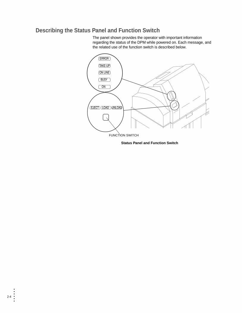
Describing the Status Panel and Function SwitchThe panel shown provides the operator with important information regarding the status of the DPM while powered on. Each message, and the related use of the function switch is described below.
Status Panel and Function Switch
ERROR
TAKE-UP
ON LINE
BUSY
ON
EJECT LOAD UNLOAD
FUNCTION SWITCH

Getting Started 2-5
• • • •••
Gettin
g S
tarte
d
Status PanelThe messages indicate the operational status of the DPM.
Media messages and the function switchThe media messages relate specifically to the status of the media in the drum. Only one of these messages is displayed at a time.
Pushing the Function Switch carries out the function displayed:
Message Function
ON illuminates whenever the power is switched on to the DPM.
BUSY illuminates whenever the DPM is carrying out an operation, i.e., during platemaking or media transport.
ON LINE illuminates whenever the power is switched on, unless in service mode, or an interlock is open.
When not illuminated, the DPM is off-line with respect to the Print-ersRIP®, and you will not be able to image media.
TAKE-UP illuminates after an EJECT command has been performed, to show that the media has been cut and the media has been forwarded to the Take-up Cassette.
The take-up cassette accessory, if installed, can be removed and the media developed in an off-line processor.
also illuminates when the platemaker detects that neither the Guide Box nor the Take-up Cassette are installed when the platemaker is ready to advance media from the Drum.
ERROR illuminates if an error occurs in the functioning of the DPM. See “Troubleshooting” on page 4-1.
Message Function
EJECT illuminates when imaged media is ready to be inserted into the Take-up Cassette. Pushing the function switch will cause the media to be cut by the knife and then transported forward until it is free of the buffer rollers.
LOAD illuminates when a different media has been placed in the DPM. Pushing the function switch transports the media into the drum for exposure.
LOAD flashes if the media is out of media.
UNLOAD illuminates when no imaged media is in the drum, and the platemaker is not busy. Pushing the function switch will cause the media to be removed from the drum.
The media can be removed/changed at this time.
NOTE: LOAD, EJECT and UNLOAD can also be performed from the Media Settings window at the RIP Workstation.
2-6
• • • •••
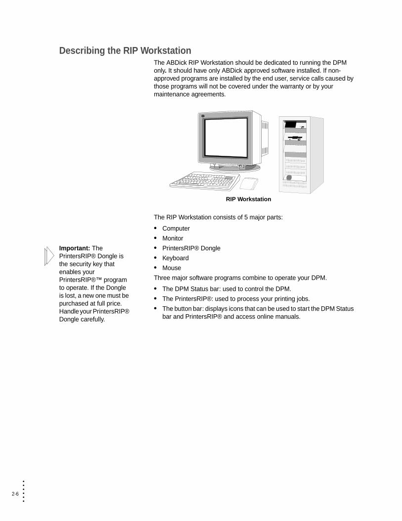
Describing the RIP WorkstationThe ABDick RIP Workstation should be dedicated to running the DPM only. It should have only ABDick approved software installed. If non-approved programs are installed by the end user, service calls caused by those programs will not be covered under the warranty or by your maintenance agreements.
RIP Workstation
The RIP Workstation consists of 5 major parts:
• Computer
• Monitor
Important: The PrintersRIP® Dongle is the security key that enables your PrintersRIP®™ program to operate. If the Dongle is lost, a new one must be purchased at full price. Handle your PrintersRIP® Dongle carefully.
• PrintersRIP® Dongle
• Keyboard
• Mouse
Three major software programs combine to operate your DPM.
• The DPM Status bar: used to control the DPM.
• The PrintersRIP®: used to process your printing jobs.
• The button bar: displays icons that can be used to start the DPM Status bar and PrintersRIP® and access online manuals.

Getting Started 2-7
• • • •••
Gettin
g S
tarte
d
The button bar displays icons for the PrintersRIP® and DPM Status window.
Button Bar
Starts the PrintersRIP® program and also makes the program window appear if it is minimized, or hidden behind another window. See your PrintersRIP® manual for more information on the RIP operations.
Starts the DPM Status bar. See “Describing the DPM Status Bar” on page 2-8 for more information on the status bar.
Opens a program window containing electronic versions of the PrintersRIP® Operators Manual, and the DPM Operators Manual.
2-8
• • • •••
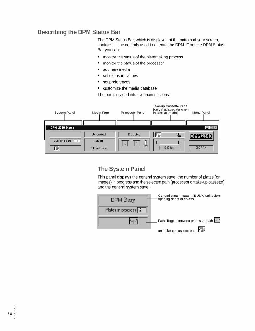
Describing the DPM Status BarThe DPM Status Bar, which is displayed at the bottom of your screen, contains all the controls used to operate the DPM. From the DPM Status Bar you can:
• monitor the status of the platemaking process
• monitor the status of the processor
• add new media
• set exposure values
• set preferences
• customize the media database
The bar is divided into five main sections:
The System PanelThis panel displays the general system state, the number of plates (or images) in progress and the selected path (processor or take-up cassette) and the general system state.
System Panel Media Panel Processor Panel
Take-up Cassette Panel (only displays data when in take-up mode) Menu Panel
General system state: If BUSY, wait before opening doors or covers.
Path: Toggle between processor path
and take-up cassette path.
Getting Started 2-9
• • • •••
Gettin
g S
tarte
d
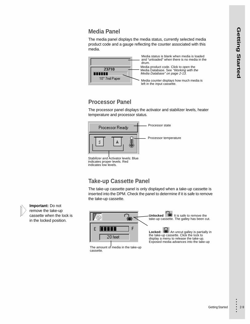
Media PanelThe media panel displays the media status, currently selected media product code and a gauge reflecting the counter associated with this media.
Processor PanelThe processor panel displays the activator and stabilizer levels, heater temperature and processor status.
Take-up Cassette PanelThe take-up cassette panel is only displayed when a take-up cassette is inserted into the DPM. Check the panel to determine if it is safe to remove the take-up cassette.
Important: Do not remove the take-up cassette when the lock is in the locked position.
Media status is blank when media is loaded and “unloaded” when there is no media in the drum.Media product code. Click to open the Media Database. See “Working with the Media Database” on page 2-13.
Media counter displays how much media is left in the input cassette.
Processor state
Processor temperature
Stabilizer and Activator levels: Blue indicates proper levels. Red indicates low levels.
Unlocked It is safe to remove the take-up cassette. The galley has been cut.
Locked: An uncut galley is partially in the take-up cassette. Click the lock to display a menu to release the take-up. Exposed media advances into the take-up
The amount of media in the take-up cassette.

2-10
• • • •••
Menu PanelClick DPM in the menu panel to display menus for customizing and managing the DPM.
For instructions on Setting Preferences, see “Setting Preferences” on page 2-11.
For instructions on Media Setup, see “Working with the Media Database” on page 2-13.
For instructions on Media Usage, see “Displaying Media Usage” on page 2-15.
From the service menu you can open a terminal window.
Getting Started 2-11
• • • •••
Gettin
g S
tarte
d
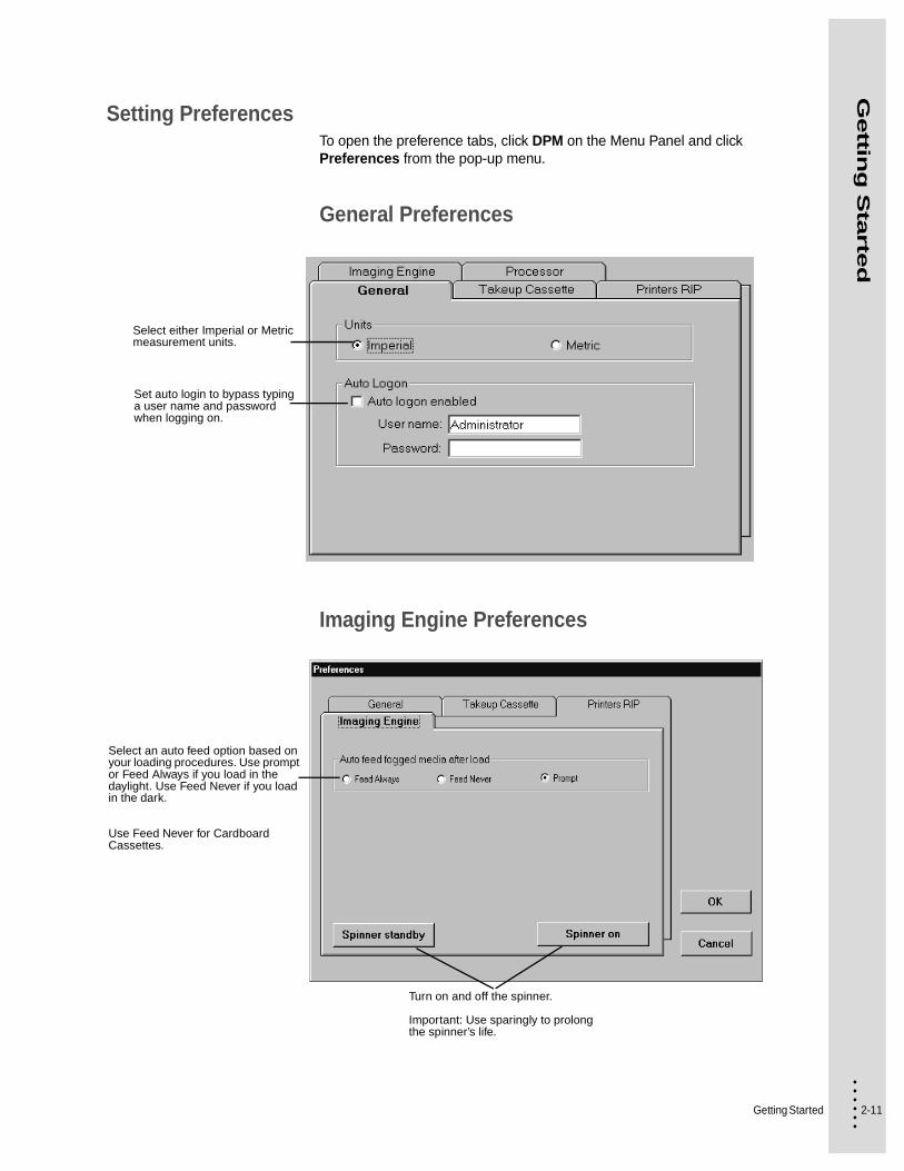
Setting PreferencesTo open the preference tabs, click DPM on the Menu Panel and click Preferences from the pop-up menu.
General Preferences
Imaging Engine Preferences
Select either Imperial or Metric measurement units.
Set auto login to bypass typing a user name and password when logging on.
Turn on and off the spinner.
Important: Use sparingly to prolong the spinner’s life.
Select an auto feed option based on your loading procedures. Use prompt or Feed Always if you load in the daylight. Use Feed Never if you load in the dark.
Use Feed Never for Cardboard Cassettes.

2-12
• • • •••
Printers RIP Preferences
Take-up Cassette Preferences
Zoom levels range from 1:64 (farthest away) to 1:8 (closest). The default is 1:64. A change to the Roam preference, takes effect the next time you restart the PrintersRip®
The maximum take-up capacity is 33 feet (10 m). The media is automatically cut when it reaches maximum capacity.
Set the minimum galley leader to match your offline processor.
Getting Started 2-13
• • • •••
Gettin
g S
tarte
d
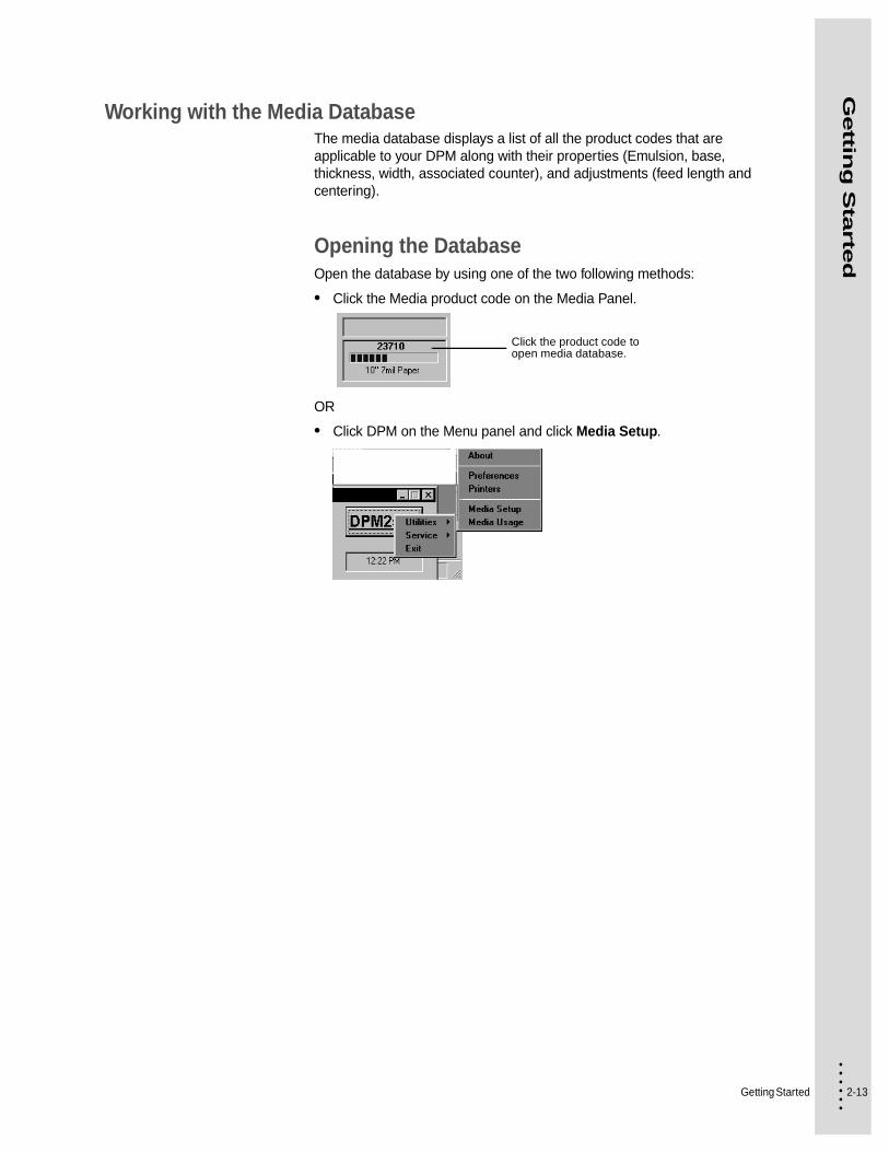
Working with the Media DatabaseThe media database displays a list of all the product codes that are applicable to your DPM along with their properties (Emulsion, base, thickness, width, associated counter), and adjustments (feed length and centering).
Opening the DatabaseOpen the database by using one of the two following methods:
• Click the Media product code on the Media Panel.
OR
• Click DPM on the Menu panel and click Media Setup.
Click the product code to open media database.

2-14
• • • •••
Using the Media Settings Window
Customizing the DatabaseYou can customize the database display to display only selected media or to sort the media.
Select which product codes you want displayed in this list by double-clicking in the Show column to toggle between Yes and No. Select the Show All box, in the bottom left of the window, to show all product codes. Unclick it to show only the ones selected for show (yes).
Sort the database according to your criteria by clicking the column headings.
See “To adjust exposure values:” on page 3-13.
Advances the media by a full-plate length.
Loads media into the drum in preparation for imaging.
In Take-up mode (negative film and take-up cassette loaded), this transports the imaged film into the take-up cassette.
Returns media from the drum.
Click a media to select it. See “To adjust
the image centering on the plate:” on page 3-15.
See “To adjust the plate length:” on page 3-14.
Getting Started 2-15
• • • •••
Gettin
g S
tarte
d
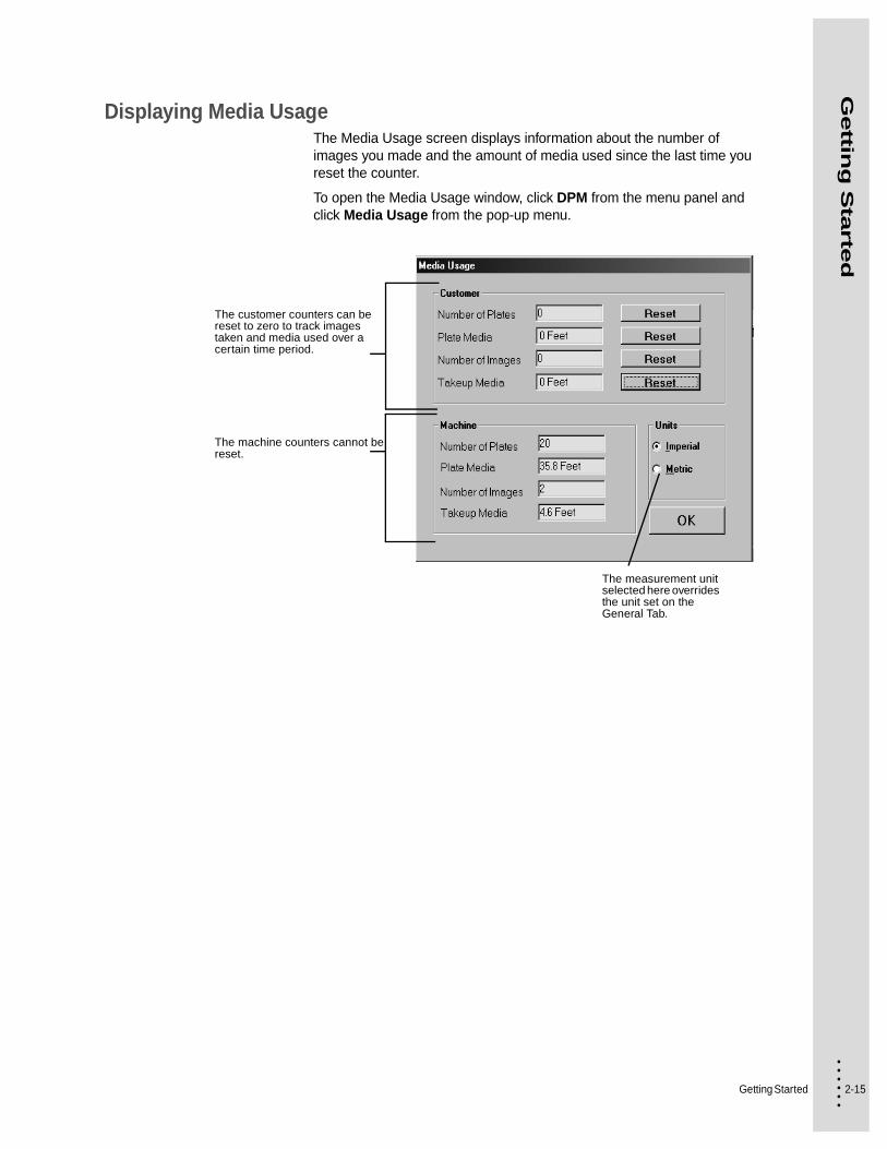
Displaying Media UsageThe Media Usage screen displays information about the number of images you made and the amount of media used since the last time you reset the counter.
To open the Media Usage window, click DPM from the menu panel and click Media Usage from the pop-up menu.
The customer counters can be reset to zero to track images taken and media used over a certain time period.
The machine counters cannot be reset.
The measurement unit selected here overrides the unit set on the General Tab.

2-16
• • • •••
Supplies
Tips About Supplies• Maintaining the proper level of chemicals in the processor tanks is very
important. Although the DPM will detect low chemical levels, best performance is obtained by checking the replenisher bottles daily and keeping them filled.
• Plate media is light sensitive. Always store it in its original containers (plastic bag and box), or in a input cassette.
• Store plate media away from sources of excessive heat, like radiators and direct sunlight.
• Avoid touching the printing surface of media.
• Use ABDick activator, stabilizer, etch, and fountain solution for best results.
WARNING
Use only ABDick brand media and chemicals for optimum results and equipment life. The use of other brands, that result in damage to the equipment, may void warranty protection and result in termination or non-renewal of any maintenance agreement. Contact ABDick for compatibility requirements between media and chemicals.
Getting Started 2-17
• • • •••
Gettin
g S
tarte
d
Turning on the DPMWhen you power on the DPM, the processor begins its warm-up cycle. When the software is completely loaded, the ON LINE message illuminates. Always wait for the ON LINE light to appear before you perform any operation, including shutting down the DPM.
Important: If you need to power on the DPM immediately after powering it off, wait at least 10 seconds to prevent damage to the electronic circuitry of the PlateMaker
Because the warm-up cycle heats the processor chemicals to their operating temperature, always be sure the tanks are filled with chemicals before you power on the DPM. If the tanks are empty at power up, the warm-up circuitry will not turn on. The liquid level must be kept within 6 mm (1/4”) of “Full” operating level for proper operation.
To power on the DPM:
1 Check that both processor tanks are filled with chemicals. If they are not, see “Filling the processor with chemicals” on page 5-5.
2 Fill the replenisher bottles with pre-mixed activator and stabilizer each day. Do not make plates if the replenisher bottles are empty or not in place.
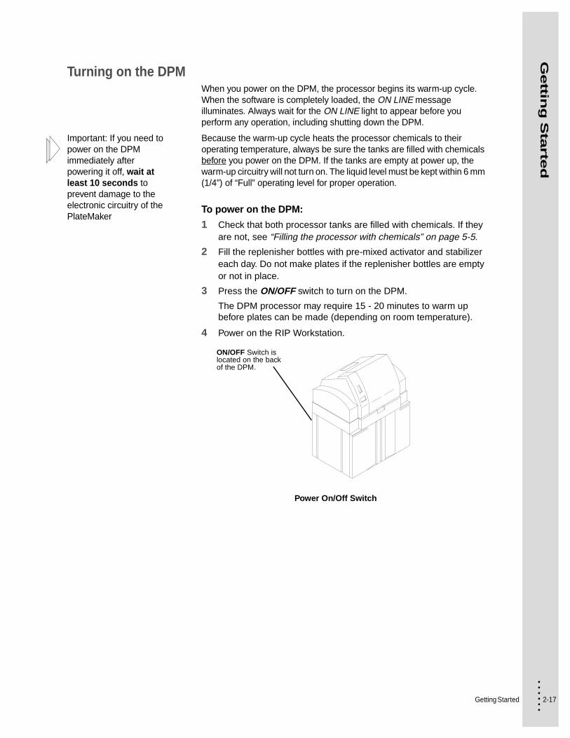
3 Press the ON/OFF switch to turn on the DPM.
The DPM processor may require 15 - 20 minutes to warm up before plates can be made (depending on room temperature).
4 Power on the RIP Workstation.
Power On/Off Switch
ON/OFF Switch is located on the back of the DPM.

2-18
• • • •••
Shutting Down the DPMThe DPM machine may be turned off and on without shutting off the RIP Workstation.
If the RIP Workstation has also been turned off, do not turn it on again until the DPM has been turned on and has completed the boot up cycle (Status Panel lights illuminated).
To power off the RIP Workstation
1 Close the software programs by one of the following methods.
• In File on the menu bar, select Close.
• Click the Close (“X”) Window Control Button in the upper right corner of the program title bar.
• Double-click the Control-menu Icon in the upper left corner of the program title bar.
Follow directions in any dialogue box that may appear.
2 On the Start menu, select Shut Down.
3 When the Shut Down Window appears, select Shut down and click on the OK button.
4 When the OK To Turn Your Computer Off appears, turn off the RIP Workstation.

3-1 • • • •••
Chapter 3
• • • • • • Operating Basics
This chapter covers the procedures used in the daily operation of the DPM. It includes information about working with media, cassettes, and relevant RIP Workstation activities.
About CassettesThe DPM uses ABDick brand media. Follow the steps in this chapter to ensure that the media is properly loaded.
The input cassette and Take-up Cassette are conveniently accessible from the front of the DPM. The input cassette is in the upper position and the guide box is located under the input cassette. If you have the Take-up Cassette Accessory (used when running negative film), it is located where the guide box is shown here. See “Using the Take-up Cassette Accessory” on page 3-18 in this chapter for specific procedures in the use of this accessory.
Cassette Locations
Media
Guide Box or Take-up Cassette
Cassette Cover

3-2
• • • •••
Replacing MediaTwo types of input cassettes can be used with the DPM—cardboard or reloadable.
Replacing an input cassette involves the following steps:
• Remove the old media
To remove a Cardboard Cassette: See page 2.
To remove a reloadable cassette: See page 8.
• Insert the new media
To load a cardboard cassette: See page 6.
To load a reloadable cassette See page 10.
• Set the media type. See page 12 and load it into the drum.
• Adjust the exposure (if necessary). See page 13.
• Adjust the plate length (if necessary). See page 14.
• Adjust the centering on the plate (if necessary). See page 15.
Working with Cardboard Cassettes
To remove a Cardboard Cassette:
1 If the BUSY message is illuminated, wait for it to go out.
BUSY message
ERROR
TAKE-UP
ON LINE
BUSY
ON
EJECT LOAD UNLOAD
Operating Basics 3-3
• • • •••
Op
era
ting
Basic
s
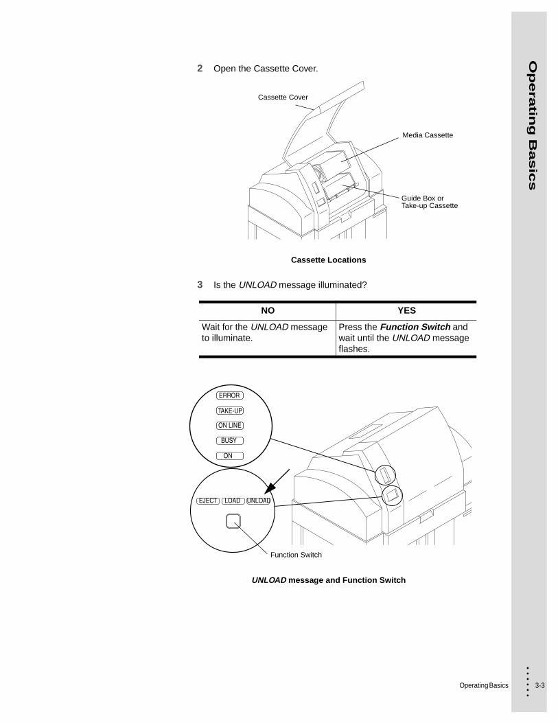
2 Open the Cassette Cover.
Cassette Locations
3 Is the UNLOAD message illuminated?
UNLOAD message and Function Switch
NO YES
Wait for the UNLOAD message to illuminate.
Press the Function Switch and wait until the UNLOAD message flashes.
Media Cassette
Guide Box or Take-up Cassette
Cassette Cover
ERROR
TAKE-UP
ON LINE
BUSY
ON
EJECT LOAD UNLOAD
Function Switch

3-4
• • • •••
4 Partially remove the cassette and adapter.
Push down on the two holding forks and slide the cassette toward you to the stop.
Removing the cassette
5 Wait for the BUSY message to go out. Remove the cassette from the two upper forks.
BUSY message
Cassetteand adapter
Cassette Cover
Fork
ERROR
TAKE-UP
ON LINE
BUSY
ON
EJECT LOAD UNLOAD
Operating Basics 3-5
• • • •••
Op
era
ting
Basic
s
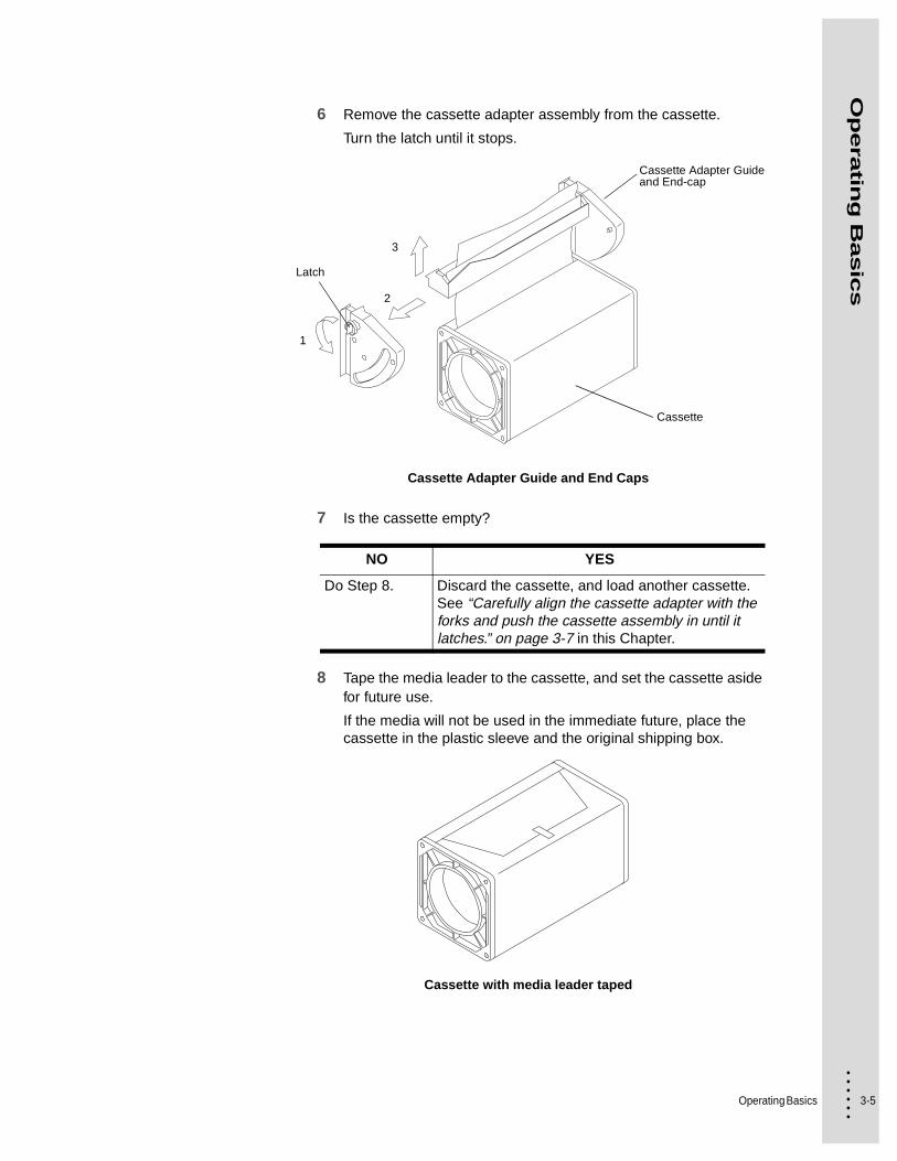
6 Remove the cassette adapter assembly from the cassette.
Turn the latch until it stops.
Cassette Adapter Guide and End Caps
7 Is the cassette empty?
8 Tape the media leader to the cassette, and set the cassette aside for future use.
If the media will not be used in the immediate future, place the cassette in the plastic sleeve and the original shipping box.
Cassette with media leader taped
NO YES
Do Step 8. Discard the cassette, and load another cassette. See “Carefully align the cassette adapter with the forks and push the cassette assembly in until it latches.” on page 3-7 in this Chapter.
Cassette
Cassette Adapter Guide and End-cap
1
2
3
Latch
3-6
• • • •••
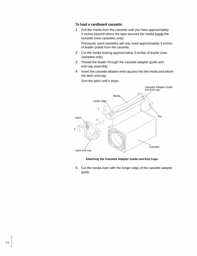
To load a cardboard cassette:
1 Pull the media from the cassette until you have approximately 5 inches beyond where the tape secured the media inside the cassette (new cassettes only).
Previously used cassettes will only need approximately 3 inches of leader pulled from the cassette.
2 Cut the media leaving approximately 3 inches of leader (new cassettes only).
3 Thread the leader through the cassette adapter guide and end-cap assembly.
4 Insert the cassette adapter end-cap pins into the media and attach the latch end-cap.
Turn the latch until it stops.
Attaching the Cassette Adapter Guide and End Caps
5 Cut the media even with the longer edge of the cassette adapter guide.
Cassette
Pin
Media
Latch end-cap
Cassette Adapter Guide and End-cap
Guide edge
1
2
3
Latch
Operating Basics 3-7
• • • •••
Op
era
ting
Basic
s
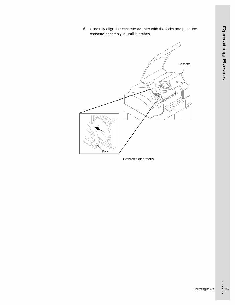
6 Carefully align the cassette adapter with the forks and push the cassette assembly in until it latches.
Cassette and forks
Fork
Cassette
3-8
• • • •••
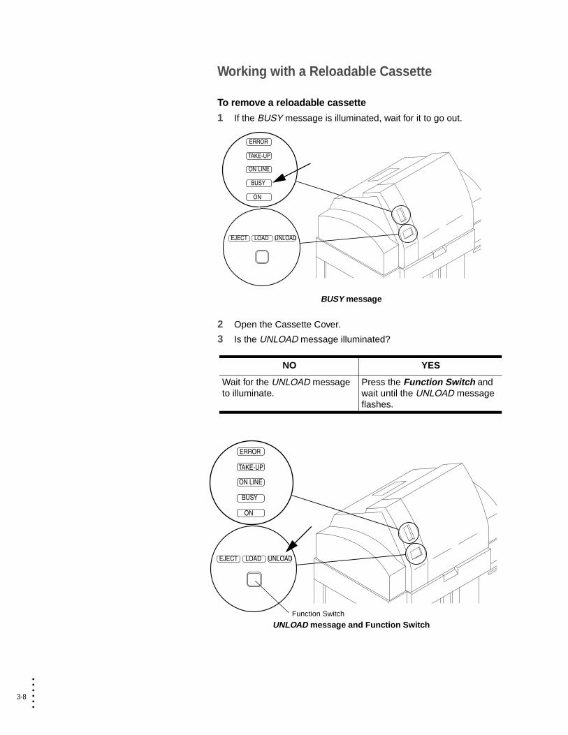
Working with a Reloadable Cassette
To remove a reloadable cassette
1 If the BUSY message is illuminated, wait for it to go out.
BUSY message
2 Open the Cassette Cover.
3 Is the UNLOAD message illuminated?
UNLOAD message and Function Switch
NO YES
Wait for the UNLOAD message to illuminate.
Press the Function Switch and wait until the UNLOAD message flashes.
ERROR
TAKE-UP
ON LINE
BUSY
ON
EJECT LOAD UNLOAD
ERROR
TAKE-UP
ON LINE
BUSY
ON
EJECT LOAD UNLOAD
Function Switch
Operating Basics 3-9
• • • •••
Op
era
ting
Basic
s
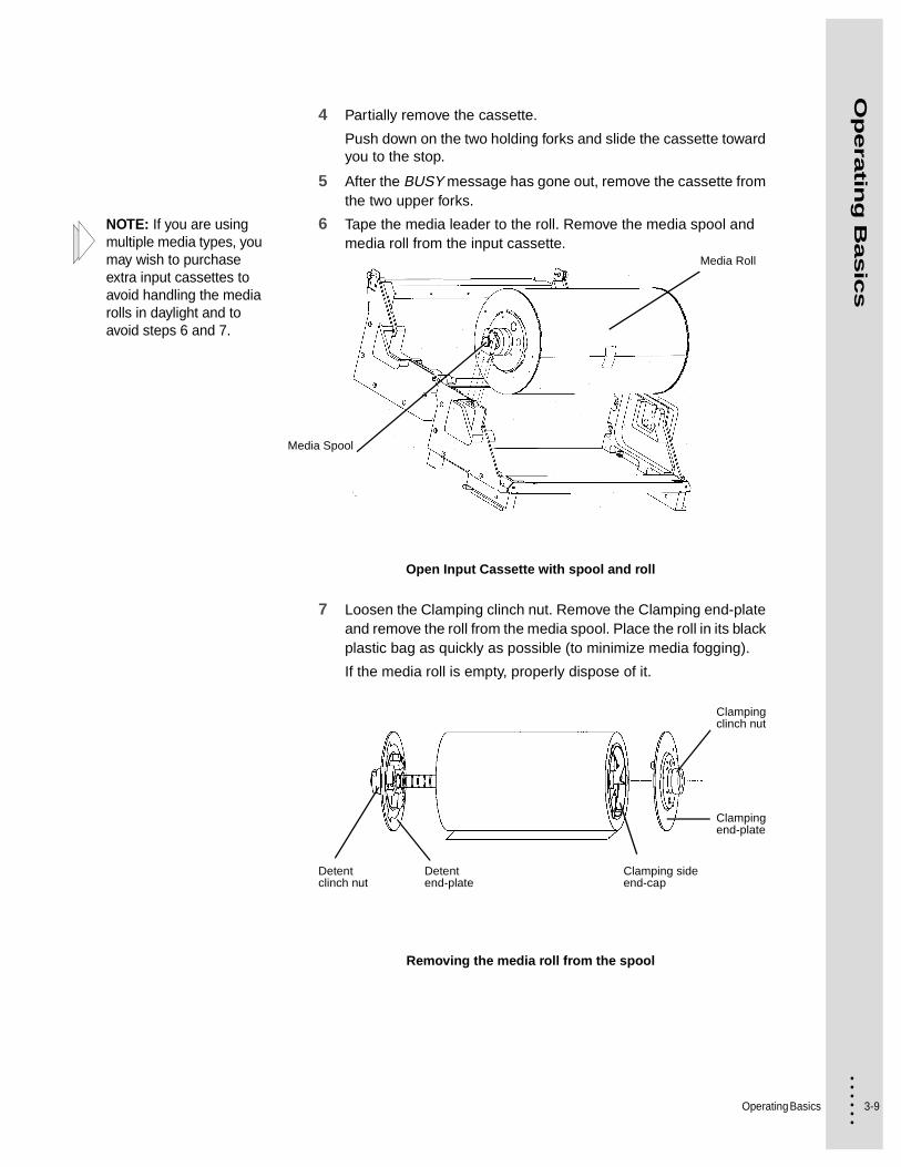
4 Partially remove the cassette.
Push down on the two holding forks and slide the cassette toward you to the stop.
5 After the BUSY message has gone out, remove the cassette from the two upper forks.
NOTE: If you are using multiple media types, you may wish to purchase extra input cassettes to avoid handling the media rolls in daylight and to avoid steps 6 and 7.
6 Tape the media leader to the roll. Remove the media spool and media roll from the input cassette.
Open Input Cassette with spool and roll
7 Loosen the Clamping clinch nut. Remove the Clamping end-plate and remove the roll from the media spool. Place the roll in its black plastic bag as quickly as possible (to minimize media fogging).
If the media roll is empty, properly dispose of it.
Removing the media roll from the spool
Media Spool
Media Roll
Clamping clinch nut
Clamping end-plate
Clamping side end-cap
Detent end-plate
Detent clinch nut

3-10
• • • •••
To load a reloadable cassette
1 Adjust the detent end-plate for the size media you wish to load.
2 Remove the media roll from its black plastic bag. Place the roll on a flat surface with the media leader coming off the bottom of the roll, and away from you. Remove the Clamping end-plate from the spool, if it is on.
3 Insert the media spool into the large center hole of the media roll Detent side end-cap. Feed the spool through the large center hole in the media spool Clamping side end-cap.
Insert media spool
Detent side end-cap
Media wrap direction
Clamping end-plate
Media spool
Detent end-plate

Operating Basics 3-11
• • • •••
Op
era
ting
Basic
s
4 Rotate the media spool assembly until the pins line up with their matching end-cap holes, and slide the spool toward the media roll left until it stops.
5 Place the Clamping end-plate onto the media spool assembly. Rotate the Clamping end-plate until its pins line up with the media roll end-cap holes. Slide the Clamping end-plate towards the media roll until it stops. Gently hand tighten the clinch nut on the Clamping end-plate.
Note: There should not be a gap between the end plates and media spool.
6 Place the open input cassette on a flat surface. The top of the cassette should face away from you.
7 Place the media spool into the bottom of the cassette.
8 Remove the tape from the media roll leader, and pull a few inches out of the cassette. Close and latch the lid.
Pulling media leader from cassette
9 Trim the front edge of the media across the lower guide.
10 Carefully align the cassette with the DPM forks and push until it latches.

3-12
• • • •••
Adjusting Media
To set the media type
Note: Every time you change the media type, you must tell the DPM software what type of media you installed.
1 Click the media panel of the DPM Status window screen.
The Media Settings window opens.
Media Database
2 Click the product code that you just inserted.
3 Click Load.
The media is loaded into the drum.

Operating Basics 3-13
• • • •••
Op
era
ting
Basic
s
Note: The DPM software calculates the job exposure based on the selected media types and the job resolution. You can, however, set the exposure more precisely for any given media product code/resolution combination. If you are using a product code for the first time you must adjust the exposure setting.
To adjust exposure values:
1 With the product code highlighted on the Media Settings screen, click Exposure.
The Exposure Settings window opens.
Note: If the resolution is not already in the list, you can add it by clicking Add Resolution.
2 Click the resolution that your are running for your jobs.
3 Click Fine sweep to output a plate with several strips of the exposure sweep test pattern, each exposed with a different exposure value at small increments. The base exposure is the value shown on the slider. See “Explanation of the Exposure Sweep Test Pattern” on page 3-16.
4 Examine the plate and find the strip where the circles disappear into the background. Note the exposure setting displayed on the left side of the strip.
5 Change the exposure slider to reflect the value in step 4. Click Set as Current.
6 Click Save.
7 Click OK.
3-14
• • • •••
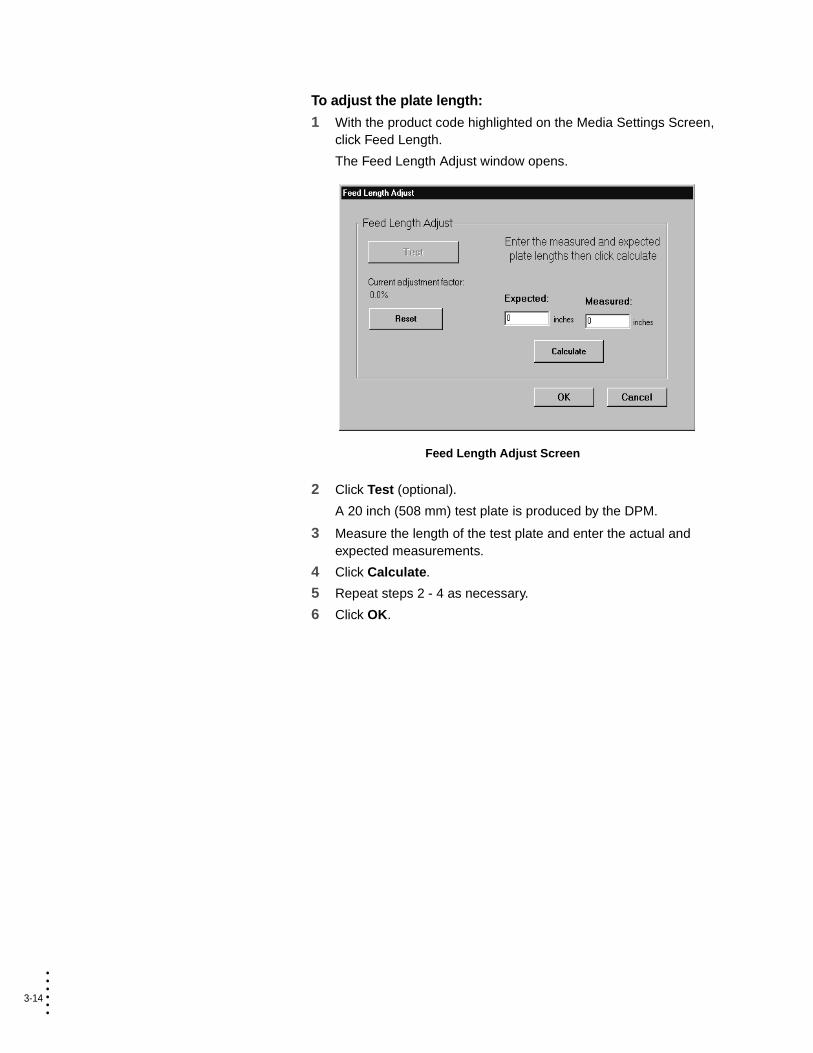
To adjust the plate length:
1 With the product code highlighted on the Media Settings Screen, click Feed Length.
The Feed Length Adjust window opens.
Feed Length Adjust Screen
2 Click Test (optional).
A 20 inch (508 mm) test plate is produced by the DPM.
3 Measure the length of the test plate and enter the actual and expected measurements.
4 Click Calculate.
5 Repeat steps 2 - 4 as necessary.
6 Click OK.

Operating Basics 3-15
• • • •••
Op
era
ting
Basic
s
To adjust the image centering on the plate:
1 With the product code highlighted on the Media Settings Screen, click Centering.
The Center Adjust window opens.
Center Adjust Screen
2 Click Test (optional).
A centering adjustment plate is produced by the DPM.
Centering Adjustment Plate
3 Measure the distance from both the right and left edges to the center line on the target.
4 Enter the measured distances.
5 Click Calculate.
6 Click OK.
LEFT
TOP
(Measure distance fromcenter to left edge
of material)
RIGHT
Offset =RIGHT - LEFT
2
* Offset may be positive or negative
(Measure distance fromcenter to right edge
of material)
3-16
• • • •••
Explanation of the Exposure Sweep Test Pattern
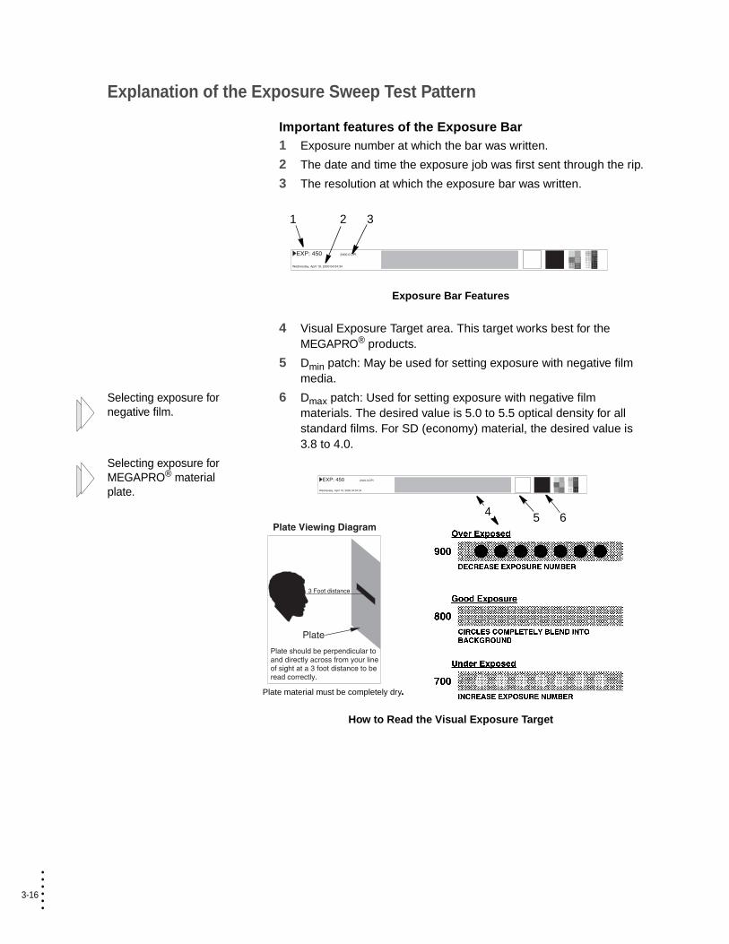
Important features of the Exposure Bar1 Exposure number at which the bar was written.
2 The date and time the exposure job was first sent through the rip.
3 The resolution at which the exposure bar was written.
Exposure Bar Features
4 Visual Exposure Target area. This target works best for the MEGAPRO® products.
5 Dmin patch: May be used for setting exposure with negative film media.
Selecting exposure for negative film.
6 Dmax patch: Used for setting exposure with negative film materials. The desired value is 5.0 to 5.5 optical density for all standard films. For SD (economy) material, the desired value is 3.8 to 4.0.
Selecting exposure for MEGAPRO® material plate.
How to Read the Visual Exposure Target
1 2 3
5 64
Plate material must be completely dry.
Operating Basics 3-17
• • • •••
Op
era
ting
Basic
s
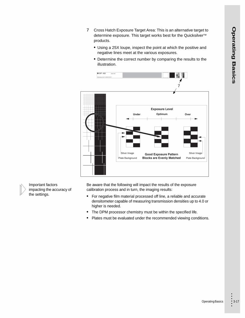
7 Cross Hatch Exposure Target Area: This is an alternative target to determine exposure. This target works best for the Quicksilver products.
• Using a 25X loupe, inspect the point at which the positive and negative lines meet at the various exposures.
• Determine the correct number by comparing the results to the illustration.
Important factors impacting the accuracy of the settings.
Be aware that the following will impact the results of the exposure calibration process and in turn, the imaging results:
• For negative film material processed off line, a reliable and accurate densitometer capable of measuring transmission densities up to 4.0 or higher is needed.
• The DPM processor chemistry must be within the specified life.
• Plates must be evaluated under the recommended viewing conditions.
7
3-18
• • • •••
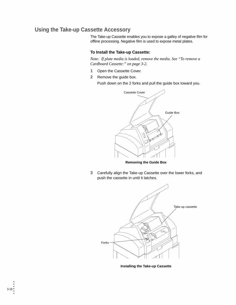
Using the Take-up Cassette AccessoryThe Take-up Cassette enables you to expose a galley of negative film for offline processing. Negative film is used to expose metal plates.
To Install the Take-up Cassette:
Note: If plate media is loaded, remove the media. See “To remove a Cardboard Cassette:” on page 3-2.
1 Open the Cassette Cover.
2 Remove the guide box.
Push down on the 2 forks and pull the guide box toward you.
Removing the Guide Box
3 Carefully align the Take-up Cassette over the lower forks, and push the cassette in until it latches.
Installing the Take-up Cassette
Cassette Cover
Guide Box
Take-up cassette
Forks

Operating Basics 3-19
• • • •••
Op
era
ting
Basic
s
4 Load an input cassette containing negative film. See “To load a cardboard cassette:” on page 3-6.
5 In the PrintersRIP®, configure a page setup and input channel for the Take-up Cassette. See the PrintersRIP® manual.
To remove the Take-up Cassette:
1 If the Take-up panel on the DPM Status Bar shows that the media in the Take-up cassette is uncut, click the lock to display the pop-up menu.
2 Select Eject takeup and wait for the lock to open.
3 Open the Cassette Cover.
4 Remove the Take-up Cassette.
Removing the Take-up Cassette
The media type must be plate for ON LINE processing (guide box) of cut plates.
5 Install an empty Take-up Cassette to continue in Take-up mode.
OR
Return to Processor mode. See “To return to Processor mode:” on page 3-19.
To return to Processor mode:
1 After the Take-up cassette has been removed, insert the guide box.
2 Load a input cassette containing plate media. See “Replacing Media” on page 3-2.
3 Close the top cover.
Cassette Cover
Take-up
Forks
3-20
• • • •••
Adjusting the Plate CatcherThe Plate Catcher, which is located on the back of the DPM, is where the processed plates will be delivered when using the in-line processor.
Each time you produce plates with a new length, the Plate Catcher must be adjusted to accept the length of media that will be produced.
NOTE: When producing plates of various lengths, best results can be obtained by batching plates with similar lengths (less than 10 cm / 4 inches difference).
To adjust the plate catcher:
1 Locate the Plate Catcher.
Located on the back of the DPM in the middle of the lower half of the equipment.
2 Will you be producing media of various lengths?
3 Adjust the Plate Catcher so that it is 2.5 cm (1") longer than the media length you will be producing.
Grasp the adjustable center slide, and extend it to the appropriate length.
4 Adjust the Plate Catcher so that it is 2.5 cm (1") longer than the longest media length you will be producing.
Grasp the adjustable center slide, and extend it to the appropriate length.
NO YES
Do Step 3 only. Skip to Step 4.
4-1 • • • •••
Chapter 4
• • • • • • Troubleshooting
The DPM utilizes a combination of proven imaging design, simple media path, and reliable processor technology. In the unlikely event that difficulty should arise in these areas, the procedures in this chapter will be valuable in resolving media related difficulties.
This chapter contains an explanation of Error Messages and Alerts as well as procedures for removing jams.
Error Messages and AlertsWhen malfunctions occur, you are alerted by:
• “Error Handler Messages”
• “Status Bar Error Indicators”
• “Device Dialog Errors”
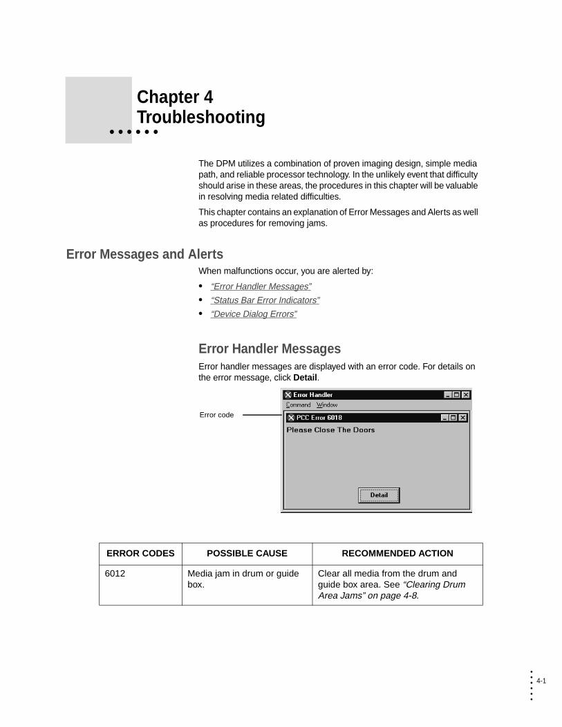
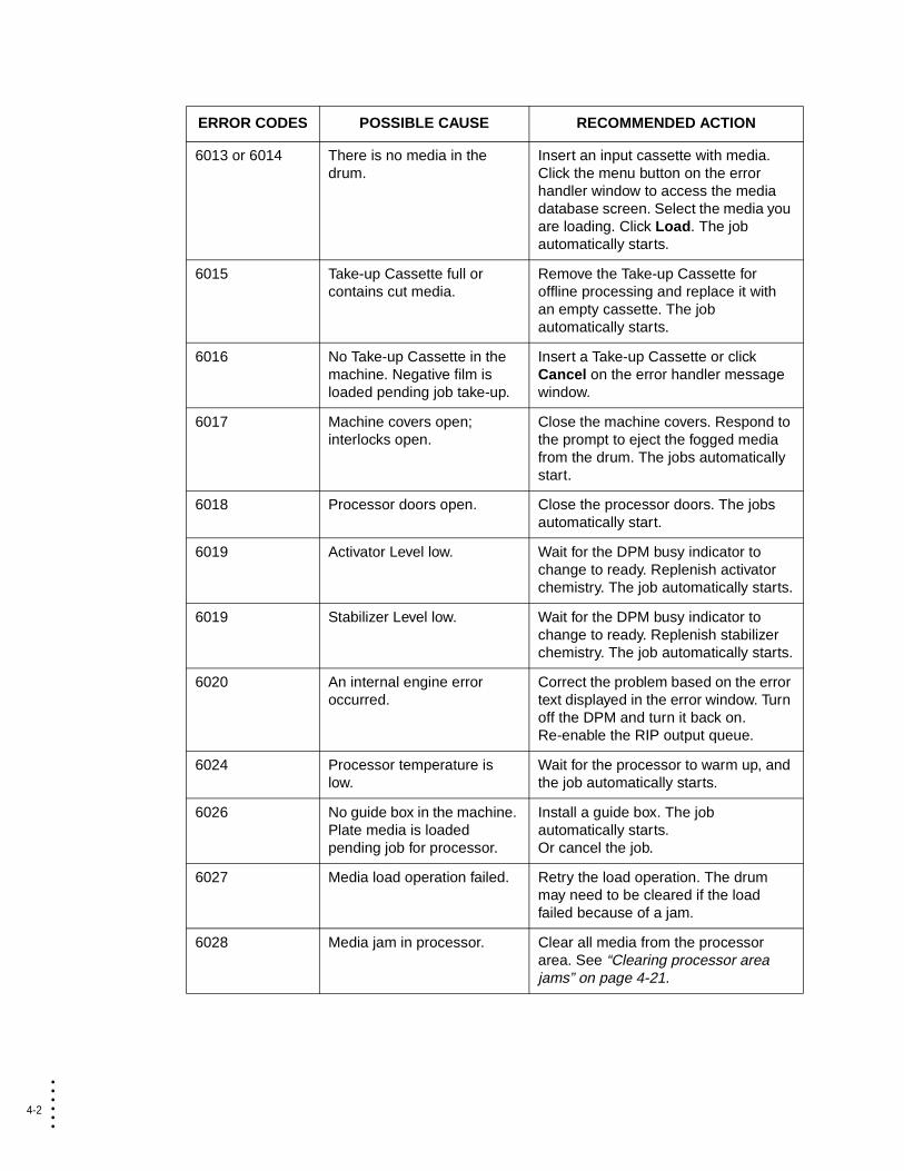
Error Handler MessagesError handler messages are displayed with an error code. For details on the error message, click Detail.
Error code
ERROR CODES POSSIBLE CAUSE RECOMMENDED ACTION
6012 Media jam in drum or guide box.
Clear all media from the drum and guide box area. See “Clearing Drum Area Jams” on page 4-8.
4-2
• • • •••
6013 or 6014 There is no media in the drum.
Insert an input cassette with media. Click the menu button on the error handler window to access the media database screen. Select the media you are loading. Click Load. The job automatically starts.
6015 Take-up Cassette full or contains cut media.
Remove the Take-up Cassette for offline processing and replace it with an empty cassette. The job automatically starts.
6016 No Take-up Cassette in the machine. Negative film is loaded pending job take-up.
Insert a Take-up Cassette or click Cancel on the error handler message window.
6017 Machine covers open; interlocks open.
Close the machine covers. Respond to the prompt to eject the fogged media from the drum. The jobs automatically start.
6018 Processor doors open. Close the processor doors. The jobs automatically start.
6019 Activator Level low. Wait for the DPM busy indicator to change to ready. Replenish activator chemistry. The job automatically starts.
6019 Stabilizer Level low. Wait for the DPM busy indicator to change to ready. Replenish stabilizer chemistry. The job automatically starts.
6020 An internal engine error occurred.
Correct the problem based on the error text displayed in the error window. Turn off the DPM and turn it back on. Re-enable the RIP output queue.
6024 Processor temperature is low.
Wait for the processor to warm up, and the job automatically starts.
6026 No guide box in the machine. Plate media is loaded pending job for processor.
Install a guide box. The job automatically starts.Or cancel the job.
6027 Media load operation failed. Retry the load operation. The drum may need to be cleared if the load failed because of a jam.
6028 Media jam in processor. Clear all media from the processor area. See “Clearing processor area jams” on page 4-21.
ERROR CODES POSSIBLE CAUSE RECOMMENDED ACTION

Troubleshooting 4-3
• • • •••
Tro
ub
lesh
oo
ting
Status Bar Error IndicatorsIcons displayed in the Status Bar indicate system error, such as when liquid levels are low.
DPM Status POSSIBLE CAUSE USER ACTION
Processor Activator level low. Wait for the DPM busy indicator to change to ready. Replenish activator chemistry. See “Filling the processor with chemicals” on page 5-5.
Processor Stabilizer level low. Wait for the DPM busy indicator to change to ready. Replenish stabilizer chemistry. See “Filling the processor with chemicals” on page 5-5.
No media in the drum. Load the material. See “Replacing Media” on page 3-2.
Material load operation failed. Retry the load operation. The drum may need to be cleared if the load failed because of a jam.
Processor temperature is low. Heater is on.
Wait for the processor to warm up.
Media jam in processor. Clear all media from the processor area. “Clearing processor area jams” on page 4-21.
There is cut media in the Take-up Cassette.
Remove the Take-up Cassette and replace it with an empty cassette.
*Icon flashes
No Take-up Cassette in the machine. Film media is loaded.
Install a Take-up Cassette or change the media loaded to plate and install a guide box.

4-4
• • • •••
*Icon flashes
No guide box. Plate media is loaded.
Install a guide box or change the material loaded to film and insert a Take-up Cassette.
Engine off or offline. Turn on the DPM. Enable outputs.
DPM Status POSSIBLE CAUSE USER ACTION
Troubleshooting 4-5
• • • •••
Tro
ub
lesh
oo
ting
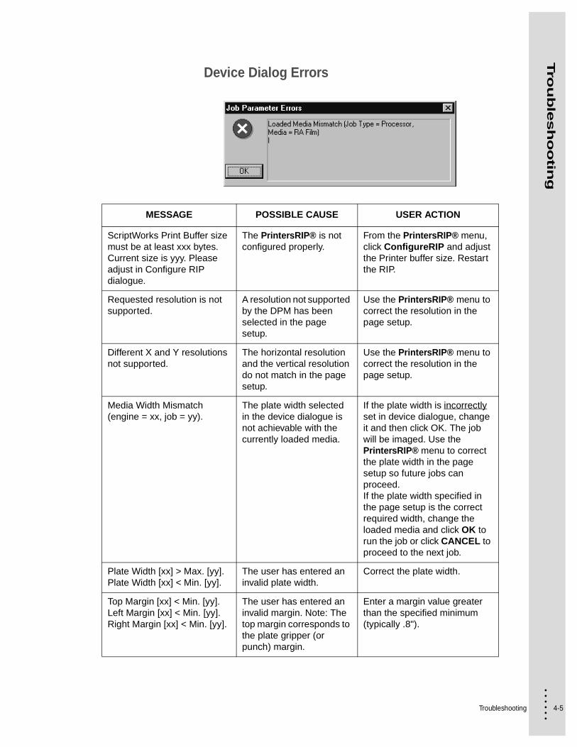
Device Dialog Errors
MESSAGE POSSIBLE CAUSE USER ACTION
ScriptWorks Print Buffer size must be at least xxx bytes. Current size is yyy. Please adjust in Configure RIP dialogue.
The PrintersRIP® is not configured properly.
From the PrintersRIP® menu, click ConfigureRIP and adjust the Printer buffer size. Restart the RIP.
Requested resolution is not supported.
A resolution not supported by the DPM has been selected in the page setup.
Use the PrintersRIP® menu to correct the resolution in the page setup.
Different X and Y resolutions not supported.
The horizontal resolution and the vertical resolution do not match in the page setup.
Use the PrintersRIP® menu to correct the resolution in the page setup.
Media Width Mismatch (engine = xx, job = yy).
The plate width selected in the device dialogue is not achievable with the currently loaded media.
If the plate width is incorrectly set in device dialogue, change it and then click OK. The job will be imaged. Use the PrintersRIP® menu to correct the plate width in the page setup so future jobs can proceed.If the plate width specified in the page setup is the correct required width, change the loaded media and click OK to run the job or click CANCEL to proceed to the next job.
Plate Width [xx] > Max. [yy].Plate Width [xx] < Min. [yy].
The user has entered an invalid plate width.
Correct the plate width.
Top Margin [xx] < Min. [yy].Left Margin [xx] < Min. [yy].Right Margin [xx] < Min. [yy].
The user has entered an invalid margin. Note: The top margin corresponds to the plate gripper (or punch) margin.
Enter a margin value greater than the specified minimum (typically .8").

4-6
• • • •••
Image Length [xx] > Min. [yy]. The image dimensions exceed the imageable area of this job.
Click OK to clip the image.Click CANCEL to proceed to next job (this job is moved to the held queue.Click DISABLE to disable the RIP queue and correct the problem at the desktop.
Media type mismatch. Job type: ProcessorMedia type: Negative film
The pending job is going to the processor but the media loaded is negative film.
Cancel to proceed to the next job. ORSelect Disable to stop the RIP queue and change the loaded media. ORChange the output destination and select OK to send the job to take-up.
Media type mismatch. Job type: Take-upMedia type: Plate media
The pending job is going to the Take-up Cassette but the media loaded is plate media.
Cancel to proceed to the next job. ORSelect Disable to stop the RIP queue and change the loaded media. ORChange the output destination and select OK to send the job to the processor.
MESSAGE POSSIBLE CAUSE USER ACTION

Troubleshooting 4-7
• • • •••
Tro
ub
lesh
oo
ting
Clearing JamsWhen media jams occur in the DPM, the following procedures will assist you in clearing the jams.
Identifying Troubleshooting AreasThere are three main areas where jams may occur—Drum area, Conveyor area and Processor area.
Jam Areas
PROCESSOR Area
MEDIA and DRUM Area
CONVEYOR Area

4-8
• • • •••
Clearing Drum Area JamsIf a media jam occurs in the drum area, error messages are displayed in the PrintersRIP® Window. To clear a media jam in this area of the DPM, perform the following jam clearance procedure.
To remove media jams from the drum:
1 Allow sufficient time for any jobs in the processor to finish.
Wait approximately 1 minute, or until the BUSY message is no longer illuminated, before doing this procedure.
BUSY message
2 Turn off the power switch on the back of the DPM.
3 Open the cassette cover.
ERROR
TAKE-UP
ON LINE
BUSY
ON
EJECT LOAD UNLOAD
Troubleshooting 4-9
• • • •••
Tro
ub
lesh
oo
ting
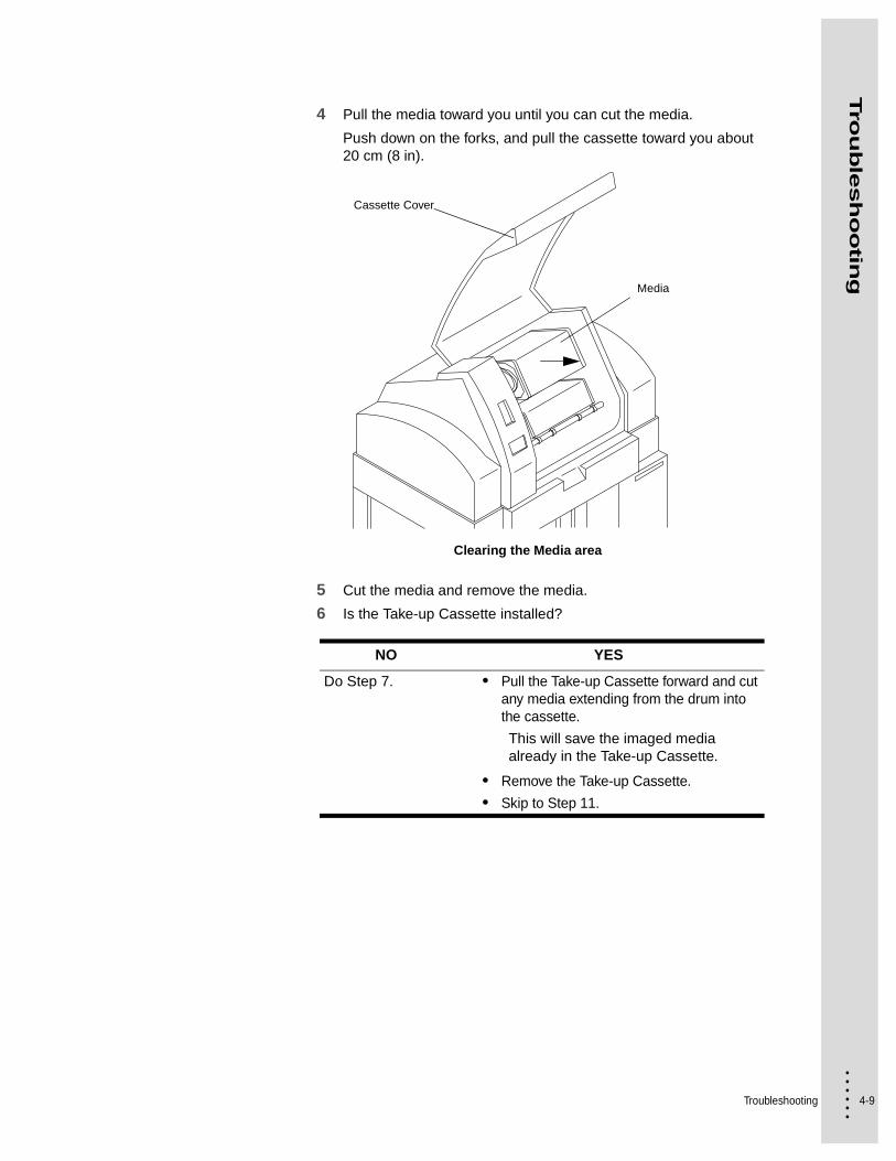
4 Pull the media toward you until you can cut the media.
Push down on the forks, and pull the cassette toward you about 20 cm (8 in).
Clearing the Media area
5 Cut the media and remove the media.
6 Is the Take-up Cassette installed?
NO YES
Do Step 7. • Pull the Take-up Cassette forward and cut any media extending from the drum into the cassette.
This will save the imaged media already in the Take-up Cassette.
• Remove the Take-up Cassette.
• Skip to Step 11.
Media
Cassette Cover

4-10
• • • •••
7 Pull the guide box toward you and check for media extending through the guide box and into the conveyor area.
Push down on the forks, and pull the guide box toward you.
Clearing the Media area
8 Has the media extended into the conveyor area?
NO YES
Skip to Step 10. Do Step 9.
Cassette Cover
Guide Box or Take-Up Cassette
Troubleshooting 4-11
• • • •••
Tro
ub
lesh
oo
ting
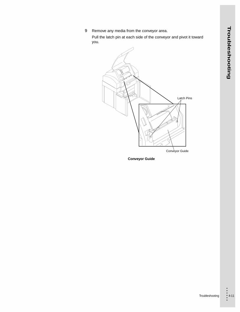
9 Remove any media from the conveyor area.
Pull the latch pin at each side of the conveyor and pivot it toward you.
Conveyor Guide
Conveyor Guide
Latch Pins

4-12
• • • •••
10 Remove the guide box, or (if installed) the Take-up Cassette Accessory.
Push down on the forks, and pull the guide box toward you.
Removing the Guide Box or Take-up Cassette
11 Remove the upper light shield.
Pivot the latch levers inward, and slide the light shield forward until they clear the forks.
12 Remove the lower light shield
Pivot the latch levers inward, and slide the light shield forward until they clear the forks.
Cassette Cover
Guide Box or Take-up Cassette
Forks
Troubleshooting 4-13
• • • •••
Tro
ub
lesh
oo
ting
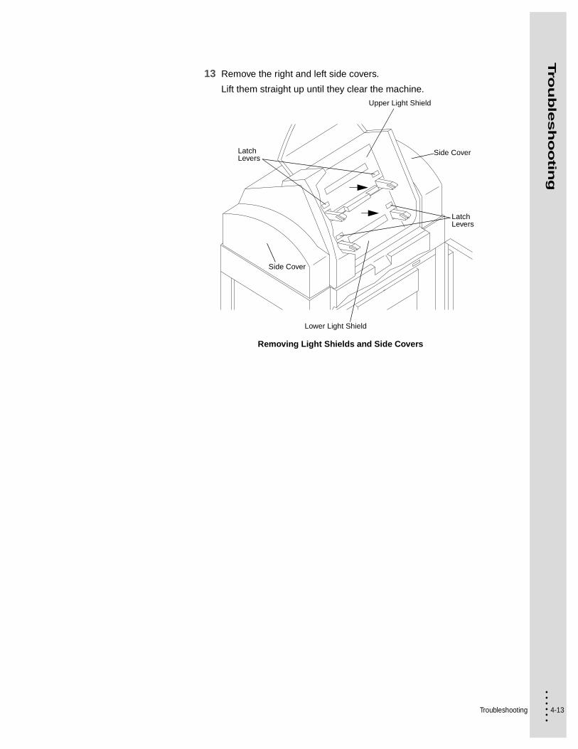
13 Remove the right and left side covers.
Lift them straight up until they clear the machine.
Removing Light Shields and Side Covers
Side Cover
Upper Light Shield
Latch Levers
Lower Light Shield
Latch Levers
Side Cover

4-14
• • • •••
The DPM will not restart if any pieces of media remain in the drum area.
14 Remove all media from the drum.
15 Check the media path through the drum. Are there large folds of media caught in the path?
Drum Area Media Path
NO YES
Skip to Step 17. The media must be carefully removed. See Step 16.
Feed Rollers
Output Rollers
MEDIA
GUIDE BOX
DRUM
Conveyor Rollers
Buffer Rollers
Knife
GUIDE HOOP
Input Rollers
Troubleshooting 4-15
• • • •••
Tro
ub
lesh
oo
ting
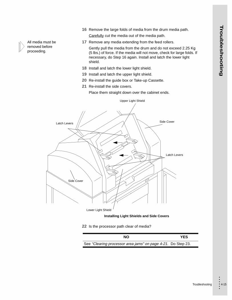
16 Remove the large folds of media from the drum media path.
Carefully cut the media out of the media path.
All media must be removed before proceeding.
17 Remove any media extending from the feed rollers.
Gently pull the media from the drum and do not exceed 2.25 Kg (5 lbs.) of force. If the media will not move, check for large folds. If necessary, do Step 16 again. Install and latch the lower light shield.
18 Install and latch the lower light shield.
19 Install and latch the upper light shield.
20 Re-install the guide box or Take-up Cassette.
21 Re-install the side covers.
Place them straight down over the cabinet ends.
Installing Light Shields and Side Covers
22 Is the processor path clear of media?
Side Cover
Side Cover
Upper Light Shield
Latch Levers
Lower Light Shield
Latch Levers
NO YES
See “Clearing processor area jams” on page 4-21. Do Step 23.
4-16
• • • •••
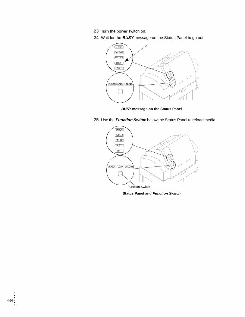
23 Turn the power switch on.
24 Wait for the BUSY message on the Status Panel to go out.
BUSY message on the Status Panel
25 Use the Function Switch below the Status Panel to reload media.
Status Panel and Function Switch
ERROR
TAKE-UP
ON LINE
BUSY
ON
EJECT LOAD UNLOAD
ERROR
TAKE-UP
ON LINE
BUSY
ON
EJECT LOAD UNLOAD
Function Switch

Troubleshooting 4-17
• • • •••
Tro
ub
lesh
oo
ting
26 From PrintersRIP®, select DPM 2340 > Output > Output Controller/Monitor.
27 De-select the disable outputs.
Click on the 3 for disable outputs.
Enable outputs in PrintersRip®
Clearing media jams during loadIf the media fails to load properly, error messages are generated in the PrintersRIP® Window indicating the existence of a jam.
To clear a media loading jam:
1 Allow sufficient time for any jobs in the processor to finish.
Wait approximately 1 minute, or until the BUSY message is no longer illuminated, before doing this procedure.
BUSY message
2 Turn off the power switch on the back of the DPM.
3 Open the cassette cover.
4 Remove the media and slowly pull it toward you.
ERROR
TAKE-UP
ON LINE
BUSY
ON
EJECT LOAD UNLOAD
4-18
• • • •••
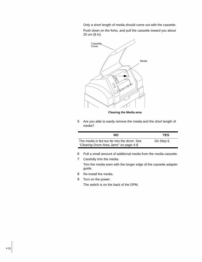
Only a short length of media should come out with the cassette.
Push down on the forks, and pull the cassette toward you about 20 cm (8 in).
Clearing the Media area
5 Are you able to easily remove the media and the short length of media?
6 Pull a small amount of additional media from the media cassette.
7 Carefully trim the media.
Trim the media even with the longer edge of the cassette adapter guide.
8 Re-install the media.
9 Turn on the power.
The switch is on the back of the DPM.
NO YES
The media is fed too far into the drum. See “Clearing Drum Area Jams” on page 4-8.
Do Step 6.
Media
Cassette Cover

Troubleshooting 4-19
• • • •••
Tro
ub
lesh
oo
ting
10 Wait for the processor unit to warm up.
The BUSY message turns off.
BUSY message on the Status Panel
11 Load the media.
Push the LOAD button on the Status Panel to load the media.
LOAD Button on the Status Panel
ERROR
TAKE-UP
ON LINE
BUSY
ON
EJECT LOAD UNLOAD
ERROR
TAKE-UP
ON LINE
BUSY
ON
EJECT LOAD UNLOAD
4-20
• • • •••
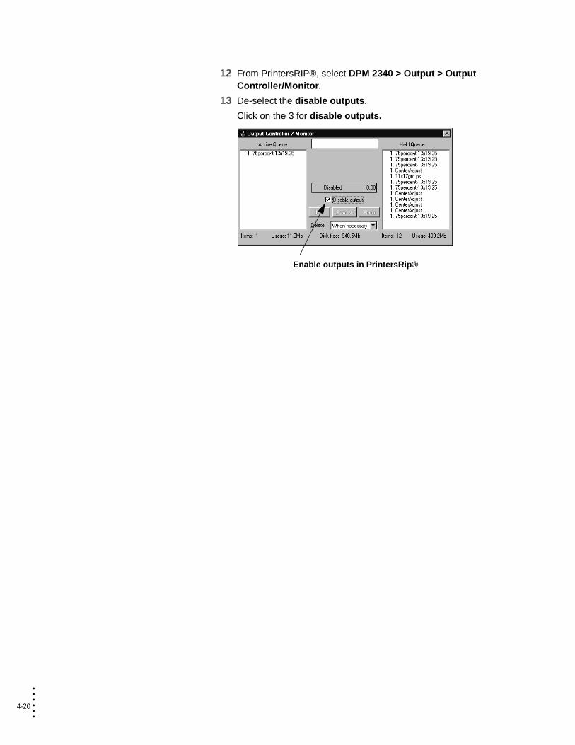
12 From PrintersRIP®, select DPM 2340 > Output > Output Controller/Monitor.
13 De-select the disable outputs.
Click on the 3 for disable outputs.
Enable outputs in PrintersRip®
Troubleshooting 4-21
• • • •••
Tro
ub
lesh
oo
ting
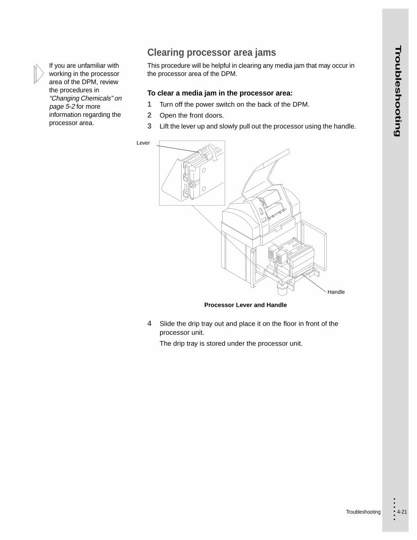
Clearing processor area jamsIf you are unfamiliar with working in the processor area of the DPM, review the procedures in “Changing Chemicals” on page 5-2 for more information regarding the processor area.
This procedure will be helpful in clearing any media jam that may occur in the processor area of the DPM.
To clear a media jam in the processor area:
1 Turn off the power switch on the back of the DPM.
2 Open the front doors.
3 Lift the lever up and slowly pull out the processor using the handle.
Processor Lever and Handle
4 Slide the drip tray out and place it on the floor in front of the processor unit.
The drip tray is stored under the processor unit.
Handle
Lever

4-22
• • • •••
5 Remove any media that has become jammed in the conveyor path. If necessary, see “Clearing conveyor area jams” on page 4-27 for more information.
Conveyor Guide
Never remove media by pulling it backwards. This will contaminate the input rollers and require you to clean the input guide and rollers.
6 Remove any media that is jammed in the processor.
Unlatch the input guide and pivot it toward you and pull the media forward through the rollers.
Opening the Input Guide
7 Remove any media that is in the activator rack.
Unlatch and remove the rack. If necessary, remove the activator guide.
Lower Conveyor Guide
Latch Pins
Cassette Cover
Front Door
Front Door
Upper Conveyor Guide
Input Guide

Troubleshooting 4-23
• • • •••
Tro
ub
lesh
oo
ting
8 Remove any media that is in the stabilizer rack.
Unlatch and remove the rack. If necessary, remove the stabilizer guide.
Unlatching the Processor Racks
9 Check that the exit guides are clear of media.
These are located above the plate catcher.
10 Clean any guides that are dirty and may have contributed to the jam.
If necessary, see “Cleaning the processor unit” on page 5-7 for information about any guide you may need to clean.
Disassembling the Processor Racks
LatchStabilizer RackActivator Rack
Thumb Screw
Guide

4-24
• • • •••
The pin on the rack must be aligned with the slot in the tank.
11 Install the stabilizer rack into the stabilizer tank and the activator rack into the activator tank.
Installing the Processor Racks
12 Ensure that the gears on each rack are engaged.
You will not be able to latch the racks if the gears are not engaged correctly.
13 Latch each rack.
Latching the Processor Racks
Stabilizer Rack Activator Rack
Latch

Troubleshooting 4-25
• • • •••
Tro
ub
lesh
oo
ting
14 Close and latch the processor input guide.
Latching the Input Guide
15 Install the drip tray.
16 Push the processor unit into the DPM until it latches.
17 Close the front doors.
Front Doors
18 Turn on the power.
The switch is on the back of the DPM.
Input Guide
Input Guide LatchProcessor Frame
Front Doors

4-26
• • • •••
19 Wait for the processor unit to warm up.
The BUSY message turns off.
BUSY message on the Status Panel
20 From PrintersRIP®, select DPM 2340 > Output > Output Controller/Monitor.
21 De-select the disable outputs.
Click on the 3 for disable outputs.
Enable outputs in PrintersRip®
ERROR
TAKE-UP
ON LINE
BUSY
ON
EJECT LOAD UNLOAD
Troubleshooting 4-27
• • • •••
Tro
ub
lesh
oo
ting
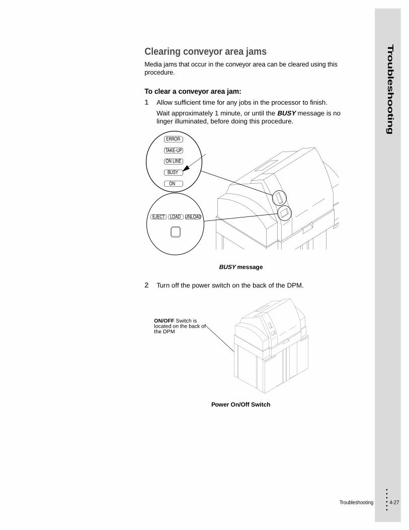
Clearing conveyor area jamsMedia jams that occur in the conveyor area can be cleared using this procedure.
To clear a conveyor area jam:
1 Allow sufficient time for any jobs in the processor to finish.
Wait approximately 1 minute, or until the BUSY message is no linger illuminated, before doing this procedure.
BUSY message
2 Turn off the power switch on the back of the DPM.
Power On/Off Switch
ERROR
TAKE-UP
ON LINE
BUSY
ON
EJECT LOAD UNLOAD
ON/OFF Switch is located on the back of the DPM

4-28
• • • •••
3 Open the cassette cover.
4 Open the front doors.
Cassette Cover and Front Doors
Front Doors
Cassette Cover
Troubleshooting 4-29
• • • •••
Tro
ub
lesh
oo
ting
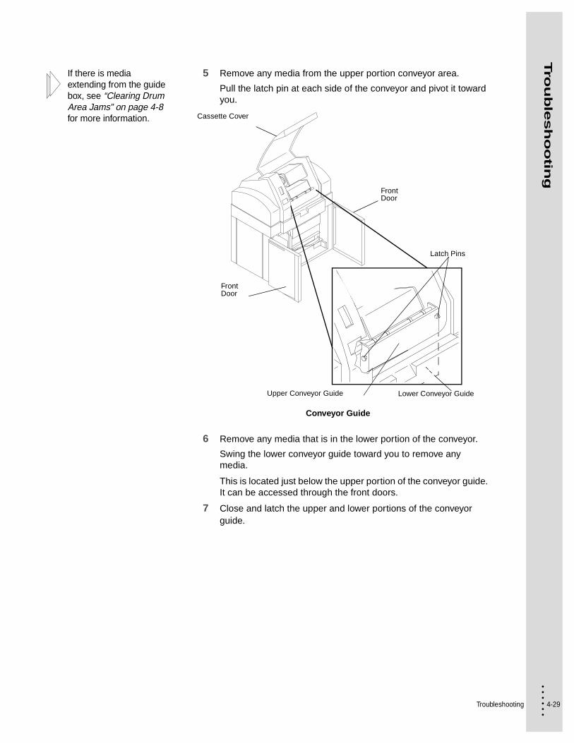
If there is media extending from the guide box, see “Clearing Drum Area Jams” on page 4-8 for more information.
5 Remove any media from the upper portion conveyor area.
Pull the latch pin at each side of the conveyor and pivot it toward you.
Conveyor Guide
6 Remove any media that is in the lower portion of the conveyor.
Swing the lower conveyor guide toward you to remove any media.
This is located just below the upper portion of the conveyor guide. It can be accessed through the front doors.
7 Close and latch the upper and lower portions of the conveyor guide.
Lower Conveyor Guide
Latch Pins
Cassette Cover
Front Door
Front Door
Upper Conveyor Guide
4-30
• • • •••
If there is media jammed in the processor, see “Clearing processor area jams” on page 4-21 for more information.
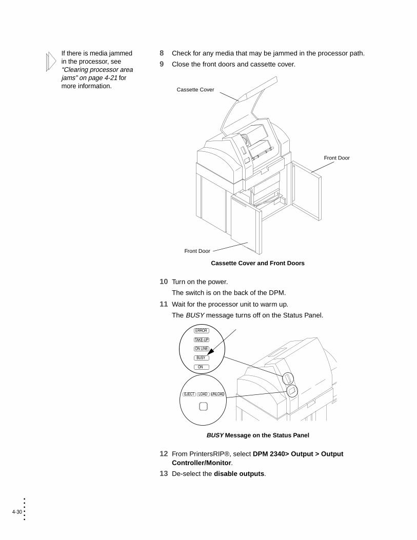
8 Check for any media that may be jammed in the processor path.
9 Close the front doors and cassette cover.
Cassette Cover and Front Doors
10 Turn on the power.
The switch is on the back of the DPM.
11 Wait for the processor unit to warm up.
The BUSY message turns off on the Status Panel.
BUSY Message on the Status Panel
12 From PrintersRIP®, select DPM 2340> Output > Output Controller/Monitor.
13 De-select the disable outputs.
Cassette Cover
Front Door
Front Door
ERROR
TAKE-UP
ON LINE
BUSY
ON
EJECT LOAD UNLOAD
Troubleshooting 4-31
• • • •••
Tro
ub
lesh
oo
ting
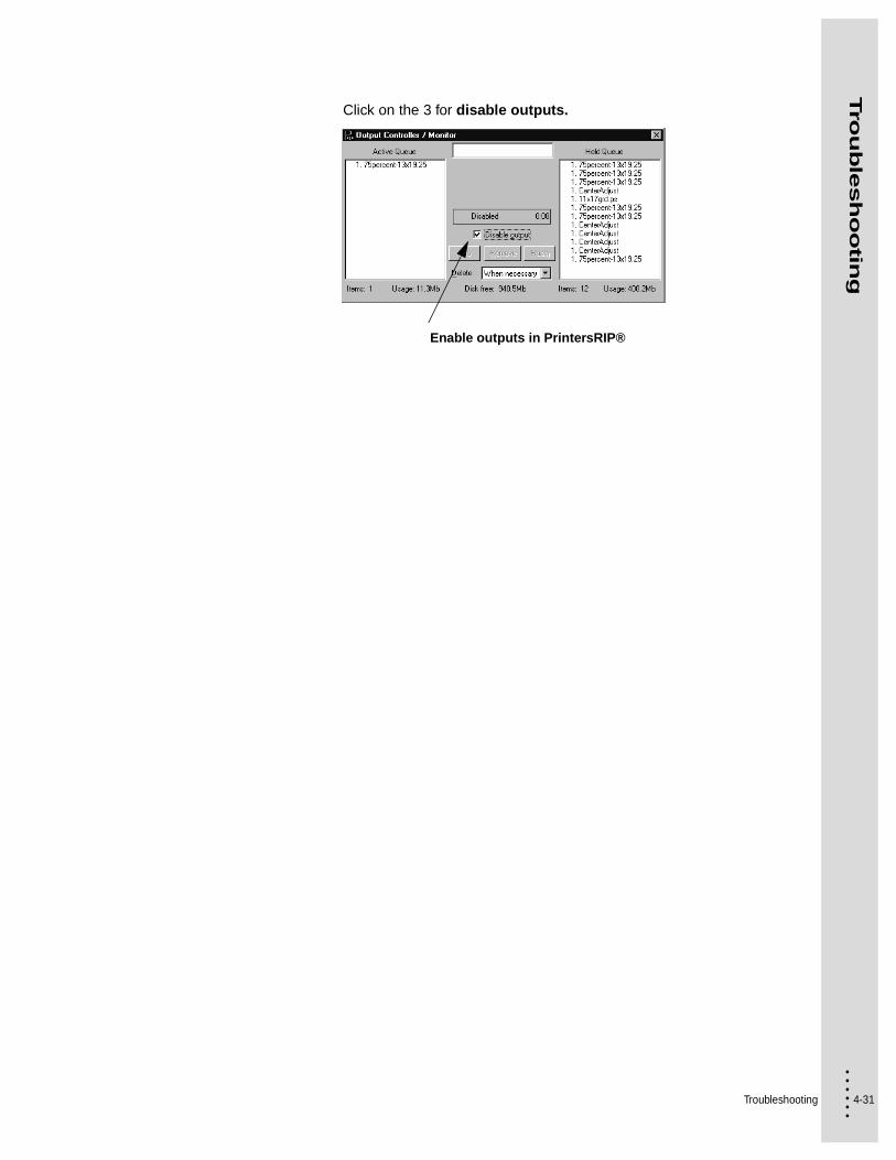
Click on the 3 for disable outputs.
Enable outputs in PrintersRIP®

4-32
• • • •••

5-1 • • • •••
Chapter 5
• • • • • • Maintaining the DPM
Your DPM has been designed to deliver consistent high quality output. To ensure that the outstanding imaging results you have become accustomed to are not degraded, a few maintenance activities are required.
This chapter details those procedures that should be performed.
Servicing the DPM QuarterlyThe DPM requires cleaning and lubrication by an authorized ABDick service technician every 3 months. Contact the authorized service organization in your area to schedule this.
Changing the Air FilterThe air filter, 2340-AF, must be changed every 3 months to ensure that dust does not contaminate the imaging area, and that sufficient air flow is maintained in the drum area.
To change the air filter:
1 Turn the platemaker off.
2 Open the filter cover and remove the air filter.
3 Install a new filter, 2340-AF with the metal mesh down, and close the cover.
Changing the Air Filter
Filter Cover
ON/OFF Switch is located on the back of the DPM
5-2
• • • •••
Changing ChemicalsImportant: To obtain optimum results with your new chemicals, you should also clean the processor unit at the same time you change chemicals. The activator filter element should also be changed every month.
Draining chemicals
To drain the chemicals:
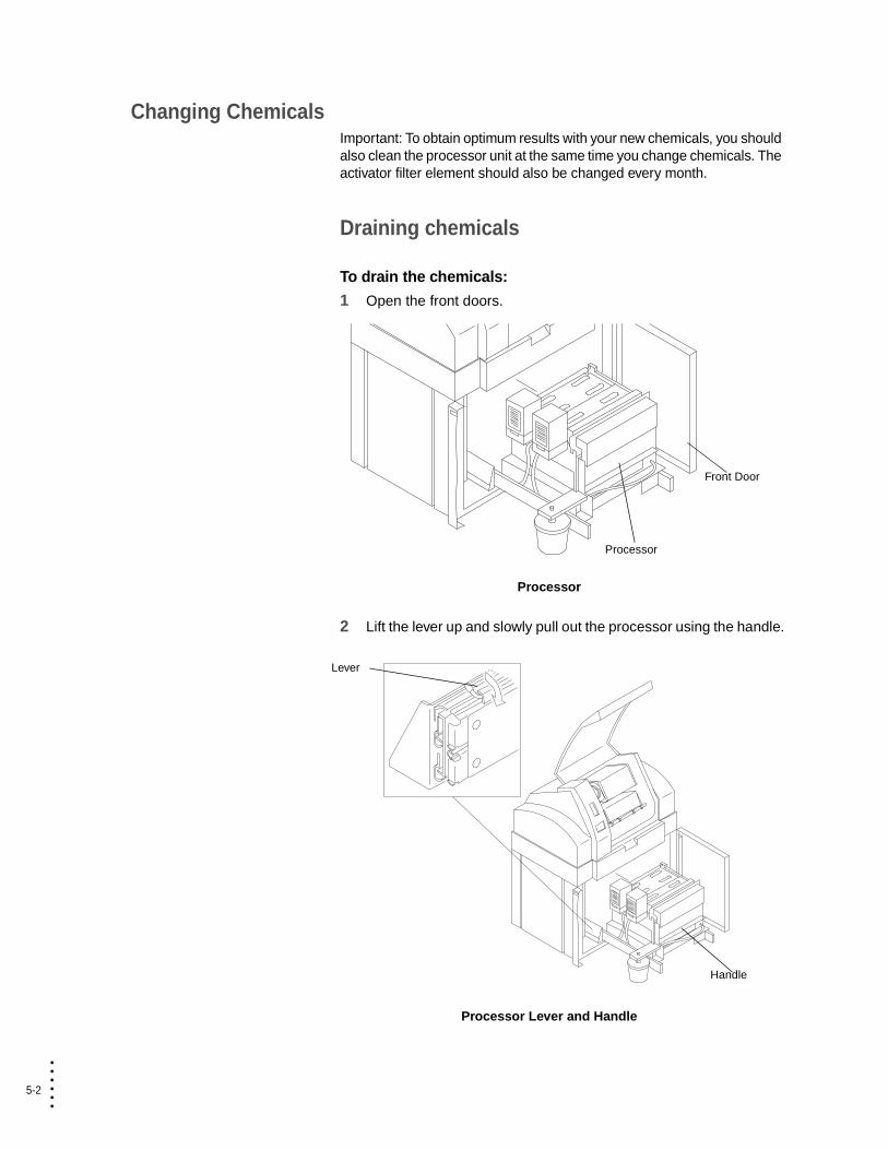
1 Open the front doors.
Processor
2 Lift the lever up and slowly pull out the processor using the handle.
Processor Lever and Handle
Processor
Front Door
Handle
Lever

Maintaining the DPM 5-3
• • • •••
Main
tain
ing
the D
PM
3 Remove the chemistry replenisher bottles.
Locating the Replenisher Bottles
Do not allow each tank to drain unattended.
4 Place a bucket under the side of the processor unit.
5 Locate the drain hoses on the side of the processor. Place the end of the stabilizer drain hose in the bucket.
The hose toward the back of the processor is the stabilizer drain hose.
Replenisher Bottles

5-4
• • • •••
6 Turn the lever to open the hose valve.
The stabilizer chemistry will drain from the tank into the bucket.
Draining the Processor Tanks
7 When the tank is empty, turn the lever to close the hose valve.
WARNING! Obey all laws regarding disposal of chemicals in your area.
8 Return the hose to its original position and empty the bucket.
9 Repeat Steps 4 - 8 to drain the activator tank.
10 Push the red button on the filter.
The pressure in the system must be released before opening the filter assembly.
11 Place a bucket under the activator filter canister.
The filter is full of activator chemicals.
12 Carefully unscrew the activator filter canister.
Draining the Filter Canister
Valve Activator Hose
Processor Unit
Stabilizer Hose
Activator Filter Canister
Bucket
Red Button

Maintaining the DPM 5-5
• • • •••
Main
tain
ing
the D
PM
Replace the activator filter every month for the Quicksilver products.
Replace the activator filter element every month, or every chemical change with the MEGAPRO® products.
13 Drain the filter canister.
Tip the canister to drain the chemicals.
14 Re-assemble the filter taking care not to cross-thread the canister.
15 Always clean the processor when changing chemistry. See “Cleaning the processor unit” on page 5-7 in this Chapter.
Filling the processor with chemicals
To fill the processor with chemicals:
No mixing is required for the Quicksilver products.
If mixing is required, do not pour chemicals and water separately into the tanks. This will not result in proper mixing.
Each tank holds 5.0 gallons (19 liters) of chemistry. An additional 2 quarts (1.9 liters) is for the replenishment bottles.
Always have the rack assemblies in position before filling the unit with chemistry.
1 Read the label on the chemical bottles to determine if mixing is required. Follow mixing instructions when required.
2 Check that both drain hose valves are closed.
Closing Drain Hose Valves
3 Pour the solution into the filling spout of the tank (where the replenisher bottle was removed). Be careful to pour solution into the correct tank. Tanks are labeled on the outside. Fill until the chemical level reaches the base of the filling spout. Don’t overfill.
ValveDrain Hoses

5-6
• • • •••
4 Fill the replenisher bottle and install the feeder cap. Insert the replenisher bottle into the filling spout with the label facing out.
Refill the replenisher bottles as needed.
The replenisher bottle will add chemistry to the tanks bringing it to the proper fluid level.
Filling Tanks and Replenisher Bottles
5 Rinse the mixing container and stirring stick, if necessary.
6 Have both tanks been filled?
7 Gently push the processor unit into the DPM.
Be careful to avoid spilling the chemicals.
8 Close the front doors.
9 Wait for the processor unit to warm up before beginning operation.
The platemaker will not operate until it has reached operating temperature (15 - 20 minutes).
NO YES
Repeat Steps 1 - 6 to mix the other chemical solution and fill the other tank.
Do Step 7.
Filling SpoutReplenisher Bottle and Label
Maintaining the DPM 5-7
• • • •••
Main
tain
ing
the D
PM
Cleaning the processor unitCleaning should be performed after 1875 square feet (172.5 m2) or 4 weeks (whichever comes first) with MEGAPRO® products.
Cleaning should be performed after 1400 square feet (130 m2) or 3 weeks for the Quicksilver products.
Failure to properly clean the processor on a timely basis can result in improper processing, scratches on plates, jams, and reduced chemical life. Since you must change your chemicals at the same time, you should clean the processor unit every time you change chemicals. The processor unit also includes a filter, 2340-PF, to remove particles from the activator chemistry. This filter should be changed every month, or with every activator chemical change with MEGAPRO® products, and every month for the Quicksilver products.
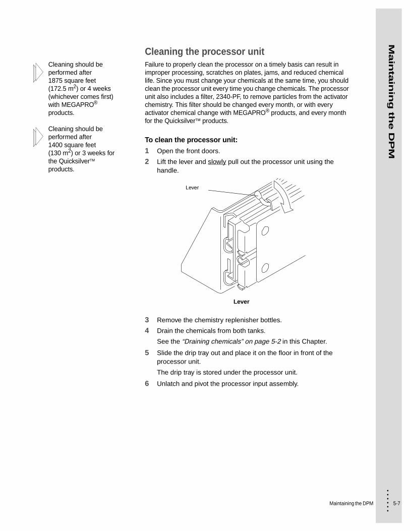
To clean the processor unit:
1 Open the front doors.
2 Lift the lever and slowly pull out the processor unit using the handle.
Lever
3 Remove the chemistry replenisher bottles.
4 Drain the chemicals from both tanks.
See the “Draining chemicals” on page 5-2 in this Chapter.
5 Slide the drip tray out and place it on the floor in front of the processor unit.
The drip tray is stored under the processor unit.
6 Unlatch and pivot the processor input assembly.
Lever
5-8
• • • •••
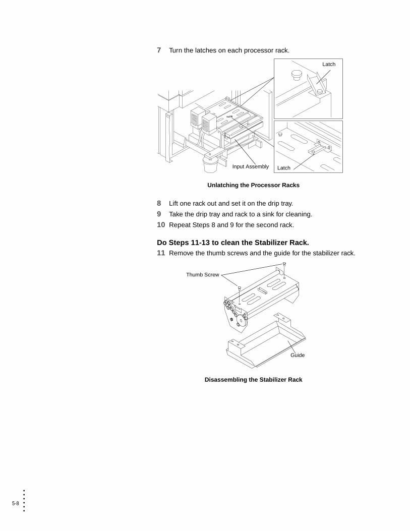
7 Turn the latches on each processor rack.
Unlatching the Processor Racks
8 Lift one rack out and set it on the drip tray.
9 Take the drip tray and rack to a sink for cleaning.
10 Repeat Steps 8 and 9 for the second rack.
Do Steps 11-13 to clean the Stabilizer Rack.11 Remove the thumb screws and the guide for the stabilizer rack.
Disassembling the Stabilizer Rack
Latch
Input Assembly Latch
Guide
Thumb Screw

Maintaining the DPM 5-9
• • • •••
Main
tain
ing
the D
PM
Do not use abrasive materials such as sanding cloth or scouring pads on any rollers or guide.
12 Clean the racks, guide, and 6 rollers with clean, warm water.
Rollers and guide should be cleaned with isopropyl alcohol and a cotton pad.
Polish all of the stainless steel guides with a high quality metal polish.
Rollers and Paddle Wheels
13 Install the guides back onto the racks making sure the “V” in the tab is aligned correctly with the pin in the rack.
Re-assembling the Stabilizer Rack
Paddle Wheels
2 Rollers
4 Rollers
"V" Groove
5-10
• • • •••
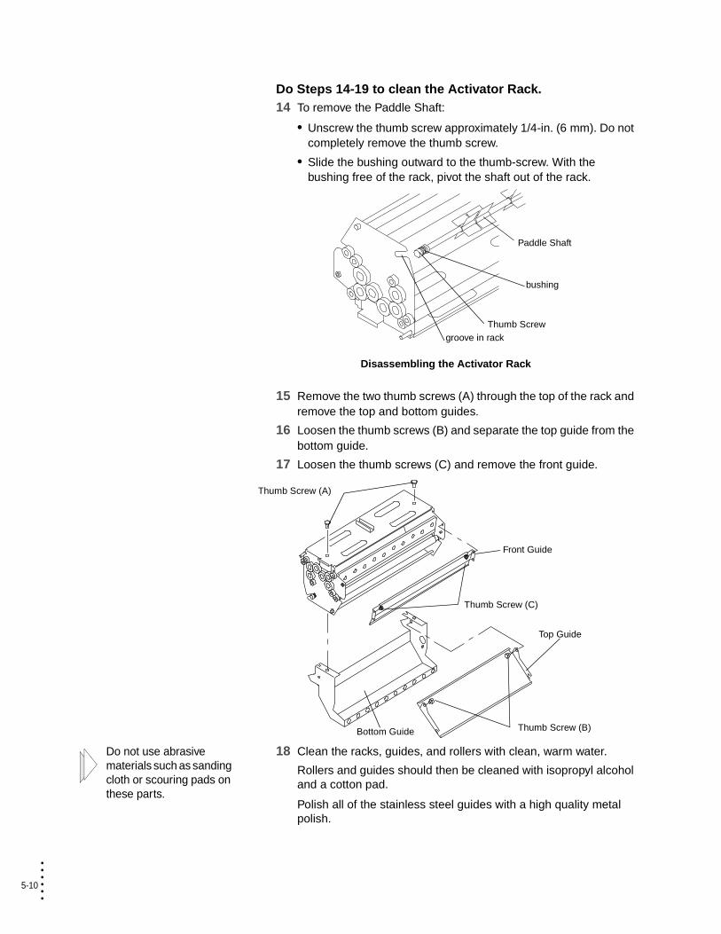
Do Steps 14-19 to clean the Activator Rack.14 To remove the Paddle Shaft:
• Unscrew the thumb screw approximately 1/4-in. (6 mm). Do not completely remove the thumb screw.
• Slide the bushing outward to the thumb-screw. With the bushing free of the rack, pivot the shaft out of the rack.
Disassembling the Activator Rack
15 Remove the two thumb screws (A) through the top of the rack and remove the top and bottom guides.
16 Loosen the thumb screws (B) and separate the top guide from the bottom guide.
17 Loosen the thumb screws (C) and remove the front guide.
Do not use abrasive materials such as sanding cloth or scouring pads on these parts.
18 Clean the racks, guides, and rollers with clean, warm water.
Rollers and guides should then be cleaned with isopropyl alcohol and a cotton pad.
Polish all of the stainless steel guides with a high quality metal polish.
Paddle Shaft
Thumb Screw
bushing
groove in rack
Top Guide
Front Guide
Thumb Screw (C)
Thumb Screw (A)
Thumb Screw (B)Bottom Guide

Maintaining the DPM 5-11
• • • •••
Main
tain
ing
the D
PM
19 Install the top guide into the bottom guide. Then, install the top, bottom and front guides back onto the racks making sure the “V” groove in the lower guide tab is aligned correctly with the pin in the rack.
Re-assembling the Activator Rack
20 Install the paddle shaft:
• Holding the bushing and the thumb screw at the end of the shaft, pivot the shaft into the groove of the rack.
• Seat the bushing in the groove of the rack.
• Tighten the thumb screw.
Installing the Paddle Shaft in the Activator Rack
21 Rinse the tanks with warm water. Drain the tanks using the drain hoses and a bucket.
22 Wipe the tanks dry with a clean cloth.
"V" Groove
Bottom Guide
Top Guide
Front Guide
Paddle Shaft
Thumb Screw
bushing
groove in rack

5-12
• • • •••
The pin on the rack must be aligned with the slot in the tank.
23 Install the stabilizer rack into the stabilizer tank and the activator rack into the activator tank.
Installing the Processor Racks
24 Ensure that the gears on each rack are engaged.
You will not be able to latch the racks if the gears are not engaged correctly.
25 Latch each rack.
Latching the Processor Racks
Stabilizer Rack Activator Rack
Latch

Maintaining the DPM 5-13
• • • •••
Main
tain
ing
the D
PM
26 Is the input guide clean?
The processor input guide does not need to be cleaned every time the chemistry is changed. Cleaning is only necessary if a residue builds up on the guide.
27 Remove the 2 thumb screws on the processor input guide.
28 Lift the guide out.
Removing the Input Assembly Guide
29 Clean the guide you removed and the one in the DPM.
30 Install the guide using the 2 thumb screws.
Assembling the Input Assembly Guide
NO YES
Do Steps 27 - 30. Skip to Step 31.
Input Assembly
Guide
Thumb Screw (2)
Guide
Input AssemblyThumb Screw (2)
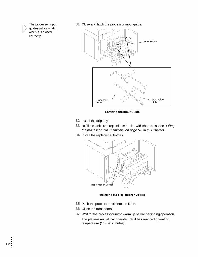
5-14
• • • •••
The processor input guides will only latch when it is closed correctly.
31 Close and latch the processor input guide.
Latching the Input Guide
32 Install the drip tray.
33 Refill the tanks and replenisher bottles with chemicals. See “Filling the processor with chemicals” on page 5-5 in this Chapter.
34 Install the replenisher bottles.
Installing the Replenisher Bottles
35 Push the processor unit into the DPM.
36 Close the front doors.
37 Wait for the processor unit to warm up before beginning operation.
The platemaker will not operate until it has reached operating temperature (15 - 20 minutes).
Input Guide
Input Guide Latch
Processor Frame
Replenisher Bottles

Appendix
Supporting Applications
For assistance in the operation of the DPM, consult the ABDick I.Q. Knowledge Database online (www.abdick.com) or contact the Digital Prepress Support Center at (888) 787-7222 in the United States.
Locating Authorized ABDick International Subsidiaries
Canada ABDick Company of Canada, Ltd.94 Brockport DriveRexdale, Ontario M9W 5C5Telephone: (416) 675-3933Fax: (416) 675-6986
United Kingdom ABDick Ltd.Great West Trading Estate983 Great West RoadBrentford, MiddlesexEngland TW8 9DNTelephone: 44 20 8326 1200Fax: 44 20 8326 1201
Locating Authorized ABDick International Regional Offices
Europe, Africa, and Near East ABDick Ltd.European Distributor GroupGreat West Trading Estate983 Great West RoadBrentford, MiddlesexEngland TW8 9DNTelephone: 44 20 8326 1200Fax: 44 20 8326 1201
Latin America and Caribbean Region 7400 Caldwell Ave.Niles, IL 60714Telephone: (772) 785-9157Fax: (772) 878-8069
Pacific and Far East Region 7400 Caldwell Ave.Niles, IL 60714Telephone: (847) 647-2491Fax: (847) 647-6940
A-1

A-2
• • • •••
A-3
• • • •••
Ap
pen
dix
A
Important Safety Warnings• Before attempting to operate the platemaker, be certain that each
operator has read this guide and is thoroughly familiar with the operating instructions and safety warnings.
• Always unplug the machine before undertaking repair, service, or maintenance.
• Read and heed all warning labels.
• Do not modify the unit, remove guards, covers, etc. and/or attempt to defeat any interlock switches. Under no circumstances attempt to operate the machine without all safety covers, interlocks, and other safety devices in their original, factory-installed condition.
• Obey all laws concerning the disposal of developing and processing chemicals, and other substances, in your area.
• ABDick recommends that repair and serving of your machine be performed only by a qualified ABDick service representative or an authorized dealer/distributor. Repair or servicing of the equipment by owners, operators, or unauthorized service personnel is not advised due to safety risks posed and the possibility of voiding applicable warranty coverage.
• Do not overfill the chemical tanks (see filling instructions). Be careful to avoid spillage of chemicals when filling and when sliding the processor unit in and out of the machine.
• Under no circumstances are the door or cover interlocks to be defeated.
CLASS I LASER PRODUCTaccording to EN 60825-1:1994
CAUTION
Adjustments or performance of procedures other than those specified herein may result in hazardous radiating exposure.

A-4
• • • •••
I-1 • • • •••
• • • • • • Index
AABDick A-1accuracy 1-6adjusting
exposure 3-13image centering 3-15plate length 3-14
air filter 5-1ambient temperature 1-7auto feed 2-11auto logon 2-11
Bbutton bar 2-7
Ccardboard cassettes, changing 3-2cassette adapter guide
attaching 3-6location 3-5
cassettes 3-1changing
air filter 5-1cardboard cassettes 3-2media type 3-12reloadable cassettes 3-8
chemicalsadding 5-5changing 5-2draining 5-2
cleaning the processor 5-7closing software programs 2-18contacting ABDick A-1conventions 1-2conveyor area jams 4-27current 1-7
Ddata interface 1-7database 2-13–2-14defining media type 3-12description of operation 2-2device dialog messages 4-5dimensions 1-7
disconnect device 1-3dongle 2-6DPM status bar, See status bardrum area jams 4-8
Eeject media 2-14eject timer 2-11electrical requirements 1-3end caps
attaching 3-6location 3-5
error messagesdevice dialog 4-5handler 4-1
exposureadjusting 3-13speed 1-6
Ffilling the processor 5-5function switch 2-5fuses 1-3
Ggalley leader, Take-up cassette 2-12ground 1-3guide box 3-18
Hhelp 2-7
Iimage centering 3-15imaging area 1-6imaging engine
setting preferences 2-11input cassette 3-9
replacing 3-2–3-13inserting
take-up cassette 3-18installing
platemaker 1-3
I-2
• • • •••
interlock switches 1-4
Jjams
conveyor area 4-27drum area 4-8loading 4-17processor area 4-21
Llaser
diode 1-6safety 1-5
load media 2-14, 3-2
Mmain circuit breaker 1-7maintenance, routine 5-1measurement units 2-11media
database 2-13–2-14ejecting 2-14loading 1-6, 2-14, 3-2spool 3-9type 3-12width 1-6
media cassettesabout 3-1capacity 1-7changing cardboard 3-2changing reloadable 3-8loading 3-7, 3-10
messagesdevice dialog error messages 4-5error handler 4-1media 2-5status 2-5
Nnoise level 1-7
Oon/off switch 1-4operational description 2-2output media 1-6
Pplate catcher 3-20plate length 3-14
powerconsumption 1-7cord 1-4off 2-18supply 1-4up/on 2-17
preferencesgeneral 2-11imaging engine 2-11printers RIP 2-12status bar 2-11–2-12take-up cassette 2-12
PrintersRIP 2-7setting preferences 2-12
processor area jams 4-21processor mode
returning to 3-19
Rrelative humidity 1-7reloadable cassettes, changing 3-8repeatability 1-6resolution 1-6RIP Workstation 2-6routine maintenance 5-1
Ssafety
devices 1-4laser 1-5power supply 1-4requirements 1-4warnings A-3
setting media type 3-12shutting down 2-18space requirements 1-3specifications 1-6spinner standby 2-11spot size 1-6status bar 2-8
indicators 4-3setting preferences 2-11–2-12
status panel 2-4support A-1switches, interlock 1-4

I-3
• • • •••
Ind
ex
Ttake-up cassette
about 3-1capacity 1-7inserting 3-18removing 3-19setting preferences 2-12
technical support A-1troubleshooting areas 4-7turn off 2-18turn on 2-17
Vvoltage
specifications 1-7
Wwarm-up cycle 2-17weight 1-7

I-4
• • • •••


Printed in USAONS7557-112/05