case study Village at 115
the village at 115
case WesteRN ReseRve uNiveRsity
gOOdy claNcy, aRchitect
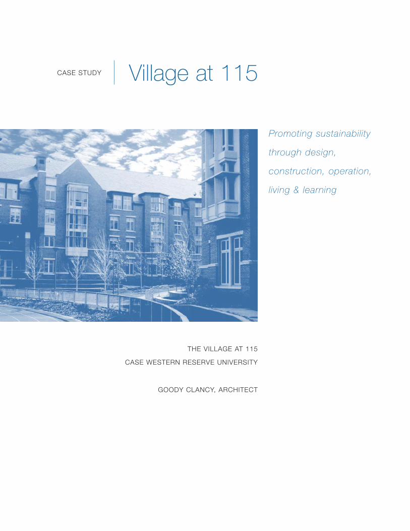
Promoting sustainability
through design,
construction, operation,
living & learning

Contents Overview
Project team
Process
Finance
land use
site
energy
Materials & construction
indoor environment
Ratings
lessons
awards & Recognition
learn More
1
3
4
5
7
8
12
19
21
22
24
25
25
case study Village at 115

C A S E S T U D Y : V I L L A G E AT 1 1 5 | C A S E W E S T E R N R E S E R V E U N I V E R S I T Y | G O O D Y C L A N C Y — A R C H I T E C T S �
Overview
For their new residential village, the stakeholders at Case Western Reserve University
wanted a traditional look that conveyed a sense of history, that featured Case’s strengths in
engineering and innovation, and that met their goals for a more sustainable campus.
At the same time, decisions needed to make fiscal sense, with a reasonable payback.
The “Village at 115” is both traditional and innovative: the residential buildings are
Collegiate Gothic in appearance, but, from the orientation of the buildings to the
selection of brick, the buildings were designed to minimize energy use during both
construction and operation and to promote a sense of community and awareness
of the environment. This attitude of “Living and Learning” guided the design and
construction process, and continues to influence the ongoing operation of the Village.
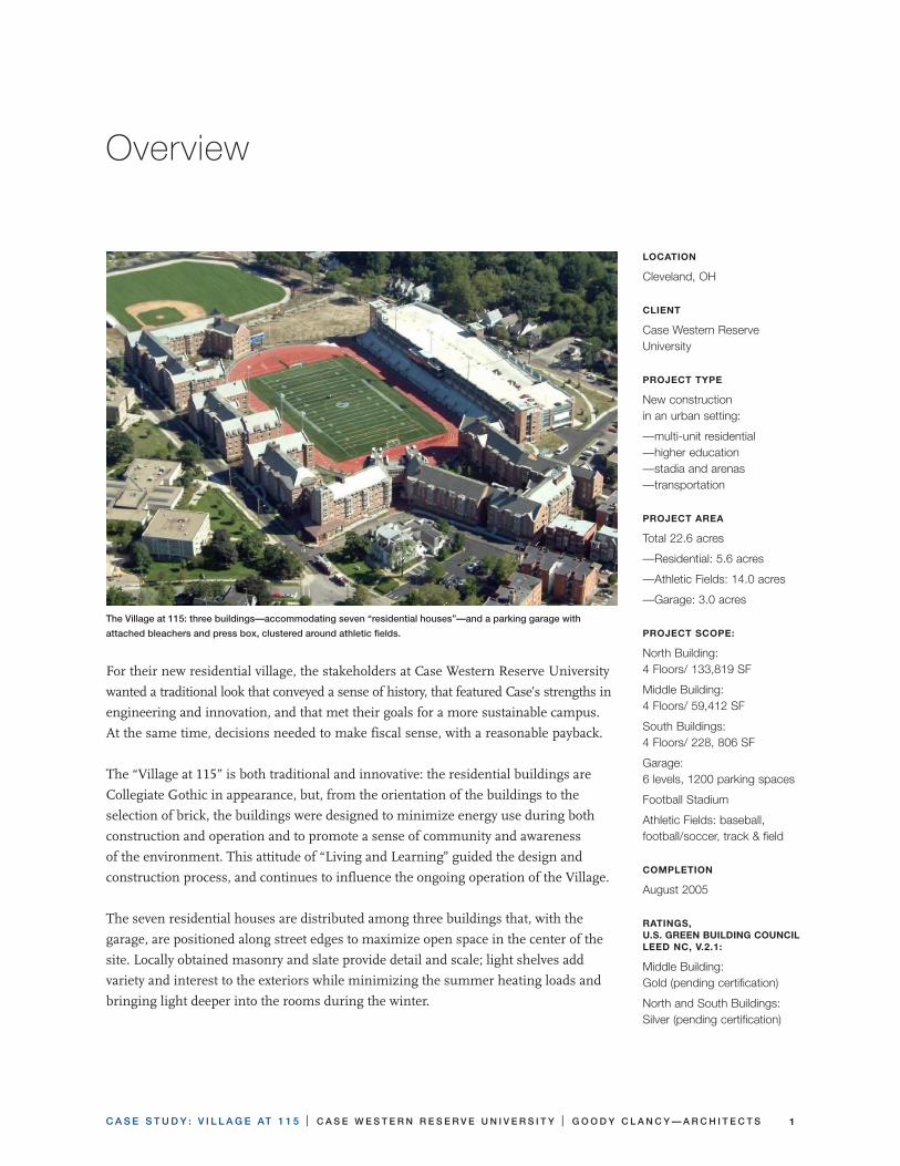
The seven residential houses are distributed among three buildings that, with the
garage, are positioned along street edges to maximize open space in the center of the
site. Locally obtained masonry and slate provide detail and scale; light shelves add
variety and interest to the exteriors while minimizing the summer heating loads and
bringing light deeper into the rooms during the winter.
The Village at 115: three buildings—accommodating seven “residential houses”—and a parking garage with
attached bleachers and press box, clustered around athletic fields.
Location
cleveland, Oh
cLient
case Western Reserve university
PRoJect tyPe
New construction in an urban setting:
—multi-unit residential —higher education —stadia and arenas —transportation
PRoJect aRea
total 22.6 acres
—Residential: 5.6 acres
—athletic Fields: 14.0 acres
—garage: 3.0 acres
PRoJect ScoPe:
North Building: 4 Floors/ 133,819 sF
Middle Building: 4 Floors/ 59,412 sF
south Buildings: 4 Floors/ 228, 806 sF
garage: 6 levels, 1200 parking spaces
Football stadium
athletic Fields: baseball, football/soccer, track & field
comPLetion
august 2005
RatingS, U.S. gReen BUiLding coUnciL Leed nc, v.2.�:
Middle Building: gold (pending certification)
North and south Buildings: silver (pending certification)
C A S E S T U D Y : V I L L A G E AT 1 1 5 | C A S E W E S T E R N R E S E R V E U N I V E R S I T Y | G O O D Y C L A N C Y — A R C H I T E C T S2
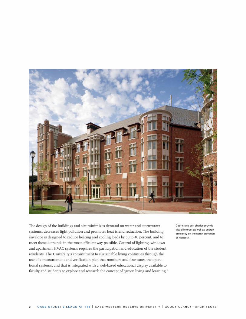
The design of the buildings and site minimizes demand on water and stormwater
systems, decreases light pollution and promotes heat island reduction. The building
envelope is designed to reduce heating and cooling loads by 30 to 40 percent, and to
meet those demands in the most efficient way possible. Control of lighting, windows
and apartment HVAC systems requires the participation and education of the student
residents. The University’s commitment to sustainable living continues through the
use of a measurement and verification plan that monitors and fine tunes the opera-
tional systems, and that is integrated with a web-based educational display available to
faculty and students to explore and research the concept of “green living and learning.”
Cast-stone sun shades provide
visual interest as well as energy
efficiency on the south elevation
of House 3.

C A S E S T U D Y : V I L L A G E AT 1 1 5 | C A S E W E S T E R N R E S E R V E U N I V E R S I T Y | G O O D Y C L A N C Y — A R C H I T E C T S �
Project Team: Village at 115
north Residential Buildings and athletic Fields
Client: Case Western Reserve University
Architect: Goody Clancy & Associates, Inc.
Structural Engineer: Zaldastani Associates, Inc.
Mechanical, Electrical, Plumbing: Bard, Rao + Athanas Consulting Engineers, LLC
Civil Engineer: Neff & Associates, Inc.
Specifications: Falk Associates
Acoustical Consultant: Cavanaugh Tocci Associates, Inc.
Code Consultant: Rolf Jensen Associates, Inc.
Landscape Consultant: Michael Van Valkenburgh Associates
Lighting Consultant: LAM Partners, Inc.
Sports Consultant: HOK
Sports Consultant: Paige Design Group
Sustainable Design: Steven Winter Associates
Sustainable Design: Buro Happold
Commissioning Agent: H.F. Lenz Company
Information Technology Consultants: Karpinski Associates
Contractor: Whiting-Turner Contracting Company
Hydrologist: Hydrosphere Engineering
garage, Press Box and Stadium
Client: Case Western Reserve University
Architect of Record: The HNTB Companies Inc
Design Architect for building exterior: Goody Clancy & Associates
Contractor: Whiting-Turner Contracting Company
C A S E S T U D Y : V I L L A G E AT 1 1 5 | C A S E W E S T E R N R E S E R V E U N I V E R S I T Y | G O O D Y C L A N C Y — A R C H I T E C T S�
Process
At each step of the design process, and through construction and commissioning,
the team—including the owner, construction manager, designers and engineers,
sustainability consultant and the commissioning agent—worked together to challenge
assumptions. As a result of this process, the team considered both new technologies
and more efficient designs of conventional technologies. This was especially evident in
the evolution of the HVAC design.
The first step in evaluating the HVAC systems was to challenge the assumptions for
heating and cooling loads. A detailed energy analysis based on 3D modeling and a
DOE analysis of the building provided a more accurate prediction of loads that took
into consideration the tight building envelope, light shelves, insulation, high-efficiency
windows, and the exact configuration and orientation of the building. This analysis
reduced the design loads by 50 tons of cooling for the three buildings.
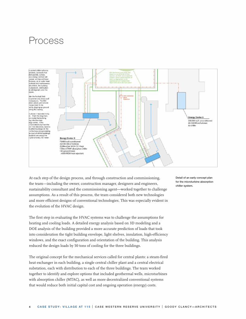
The original concept for the mechanical services called for central plants: a steam-fired
heat exchanger in each building, a single central chiller plant and a central electrical
substation, each with distribution to each of the three buildings. The team worked
together to identify and explore options that included geothermal wells, microturbines
with absorption chiller (MTAC), as well as more decentralized conventional systems
that would reduce both initial capital cost and ongoing operation (energy) costs.
Detail of an early concept plan
for the microturbine absorption
chiller system.
C A S E S T U D Y : V I L L A G E AT 1 1 5 | C A S E W E S T E R N R E S E R V E U N I V E R S I T Y | G O O D Y C L A N C Y — A R C H I T E C T S �
Finance
The project team initiated studies that considered capital cost, the cost of distribution,
present and projected energy cost (cost of gas, steam, electricity), and the intangible
costs of risk—the cost if new technology failed, or the cost of backup systems—as well
as the benefits of publicity and education if new technologies were used.
If the costs were significant without payback, or if the risks were high, the features
were not pursued. In the Cleveland area, the water and electricity costs are low, which
made it difficult to make a case for a reasonable payback for mechanical system
features with additional capital costs. Features that provided cost tradeoffs, such as
improvements to the exterior envelope that increased architectural costs but reduced
HVAC costs, were incorporated.
Most successful were features that were incorporated at no additional cost, such as
the low-flow aerators, chillers with no CFC, HCFCs or Halon, and the groundwater
discharge system.
The final design reduces energy consumption primarily by tailoring the systems to
provide only the amount of energy (heating, cooling, water, or electricity) that is actu-
ally required, and by reducing loss of energy due to waste or inefficient distribution.
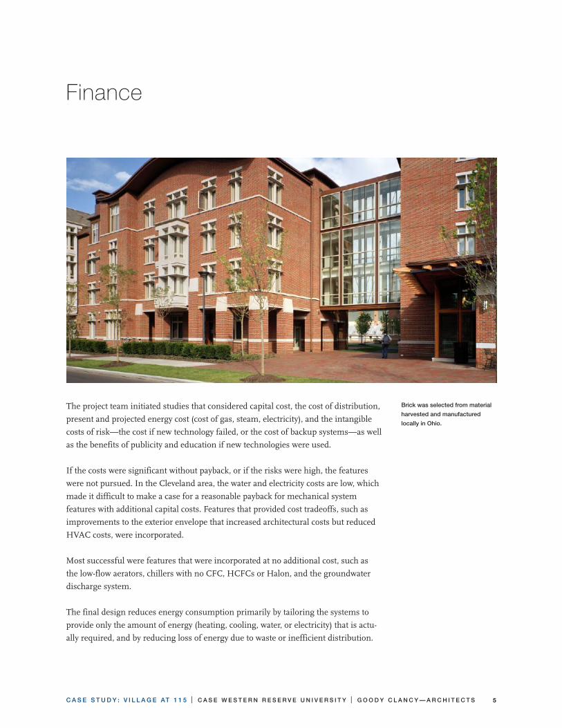
Brick was selected from material
harvested and manufactured
locally in Ohio.

C A S E S T U D Y : V I L L A G E AT 1 1 5 | C A S E W E S T E R N R E S E R V E U N I V E R S I T Y | G O O D Y C L A N C Y — A R C H I T E C T S�
Land Use and Community
Case Western Reserve University is located along the
busy Euclid Avenue commercial corridor on the north-
east side of the city of Cleveland, Ohio. The project site
is one block north of Euclid Avenue between East 115th
and East 118th. To the south, East 116th and East 117th
Streets extended north from Euclid and dead-ended
at the project site. The area to the north of the site is
single-family residential, while the area to the south,
along Euclid, is a mix of residential and business. Little
Italy, a block south of Euclid, is a busy commercial and
restaurant area. The area is served by the Case shuttle
bus, RTA buses, and the Euclid stop of the RTA rapid-
transit commuter train.
The Village at 115 is the residential component of a new
project that includes apartment-style housing for 725
undergraduates, a new parking garage for 1200 cars for
residents and commuters, and replacement of existing
athletic fields.
The project area fell within three existing zoning
districts—residential, multi-family and retail—with
a variety of height and area limits. The project team
worked with the Cleveland Planning Commission to
develop an alternative plan that would balance density
with open space. This new plan extended East 116th
and 117th streets through to the adjacent streets, and
allowed higher-density four-story residential buildings
along the three north-south streets (East 115th, East
116th, and East 117th). All surface parking was replaced
with an eight-story parking structure located on East
118th, the largest of the four north-south streets.
This plan extended the character of the existing brick
apartments located south of the site and provided an
open-space buffer between the project buildings and
the single-family homes to the north. Open space was
Wade PaRk ave
eUcLid a
ve
e ��7th
Ste
���th S
t
e �
��
th
St
e �
�8
th
St
athLeticFieLdS
hoUSe �
FUtUReFieLdhoUSe
gaRage
BLeacheRS/PReSS Box
athLeticFieLdS
hoUSe �
hoUSe 7
hoUSe �
hoUSe �
hoUSe 2
hoUSe �
C A S E S T U D Y : V I L L A G E AT 1 1 5 | C A S E W E S T E R N R E S E R V E U N I V E R S I T Y | G O O D Y C L A N C Y — A R C H I T E C T S 7
maximized by locating the soccer/football field in the center of the site, providing
optimum views from the buildings and individual courtyards. As a bonus, the majority
of the buildings were oriented on a north-south axis, minimizing heating loads from
south-facing elevations.
Strategies for Sustainable Land Use
• PropertyEvaluation
— Assess property for integration into local and regional transportation corridors
— Investigate property for possible contaminants (e.g., toxic/hazardous wastes, dumps)
• SupportforAppropriateTransportation
— Design development to have pedestrian emphasis rather than auto emphasis
—Provide storage area for bicycles
—Provide access to public transportation
—Provide vehicle access to support car- and vanpooling
• ResponsiblePlanning
— Ensure that development fits within a responsible local and regional planning
framework
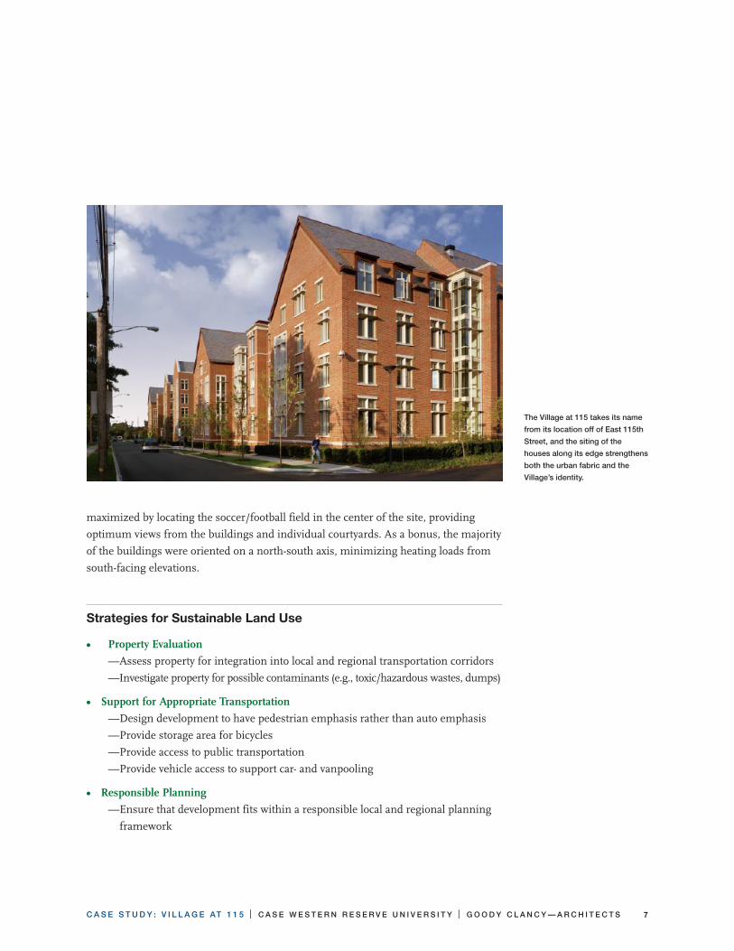
The Village at 115 takes its name
from its location off of East 115th
Street, and the siting of the
houses along its edge strengthens
both the urban fabric and the
Village’s identity.

C A S E S T U D Y : V I L L A G E AT 1 1 5 | C A S E W E S T E R N R E S E R V E U N I V E R S I T Y | G O O D Y C L A N C Y — A R C H I T E C T S8
Site
The site was originally covered by athletic fields and surface parking lots. In the new
Village, all parking has been consolidated in the parking garage and the athletic fields
have been relocated to the center of the site. The remaining open space has been
restored with rolling lawns, ground cover and perennial trees and shrubs, with an
emphasis on native and drought-resistant planting.
The open areas are loosely divided into the public street side, and the more private
“courtyard side.” The three residential buildings are divided into seven “houses,” each
with its own public entrance, private back door, and courtyard. The courtyards overlook
the football/soccer field, and to the north is the baseball field, visible through the
open end of the football/soccer field. Each area provides opportunities for sustainable
design at a variety of scales.
The lighting on the site features a combination of traditional fixtures along the street
and a more contemporary style in the courtyards. Both minimize light pollution, and
the traditional model was carefully selected to provide a shielded fixture similar in
appearance to the campus-standard acorn, which does not have shielding.
In the courtyard of the middle building, Case is experimenting with the use of
drought-resistant “buffalo” grass, which will not need to be irrigated after it is estab-
The residential buildings of the
Village at 115 are clustered
around the football/soccer field.

C A S E S T U D Y : V I L L A G E AT 1 1 5 | C A S E W E S T E R N R E S E R V E U N I V E R S I T Y | G O O D Y C L A N C Y — A R C H I T E C T S �
lished. Initially, there was concern that native grass would look unkempt, or resemble
a wheat field, but the specified grass looks like a conventional lawn. If successful, the
“buffalo” grass could be used on future projects.
The large open areas provided by the football/soccer field and the baseball field present-
ed different opportunities for additional uses. Early in the schematic design, the design
team investigated the use of geothermal wells for heating and cooling, but determined
that they were not feasible for this project. Shallow geothermal wells (300 feet) have
been used successfully at Trinity Cathedral in Cleveland and at the Environmental
Center at nearby Oberlin College, but the heating and cooling demands of the Village
would require wells over the entire open space of the fields, and this proved too
expensive. Deep wells (1500 feet), such as those used successfully by Goody Clancy at
Trinity Church in Boston, were also investigated, and looked financially feasible until it
was discovered that the Cleveland area is known for gas pockets. As a result, deep wells
were too risky because the only way to confirm the location of the pockets was to drill.
On the other hand, Cleveland’s unique geology was perfect for a groundwater-recharge
system. The local beach and glacial lake bottom deposits from the Wisconsin Glacial
Period are now used to collect 70% of the stormwater from both buildings and site,
including the garage and football field, and divert it into perforated pipes under the ath-
letic fields, where it can percolate directly through this substrate into the groundwater.
Strategies for a Sustainable Site
• DevelopmentImpact
—Minimize building footprint
—Limit parking area
—Manage storm water on site
• LandscapePlantings
—Landscape with indigenous vegetation
• Low-Water-UseFixtures
—Use low-flow toilets
• DemandforIrrigation
—Select plants for drought tolerance
• SitePlanning
—Provide for solar access
C A S E S T U D Y : V I L L A G E AT 1 1 5 | C A S E W E S T E R N R E S E R V E U N I V E R S I T Y | G O O D Y C L A N C Y — A R C H I T E C T S�0
groundwater Recharge
The entire project area is situated over a shallow unconfined sand aquifer—25 feet
of brown and gray sand—over shale. The design team worked with the civil and
geotechnical engineers to perform physical tests on-site to determine the water levels
and percolation rate, and worked with a hydrologist who created computer models
to determine the likely performance of a system. Analysis included both theoretical
and on-site percolation tests to ensure that the system would absorb water from a
100-year storm and that the ongoing process would not affect the substrate of the
athletic fields above.
In order to slow the rate of heated stormwater runoff from building roofs, a system
of gravel strips was specified and installed around the perimeter of the buildings. The
gravel strips are troughs comprised of washed river stone confined by an impermeable
membrane with a perforated pipe at their bottom to collect the runoff. In areas where
gravel strips could not be utilized, such as building entrances, roof runoff is collected
by gutters and downspouts in a traditional method. The collective runoff from the
downspouts and gravel strips is directed to catch basins equipped with sumps and
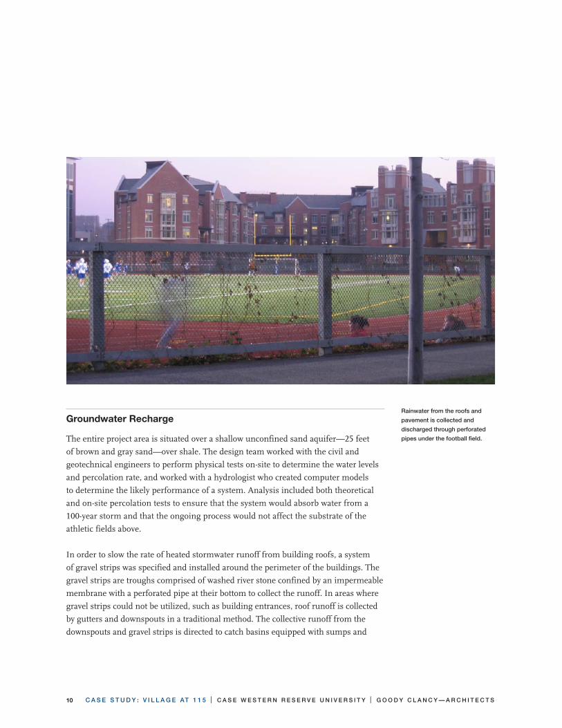
Rainwater from the roofs and
pavement is collected and
discharged through perforated
pipes under the football field.
C A S E S T U D Y : V I L L A G E AT 1 1 5 | C A S E W E S T E R N R E S E R V E U N I V E R S I T Y | G O O D Y C L A N C Y — A R C H I T E C T S ��
traps. These catch basins allow sediment and debris to settle out of the stormwater
where it can be removed from the system during periodic maintenance. The storm-
water then travels in solid pipes to a system of manholes and perforated pipes located
under the football field. The perforated pipes allow the stormwater to percolate into the
sand aquifer over a large area.
The perimeter manholes are designed with a high-overflow system that will divert
excess water to a similar distribution system under the baseball field. At the end of
the system is an overflow structure that connects to the municipal combined sewer
system. Computer simulations and field tests indicate that the system and underlying
sand have sufficient capacity to absorb all of the water that is diverted to the system.
This is especially important because of the existence of combined sewers (off site) that
carry both stormwater and sanitary sewage flows. Eliminating seventy percent of the
stormwater runoff from this site will decrease the burden on the existing wastewater-
treatment plant during storm events.
Approximately thirty percent of the stormwater runoff from the site could not be
diverted and is transported directly to the municipal sewer system. This runoff is
primarily from roofs located in areas along the street that could not be connected to
the recharge system via gravity sewers.
The recharge system also collects all stormwater runoff from the adjacent parking ga-
rage, and from all storm drains in the courtyards. The new synthetic football field has
its own drainage system that will divert stormwater to the recharge system, although
most water on the field is expected to bypass the collection system and percolate
directly into the sand layer below.
C A S E S T U D Y : V I L L A G E AT 1 1 5 | C A S E W E S T E R N R E S E R V E U N I V E R S I T Y | G O O D Y C L A N C Y — A R C H I T E C T S�2
Energy
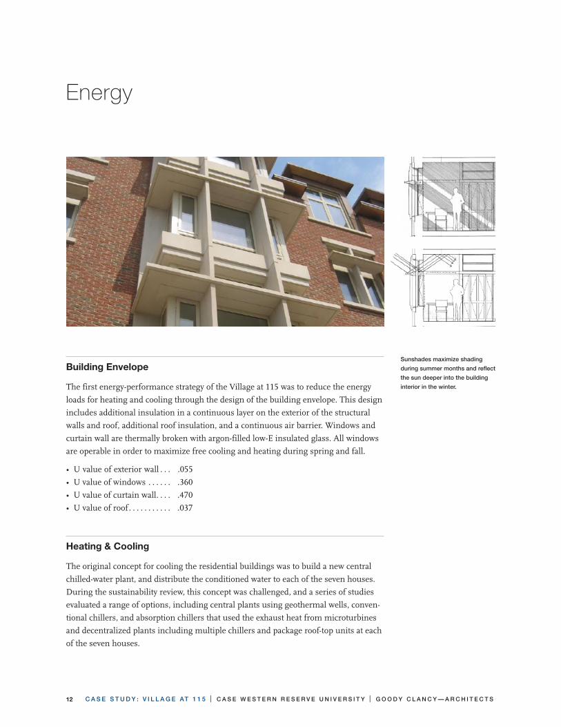
Building envelope
The first energy-performance strategy of the Village at 115 was to reduce the energy
loads for heating and cooling through the design of the building envelope. This design
includes additional insulation in a continuous layer on the exterior of the structural
walls and roof, additional roof insulation, and a continuous air barrier. Windows and
curtain wall are thermally broken with argon-filled low-E insulated glass. All windows
are operable in order to maximize free cooling and heating during spring and fall.
• U value of exterior wall . . . .055
• U value of windows . . . . . . .360
• U value of curtain wall . . . . .470
• U value of roof . . . . . . . . . . . .037
heating & cooling
The original concept for cooling the residential buildings was to build a new central
chilled-water plant, and distribute the conditioned water to each of the seven houses.
During the sustainability review, this concept was challenged, and a series of studies
evaluated a range of options, including central plants using geothermal wells, conven-
tional chillers, and absorption chillers that used the exhaust heat from microturbines
and decentralized plants including multiple chillers and package roof-top units at each
of the seven houses.
Sunshades maximize shading
during summer months and reflect
the sun deeper into the building
interior in the winter.

C A S E S T U D Y : V I L L A G E AT 1 1 5 | C A S E W E S T E R N R E S E R V E U N I V E R S I T Y | G O O D Y C L A N C Y — A R C H I T E C T S ��
The initial plan for heating was to distribute steam to each house from the university-
affiliated MCCO steam system, which generates steam off-site from coal and gas.
Alternative studies included the use of geothermal wells, the use of microturbines to
heat the buildings, and alternatives for distributing the steam, including converting the
steam to hot water in a central location, and distributing the hot water to each house.
Studies of the distribution costs and losses determined a decentralized system was
most efficient: large enough to use standard equipment sizes, but small enough to
minimize distribution costs. In the final design, hot and chilled water are generated
at two central locations. One plant serves the four houses in the south building, and
another serves the three houses in the middle and north building. A two-pipe change-
over system controlled by outside air temperature is used for both site and building
distribution. The system is designed to reduce energy use and loss, and maximize use
of free cooling and heating during the “shoulder” seasons of spring and fall.
The team studied options for distribution of conditioned air within the building,
including an all-air-ducted system and an all-water/vertical-fan-coil system. These
studies considered capital and operational cost, but also considered the impact by,
and on, the users. It was determined that a single fan-coil system for each apartment,
with ducted air distribution within the apartment, would provide the best balance of
occupant versus building control. Occupants can control the supply of conditioned
air in their apartment through use of the thermostat, and to their individual rooms by
way of a mechanical damper. However, because the temperature of conditioned water
serving the fan coils is controlled by outside air temperature, the overall system is less
susceptible to abuse. An example is a student going away for the weekend and leaving
a window open: An unexpected drop in temperature will cause the local unit to run in
response, but the building and site distribution will be unaffected.
ventilation
Energy use was also reduced in the ventilation system. Typically, the minimum rate of
air flow for the ventilation system is dictated by the lowest rate that can be measured
while balancing the system even though the minimum required by codes for ventila-
tion is much lower. This discrepancy was discovered during the DOE energy analysis
by the sustainability consultant. During a brain-storming session with the engineers,
sustainability consultant, commissioning agent, and Case’s Facilities Department
(which would maintain and operate the system), a system was designed that would
provide the higher flows required for testing and balancing, and then use variable-

C A S E S T U D Y : V I L L A G E AT 1 1 5 | C A S E W E S T E R N R E S E R V E U N I V E R S I T Y | G O O D Y C L A N C Y — A R C H I T E C T S��
speed drives to reduce the overall airflow to meet code ventilation minimums for the
life of the building. This design saves energy by eliminating the need to temper the
additional volume of air.
In addition, an energy recovery unit at each house will transfer latent and sensible heat
from exhaust air systems to preheat the outside ventilation air.
measurement & verification
A “Measurement & Verification” plan is in place to allow the Facilities Department,
faculty researchers and students to analyze the usage of water, electricity, natural gas,
and steam and to compare the consumption between buildings within the Village at
115 and other residential buildings on the Case campus. The measurement-and-veri-
fication plan will provide comparisons on a monthly and/or yearly basis. This data, as
well as additional, continuously compiled data, will be available through an internet-
based educational display, and in greater detail on a case-by-case basis for educational
and research projects by the Facility Department, students and/or faculty.
The system is tied to a weather station on campus that measures and reports wind speed,
temperature, and humidity so that energy use can be directly related to weather conditions.
The flow of information from
the Village’s “Measurement &
Verification” system begins at
meters at each house and at the
campus weather station (left side
of diagram) and is compiled and
distributed through the internet to
Case websites and house kiosks
(right side of diagram).
C A S E S T U D Y : V I L L A G E AT 1 1 5 | C A S E W E S T E R N R E S E R V E U N I V E R S I T Y | G O O D Y C L A N C Y — A R C H I T E C T S ��
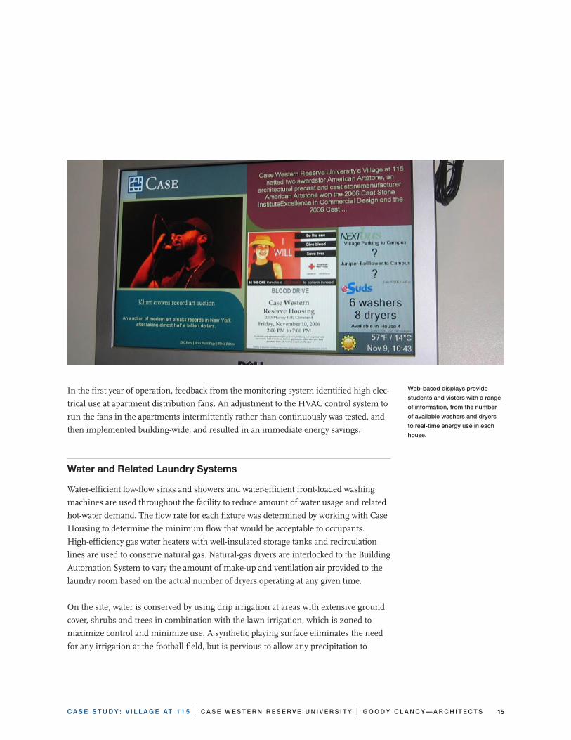
In the first year of operation, feedback from the monitoring system identified high elec-
trical use at apartment distribution fans. An adjustment to the HVAC control system to
run the fans in the apartments intermittently rather than continuously was tested, and
then implemented building-wide, and resulted in an immediate energy savings.
Water and Related Laundry Systems
Water-efficient low-flow sinks and showers and water-efficient front-loaded washing
machines are used throughout the facility to reduce amount of water usage and related
hot-water demand. The flow rate for each fixture was determined by working with Case
Housing to determine the minimum flow that would be acceptable to occupants.
High-efficiency gas water heaters with well-insulated storage tanks and recirculation
lines are used to conserve natural gas. Natural-gas dryers are interlocked to the Building
Automation System to vary the amount of make-up and ventilation air provided to the
laundry room based on the actual number of dryers operating at any given time.
On the site, water is conserved by using drip irrigation at areas with extensive ground
cover, shrubs and trees in combination with the lawn irrigation, which is zoned to
maximize control and minimize use. A synthetic playing surface eliminates the need
for any irrigation at the football field, but is pervious to allow any precipitation to
Web-based displays provide
students and vistors with a range
of information, from the number
of available washers and dryers
to real-time energy use in each
house.

C A S E S T U D Y : V I L L A G E AT 1 1 5 | C A S E W E S T E R N R E S E R V E U N I V E R S I T Y | G O O D Y C L A N C Y — A R C H I T E C T S��
percolate through the system into the sand. Drought-resistant “buffalo” grass is used
in the House 5 courtyard as a test in anticipation of more extensive use during future
phases. Seventy percent of the stormwater, including roof runoff and site drainage, is
collected on site and distributed through perforated pipes in the existing sand sub-
strate, where it percolates into the groundwater table rather than being drained into
municipal storm systems.
Power and Lighting design
The Village public and private (apartment) spaces are designed to maximize light and
views. Each house has a living room that opens onto an exterior courtyard. Interior
corridors extend to the exterior wall in order to provide views and daylight to interior
corridors. Energy use for lighting is also reduced through the use of natural lighting
provided by large windows, with light shelves on south and east elevations. Remaining
lighting loads are reduced through control and use of energy-efficient fixtures, most of
which are fluorescent.
Local motion sensors are used to control all lights (except emergency lights) in
bathrooms, exit and house stairs, and corridors. In egress paths, alternate fixtures, or
alternate lamps within the fixture, are wired on separate circuits so that emergency
lighting systems can operate independently of the motion controlled system.
The control system takes
advantage of large windows by
dimming the artificial lighting
when natural light meets the
desired light load.

C A S E S T U D Y : V I L L A G E AT 1 1 5 | C A S E W E S T E R N R E S E R V E U N I V E R S I T Y | G O O D Y C L A N C Y — A R C H I T E C T S �7
In the house living room, the lighting-control system allows occupants to set the light-
ing level in the house living room to a variety of settings. Daylight sensors read the
amount of natural daylight, and automatically adjust the light levels of fixtures, based
on the current setting at the light-control system.
Electrical distribution is designed to reduce power loss due to lower voltage distribu-
tion by using decentralized distribution panels wherever possible. Each house is
fed from high-voltage switchgear within the basement of the house. Substations are
located in Houses 2, 3, 4, 5, and 6. Houses 1 and 2 share a substation, and Houses 6
and 7 share a substation. The substation in House 3, which has a back-up emergency
generator, also feeds all systems in all houses that would require emergency power
or standby power. Within each house, power is distributed directly to a power and
lighting panel within the suite.
Strategies for Reduced Power consumption
• CoolingSystems
—Commission the HVAC system
• DaylightingforEnergyEfficiency
—Use building elements to redirect daylight and control glare
—Daylight sensors tied to lighting control dimmer system
• LightingControls
—Use occupancy sensors
• HotWaterLoads
—Use water-efficient faucets
• HVACDistributionSystems
—Size fans and pumps properly to meet the loads
• HVACControlsandZoning
—Provide sufficient sensors and control logic
—Use direct digital control (DDC) system

C A S E S T U D Y : V I L L A G E AT 1 1 5 | C A S E W E S T E R N R E S E R V E U N I V E R S I T Y | G O O D Y C L A N C Y — A R C H I T E C T S�8
microturbine absorption chiller cogeneration System
Investigation of the MTAC (Microturbine absorption chiller cogeneration) system
continued through the design and document phase, and was eventually bid as an alter-
nate for one of the houses. This technology uses gas-fired turbine engines to generate
electricity and exhaust heat. The heat is captured for heating during the winter, and
fires an absorption chiller during the summer.
Although the system looked promising, it proved to be not practical on this project
for a number of reasons. First, Case was uncomfortable with the potential risk of
using new technology to heat residential buildings, and wanted a complete backup
heating system. Second, because the University paid very competitive rates for steam,
but relatively higher rates for gas, the best scenario was a payback period of 50 years,
longer than the life of the equipment. The worst-case scenario was that Case would pay
a premium—the system would cost more to operate than the conventional system.
Determining the payback proved to be a complicated and hypothetical process. The
MTAC would require supplemental steam during the summer for the absorption
chillers, and would generate some, but not all, electricity required by the buildings.
The payback period would be affected by future cost of steam, gas and electricity.
The cost of energy on a project this size had tremendous impact, and the difference
between five cents and ten cents for gas or electricity made the difference between
breaking even and a loss. The steam generated near campus was fired by coal, but the
future changeover to gas would make it both cleaner and more expensive.
Because the university valued the research, publicity and educational benefits, they
chose to bid the MTAC system as an alternate, and investigate potential grants and
other supplemental funding. The final blow was that the cost was substantially higher
than estimated, in part because the subcontractors were unfamiliar with the system
and with the potential costs.
Although the system was not used, all parties became more familiar with a system that
had the potential to be economical under different circumstances. The same system
has been used with great success at the YMCA in Angola, Indiana, where the swim-
ming pool provides more constant use of the heat, funding and grants were available,
the local utility rates were more favorable, and the local electrical company bought
back excess electricity.
C A S E S T U D Y : V I L L A G E AT 1 1 5 | C A S E W E S T E R N R E S E R V E U N I V E R S I T Y | G O O D Y C L A N C Y — A R C H I T E C T S ��
Materials and Construction
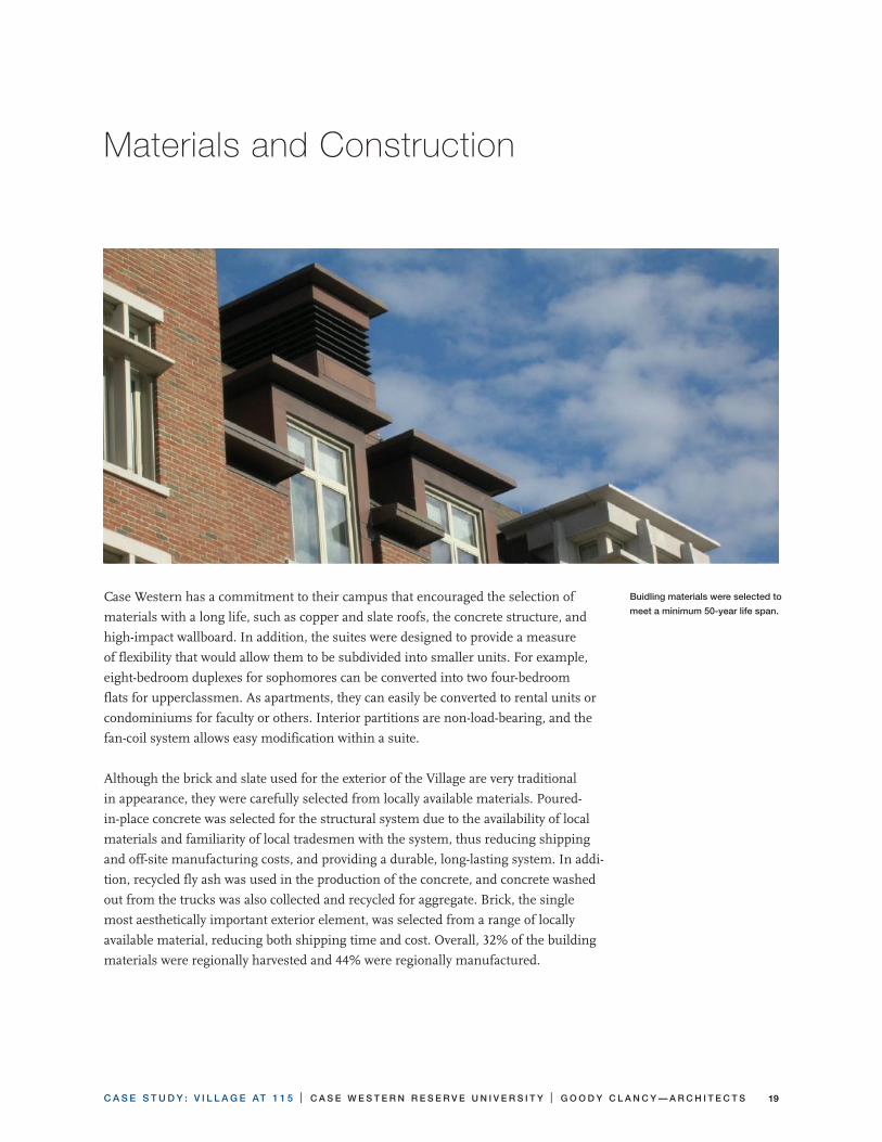
Case Western has a commitment to their campus that encouraged the selection of
materials with a long life, such as copper and slate roofs, the concrete structure, and
high-impact wallboard. In addition, the suites were designed to provide a measure
of flexibility that would allow them to be subdivided into smaller units. For example,
eight-bedroom duplexes for sophomores can be converted into two four-bedroom
flats for upperclassmen. As apartments, they can easily be converted to rental units or
condominiums for faculty or others. Interior partitions are non-load-bearing, and the
fan-coil system allows easy modification within a suite.
Although the brick and slate used for the exterior of the Village are very traditional
in appearance, they were carefully selected from locally available materials. Poured-
in-place concrete was selected for the structural system due to the availability of local
materials and familiarity of local tradesmen with the system, thus reducing shipping
and off-site manufacturing costs, and providing a durable, long-lasting system. In addi-
tion, recycled fly ash was used in the production of the concrete, and concrete washed
out from the trucks was also collected and recycled for aggregate. Brick, the single
most aesthetically important exterior element, was selected from a range of locally
available material, reducing both shipping time and cost. Overall, 32% of the building
materials were regionally harvested and 44% were regionally manufactured.
Buidling materials were selected to
meet a minimum 50-year life span.
C A S E S T U D Y : V I L L A G E AT 1 1 5 | C A S E W E S T E R N R E S E R V E U N I V E R S I T Y | G O O D Y C L A N C Y — A R C H I T E C T S20
The interiors are residential in character, with extensive use of wood paneling and
trim, and a variety of carpet patterns and paint colors. From the ceiling tiles to the
carpet, selections were made to maximize recycled content—10% overall—and
minimize volatile organic compounds (VOC). Of these, the greatest challenge was to
find a carpet that had recycled content, was durable and also offered a variety of colors
and patterns. The final selection resulted in two manufacturers with carpeting that
both had recycled content (24–25%) and was locally manufactured (within a 500-mile
radius from the construction site).
Strategies for Sustainable construction
• JobSiteRecycling
—Require a waste-management plan from the contractor
—Investigate local infrastructure for recycling
• RecyclingbyOccupants
—Specify recycling receptacles that are accessible to the occupants
—Design a physical in-house recycling system
• ToxicUpstreamorDownstreamBurdens
—Use true linoleum flooring
• Pre-ConsumerRecycledMaterials
—Use recycled materials as aggregate in the concrete
—Specify carpet made with recycled-content face fiber
—Use recycled-content rubber flooring
• GreenhouseGasEmissionsfromManufacture
—Use concrete with fly ash replacing a portion of the cement
• TransportationofMaterials
—Prefer materials that are sourced and manufactured within the local area

C A S E S T U D Y : V I L L A G E AT 1 1 5 | C A S E W E S T E R N R E S E R V E U N I V E R S I T Y | G O O D Y C L A N C Y — A R C H I T E C T S 2�
Indoor Environment
The interiors are designed to be warm and welcoming, and to encourage social and
intellectual interaction. Behind the scenes, the buildings are designed to provide a
healthy environment. Paints, adhesives, and wood composites were all selected to meet
low-VOC criteria, and selections were monitored during submittal process and con-
struction to ensure that the criteria were met. The buildings were monitored during
construction to minimize the introduction of dirt and dust into mechanical systems,
and the buildings’ ventilation systems were flushed prior to occupancy.
Strategies for a healthy environment
• EntryofPollutants
—Design entry to facilitate removal of dirt before entering building
• VentilationandFiltrationSystems
—Provide occupants with access to operable windows
• ThermalComfort
—Use glazing with a low solar-heat-gain coefficient
—Provide occupants with the means to control temperature in their area
• VisualComfortandLightSources
—Use electronic ballasts with fluorescent lighting
—Provide occupants with control of light in their area
—Provide illumination sensor
• ReductionofIndoorPollutants
—Use only very low- or no-VOC paints
All materials met criteria for
low content of volatile organic
compounds.
C A S E S T U D Y : V I L L A G E AT 1 1 5 | C A S E W E S T E R N R E S E R V E U N I V E R S I T Y | G O O D Y C L A N C Y — A R C H I T E C T S22
Ratings
The Village at 115 as a whole was designed with a goal of obtaining a LEED Silver
rating. The middle building, which has additional features—such as drought-resistant
landscaping and lighting controls for measurement and verification—that may allow
it to reach a higher rating, was submitted in 2007 for certification with the U.S. Green
Building Council LEED-NC, v.2.1, with a goal of Gold (41 points), as rated below:
• SustainableSites,8of14possiblepoints
—SS Prerequisite 1, Erosion & Sedimentation Control
—SS Credit 1, Site Selection
—SS Credit 2, Urban Redevelopment
—SS Credit 4.1, Alternative Transportation, Public Transportation Access
—SS Credit 4.2, Alternative Transportation, Bicycle Storage & Changing Rooms
—SS Credit 5.1, Reduced Site Disturbance, Protect or Restore Open Space
—SS Credit 6.1, Stormwater Management, Rate and Quantity
—SS Credit 7.1, Landscape & Exterior Design to Reduce Heat Islands, Non-Roof
—SS Credit 7.2, Landscape & Exterior Design to Reduce Heat Islands, Roof
• WaterEfficiency,3of5possiblepoints
—WE Credit 1.1, Water Efficient Landscaping, Reduce by 50%
—WE Credit 3.1, Water Use Reduction, 20% Reduction
—WE Credit 3.2, Water Use Reduction, 30% Reduction
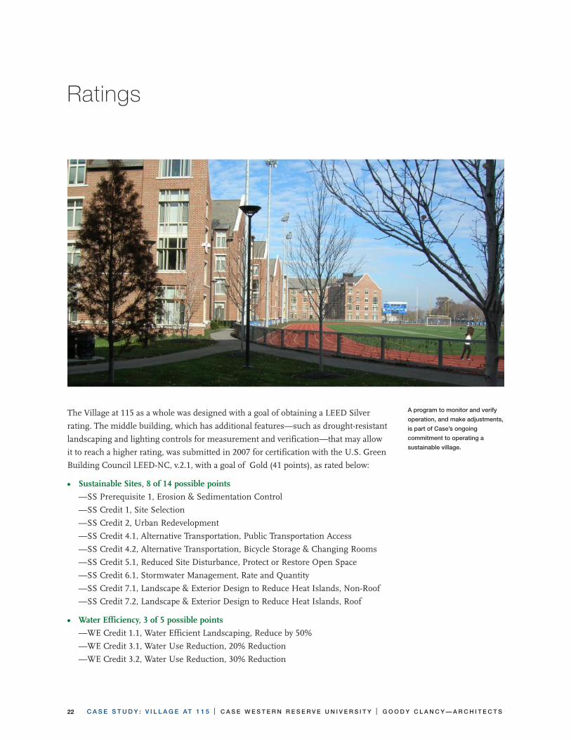
A program to monitor and verify
operation, and make adjustments,
is part of Case’s ongoing
commitment to operating a
sustainable village.

C A S E S T U D Y : V I L L A G E AT 1 1 5 | C A S E W E S T E R N R E S E R V E U N I V E R S I T Y | G O O D Y C L A N C Y — A R C H I T E C T S 2�
• EnergyandAtmosphere,9of17possiblepoints
—EA Prerequisite 1, Fundamental Building Systems Commissioning
—EA Prerequisite 2, Minimum Energy Performance
—EA Prerequisite 3, CFC Reduction in HVAC&R Equipment
—EA Credit 1.1-1.10, Optimize Energy Performance
—EA Credit 3, Additional Commissioning
—EA Credit 4, Ozone Depletion
—EA Credit 5, Measurement and Verification
• MaterialsandResources,5of13possiblepoints
—MR Prerequisite 1, Storage & Collection of Recyclables
—MR Credit 2.1, Construction Waste Management, Divert 50%
—MR Credit 4.1, Recycled Content: 5% (post-consumer + 1/2 post-industrial)
—MR Credit 4.2, Recycled Content: 10% (post-consumer + 1/2 post-industrial)
—MR Credit 5.1, Local/Regional Materials, 20% Manufactured Locally
—MR Credit 5.2, Local/Regional Materials, of 20% Above, Harvested Locally
• IndoorEnvironmentalQuality,11of15possiblepoints
—EQ Prerequisite 1, Minimum IAQ Performance
—EQ Prerequisite 2, Environmental Tobacco Smoke (ETS) Control
—EQ Credit 3.1, Construction IAQ Management Plan, During Construction
—EQ Credit 3.2, Construction IAQ Management Plan, Before Occupancy
—EQ Credit 4.1, Low-Emitting Materials, Adhesives & Sealant
—EQ Credit 4.2, Low-Emitting Materials, Paints
—EQ Credit 4.3, Low-Emitting Materials, Carpet
—EQ Credit 4.4, Low-Emitting Materials, Composite Wood
—EQ Credit 5, Indoor Chemical & Pollutant Source Control
—EQ Credit 6.1, Controllability of Systems, Perimeter
—EQ Credit 7.1, Thermal Comfort, Comply with ASHRAE 55-1992
—EQ Credit 8.1, Daylight & Views, Daylight 75% of Spaces
—EQ Credit 8.2, Daylight & Views, Views for 90% of Spaces
• InnovationandDesignProcess,5of5possiblepoints
—ID Credit 1.1, Innovation in Design “Integrated Pest Management”
—D Credit 1.2, Innovation in Design “Ground Water Recharge”
—ID Credit 1.3, Innovation in Design “Educational Display”
—ID Credit 1.4, Innovation in Design “Exemplary Performance in Recycled Content and Local Materials”
—ID Credit 2, LEED® Accredited Professional
C A S E S T U D Y : V I L L A G E AT 1 1 5 | C A S E W E S T E R N R E S E R V E U N I V E R S I T Y | G O O D Y C L A N C Y — A R C H I T E C T S2�
Lessons
The design of the Village at 115 benefited from the commitment of all team members
early in the design and construction process. Although many of the more exciting early
concepts, such as the microturbine absorption chiller cogeneration system, ultimately
did not prove feasible, the very process of exploring and designing the system expand-
ed everyone’s understanding of both conventional and new systems, and the impact
of design on energy consumption, and resulted in a better project. Buro Haphold and
Steven Winter Associates worked with Bard Rao and Athanas to develop options for
mechanical systems, and then to fine-tune those systems to provide the optimum
performance. H.F. Lenz Company provided comment and critique during design, and
challenging commentary during construction that ensured that the final product met
the intent of the designers. During all phases, the Owner and Construction Manager
were committed to and contributed to the exploration of sustainable ideas, ranging
from consideration of fuel cells (by Owner) to recycling concrete waste (by CM). This
teamwork, which encouraged contributions from different perspectives, was critical to
the success of the project. One lesson learned: It is never too early for participants to
get involved.
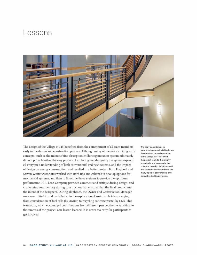
The early commitment to
incorporating sustainability during
the construction and operation
of the Village at 115 allowed
the project team to throroughly
investigate and appreciate the
potential benefits, limitations and
and tradeoffs associated with the
many types of conventional and
innovative building systems.

C A S E S T U D Y : V I L L A G E AT 1 1 5 | C A S E W E S T E R N R E S E R V E U N I V E R S I T Y | G O O D Y C L A N C Y — A R C H I T E C T S 2�
Awards & Recognition
The Village at 115 has been recognized with an Honor Award for Excellence in
Campus Planning, bestowed jointly by the Society for College and University
Planning and the American Institute of Architects Committee on Architecture for
Education. In addition the project won a 2007 Golden Trowel Award for Brick from
the Ohio Chapter of the International Masonry Institute.
Learn More
For more information on real-time energy use at the Village at 115, click on “Village at
115 Real Power Graph” at http://www.case.edu/finadmin/plantsrv/
For more information on the Village at 115, contact:
Don Kamalsky
Associate Vice President of Student Affairs
Case Western Reserve University
10900 Euclid Avenue
Cleveland, Ohio 44106
216.368.3780
www.housing.case.edu
Susan Pranger
Goody Clancy
420 Boylston Street
Boston, MA 02116
617.262.2760 (main)
617.262.9512 (fax)
www.goodyclancy.com

C A S E S T U D Y : V I L L A G E AT 1 1 5 | C A S E W E S T E R N R E S E R V E U N I V E R S I T Y | G O O D Y C L A N C Y — A R C H I T E C T S2�

C A S E S T U D Y : V I L L A G E AT 1 1 5 | C A S E W E S T E R N R E S E R V E U N I V E R S I T Y | G O O D Y C L A N C Y — A R C H I T E C T S 27


