ECOTEL® VoIP ECOTEL® ISDN2-1 ECOTEL® ISDN2-2
A device for providing network interconnectivity between VoIP, ISDN and GSM or between ISDN and GSM
User manual
Edition 3.2-EN
VIERLING Communications GmbH
70469.202/20 – 3.2-EN – 20060530
VIERLING Communications GmbH
Pretzfelder Straße 21, D-91320 Ebermannstadt
Postfach 11 65, D-91316 Ebermannstadt
E-Mail: [email protected]
Internet: http://www.vierling.de/
© 2006 VIERLING Communications GmbH, Ebermannstadt
All rights reserved. Any reproduction, further processing or dissemination of this document or its contents, whether in whole or in part, by any means is expressly prohibited without the prior written consent of VIERLING Communications GmbH.
We reserve the right to make changes without prior notice. Please note that great care was exercised in the preparation of this text. However, VIERLING Communications GmbH does not accept any liability for any errors that might be present in the text.
VIERLING
ECOTEL® VoIP/ISDN2-1/ISDN2-2 Edition 3.2-EN – 20060530 Page 3
Content
1 Introduction ...................................................................... 9
1.1 Overview: Please read this first! ....................................... 10 1.2 Safety instructions ............................................................ 11
2 Getting started................................................................ 14
2.1 Overview: Getting ECOTEL up and running..................... 15 2.2 Installation guideline......................................................... 16
2.2.1 Determining the connection type.......................... 16 2.2.2 Preparing for installation ...................................... 17 2.2.3 Connecting the device ......................................... 18 2.2.4 Setting up the USB interface................................ 19 2.2.5 Installing the configuration software..................... 21 2.2.6 Configuration steps in Service Gear..................... 22 2.2.7 Configuration steps in Gateway Configuration ..... 24 2.2.8 Configuration steps in Basic Configuration .......... 26 2.2.9 Configuration steps in User Registration.............. 28 2.2.10 Configuration steps in Routing Table ................... 29 2.2.11 Configuration steps in SIM Management ............. 30 2.2.12 Configuration steps in Firmware Tools................. 32 2.2.13 Checking for proper operation.............................. 33 2.2.14 Finishing the installation procedure...................... 34
2.3 Getting further information................................................ 34
3 Operating modes............................................................ 35
3.1 Overview: Using ECOTEL ................................................ 36 3.2 ISDN interface: Selecting the ISDN connection type ........ 38
3.2.1 Connection to the internal S0 port/PTMP............. 39 3.2.2 Connection to the internal S0 port/PTP................ 41 3.2.3 Connection to the external S0 port/PTMP............ 43 3.2.4 Connecting ISDN telephones............................... 45 3.2.5 Connection to an external S0 port/PTP................ 47
VIERLING
Page 4 Edition 3.2-EN – 20060530 ECOTEL® VoIP/ISDN2-1/ISDN2-2
3.2.6 Connection as a LCR in PTP mode ..................... 49 3.2.7 Connection to an external S0 port/PTP
(external synchronization) .................................... 51 3.2.8 Connection to an external S0 port/PTP
(internal synchronization) ..................................... 53 3.3 VoIP interface: Sample applications ................................. 55
3.3.1 Media gateway for calls from the ISDN PBX to VoIP and to GSM mobile radio networks ............. 55
3.3.2 Call routing via the VoIP port of the PBX ............. 58 3.3.3 Call routing via a SIP server (soft PBX) in the
LAN...................................................................... 59 3.3.4 Call routing via SIP server in the IP network ........ 61 3.3.5 Box-to-box operation............................................ 62
3.4 Additional functions .......................................................... 63 3.4.1 Call hold switching between GSM and ISDN
subscribers........................................................... 63 3.4.2 User registration................................................... 64 3.4.3 SIP outbounds (SIP proxies and SIP providers)... 65 3.4.4 SIM management................................................. 67 3.4.5 CDRs in ECOTEL ................................................ 68 3.4.6 Adaptive callbacks ............................................... 70 3.4.7 Callback request via SMS.................................... 72 3.4.8 SMS functions...................................................... 73 3.4.9 Dialing in via the Internet...................................... 73
4 Usage of the configuration software ............................ 74
4.1 Overview: How to configure ECOTEL VoIP...................... 75 4.2 The ECOTEL Service Gear software................................ 77 4.3 Connecting the computer and ECOTEL ........................... 81
4.3.1 Connecting via IP (LAN, WAN), USB or serial interface ............................................................... 82
4.3.2 Connecting via modem ........................................ 83 4.4 Editing the configuration files............................................ 87 4.5 Generating traces............................................................. 89
4.5.1 Creating traces at a glance .................................. 90 4.5.2 Generating traces: Explanation............................ 92 4.5.3 Generating traces: Examples............................... 94
VIERLING
ECOTEL® VoIP/ISDN2-1/ISDN2-2 Edition 3.2-EN – 20060530 Page 5
5 Introduction to the routing table ................................... 99
5.1 Overview: Controlling the routing behavior of ECOTEL.. 100 5.2 Structure of the table entries .......................................... 102 5.3 Strategy for the routing table .......................................... 103 5.4 Outgoing calls................................................................. 105
5.4.1 Calls to an arbitrary mobile network connection. 106 5.4.2 Calls to an arbitrary fixed network connection.... 110 5.4.3 Calls to a VoIP connection ................................. 112 5.4.4 Calls to an arbitrary extension............................ 113 5.4.5 Forwarding special characters in the
destination number / Selective CLIR function .... 114 5.5 Incoming calls................................................................. 115
5.5.1 Calls from specific numbers ............................... 116 5.5.2 Calls to a specified MSN.................................... 119
5.6 Port-specific calls ........................................................... 120 5.6.1 Routing based on the interface .......................... 121 5.6.2 B-channel routing............................................... 123
5.7 Blocking calls.................................................................. 124 5.7.1 Blocking calls from specific originating
numbers............................................................. 124 5.7.2 Blocking calls to specific destination numbers ... 124
5.8 Date- and time-dependent routing.................................. 125 5.9 Automatic callbacks........................................................ 128
5.9.1 Dialing callback with disconnect......................... 129 5.9.2 Dialing callback without disconnect.................... 131 5.9.3 Non-dialing callback with disconnect.................. 132 5.9.4 Non-dialing callback without disconnect............. 133
5.10 Remote configuration via GSM....................................... 134 5.11 Default configuration....................................................... 135 5.12 User scenario ................................................................. 137
6 Reference: Operating elements of the configuration software......................................................................... 139
6.1 Overview: The operating elements ................................. 140 6.2 Service Gear module...................................................... 141
6.2.1 Service Gear: Main window ............................... 143 6.2.2 Service Gear: Properties Group ......................... 145 6.2.3 Service Gear: Properties Device ........................ 146 6.2.4 Service Gear: Properties Modem ....................... 148

VIERLING
Page 6 Edition 3.2-EN – 20060530 ECOTEL® VoIP/ISDN2-1/ISDN2-2
6.3 Gateway Configuration module ...................................... 149 6.3.1 Gateway Configuration: Main window................ 150 6.3.2 Gateway Configuration: Properties .................... 153 6.3.3 Gateway Configuration: ISDN Interface 1/2 ....... 155 6.3.4 Gateway Configuration: ISDN Interface 1/2:
Enhancements ................................................... 157 6.3.5 Gateway Configuration: GSM Interface 1..n....... 159 6.3.6 Gateway Configuration: GSM Interface 1..n:
Audio Functionality............................................. 162 6.3.7 Gateway Configuration: GSM Interface 1..n:
SIM Properties ................................................... 163 6.3.8 Gateway Configuration: GSM Interface 1..n:
Callback SMS .................................................... 166 6.3.9 Gateway Configuration: VoIP Interface .............. 167 6.3.10 Gateway Configuration: SIP Outbound 1..n ....... 168 6.3.11 Gateway Configuration: Announcements........... 172 6.3.12 Gateway Configuration: Management................ 173 6.3.13 Gateway Configuration: Device.......................... 174
6.4 Routing Table module .................................................... 175 6.4.1 Routing Table: Main window.............................. 176 6.4.2 Routing Table: Routing ...................................... 178 6.4.3 The routing syntax ............................................. 180 6.4.4 The Routing Wizard ........................................... 185 6.4.5 Routing Table: Remote Connection ................... 191
6.5 Firmware Tools module .................................................. 192 6.5.1 Firmware Tools: Main window............................ 193 6.5.2 Firmware Tools: Time ........................................ 194 6.5.3 Firmware Tools: Security Code .......................... 195 6.5.4 Firmware Tools: Firmware Download................. 197 6.5.5 Firmware Tools: Announcement ........................ 198 6.5.6 Firmware Tools: CDR ........................................ 199 6.5.7 Firmware Tools: GSM Parameters: Module 1..n 201 6.5.8 Firmware Tools: File Transfer ............................ 203 6.5.9 Firmware Tools: Trace ....................................... 205 6.5.10 Firmware Tools: Remote Connection................. 207
6.6 Basic Configuration module............................................ 209 6.6.1 Basic Configuration: Main window ..................... 210 6.6.2 Basic Configuration: ISDN Interfaces................. 211 6.6.3 Basic Configuration: IP Connection.................... 213 6.6.4 Basic Configuration: Device ............................... 216
VIERLING
ECOTEL® VoIP/ISDN2-1/ISDN2-2 Edition 3.2-EN – 20060530 Page 7
6.7 Monitor module............................................................... 217 6.7.1 Monitor: Main window ........................................ 218 6.7.2 Monitor: Channels.............................................. 219 6.7.3 Monitor: Statistics............................................... 220 6.7.4 Monitor: Connections ......................................... 222 6.7.5 Monitor: SIM Statistics ....................................... 223
6.8 SIM Management module .............................................. 225 6.8.1 SIM Management: Main window ........................ 227 6.8.2 SIM Management: SIM Cardholder.................... 228 6.8.3 SIM Management: GSM 1..n.............................. 229 6.8.4 SIM Management: GSM 1..n: SIM Group 1..10 . 232 6.8.5 SIM Management: Device.................................. 234
6.9 User Registration module ............................................... 235 6.9.1 User Registration: Main window......................... 236 6.9.2 User Registration: Allowed Users ...................... 237
7 Making calls via ECOTEL............................................. 239
7.1 Overview: What ECOTEL users must know ................... 240 7.2 Outgoing calls................................................................. 241
7.2.1 Calls to an arbitrary mobile network subscriber . 241 7.2.2 Calls using speed dialing ................................... 243 7.2.3 Setting up fixed connections .............................. 244
7.3 Incoming calls................................................................. 245 7.3.1 Dialing an extension by the caller ...................... 245 7.3.2 Routing calls to a fixed extension....................... 246 7.3.3 Redialing or new dialing..................................... 247 7.3.4 Call forwarding ................................................... 248
7.4 Call hold switching between subscribers ........................ 249
8 Additional topics and background information ......... 252
8.1 Overview: Gaining a better understanding of ECOTEL .. 253 8.2 Interpretation of the interface version ............................. 254 8.3 ECOTEL Glossary.......................................................... 255 8.4 General information about VoIP ..................................... 258
8.4.1 Explanation of VoIP terms.................................. 259 8.4.2 Codec ................................................................ 262 8.4.3 VoIP and Security .............................................. 263
VIERLING
Page 8 Edition 3.2-EN – 20060530 ECOTEL® VoIP/ISDN2-1/ISDN2-2
9 Special hardware-related issues................................. 264
9.1 Display elements on the housing.................................... 265 9.1.1 Display elements on the housing: ECOTEL
VoIP ................................................................... 265 9.1.2 Display elements on the housing: ECOTEL
ISDN2-1 ............................................................. 267 9.1.3 Display elements on the housing: ECOTEL
ISDN2-2 ............................................................. 269 9.2 Interfaces on the housing ............................................... 271 9.3 Interfaces BRI1, BRI2..................................................... 275
9.3.1 BRI1 connection................................................. 277 9.3.2 BRI2 connection................................................. 278
9.4 Antennas ........................................................................ 279 9.5 SIM cardholder installation ............................................. 280
9.5.1 SIM8 cardholder................................................. 283 9.5.2 SIM16 cardholder............................................... 284 9.5.3 SIM32 cardholder............................................... 286 9.5.4 SIM emulation board.......................................... 287
9.6 Peculiarities of ECOTEL ISDN2-2 and other models with a dual design........................................................... 288
10 Technical Details .......................................................... 290
10.1 Wave files for speech announcements........................... 291 10.2 Package contents........................................................... 294
10.2.1 Package contents ECOTEL VoIP ...................... 294 10.2.2 Package contents ECOTEL ISDN2-1................. 295 10.2.3 Package contents ECOTEL ISDN2-2................. 296
10.3 Spare parts / Accessories............................................... 297 10.3.1 Spare parts / Accessories ECOTEL VoIP .......... 297 10.3.2 Spare parts / Accessories ECOTEL ISDN2-1 .... 298 10.3.3 Spare parts / Accessories ECOTEL ISDN2-2 .... 299
10.4 Specifications ................................................................. 300 10.5 Maintenance and Warranty ............................................ 301 10.6 Conditions for using the software ................................... 302
VIERLING
ECOTEL® VoIP/ISDN2-1/ISDN2-2 Edition 3.2-EN – 20060530 Page 9
1 Introduction
VIERLING
Page 10 Edition 3.2-EN – 20060530 ECOTEL® VoIP/ISDN2-1/ISDN2-2
1.1 Overview: Please read this first!
Congratulations on your purchase of the ECOTEL®! It is a
powerful device with a wide array of functions for use in many different applications. It can be configured to suit the particular behavior of most PBXs.
Safety instructions
You must read the safety instructions prior to using this device.
1.2 Safety instructions
A common manual for several device types
This manual describes how to operate the ECOTEL® VoIP,
ECOTEL® ISDN2-1, and ECOTEL
® ISDN2-2 devices.
In this text, we use the term ECOTEL® when we are talking about
all device types. When there are variations between the devices, this is specified in the text, particularly if certain functions are available only in one of the device types.
Quick Start
If you just want to quickly configure your ECOTEL®
VoIP in order to make calls between GSM and VoIP, use our Quick Start guide. In case of a default installation, you will find it here:
C:\Program Files\Vierling\ECOTEL_Service_Gear\Documents\VoIP\EN \ECOTEL_VoIP_Quickstart_EN.pdf
Installation guideline
Our detailed installation guideline will walk you through all of the steps from installing and setting up the device to making your first conversations.
2.2 Installation guideline
We wish you much success with the ECOTEL®!
VIERLING
ECOTEL® VoIP/ISDN2-1/ISDN2-2 Edition 3.2-EN – 20060530 Page 11
1.2 Safety instructions
This device was tested in conformity with EN 60950-1:2001 VDE 0805 Part 1: 2003 “Information technology equipment - Safety” and left our plant in perfect working order.
In order to maintain the device in good condition and to ensure safe operation, the user must observe the information and warnings that are contained in these operating instructions.
Only trained technicians working in the field of electronics may install ECOTEL
®.
Any maintenance and repair of the device when it has been opened must be performed by a trained specialist.
Transport
As protection against jolts and impact, this device should be transported in its original packing only.
Condensation can occur if the device is brought from a cold environment into the room where it is to be operated. The device must be absolutely dry prior to being operated. Accordingly, an acclimatization period of at least two hours is required.
Setup
Protect this device from direct sunlight and heat.
The device may only be connected to the AC line by means of the AC power adapter that was supplied or using an original replacement unit.
Because the plug-in power unit also serves to provide isolation from the AC line, install the terminal device so that the power outlet will be close at hand and easily accessible.
VIERLING
Page 12 Edition 3.2-EN – 20060530 ECOTEL® VoIP/ISDN2-1/ISDN2-2
Connecting cables
Lay all cables in a manner that is not hazardous to pedestrian traffic. The power cord must be unplugged from the AC line socket in order to completely disconnect the equipment (e.g. in emergencies).
Cables should not be connected or disconnected during thunderstorms!
I/O interface
For safety reasons, the I/O interface may be connected only with a floating contact.
Antenna input
The antenna must be protected against destruction due to lightning. The base of the antenna must be grounded.
Damage
For safety reasons, if the device
– exhibits visible damage
– or has been exposed to moisture,
then further operation should be discontinued! In this case, please ensure that the device is disabled so it cannot be used by anyone else.
Ambient conditions
The device may be used only if the specified ambient conditions are met.
10.4 Specifications
Ensure that all device openings are protected from all foreign matte, such as dust, dirt and liquids.
VIERLING
ECOTEL® VoIP/ISDN2-1/ISDN2-2 Edition 3.2-EN – 20060530 Page 13
Repairs
Repairs must be performed only by qualified personnel. Only use replacement parts that comply with device safety standards.
Always unplug the AC line connector before opening the device!
Upgrades
Only install system upgrades that are specifically intended for this device. Installing other upgrades can damage the system or violate safety standards and radio interference regulations.
Cleaning
Before cleaning, pull the power supply plug. The housing interior may only be cleaned by an authorized technician.
Do not use scouring powder or solvents harmful to plastics.
Do not allow liquids to penetrate into the interior of the device. A dry cloth suffices for cleaning the housing surface. A cloth dipped in water containing a mild detergent and then wrung out well can be used for heavier stains.
Electromagnetic compatibility
The device fulfills the EU Directive 89/336/EEC "Electromagnetic compatibility" and the requirements of the Low Voltage Directive 73/23/EEC.
The CE mark appears on the name plate.
VIERLING
Page 14 Edition 3.2-EN – 20060530 ECOTEL® VoIP/ISDN2-1/ISDN2-2
2 Getting started
VIERLING
ECOTEL® VoIP/ISDN2-1/ISDN2-2 Edition 3.2-EN – 20060530 Page 15
2.1 Overview: Getting ECOTEL up and running
This section is intended to help you put ECOTEL® into operation
quickly and reliably.
Due to the variety of possible functions, you will have to make a number of decisions and settings in order to precisely configure ECOTEL
® to suit your needs. Our installation guideline should
provide the necessary orientation.
VIERLING
Page 16 Edition 3.2-EN – 20060530 ECOTEL® VoIP/ISDN2-1/ISDN2-2
2.2 Installation guideline
The following is a step-by-step description of the entire installation process.
Important: If you have an ECOTEL®
ISDN2-2 or ECOTEL
®ISDN2-14x, please read this section first:
9.6 Peculiarities of ECOTEL ISDN2-2 and other models with a dual design
2.2.1 Determining the connection type
» Select the ISDN connection type
(if you wish to use ISDN interfaces). Please read:
3.2 ISDN interface: Selecting the ISDN connection type
» Keep the configuration information and routing entries
found there handy for the later steps in this process.
» Select the VoIP connection type
(if you wish to use the VoIP interface). Please read:
3.3 VoIP interface: Sample applications
» Keep the configuration information and routing entries
found there handy for the later steps in this process.
Consult with the administrator for your PBX to choose the best operating mode for your particular application. Then, the connections from ECOTEL
® to the PBX can be prepared
accordingly.
The configuration process for the software is also dependent on the operating mode which is selected.
VIERLING
ECOTEL® VoIP/ISDN2-1/ISDN2-2 Edition 3.2-EN – 20060530 Page 17
2.2.2 Preparing for installation
» Make sure that you received the full content of the
package. 10.2 Package contents
» Obtain the necessary accessories (see below).
» Set up the antenna(s) at a location where reception is
adequate (maybe provisional, for the time being).
Warning: Do not yet insert any SIM cards into the device!
Reason: When it is powered on, ECOTEL® will immediately
attempt to log in to the network using the SIM card. Since ECOTEL
® does not yet have the valid SIM PIN, this will
fail. After two failed attempts, ECOTEL® will block any
further attempts.
You will need the following accessories (not included) to put the device into operation:
– SIM card(s)
– SIM cardholder (not for ECOTEL®
ISDN2-1)
– GSM antenna(s) (GSM900/1800/1900 depending on the intended application; antennas are included with ECOTEL
®ISDN2-2 and ECOTEL
®VoIP)
– PC (Windows 98 or higher) for configuring ECOTEL®
– RJ-45 network cable (for VoIP functions or for configuration via IP)
The following rule of thumb should work for the antenna site: If you are able to make calls using a mobile phone and a SIM card from the same provider, then the antenna reception will probably be adequate.
VIERLING
Page 18 Edition 3.2-EN – 20060530 ECOTEL® VoIP/ISDN2-1/ISDN2-2
2.2.3 Connecting the device
» Connect the ISDN lines to ECOTEL®.
Use the jacks required by the selected ISDN connection type.
3.2 ISDN interface: Selecting the ISDN connection type
» Connect the remaining lines to ECOTEL® (if required):
Antenna(s), Ethernet (LAN), USB, serial cable.
» Connect the power supply.
Note: The guarantee for ECOTEL
® is nullified if you use a
power supply which is not approved by VIERLING.
The LEDs on the housing provide information about the device and interface status.
9.1 Display elements on the housing
VIERLING
ECOTEL® VoIP/ISDN2-1/ISDN2-2 Edition 3.2-EN – 20060530 Page 19
2.2.4 Setting up the USB interface
Note: These steps are necessary only if you wish to use the USB interface to configure ECOTEL
®.
ECOTEL®
ISDN2-1 does not have a USB interface.
From the viewpoint of the configuration computer, ECOTEL® is
not connected to the USB interface as a USB device. Instead, a COM interface is emulated which is used for access to ECOTEL
®.
You will have to install a special driver.
Proceed as follows:
» Connect the configuration computer and ECOTEL® using
the USB cable
» Power up the computer and ECOTEL®
» Windows should indicate that it found new hardware
» Click OK to launch the hardware wizard
» Follow the instructions provided by the wizard. Use the
following options:
» Install hardware driver
» Search for a driver for the device
» To choose the source: Click on the Browse button,
select the driver file <drive>:\USB_Drivers\ftdibus.inf on the CD drive
» Finish installation
» Windows should indicate again that it found new hardware
» Repeat the steps listed above with the driver file
VIERLING
Page 20 Edition 3.2-EN – 20060530 ECOTEL® VoIP/ISDN2-1/ISDN2-2
» Open Windows device manager:
e.g. right-click on the desktop on My Computer, Manage, Computer Management (Local) > System Tools > Device Manager
» Under Ports (COM & LPT), there should now be a new
entry, e.g.: USB Serial Port (COM3), USB Serial Port (COM4) or something similar.
» Write down this COM number. You will have to use it later
to select this interface during the configuration process.
VIERLING
ECOTEL® VoIP/ISDN2-1/ISDN2-2 Edition 3.2-EN – 20060530 Page 21
2.2.5 Installing the configuration software
» Insert the supplied CD-ROM ECOTEL®
VoIP (or
ECOTEL®
ISDN2-1, ECOTEL®
ISDN2-2) into your computer.
» In the \Software directory, run the Setup.exe program.
» Follow the installation instructions on the screen.
The ECOTEL Service Gear configuration software will now be installed. Once it is ready, you can launch it via Start > Programs > ECOTEL Service Gear.
If necessary, you should now get an initial overview of the design and operation of the configuration software.
4 Usage of the configuration software
The following sections describe the steps needed to quickly get ECOTEL
® up and running.
VIERLING
Page 22 Edition 3.2-EN – 20060530 ECOTEL® VoIP/ISDN2-1/ISDN2-2
2.2.6 Configuration steps in Service Gear
» Launch the configuration software:
Start – Programs – ECOTEL Service Gear (The Service Gear module should appear.)
» Create a new group:
Mark the Devices tree node Edit > Add Group. Give the group a name of your choice. OK
» Create ECOTEL® as a new device:
Mark a group Edit > Add Device. (The Properties dialog for the new device should appear.)
» Edit the properties:
Give your device a Name of your choice. Select the Device Type. Under Access Via: Choose the interface you wish to use to configure the device. Fill in the remaining fields (depending on the means of access). Leave the Security Code field blank (factory default) OK
Note: If IP is to be used for the initial access, make sure your computer has an IP address that matches ECOTEL
®'s
default settings (default IP address for configuration: 192.168.10.10, subnet mask: 255.255.255.0).
Do not confuse this IP address with the default IP address of ECOTEL
®VoIP's internal SIP server (192.168.10.11)
which is used for VoIP telephony.
If you want to access ECOTEL® via a different IP address,
use the USB or RS232 interface to access it for the first time and then change the default IP settings.
2.2.8 Configuration steps in Basic Configuration
VIERLING
ECOTEL® VoIP/ISDN2-1/ISDN2-2 Edition 3.2-EN – 20060530 Page 23
If necessary: Create the modem
This step is necessary only if you would like to access your device via a modem, i.e. via the GSM interface.
» Create a new modem:
Mark the Modems tree node Edit > Add Modem. Fill in all of the fields in the Properties dialog. OK
» Assign the modem to the device:
Mark the device Click on Properties (bottom right). Choose the desired modem in the Properties dialog under Modem. OK
For additional information, see:
6.2 Service Gear module
VIERLING
Page 24 Edition 3.2-EN – 20060530 ECOTEL® VoIP/ISDN2-1/ISDN2-2
2.2.7 Configuration steps in Gateway Configuration
» Switch to the Gateway Configuration module:
Click on the device in the tree view (or use Tools > Start > Gateway Configuration). Click on OK if the following message appears: “Configuration file not found…”
» Open a new configuration file:
Choose File > New... In the Available Versions list, choose the latest version (unless you know that your device uses an older firmware version; then choose the appropriate version). A configuration file (type *.UPB) will now be created and loaded into the display. The Device Selection page should appear.
» Edit the Device page:
Choose the number of existing GSM modules
You should now see some additional configuration pages in the tree view. You should edit or check at least the following settings. You can leave the remaining settings as they are.
» Enter the prefixes:
Properties > Enter the prefixes: International National and Country Code
» Activate/deactivate the interfaces:
At the following locations, leave the default check by the option Activate Interface or remove it, if required: ISDN > ISDN interface 1 (or 2) (depending on the ISDN connection type) GSM > GSM interface 1 (or 2, 3, ...) VoIP > VoIP interface (not with ECOTEL
®ISDN2-1)
VIERLING
ECOTEL® VoIP/ISDN2-1/ISDN2-2 Edition 3.2-EN – 20060530 Page 25
» Configure the SIP outbounds: (ECOTEL®
VoIP only)
VoIP > SIP Outbounds 1 (or 2, 3 ...) Enter the setup data for the SIP outbounds to be used.
» Enter the mobile numbers: (ECOTEL®
ISDN2-1 only)
GSM > GSM interface 1 (2, 3, ...) > SIM properties > Enter the numbers: Mobile Number (telephone number of the SIM card) Associated SMS Service Center Number.
» Save the configuration file:
Choose File > Save. Enter the file name ECOTEL (the extension .UPB will be automatically added). You should keep the default path.
» Transmit the configuration file to your device:
Select Transmit > Save in ECOTEL… (You can monitor the progress of the download in the Communication window.)
For additional information, see:
6.3 Gateway Configuration module
VIERLING
Page 26 Edition 3.2-EN – 20060530 ECOTEL® VoIP/ISDN2-1/ISDN2-2
2.2.8 Configuration steps in Basic Configuration
» Switch to the Basic Configuration module:
Select Tools > Start > Basic Configuration. (Click on OK if the following message appears: “Configuration file not found…”)
» Open a new configuration file:
Choose File > New... In the Available Versions list, choose the latest version (unless you know that your device uses an older firmware version; then choose the appropriate version). A configuration file (type *.BSB) will now be created and loaded into the display.
» Edit the Device page:
Choose the number of modules
» ISDN settings:
On the ISDN settings page, make the settings depending on the ISDN connection type; see the table in the corresponding section of the manual.
» IP settings:
Fill in the fields on the IP Connection page under device. With ECOTEL
®VoIP, fill in the fields under SIP as well, and
all other fields as required. (DNS settings are only necessary if SIP outbounds are used). You can obtain the necessary data from your network provider.
Note: The Device IP address must be different from the SIP IP address! Both addresses must be valid and belong to the same network.
VIERLING
ECOTEL® VoIP/ISDN2-1/ISDN2-2 Edition 3.2-EN – 20060530 Page 27
» Save the configuration file:
Choose File > Save. Enter the file name ECOTEL (the extension .BSB will be automatically added). You should keep the default path.
» Transmit the configuration file to your device:
Select Transmit > Save in ECOTEL… (You can monitor the progress of the download in the Communication window. If the IP settings were modified, ECOTEL
® will restart.)
For additional information, see:
6.6 Basic Configuration module
VIERLING
Page 28 Edition 3.2-EN – 20060530 ECOTEL® VoIP/ISDN2-1/ISDN2-2
2.2.9 Configuration steps in User Registration
Note: This section applies only to ECOTEL
®VoIP.
» Switch to the User Registration module:
Tools > Start > User Registration.
» Load the existing user table:
Upload from Ecotel. (The user table should appear in the editing window. The device contains a standard user table when it is shipped from the factory).
» Add new user:
Entry: New Enter the data in the dialog.
» Repeat this process for each new user.
» Delete the default entry if so desired:
The default user table contains the following entry: Domain = *, User = *; Password = *, This allows any user to register without a password. If this is not desired, delete this entry: Select the entry (*, *, *) Entry: Delete
» Save the user table:
Save as… Accept the file name USER.TXT and the suggested path.
» Transmit the user table to your device:
Download to Ecotel. (The file will be transmitted to your device.)
For additional information, see:
6.9 User Registration module
VIERLING
ECOTEL® VoIP/ISDN2-1/ISDN2-2 Edition 3.2-EN – 20060530 Page 29
2.2.10 Configuration steps in Routing Table
» Switch to the Routing Table module:
Tools > Start > Routing Table.
» Load the existing routing table:
Upload from Ecotel. (The routing table should appear in the editing window. The device contains a standard routing table when it is shipped from the factory).
» Edit the table entries:
Do not modify the entries of type (...) cm ... ! If necessary, replace the remaining entries with appropriate values after consulting the information on selecting the connection type; see also:
3.2 ISDN interface: Selecting the ISDN connection type
3.3 VoIP interface: Sample applications
» Save the routing table:
Save as… Accept the file name RTBL.TXT and the suggested path.
» Transmit the routing table to your device:
Download to Ecotel. (The file will be transmitted to your device.)
For additional information, see:
6.4 Routing Table module
VIERLING
Page 30 Edition 3.2-EN – 20060530 ECOTEL® VoIP/ISDN2-1/ISDN2-2
2.2.11 Configuration steps in SIM Management
Note: This section applies only to ECOTEL
®VoIP and
ECOTEL®
ISDN2-2. The corresponding configuration steps for ECOTEL
®ISDN2-1 are to be done in the Gateway
Configuration and Firmware Tools modules.
» Switch to the SIM Management module:
Select Tools > Start > SIM Management. (Click on OK if the following message appears: “Configuration file not found…”)
» Open a new configuration file:
Choose File > New... In the Available Versions list, choose the latest version (unless you know that your device uses an older firmware version; then choose the appropriate version). A configuration file (type *.SMC) will now be created and loaded into the display.
» Set SIM cardholder types:
On the SIM Cardholder page, set the cardholder types that apply (Slot 2 above, Slot 1 below!). (If the SIM cards are not operated in the ECOTEL
®:
Select the External option and enter the IP address for the SIM management center.)
» Set SIM properties:
Page GSM 1 Select Inserted at: Location A Enter the data belonging to the SIM card at position 1A on SIM cardholder 1: PIN Mobile Number (telephone number of the SIM card) Associated SMS Service Center Number
VIERLING
ECOTEL® VoIP/ISDN2-1/ISDN2-2 Edition 3.2-EN – 20060530 Page 31
» Repeat these steps for the remaining SIM cards.
For the assigning of cards to GSM modules and cardholder positions, see
6.8 SIM Management module
» Release SIM cards:
(If there is more than one SIM card per GSM module:) Page GSM 1 > SIM Group 1 Under Use SIM card(s), check the desired cards. Under Switch, choose an option other than Never.
» Repeat for GSM 2(, 3, ...), each with SIM Group 1.
» Save the configuration file:
Choose File > Save. Enter the file name ECOTEL (the extension .SMC will be automatically added). You should keep the default path.
» Transmit the configuration file to your device:
Select Transmit > Save in ECOTEL… (You can monitor the progress of the download in the Communication window.)
» Insert the SIM cards
Please read the following information: 9.5 SIM cardholder installation
For additional information, see:
6.8 SIM Management module
VIERLING
Page 32 Edition 3.2-EN – 20060530 ECOTEL® VoIP/ISDN2-1/ISDN2-2
2.2.12 Configuration steps in Firmware Tools
Note: This section applies only to ECOTEL
®ISDN2-1. The
corresponding configuration steps for other ECOTEL® ty-
pes are to be done in the SIM Management module.
» Switch to the Firmware Tools module:
Tools > Start > Firmware Tools
» Remove all of the SIM cards!
(if they are inserted)
Warning: When it is powered on and when a SIM card is inserted, ECOTEL
® will attempt to log in to the network
using the SIM card. Since ECOTEL® does not yet have
the valid SIM PIN, this will fail.
After two failed attempts, ECOTEL® will block any further
attempts. In order to unblock the device, insert the SIM card into a mobile phone and type in the correct PIN. This will reset the counter for failed attempts..
» Enter the SIM PINs:
GSM parameters > Module 1 > Click on Enter PIN Enter the PIN for the SIM card to be used in the relevant module
» Repeat this procedure for each of the remaining modules
» Insert the SIM cards
For additional information, see:
6.5 Firmware Tools module
VIERLING
ECOTEL® VoIP/ISDN2-1/ISDN2-2 Edition 3.2-EN – 20060530 Page 33
2.2.13 Checking for proper operation
Once you have finished the steps described in the preceding sections, the basic configuration process is complete. However, you should keep the configuration software open for a while just in case you discover you need to make some changes while you are testing the functions.
You will be automatically returned to the Service Gear module as soon as you close one of the other modules. You can change between the modules at any time using the Tools menu.
Testing the field strength
Before you permanently install the antennas, a check should be made to assure that current field strengths are sufficient. For this purpose, you can use the page GSM Parameters Module 1 (or 2, 3, etc.) in the Firmware Tools module.
Note: The field strength should be between -81 and -51 dBm.
Setting up connections
A check should be performed to ensure successful installation and start-up by making a call from your system to a fixed network or mobile network destination.
VIERLING
Page 34 Edition 3.2-EN – 20060530 ECOTEL® VoIP/ISDN2-1/ISDN2-2
2.2.14 Finishing the installation procedure
» Mechanically attach the device (if necessary)
» Permanently install the antennas
Please read the following information: 9.4 Antennas
» Mechanically attach the connecting cable(s)
2.3 Getting further information
If you follow the steps outlined in the previous sections, your ECOTEL
® should now be basically ready for operation.
However, you should be aware that ECOTEL® offers a number of
additional functions. Please consult the corresponding help sections to learn more about these functions and set them up as required.
You can find additional information here:
6.4 Routing Table module
5.3 Strategy for the routing table
6.3 Gateway Configuration module
6.5.2 Firmware Tools: Time
6.5.3 Firmware Tools: Security Code
3.4 Additional functions
7 Making calls via ECOTEL
VIERLING
ECOTEL® VoIP/ISDN2-1/ISDN2-2 Edition 3.2-EN – 20060530 Page 35
3 Operating modes
VIERLING
Page 36 Edition 3.2-EN – 20060530 ECOTEL® VoIP/ISDN2-1/ISDN2-2
3.1 Overview: Using ECOTEL
ECOTEL® has interfaces to various networks: GSM, ISDN (and
also VoIP with ECOTEL®
VoIP). Its main function is to route calls between these networks based on different parameters in a routing table.
On the ISDN side, ECOTEL® is connected in most applications to
a PBX. ECOTEL® provides additional services to the PBX and
must be configured to work with it.
Based on this general approach, there are a number of different connections and configurations which are possible and which are explained in greater detail in this section.
Additional functions besides routing are also described here.
Possible applications from a user perspective
Telephone and mobile phone charges have become an important cost factor for many companies today. The cost of connecting fixed public network subscribers with mobile network subscribers (as well as for making VoIP calls to mobile radio subscribers) is significant.
ECOTEL®
VoIP establishes connections from the IP network or ISDN fixed network to GSM mobile networks. Consequently, you can take full advantage of the more favorable rates that are available when your calls remain within the mobile network.
ECOTEL®
VoIP can route incoming and outgoing GSM calls to the Ethernet connection (VoIP) as well as to the ISDN basic rate interface (S0 bus). The SIP protocol is used for calls via the IP network (LAN or WAN).
ECOTEL®
ISDN2-1 and ECOTEL®
ISDN2-2 lack the IP connection for telephony and thus do not offer VoIP connections. Otherwise, they are the same as ECOTEL
®VoIP.
VIERLING
ECOTEL® VoIP/ISDN2-1/ISDN2-2 Edition 3.2-EN – 20060530 Page 37
Overview of possible ISDN configurations
The ISDN basic rate interface allows the following connections:
– Connection as a terminal equipment to an internal
extension of the PBX (S0 bus)
– Connection to a trunk line of the PBX (S0 bus)
– Direct connection of an S0 bus installation for use at sites
without fixed network access
– Connection to the fixed network and to the PBX. This type
of configuration routes all calls via ECOTEL®. Based on the
routing table, ECOTEL® determines whether the fixed
network or GSM network offers the most favorable rate.

VIERLING
Page 38 Edition 3.2-EN – 20060530 ECOTEL® VoIP/ISDN2-1/ISDN2-2
3.2 ISDN interface: Selecting the ISDN connection type
Depending on the particular usage, ECOTEL® can be connected
to the ISDN PBX or the fixed network connection in various ways.
The following sections describe some typical variants. The tables contain the following information:
– Jack indicates into which of the two jacks of an interface
you should plug the ISDN cable
– Activate Interface describes the setting of the control box
with the same name in the Gateway Configuration module, page ISDN > ISDN Interface 1/2.
– The remaining settings can be made in the Basic
Configuration module.
The entries in the routing table (as shown here) are made in the Routing Table module.
Note: Some device types have only one single jack per BRI interface instead of separate NT or TE jacks (e.g. ECOTEL
®ISDN2-2). You will need to use this jack
- along with a crossed cable (gray) in NT mode, or - along with an uncrossed cable (black) in TE mode.
Note: The choice of whether to use the port BRI1 or BRI2 depends on whether a terminating impedance is required: BRI1 does not have a terminating impedance (although one can be provided externally) while BRI2 is configured with a fixed terminating impedance of 100 Ohm.

VIERLING
ECOTEL® VoIP/ISDN2-1/ISDN2-2 Edition 3.2-EN – 20060530 Page 39
3.2.1 Connection to the internal S0 port/PTMP
NT TE
Fixed network
Antennas
ECOTEL
ECOTEL® can be operated as a terminal device on a PBX. To do
this, it is necessary to configure ECOTEL®
as the terminal equipment (TE). Preferably, the ISDN BRI1 port should be used. In this case, the line is operated in PTMP mode (point-to-multipoint).
VIERLING
Page 40 Edition 3.2-EN – 20060530 ECOTEL® VoIP/ISDN2-1/ISDN2-2
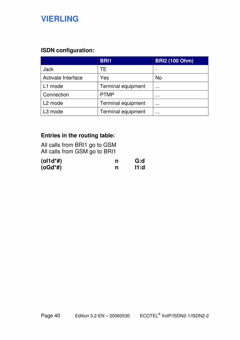
ISDN configuration:
BRI1 BRI2 (100 Ohm)
Jack TE -
Activate Interface Yes No
L1 mode Terminal equipment ...
Connection PTMP ...
L2 mode Terminal equipment ...
L3 mode Terminal equipment ...
Entries in the routing table:
All calls from BRI1 go to GSM All calls from GSM go to BRI1
(oI1d*#) n G:d (oGd*#) n I1:d
VIERLING
ECOTEL® VoIP/ISDN2-1/ISDN2-2 Edition 3.2-EN – 20060530 Page 41
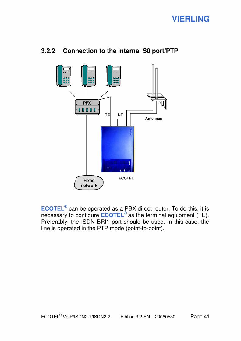
3.2.2 Connection to the internal S0 port/PTP
NT TE
Fixed network
Antennas
ECOTEL
ECOTEL® can be operated as a PBX direct router. To do this, it is
necessary to configure ECOTEL®
as the terminal equipment (TE). Preferably, the ISDN BRI1 port should be used. In this case, the line is operated in the PTP mode (point-to-point).

VIERLING
Page 42 Edition 3.2-EN – 20060530 ECOTEL® VoIP/ISDN2-1/ISDN2-2
ISDN configuration:
BRI1 BRI2 (100 Ohm)
Jack TE ...
Activate Interface Yes No
L1 mode Terminal equipment ...
Connection PTP ...
L2 mode Terminal equipment ...
L3 mode Terminal equipment ...
Entries in the routing table:
All calls from BRI1 go to GSM All calls from GSM go to BRI1
(oI1d*#) n G:d (oGd*#) n I1:d
VIERLING
ECOTEL® VoIP/ISDN2-1/ISDN2-2 Edition 3.2-EN – 20060530 Page 43
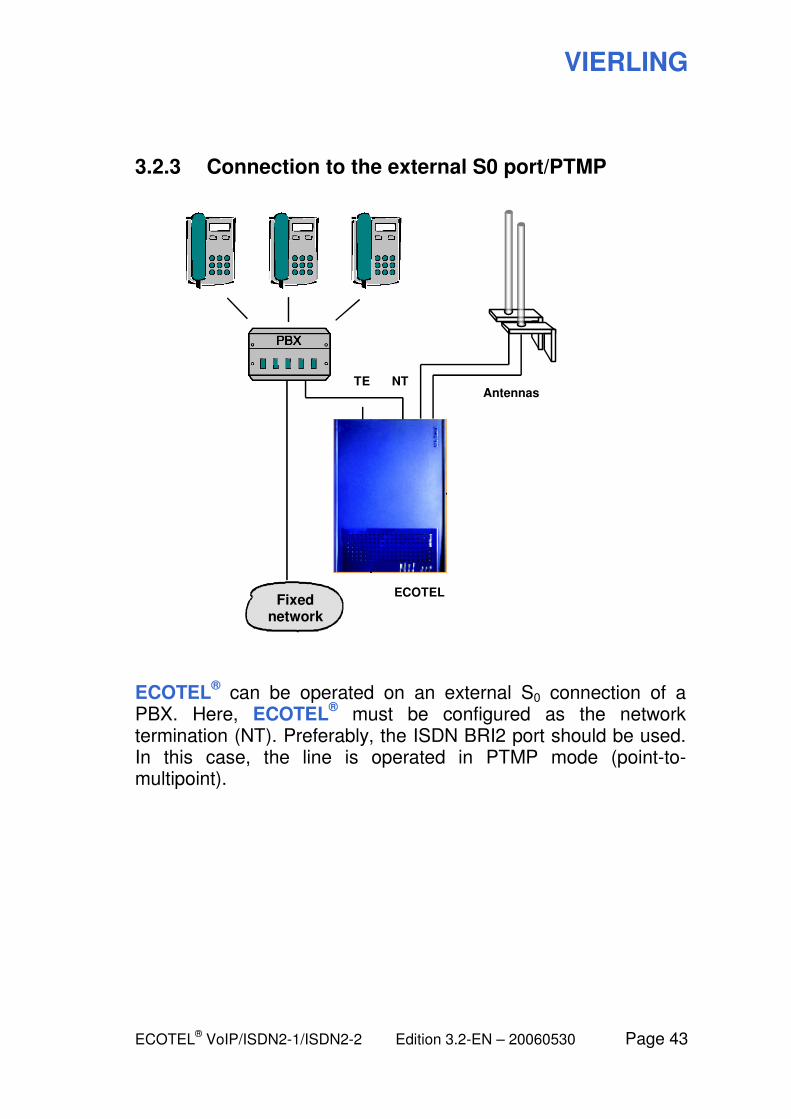
3.2.3 Connection to the external S0 port/PTMP
NT TE
Fixed network
Antennas
ECOTEL
ECOTEL® can be operated on an external S0 connection of a
PBX. Here, ECOTEL® must be configured as the network
termination (NT). Preferably, the ISDN BRI2 port should be used. In this case, the line is operated in PTMP mode (point-to-multipoint).

VIERLING
Page 44 Edition 3.2-EN – 20060530 ECOTEL® VoIP/ISDN2-1/ISDN2-2
ISDN configuration:
BRI1 BRI2 (100 Ohm)
Jack - NT
Activate Interface No Yes
L1 mode ... Network
Connection ... PTMP
L2 mode ... Network
L3 mode ... Network
Entries in the routing table:
All calls from BRI2 go to GSM All calls from GSM go to BRI2
(oI2d*#) n G:d (oGd*#) n I2:d
Note: This configuration is the factory default for ECOTEL
®.
VIERLING
ECOTEL® VoIP/ISDN2-1/ISDN2-2 Edition 3.2-EN – 20060530 Page 45
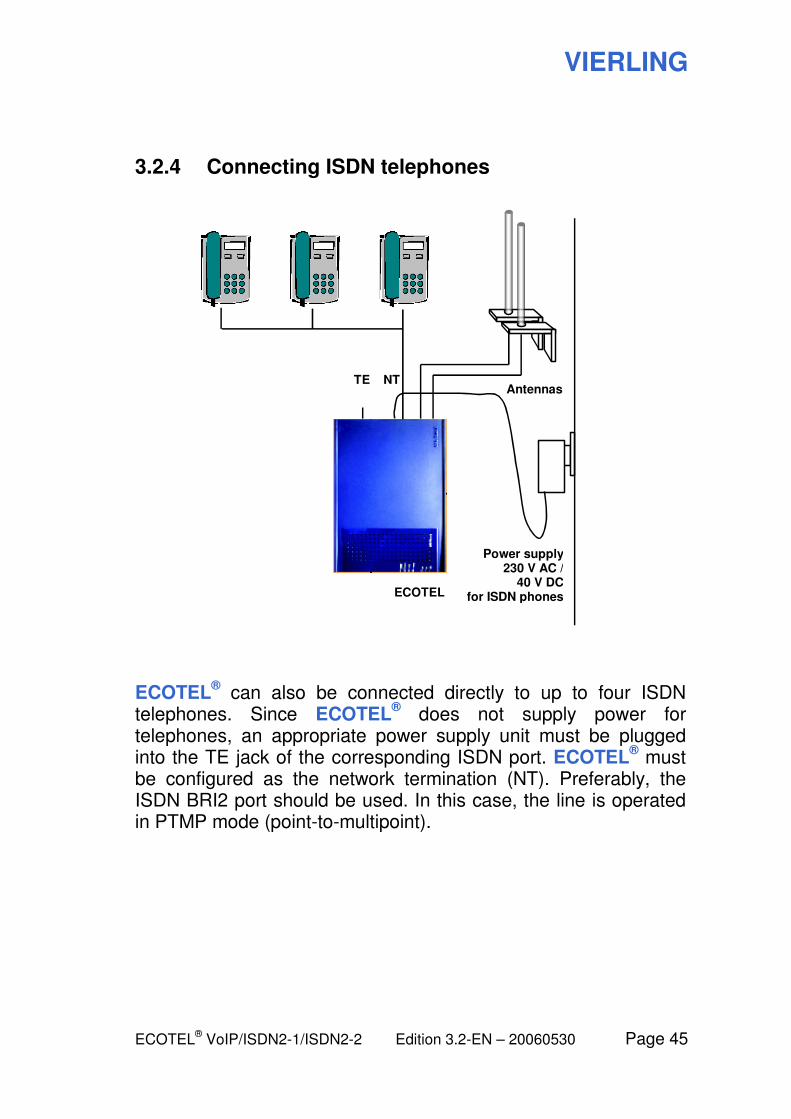
3.2.4 Connecting ISDN telephones
NT TE Antennas
ECOTEL
Power supply 230 V AC /
40 V DCfor ISDN phones
ECOTEL® can also be connected directly to up to four ISDN
telephones. Since ECOTEL® does not supply power for
telephones, an appropriate power supply unit must be plugged into the TE jack of the corresponding ISDN port. ECOTEL
® must
be configured as the network termination (NT). Preferably, the ISDN BRI2 port should be used. In this case, the line is operated in PTMP mode (point-to-multipoint).
VIERLING
Page 46 Edition 3.2-EN – 20060530 ECOTEL® VoIP/ISDN2-1/ISDN2-2
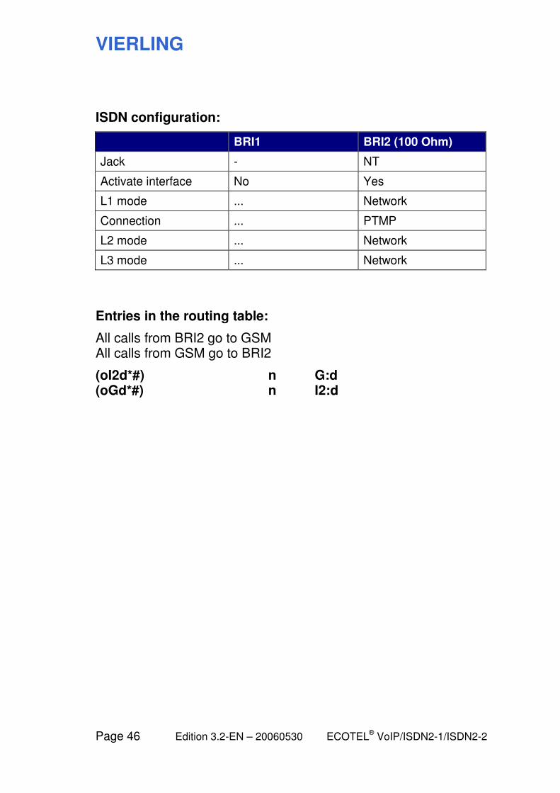
ISDN configuration:
BRI1 BRI2 (100 Ohm)
Jack - NT
Activate interface No Yes
L1 mode ... Network
Connection ... PTMP
L2 mode ... Network
L3 mode ... Network
Entries in the routing table:
All calls from BRI2 go to GSM All calls from GSM go to BRI2
(oI2d*#) n G:d (oGd*#) n I2:d
VIERLING
ECOTEL® VoIP/ISDN2-1/ISDN2-2 Edition 3.2-EN – 20060530 Page 47
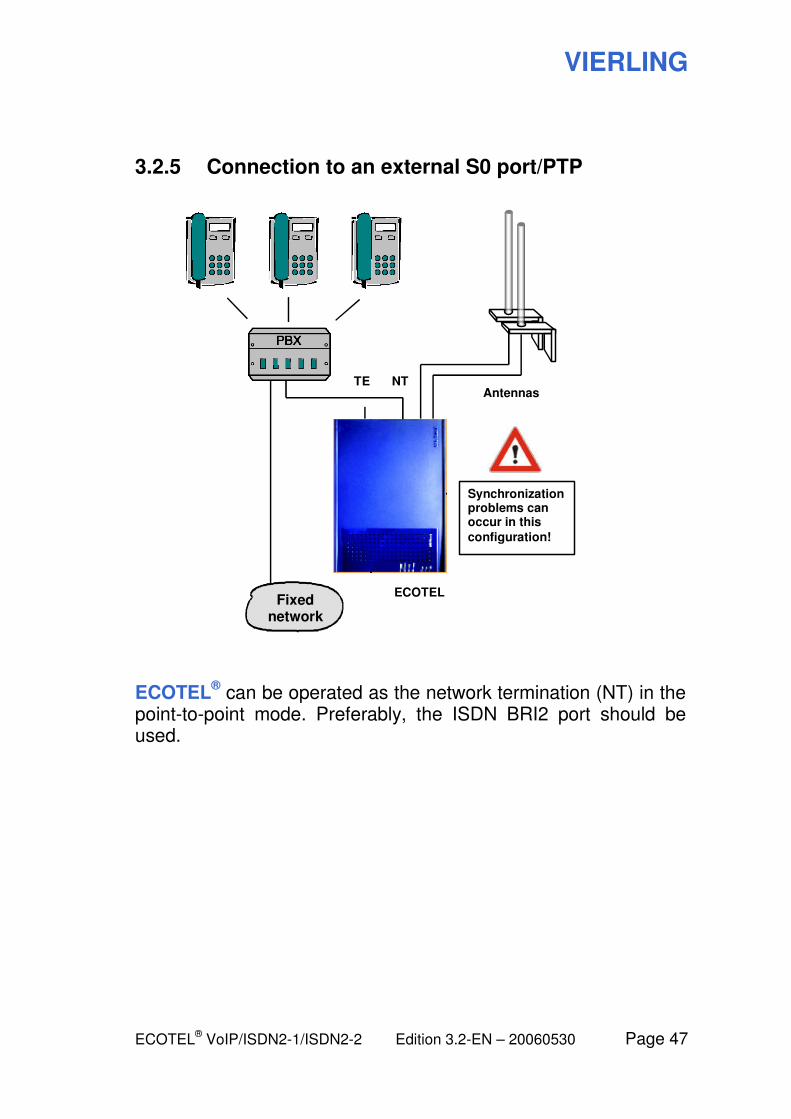
3.2.5 Connection to an external S0 port/PTP
NT TE
Fixed network
Antennas
ECOTEL
Synchronization problems can occur in this
configuration!
ECOTEL® can be operated as the network termination (NT) in the
point-to-point mode. Preferably, the ISDN BRI2 port should be used.
VIERLING
Page 48 Edition 3.2-EN – 20060530 ECOTEL® VoIP/ISDN2-1/ISDN2-2
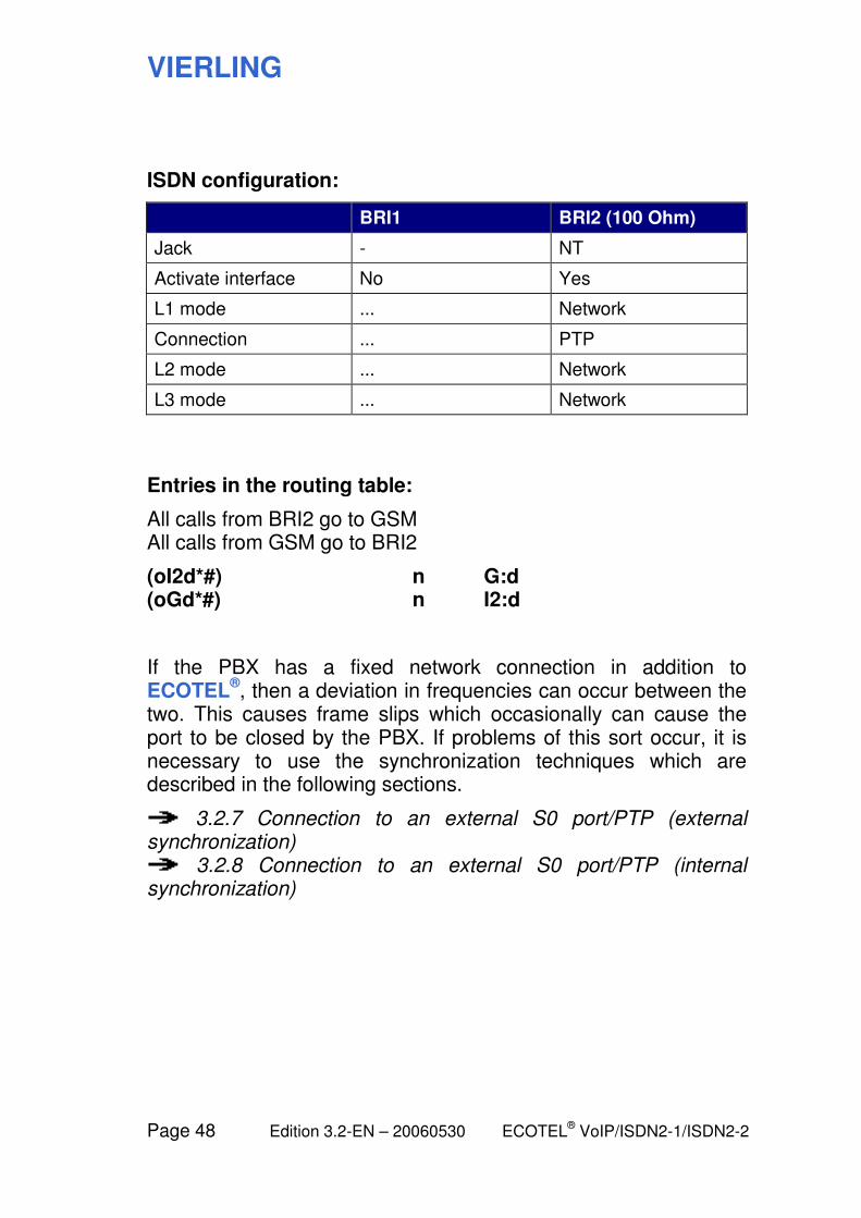
ISDN configuration:
BRI1 BRI2 (100 Ohm)
Jack - NT
Activate interface No Yes
L1 mode ... Network
Connection ... PTP
L2 mode ... Network
L3 mode ... Network
Entries in the routing table:
All calls from BRI2 go to GSM All calls from GSM go to BRI2
(oI2d*#) n G:d (oGd*#) n I2:d
If the PBX has a fixed network connection in addition to ECOTEL
®, then a deviation in frequencies can occur between the
two. This causes frame slips which occasionally can cause the port to be closed by the PBX. If problems of this sort occur, it is necessary to use the synchronization techniques which are described in the following sections.
3.2.7 Connection to an external S0 port/PTP (external synchronization)
3.2.8 Connection to an external S0 port/PTP (internal synchronization)
VIERLING
ECOTEL® VoIP/ISDN2-1/ISDN2-2 Edition 3.2-EN – 20060530 Page 49
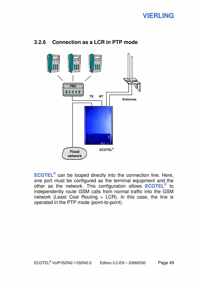
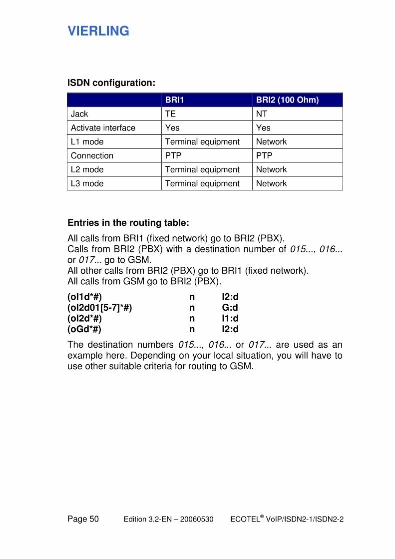
3.2.6 Connection as a LCR in PTP mode
NT TE
Fixed network
Antennas
ECOTEL®
ECOTEL® can be looped directly into the connection line. Here,
one port must be configured as the terminal equipment and the other as the network. This configuration allows ECOTEL
® to
independently route GSM calls from normal traffic into the GSM network (Least Cost Routing = LCR). In this case, the line is operated in the PTP mode (point-to-point).
VIERLING
Page 50 Edition 3.2-EN – 20060530 ECOTEL® VoIP/ISDN2-1/ISDN2-2
ISDN configuration:
BRI1 BRI2 (100 Ohm)
Jack TE NT
Activate interface Yes Yes
L1 mode Terminal equipment Network
Connection PTP PTP
L2 mode Terminal equipment Network
L3 mode Terminal equipment Network
Entries in the routing table:
All calls from BRI1 (fixed network) go to BRI2 (PBX). Calls from BRI2 (PBX) with a destination number of 015..., 016... or 017... go to GSM. All other calls from BRI2 (PBX) go to BRI1 (fixed network). All calls from GSM go to BRI2 (PBX).
(oI1d*#) n I2:d (oI2d01[5-7]*#) n G:d (oI2d*#) n I1:d (oGd*#) n I2:d
The destination numbers 015..., 016... or 017... are used as an example here. Depending on your local situation, you will have to use other suitable criteria for routing to GSM.
VIERLING
ECOTEL® VoIP/ISDN2-1/ISDN2-2 Edition 3.2-EN – 20060530 Page 51
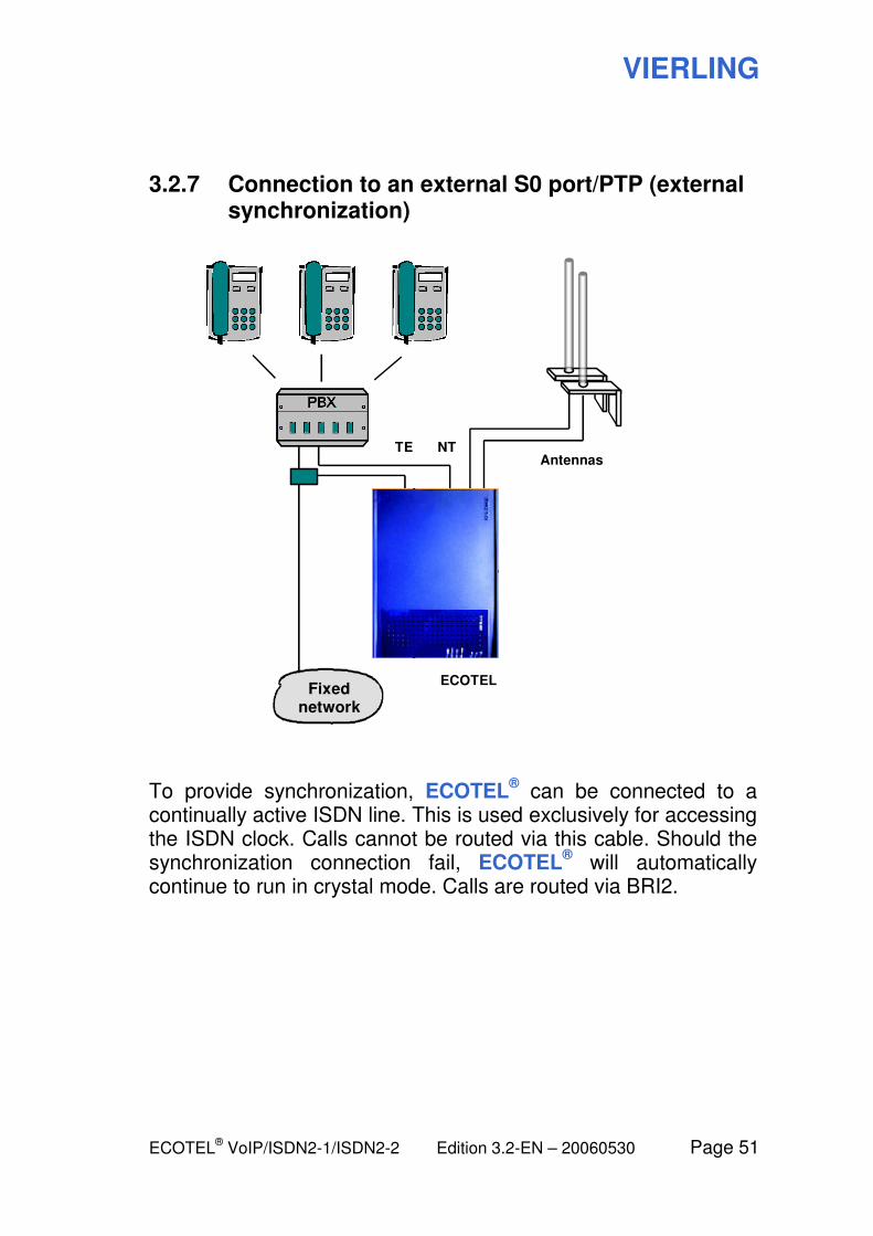
3.2.7 Connection to an external S0 port/PTP (external synchronization)
NT TE
Fixed network
Antennas
ECOTEL
To provide synchronization, ECOTEL® can be connected to a
continually active ISDN line. This is used exclusively for accessing the ISDN clock. Calls cannot be routed via this cable. Should the synchronization connection fail, ECOTEL
® will automatically
continue to run in crystal mode. Calls are routed via BRI2.
VIERLING
Page 52 Edition 3.2-EN – 20060530 ECOTEL® VoIP/ISDN2-1/ISDN2-2
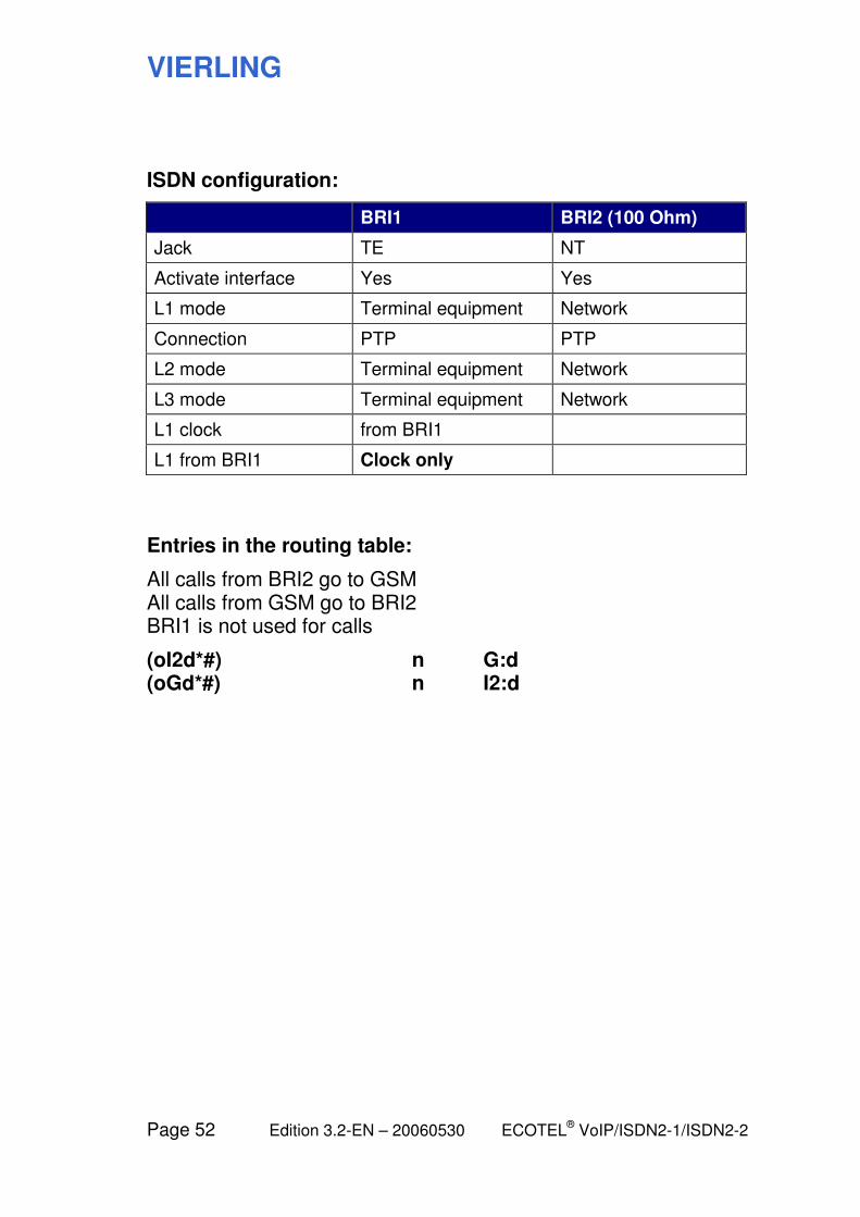
ISDN configuration:
BRI1 BRI2 (100 Ohm)
Jack TE NT
Activate interface Yes Yes
L1 mode Terminal equipment Network
Connection PTP PTP
L2 mode Terminal equipment Network
L3 mode Terminal equipment Network
L1 clock from BRI1
L1 from BRI1 Clock only
Entries in the routing table:
All calls from BRI2 go to GSM All calls from GSM go to BRI2 BRI1 is not used for calls
(oI2d*#) n G:d (oGd*#) n I2:d
VIERLING
ECOTEL® VoIP/ISDN2-1/ISDN2-2 Edition 3.2-EN – 20060530 Page 53
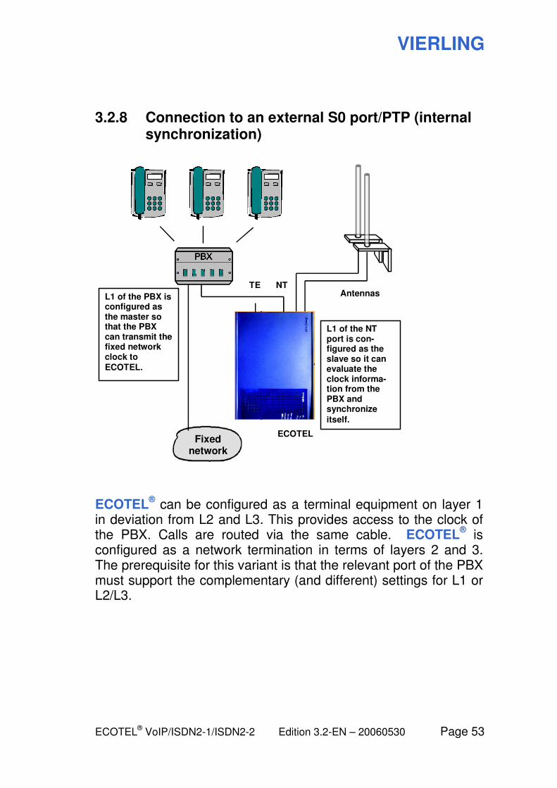
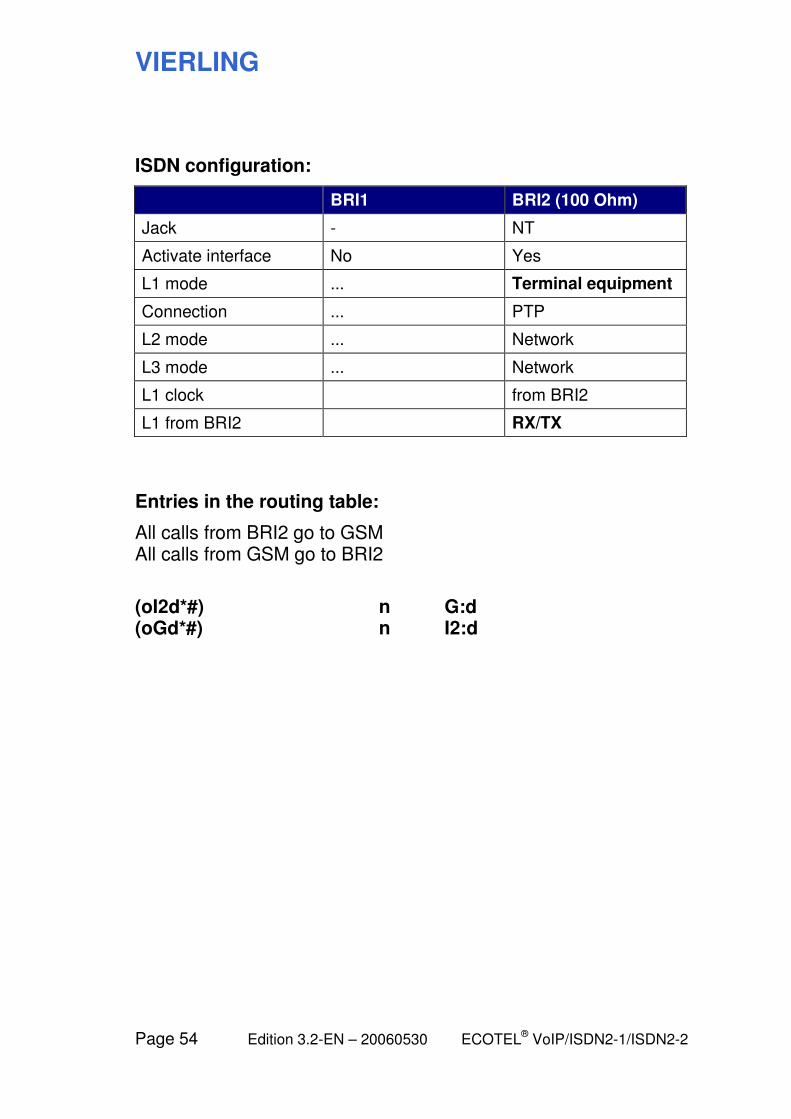
3.2.8 Connection to an external S0 port/PTP (internal synchronization)
NT TE
Fixed network
Antennas
ECOTEL
L1 of the NT port is con- figured as the slave so it can evaluate the clock informa- tion from the PBX and synchronize
itself.
L1 of the PBX is configured as the master so that the PBX can transmit the fixed network clock to ECOTEL.
ECOTEL® can be configured as a terminal equipment on layer 1
in deviation from L2 and L3. This provides access to the clock of the PBX. Calls are routed via the same cable. ECOTEL
® is
configured as a network termination in terms of layers 2 and 3. The prerequisite for this variant is that the relevant port of the PBX must support the complementary (and different) settings for L1 or L2/L3.
VIERLING
Page 54 Edition 3.2-EN – 20060530 ECOTEL® VoIP/ISDN2-1/ISDN2-2
ISDN configuration:
BRI1 BRI2 (100 Ohm)
Jack - NT
Activate interface No Yes
L1 mode ... Terminal equipment
Connection ... PTP
L2 mode ... Network
L3 mode ... Network
L1 clock from BRI2
L1 from BRI2 RX/TX
Entries in the routing table:
All calls from BRI2 go to GSM All calls from GSM go to BRI2
(oI2d*#) n G:d (oGd*#) n I2:d
VIERLING
ECOTEL® VoIP/ISDN2-1/ISDN2-2 Edition 3.2-EN – 20060530 Page 55
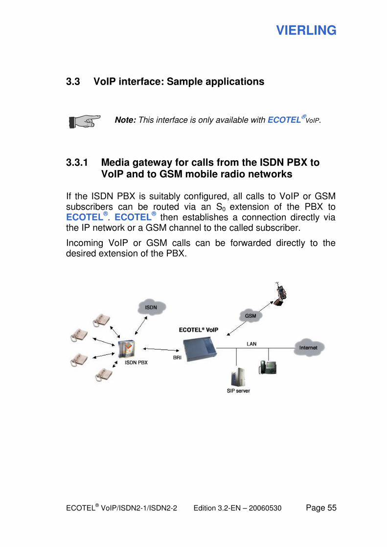
3.3 VoIP interface: Sample applications
Note: This interface is only available with ECOTEL
®VoIP.
3.3.1 Media gateway for calls from the ISDN PBX to VoIP and to GSM mobile radio networks
If the ISDN PBX is suitably configured, all calls to VoIP or GSM subscribers can be routed via an S0 extension of the PBX to ECOTEL
®. ECOTEL
® then establishes a connection directly via
the IP network or a GSM channel to the called subscriber.
Incoming VoIP or GSM calls can be forwarded directly to the desired extension of the PBX.
VIERLING
Page 56 Edition 3.2-EN – 20060530 ECOTEL® VoIP/ISDN2-1/ISDN2-2
ISDN configuration, variant 1:
As in the following ISDN example:
3.2.1 Connection to the internal S0 port/PTMP
(ECOTEL® on an extension of the PBX)
Entries in the routing table:
All calls from VoIP go to BRI1 (PBX). Calls from BRI1 (PBX) with a destination number of 015..., 016... or 017... go to GSM. All other calls from BRI1 (PBX) go to VoIP. All calls from GSM go to BRI1 (PBX).
(oVd*#) n I1:d (oI1d01[5-7]*#) n G:d (oI1d*#) n V:d (oGd*#) n I1:d
The destination numbers 015..., 016... or 017... are used as an example here. Depending on your local situation, you will have to use other suitable criteria for routing to GSM.
ISDN configuration, variant 2:
As in the following ISDN example:
3.2.3 Connection to the external S0 port/PTMP
(ECOTEL® on the exchange line of the PBX)
Entries in the routing table:
All calls from VoIP go to BRI2 (PBX). Calls from BRI2 (PBX) with a destination number of 015..., 016... or 017... go to GSM. All other calls from BRI2 (PBX) go to VoIP. All calls from GSM go to BRI2 (PBX).
VIERLING
ECOTEL® VoIP/ISDN2-1/ISDN2-2 Edition 3.2-EN – 20060530 Page 57
(oVd*#) n I2:d (oI2d01[5-7]*#) n G:d (oI2d*#) n V:d (oGd*#) n I2:d
The destination numbers 015..., 016... or 017... are used as an example here. Depending on your local situation, you will have to use other suitable criteria for routing to GSM.
VIERLING
Page 58 Edition 3.2-EN – 20060530 ECOTEL® VoIP/ISDN2-1/ISDN2-2
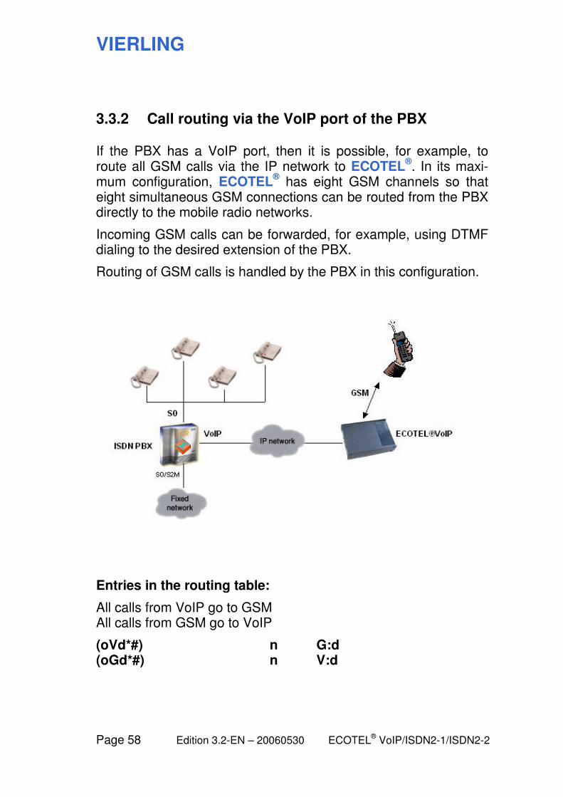
3.3.2 Call routing via the VoIP port of the PBX
If the PBX has a VoIP port, then it is possible, for example, to route all GSM calls via the IP network to ECOTEL
®. In its maxi-
mum configuration, ECOTEL® has eight GSM channels so that
eight simultaneous GSM connections can be routed from the PBX directly to the mobile radio networks.
Incoming GSM calls can be forwarded, for example, using DTMF dialing to the desired extension of the PBX.
Routing of GSM calls is handled by the PBX in this configuration.
Entries in the routing table:
All calls from VoIP go to GSM All calls from GSM go to VoIP
(oVd*#) n G:d (oGd*#) n V:d
VIERLING
ECOTEL® VoIP/ISDN2-1/ISDN2-2 Edition 3.2-EN – 20060530 Page 59
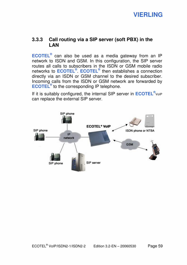
3.3.3 Call routing via a SIP server (soft PBX) in the LAN
ECOTEL® can also be used as a media gateway from an IP
network to ISDN and GSM. In this configuration, the SIP server routes all calls to subscribers in the ISDN or GSM mobile radio networks to ECOTEL
®. ECOTEL
® then establishes a connection
directly via an ISDN or GSM channel to the desired subscriber. Incoming calls from the ISDN or GSM network are forwarded by ECOTEL
® to the corresponding IP telephone.
If it is suitably configured, the internal SIP server in ECOTEL®
VoIP can replace the external SIP server.
VIERLING
Page 60 Edition 3.2-EN – 20060530 ECOTEL® VoIP/ISDN2-1/ISDN2-2
ISDN configuration:
As in the following ISDN example:
3.2.1 Connection to the internal S0 port/PTMP
Entries in the routing table:
Calls from VoIP with a destination number of 015..., 016... or 017... go to GSM. All other calls from VoIP go to BRI1 (ISDN). All calls from BRI1 (ISDN) go to VoIP. All calls from GSM go to VoIP.
(oVd01[5-7]*#) n G:d (oVd*#) n I1:d (oI1d*#) n V:d (oGd*#) n V:d
The destination numbers 015..., 016... or 017... are used as an example here. Depending on your local situation, you will have to use other suitable criteria for routing to GSM.
VIERLING
ECOTEL® VoIP/ISDN2-1/ISDN2-2 Edition 3.2-EN – 20060530 Page 61
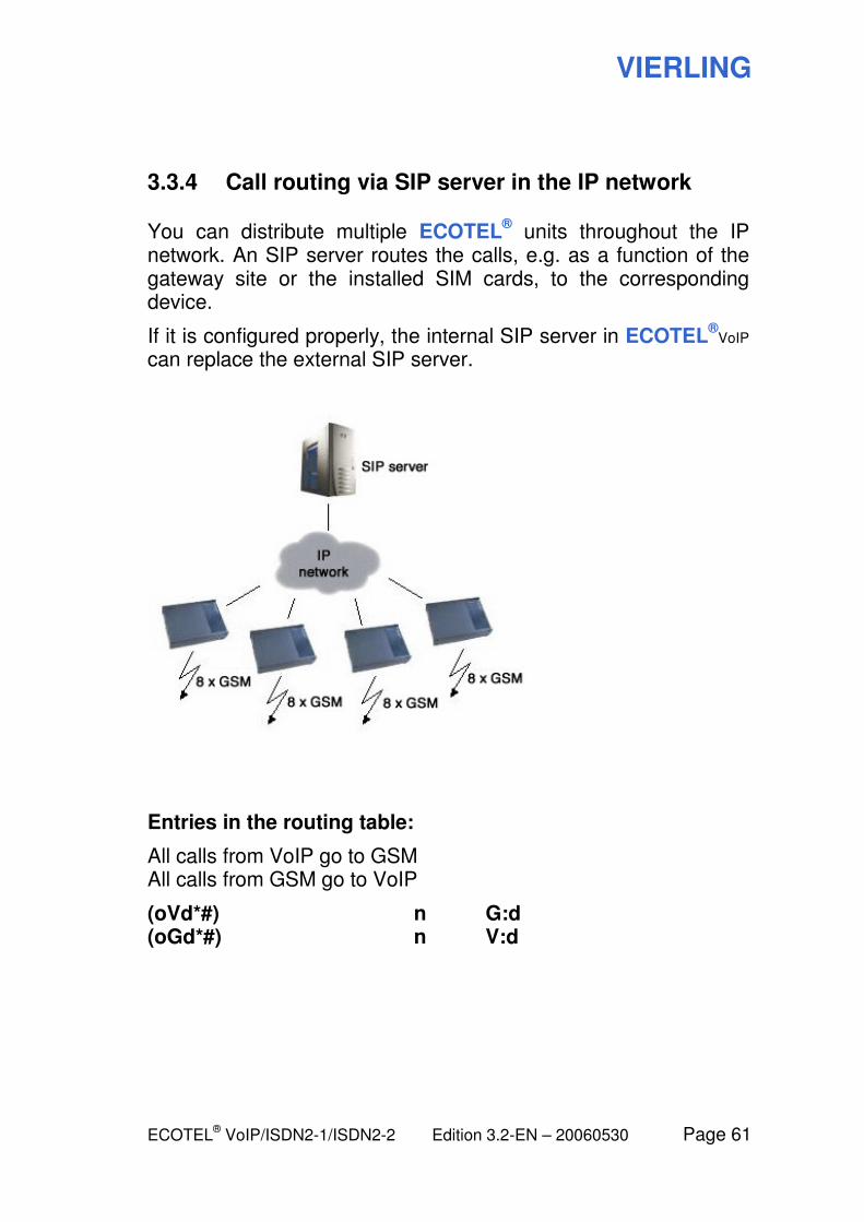
3.3.4 Call routing via SIP server in the IP network
You can distribute multiple ECOTEL® units throughout the IP
network. An SIP server routes the calls, e.g. as a function of the gateway site or the installed SIM cards, to the corresponding device.
If it is configured properly, the internal SIP server in ECOTEL®
VoIP can replace the external SIP server.
Entries in the routing table:
All calls from VoIP go to GSM All calls from GSM go to VoIP
(oVd*#) n G:d (oGd*#) n V:d
VIERLING
Page 62 Edition 3.2-EN – 20060530 ECOTEL® VoIP/ISDN2-1/ISDN2-2
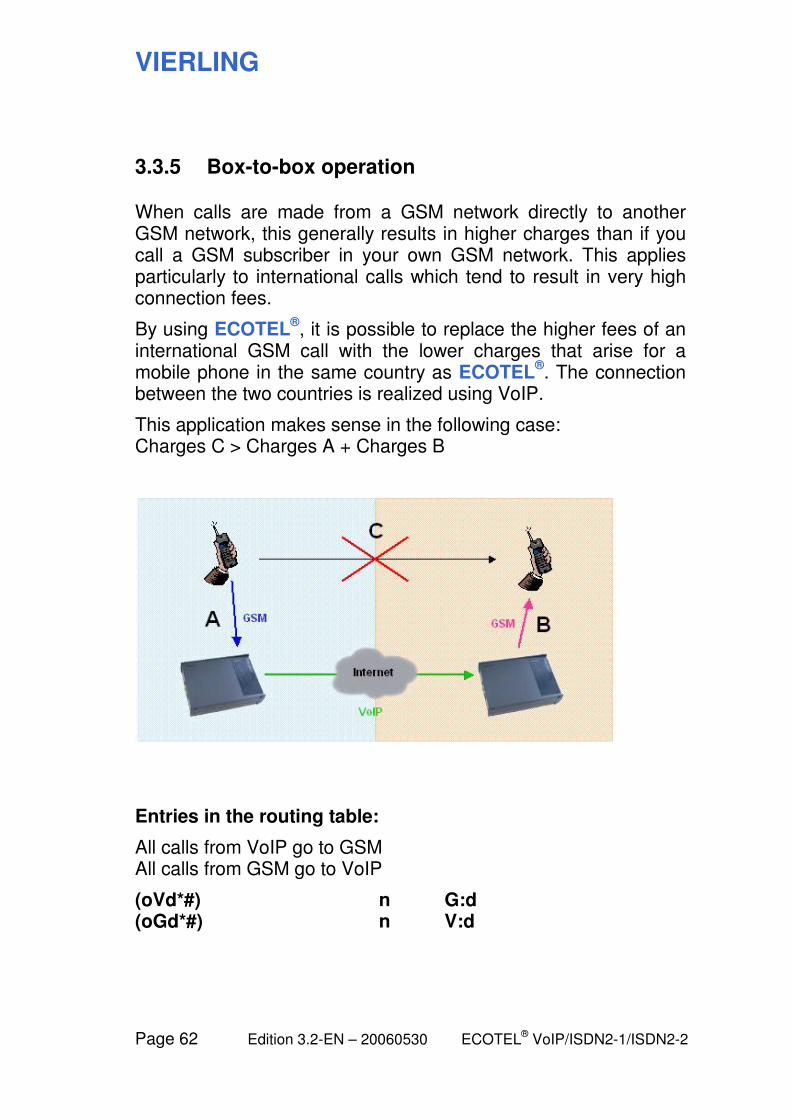
3.3.5 Box-to-box operation
When calls are made from a GSM network directly to another GSM network, this generally results in higher charges than if you call a GSM subscriber in your own GSM network. This applies particularly to international calls which tend to result in very high connection fees.
By using ECOTEL®, it is possible to replace the higher fees of an
international GSM call with the lower charges that arise for a mobile phone in the same country as ECOTEL
®. The connection
between the two countries is realized using VoIP.
This application makes sense in the following case: Charges C > Charges A + Charges B
Entries in the routing table:
All calls from VoIP go to GSM All calls from GSM go to VoIP
(oVd*#) n G:d (oGd*#) n V:d
VIERLING
ECOTEL® VoIP/ISDN2-1/ISDN2-2 Edition 3.2-EN – 20060530 Page 63
3.4 Additional functions
3.4.1 Call hold switching between GSM and ISDN subscribers
Note: This feature is currently available only with ECOTEL
®ISDN2-1.
It is possible to switch between arbitrary GSM or ISDN sub-scribers, i.e. during a call one of the two subscribers can make a call to a third party. The connection to the original party is held during this time. You can then switch between the two calls.
The call hold function in ECOTEL® does not use the call hold
supplementary service provided in the GSM network or the ISDN network. As a result, two GSM channels (ISDN B channels) are always required in case of participation of two GSM subscribers (ISDN subscribers). However, this means that the function works even if the GSM call hold supplementary service is not supported by the SIM card which is used.
For more details, see:
7.4 Call hold switching between subscribers
VIERLING
Page 64 Edition 3.2-EN – 20060530 ECOTEL® VoIP/ISDN2-1/ISDN2-2
3.4.2 User registration
Note: This feature is only available with ECOTEL
®VoIP.
ECOTEL®
VoIP has an internal SIP server. Terminal devices (SIP telephones, softphones) that want to make phone calls using the VoIP interface provided by ECOTEL
® can register there. This also
applies to external SIP proxies or SIP providers that want to forward calls to ECOTEL
®.
The User Registration module is provided for managing the authorized users that are known to ECOTEL
®.
6.9 User Registration module
A user who is known to ECOTEL® can register with ECOTEL
®,
assuming the user is connected to ECOTEL® via an IP network,
for the duration of the connection. The user is considered to be "reachable" and can make and receive calls.
User registration can take place either with or without authentication.
When the device is shipped, any user is allowed to register without authentication. We recommend that you keep this setting only if you intend to use ECOTEL
® exclusively in an internal
network with a secure firewall in place.
VIERLING
ECOTEL® VoIP/ISDN2-1/ISDN2-2 Edition 3.2-EN – 20060530 Page 65
3.4.3 SIP outbounds (SIP proxies and SIP providers)
Note: These feature is only available with ECOTEL
®VoIP.
Outgoing calls to a SIP proxy or SIP provider
Initially, ECOTEL® can route VoIP calls only to subscribers that it
knows, i.e. subscribers that are registered with its own SIP server. For calls to other subscribers, ECOTEL
® needs partners that
support forwarding to other VoIP networks. There are two different cases: SIP proxies and SIP providers. This manual refers to both together as SIP outbounds.
To make a SIP proxy or SIP provider usable for ECOTEL®, you
will need to enter certain setup data. This is handled in the Gateway Configuration module under VoIP > SIP Outbound 1 (2, 3, ...).
6.3.10 Gateway Configuration: SIP Outbound 1..n
Differences between a SIP proxy and a SIP provider
From the viewpoint of ECOTEL®, the following distinction is
relevant:
With a SIP provider, ECOTEL® logs in like a terminal device.
Providers also generally require authentication with a user identifier and password. You can obtain this data from your SIP provider. The actual terminal device that is behind ECOTEL
®, e.g.
a VoIP telephone, is invisible to the provider.
If you are operating your own SIP server (e.g. Asterisk) in an internal network, it should be configured as a SIP proxy from the viewpoint of ECOTEL
®. From the viewpoint of the SIP server,
ECOTEL® also behaves like a SIP proxy. ECOTEL
® has to log
into the SIP proxy with the user name known there; authentication is generally not required. For each call from a VoIP terminal device, ECOTEL
® passes along its user name to the SIP proxy. In
VIERLING
Page 66 Edition 3.2-EN – 20060530 ECOTEL® VoIP/ISDN2-1/ISDN2-2
this case, the authentication is handled between the SIP proxy and the caller. If the caller is not a VoIP subscriber (e.g. a GSM subscriber), then ECOTEL
® will act as a terminal device itself with respect to a SIP
proxy.
Incoming calls from a SIP Outbound
If you want ECOTEL® to also accept incoming calls from a SIP
outbound, it will need to be able to register with ECOTEL® as a
user. You will need to make an appropriate entry for the SIP proxy or SIP provider in the User Registration module.
6.9 User Registration module
SIP outbounds and routing table
In the routing table, you can (or must) specify the SIP outbound for routing an outgoing VoIP call. The virtual port names V1, V2, ... are used which correspond to SIP outbounds 1, 2, ... For calls without a SIP outbound (i.e. to SIP telephones that are registered with the SIP server provided in ECOTEL
®), select the
virtual port V.
VIERLING
ECOTEL® VoIP/ISDN2-1/ISDN2-2 Edition 3.2-EN – 20060530 Page 67
3.4.4 SIM management
Note: This feature is not available with ECOTEL
®ISDN2-1.
ECOTEL® allows you to use multiple SIM cards for the same
GSM channel. You can specify which SIM cards to use at which times in order to take advantage of the best rates. ECOTEL
® can
automatically switch between SIM cards, e.g. when a card’s balance runs out.
You will need to use SIM cardholders if you want to switch between different cards.
9.5 SIM cardholder installation
You can make the relevant settings in the SIM Management module.
6.8 SIM Management module
ECOTEL®
VoIP and ECOTEL®
ISDN2-2 may also be operated using an external SIM server instead of locally installed SIM cards. For this purpose, a SIM emulation board must be installed in the cardholder slot. This board will connect to the SIM server and emulate the SIM cards present there with respect to ECOTEL
®.
The SIM emulation board is not included with ECOTEL®.
VIERLING
Page 68 Edition 3.2-EN – 20060530 ECOTEL® VoIP/ISDN2-1/ISDN2-2
3.4.5 CDRs in ECOTEL
If recording of call detail records (CDR) is activated, a new CDR file is created in ECOTEL
® each day and the CDRs which occur
during the day are saved in the file.
CDR recording must be activated separately for each interface in the Gateway Configuration module under ISDN > ISDN Inter-face n (or GSM > GSM Interface n or VoIP > VoIP Interface) using the Generate call records checkbox there.
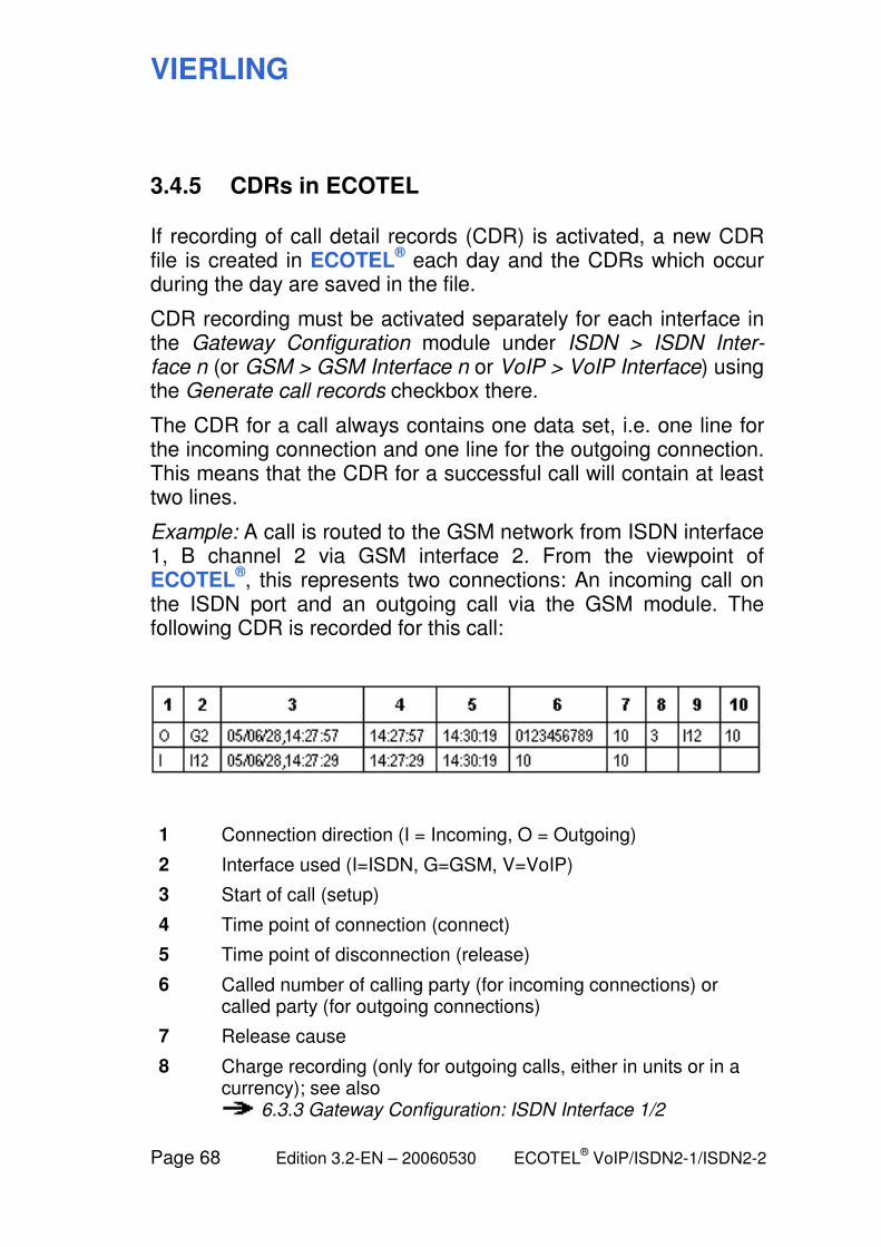
The CDR for a call always contains one data set, i.e. one line for the incoming connection and one line for the outgoing connection. This means that the CDR for a successful call will contain at least two lines.
Example: A call is routed to the GSM network from ISDN interface 1, B channel 2 via GSM interface 2. From the viewpoint of ECOTEL
®, this represents two connections: An incoming call on
the ISDN port and an outgoing call via the GSM module. The following CDR is recorded for this call:
1 Connection direction (I = Incoming, O = Outgoing)
2 Interface used (I=ISDN, G=GSM, V=VoIP)
3 Start of call (setup)
4 Time point of connection (connect)
5 Time point of disconnection (release)
6 Called number of calling party (for incoming connections) or called party (for outgoing connections)
7 Release cause
8 Charge recording (only for outgoing calls, either in units or in a currency); see also
6.3.3 Gateway Configuration: ISDN Interface 1/2
VIERLING
ECOTEL® VoIP/ISDN2-1/ISDN2-2 Edition 3.2-EN – 20060530 Page 69
9 Interface used for the incoming call which was routed via ECOTEL
®
10 Telephone number of the calling subscriber who made a call via ECOTEL
®
Special case: Logging is as follows when using callback:
– The first CDR logs the incoming call from subscriber A.
– The second CDR contains the first outgoing call to A
(where A is the called party and ECOTEL® is the calling
party) with reference to the incoming call.
– The third CDR contains the second outgoing call
(B is the called party and A the calling party) with reference to the first outgoing call.
VIERLING
Page 70 Edition 3.2-EN – 20060530 ECOTEL® VoIP/ISDN2-1/ISDN2-2
3.4.6 Adaptive callbacks
The Adaptive Callbacks function (rerouting) writes the phone numbers of the calling and called subscribers into an internal list maintained by ECOTEL
® for all failed calls from the ISDN
interface to the GSM network. The validity duration for the entries in this list can be specified by the user. If the GSM subscriber which was not reached previously calls ECOTEL
® within the set
time, he is automatically forwarded to the telephone number which previously attempted to reach him without success.
Make the necessary settings in the Gateway Configuration module under ISDN Interface 1 (or 2).
There are two ways to setting up the entries in the ECOTEL®:
Automatic adaptive callbacks
For automatic adaptive callbacks, the telephone number of the calling party and the called party are automatically saved in ECOTEL
® for the time set under Automatic callbacks valid for ...
Manual adaptive callbacks
If Automatic Callbacks are deactivated, then the calling subscriber can manually enter his telephone number and that of the called party into the callback list. He must enter the sequence *0## on his telephone keypad prior to hanging up. The data are then saved for 60 minutes in the list. If another interval besides the default value of 60 minutes is required, then you must enter the sequence *0#time in minutes# (e.g. *0#150# for 150 minutes). You can enter values from 0 to 1440 minutes (= 1 day). The callback list is updated only every five minutes. You can delete your entry with *0#0#.
– Example 1: *0#150# means that if the person who was not
reached calls back within 150 minutes, they are to be automatically connected to the subscriber who previously tried to call them.
VIERLING
ECOTEL® VoIP/ISDN2-1/ISDN2-2 Edition 3.2-EN – 20060530 Page 71
You can also set up an entry in the call list without a current call by entering the sequence *0#Telephone number## (storage for 60 minutes) or *0#Telephone number#Time in minutes# (storage for e.g. 150 minutes).
– Example 2: *0#0123456789#150# means that if the
subscriber with the telephone number 0123456789 calls the GSM module of ECOTEL
® within 150 minutes, he is to
be automatically connected to the subscriber who wrote this entry into the callback list.
You can delete to an arbitrary entry from the callback list by entering the sequence *0#Telephone number#0#
– Example 3: *0#0123456789#0# means that the entry for
the subscriber with the telephone number 0123456789 is to be deleted from the callback list. If this subscriber calls the GSM module of ECOTEL
®, he will not be forwarded
automatically.
Handling of multiple unsuccessful calls
If multiple GSM subscribers are not reached from the same extension, a callback entry is written into the list for each attempt.
If several different extensions call the same GSM subscriber without reaching that person, then each new entry overwrites the previous one. This means that only the entry representing the most recent attempt remains in the callback list.
VIERLING
Page 72 Edition 3.2-EN – 20060530 ECOTEL® VoIP/ISDN2-1/ISDN2-2
3.4.7 Callback request via SMS
ECOTEL® has a function which makes it possible, in case of the
failed call from a PBX to a GSM subscriber, to automatically send an SMS message to the subscriber. With this callback request, the desired party receives notification that an attempt was made to reach him and that he should return the call, for example.
Make the necessary settings in the Gateway Configuration module under GSM Interface 1 (or 2, 3, ...) > Callback SMS.
You can enter whatever text you wish to use for the SMS message which forms the callback request.
The %m wildcard automatically inserts the telephone number of the SIM card via which the subscriber was called into the SMS message. The extension of the calling subscriber can be inserted into the SMS text with the %e wildcard.
Example: “Please call back %m or %e .”
Transmission of the SMS message can be initiated in two ways:
In the setting By request of the calling party, the SMS message is sent only if the calling subscriber enters the character sequence *1# using DTMF dialing. The callback request via SMS can be entered only if the call was not successful. If the voicemail is reached, this is considered to be a successful connection.
If the setting is Automatic for each failed call, the SMS message with the callback request is sent automatically as soon as the call fails.
VIERLING
ECOTEL® VoIP/ISDN2-1/ISDN2-2 Edition 3.2-EN – 20060530 Page 73
3.4.8 SMS functions
ECOTEL® supports transmission of SMS messages. For this
purpose, ECOTEL® provides a GSM07.07 interface for USB and
IP/Telnet (not with ECOTEL®
ISDN2-1) or for RS232 and IP/Telnet (with ECOTEL
®ISDN2-1).
Software is available free of charge for the RS232 interface. Transmission, reception and storage of SMS messages can be managed using SmeaSyPro.EXE.
Conversion of e-mail to SMS (or SMS to e-mail) can be implemented using the application ECOTEL
® SMbaSic (Mail
Manager). This program is available separately. For a detailed description, see the documentation on the CD-ROM.
3.4.9 Dialing in via the Internet
Note: This is currently possible only with ECOTEL
®ISDN2-1.
ECOTEL®
ISDN2-1 offers asynchronous PPP for RS232 and IP/Telnet in order to allow dial-in via the Internet (CSD and GPRS).
Software is available free of charge for the RS232 interface. The driver ECI2_1Modem.inf supports multiple device drivers for the different models.
VIERLING
Page 74 Edition 3.2-EN – 20060530 ECOTEL® VoIP/ISDN2-1/ISDN2-2
4 Usage of the configuration software
VIERLING
ECOTEL® VoIP/ISDN2-1/ISDN2-2 Edition 3.2-EN – 20060530 Page 75
4.1 Overview: How to configure ECOTEL VoIP
In order to configure ECOTEL®, you will need a computer (PC,
laptop) on which the ECOTEL® Service Gear configuration
software is installed.
Accessing ECOTEL
From your computer, you have different ways of accessing ECOTEL
®:
– Via IP (Ethernet / LAN, WAN)
– Via USB
– Via the serial interface (ECOTEL®
ISDN2-1 only)
– Via a modem
The relevant details are described in the following sections.
4.3 Connecting the computer and ECOTEL
Configuration files
As soon as a connection has been established between your computer and the device (ECOTEL
®), you can configure the
device by downloading a suitably prepared configuration file.
The configuration software modules automatically use the proper file type. The following information is provided for general orientation.
VIERLING
Page 76 Edition 3.2-EN – 20060530 ECOTEL® VoIP/ISDN2-1/ISDN2-2
File management
There are the following different configuration files for each device:
– ECOTEL.UPB for the general settings
– ECOTEL.BSB for the special basic settings of the ISDN
interfaces
– ECOTEL.SMC for the SIM cards settings (not in
ECOTEL®
ISDN2-1)
– USER.TXT as the VoIP user table (only in ECOTEL®
VoIP)
– RTBL.TXT as the routing table
Each of these files is handled using a specific module. You can see the assignments here:
4.2 The ECOTEL Service Gear software
The following section contains more information on processing these files:
4.4 Editing the configuration files
The configuration files (and other files) for one or more devices are managed on your computer in a directory structure which is known as the database. There, you can save variants and backup copies of your configurations and open and modify existing configurations as templates. The configuration files found on the device can be read out using an upload and then edited and resaved.
VIERLING
ECOTEL® VoIP/ISDN2-1/ISDN2-2 Edition 3.2-EN – 20060530 Page 77
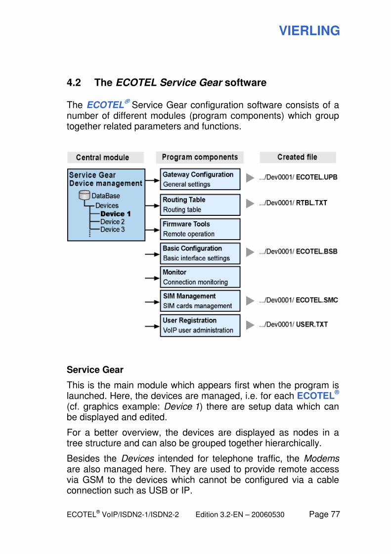
4.2 The ECOTEL Service Gear software
The ECOTEL® Service Gear configuration software consists of a
number of different modules (program components) which group together related parameters and functions.
Service Gear
This is the main module which appears first when the program is launched. Here, the devices are managed, i.e. for each ECOTEL
®
(cf. graphics example: Device 1) there are setup data which can be displayed and edited.
For a better overview, the devices are displayed as nodes in a tree structure and can also be grouped together hierarchically.
Besides the Devices intended for telephone traffic, the Modems are also managed here. They are used to provide remote access via GSM to the devices which cannot be configured via a cable connection such as USB or IP.
VIERLING
Page 78 Edition 3.2-EN – 20060530 ECOTEL® VoIP/ISDN2-1/ISDN2-2
For each device, Service Gear manages a folder in the directory structure of the configuration computer (cf. graphics example: C:\Program Files\Vierling\ECOTEL_Service_Gear\EcotelData\Dev0001\). There, the files are saved which are associated with each device, i.e., the configuration files as well as other data such as CDRs or log files. Together, all of these files are known as the Database.
Navigating between the modules
From Service Gear, you can access the other modules by marking a device and choosing the desired module with Tools > Start > ... Or even shorter: Double click on the device to open the Gateway Configuration module.
The module is opened “for the selected device”, i.e. the data associated with the device are automatically used (folder for file storage, setup data for connecting to the device).
To go from one of the other modules to a different module, you should also use the Tools menu.
If you exit one of these modules, you will be returned to Service Gear.
Note: When you open a module, the Service Gear window will disappear initially. Then, it might take a little while until the new window opens.
For historical reasons, the Gateway Configuration and Basic Configuration modules are still labeled ECOTEL Configuration Software in the title bar. However, you can clearly distinguish the modules based on the entries in the tree view.
Gateway Configuration
This module allows you to make most of the settings required by ECOTEL
®, except for only the basic settings for the ISDN
interfaces and the routing table, which are handled in separate modules.
VIERLING
ECOTEL® VoIP/ISDN2-1/ISDN2-2 Edition 3.2-EN – 20060530 Page 79
All of the parameters which appear here are found in the configuration file ECOTEL.UPB. It must be downloaded to the device after editing in order for the changes to go into effect.
Routing Table
The routing table determines how ECOTEL® handles incoming
connection requests. Here, it is possible to distinguish between a number of different cases depending on the interface or telephone number group. A special syntax is used which allows a great variety of individual settings.
All of the entries which you make here are found in the configuration file RTBL.TXT. It must be downloaded to the device after editing in order for the changes to go into effect.
Firmware Tools
The Firmware Tools module is used to download new firmware and also for all other maintenance tasks which are not linked to the configuration files.
Basic Configuration
In this module, you can make the basic settings for the two ISDN interfaces and the VoIP/LAN interface.
All of the parameters which appear here are found in the configuration file ECOTEL.BSB. It must be downloaded to the device after editing in order for the changes to go into effect.
Monitor
The Monitor displays information about the user connections which are currently underway via the device. This includes data such as the channel status, utilization statistics and current connections.
VIERLING
Page 80 Edition 3.2-EN – 20060530 ECOTEL® VoIP/ISDN2-1/ISDN2-2
SIM Management (not for ECOTEL®
ISDN2-1)
This module handles the data for the SIM cards and determines how to switch between multiple cards for a GSM module.
All of the parameters which appear here are found in the configuration file ECOTEL.SMC. It must be downloaded to the device after editing in order for the changes to go into effect.
User Registration (only with ECOTEL®
VoIP)
You can use this module to manage VoIP users of ECOTEL®.
This includes all of the subscribers who wish to use the VoIP interface provided by ECOTEL
® for incoming or outgoing calls and
need to register beforehand with ECOTEL®.
All of the entries which you make here are found in the configuration file USER.TXT. It must be downloaded to the device after editing in order for the changes to go into effect.
VIERLING
ECOTEL® VoIP/ISDN2-1/ISDN2-2 Edition 3.2-EN – 20060530 Page 81
4.3 Connecting the computer and ECOTEL
In order to be able to access ECOTEL® from your configuration
computer, you first need to establish a connection between the two. There are several possibilities here: Via USB (for ECOTEL
®VoIP and ECOTEL
®ISDN2-2) or serial interface (for
ECOTEL®
ISDN2-1), via IP (LAN, WAN) or via a modem.
Enter your choice in the Service Gear module along with the associated access data using the Properties dialog for the relevant device.
The relevant details are described in the following sections.
VIERLING
Page 82 Edition 3.2-EN – 20060530 ECOTEL® VoIP/ISDN2-1/ISDN2-2
4.3.1 Connecting via IP (LAN, WAN), USB or serial interface
Note: IP: Available with all ECOTEL
® types
USB: Not available with ECOTEL®
ISDN2-1 Serial: Only available with ECOTEL
®ISDN2-1
» Connect the computer and ECOTEL®:
(a) using a connection to a LAN or WAN (Ethernet), or (b) with a USB cable, or (c) with a serial cable
» In the Service Gear module:
Select the device Open the Properties dialogue
» Select the desired option for Access via:
(a) IP (b) USB (c) RS232 (serial)
» Enter the required parameters:
for (a) enter the configuration IP address of ECOTEL®
for (b) choose the COM port for the computer for (c) choose the COM port for the computer
Note: The factory default IP address of the configuration interface of ECOTEL
® is 192.168.10.10
» Enter the security code that your computer must use for
authentication with ECOTEL® (factory default: empty)
» OK
This information allows your computer to automatically connect to ECOTEL
® each time you execute a corresponding function.
VIERLING
ECOTEL® VoIP/ISDN2-1/ISDN2-2 Edition 3.2-EN – 20060530 Page 83
4.3.2 Connecting via modem
A modem is used to allow access to ECOTEL® via mobile radio.
Generally, this is also an ECOTEL® device which is used specially
for this purpose.
Note: Access via modem is currently possible only with devices having SIEMENS GSM modules. The transmission speed is very low for modem access so we recommend that you use one of the other connections types whenever possible.
In order to establish a connection, you need to set up the modem once beforehand.
Later, you need to first set up remote access from the modem to the device. Then, your computer will be able to automatically connect to the device via the path that was established.
The access mechanism is described below.
VIERLING
Page 84 Edition 3.2-EN – 20060530 ECOTEL® VoIP/ISDN2-1/ISDN2-2
Setting up the modem
» Connect the computer and the modem via a serial cable or
USB cable
» In the Service Gear module:
Create the new modem (if it does not yet exist) or select it Open the Properties dialogue
» Select Access via (RS232 or USB)
Select the COM port for the computer
» Enter the security code for the modem which your
computer must use for authentication with the modem (not to be confused with the security code for the device to be accessed via the modem!).
» Enter the callback number via which the device is to
callback the modem later. The modem must have an SIM card with data capabilities and the data number must be used.
» OK
Using this information, your computer can later ask the modem to initiate access to the device.
VIERLING
ECOTEL® VoIP/ISDN2-1/ISDN2-2 Edition 3.2-EN – 20060530 Page 85
Setting up the device
» In the Service Gear module:
Select the device Open the Properties dialogue
» Access via: Select the Modem option
Select the desired modem
» Enter the security code that your computer must use for
authentication with ECOTEL® (factory default: empty)
» OK
Using this information, your computer can connect to ECOTEL® at
a later point in time when it wants to execute a function, but only if remote access has been established (see the following section).
Setting up remote access
» Switch to the Firmware Tools modules
Remote Access page (visible only if a modem is connected to the computer).
» Click on the Establish Remote Access button
(information will be displayed about the connection setup)
As soon as the connection has been established, you can perform the desired configuration and maintenance tasks. If necessary, navigate within the user interface.
» To end: Click on the Disconnect button
Note: If the modem access mode is set up for a device, the Gateway Configuration and Basic Configuration modules will be available only as long as the connection described here exists.
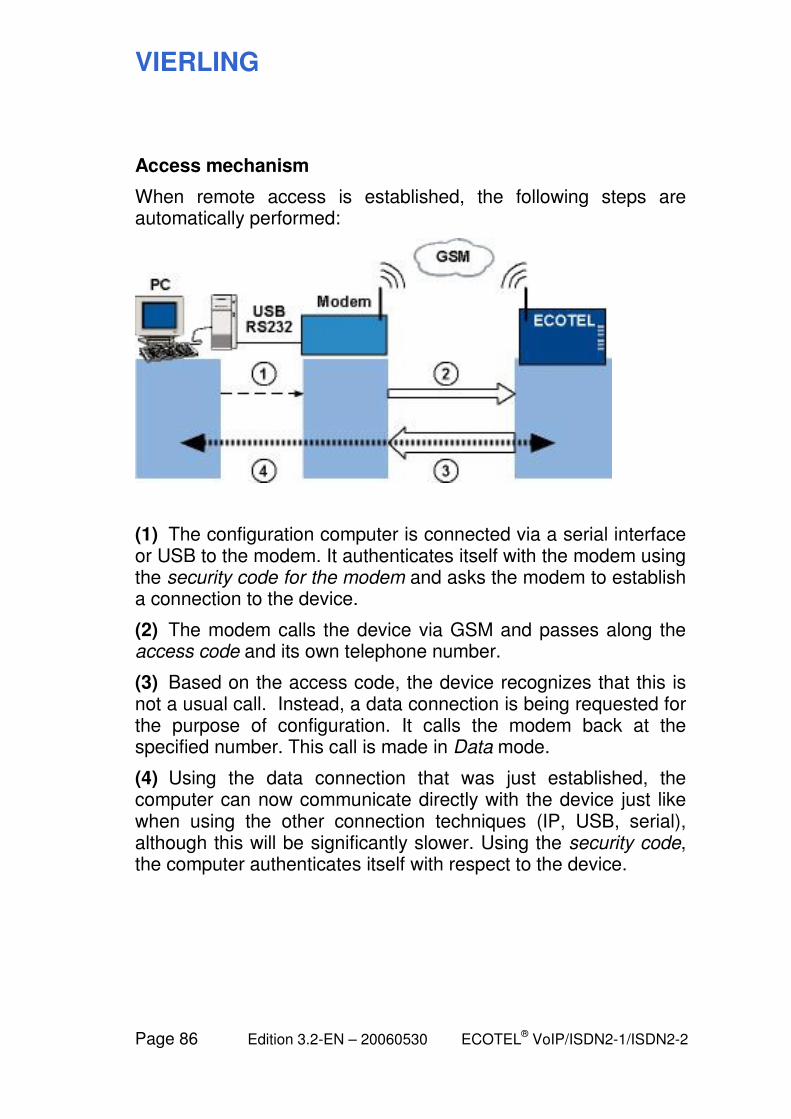
VIERLING
Page 86 Edition 3.2-EN – 20060530 ECOTEL® VoIP/ISDN2-1/ISDN2-2
Access mechanism
When remote access is established, the following steps are automatically performed:
(1) The configuration computer is connected via a serial interface or USB to the modem. It authenticates itself with the modem using the security code for the modem and asks the modem to establish a connection to the device.
(2) The modem calls the device via GSM and passes along the access code and its own telephone number.
(3) Based on the access code, the device recognizes that this is not a usual call. Instead, a data connection is being requested for the purpose of configuration. It calls the modem back at the specified number. This call is made in Data mode.
(4) Using the data connection that was just established, the computer can now communicate directly with the device just like when using the other connection techniques (IP, USB, serial), although this will be significantly slower. Using the security code, the computer authenticates itself with respect to the device.
VIERLING
ECOTEL® VoIP/ISDN2-1/ISDN2-2 Edition 3.2-EN – 20060530 Page 87
4.4 Editing the configuration files
You can manage the configuration files in general using Open – Edit – Close.
New/Readout/Open
Here, there are three possibilities:
You can create an entirely new file. In the Gateway Configuration and Basic Configuration modules, choose File > New or File > Factory Default and select the firmware version for your device (since certain parameters must be properly set in the configuration). In this manner, you can obtain a configuration file with the default values. For the routing table and the VoIP user table, there is no template. Here, you will start with an empty window.
You can read out the corresponding file from ECOTEL® (menu
Transmit > Read from ECOTEL or the corresponding button). Be aware that the file which was previously displayed will be discarded.
You can open a file that is present on your computer (menu File > Open or the corresponding button). This allows you to import configurations that were created elsewhere and modify them according to your needs.
Edit
The file which is currently loaded in the display can be edited by changing the values in the input fields. Or, for the routing table, you can compose the desired entries like you do with a text editor.
Furthermore you can edit the routing table using the Routing Wizard:
6.4.4 The Routing Wizard
In the user table for VoIP, use the Entry: New or Edit buttons to create or edit an entry.
VIERLING
Page 88 Edition 3.2-EN – 20060530 ECOTEL® VoIP/ISDN2-1/ISDN2-2
Save/Download
You can save the edited file on your computer (menu File > Save, File > Save As or by using the corresponding button).
In order to enable the changed settings on ECOTEL®, you need to
transmit the file to it (menu Transmit > Save in ECOTEL or the button Download to ECOTEL).
Warning: As a general rule, you should use the paths which are suggested. If you do not, be sure you are familiar with the basic concepts of the database.
On the actual device, the configuration files must always be named as follows: ECOTEL.UPB, ECOTEL.BSB, USER.TXT and RTBL.TXT. For downloads, these names are always used.
When opening the Gateway Configuration and Basic Configuration modules, the application automatically looks in the database for the file associated with the device (ECOTEL.UPB or ECOTEL.BSB) even if a file with a different name was last edited. We suggest very strongly that you use these names.
VIERLING
ECOTEL® VoIP/ISDN2-1/ISDN2-2 Edition 3.2-EN – 20060530 Page 89
4.5 Generating traces
Traces are detailed information generated by a program during its operation if trace mode is activated.
Traces are normally switched off. However, when problems occur, it can be useful to create and record traces for troubleshooting purposes. This allows you to have a detailed look at what is happening in the device.
If you contact the manufacturer’s support hotline for help with a problem, you might be asked to generate certain traces and send them in. The following sections describe how to activate traces as required and save the recorded data.
Evaluation of the data is the job of the support technician since it requires special expertise that is beyond the scope of this manual.
A brief summary of the most important information can be found here:
4.5.1 Creating traces at a glance
The remaining sections provide more of the relevant details.
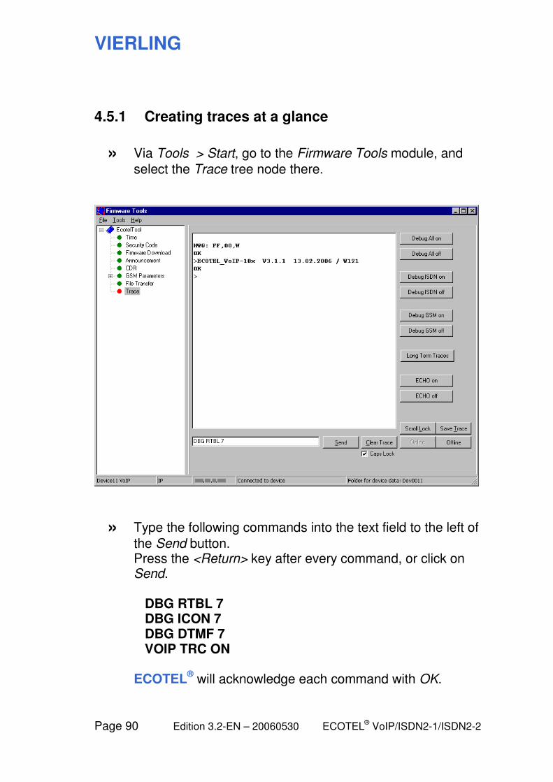
VIERLING
Page 90 Edition 3.2-EN – 20060530 ECOTEL® VoIP/ISDN2-1/ISDN2-2
4.5.1 Creating traces at a glance
» Via Tools > Start, go to the Firmware Tools module, and
select the Trace tree node there.
» Type the following commands into the text field to the left of
the Send button. Press the <Return> key after every command, or click on Send. DBG RTBL 7 DBG ICON 7 DBG DTMF 7 VOIP TRC ON ECOTEL
® will acknowledge each command with OK.

VIERLING
ECOTEL® VoIP/ISDN2-1/ISDN2-2 Edition 3.2-EN – 20060530 Page 91
» If your support technician provides you with further
commands, enter them the same way.
» Now perform the actions (e.g. calls) to be analyzed using
the traces. In the large window, the trace output will appear. Wait until the actions you are interested in have been executed.
» Click on Save Trace.
Select a path and file name and write them down so you can find your trace file later.
» Turn the traces back off by typing the following commands
in order: DBG RTBL 0 DBG ICON 0 DBG DTMF 0 VOIP TRC OFF
» Send an e-mail to
[email protected] and attach the saved file, a brief description of your problem and your ECOTEL
®'s configuration files:
ECOTEL.UPB ECOTEL.BSB RTBL.TXT (routing table); additionally for ECOTEL
®VoIP:
ECOTEL.SMC, USER.TXT (user table).
VIERLING
Page 92 Edition 3.2-EN – 20060530 ECOTEL® VoIP/ISDN2-1/ISDN2-2
4.5.2 Generating traces: Explanation
To activate traces, switch to the Firmware Tools module via Tools > Start and select the Trace tree node.
For information on individual operating elements, see:
6.5.9 Firmware Tools: Trace
Display and input
The large window shows all of messages and trace output from ECOTEL
®.
The text field under this is used to input your commands. Click on the Send button or press the Return key to send the command. ECOTEL
® will confirm each command it receives with an OK
message.
Commands are always in capital letters so we suggest keeping the Caps Lock key activated.
Different trace types
ECOTEL® contains several different software modules that can
generate traces and in some of them, different levels can be activated. You can intentionally activate these trace types using appropriate commands (even multiple levels simultaneously).
The main trace types and the associated commands are described in the following section.
4.5.3 Generating traces: Examples
Note: The more traces you activate, the more information will be generated. If too many traces are activated, the clarity can be impaired along with the performance of your device.
If a support technician asks you to create traces, you will be provided with the necessary commands.
VIERLING
ECOTEL® VoIP/ISDN2-1/ISDN2-2 Edition 3.2-EN – 20060530 Page 93
Starting and stopping traces
Type in the start command for the desired trace type and level and press the Return key.
Tracing should now be activated: For each relevant event in ECOTEL
®, a line will appear in the message window.
When you no longer need tracing, you should make sure that you switch it back off. This is important because it will prevent unnecessary loading of the ECOTEL
® and (most importantly) will
not block access via modem, which is possible only when tracing is switched off. Enter the command used to switch off tracing and press the Return key.
Buttons for standard trace types
To the right of the large display window are some buttons you can use to switch the most common trace types on and off. Each keypress is the same as entering a start (or stop) command.
Direct command entry is less convenient, but it will be required if you want to use newer or less common trace types for which there are not (yet) any buttons.
Saving traces
To save the trace data that is generated, click on the Save button and enter the location for the file in the dialog that appears.
Make a note of the path and file name so you will be able to find the trace file later and send it to the support technician if requested.
Trace files have the extension .TRC. They are plain text files that you can open with any text editor.
If the device is to be monitored over a longer time interval (e.g. over night), we recommend that you activate long-term traces using the button of the same name. ECOTEL
® will then write the
trace output directly to a file. Once this is finished, don’t forget to switch off long-term traces.
VIERLING
Page 94 Edition 3.2-EN – 20060530 ECOTEL® VoIP/ISDN2-1/ISDN2-2
4.5.3 Generating traces: Examples
This section describes some commonly used trace types with the required commands.
Type the commands exactly as shown, including spaces.
Make sure to switch off any traces you enable after you are done using them.
DBG RTBL
Shows how the routing table is implemented in ECOTEL®. The
trace output contains the dialing information that the A subscriber sends to ECOTEL
® and the number that ECOTEL
® dials in the
outgoing direction.
Start with DBG RTBL 7
Stop with DBG RTBL 0 (last character = zero digit)
The parameter 7 represents the highest possible trace level. With 4 you will receive only the most important messages while 0 will end the trace.
DBG LINK
Shows the events that control the call (SETUP, CONNECT, etc.) for each interface (particularly the other interface that is connected to).
Start with DBG LINK[n] 7
Stop with DBG LINK[n] 0 (last character = zero digit)
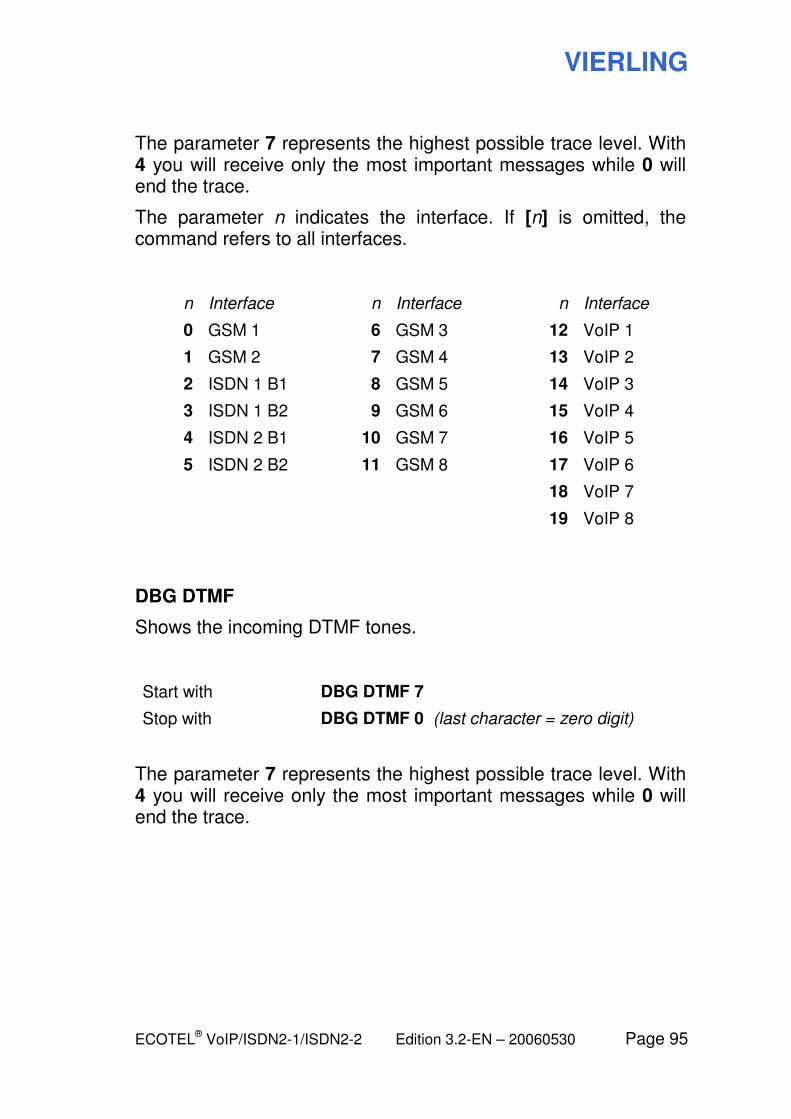
VIERLING
ECOTEL® VoIP/ISDN2-1/ISDN2-2 Edition 3.2-EN – 20060530 Page 95
The parameter 7 represents the highest possible trace level. With 4 you will receive only the most important messages while 0 will end the trace.
The parameter n indicates the interface. If [n] is omitted, the command refers to all interfaces.
n Interface n Interface n Interface
0 GSM 1 6 GSM 3 12 VoIP 1
1 GSM 2 7 GSM 4 13 VoIP 2
2 ISDN 1 B1 8 GSM 5 14 VoIP 3
3 ISDN 1 B2 9 GSM 6 15 VoIP 4
4 ISDN 2 B1 10 GSM 7 16 VoIP 5
5 ISDN 2 B2 11 GSM 8 17 VoIP 6
18 VoIP 7
19 VoIP 8
DBG DTMF
Shows the incoming DTMF tones.
Start with DBG DTMF 7
Stop with DBG DTMF 0 (last character = zero digit)
The parameter 7 represents the highest possible trace level. With 4 you will receive only the most important messages while 0 will end the trace.
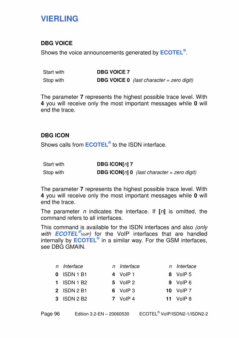
VIERLING
Page 96 Edition 3.2-EN – 20060530 ECOTEL® VoIP/ISDN2-1/ISDN2-2
DBG VOICE
Shows the voice announcements generated by ECOTEL®.
Start with DBG VOICE 7
Stop with DBG VOICE 0 (last character = zero digit)
The parameter 7 represents the highest possible trace level. With 4 you will receive only the most important messages while 0 will end the trace.
DBG ICON
Shows calls from ECOTEL® to the ISDN interface.
Start with DBG ICON[n] 7
Stop with DBG ICON[n] 0 (last character = zero digit)
The parameter 7 represents the highest possible trace level. With 4 you will receive only the most important messages while 0 will end the trace.
The parameter n indicates the interface. If [n] is omitted, the command refers to all interfaces.
This command is available for the ISDN interfaces and also (only with ECOTEL
®VoIP) for the VoIP interfaces that are handled
internally by ECOTEL® in a similar way. For the GSM interfaces,
see DBG GMAIN.
n Interface n Interface n Interface
0 ISDN 1 B1 4 VoIP 1 8 VoIP 5
1 ISDN 1 B2 5 VoIP 2 9 VoIP 6
2 ISDN 2 B1 6 VoIP 3 10 VoIP 7
3 ISDN 2 B2 7 VoIP 4 11 VoIP 8
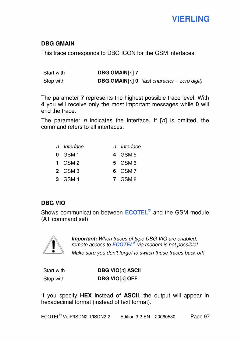
VIERLING
ECOTEL® VoIP/ISDN2-1/ISDN2-2 Edition 3.2-EN – 20060530 Page 97
DBG GMAIN
This trace corresponds to DBG ICON for the GSM interfaces.
Start with DBG GMAIN[n] 7
Stop with DBG GMAIN[n] 0 (last character = zero digit)
The parameter 7 represents the highest possible trace level. With 4 you will receive only the most important messages while 0 will end the trace.
The parameter n indicates the interface. If [n] is omitted, the command refers to all interfaces.
n Interface n Interface
0 GSM 1 4 GSM 5
1 GSM 2 5 GSM 6
2 GSM 3 6 GSM 7
3 GSM 4 7 GSM 8
DBG VIO
Shows communication between ECOTEL® and the GSM module
(AT command set).
Important: When traces of type DBG VIO are enabled, remote access to ECOTEL
® via modem is not possible!
Make sure you don’t forget to switch these traces back off!
Start with DBG VIO[n] ASCII
Stop with DBG VIO[n] OFF
If you specify HEX instead of ASCII, the output will appear in hexadecimal format (instead of text format).
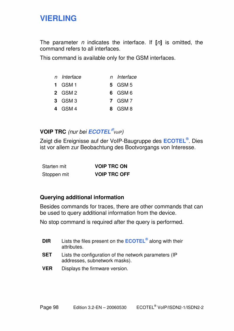
VIERLING
Page 98 Edition 3.2-EN – 20060530 ECOTEL® VoIP/ISDN2-1/ISDN2-2
The parameter n indicates the interface. If [n] is omitted, the command refers to all interfaces.
This command is available only for the GSM interfaces.
n Interface n Interface
1 GSM 1 5 GSM 5
2 GSM 2 6 GSM 6
3 GSM 3 7 GSM 7
4 GSM 4 8 GSM 8
VOIP TRC (nur bei ECOTEL®
VoIP)
Zeigt die Ereignisse auf der VoIP-Baugruppe des ECOTEL®. Dies
ist vor allem zur Beobachtung des Bootvorgangs von Interesse.
Starten mit VOIP TRC ON
Stoppen mit VOIP TRC OFF
Querying additional information
Besides commands for traces, there are other commands that can be used to query additional information from the device.
No stop command is required after the query is performed.
DIR Lists the files present on the ECOTEL® along with their
attributes.
SET Lists the configuration of the network parameters (IP addresses, subnetwork masks).
VER Displays the firmware version.
VIERLING
ECOTEL® VoIP/ISDN2-1/ISDN2-2 Edition 3.2-EN – 20060530 Page 99
5 Introduction to the routing table

VIERLING
Page 100 Edition 3.2-EN – 20060530 ECOTEL® VoIP/ISDN2-1/ISDN2-2
5.1 Overview: Controlling the routing behavior of ECOTEL
To a certain extent, the routing table represents the heart of the ECOTEL
® configuration. Here, you determine how the device
handles incoming calls.
The actual routing table is a text file with lines containing the individual instructions. Using a special syntax, users can define these instructions as required. This is the basis for a wide variety of applications.
Content of the routing table
Each entry in the routing table consists of the following three parts:
Condition / Call type / Destination
Any call which meets the condition is connected to the specified destination.
The following are some possible conditions: The dialed destination number (or parts thereof); the originating number (or parts thereof); the interface via which the call is received; the MSN at which ECOTEL
® was dialed. You can also combine several
different conditions to form a condition for an entry.
Besides the “normal call” call type, there are call types for which ECOTEL
® first calls back the caller before it connects him to the
destination. This means that the charges are incurred by ECOTEL
® and not by the caller. With another call type, it is
possible to block unwanted calls; here, there is no destination. Management connections represent a special case in which ECOTEL
® is the actual destination. This is used for configuration
purposes.
The desired interface must be specified in the destination, meaning at least the type (ISDN, GSM, VoIP) and if desired, the actual interface (BRI1, BRI2) or even a specific ISDN B channel. The destination number which was dialed can be used
VIERLING
ECOTEL® VoIP/ISDN2-1/ISDN2-2 Edition 3.2-EN – 20060530 Page 101
unchanged, parts of it can be changed, or it can be replaced by another number.
More information
First steps to create a new routing table are described here:
5.3 Strategy for the routing table
For a comprehensive reference to syntax elements, see:
6.4.3 The routing syntax
The Routing Wizard can be used to edit the routing table more conveniently:
6.4.4 The Routing Wizard
The examples in this section of the manual illustrating the organization of routing entries refer to this sample application:
3.2.6 Connection as a LCR in PTP mode
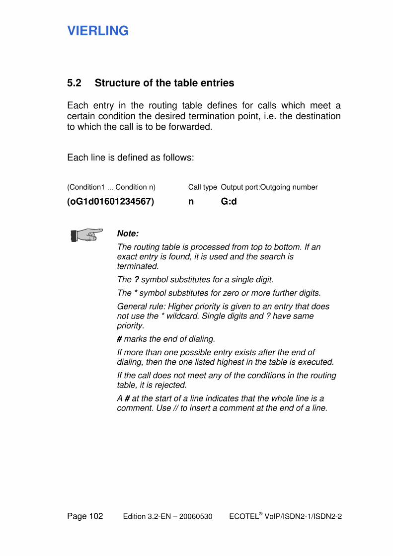
VIERLING
Page 102 Edition 3.2-EN – 20060530 ECOTEL® VoIP/ISDN2-1/ISDN2-2
5.2 Structure of the table entries
Each entry in the routing table defines for calls which meet a certain condition the desired termination point, i.e. the destination to which the call is to be forwarded.
Each line is defined as follows:
(Condition1 ... Condition n) Call type Output port:Outgoing number
(oG1d01601234567) n G:d
Note:
The routing table is processed from top to bottom. If an exact entry is found, it is used and the search is terminated.
The ? symbol substitutes for a single digit.
The * symbol substitutes for zero or more further digits.
General rule: Higher priority is given to an entry that does not use the * wildcard. Single digits and ? have same priority.
# marks the end of dialing.
If more than one possible entry exists after the end of dialing, then the one listed highest in the table is executed.
If the call does not meet any of the conditions in the routing table, it is rejected.
A # at the start of a line indicates that the whole line is a comment. Use // to insert a comment at the end of a line.
VIERLING
ECOTEL® VoIP/ISDN2-1/ISDN2-2 Edition 3.2-EN – 20060530 Page 103
5.3 Strategy for the routing table
We recommend the following basic procedure for creating the routing table:
Basic entries
For each interface which is used (V, I1, I2, G, etc.), create an entry which covers all of the calls arriving from there and routes them with an unmodified destination number to the desired interface:
(oVd*#) n W:d (oI1d*#) n X:d (oI2d*#) n Y:d (oGd*#) n Z:d
Here, the wildcards W, X, Y, Z stand for interface names such as V, I1, I2, G and so on.
The GSM interfaces can usually be grouped together, while the ISDN interfaces are generally used differently (e.g. I1 is connected to the fixed network, I2 to the PBX).
For the VoIP interface, you can (or must) specify for outgoing calls whether they are to be handled via one of the configured SIP outbounds 1 to 8 (port name V1, V2, ... in the routing entry) or whether they should go to one of the locally managed users (port name V). For incoming calls, there is only the common port name V. This means that routing cannot distinguish between incoming VoIP ports.
Information about how to create basic entries can be found under the connection types:
3.2 ISDN interface: Selecting the ISDN connection type 3.3 VoIP interface: Sample applications
VIERLING
Page 104 Edition 3.2-EN – 20060530 ECOTEL® VoIP/ISDN2-1/ISDN2-2
Special cases
Next, insert the desired special cases and exceptions before the relevant basic entry, e.g.:
(oVd*#) n I2:d (oI1d*#) n I2:d (oI2d0160*#) n G:d (oI2d*#) n I1:d (oGd*#) n I2:d
For calls which arrive via I2, the following distinction is made: If the destination number begins with 0160..., the special entry is found first and the call is routed to GSM. In all other cases, the basic entry applies and the call is routed to I1.
For calls via the other interfaces, the basic entry applies.
In this manner, you can gradually refine your routing tables by inserting additional exceptions. Make certain that in each case there is an entry for all of the “remaining” cases since a call will be rejected if there is no relevant entry.
VIERLING
ECOTEL® VoIP/ISDN2-1/ISDN2-2 Edition 3.2-EN – 20060530 Page 105
5.4 Outgoing calls
The routing can be made dependent on the destination number which the caller chooses.
A specific interface for termination can be specified by using the originating telephone number.
However, it is also possible to specify a number which is different than the original telephone number for termination. In this manner, it is possible to define speed dialing numbers, for example.
The important thing is that ECOTEL® must be able to recognize
the end of a sequence of dialing digits. A fixed definition for the number of digits can be used, or the end of dialing indicator # can be used.
VIERLING
Page 106 Edition 3.2-EN – 20060530 ECOTEL® VoIP/ISDN2-1/ISDN2-2
5.4.1 Calls to an arbitrary mobile network connection
Example 1:
Dial the phone number 01601234567 in the GSM network.
Entry in the routing table:
(d01601234567) n G:d
Note: The d character signifies that the number sequence having been dialed is to be utilized as the destination phone number.
Example 2:
Dial the phone number 0160<and exactly 7 additional digits> in the GSM network.
Entry in the routing table:
(d0160???????) n G:d
Note: The ? wildcard indicates that a single arbitrary dialing digit follows.
VIERLING
ECOTEL® VoIP/ISDN2-1/ISDN2-2 Edition 3.2-EN – 20060530 Page 107
Example 3:
Dial the phone number 0160<and exactly 4 additional digits>123 in the GSM network.
Entry in the routing table:
(d0160????123) n G:d
Example 4:
Dial the phone number 0160<and at least 4 additional digits> in the GSM network.
Entry in the routing table:
(d0160????*#) n G:d
Note: If phone numbers have different lengths, then the asterisks (*) wildcard can be used to signify either that no dialing digits follow or that an arbitrary number of dialing digits follow. For such entries, the end of dialing symbol (#) is required since the actual length of the phone number is lost in the process. If the dialing procedure is terminated with #, then it will be immediately executed. Otherwise, dialing will only be executed after expiration of the dialing timeout. This timeout can be configured in the Gateway Configuration module under Properties.
Example 5:
When dialing the phone number 0160<and an arbitrary number of additional digits>, dial the fixed phone number 01601234567 in the GSM network.
Entry in the routing table:
(d0160*#) n G:01601234567
VIERLING
Page 108 Edition 3.2-EN – 20060530 ECOTEL® VoIP/ISDN2-1/ISDN2-2
Example 6:
When using speed dialer 10, dial the phone number 01601111111 in the GSM network; for speed dialer 12, dial the phone number 01601234567, and for speed dialer 123, dial the phone number 01607654321.
Entry in the routing table:
(d10) n G:01601111111 (d12#) n G:01601234567 (d123) n G:01607654321
Note: The ambiguity of speed dialing entries must be taken into consideration. The general rule is: The shortest entry will be used if other entries exist having identical starting sequences. Accordingly, such entries require the number symbol (#) to indicate the end of the number being dialed.
Example 7:
When dialing the phone number 01604, 01605, 01606 or 01609<and an arbitrary number of additional digits>, module 1 should be used to connect to the GSM network. For all other phone numbers starting with 0160<and an arbitrary number of additional digits>, module 2 should be used to connect to the GSM network.
Entry in the routing table:
(d0160[4-69]*#) n G1:d (d0160*#) n G2:d
Note: Using entries in "[ ]", several permissible digits can be specified at a specific position. This can be used to keep the routing table short in case you need to cover numbering variations.
VIERLING
ECOTEL® VoIP/ISDN2-1/ISDN2-2 Edition 3.2-EN – 20060530 Page 109
Example 8: Invalid entry
Dial the phone number 0160<and an arbitrary number of additional digits>11 in the GSM network.
Entry in the routing table:
(d0160*11#) n G:d
Error: The * wildcard may not be used within a routing entry.
VIERLING
Page 110 Edition 3.2-EN – 20060530 ECOTEL® VoIP/ISDN2-1/ISDN2-2
5.4.2 Calls to an arbitrary fixed network connection
Example 1:
Dial the phone number 0999123456 in the fixed network.
Entry in the routing table:
(d0999123456) n I1:d
Example 2:
Dial the phone number 0999<and exactly 6 additional digits> in the fixed network.
Dial the phone number 0888<and exactly 3 additional digits>23 in the fixed network.
Entry in the routing table:
(d0999??????) n I1:d (d0888???23) n I1:d
Example 3:
Dial the phone number 0999<and at least 3 additional digits> in the fixed network.
Entry in the routing table:
(d0999???*#) n I1:d
Example 4:
When dialing 0999<and an arbitrary number of additional digits>, dial the phone number 1234567 in the fixed network.
Entry in the routing table:
(d0999*#) n I1:1234567
VIERLING
ECOTEL® VoIP/ISDN2-1/ISDN2-2 Edition 3.2-EN – 20060530 Page 111
Example 5:
When using speed dialer 10, dial the phone number 1111111 in the fixed network; for speed dialer 11, dial the phone number 222222 in the fixed network; and for 112, dial the emergency number 112 in the fixed network.
Entry in the routing table:
(d10) n I1:111111 (d11#) n I1:222222 (d112) n I1:112
Example 6: Invalid entry
When dialing 0999<and an arbitrary number of additional digits>11, dial the selected phone number in the fixed network.
Entry in the routing table:
(d0999*11#) n I1:d
Error: The * wildcard may not be used within a routing entry.
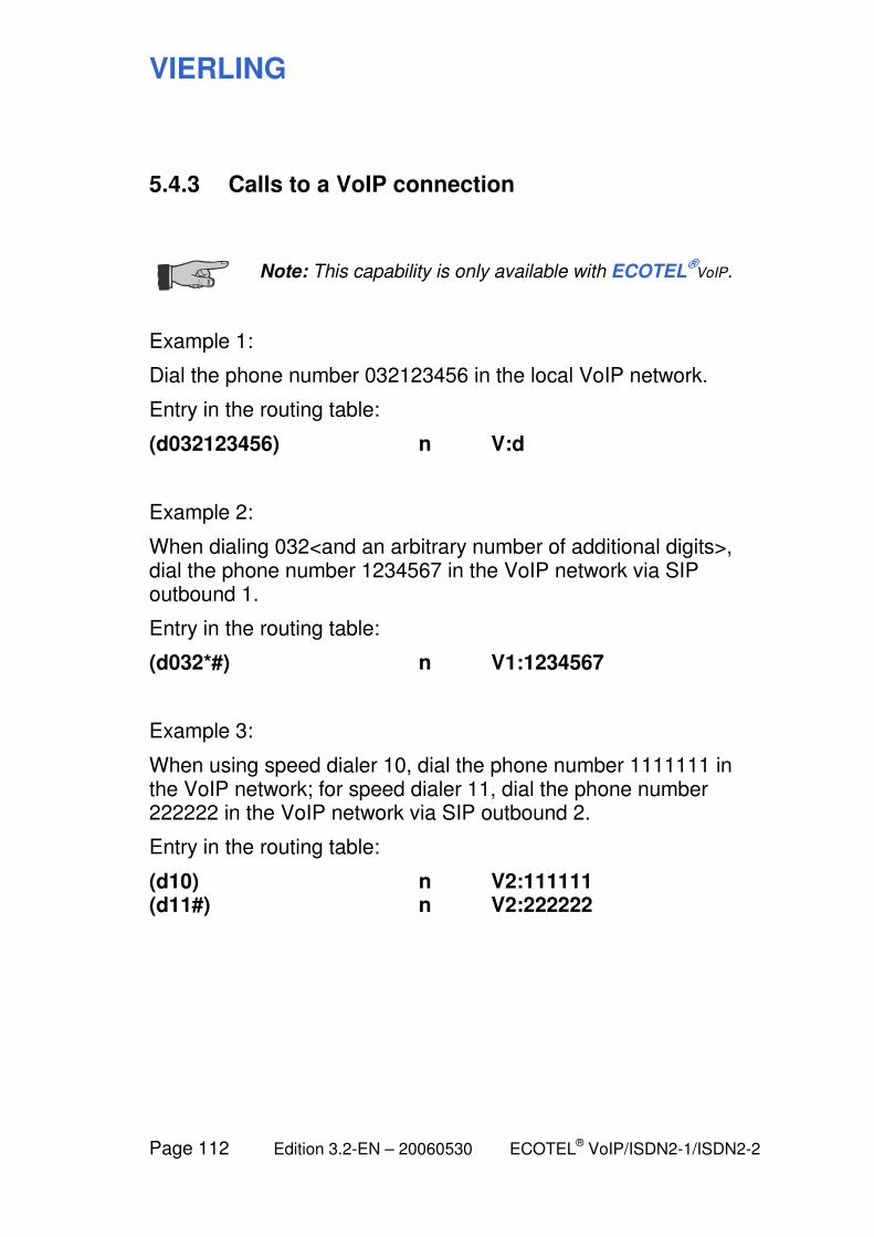
VIERLING
Page 112 Edition 3.2-EN – 20060530 ECOTEL® VoIP/ISDN2-1/ISDN2-2
5.4.3 Calls to a VoIP connection
Note: This capability is only available with ECOTEL
®VoIP.
Example 1:
Dial the phone number 032123456 in the local VoIP network.
Entry in the routing table:
(d032123456) n V:d
Example 2:
When dialing 032<and an arbitrary number of additional digits>, dial the phone number 1234567 in the VoIP network via SIP outbound 1.
Entry in the routing table:
(d032*#) n V1:1234567
Example 3:
When using speed dialer 10, dial the phone number 1111111 in the VoIP network; for speed dialer 11, dial the phone number 222222 in the VoIP network via SIP outbound 2.
Entry in the routing table:
(d10) n V2:111111 (d11#) n V2:222222

VIERLING
ECOTEL® VoIP/ISDN2-1/ISDN2-2 Edition 3.2-EN – 20060530 Page 113
5.4.4 Calls to an arbitrary extension
Example 1:
Dial the phone number for extension 1234.
Entry in the routing table:
(d1234) n I2:d
Example 2:
Dial the phone number for extension 1<and exactly 3 additional digits>.
Entry in the routing table:
(d1???) n I2:d
Example 3:
Dial the phone number for extension 2<and at least 2 additional digits>.
Entry in the routing table:
(d2??*#) n I2:d
Example 4:
When dialing 0<and an arbitrary number of additional digits>, dial the extension 4567.
Entry in the routing table:
(d0*#) n I2:4567
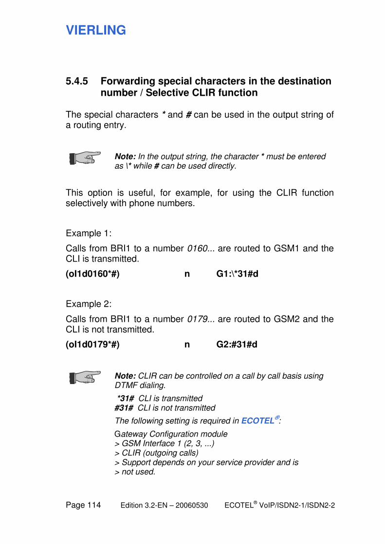
VIERLING
Page 114 Edition 3.2-EN – 20060530 ECOTEL® VoIP/ISDN2-1/ISDN2-2
5.4.5 Forwarding special characters in the destination number / Selective CLIR function
The special characters * and # can be used in the output string of a routing entry.
Note: In the output string, the character * must be entered as \* while # can be used directly.
This option is useful, for example, for using the CLIR function selectively with phone numbers.
Example 1:
Calls from BRI1 to a number 0160... are routed to GSM1 and the CLI is transmitted.
(oI1d0160*#) n G1:\*31#d
Example 2:
Calls from BRI1 to a number 0179... are routed to GSM2 and the CLI is not transmitted.
(oI1d0179*#) n G2:#31#d
Note: CLIR can be controlled on a call by call basis using DTMF dialing.
*31# CLI is transmitted #31# CLI is not transmitted
The following setting is required in ECOTEL®:
Gateway Configuration module > GSM Interface 1 (2, 3, ...) > CLIR (outgoing calls) > Support depends on your service provider and is > not used.
VIERLING
ECOTEL® VoIP/ISDN2-1/ISDN2-2 Edition 3.2-EN – 20060530 Page 115
5.5 Incoming calls
The routing can be also made a function of the number of the caller.
It is also possible to use different MSNs of the ECOTEL® in order
to direct calls to different destinations. This allows the actual caller to control the routing behavior by choosing the appropriate MSN.
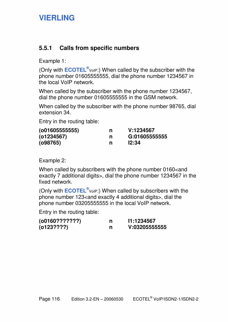
VIERLING
Page 116 Edition 3.2-EN – 20060530 ECOTEL® VoIP/ISDN2-1/ISDN2-2
5.5.1 Calls from specific numbers
Example 1:
(Only with ECOTEL®
VoIP:) When called by the subscriber with the phone number 01605555555, dial the phone number 1234567 in the local VoIP network.
When called by the subscriber with the phone number 1234567, dial the phone number 01605555555 in the GSM network.
When called by the subscriber with the phone number 98765, dial extension 34.
Entry in the routing table:
(o01605555555) n V:1234567 (o1234567) n G:01605555555 (o98765) n I2:34
Example 2:
When called by subscribers with the phone number 0160<and exactly 7 additional digits>, dial the phone number 1234567 in the fixed network.
(Only with ECOTEL®
VoIP:) When called by subscribers with the phone number 123<and exactly 4 additional digits>, dial the phone number 03205555555 in the local VoIP network.
Entry in the routing table:
(o0160???????) n I1:1234567 (o123????) n V:03205555555
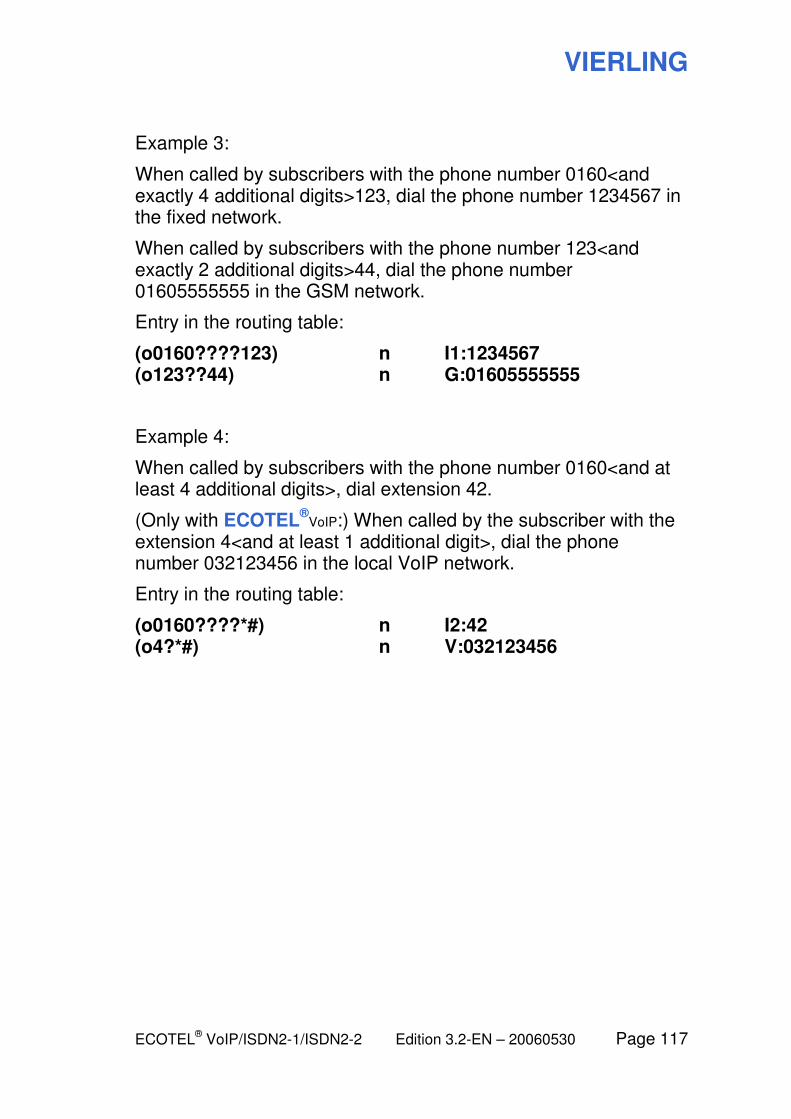
VIERLING
ECOTEL® VoIP/ISDN2-1/ISDN2-2 Edition 3.2-EN – 20060530 Page 117
Example 3:
When called by subscribers with the phone number 0160<and exactly 4 additional digits>123, dial the phone number 1234567 in the fixed network.
When called by subscribers with the phone number 123<and exactly 2 additional digits>44, dial the phone number 01605555555 in the GSM network.
Entry in the routing table:
(o0160????123) n I1:1234567 (o123??44) n G:01605555555
Example 4:
When called by subscribers with the phone number 0160<and at least 4 additional digits>, dial extension 42.
(Only with ECOTEL®
VoIP:) When called by the subscriber with the extension 4<and at least 1 additional digit>, dial the phone number 032123456 in the local VoIP network.
Entry in the routing table:
(o0160????*#) n I2:42 (o4?*#) n V:032123456

VIERLING
Page 118 Edition 3.2-EN – 20060530 ECOTEL® VoIP/ISDN2-1/ISDN2-2
Example 5: Invalid entry
When called by subscribers with the phone number 0160<and an arbitrary number of additional digits>11, dial the fixed phone number 1234567 in the fixed network.
When called by subscribers with the phone number 123, dial a phone number which is not present in the GSM network.
Entry in the routing table:
(o0160*11) n I1:1234567 (o123) n G:d
Error: The * wildcard may not be used within a routing entry.
Error: The d character may not be used without specifying a destination phone number.
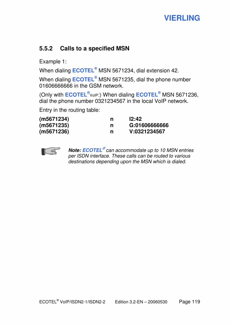
VIERLING
ECOTEL® VoIP/ISDN2-1/ISDN2-2 Edition 3.2-EN – 20060530 Page 119
5.5.2 Calls to a specified MSN
Example 1:
When dialing ECOTEL® MSN 5671234, dial extension 42.
When dialing ECOTEL® MSN 5671235, dial the phone number
01606666666 in the GSM network.
(Only with ECOTEL®
VoIP:) When dialing ECOTEL® MSN 5671236,
dial the phone number 0321234567 in the local VoIP network.
Entry in the routing table:
(m5671234) n I2:42 (m5671235) n G:01606666666 (m5671236) n V:0321234567
Note: ECOTEL
® can accommodate up to 10 MSN entries
per ISDN interface. These calls can be routed to various destinations depending upon the MSN which is dialed.
VIERLING
Page 120 Edition 3.2-EN – 20060530 ECOTEL® VoIP/ISDN2-1/ISDN2-2
5.6 Port-specific calls
The routing behavior can also be made a function of the interface (= port) on which the call arrives. The outgoing port can also be specified. With the ISDN interfaces, it is also possible to distinguish between the B channels.

VIERLING
ECOTEL® VoIP/ISDN2-1/ISDN2-2 Edition 3.2-EN – 20060530 Page 121
5.6.1 Routing based on the interface
Example 1:
When called by the subscriber via any mobile radio module, dial the phone number 1234567 in the fixed network.
When called by a fixed network subscriber, dial the phone number 01605555555 in the GSM network using any mobile radio module.
When called by a PBX subscriber, dial the phone number 01606666666 in the GSM network using mobile radio module 2.
(Only with ECOTEL®
VoIP:) When called by a VoIP network subscriber, dial the phone number 01607777777 in the GSM network using any mobile radio module.
Entry in the routing table:
(oG) n I1:1234567 (oI1) n G:01605555555 (oI2) n G2:01606666666 (oV) n G:01607777777
Example 2:
When called by subscribers using any mobile radio module with the phone number 0160<and exactly 7 additional digits>, dial the fixed phone number 1234567 in the fixed network.
Entry in the routing table:
(oG:0160???????) n I1:1234567
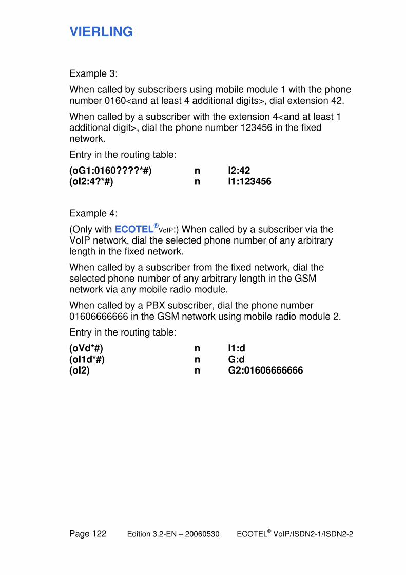
VIERLING
Page 122 Edition 3.2-EN – 20060530 ECOTEL® VoIP/ISDN2-1/ISDN2-2
Example 3:
When called by subscribers using mobile module 1 with the phone number 0160<and at least 4 additional digits>, dial extension 42.
When called by a subscriber with the extension 4<and at least 1 additional digit>, dial the phone number 123456 in the fixed network.
Entry in the routing table:
(oG1:0160????*#) n I2:42 (oI2:4?*#) n I1:123456
Example 4:
(Only with ECOTEL®
VoIP:) When called by a subscriber via the VoIP network, dial the selected phone number of any arbitrary length in the fixed network.
When called by a subscriber from the fixed network, dial the selected phone number of any arbitrary length in the GSM network via any mobile radio module.
When called by a PBX subscriber, dial the phone number 01606666666 in the GSM network using mobile radio module 2.
Entry in the routing table:
(oVd*#) n I1:d (oI1d*#) n G:d (oI2) n G2:01606666666
VIERLING
ECOTEL® VoIP/ISDN2-1/ISDN2-2 Edition 3.2-EN – 20060530 Page 123
5.6.2 B-channel routing
By indicating the input port in the condition as well as the destination port, it is possible to distinguish the ISDN B channels.
Example 1:
Calls from B channel 1 of interface BRI1 are to be routed to GSM interface 1.
Calls from B channel 2 of interface BRI1 are to be routed to GSM interface 2.
Entry in the routing table:
(oI11d*#) n G1:d (oI12d*#) n G2:d
Example 2:
Calls from GSM interface 1 are to be routed to B channel 1 of interface BRI2.
Calls from GSM interface 2 are to be routed to B channel 2 of interface BRI2.
Entry in the routing table:
(oG1d*#) n I21:d (oG2d*#) n I22:d
VIERLING
Page 124 Edition 3.2-EN – 20060530 ECOTEL® VoIP/ISDN2-1/ISDN2-2
5.7 Blocking calls
Another possible routing behavior involves rejecting the call instead of forwarding it to a destination. Of course, in this case the routing entry will not contain a destination.
5.7.1 Blocking calls from specific originating numbers
Example 1:
Dialing in from the fixed network is blocked for all subscribers.
Dialing in from the GSM network is blocked for subscribers with phone numbers 0160<and any arbitrary number of additional digits>.
Entry in the routing table:
(oI1) b (oG:0160*) b
5.7.2 Blocking calls to specific destination numbers
Example 1:
Dialing 0190<and any number of additional digits> is blocked for all subscribers.
Dialing 0160<and any number of additional digits> is blocked for all extension subscribers.
Dialing international subscribers starting with 00<and any number of additional digits> is blocked for all GSM network subscribers.
Entry in the routing table:
(d0190*) b (oI2d0160*) b (oGd00*) b
VIERLING
ECOTEL® VoIP/ISDN2-1/ISDN2-2 Edition 3.2-EN – 20060530 Page 125
5.8 Date- and time-dependent routing
The validity of routing entries can be limited in terms of time. The condition must be extended as follows:
Example 1:
The first routing entry is valid only from Monday to Wednesday.
The second routing entry is valid on Monday and also from Friday to Sunday.
Entry in the routing table:
(...w1-3) ... ... (...w15-7) ... ...
Note: The w character can be used to indicate that the routing entry is to be valid only on certain days of the week.
Days of the week are entered as numbers: 1=Monday … 7=Sunday
VIERLING
Page 126 Edition 3.2-EN – 20060530 ECOTEL® VoIP/ISDN2-1/ISDN2-2
Example 2:
The first routing entry is valid from December 31, 2004 to January 7, 2005.
The second routing entry is valid each year on December 31.
The third routing entry is valid from January 1, 2004 to September 30, 2004.
Entry in the routing table:
(...c04/12/31-05/01/07) ... ... (...c*/12/31-*/12/31) ... ... (...c04/01/01-04/0?/30) ... ...
Note: The c character can be used to indicate that the routing entry is valid only on certain days of the year.
The date format is yy/mm/dd.
You can also use the * and ? wildcards.
Example 3:
The first routing entry is valid daily from 00:00:00 to 12:00:00.
The second routing entry is valid daily from 00:00:00 to 09:00:00.
Entry in the routing table:
(...t00:00:00-12:00:00) ... ... (...t00:00-9:00) ... ...
Note: The t character can be used to indicate that the routing entry is to be valid only at certain times of day.
The time of day format is hh:mm:ss.
Seconds and leading zeros may be omitted.
You can also use the * and ? wildcards.
VIERLING
ECOTEL® VoIP/ISDN2-1/ISDN2-2 Edition 3.2-EN – 20060530 Page 127
Example 4:
The routing entry is valid for calls which arrive from interface BRI1 and which have as their destination the speed dial number 78 but only Monday through Friday or Sunday, and only from March 1 to December 31, 2004, in each case between midnight and noon.
Entry in the routing table:
(oI1d78w1-57c04/03/01-04/12/31t00:00-12:00) ... ...
Note: You can combine the various types of conditions (origin, destination, time, etc.) in various ways. An AND operation is used, i.e. each and every condition must be fulfilled for routing based on the entry to be performed.
VIERLING
Page 128 Edition 3.2-EN – 20060530 ECOTEL® VoIP/ISDN2-1/ISDN2-2
5.9 Automatic callbacks
Sometimes it is desirable to exchange the roles of the calling party and the called party so that the called party can bear the cost of the call, for example.
For this purpose, ECOTEL®
can, instead of immediately forwarding a call to a destination, first establish a connection back to the caller and then connect the caller to the actual destination via this connection.
A callback is made when the original call fulfills a condition which is defined in the routing table as a callback trigger. This can be the dialed destination number (dialing callback) or the originating number from which the call comes (non-dialing callback).
First, the original call must be terminated either automatically by ECOTEL
® (with disconnect, meaning: by ECOTEL
®) or by the
caller so that he himself can control the disconnect time point (without disconnect).
After a delay of 10 seconds, ECOTEL® initiates the callback to the
number provided in the routing table (for example, you can indicate that the calling number is to be used). Once the callback has been established, the caller can dial the actual desired destination number (e.g. an extension). ECOTEL
® then connects
the caller to this number.
Besides lower rates, this technique is used typically for management connections to ECOTEL
® (the called party must
have a SIM card which is capable of handling data).
VIERLING
ECOTEL® VoIP/ISDN2-1/ISDN2-2 Edition 3.2-EN – 20060530 Page 129
5.9.1 Dialing callback with disconnect
The caller dials ECOTEL® and is connected to ECOTEL
®. He
dials a number which is defined in the routing table as an automatic callback. Then, the connection is disconnected by ECOTEL
®.
In about 10 seconds, ECOTEL® calls back the defined number.
The delay is necessary in order to allow the caller to hang up.
The caller answers the callback and is connected to ECOTEL®.
Any number that is defined in the routing table can now be dialed by the caller.
Example 1:
The caller dials the number 123 and is disconnected immediately. The call is returned over the same port under the number 01601234567.
Entry in the routing table:
(d123) c &:01601234567
Note: The & sign signifies that the same port is to be used for callback.
Example 2:
The caller dials the number 123 and is disconnected immediately. The call is returned using mobile radio module 2 in the GSM network under the number 01601234567.
Entry in the routing table:
(d123) c G2:01601234567
VIERLING
Page 130 Edition 3.2-EN – 20060530 ECOTEL® VoIP/ISDN2-1/ISDN2-2
Example 3: Invalid entry
The caller dials the number 123 and is disconnected immediately. The call is returned in the GSM network over mobile radio module 2 under a phone number which is not available.
Entry in the routing table:
(d123) c G:d
Note: A valid callback number must be specified in ECOTEL
®.
VIERLING
ECOTEL® VoIP/ISDN2-1/ISDN2-2 Edition 3.2-EN – 20060530 Page 131
5.9.2 Dialing callback without disconnect
The caller dials ECOTEL® and is connected to ECOTEL
®. He
dials a number which is defined in the routing table as an automatic callback. After that, the caller hangs up.
In about 10 seconds, ECOTEL® calls back the defined number.
The delay is necessary in order to allow the caller to hang up.
The caller answers the callback and is connected to ECOTEL®.
Any number that is defined in the routing table can now be dialed by the caller.
Example 1:
The caller dials the number 123, disconnects and is called back over the same port under the number 01601234567.
Entry in the routing table:
(d123) p &:01601234567
Example 2:
The caller dials the number 123, disconnects and is called back in the GSM network using mobile radio module 2 under the number 01601234567.
Entry in the routing table:
(d123) p G2:01601234567
VIERLING
Page 132 Edition 3.2-EN – 20060530 ECOTEL® VoIP/ISDN2-1/ISDN2-2
5.9.3 Non-dialing callback with disconnect
If an immediate callback has been defined for a caller, then ECOTEL
® disconnects immediately so the call never goes
through.
In approximately 10 seconds, ECOTEL® then calls back the
number that is defined in the routing table.
The caller answers the callback and is connected to ECOTEL®.
Any number that is defined in the routing table can now be dialed by the caller.
Example 1:
The caller with the number 01601234567 is immediately disconnected and is called back over the same port.
Entry in the routing table:
(o01601234567) i &:o
Note: The o character indicates that the number of the originating subscriber is to be used as the destination phone number.
Example 2:
Callers with the number 0160<and an arbitrary number of additional digits> are disconnected immediately and a callback is made in the GSM network using mobile radio module 2 under the number 01601234567.
Entry in the routing table:
(o0160*) i G2: 01601234567
Note: The phone number that is calling ECOTEL
® must
not be suppressed (CLIR).
VIERLING
ECOTEL® VoIP/ISDN2-1/ISDN2-2 Edition 3.2-EN – 20060530 Page 133
5.9.4 Non-dialing callback without disconnect
If a non-dialing callback without disconnect is defined for a caller, then the caller hears the ring tone until he hangs up and the call never goes through. In approximately 10 seconds, ECOTEL
® then
calls back the number that is defined in the routing table.
The caller answers the callback and is connected to ECOTEL®.
Any number that is defined in the routing table can now be dialed by the caller.
Example 1:
The caller with the number 01601234567 is called back over the same port as soon as he disconnects the call.
Entry in the routing table:
(o01601234567) d &:o
Example 2:
As soon as they disconnect the call, callers with the number 0160<and any number of additional digits> are called back in the GSM network over mobile radio module 2.
Entry in the routing table:
(o0160*) d G2:o
Note: The phone number that is calling ECOTEL
® must
not be suppressed (CLIR).
VIERLING
Page 134 Edition 3.2-EN – 20060530 ECOTEL® VoIP/ISDN2-1/ISDN2-2
5.10 Remote configuration via GSM
For remote configuration via GSM, data calls must be established between the calling and called devices. The called device needs a SIM card which is capable of handling data.
If it is certain that the device to be configured has such a card, the management call can be made directly. Otherwise, a callback technique is needed for access from a device that has data capabilities.
Example 1:
The caller with the number 01601234567 directly establishes a remote configuration call.
Entry in the routing table:
(o01601234567) n M
Example 2:
The caller with the number 01601234567 is disconnected immediately and a remote configuration call is set up using mobile radio module 2 under the number 01602222222.
Entry in the routing table:
(o01601234567) im G2:01602222222
Example 3:
The caller with the number 01601234567 dials the number 5555, is disconnected immediately and a remote configuration call is made using the same radio module to the number 01601234567.
Entry in the routing table:
(oG:01601234567d5555) cm &:o
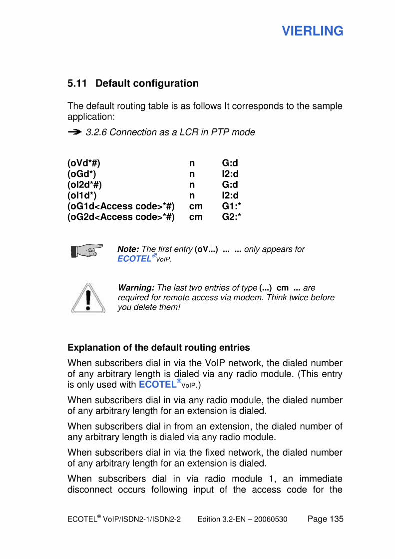
VIERLING
ECOTEL® VoIP/ISDN2-1/ISDN2-2 Edition 3.2-EN – 20060530 Page 135
5.11 Default configuration
The default routing table is as follows It corresponds to the sample application:
3.2.6 Connection as a LCR in PTP mode
(oVd*#) n G:d (oGd*) n I2:d (oI2d*#) n G:d (oI1d*) n I2:d (oG1d<Access code>*#) cm G1:* (oG2d<Access code>*#) cm G2:*
Note: The first entry (oV...) ... ... only appears for ECOTEL
®VoIP.
Warning: The last two entries of type (...) cm ... are required for remote access via modem. Think twice before you delete them!
Explanation of the default routing entries
When subscribers dial in via the VoIP network, the dialed number of any arbitrary length is dialed via any radio module. (This entry is only used with ECOTEL
®VoIP.)
When subscribers dial in via any radio module, the dialed number of any arbitrary length for an extension is dialed.
When subscribers dial in from an extension, the dialed number of any arbitrary length is dialed via any radio module.
When subscribers dial in via the fixed network, the dialed number of any arbitrary length for an extension is dialed.
When subscribers dial in via radio module 1, an immediate disconnect occurs following input of the access code for the
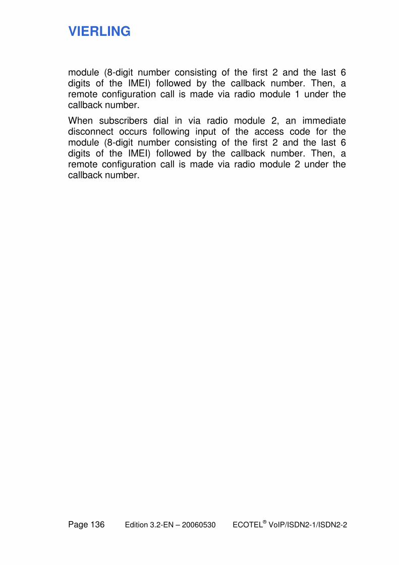
VIERLING
Page 136 Edition 3.2-EN – 20060530 ECOTEL® VoIP/ISDN2-1/ISDN2-2
module (8-digit number consisting of the first 2 and the last 6 digits of the IMEI) followed by the callback number. Then, a remote configuration call is made via radio module 1 under the callback number.
When subscribers dial in via radio module 2, an immediate disconnect occurs following input of the access code for the module (8-digit number consisting of the first 2 and the last 6 digits of the IMEI) followed by the callback number. Then, a remote configuration call is made via radio module 2 under the callback number.
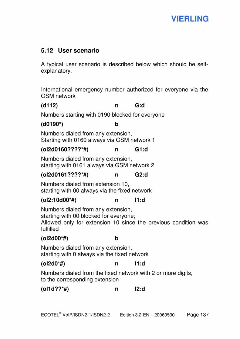
VIERLING
ECOTEL® VoIP/ISDN2-1/ISDN2-2 Edition 3.2-EN – 20060530 Page 137
5.12 User scenario
A typical user scenario is described below which should be self-explanatory.
International emergency number authorized for everyone via the GSM network
(d112) n G:d
Numbers starting with 0190 blocked for everyone
(d0190*) b
Numbers dialed from any extension, Starting with 0160 always via GSM network 1
(oI2d0160????*#) n G1:d
Numbers dialed from any extension, starting with 0161 always via GSM network 2
(oI2d0161????*#) n G2:d
Numbers dialed from extension 10, starting with 00 always via the fixed network
(oI2:10d00*#) n I1:d
Numbers dialed from any extension, starting with 00 blocked for everyone; Allowed only for extension 10 since the previous condition was fulfilled
(oI2d00*#) b
Numbers dialed from any extension, starting with 0 always via the fixed network
(oI2d0*#) n I1:d
Numbers dialed from the fixed network with 2 or more digits, to the corresponding extension
(oI1d??*#) n I2:d
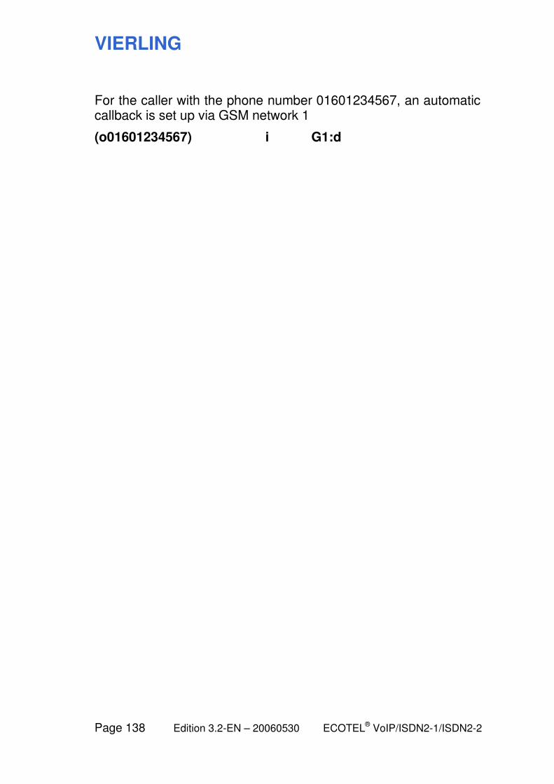
VIERLING
Page 138 Edition 3.2-EN – 20060530 ECOTEL® VoIP/ISDN2-1/ISDN2-2
For the caller with the phone number 01601234567, an automatic callback is set up via GSM network 1
(o01601234567) i G1:d
VIERLING
ECOTEL® VoIP/ISDN2-1/ISDN2-2 Edition 3.2-EN – 20060530 Page 139
6 Reference: Operating elements of the configuration software
VIERLING
Page 140 Edition 3.2-EN – 20060530 ECOTEL® VoIP/ISDN2-1/ISDN2-2
6.1 Overview: The operating elements
This section contains a description of all the operating elements including the menu items, input fields and buttons. The help texts are arranged according to their location in the user interface.
Please be aware that this manual always refers to the latest interface version for each module. Older interface versions can differ from what is described here. For more details about interface versions, see:
8.2 Interpretation of the interface version

VIERLING
ECOTEL® VoIP/ISDN2-1/ISDN2-2 Edition 3.2-EN – 20060530 Page 141
6.2 Service Gear module
The Service Gear module is the first to appear after the program is launched. From there, you can access the other modules.
Using ECOTEL® Service Gear, you can configure and administer
any number of devices of different types. These devices are typically GSM gateways (e. g. ECOTEL
®VoIP, ECOTEL
®ISDN2-1).
You can also manage modems here. These are also devices which are used specifically as an access portal for remote configuration of the “devices” described above.
For each device or modem, a data set is created which describes the device and its configuration interface.
Database
The database uses a directory structure on the computer in which the configuration data sets are stored for all of the devices and modems. The folders are located in the installation directory of the Service Gear software in the EcotelData subdirectory.
Devices/modems
You can create objects to be managed under the devices or modems nodes. For each physical device or modem which is to be managed and configured using the Service Gear software, a device or modem data set must exist in the database.
Devices are the gateways which are used for the actual telephone traffic.
As a general rule, a modem is a gateway which is used to set up a connection to the device to be configured via GSM and transmit its configuration data.
Groups
Devices (but not modems) are grouped together to form a node in the tree. Using a group name, you can group together, e.g. all of the devices at a particular location, for a particular operator or
VIERLING
Page 142 Edition 3.2-EN – 20060530 ECOTEL® VoIP/ISDN2-1/ISDN2-2
having the same properties (SIM cards from the same provider, etc.). Groups can also be arranged hierarchically within other groups.
See also the following sections for information about the operating elements in the main window and the individual dialog windows.
VIERLING
ECOTEL® VoIP/ISDN2-1/ISDN2-2 Edition 3.2-EN – 20060530 Page 143
6.2.1 Service Gear: Main window
Call: Launch using Start > Programs> ECOTEL Service Gear. The Service Gear main window will appear also if you are inside another module and you close it.
The left half of the start window shows all of the relevant devices and modems in a tree structure. You can group together several devices, e.g. devices at a common location or for a common user. Groups can also be arranged hierarchically within other groups. At least one group level must exist.
You can add new devices and modify or delete the data for existing devices. The detailed data for the currently selected device are shown in the right half of the window.
You can open the form for editing the configuration data by clicking on the Properties button.
From Service Gear, you can access the various modules for configuring or administering the currently selected gateway (Tools > Start...).
File
Close Ends the application.
Edit
Add Group Adds a new group below the selected group.
Add Device Add a new device to the selected group. At least one group must exist below the devices node.
Add Modem Adds a new modem.
Cut, Copy, Paste These are the usual Windows functions.
Delete Removes the selected element from the database.
Properties Opens a dialog for editing the properties for the selected element.
VIERLING
Page 144 Edition 3.2-EN – 20060530 ECOTEL® VoIP/ISDN2-1/ISDN2-2
Tools
Debug... Opens an additional Debug Info window with detailed information about the communication between ECOTEL
® and your configuraton
computer.
Language… Allows you to select the language for the user interface.
Start Changes to another module within the ECOTEL configuration software (selected in the submenu)
Note: You can also switch to Gateway Configuration by double-clicking on the desired gateway.
Help
Contents… Opens the content page for the online help.
Info... Shows information about the product version and manufacturer.
Print… Opens a PDF version of the help pages which you can print.
(Tree view) Shows all of devices and modems which are available for a data set.
(Properties window) Shows the properties for the selected element. For more information about the individual fields, see also the description of the Properties dialogs in the following sections.
Properties Opens a dialog for editing the properties.
(Status line) The status line at the bottom edge of the window provides additional information:
(1st field) Reference to the selected tree node
(2nd field) Directory in which the files for the selected device are saved (with the default program installation, this will be C:\Programme\Vierling\ECOTEL_Service_Gear\EcotelData)
Note: Many of these functions can also be accessed using the context menu (right mouse click on an element in the tree view).
VIERLING
ECOTEL® VoIP/ISDN2-1/ISDN2-2 Edition 3.2-EN – 20060530 Page 145
6.2.2 Service Gear: Properties Group
Call: In the Service Gear start window, select a group in the tree view and click on the Properties button.
Group name A user-selectable name for the group.
OK / Cancel Closes the dialog with or without accepting the changes.
VIERLING
Page 146 Edition 3.2-EN – 20060530 ECOTEL® VoIP/ISDN2-1/ISDN2-2
6.2.3 Service Gear: Properties Device
Call: In the Service Gear start window, select a device in the tree view and click on the Properties button.
Before they are stored, the entries are checked to make sure they are within the permissible range of values. If there are any errors, an error message is displayed and the first field with an invalid entry is highlighted.
Device name User-selectable name for the gateway.
Device type Type of device to be managed, e.g. ECOTEL
®VoIP or ECOTEL
®ISDN2-1.
Access via Interface which provides access to the device for configuration purposes.
Note: Usage of the Modem interface has certain peculiarities compared to the other interfaces.
4.3.2 Connecting via modem
Note: The RS232 interface (serial) can be used only with ECOTEL
®ISDN2-1 and the USB
interface not with ECOTEL®
ISDN2-1.
COM port Number of the serial or USB interface of the PC via which the gateway is to be configured. This field is activated only if USB or RS232 is selected as the interface.
Note: The USB interface must be provided with a driver to emulate a COM port. For more information, see
2.2.4 Setting up the USB interface
Select the appropriate COM number here (generally, COM3 or COM4).
IP address IP address of the gateway via which it can be accessed in the LAN by Service Gear for configuration purposes. This field is activated only if IP is selected as the interface.
VIERLING
ECOTEL® VoIP/ISDN2-1/ISDN2-2 Edition 3.2-EN – 20060530 Page 147
Security code A secret code which is sent when accessing the selected configuration interface. Enter the security code for ECOTEL
® into this field.
You can enter or modify the security code stored in ECOTEL
® under Tools > Start >
Firmware Tools > Security Code.
The usage of a security code is optional. If you leave the Security Code field blank, the security code will be queried each time you access the configuration interface of ECOTEL
®.
Call number for remote access
Number which the gateway calls back for remote configuration via GSM. The callback is initiated by a modem call and transfer of the access code for remote access. This field is activated only if Modem is selected as the interface.
Access code The access code for remote access is needed for remote configuration via GSM. Remote configuration of a gateway via GSM is initiated by a call from a modem to the corresponding gateway. An access code for remote access is transmitted to the gateway and the connection is terminated. If this access code for remote access is identical to the access code stored in the gateway, the gateway to be configured begins a callback to the modem so that the configuration data can be exchanged. This field is activated only if Modem is selected as the interface.
Modem Here, you can select a modem stored in the database for remote configuration. This field is activated only if Modem is selected as the interface.
OK / Cancel Closes the dialog with or without accepting the changes.
For additional information about remote access via modem:
4.3.2 Connecting via modem
VIERLING
Page 148 Edition 3.2-EN – 20060530 ECOTEL® VoIP/ISDN2-1/ISDN2-2
6.2.4 Service Gear: Properties Modem
Call: In the Service Gear start window, select a modem in the tree view and click on the Properties button.
Before they are stored, the entries are checked to make sure they are within the permissible range of values. If there are any errors, an error message is displayed and the first field with an invalid entry is highlighted.
Modem name User-selectable name for the modem.
Device type Type of gateway to be managed which will be used as a modem, e.g. ECOTEL
® or
ECOTEL®
ISDN.
Access via Interface which provides access to the modem for configuration purposes.
Note: The RS232 interface (serial) can be used only with ECOTEL
®ISDN2-1 and the USB
interface not with ECOTEL®
ISDN2-1.
COM port Number of the serial or USB interface of the PC via which the modem is to be configured. Activated only if USB or RS232 is selected as the interface.
IP address IP address of the modem via which it can be accessed in the LAN by Service Gear for configuration purposes. This field is activated only if IP is selected as the interface.
Security code A secret code which is used when accessing the selected configuration interface. The usage of a security code is optional.
Callback number (Data mode)
Telephone number at which the modem can be reached by the gateway which calls it back. Data service must be enabled for this number.
OK / Cancel Closes the dialog with or without accepting the changes.
VIERLING
ECOTEL® VoIP/ISDN2-1/ISDN2-2 Edition 3.2-EN – 20060530 Page 149
6.3 Gateway Configuration module
In the Gateway Configuration module, the data relating to the hardware of the selected device are displayed. Depending on the device type, the parameters for each GSM module, each ISDN channel and the VoIP interface might be displayed, for example.
When the software is launched, the most recently saved configu-ration of the device is displayed. If the configuration file for the device has not yet been created, a message is displayed when the Gateway Configuration module is opened along with a request to create a new file.
You can either create a new configuration with the menu item File > New… or read the configuration data from the connected gateway.
When opening a new configuration file, a window opens in which you must select the currently installed firmware configuration in ECOTEL
®. Based on this selection, the corresponding configu-
ration fields are displayed for the functions available in this firmware version. You can then save the configuration. You should use the suggested default directory. As the filename for the configuration file, we recommend that you use ECOTEL.UPB so that the configuration file will be automatically displayed the next time you launch the software.
See also the following sections for information about the operating elements in the main window and the individual configuration pages.
VIERLING
Page 150 Edition 3.2-EN – 20060530 ECOTEL® VoIP/ISDN2-1/ISDN2-2
6.3.1 Gateway Configuration: Main window
Note: The main window is labeled ECOTEL Configuration Software in the title bar. It is distinguished from the main window of the Basic Configuration module by the different tree view.
Call: From any of the modules, using Tools > Start > Gateway Configuration. From the Service Gear module also by double clicking on the corresponding device in the tree view.
Note: If access via the Modem interface is configured for the device, you need to set up a remote access connection before you can call up the Gateway Configuration module.
In the left half of the Gateway Configuration module window, all of the elements to be configured are shown as separate nodes in a tree view. From many of the elements (e.g. GSM, ISDN or VoIP), it is possible to access lower levels which group together special parameters.
In the right half of the window, the parameters are displayed for the selected tree node. Before they are stored, all of your changes are checked to make sure they are within the permissible range of values. Errors are indicated by an exclamation point in a red circle. If you move the mouse pointer over the exclamation point, the expected range of values will be displayed.
(Title bar) Next to the title (ECOTEL Configuration Software), the name of the currently opened configuration file might be displayed (file type *.UPB).
File
Default… Opens a new configuration file with the original values when the device was shipped from the factory. This also corresponds to the menu item File > New.
VIERLING
ECOTEL® VoIP/ISDN2-1/ISDN2-2 Edition 3.2-EN – 20060530 Page 151
New...
Opens a new configuration file with standard values. In a dialog window, you must select the firmware version for the configuration. Depending on the selected version, the relevant parameters are enabled in the user interface and written into the configuration file.
Open…
Displays an Open File dialog so you can search for an existing configuration file. This looks for files of type *.UPB in the folder which is linked to the current device in the Service Gear database.
Save
Saves the configuration file which is currently open.
Save As… Displays the Windows Save File dialog for saving the current configuration file under a different name.
Note: When you open the Gateway Configuration module, the software automatically looks for configuration file named ECOTEL.UPB and opens it if it exists. We recommend that you use this file name since otherwise you will have to manually open the configuration file each time.
Exit Exits the Gateway Configuration module and returns to the Service Gear module.
Transfer
Save in ECOTEL…
Transmits the current configuration file to ECOTEL
®.
Note: The transmitted file is always saved on ECOTEL
® under the name ECOTEL.UPB.
Read from ECOTEL…
Loads the configuration file ECOTEL.UPB from ECOTEL
® and displays the values it contains.
Note: When reading from ECOTEL
®, the
configuration file which is currently open is discarded and the changes are not saved. The file which is read in is unnamed at first; you have to enter a file name when you save it.
VIERLING
Page 152 Edition 3.2-EN – 20060530 ECOTEL® VoIP/ISDN2-1/ISDN2-2
Reboot Causes ECOTEL®
to restart.
Warning: A restart will interrupt all of the telephone connections which are currently running via ECOTEL
®!
Preferences
Preferences…
Opens the Preferences dialog (required only for internal use)
Help
Contents… Opens the content page for the online help.
Print… Opens a PDF version of the help pages which you can print.
About... Shows information about the product version and manufacturer.
Tools
Start Changes to another module in the ECOTEL configuration software (selected in the submenu)
(Tree view) Displays the available configuration pages.
(Detail window) Displays detailed information about the selected configuration page. For more information about the individual fields, see also the description of the configuration pages in the following sections.
VIERLING
ECOTEL® VoIP/ISDN2-1/ISDN2-2 Edition 3.2-EN – 20060530 Page 153
6.3.2 Gateway Configuration: Properties
Call: In a Gateway Configuration main window, select the Properties tree node.
Codes
International The sequence of numbers which must be dialed prior to the country code in order to access a foreign network from the local telephone network (default: 00).
National Digit which must be dialed prior to the actual number of the subscriber in order to access another region outside of the local region (default: 0). In certain countries, the national prefix is not necessary for international calls.
Country code Code for the country in which ECOTEL®
is located (e.g. Germany: 49).
This allows ECOTEL®, for example, to properly
identify domestic numbers regardless of whether they are transmitted with 0049, +49 or without a prefix.
Device properties
Daily reset at Time of day at which the device is to be restarted daily. This should be entered in the format hours : minutes. If the control box is deactivated, there is no restart.
Timeout first digit If no further digits are dialed within the time which is set here following the entry of the first digit of a number, then ECOTEL
® will begin to
dial the number. You can skip the timeout by pressing the # key after the last digit. ECOTEL
®
will immediately begin your call.
VIERLING
Page 154 Edition 3.2-EN – 20060530 ECOTEL® VoIP/ISDN2-1/ISDN2-2
Timeout further digits
If no further digits are dialed within the time which is set here following the entry of each additional digit of a number, then ECOTEL
® will
begin to dial the number. You can skip the timeout by pressing the # key after the last digit. ECOTEL
® will immediately begin your call.
A telephone number can have a maximum of 20 digits. After entry of the 20th digit, the ECOTEL
® will automatically begin the call. Any
further digits are ignored.
Speech connection on
This setting determines in what phase of call setup the speech channels are switched through in ECOTEL
®.
VIERLING
ECOTEL® VoIP/ISDN2-1/ISDN2-2 Edition 3.2-EN – 20060530 Page 155
6.3.3 Gateway Configuration: ISDN Interface 1/2
Call: In the Gateway Configuration main window below the ISDN node, select the tree node ISDN Interface 1 or 2 (for interface BRI 1 or BRI 2).
Options
Activate interface Activates or deactivates (blocks) the relevant interface (BRI 1 or BRI 2).
Generate call records
If this is selected, for each call via the relevant ISDN interface, a data set is stored in the CDR file.
Automatic rerouting valid for …
Activates or deactivates the Adaptive Callbacks function and determines the validity duration (input in minutes). For more information about this feature, see below.
Dial-in
Mode This setting has an effect only if the ISDN interface is in TE mode.
In DDI mode, the ECOTEL® checks each
incoming telephone number to see whether it begins with one of the numbers entered in the fields MSN 1 -10. If there is a match, this part is removed from the number and the remaining number is dialed. As a general rule, DDI is used on an ISDN point-to-point connection in order to allow direct dialing to an extension. In the MSN field, you must enter the number of the point-to-point connection.
In MSN mode, every call is accepted regardless of the dialed MSN as long as no telephone numbers are entered in the fields MSN 1-10. If one or more MSNs are entered, only calls going to these MSNs are accepted. All other calls will be ignored by ECOTEL
®.
VIERLING
Page 156 Edition 3.2-EN – 20060530 ECOTEL® VoIP/ISDN2-1/ISDN2-2
Number forwarding
Allow forwarding Determines whether the telephone number supplied in an incoming GSM connection is to be transmitted via the ISDN interface to the called subscriber.
Extended display Activates or deactivates extended number display, i.e. the number in the national format has the country code prefixed to it before it is forwarded. Example: 0123456789 is forwarded as 0049123456789.
This is available only if Allow forwarding is activated
MSN 1 to 5 MSN 6 to 10
In these fields, telephone numbers or parts thereof can be entered which are to be handled as described under Dial-in Mode.
Charging information
Determines how charge information is passed to the ISDN side. The options correspond to the usual ISDN charging options.
Transmit charging Possible values: None, End of call (= AOCE), During call (= AOCD)
Charging type Charge information in the form of Units or Currency.
Currency The currency designation which is passed along.
Charge units Here, a fraction of the currency unit can be specified as an invoicing unit.
Explanation: The Adaptive Callbacks function (rerouting) writes the phone numbers of the calling and called subscribers into an internal list maintained by ECOTEL
® for all failed calls from the
ISDN interface to the GSM network. If the GSM subscriber which was not reached previously calls ECOTEL
® within a set time, he is
automatically forwarded to the telephone number which previously attempted to reach him without success.
3.4.6 Adaptive callbacks
VIERLING
ECOTEL® VoIP/ISDN2-1/ISDN2-2 Edition 3.2-EN – 20060530 Page 157
6.3.4 Gateway Configuration: ISDN Interface 1/2: Enhancements
Call: In the Gateway Configuration main window below the ISDN node and below ISDN Interface 1 or 2, select the Enhancements tree node.
These options allow experienced users to adapt ECOTEL® to the
particular behavior of their own PBX or international networks. As long as no problems occur, you should retain the default settings.
Behavior on events from near end side
Towards ISDN answer SETUP with
Determines what message ECOTEL® uses to
respond on the ISDN interface to a SETUP message from the ISDN. Possible settings: SETUP_ACK or CONNECT
Send towards ISDN after end of dialing
Determines which message ECOTEL® uses to
respond on the ISDN interface to the end of dialing. Possible settings: PROCEEDING is the default setting. The A subscriber does not hear a ringing tone until the connection has been established from ECOTEL
® to the called party.
ALERT means that the A subscriber will immediately hear a ringing tone.
Behavior on events from far end side
Towards ISDN answer ALERT with
Determines what message ECOTEL® uses to
respond to an ALERT signal. Possible settings: ALERT, PROGRESS or CONNECT
and use PROGRESS ID
Determines which PROGRESS ID is sent along in the response.
Available only for ALERT and PROGRESS.
VIERLING
Page 158 Edition 3.2-EN – 20060530 ECOTEL® VoIP/ISDN2-1/ISDN2-2
Translate bearer capability of GSM calls into
Determines the bearer capability (BC) with which a call is to be forwarded from the GSM network to the ISDN network. Possible settings: 90 (= 3.1 kHz Audio) or 80 (= Speech)
Remapping of release cause values
There are a number of causes for the termination of a connection or a call setup. The release cause values are supplied by the network. Telephone systems can be configured to respond differently to different situations depending on the release cause, e.g. with different rerouting.
ECOTEL® is capable of remapping a maximum
of six different incoming release causes to a different value in order to trigger the desired response on the part of the telephone system.
Incoming release cause from far end side
In the left column, choose the values to be replaced.
Outgoing release cause to near end side
In the right column, insert the corresponding replacement value.
In order to delete an entry, choose the Unused option.
Note: Avoid having the same value occur multiple times in the left column since only the first entry which occurs will be valid.
VIERLING
ECOTEL® VoIP/ISDN2-1/ISDN2-2 Edition 3.2-EN – 20060530 Page 159
6.3.5 Gateway Configuration: GSM Interface 1..n
Call: In the Gateway Configuration main window under the GSM node, mark the tree node GSM Interface 1 (2, 3, etc.).
Options
Activate interface Activates or deactivates (blocks) the relevant interface (GSM 1, GSM 2, etc.).
Generate call records
If this is selected, for each call via the relevant GSM channel, a data set is stored in the CDR file.
Release on completed
If a GSM subscriber calls an extension in the PBX via the GSM channel of ECOTEL
®, if this
option is activated, the GSM connection between the GSM subscriber and ECOTEL
®
will be terminated immediately when the called subscriber hangs up his extension.
If there is no check by this function, the GSM connection between ECOTEL
® and the calling
GSM subscriber will be maintained.
This allows the GSM subscriber to call another extension in the PBX without having to call ECOTEL
® again.
Release on busy If a GSM subscriber calls an extension in the PBX via the GSM channel of ECOTEL
®, if this
option is activated, the GSM connection between the GSM subscriber and ECOTEL
®
will be terminated immediately if the called subscriber’s extension is busy.
If there is no check by this function, the GSM connection between ECOTEL
® and the calling
GSM subscriber will be maintained.
This allows the GSM subscriber to call another extension in the PBX without having to call ECOTEL
® again.
VIERLING
Page 160 Edition 3.2-EN – 20060530 ECOTEL® VoIP/ISDN2-1/ISDN2-2
Number forwarding (outgoing calls)
The display (CLIP: Calling Line Identification Presentation) or blocking (CLIR: Calling Line Identification Restriction) of the telephone number of the calling subscriber is a function provided by the GSM network. Depending on the GSM network operator, this function will be implemented or not. Depending on the GSM network, ECOTEL
® can block forwarding of the
telephone number.
Support depends on your service provider and is
used on single number base, as specified in routing (call interrupt allowed)
In this setting, depending on the CLI settings predefined in the routing, ECOTEL
® attempts to
activate or suppress display of the telephone number to the called subscriber. If CLI is not supported by the GSM network, the call is interrupted.
always used (call interrupt allowed)
With this setting, ECOTEL® will always attempt
to activate display of the telephone number to the called subscriber regardless of the CLI settings predefined in the routing. If CLIP is not supported by the GSM network, the call is interrupted.
used if possible (avoid call interrupt)
This is the default setting. In this setting, ECOTEL
® attempts as a general rule to activate
display of the telephone number to the called party regardless of how CLI was defined in the routing settings. If CLIP is not supported by the GSM network, the call is made anyway.
Activate restriction
If the CLI setting always used or used if possible is selected, ECOTEL
® attempts to
activate display of the telephone number to the called subscriber (CLIP).
Activate restriction causes ECOTEL® to attempt
instead to activate suppression of the telephone number (CLIR) to the called subscriber.
Calltime limit (outgoing calls)
VIERLING
ECOTEL® VoIP/ISDN2-1/ISDN2-2 Edition 3.2-EN – 20060530 Page 161
Each call is limited to …
The maximum connection duration for outgoing GSM calls in ECOTEL
®. After this time elapses,
the GSM connection is automatically interrupted.
Signal quality
Register if signal strength is above ... dB
If activated, ECOTEL® will register only if the
received signal strength is above the specified threshold. Possible values: -113 dB to -51 dB
Start searching for better signal quality if signal strength is below ... dB
If activated, ECOTEL® will attempt to register
with a base station with better reception as soon as the received signal drops below the specified field strength. Possible values: Like in the field above, but you should select a value that is less than the above value.
The CLIR also be used selectively for certain calls. For more details, see:
5.4.5 Forwarding special characters in the destination number / Selective CLIR function
VIERLING
Page 162 Edition 3.2-EN – 20060530 ECOTEL® VoIP/ISDN2-1/ISDN2-2
6.3.6 Gateway Configuration: GSM Interface 1..n: Audio Functionality
Call: In the Gateway Configuration main window under the GSM node and under GSM Interface 1 (2, 3, etc.), mark the tree node Audio Functionality.
Audio parameters
Volume to GSM side
For calls between GSM and ISDN, ECOTEL®
can set the volume in the direction of the GSM subscriber for each GSM channel.
Volume to ISDN side
For calls between GSM and ISDN, ECOTEL®
can set the volume in the direction of the ISDN subscriber for each GSM channel.
Echo cancellation Echo cancellation is implemented in the ECOTEL
® using software. You can either
activate or deactivate this function.
VIERLING
ECOTEL® VoIP/ISDN2-1/ISDN2-2 Edition 3.2-EN – 20060530 Page 163
6.3.7 Gateway Configuration: GSM Interface 1..n: SIM Properties
Note: This feature is only available with ECOTEL
®ISDN2-1.
The corresponding settings for other ECOTEL® types are
to be done in the SIM Management module.
Call: In the Gateway Configuration main window under the GSM node and under GSM Interface 1 (2, 3, etc.), mark the tree node SIM Properties.
Mobile number Telephone number of the SIM card which is installed in the GSM module.
Service center number
Number of the SMS service center for the SIM card which is installed. This number is needed so that ECOTEL
® can send SMS messages.
Clock model in seconds
Here, you should enter the charge timing for the rate model for the installed SIM card. This value is used to compute when the call time limit is reached (see below). The first entry indicates the duration of the first charge pulse in seconds and the second entry indicates the spacing between all subsequent pulses.
Example: 60 / 1 means that for the first pulse, the charges are computed for 60 seconds, while for each further pulse the charges are computed for one second.
Lock to preferred LAIN
LAIN Here, you should enter the LAIN (Location Area Identification Number) of the GSM network in which the installed SIM card should register.
If no LAIN is entered, the SIM card will register in the network with the best reception.
VIERLING
Page 164 Edition 3.2-EN – 20060530 ECOTEL® VoIP/ISDN2-1/ISDN2-2
You can get more details about the network operators which are available locally in the Firmware Tools module on the GSM parameters page.
Roaming allowed If roaming is allowed, a SIM card can also register in an outside GSM network if registration fails under the specified LAIN.
If roaming is not allowed, the SIM card may only register under the specified LAIN.
Overall calltime limit
You can set a maximum for the total duration of all calls via this SIM card. If this limit is reached, ECOTEL
® will not route any more calls via this
GSM channel.
This allotment is applicable to a certain time period, e.g. per month. After this, the counter is reset and the allotment is available again.
If no specific GSM module is specified in the routing for an outgoing call, the GSM module with the lowest utilization is chosen.
Use limit of … minutes
Call time permitted per interval
per … Length of the standard interval
starting (dd.mm.yyyy) ...
Start of the first interval (at 00:00 on the specified day)
Charging information
This determines for incoming calls from the GSM side what charging information should be made available to the outgoing side. Possible values: Generate none, or Generate in ECOTEL.
Forwarding of charging information from the GSM network is not possible currently since GSM networks do not send this information.
The following parameters control the generation of charge units by ECOTEL
®:
t1 Duration of the first charging interval
x1 Transferred units for the first charging interval
t2 Duration of each additional charging interval
x2 Transmitted units for each additional charging interval
VIERLING
ECOTEL® VoIP/ISDN2-1/ISDN2-2 Edition 3.2-EN – 20060530 Page 165
Note: The extent to which this information on the ISDN side is forwarded to the called subscriber depends on the settings for the ISDN interface!
6.3.3 Gateway Configuration: ISDN Interface 1/2
VIERLING
Page 166 Edition 3.2-EN – 20060530 ECOTEL® VoIP/ISDN2-1/ISDN2-2
6.3.8 Gateway Configuration: GSM Interface 1..n: Callback SMS
Call: In the Gateway Configuration main window under the GSM node and under GSM Interface 1 (2, 3, etc.), mark the tree node Callback SMS.
Callback request via SMS
In case of a failed call from an extension to a GSM subscriber, an SMS message is automatically sent to the subscriber (e.g. with a callback request).
Text to be sent Text of the SMS message. You can use the following wildcards:
%m for the telephone number of the SIM card via which the subscriber was called. %e for the extension of the calling subscriber.
Example: “Please call back %m or %e .”
Warning: By inserting the telephone numbers, the SMS message which is actually sent will have more characters than are displayed here. Only the first 160 characters are sent; the rest are truncated!
Sending condition Possible settings:
When user requested: The SMS message is sent only if the calling subscriber enters the character sequence *1# before a connection is made (if a voicemail is reached, this is considered to be a successful connection).
Automated after every failed call: The SMS message is sent automatically as soon as the call fails.
For more information, see:
3.4.7 Callback request via SMS
3.4.8 SMS functions
VIERLING
ECOTEL® VoIP/ISDN2-1/ISDN2-2 Edition 3.2-EN – 20060530 Page 167
6.3.9 Gateway Configuration: VoIP Interface
Call: In the Gateway Configuration main window, select the VoIP > VoIP Interface tree node.
Note: This interface is only available with ECOTEL
®VoIP.
Options
Activate interface Activates or deactivates (blocks) the VoIP interface. Deactivation applies to all VoIP channel simultaneously.
Generate call records
If this is selected, for each call via the VoIP interface, a data set is stored in the CDR file.
Behavior on events from far end side
Towards near end side answer ALERT with
Determines for calls from the VoIP interface to the GSM interface which message ECOTEL
®
will send in response to an ALERT message from the GSM end to the VoIP end. This is a way of controlling when the connection is connected through on the VoIP end.
ALERT will result in the VoIP end not being connected through until after the CONNECT on the GSM end. In some cases, this will cause a few fractions of a second of the call to be lost.
With CONNECT, the call is connected through on the VoIP end prior to the CONNECT on the GSM end. VoIP charges can accrue from this point. The ringing tone from the GSM end is passed through. The complete call is transmitted from the GSM end from the beginning.
VIERLING
Page 168 Edition 3.2-EN – 20060530 ECOTEL® VoIP/ISDN2-1/ISDN2-2
6.3.10 Gateway Configuration: SIP Outbound 1..n
Call: In the Gateway Configuration main window, select the VoIP > SIP Outbound 1 (2, 3, ...) tree node.
Note: This capability is only available with ECOTEL
®VoIP.
Here, you can enter the SIP outbounds (SIP proxies or SIP providers) that ECOTEL
® should use. The outbounds 1..8 defined
here correspond to ports V1..V8 in the routing table.
Proxy or provider n
connected with an outbound proxy
Select this option if you want to be able to make outgoing calls via a SIP proxy (e.g. via an Asterisk in your Intranet)
connected with an external provider
Select this option if you want to be able to make outgoing calls via a SIP provider (e.g. Sipgate, T-Online)
not connected Select this option to deactivate usage of this outbound.
Note: For information about the distinction between "SIP proxy" and "SIP provider", see:
3.4.3 SIP outbounds (SIP proxies and SIP providers)
Outbound device
Note: The SIP outbound function can be realized by one or more computers. This should be transparent to the user. What is important is the address (name or IP address) at which the function can be reached.
In many cases, this will be only a single address (domain address). However, some providers use separate addresses for certain subfunctions (proxy, registrar).
VIERLING
ECOTEL® VoIP/ISDN2-1/ISDN2-2 Edition 3.2-EN – 20060530 Page 169
(1st line: Domain data)
The domain receives all SIP-related queries from ECOTEL
® for which neither the proxy or
registrar is responsible.
Use fix IP address Determines whether the domain is to be addressed with an IP address. Otherwise, a name is used.
Domain IP address
The IP address of the domain
(If the option Use fix IP address is activated)
Domain name The name of the domain (e.g. myprovider.corp)
(If the option Use fix IP address is deactivated)
Port The standard port is 5060. You should enter something different here only if your provider specifically says to do so.
(2nd line: Proxy data)
The proxy is responsible for the signaling, i.e. for setting up a connection to the desired subscriber.
In most cases, enter the same data here as for the domain. However, if your provider specifies other data, enter it here.
Use fix IP address Determines whether the proxy is to be addressed with an IP address. Otherwise, a name is used.
Proxy IP address
The IP address of the proxy
(If the option Use fix IP address is activated)
Proxy name The name of the proxy (e.g. proxy.myprovider.corp)
(If the option Use fix IP address is deactivated)
Port The standard port is 5060. You should enter something different here only if your provider specifically says to do so.
Copy Domain Copies the domain data (IP address or domain name, port) into the corresponding fields for the proxy.
VIERLING
Page 170 Edition 3.2-EN – 20060530 ECOTEL® VoIP/ISDN2-1/ISDN2-2
(3rd line: Registrar data)
The registrar is responsible for user registration, i.e. for the information about which user can currently be reached where.
In most cases, enter the same data here as for the proxy. However, if your provider specifies other data, enter it here.
Use fix IP address Determines whether the registrar is to be addressed with an IP address. Otherwise, a name is used.
Registrar IP address
The IP address of the registrar
(If the option Use fix IP address is activated)
Registrar name The name of the registrar (e.g. registrar.myprovider.corp)
(If the option Use fix IP address is deactivated)
Port The standard port is 5060. You should enter something different here only if your provider specifically says to do so.
Copy Proxy Copies the proxy data (IP address or proxy name, port) into the corresponding fields for the registrar.
Enable STUN Determines whether a STUN server is to be used.
For this to work properly, a STUN server must be set up and activated:
6.6.3 Basic Configuration: IP Connection
Registration
Activate Select this option if ECOTEL® needs to register
with the SIP outbound.
Username The user name with which ECOTEL® registers
with the SIP outbound.
ECOTEL® needs to have an account with the
relevant SIP proxy or SIP provider.
Renew registration every ... seconds
Determines at what interval ECOTEL® renews
its registration with the SIP outbound.
VIERLING
ECOTEL® VoIP/ISDN2-1/ISDN2-2 Edition 3.2-EN – 20060530 Page 171
Authentication
Activate Select this option if ECOTEL® must undergo
authentication with respect to the SIP outbound.
SIP providers generally require authentication while plain SIP proxies do not.
Identifier The user identifier under which ECOTEL®
needs to undergo authentication with respect to the SIP outbound.
The identifier is usually identical to the Username for registration. However, if your provider uses a separate user identifier for authentication, enter it here.
Copy Username Copies the content of the Username field from the Registration area into the Identifier field.
Password The password associated with the Identifier
VIERLING
Page 172 Edition 3.2-EN – 20060530 ECOTEL® VoIP/ISDN2-1/ISDN2-2
6.3.11 Gateway Configuration: Announcements
Call: In the Gateway Configuration main window, select the Announcements tree node.
ECOTEL® can be controlled by your voice. The various
announcements are available in different languages. The ECOTEL administrator can set the desired language.
Announcements and signal tones
You can activate or deactivate the various announcements individually. Depending on the language which is set, country specific tones can be included in the speech packet for controlling call setup.
Language Here, you can select the language you desire.
Warning: Users will hear the voice announcements only if the required WAVE files are present on ECOTEL
®!
Please make sure of this. To do this, go to the Voice Announcements configuration page in the ECOTEL Firmware Tools module. There, you can see if ECOTEL
® already has the WAVE
files you need or you can download more WAVE files.
A list of the WAVE files with the file names and contents can be found elsewhere:
10.1 Wave files for speech announcements
VIERLING
ECOTEL® VoIP/ISDN2-1/ISDN2-2 Edition 3.2-EN – 20060530 Page 173
6.3.12 Gateway Configuration: Management
Call: In the Gateway Configuration main window, select the Management tree node.
Call detail records
CDRs realtime via serial interface
If this is activated, the CDRs are also inserted individually after each call or call attempt into the trace messages which are output via the serial interface of ECOTEL
® (see also Firmware
Tools > Monitor).
Size of file Using this entry, you can set the maximum memory space available for CDR files. If the specified file size is reached, the oldest file is overwritten when a new CDR file is created.
Validity Every day at midnight, all of the CDR files in ECOTEL
® are deleted which are older than the
time set here (in days).
Additional information about CDRs:
3.4.5 CDRs in ECOTEL
VIERLING
Page 174 Edition 3.2-EN – 20060530 ECOTEL® VoIP/ISDN2-1/ISDN2-2
6.3.13 Gateway Configuration: Device
Call: In the Gateway Configuration main window, select the Device tree node.
Please select a device
Possible values: ECOTEL ISDN2 -1, ECOTEL ISDN2-2, or ECOTEL VoIP
Please select the number of GSM modules
After you select a device, additional options will appear here so that you can enter the number of available GSM modules.
Type Displays the device type of ECOTEL®.
Firmware version Displays the firmware version of ECOTEL®.
Interface version Displays the version of the template on which the configuration files present in ECOTEL
® are
based.
You can use the ECOTEL® configuration software for various
ECOTEL® types. When you are opening a new configuration file
(using File > New…), you have to select the ECOTEL® type for
which the file is to be used.
However, you can also modify the device type for an existing configuration file. For example, you can convert a proven configuration file for ECOTEL
®ISDN into a configuration file for
ECOTEL®
ISDN. You should then save this modified configuration file under a new file name and load it into ECOTEL
®. Now, all you
have to do is reset the VoIP-specific parameters.
You can load and edit the device parameters from ECOTEL® or a
configuration file. You can then save the modified settings as a file or write them back to ECOTEL
®.
Besides influencing the configuration file, the device type also determines which parameters are displayed in the user interface.
VIERLING
ECOTEL® VoIP/ISDN2-1/ISDN2-2 Edition 3.2-EN – 20060530 Page 175
6.4 Routing Table module
You can program the call routing in the gateways to meet your needs. For this purpose, a table with routing entries is created in the Routing Table module. Each entry in this routing table determines the channel type and number via which calls may be made (depending on parameters such as the telephone number of the calling party, the channel type or number of the incoming call, the dialed number, the length of the dialed number, etc.).
You can load and edit the routing table from ECOTEL® or from a
file. You can then save the modified table as a file or write it back to ECOTEL
®.
When you exit the Routing Table window, you will be automatically returned to Service Gear.
VIERLING
Page 176 Edition 3.2-EN – 20060530 ECOTEL® VoIP/ISDN2-1/ISDN2-2
6.4.1 Routing Table: Main window
Call: From any of the modules, using Tools > Start > Routing Table.
File
Close Exits the Routing Table module and returns to the Service Gear module.
Tools
Debug... Opens an additional Debug Info window with detailed information about the communication between ECOTEL
® and your configuraton
computer.
Language... Allows you to select the language for the user interface.
Start Changes to another module in the ECOTEL configuration software (selected in the submenu)
Help
Contents… Opens the content page for the online help.
Info... Shows information about the product version and manufacturer.
Print… Opens a PDF version of the help pages which you can print.
(Tree view) Displays all of the function areas (here only: routing). Routing).
The color coding is as follows:
Green Available
Red Available + Selected
Gray Not available
(Detail window) Shows the configuration page for the selected function area. For more information about the individual fields, see also the description of the configuration pages in the following sections.
VIERLING
ECOTEL® VoIP/ISDN2-1/ISDN2-2 Edition 3.2-EN – 20060530 Page 177
(Status line) The status line at the bottom edge of the window provides additional information:
(1st field) Name of the device currently being edited
(2nd field) Type of interface via which the configuration computer is connected to ECOTEL
® (USB, IP,
COM or Modem)
(3rd field) Address data for the interface (e.g. USB port number, IP address for IP)
(4th field) Additional information (e.g. connection status)
(5th field) Directory in which the files for the selected device are saved (with the default program installation, this will be C:\Programme\Vierling\ECOTEL_Service_Gear\EcotelData)
VIERLING
Page 178 Edition 3.2-EN – 20060530 ECOTEL® VoIP/ISDN2-1/ISDN2-2
6.4.2 Routing Table: Routing
Call: In the Routing Table main window, mark the Routing tree node.
(Routing table) In the left half of the window, you can edit the routing table.
(Information: Routing Syntax)
In the right half of the window, a help text explains how entries in the routing table are structured.
Upload from Ecotel Reads the current routing table from ECOTEL®
and displays it the left half of the window.
Note: The file which is read out always has the name RTBL.TXT. The read operation from ECOTEL
® causes the routing table which was
previously open to be discarded and the existing file RTBL.TXT is overwritten on the configuration computer (after asking for confirmation).
Download to Ecotel Transmits the displayed routing table to ECOTEL
® where it immediately goes into effect
after transmission.
Note: The transmitted file is always saved on ECOTEL
® under the name RTBL.TXT.
Open… Displays an Open File dialog which can be used to select a routing table saved on the computer.
Save As… Displays a Save File dialog which can be used to save the displayed routing table on the configuration computer.
Routing Wizard... Opens the Routing Wizard which simplifies dealing with routing tables. The routing table which is open is used by the wizard.
For information on how to format the routing entries, see the separate section.
5 Introduction to the routing table
VIERLING
ECOTEL® VoIP/ISDN2-1/ISDN2-2 Edition 3.2-EN – 20060530 Page 179
For a comprehensive reference to syntax elements, see:
6.4.3 The routing syntax
VIERLING
Page 180 Edition 3.2-EN – 20060530 ECOTEL® VoIP/ISDN2-1/ISDN2-2
6.4.3 The routing syntax
This section lists all of the possible elements of a routing entry.
Any valid entry in the routing table will have the following format:
<Condition part><Spacing><Call type><Spacing><Destination part>
<Spacing> An arbitrary number of spaces and/or tab characters. To enter tabs: Alt+009
<Condition part> Mandatory. Can contain multiple conditions of different types in any arbitrary order.
(<Cond1><Cond2> …)
All conditions should be in parentheses without any spaces or tab characters.
The following condition types are possible:
o<Port> Condition based on the interface of origin
<Port> Interface via which the call is received. Possible values:
V VoIP interface (local or via any SIP outbound)
I Any ISDN interface
I1, I2 ISDN interface 1 or 2
I11, I12, I21, I22 Additional indication of the B channel
G Any GSM interface
G1, G2, … GSM interface 1 (or 2, …)
o<Dialing string> Condition based on the originating phone number
<Dialing string> Number of the calling subscriber; can contain digits and the following characters:
+ Symbol for the international prefix (e.g. when calling from Germany: 00). This is replaced by the prefix entered under Basic Configuration > Properties.
? Wildcard for exactly 1 digit
VIERLING
ECOTEL® VoIP/ISDN2-1/ISDN2-2 Edition 3.2-EN – 20060530 Page 181
[<List of digits>] Multiple permissible digits for a position. Lists without commas or spaces, ranges with hyphen, e.g. [4-69] means 4, 5, 6, or 9
* Wildcard for an arbitrary number of digits; may not be followed by any additional digits.
# End of dialing indicator
o<Port>:<Dialing string>
Combination: Both conditions must be fulfilled (alternate form for o<Port>o<Dialing string>)
d<Dialing string> Condition based on dialed destination number
<Dialing string> Same as condition type o
m<MSN> Condition based on dialed MSN
<MSN> One of the MSNs belonging to ECOTEL®
w<List of digits> Condition based on day of the week
<List of digits> Indication of permissible days of the week as digits: 1=Monday … 7=Sunday. Lists without commas or spaces, ranges with hyphen, e.g. w15-7
c<Date> Condition based on day of year
<Date> Indication of the permissible date range (start-end). Format yy/mm/dd-yy/mm/dd. The * and ? wildcards are permissible.
t<Time of day> Condition based on time of day
<Time of day> Indication of the permissible time range (start-end). Format hh:mm:ss-hh:mm:ss. Seconds and leading zeros may be omitted. The * and ? wildcards are permissible.
<Call type> Mandatory. One of the following types:
n Normal call
b Call block, i.e. calls which fulfill the condition are blocked. There is no destination part for this call type.
c Dialing callback with release. The condition part must contain type d.
VIERLING
Page 182 Edition 3.2-EN – 20060530 ECOTEL® VoIP/ISDN2-1/ISDN2-2
p Dialing callback without release. The condition part must contain type d.
i Non-dialing callback with release. The condition part must contain type o.
d Non-dialing callback without release. The condition part must contain type o.
Dialing callback: ECOTEL
® detects the
callback request based on the dialed destination number. Non-dialing callback: ECOTEL
® detects the
callback request based on the phone number of the calling party (who does not have to enter a destination number).
Callback with/without release: ECOTEL
®
hangs up or waits until the calling party hangs up.
Note: For the "callback" call types, the destination part of the routing entry refers to the callback destination, i.e. the actual caller.
After the callback is made, the number of the desired destination can be dialed. A suitable routing entry must exist for this number.
cm, im Callback like c, i (but with ECOTEL® as the
called subscriber for management connections).
<Destination part> Mandatory except for call type b.
<Port>:<Call destination>
The destination part contains a port and a call destination, separated by a colon, without any spaces or tab characters.
<Port> The interface via which the call is to be routed.
I, I1, G, G2, ... Possible values like for condition type o, and with different meaning or additionally:
V VoIP-interface, local users only
V1, V2, ... VoIP-Interface, via SIP outbound 1, 2, ...
& The originating port
VIERLING
ECOTEL® VoIP/ISDN2-1/ISDN2-2 Edition 3.2-EN – 20060530 Page 183
M ECOTEL® itself as the destination for
management connections. Requires a data-enabled SIM card in ECOTEL
®.
Usage with call type n; in this case, the destination part consists only of the character M.
Note: Multiple ports can also be specified in the destination part, e.g. G2G1I2. ECOTEL
® first
attempts to make the call via the first port which is named. If this is not possible (port busy, disrupted), the next port is used and so on.
G[<List of GSM port numbers>]
Multiple GSM ports are not used in the listed order, but in order of usage (least used port first), e.g. G[123]
<Call destination>
The number which ECOTEL® dials for
forwarding. Possible formats:
(Sequence of digits)
Call to a fixed number
+ The sequence of digits can contain the symbol for the international prefix (e.g. when calling from Germany: 00). It is replaced by the prefix entered under Basic Configuration > Properties.
\*, # The sequence of digits can contain the special characters * and #. You must write * as \*.
d The destination number originally dialed by the calling party.
o The number of the calling party. Permissible only for call types c, p, i, d (callback). CLIR is not allowed.
Comments
#<Text> Comment on a complete line
... //<Text> Comment following a routing entry
(blank line) Blank lines can be used for clarity.

VIERLING
Page 184 Edition 3.2-EN – 20060530 ECOTEL® VoIP/ISDN2-1/ISDN2-2
Additional rules
– The routing table is processed from top to bottom. If an
exact match entry is found, the search is terminated and the entry is executed.
– As a general rule, entries without the * wildcard have higher
priority. Single digits and ? have the same priority.
– If there is more than one possible entry at the end of
dialing, the topmost entry is used.
– If a call does not fulfill any of the conditions in the routing
table, it is rejected.
For more details and examples, see:
5 Introduction to the routing table
VIERLING
ECOTEL® VoIP/ISDN2-1/ISDN2-2 Edition 3.2-EN – 20060530 Page 185
6.4.4 The Routing Wizard
Call: Routing Table module > Routing tree node > Wizard button.
This wizard helps you to work with routing tables. You can select the elements of a routing entry using plain text: The wizard will then translate your entries into proper routing syntax and insert the entry into the table. You can “back translate” existing entries to analyze their content. You can also switch to expert mode at any time to make changes by hand.
Although the wizard does make it a lot simpler to translate between plain text and routing syntax, you should still become familiar with the basic concepts behind the routing table. For more details, see:
5 Introduction to the routing table
It is possible that new features of the routing syntax will not be immediately supported by the wizard. However, you can still use expert mode to manually enter them at any time. For details about the syntax, see:
6.4.3 The routing syntax
Table
New Opens a new (blank) routing table
Open... Displays an Open File dialog which can be used to select a routing table saved on the computer.
Save Saves the routing table
Save as... Displays a Save File dialog which can be used to save the displayed routing table on the configuration computer
Exit Terminates the routing wizard and returns to the Routing Table module
VIERLING
Page 186 Edition 3.2-EN – 20060530 ECOTEL® VoIP/ISDN2-1/ISDN2-2
Help
Contents... Opens the content page for the online help
Info... Shows information about the product version and manufacturer
Print... Opens a PDF version of the help pages which you can print
Entry mask This area is the entry mask for new routing entries
Action Specifies the type of routing entry:
Comment only Comment only (line begins with #)
Route a call Normal call: Routing to a destination number (call type n)
Block a call Call block, i.e. calls which fulfill the condition are blocked (call type b)
Create a callback
Callback (call type c, p, i or d), depending on the further settings: If the field with dialed number is filled in, a dialing callback will result (c or p); otherwise a non-dialing callback (i or d). If the automatic release option is checked, a callback with release will occur (c or i); otherwise without release (p or d)
Create a configuration callback
Callback like with Create a callback; but where ECOTEL
® itself is the called subscriber; this is
for management connections (call type cm or im)
Set time conditions...
Opens the Set time conditions dialog in which you can configure conditions such as day of week, date and time of day (see below)
(time conditions) Time conditions in the routing syntax. If you use the Set time conditions dialog, the result will appear here.
From port
(possible ports) List of possible originating ports
Moves the marked list element between fields. Alternatively, you can double-click on the desired element
VIERLING
ECOTEL® VoIP/ISDN2-1/ISDN2-2 Edition 3.2-EN – 20060530 Page 187
(selected port) The originating port to which the routing entry applies (condition type o<Port>)
from subscriber
The number of the originating subscriber as a condition (condition type o<Dialing string>). You can use the wildcards * and ? for multiple digits or for exactly 1 digit respectively, or + as a symbol for the international prefix
with dialed number
The destination number dialed by the originating subscriber as a condition (condition type d<Dialing string>). You can use the wildcards * and ? for multiple digits or for exactly 1 digit respectively, or + as a symbol for the international prefix
with sending complete
Appends the end of dialing sign # to the dialed number
automatic release
(only for callback connections:) If activated: ECOTEL
® automatically hangs up
after the call If deactivated: ECOTEL
® waits until the calling
party hangs up.
Towards port
(possible ports) List of possible destination ports
Moves the marked list element between fields. Alternatively, you can double-click on the desired element
(selected ports) The port(s) via which the call is to be routed. (same as input corresponds to destination port &)
Note: Multiple ports can also be indicated in the destination part. ECOTEL
® first attempts to
make the call via the first port which is named. If this is not possible (port busy, disrupted), the next port is used and so on (destination port e.g. G1G2G3).
If several GSM ports are involved, their usage order can be modified by the GSM load balancing option (see further below).
Moves the marked list element up or down within the list
VIERLING
Page 188 Edition 3.2-EN – 20060530 ECOTEL® VoIP/ISDN2-1/ISDN2-2
towards dialed number
ECOTEL® should use the originally dialed
destination number for further dialing (call destination d)
towards originating number
(Only for callback connections:) ECOTEL
® should call back the calling number
(call destination o)
towards specified number
The number ECOTEL® should dial for routing.
The sequence of digits can contain the + sign as a substitute for the international prefix as well as the special characters * and #. You must write * as \*
GSM load balancing
(Only if several GSM destination ports are selected:)
If activated: ECOTEL® first attempts to make
the call via the port that has been least used so far. If this is not possible (port busy, disrupted), the next port (according to usage order) is used and so on (destination port e.g. G[123]). This will result in a better load balance among the corresponding SIM cards.
If deactivated: Ports will be used in the given order (destination port e.g. G1G2G3).
Comment Comment to be inserted. If Comment is chosen as the Action, this comment will appear in a separate line with # before it. Otherwise, the comment is appended to the routing entry with // before it.
Reset entry mask Resets all of the fields in the entry mask to their default values
Add new line Inserts a new routing entry into the routing table depending on the data in the entry mask. If a line is marked in the table, the new entry will be inserted directly below it, or otherwise at the end of the table.
Replace selected line
Replaces the marked table entry with an entry corresponding to the data in the entry mask
Copy selected line Analyzes the marked table entry and copies its contents to the entry mask.
VIERLING
ECOTEL® VoIP/ISDN2-1/ISDN2-2 Edition 3.2-EN – 20060530 Page 189
Note: You can also just double-click on the table entry.
Note: You can use this function to translate routing entries into plain text or to copy and modify entries.
Routing Table Displays the routing table which is currently open. If a routing table is already open when the wizard is invoked, it will be automatically used here.
Deletes the entire routing table (all contents will be lost!)
Deletes the marked entry
Moves the marked entry to the start or end of the table
Moves the marked entry by one line up or down
Expert mode Activates expert mode in which you can directly modify the routing table like in a text editor
Note: If you need to enter a tab, use the key combination Alt+009
Dialog Set time conditions
Call: Set time conditions button
The Set time conditions dialog has the following operating elements:
Active week days Here, you can select the days of the week on which the routing entry is to be active (condition type w)
Select All Selects all week days
Deselect All Deselects all week days
Active date If so desired, enter a start and end date for the validity of the routing entry (condition type c). You can use the * and ? wildcards to stand for several digits or for exactly 1 digit
VIERLING
Page 190 Edition 3.2-EN – 20060530 ECOTEL® VoIP/ISDN2-1/ISDN2-2
Active time If so desired, enter a start and end time of day for the validity of the routing entry (condition type t). You can use the * and ? wildcards to stand for several digits or for exactly 1 digit
OK Closes the dialog and transfers the changes to the window which called it
Cancel Closes the dialog and discards the changes
Reset Resets the entry fields to their default values
VIERLING
ECOTEL® VoIP/ISDN2-1/ISDN2-2 Edition 3.2-EN – 20060530 Page 191
6.4.5 Routing Table: Remote Connection
Call: In the Routing Table main window, mark the Remote Connection tree node.
The structure and function of this page corresponds to that of the page with the same name in the Firmware Tools module (see there).
It is available only for remote access via modem.
6.5.10 Firmware Tools: Remote Connection

VIERLING
Page 192 Edition 3.2-EN – 20060530 ECOTEL® VoIP/ISDN2-1/ISDN2-2
6.5 Firmware Tools module
The Firmware Tools allow you to set and modify the time of day, exchange files with ECOTEL
® (new firmware versions or voice
announcements, etc.) and provide support when correcting problems or troubleshooting the device (reading out online traces, log files, GSM parameters). Communication with ECOTEL
® takes
place exclusively via its serial interface.
When opening the Firmware Tools module, an attempt is made to access ECOTEL
® via the serial interface in order to load the
current data. If no ECOTEL® is connected, then a message
window is displayed once a certain time elapses and the corresponding parameter fields are displayed empty. The individual Firmware Tools are listed in the left half of the software interface and can be launched by clicking on them.
When you exit the Firmware Tools window, you will be automatically returned to Service Gear.
VIERLING
ECOTEL® VoIP/ISDN2-1/ISDN2-2 Edition 3.2-EN – 20060530 Page 193
6.5.1 Firmware Tools: Main window
Call: From any of the modules, using Tools > Start > Firmware Tools.
The structure and functioning of the operating elements corre-sponds to the main window in the Routing Table module; see there.
The elements of the tree view and the corresponding detail win-dows which are described in the following sections are different.
VIERLING
Page 194 Edition 3.2-EN – 20060530 ECOTEL® VoIP/ISDN2-1/ISDN2-2
6.5.2 Firmware Tools: Time
Call: In the Firmware Tools main window, mark the Time tree node.
Set Clock Resets the internal clock of the ECOTEL®
based on the current time of day on the computer which is used to configure ECOTEL
®.
Get Clock Reads and displays the internal time of day in the ECOTEL
®.
VIERLING
ECOTEL® VoIP/ISDN2-1/ISDN2-2 Edition 3.2-EN – 20060530 Page 195
6.5.3 Firmware Tools: Security Code
Call: In the Firmware Tools main window, mark the Security Code tree node.
ECOTEL Security Code
For each access to ECOTEL® (upload or
download), it asks for the security code in order to prevent unauthorized persons from accessing it and possibly modifying the data.
The security code with which the configuration computer responds during access in order to authenticate itself is entered in the Service Gear module in the Properties dialog for the relevant ECOTEL
®. It must match the security
code which is defined here.
The usage of a security code is optional.
A security code stored in the ECOTEL® can be
deleted by leaving the input fields blank when you change the code.
Change Code Opens the Change security code dialog.
Enter the new security code. You have to enter it twice to avoid problems with typographical errors. Click on OK to accept the changes.
ECOTEL PUK (Security Code 2)
The PUK ( = Personal Unblocking Key) is used as an extra means of access in case you forget the usual security code.
When necessary, it is used in place of the main security code.
Change Code Opens the Change ECOTEL PUK dialog.
Enter the old PUK followed by the new one. You have to enter it twice to avoid problems with typographical errors. Click on OK to accept the changes.
VIERLING
Page 196 Edition 3.2-EN – 20060530 ECOTEL® VoIP/ISDN2-1/ISDN2-2
Note: PUK (Security code 2) is as follows when the device is shipped: PUK 84375464 (with a space character; this number reads “VIERLING” on a telephone keypad) You should modify the PUK when you first set up the device.
Warning: If you lose the security code and the PUK, not even the manufacturer (Vierling) will be able to access the device remotely. You will have to send it back to the manufacturer to be reset.
VIERLING
ECOTEL® VoIP/ISDN2-1/ISDN2-2 Edition 3.2-EN – 20060530 Page 197
6.5.4 Firmware Tools: Firmware Download
Call: In the Firmware Tools main window, mark the Firmware Download tree node.
You can use this tool to load new firmware on ECOTEL®. A
firmware download is necessary, for example, when new functions are implemented.
Warning: It is not possible to perform a firmware download via the USB interface! Use the IP interface instead.
Selected Version Displays the firmware versions which can be selected.
Download Firmware Transmits the selected firmware to ECOTEL®.
The device is then rebooted automatically.
Factory setting Resets the device to the factory default setting, i.e. the latest firmware version, the default configuration files, the default routing table and the default speech files are downloaded and the user table, all saved CDRs, trace and monitor files, etc. are deleted.
Note: With ECOTEL
®VoIP, this function is
unavailable in case of access via the USB interface due to the huge amount of data to be transferred.
VIERLING
Page 198 Edition 3.2-EN – 20060530 ECOTEL® VoIP/ISDN2-1/ISDN2-2
6.5.5 Firmware Tools: Announcement
Call: In the Firmware Tools main window, mark the Announce-ment tree node.
Ecotel The left column applies to files on the ECOTEL
®.
(File list) Displays all of the WAVE files present on the ECOTEL
®. You can select one or more files
using the normal Windows methods.
Select All Selects all of the files in the list.
Delete on ECOTEL Deletes the selected files on ECOTEL®.
Path
(Drive) Select the drive which contains the WAVE files.
(Directory) Select the directory which contains the WAVE files.
Normally, these files should be located below the ECOTEL installation directory in \Wave\<CountryCode>\A_Law\
Notes: Files that are common to all languages (tones, pauses, music) have the SYS prefix instead of the country code.
Existing Wave Files Displays all of the WAVE files present in the selected path. You can select one or more files using the normal Windows methods.
Select All Selects all of the files in the list.
Listening Test Plays back the selected WAVE file. Your computer needs a loudspeaker to play back the file.
Download to ECOTEL
Transmits the selected files from the computer to the ECOTEL
®.
A list of the WAVE files with the file names and contents can be found elsewhere:
10 Technical Details
VIERLING
ECOTEL® VoIP/ISDN2-1/ISDN2-2 Edition 3.2-EN – 20060530 Page 199
6.5.6 Firmware Tools: CDR
Call: In the Firmware Tools main window, mark the CDR tree node.
This page is used to manage the call detail record (CDRs) which the ECOTEL
® can generate for each call. You can transmit the
CDRs to the configuration computer for archival purposes and for freeing up memory space on the ECOTEL
®. There, they are
stored in the database.
The database uses normal Windows folders for each of the ECOTEL
® devices. The status bar shows the directory which
belongs to the device which is currently being processed. In the DataBase window, the CDR files from the \CDR subdirectory appear.
For additional information about CDRs, see:
3.4.5 CDRs in ECOTEL
Note: CDRs are generated on the ECOTEL
® only if the
option “Generate Call Records” is activated for the relevant interface (ISDN, GSM, VoIP).
ECOTEL The left half of the window applies to the data sets on ECOTEL
®.
(CDR List) Displays all of the data sets (CDRs) present on ECOTEL
®. You can select one or more data
sets using the normal Windows methods.
Select All Selects all of the data sets in the CDR list.
Delete Deletes the selected data sets on the ECOTEL
®.
Delete Transferred Files
If this is selected, after the upload the transmitted files are deleted on the ECOTEL
®.
VIERLING
Page 200 Edition 3.2-EN – 20060530 ECOTEL® VoIP/ISDN2-1/ISDN2-2
Upload from ECOTEL
Transmits the selected data sets from the ECOTEL
® to the database. All filenames
automatically have Copy of… appended to them in order to avoid overwriting existing files with the same name.
DataBase The right half of the window concerns the data sets in the database, i.e. in the directory structure on the configuration computer.
(CDR List)
Show... Displays the content of the selected data set (or the first data set which is selected).
Delete Deletes the selected data sets from the database.
Select All Selects all of the data sets in the CDR list.
Download to ECOTEL
Transmits the selected data sets from the database to the ECOTEL
®.
VIERLING
ECOTEL® VoIP/ISDN2-1/ISDN2-2 Edition 3.2-EN – 20060530 Page 201
6.5.7 Firmware Tools: GSM Parameters: Module 1..n
Call: In the Firmware Tools main window, mark the GSM Parameters tree node and under that Module 1 (Module 2, etc.).
IMEI Displays the IMEI of the relevant GSM module.
IMSI Displays the IMSI of the relevant GSM module.
Active Cell Displays data for the GSM base cell where the GSM module is currently registered.
Neighboring Cells Displays data for additional base cells in the same network for which adequate receiving conditions also exist.
Current Service Provider
Displays the service provider who operates the network in which the GSM module is currently registered.
Access List Fetches the List Of Service Providers. Since this procedure can take a while, it is not executed automatically and requires a special request.
List of Service Providers
Displays all the service providers whose networks currently offer adequate receiving conditions.
Field Strength Displays the received field strength on a scale or as a numerical value in dBm.
Update Rereads all of the data except for the List Of Service Providers.
Enter PIN Opens the dialog for inputting a PIN. The PIN is used by ECOTEL
® for authentication with
respect to the SIM card.
Note: This button and the associated dialog are available only in ECOTEL
®ISDN2-1.
In other ECOTEL® types, the SIM Management
module is available instead.
VIERLING
Page 202 Edition 3.2-EN – 20060530 ECOTEL® VoIP/ISDN2-1/ISDN2-2
Warning: Always modify this pin when the SIM card is removed since otherwise access problems and blockage of the card can possibly result.
The sequence is as follows: – Remove the old SIM card (if necessary) – Enter the new PIN in the dialog – Insert the new SIM card
Note: To change the PIN on the actual card, insert it into a mobile phone and perform the procedure required there. You cannot make such a change using ECOTEL
®.
Polling Regularly performs the function of the Refresh button.
Polling Interval Polling is repeated at this interval. Polling which is currently in progress is displayed through movement of the adjacent icon.
VIERLING
ECOTEL® VoIP/ISDN2-1/ISDN2-2 Edition 3.2-EN – 20060530 Page 203
6.5.8 Firmware Tools: File Transfer
Call: In the Firmware Tools main window, mark the File Transfer tree node.
This page is used to manage the files on ECOTEL®, particularly
the trace files which are generated on the ECOTEL® during
various actions. You can transmit the trace files to the configuration computer for archival purposes and for freeing up memory space on the ECOTEL
®. There, they are stored in the
database.
The database uses normal Windows folders for each of the ECOTEL
® devices. The status bar shows the directory which
belongs to the device which is currently being processed. In the DataBase window, files from the \Trace subdirectory appear.
Besides the trace files, other files of various types are also managed here, e.g. the configuration files of ECOTEL
®.
ECOTEL The left half of the window applies to files on ECOTEL
®.
(File list) Displays all of the trace files present on ECOTEL
®. You can select one or more files
using the normal Windows methods.
Select All Selects all of the files in the list.
Delete Deletes the selected files on ECOTEL®.
Delete Transferred Files
If this is selected, after the upload the transmitted files are deleted on the ECOTEL
®.
Upload from ECOTEL
Transmits the selected files from ECOTEL® to
the database.
DataBase The right half of the window concerns the files in the database, i.e. in the directory structure on the configuration computer.
(File list)
Show... Displays the content of the selected file.
VIERLING
Page 204 Edition 3.2-EN – 20060530 ECOTEL® VoIP/ISDN2-1/ISDN2-2
Delete Deletes the selected files from the database.
Warning: Do not delete any files unless you are certain that they are unneeded! Deleting certain files (e.g. *.TGZ, *.AFX) can cause ECOTEL
® to quit working.
Select All Selects all of the files in the list.
Insert... Opens an Open File dialog which you can use to select any file and copy it to the database (\Trace subdirectory of the device directory)
Download to ECOTEL
Transmits the selected files from the database to ECOTEL
®.
VIERLING
ECOTEL® VoIP/ISDN2-1/ISDN2-2 Edition 3.2-EN – 20060530 Page 205
6.5.9 Firmware Tools: Trace
Call: In the Firmware Tools main window, mark the Trace tree node.
Here, you can see the trace output which is generated by the software components of ECOTEL
®. You can switch traces for the
interface components on or off.
At a command prompt, you can send commands directly to ECOTEL
® in order to influence the tracing behavior.
(Trace window) Displays a list of the traces.
Debug All On Switches on tracing for all of the interfaces.
Debug All Off Switches off tracing for all of the interfaces.
Debug ISDN On Switches on tracing for the ISDN interfaces.
Debug ISDN Off Switches off tracing for the ISDN interfaces.
Debug GSM On Switches on tracing for the GSM interfaces.
Debug GSM Off Switches off tracing for the GSM interfaces.
Warning: Remote access to ECOTEL® via
modem (GSM) functions only while the GSM traces (Debug GSM) are switched off.
Since the debug settings (On/Off) remain in effect even after you close this window, you should always execute the command Debug GSM Off beforehand.
Long-Term Traces Opens the Long-Term Traces dialog.
Here, you can choose to record the same information which appears in the monitor on the ECOTEL
® in a file.
Use On / Off to activate or deactivate the function. In the File Name field, enter the name under which you wish to save the file. The .TRC extension will be automatically appended.
In order to read the file out of the ECOTEL®,
use Firmware Tools > File Transfer.
VIERLING
Page 206 Edition 3.2-EN – 20060530 ECOTEL® VoIP/ISDN2-1/ISDN2-2
ECHO On Switches on display of the transmitted commands.
ECHO Off Switches off display of the transmitted commands.
Scroll Lock Halts scrolling of the window content or restarts it.
Save Trace Opens a save file dialog for saving the window content in a file (file type *.TRC).
(Input field) For experienced users: Here, you can send commands directly to the ECOTEL
®. The
available commands and their syntax depend on the proprietary communication protocol used by ECOTEL
®.
Note: All commands sent to ECOTEL
® must be
in capital letters. We suggest that you activate the Caps Lock key.
Exception: For file names, you need to distinguish between uppercase and lowercase.
Send Transmits the command you just entered to the ECOTEL
®.
Clear Trace Deletes the window content.
Online Establishes a connection from your computer to ECOTEL
®.
Offline Interrupts the connection from your computer to ECOTEL
®.
Caps Lock Converts all of the characters typed in the input field to uppercase (see the note above).
VIERLING
ECOTEL® VoIP/ISDN2-1/ISDN2-2 Edition 3.2-EN – 20060530 Page 207
6.5.10 Firmware Tools: Remote Connection
Call: In the Firmware Tools main window, mark the Remote Connection tree node.
This page is available only if the modem interface is configured for accessing the device.
Ecotel Data Displays the configuration data for the current device as entered in the Service Gear module.
Call Number Telephone number at which the device can be reached by the modem.
Access Code An additional code which the modem transmits during remote access via GSM.
Security Code Security code for ECOTEL®
which the party performing the configuration (here: the modem) uses to identify itself to ECOTEL
®.
Modem Data Displays the configuration data for the current modem as entered in the Service Gear module.
Callback Nr (Data) Callback number which the called device should use for calling back the modem.
Security Code Security code for the modem which the configuration computer uses to identify itself to the modem.
Status of Remote Connection
Displays the progress of the call setup based on individual steps:
(Gray) Still in progress
(Green) OK
Trace of Remote Connection
Displays detailed trace information which is generated during call setup by the modem.
Connect Initiates a new remote connection.
Disconnect Interrupts the existing remote connection.
Download Configuration
Transmits all of the configuration files to the ECOTEL
® (ECOTEL.UPB, ECOTEL.BSB and
RTBL.TXT).
VIERLING
Page 208 Edition 3.2-EN – 20060530 ECOTEL® VoIP/ISDN2-1/ISDN2-2
Upload Configuration
Reads all of the configuration files from the ECOTEL
® (ECOTEL.UPB, ECOTEL.BSB and
RTBL.TXT) and then switches to the Clock configuration page.
Note: Using this download or upload function, you can perform downloads and uploads in a single step from: - Gateway Configuration - Basic Configuration and - Routing Table
VIERLING
ECOTEL® VoIP/ISDN2-1/ISDN2-2 Edition 3.2-EN – 20060530 Page 209
6.6 Basic Configuration module
The Basic Configuration module is generally used only once after gateway installation in order to enter the settings for the ISDN interfaces (TE or NT mode, PTP or PTMP, etc.) and the IP addresses for the LAN interface. Afterwards, you do not need to modify these parameters anymore.
VIERLING
Page 210 Edition 3.2-EN – 20060530 ECOTEL® VoIP/ISDN2-1/ISDN2-2
6.6.1 Basic Configuration: Main window
Note: The main window is labeled ECOTEL Configuration Software in the title bar. It is distinguished from the main window of the Gateway Configuration module by a different tree view.
Call: From any of the modules, using Tools > Start > Basic Configuration.
Note: If access via the Modem interface is configured for the device, you need to set up a remote access connection before you can call the Basic Configuration module.
Operating elements
The operating elements are the same as the ones used in the Gateway Configuration main window (see there).
The main difference is that here in Basic Configuration, configuration files of type *.BSB are processed which contain basic settings for the ISDN interfaces.
The information under Gateway Configuration about the peculiarities of the file name ECOTEL.UPB also apply to the file name ECOTEL.BSB.
6.3.1 Gateway Configuration: Main window
VIERLING
ECOTEL® VoIP/ISDN2-1/ISDN2-2 Edition 3.2-EN – 20060530 Page 211
6.6.2 Basic Configuration: ISDN Interfaces
Call: In Basic Configuration main window, select the ISDN Interfaces tree node.
Here, you can make the basic settings for the two ISDN interfaces. The best settings will depend on the operating mode and the connection type. You can find more information under the description of the individual connection types.
3.2 ISDN interface: Selecting the ISDN connection type
For retrofitting of BRI 1 with terminating impedances:
9.3.1 BRI1 connection
ISDN interface BRI 1
L1 Mode Determines whether layer 1 of this interface is operated in terminal or network mode.
Connection Determines whether this interface is operated using the point-to-multipoint protocol (PTMP) or the point-to-point protocol (PMP).
Termination Interface BRI 1 does not have a terminating impedance. If one is required, you should use BRI 2. If necessary, however, it is also possible to retrofit BRI 1 with terminating impedances.
L2 Mode Determines whether layer 2 of this interface is operated in terminal or network mode.
L3 Mode Determines whether layer 3 of this interface is operated in terminal or network mode.
ISDN interface BRI 2
L1 Mode Determines whether layer 1 of this interface is operated in terminal or network mode.
Connection Determines whether this interface is operated using the point-to-multipoint protocol (PTMP) or the point-to-point protocol (PMP).
Termination Interface BRI 2 has a fixed terminating impedance of 100 Ohm. If none is required, you should use BRI 1.
VIERLING
Page 212 Edition 3.2-EN – 20060530 ECOTEL® VoIP/ISDN2-1/ISDN2-2
L2 Mode Determines whether layer 2 of this interface is operated in terminal or network mode.
L3 Mode Determines whether layer 3 of this interface is operated in terminal or network mode.
Note: In general, the same setting will make sense for layers 1, 2 and 3 of an interface, see the connection option which is in the same line (e.g. Terminal device - PTMP).
Any deviations will be necessary only for the very particular connection types.
Basic settings
L1 Clock If both interfaces are configured as a terminal, this determines which one ECOTEL
®
synchronizes itself to, i.e. where it gets its clock.
Otherwise, the device synchronizes itself to the network clock, i.e. to the interface configured as the network. If it does not find a clock there, it generates one itself.
L1 from BRI 1/2 In the Clock Only setting, ECOTEL® obtains
only the clock from the interface, but it does not transmit anything itself. Calls are not possible via this interface.
In the RX/TX setting, the receive and transmit directions are fully available, and calls are possible (along with clock synchronization).
Coding Currently, only A Law coding is available.
VIERLING
ECOTEL® VoIP/ISDN2-1/ISDN2-2 Edition 3.2-EN – 20060530 Page 213
6.6.3 Basic Configuration: IP Connection
Call: In Basic Configuration main window, select the IP Connection tree node.
Note: Only ECOTEL
®VoIP has all of the described settings
available. The remaining types only have the parameters found under Device.
If you are using an ECOTEL®
ISDN2-1 with a firmware version prior to 3.0, make these settings in the Firmware Tools module under IP address.
ECOTEL® uses two different IP addresses to configure the device
parameters and for IP telephony.
Device
IP address The IP address for ECOTEL® which you should
obtain from your network administrator.
This IP address is needed to be able to configure ECOTEL
® via the IP interface.
When the device is shipped from the factory, it is as follows: 192.168.10.10
Subnetmask The subnetwork mask which you should obtain from your network administrator.
Along with the IP address, this number indicates the network to which your computer belongs.
Standard gateway The IP address of the standard gateway which you may wish to add. You can also obtain this address from your network administrator.
The standard gateway routes the data traffic to destinations outside the local area network.
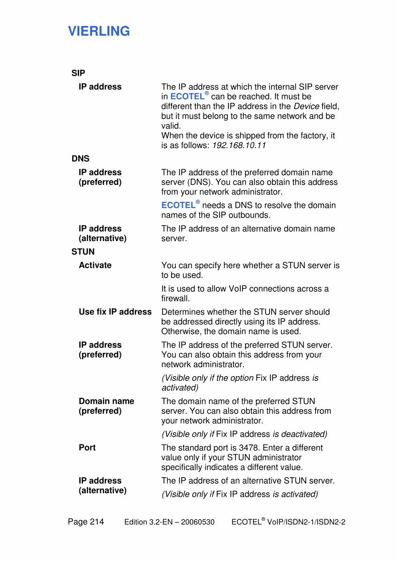
VIERLING
Page 214 Edition 3.2-EN – 20060530 ECOTEL® VoIP/ISDN2-1/ISDN2-2
SIP
IP address The IP address at which the internal SIP server in ECOTEL
® can be reached. It must be
different than the IP address in the Device field, but it must belong to the same network and be valid. When the device is shipped from the factory, it is as follows: 192.168.10.11
DNS
IP address (preferred)
The IP address of the preferred domain name server (DNS). You can also obtain this address from your network administrator.
ECOTEL® needs a DNS to resolve the domain
names of the SIP outbounds.
IP address (alternative)
The IP address of an alternative domain name server.
STUN
Activate You can specify here whether a STUN server is to be used.
It is used to allow VoIP connections across a firewall.
Use fix IP address Determines whether the STUN server should be addressed directly using its IP address. Otherwise, the domain name is used.
IP address (preferred)
The IP address of the preferred STUN server. You can also obtain this address from your network administrator.
(Visible only if the option Fix IP address is activated)
Domain name (preferred)
The domain name of the preferred STUN server. You can also obtain this address from your network administrator.
(Visible only if Fix IP address is deactivated)
Port The standard port is 3478. Enter a different value only if your STUN administrator specifically indicates a different value.
IP address (alternative)
The IP address of an alternative STUN server.
(Visible only if Fix IP address is activated)

VIERLING
ECOTEL® VoIP/ISDN2-1/ISDN2-2 Edition 3.2-EN – 20060530 Page 215
Domain name (alternative)
The domain name of an alternative STUN server.
(Visible only if Fix IP address is deactivated)
Port The standard port is 3478. Enter a different value only if your STUN administrator specifically indicates a different value.
Send NAT 'keep alive' every ... seconds
Determines the interval at which ECOTEL® logs
into the STUN server in order to maintain the STUN function even when there is no call.
VIERLING
Page 216 Edition 3.2-EN – 20060530 ECOTEL® VoIP/ISDN2-1/ISDN2-2
6.6.4 Basic Configuration: Device
Call: In the Basic Configuration main window, select the Device tree node.
The structure and function of this page corresponds to that of the page with the same name in the Gateway Configuration module (see there).
6.3.13 Gateway Configuration: Device
VIERLING
ECOTEL® VoIP/ISDN2-1/ISDN2-2 Edition 3.2-EN – 20060530 Page 217
6.7 Monitor module
Note: This module is not available with ECOTEL
®ISDN2-1.
The Monitor module is used to display the status of each channel of a gateway (ECOTEL
®). It is also possible to generate statistics,
e.g. about the utilization of individual channels or the complete gateway. The data are called up by the gateway at an adjustable time interval and displayed in the software interface.
Note: To allow access to the monitoring information on the computer, the Activate online monitoring box must be checked in the Gateway Configuration module under Maintenance.
When you exit the Monitor window, you will be automatically returned to Service Gear.
VIERLING
Page 218 Edition 3.2-EN – 20060530 ECOTEL® VoIP/ISDN2-1/ISDN2-2
6.7.1 Monitor: Main window
Call: From all modules via Tools > Start > Monitor.
The structure and functioning of the operating elements corre-sponds to the main window in the Routing Table module; see there.
The elements of the tree view and the corresponding detail win-dows which are described in the following sections are different.
VIERLING
ECOTEL® VoIP/ISDN2-1/ISDN2-2 Edition 3.2-EN – 20060530 Page 219
6.7.2 Monitor: Channels
Call: In the Monitor main window, mark the Channels tree node.
This displays all of the channels which are supported by the hardware along with their status.
Channel Name of the channel: G 1..n; I 1, I 2; V 0, V 1..n
(V 0: via internal SIP server; V 1, V 2, ...: via external SIP outbound 1, 2, ...)
Type Interface type: GSM, ISDN or VoIP
State Availability of the channel:
(Green icon) Channel is ready (or special case: roaming, low funds)
(Yellow icon) Channel has been deactivated; or, in case of a VoIP channel, the corresponding SIP outbound is not configured
(Blue icon) Channel is being prepared (wait for ready) (or more specific: searching, reboot)
(Red icon) Channel has encountered an error (or more specific error cause)
IMSI (Only with GSM channels:) IMSI of the GSM module
IMEI (Only with GSM channels:) IMEI of the GSM module
VIERLING
Page 220 Edition 3.2-EN – 20060530 ECOTEL® VoIP/ISDN2-1/ISDN2-2
6.7.3 Monitor: Statistics
Call: In the Monitor main window, mark the Statistics tree node.
Statistical data are displayed about the calls that were made.
The data are from the file ECOTEL.mon on the device. These data are retained even when the firmware is updated.
Channel Name of the channel: G 1..n; I 1, I 2; V 0, V 1..n
(V 0: via internal SIP server; V 1, V 2, ...: via external SIP outbound 1, 2, ...)
Incoming Number of incoming calls (in the direction of ECOTEL
®)
Outgoing Number of outgoing calls (routed along by ECOTEL
®)
Connections Number of calls for which a connection to the B subscriber was made
APartner disc. Number of calls which were disconnected by the A subscriber before the call could go through
BPartner busy Number of calls for which the B subscriber was busy
Local busy Number of calls for which the outgoing port of ECOTEL
® or the network between ECOTEL
®
and the B subscriber was blocked
ASR 1 (Average Seizure Ratio 1): Percentage of calls for which a connection was made, including calls disconnected by the A subscriber; = (Outgoing – local busy) / Outgoing * 100
ASR 2 (Average Seizure Ratio 2): Percentage of calls for which a connection was made, without the calls disconnected by the A subscriber; = (Outgoing – local busy – APartner disc.) / Outgoing * 100
VIERLING
ECOTEL® VoIP/ISDN2-1/ISDN2-2 Edition 3.2-EN – 20060530 Page 221
Avg duration [s] Average connection duration (in seconds); = Duration / Connections
Duration [s] Total duration of all calls with a completed connection (in seconds)
Clear Statistics Deletes all of the existing statistical data
VIERLING
Page 222 Edition 3.2-EN – 20060530 ECOTEL® VoIP/ISDN2-1/ISDN2-2
6.7.4 Monitor: Connections
Call: In the Monitor main window, mark the Connections tree node.
This page displays online all of the connections which are passing via ECOTEL
®.
Note: To allow access to the monitoring information on the computer, the Activate Online Monitoring box must be checked in the Gateway Configuration module under Maintenance.
Terminated connections remain in the list (indicated using a red font) until the set time duration has elapsed or the window is closed.
Port In Input channel on ECOTEL®
Calling Party Number of the calling party
Port Out Output channel on ECOTEL®
Called Party Number of the called party
Status Status of the connection. Possible values:
Setup Connection being established
Alert B subscriber being alerted
Connect Connected
Release Connection terminated
Call Duration [s] Connection length (in seconds)
Display options
Remove released connections after
Terminated connections are deleted from the list after the set time duration (in seconds).
VIERLING
ECOTEL® VoIP/ISDN2-1/ISDN2-2 Edition 3.2-EN – 20060530 Page 223
6.7.5 Monitor: SIM Statistics
Call: In the Monitor main window, mark the SIM Statistics tree node.
Here, you will see information on using the individual SIM cards.
Module
GSM1 (2, ...) This line shows the SIM cards that belong to GSM module 1 (or 2, ...).
Time
Limit Maximum permissible call duration for the relevant SIM card (can be set in the SIM Management module under GSM 1 (2, ...))
Charged The call duration charged by the provider. The entire interval is counted for charge intervals that are begun.
Used The actual call duration without taking into account the charge intervals
Location A (B, ...) Card position (slot) on the SIM cardholder
Total This column shows the totals for Limit, Charged, Used for all of the SIM cards in a GSM module.
Reset SIM counters of
Resets the Charged and Used values to zero. The Limit value is not modified.
You can use this function after exchanging SIM cards, for example (there is no automatic reset).
Module The reset applies to all of the SIM cards in a module. Select a module beforehand by clicking on the GSM 1 (2, ...) button.
Single card The reset applies to only a single SIM card. Select a SIM card beforehand by clicking on one of the three number fields for the card.
All The reset applies to all of the SIM cards in ECOTEL
®.
VIERLING
Page 224 Edition 3.2-EN – 20060530 ECOTEL® VoIP/ISDN2-1/ISDN2-2
Display options
h:mm:ss m:ss s
Switches the time format (display in hours, minutes or seconds).
Show index Displays the absolute index for each SIM card. This number is used (instead of the module no. + location no.) to designate the card, e.g. in trace reports.
VIERLING
ECOTEL® VoIP/ISDN2-1/ISDN2-2 Edition 3.2-EN – 20060530 Page 225
6.8 SIM Management module
Note: This module is not available with ECOTEL
®ISDN2-1.
The SIM Management module has two functions: On the one hand, setup data (mobile radio numbers, etc.) for the SIM cards are managed here. On the other hand, you can control the switching here, i.e. automatic switching between SIM cards.
Assigning SIM cards to GSM channels
Each GSM module in your ECOTEL® corresponds to a GSM
channel which can be used to make calls. You can assign multiple SIM cards to each GSM channel (2, 4 or 8 SIM cards depending on the type of SIM cardholder you are using).
Each SIM card has a fixed assignment to a GSM channel, i.e. the card can be used only for this one channel.
On the SIM cardholder, the slots for the individual cards are labeled as 1A, 1B, ... 2A, 2B, ... They are related as follows:
GSM channel 1 Cardholder in SIM slot 1 Cards 1A, 1B, ...
GSM channel 2 Cardholder in SIM slot 1 Cards 2A, 2B, ...
GSM channel 3 Cardholder in SIM slot 1 Cards 3A, 3B, ...
GSM channel 4 Cardholder in SIM slot 1 Cards 4A, 4B, ...
GSM channel 5 Cardholder in SIM slot 2 Cards 1A, 1B, ...
GSM channel 6 Cardholder in SIM slot 2 Cards 2A, 2B, ...
GSM channel 7 Cardholder in SIM slot 2 Cards 3A, 3B, ...
GSM channel 8 Cardholder in SIM slot 2 Cards 4A, 4B, ...
When it is clear which GSM channel we mean, we sometimes use card A, B, ... for short.

VIERLING
Page 226 Edition 3.2-EN – 20060530 ECOTEL® VoIP/ISDN2-1/ISDN2-2
Groups of SIM cards
The SIM cards belonging to a GSM channel can be divided into groups. Switching always occurs within a group. You can specify when each group is valid.
This makes it possible, for example, to use cards for provider X at certain times and cards for provider Y the rest of the time in order to take advantage of the best rates.
For each GSM channel, up to 10 groups can be used. The settings are made in windows SIM Group 1 to SIM Group 10 underneath the appropriate tree node GSM 1 (2, 3, ...).
6.8.4 SIM Management: GSM 1..n: SIM Group 1..10
For each GSM channel, at least one group with associated SIM cards must exist in order to allow outgoing calls via this channel. A SIM card must be associated with at least one group in order to be used.
When the device is shipped from the factory, (only) the SIM card in slot 1A is assigned to SIM Group 1 and this group is activated for the entire time. All calls take place via this single SIM card.
You can also assign a card to multiple groups. ECOTEL® inter-
prets this as follows: If an outgoing call is to be set up via a GSM channel, ECOTEL
® checks the associated groups in order starting
with group 1. If a group is found which is currently valid and con-tains at least one usable card, its settings are used and the following groups are ignored. If ECOTEL
® does not find a usable
group (time condition not fulfilled anywhere, cards expired, etc.), the call is not made.
Warning: Make sure that your group settings are compatible with the entries in the routing table!
For example, if the routing table stipulates that a call is to be routed via GSM port x but no SIM card group is currently valid for GSM x at this time, the call will not be made. The same thing will happen if SIM cards are enabled via the group but the routing table does not allow the call.

VIERLING
ECOTEL® VoIP/ISDN2-1/ISDN2-2 Edition 3.2-EN – 20060530 Page 227
6.8.1 SIM Management: Main window
Note: The main window is labeled ECOTEL Configuration Software in the title bar. It is distinguished from the main window of the Gateway Configuration module by a different tree view.
Call: From any of the modules, using Tools > Start > SIM Management.
Operating elements
The operating elements are the same as the ones used in the Gateway Configuration main window (see there).
The main difference is that here in Basic Configuration, configu-ration files of type *.SMC are processed which contain settings for the administration of SIM cards.
The information under Gateway Configuration about the peculi-arities of the file name ECOTEL.UPB also apply to the file name ECOTEL.SMC.
6.3.1 Gateway Configuration: Main window
VIERLING
Page 228 Edition 3.2-EN – 20060530 ECOTEL® VoIP/ISDN2-1/ISDN2-2
6.8.2 SIM Management: SIM Cardholder
Call: In the SIM Management main window, mark the SIM Cardholder tree node.
SIM management center
External (connected via IP)
Management of the SIM cards via an external SIM management center
IP address IP address of the external SIM management center
If the SIM emulation board is selected under SIM slot 1 or 2, enter the IP address of the SIM server on which the cards are located.
Local SIM configuration
Management of the SIM cards locally in ECOTEL
®; settings are made in the SIM
Management module
SIM slot 2 Indicate here the type of SIM cardholder in slot 2 (for GSM modules 5-8)
SIM slot 1 Indicate here the type of SIM cardholder in slot 1 (for GSM modules 1-4)
VIERLING
ECOTEL® VoIP/ISDN2-1/ISDN2-2 Edition 3.2-EN – 20060530 Page 229
6.8.3 SIM Management: GSM 1..n
Call: In the SIM Management main window, mark the GSM 1 (2, 3, ...) tree node.
GSM module n - available SIM cards
Lists the available SIM cards for this GSM module. How many depends on the setting under SIM cardholder.
Inserted at Select here the SIM card you wish to edit. The data for the relevant card are displayed in the Properties field.
Use data of first card at all cards of this module
You may use the buttons of this group for easier editing if SIM properties are the same for all SIM cards belonging to this module.
Warning: By using the copying functions, all previous data will be overwritten without warning!
Copy PIN Copies the PIN of SIM card A to SIM cards B, C, etc.
Copy clock model
Copies the properties under Clock model in seconds of SIM card A to SIM cards B, C, etc.
Copy LAIN condition
Copies the properties under Lock to preferred LAIN of SIM card A to SIM cards B, C, etc.
Copy calltime limit
Copies the properties under Calltime limit for each SIM card of SIM card A to SIM cards B, C, etc.
Copy service center number
Copies the Service center number of SIM card A to SIM cards B, C, etc.
Copy all Copies all of the above properties of SIM card A to SIM cards B, C, etc. The Mobile number is not copied.
Properties
PIN Enter the PIN for the SIM card here. The PIN is used by ECOTEL
® for authentication with
respect to the SIM card.
The PIN is transmitted to ECOTEL®.when the
configuration file is downloaded.
VIERLING
Page 230 Edition 3.2-EN – 20060530 ECOTEL® VoIP/ISDN2-1/ISDN2-2
Warning: Do not insert SIM cards into the device before configuring the correct PINs and only modify a PIN when the SIM card is removed since otherwise access problems and blockage of the card can possibly result.
The sequence is as follows: – Remove the old SIM card(s) (if necessary) – Enter the new PIN(s) – Transmit the configuration to ECOTEL
®
– Insert the new SIM card(s)
Note: To change the PIN on the actual card, insert it into a mobile phone and perform the procedure required there. You cannot make such a change using ECOTEL
®.
Clock model in seconds
Here, you should enter the charge timing for the rate model for the installed SIM card. This value is used to compute when the call time limit is reached (see below). The first entry indicates the duration of the first charge pulse in seconds and the second entry indicates the spacing between all subsequent pulses.
Example: 60 / 1 means that for the first pulse, the charges are computed for 60 seconds, while for each further pulse the charges are computed for one second.
Lock to preferred LAIN
LAIN Here, you should enter the LAIN (Location Area Identification Number) of the GSM network in which the installed SIM card should register.
If no LAIN is entered, the SIM card will register in the network with the best reception.
You can get more details about the network operators which are available locally in the Firmware Tools module on the GSM parameters page.
VIERLING
ECOTEL® VoIP/ISDN2-1/ISDN2-2 Edition 3.2-EN – 20060530 Page 231
Roaming allowed
If roaming is allowed, a SIM card can also register in an outside GSM network if registration fails under the specified LAIN.
If roaming is not allowed, the SIM card may only register under the specified LAIN.
Overall calltime limit
You can set a maximum for the total duration of all calls via this SIM card. If this limit is reached, ECOTEL
® will not use this SIM card any longer.
This allotment is applicable to a certain time period, e.g. per month. After this, the counter is reset and the allotment is available again.
Use limit of ... minutes
Call time permitted per interval
per ... Length of the standard interval
starting (dd.mm.yyyy) ...
Start of the first interval (at 00:00 on the specified day)
Mobile number Telephone number of the SIM card which is installed in the GSM module.
Service center number
Number of the SMS service center for the SIM card which is installed. This number is needed so that ECOTEL
® can send SMS messages.
Info Enter your notes here (deactivated in the present version)
VIERLING
Page 232 Edition 3.2-EN – 20060530 ECOTEL® VoIP/ISDN2-1/ISDN2-2
6.8.4 SIM Management: GSM 1..n: SIM Group 1..10
Call: In the SIM Management main window under the GSM 1 (2, 3, ...) node, mark the tree node SIM Group 1 (2, 3, ...).
For more details about using the groups, see:
6.8 SIM Management module
Usage
On ... Days of the week on which the group is to be used
from ... to ... Start and end of the time of day interval during which the group is to be used (hours : minutes)
use SIM card(s) ... SIM cards (for the selected GSM channel) which should belong to the group
Switch card: Determines when to switch to another SIM card:
Never Never; always use card A
When 'time registered' exceeds ...
When the total time during which the card was registered exceeds the limit
When 'active call time' exceeds ...
When the total duration of calls made exceeds the limit
When 'outgoing calls' exceed ...
When the number of outgoing calls exceeds the limit
(limit) Entry field for the limit
Execute switching: Determines how to handle calls which are underway at the switching time:
Immediately Switch immediately and interrupt call
When active call has been released
Switch after call is complete
... but at least after ... seconds
ECOTEL® first waits for the "natural" end of the
call, but after the set time interval it interrupts the call and makes the switch.
VIERLING
ECOTEL® VoIP/ISDN2-1/ISDN2-2 Edition 3.2-EN – 20060530 Page 233
Switch algorithm Determines which card is next in line
'Round Robin' (use next card)
The cards are used in order and the last card is followed by the first card
Take 'least used' card
The least used card, i.e. the one with the least active call time, is used next
Take 'least used' card, but different from last
As before, but the last card used is excluded
Charging information
This determines for incoming calls from the GSM side what charging information should be made available to the ISDN side. Possible values: Generate none, or Generate in ECOTEL.
Forwarding of charging information from the GSM network is not possible currently since GSM networks do not send this information.
The following parameters control the generation of charge units by ECOTEL
®:
t1 Duration of the first charging interval
x1 Transferred units for the first charging interval
t2 Duration of each additional charging interval
x2 Transmitted units for each additional charging interval
Note: The extent to which this information on the ISDN side is forwarded to the called subscriber depends on the settings for the ISDN interface!
6.3.3 Gateway Configuration: ISDN Interface 1/2

VIERLING
Page 234 Edition 3.2-EN – 20060530 ECOTEL® VoIP/ISDN2-1/ISDN2-2
6.8.5 SIM Management: Device
Call: In the SIM Management main window, select the Device tree node.
The structure and function of this page corresponds to that of the page with the same name in the Gateway Configuration module (see there).
6.3.13 Gateway Configuration: Device
VIERLING
ECOTEL® VoIP/ISDN2-1/ISDN2-2 Edition 3.2-EN – 20060530 Page 235
6.9 User Registration module
The User Registration module is used to manage VoIP users of ECOTEL
®. On the one hand, you can determine the parties that
ECOTEL® will accept incoming calls from via the VoIP interface.
On the other hand, you can list the users that can be reached via ECOTEL
®’s internal SIP server as VoIP call destinations.
Note: This module is only available with ECOTEL
®VoIP.
When you exit the User Registration window, you will be automatically returned to Service Gear.
VIERLING
Page 236 Edition 3.2-EN – 20060530 ECOTEL® VoIP/ISDN2-1/ISDN2-2
6.9.1 User Registration: Main window
Call: From all modules via Tools > Start > User Registration.
The structure and functioning of the operating elements corre-sponds to the main window in the Routing Table module; see there.
The elements of the tree view and the corresponding detail win-dows which are described in the following sections are different.
VIERLING
ECOTEL® VoIP/ISDN2-1/ISDN2-2 Edition 3.2-EN – 20060530 Page 237
6.9.2 User Registration: Allowed Users
Call: In the User Registration main window, mark the Allowed Users tree node.
(User table) Shows all authorized users of ECOTEL®, i.e.
the users that may register with the device. This includes users that can be reached as a call destination via ECOTEL
®’s internal SIP server
as well as callers (including SIP outbounds) on the VoIP interface from whom calls are to be accepted.
Domain The domain name of the user.
If "*" is entered, ECOTEL® will accept any user.
This is valid only if "*" is also entered as a user.
User The user name.
If "*" is entered, ECOTEL® will accept any user
from the domain. In this case, the password is ignored.
Password The related password.
It can be "*" if the user is also "*". Otherwise, a password must be entered.
Authentication Id Separate user identifier for authentication, if required
Comment Enter any comment about the user table.
Entry
Note: The functions New, Edit and Delete are also accessible via context menu (right mouse-click).
Double-click on an empty table row has the same effect as New.
Double-click on the desired table row has the same effect as Edit.
New... Opens the User Registration edit dialog to add a new table entry.
VIERLING
Page 238 Edition 3.2-EN – 20060530 ECOTEL® VoIP/ISDN2-1/ISDN2-2
Edit... Opens the User Registration edit dialog to edit the selected table entry.
Delete Deletes the marked table entries.
Moves the marked table entry up or down within the list.
File
Upload from Ecotel
Reads the current user table from ECOTEL®
and displays it the left half of the window.
Note: The file which is read out always has the name USER.TXT. The read operation from ECOTEL
® causes the user table which was
previously open to be discarded and the existing file USER.TXT is overwritten on the configuration computer (after asking for confirmation).
Download to Ecotel
Transmits the displayed user table to ECOTEL®
where it immediately goes into effect after transmission.
Note: No check is made to see whether the entries in the user table have logical values (similar to the routing table). Please be sure to follow the instructions given above!
Note: The transmitted file is always saved on ECOTEL
® under the name USER.TXT.
New Discards the previously opened user table and creates a new one.
Open… Displays an Open File dialog which can be used to select a user table saved on the computer.
Save As… Displays a Save File dialog which can be used to save the displayed user table on the configuration computer.
VIERLING
ECOTEL® VoIP/ISDN2-1/ISDN2-2 Edition 3.2-EN – 20060530 Page 239
7 Making calls via ECOTEL
VIERLING
Page 240 Edition 3.2-EN – 20060530 ECOTEL® VoIP/ISDN2-1/ISDN2-2
7.1 Overview: What ECOTEL users must know
During call setup with ECOTEL®, users should be aware of two
peculiarities compared to the usual call procedure:
With some connection types (but not in LCR mode, for example), the user must dial ECOTEL
® first, i.e. the number of one of the
interfaces via which ECOTEL® can be reached (e.g. its extension
number or mobile radio number). Of course, the user will ideally choose the number which can be accessed the easiest or the most cost-effectively from his own telephone. ECOTEL
® will
respond with a voice announcement. Now, the user can dial the actual telephone number (no need to wait for the end of the voice announcement) and is then connected by ECOTEL
® to that
number.
The second peculiarity concerns the end of dialing: With the destination phone number, ECOTEL
® must recognize whether it is
already complete or whether there are further digits to follow. For this purpose, it is possible to define fixed phone number lengths in the routing table for specific destinations (e.g. this would make sense for mobile radio or extension numbers). In the remaining cases, the sequence of digits must be terminated with the number sign #. ECOTEL
® interprets a pause greater than 10 seconds as
the end of dialing.
Calls are routed by ECOTEL® depending upon the destination
number, the originating number or the redirecting number using defined ports (I11, I12, I21, I22, G1, G2, V, V1, V2), port groups (I, G, I1, I2) or port lists.
The routing is stored in the RTBL.TXT file. You can edit this routing table in the Routing Table module. See the separate section for information about the routing options along with some sample settings.
5 Introduction to the routing table
The examples given in the following sections relate to connections between the ISDN fixed network and the mobile radio network. However, they can also the applied to connections between the VoIP network and the mobile radio network.
VIERLING
ECOTEL® VoIP/ISDN2-1/ISDN2-2 Edition 3.2-EN – 20060530 Page 241
7.2 Outgoing calls
7.2.1 Calls to an arbitrary mobile network subscriber
Operational sequences are different depending upon the type of connection that has been selected for ECOTEL
®. The caller will
be supported with appropriate voice messages and/or tone signals in each instance.
When ECOTEL® is used as a terminal device on an internal
extension (in a multi-device configuration), the following procedure applies:
» Select the ECOTEL®
extension.
» ECOTEL® should respond with the following
announcement: "Mobile phone connection here."
» Dial the phone number of the desired mobile phone
subscriber. It is not necessary to wait until the voice announcement is completed.
Note: ECOTEL®
's factory default setting is set for a dialing length of 11 digits for national traffic and 14 digits for special services. Exceptions to the pre-defined lengths of phone numbers must be entered in the routing table. Dialing should be completed by inputting a # (number sign) for telephone numbers with less digits.
» ECOTEL® confirms reception of the number to be dialed
with the voice announcement: "The call is being set up. Please wait."
» Wait until the connection has been established and then
complete the call.
VIERLING
Page 242 Edition 3.2-EN – 20060530 ECOTEL® VoIP/ISDN2-1/ISDN2-2
For all other applications, these steps are not required. Instead, the following numbers should be dialed directly:
Connection as a terminal device with point-to-point connection (Terminal Equipment = TE, point-to-point connection):
» Only the number of the mobile network subscriber should
be dialed.
(It is assumed that the PBX routes all calls made to destinations in the mobile network to ECOTEL
®’s
extension.)
Connection on the exchange side to a PBX (Network Termination = NT, point-to-point connection):
» The sequence should be dialed consisting of ECOTEL®’s
exchange code + telephone number of the desired mobile phone connection.
Direct S0 bus connection (Network Termination = NT, point-to-multipoint connection, power supply unit may be necessary):
» Only the telephone number of the desired mobile network
connection should be dialed.
Warning: A dialing pause of 10 seconds between digits is interpreted as the end of a telephone number. If the # (number) key is pressed after the last digit, dialing is immediately executed (applies only to DTMF dialing in the voice channel). The timeout can be reduced in the configuration.
VIERLING
ECOTEL® VoIP/ISDN2-1/ISDN2-2 Edition 3.2-EN – 20060530 Page 243
7.2.2 Calls using speed dialing
ECOTEL® is capable of completing telephone numbers with the
routing table. This function can be used to define speed-dialing numbers.
Example:
By dialing 123, the telephone number 01701234567 is dialed, and by dialing 56, the telephone number 01701111111 is dialed:
Entry in the routing table:
#Speed-dial list (d123) n G:01701234567 (d56) n G:01701111111
VIERLING
Page 244 Edition 3.2-EN – 20060530 ECOTEL® VoIP/ISDN2-1/ISDN2-2
7.2.3 Setting up fixed connections
(Call forwarding to a mobile phone)
When required instead of manual destination dialing, ECOTEL®
can be set so that a call will be made to a pre-determined telephone number in the mobile network.
This function is controlled using entries in the routing table.
Example:
Extension 123 should always be connected to the telephone number 01701234567.
Entry in the routing table:
#Fixed connection (o123) n G:01701234567
VIERLING
ECOTEL® VoIP/ISDN2-1/ISDN2-2 Edition 3.2-EN – 20060530 Page 245
7.3 Incoming calls
7.3.1 Dialing an extension by the caller
(if your terminal device supports DTMF)
First, the caller dials ECOTEL®
’s mobile network number. After the call has been successfully set up, ECOTEL
® makes the voice
announcement: “Mobile radio connection here. Please input the extension number."
The caller inputs the extension number and completes the sequence with # (number sign). It is not necessary to wait until the voice announcement is completed:
0 1 7 1 x x x x x x x x x x # Radio network number Extension number
Note: If you have defined the number of digits for the local extension in the routing table, it is not necessary to input the # in order to mark the end of the extension telephone number.
5.4.4 Calls to an arbitrary extension (Example 2)
VIERLING
Page 246 Edition 3.2-EN – 20060530 ECOTEL® VoIP/ISDN2-1/ISDN2-2
7.3.2 Routing calls to a fixed extension
An option is available to route all calls to a predetermined extension of your PBX. All necessary information must be entered into the routing table.
The caller only has to dial the ECOTEL®
’s mobile network number. The caller incurs costs only when the fixed extension responds.
ECOTEL® also offers the option of reaching several extensions
that have been predetermined. This is dependent upon the caller's telephone number.
Example:
All incoming calls from the mobile network (starting with 01) are to be routed to extension 100 (the telephone exchange).
Entry in the routing table:
#Incoming calls to extension 100 (o01) n I1:100

VIERLING
ECOTEL® VoIP/ISDN2-1/ISDN2-2 Edition 3.2-EN – 20060530 Page 247
7.3.3 Redialing or new dialing
If the desired subscriber number is occupied, if no one picks up or if several calls are to be made, then new dialing can be performed within a PBX. This eliminates the need to make a new call each time over the mobile network.
If an extension is erroneously dialed, then new dialing allows a correction. If required, new dialing can be used repeatedly during a call.
If the subscriber is busy, the caller hears either a busy signal or a voice announcement. If the number is busy, 10 seconds are available in which to begin dialing a new number.
Note: To be able to use new dialing, the options Release on completed or Release on busy (Gateway Configuration module > GSM Interface 1..n) must be deactivated so that ECOTEL
® does not interrupt the connection to the calling
party.
New dialing within a PBX
» Without hanging-up, dial:
* x x x #
After entering "#" at the end of the procedure, entering the extension number is regarded as complete, and the connection will be set up. See also the following section:
7.3.1 Dialing an extension by the caller
VIERLING
Page 248 Edition 3.2-EN – 20060530 ECOTEL® VoIP/ISDN2-1/ISDN2-2
7.3.4 Call forwarding
During a call, the called subscriber B can connect the calling subscriber A to a third subscriber C.
» Dial without first hanging up:
* 2 # <Telephone number for C> #
Since subscriber A is still the calling party, the forwarding must be permissible in compliance with the routing table.
VIERLING
ECOTEL® VoIP/ISDN2-1/ISDN2-2 Edition 3.2-EN – 20060530 Page 249
7.4 Call hold switching between subscribers
Note: This feature is currently available only with ECOTEL®ISDN2-1.
Initiating call hold
If there is already a connection between a calling subscriber A and a called subscriber B, either of these two parties can initiate call hold, i.e. make an additional call to subscriber C.
» Without hanging up beforehand, dial:
* 3 # <Telephone number for C> #
Note: A separate GSM channel (i.e. a separate SIM card) must be available for each GSM subscriber.
If the additional called subscriber C does not answer, the subscriber who initiated the procedure can restore the old connection as follows:
» Dial the key combination * 3 #
If the called subscriber C is busy or there is not a free GSM or ISDN channel in ECOTEL®, then the old connection will be automatically restored.
If the new call is successful, the existing called party of the subscriber who is carrying out this procedure will be put on hold, i.e. the party will hear a hold announcement or music until the other party switches back.
VIERLING
Page 250 Edition 3.2-EN – 20060530 ECOTEL® VoIP/ISDN2-1/ISDN2-2
Switching between the different calls
Once the call is connected to C, the subscriber who initiated the call hold procedure can switch between the two calls:
» Dial the key combination * 3 #
Forwarding a call
The subscriber who initiated the call hold procedure can connect the other two parties. He or she will be disconnected:
» Dial the key combination * 4 #
Ending call hold
Call hold ends when one of the parties hangs up. The subsequent connection status depends on which party hung up:
– If the original calling subscriber A initiated the call hold
procedure and hangs up, all of the connections will end.
– If the original called subscriber B initiated the call hold
procedure and hangs up, A and C will be connected. (B can achieve the same effect by forwarding the call with * 4 #.)
– If the currently held subscriber hangs up, the remaining
active connection will be maintained. If the subscriber who initiated the call hold procedure later attempts to switch back to the subscriber who was on hold, he or she will hear an announcement that this party is no longer available.
– If the currently active subscriber (who did not initiate call
hold) hangs up, the connection will be reconnected between the party who initiated call hold and the party on hold.
Once one party to a call initiates a call hold procedure, the other two parties cannot initiate a call hold procedure themselves.
If the call hold procedure is terminated by one of the subscribers hanging up and the connection remains between the other two
VIERLING
ECOTEL® VoIP/ISDN2-1/ISDN2-2 Edition 3.2-EN – 20060530 Page 251
subscribers, at this point either of these two subscribers can initiate a call hold procedure if desired.
VIERLING
Page 252 Edition 3.2-EN – 20060530 ECOTEL® VoIP/ISDN2-1/ISDN2-2
8 Additional topics and background information

VIERLING
ECOTEL® VoIP/ISDN2-1/ISDN2-2 Edition 3.2-EN – 20060530 Page 253
8.1 Overview: Gaining a better understanding of ECOTEL
This section includes some additional background information. You can refer to this section when you want to get a better grasp of the basic concepts behind ECOTEL
®.
VIERLING
Page 254 Edition 3.2-EN – 20060530 ECOTEL® VoIP/ISDN2-1/ISDN2-2
8.2 Interpretation of the interface version
The following modules in Service Gear are used to process configuration files for ECOTEL
®: Gateway Configuration, Basic
Configuration and SIM Management.
If new features are added to ECOTEL® as part of the product
development process, it is possible that parameters will be added to the configuration files or modified. However, it should still be possible to manage devices with older software versions using Service Gear.
Accordingly, these modules use what is known as interface versions. This means that the user interface of the module is available in different versions. The versions differ in terms of the parameters that can be viewed by the user and the parameters that are contained in the configuration files that are generated.
You can specify the interface version by accessing the menu item File > New... and selecting a version in the dialog that follows. The version must agree with the firmware version used in ECOTEL
®.
This is selected separately in each of the modules listed above.
You can view the selected interface version later at any time on the page Device in the relevant module.
Please be aware that this manual always describes the latest interface version for these modules. Older interface versions can differ from what is described here.
The interface version is not relevant in the other modules.
VIERLING
ECOTEL® VoIP/ISDN2-1/ISDN2-2 Edition 3.2-EN – 20060530 Page 255
8.3 ECOTEL Glossary
This section explains some of the terms which in some cases have a specific meaning in relation to ECOTEL
® when compared
to everyday usage.
Access code
This is used during –›Remote access by the –›Modem in order to authenticate itself to ECOTEL
®. This also allows ECOTEL
® to
recognize the remote access procedure (as opposed to a normal call).
Do not confuse the –›Access code with the –›Security code.
Configuration computer
The computer (PC, laptop) which is used to configure ECOTEL®.
Direct access
See –›Remote access
Download
In ECOTEL®: Data transmission from the configuration computer
to ECOTEL®.
ECOTEL code
An older term for –›PUK
Incoming (arriving) call
See –›Outgoing call
VIERLING
Page 256 Edition 3.2-EN – 20060530 ECOTEL® VoIP/ISDN2-1/ISDN2-2
Modem
In everyday terms, this is a device which is used in data trans-mission to convert data between different interface types, e.g. from a serial computer interface to an analog telephone line.
In ECOTEL®: A device which enables access by the configuration
computer to an ECOTEL® via its GSM interface. Here, an
ECOTEL® is also used typically. For more information, see the
following section:
4.3.2 Connecting via modem
Outgoing call
In ECOTEL®: A call in which an extension of the PBX calls via
ECOTEL® an “external” destination in the fixed network, GSM
network or VoIP network.
An incoming (arriving) call takes place in the opposite direction.
Together, ECOTEL® and the PBX with its extensions are
considered as "here".
(If we consider ECOTEL® alone, all calls are "transient", meaning
they arrive via some interface and leave via some other interface.)
PUK
In general terms: Personal unblocking key (a code which is entered to unblock a device).
In ECOTEL®: An additional security code (also known as –›Secu-
rity code 2).
If the normal –›Security code is incorrectly entered multiple times, it is automatically blocked. To unblock it, it is necessary to use the PUK instead of the normal security code.
6.5.3 Firmware Tools: Security Code
Remote access, remote connection
A technique which the –›Configuration computer uses to access a remote ECOTEL
®.
VIERLING
ECOTEL® VoIP/ISDN2-1/ISDN2-2 Edition 3.2-EN – 20060530 Page 257
Using a –›Modem, a connection is established to ECOTEL® via
GSM. The transmission path from the computer via the modem to ECOTEL
® is referred to as the Remote access or Remote
connection. For more information, see the following section:
4.3.2 Connecting via modem
The other possibility is Direct access by the computer to ECOTEL
® via IP, USB or serial cable.
Security code
The code which the –›Configuration computer uses to identify itself to ECOTEL
® (authentification).
During –›Remote access, besides the security code for the ECOTEL
® to be configured, the security code for the –›Modem is
also important since the configuration computer must also authenticate itself to the modem.
See also the –›Access code.
Security code 2
Same as –›PUK.
SIM PIN
The personal identification number (PIN) which is needed to log into a mobile radio network with a SIM card.
With a mobile phone, the user types in the PIN. With ECOTEL®,
the SIM PINs for all of the SIM cards are saved in the device and are passed to the relevant GSM module when needed.
SMC
Abbreviation for SIM Management Center.
Upload
In ECOTEL®: Data transmission from ECOTEL
® to the configu-
ration computer.
VIERLING
Page 258 Edition 3.2-EN – 20060530 ECOTEL® VoIP/ISDN2-1/ISDN2-2
8.4 General information about VoIP
Note: This section is relevant only for ECOTEL
®VoIP.
With voice over IP (VoIP), speech data do not travel over a tele-phone line. Instead, they are transmitted in packets, i.e. no line is connected from the caller to the called party. Speech information is transmitted in packets via the Internet to the destination address. The individual speech packets can follow different paths through the Internet and sometimes overlap one another. This means that packets which were sent later can arrive at the destination earlier than others. At the destination, it is necessary to put these speech packets back in the proper sequence and convert them into an analog speech signal.
Similar to ISDN, Internet telephony has a signaling channel for controlling the connection and a data channel for the speech information. ECOTEL
® uses SIP (session initiation protocol) for
controlling the connection. For use in transporting speech data, RTP (real-time transport protocol) is used.
VIERLING
ECOTEL® VoIP/ISDN2-1/ISDN2-2 Edition 3.2-EN – 20060530 Page 259
8.4.1 Explanation of VoIP terms
IP address
An IP address consists of four numbers from 0 to 255 which are separated from one another by periods. Such an address identifies a computer in the Internet.
Subnet mask
Along with the IP address, this number indicates the network to which your computer belongs.
A subnet mask has the same format as an IP address. It is conventional to only use 0 or 255 as values (e.g. 255.255.255.0). owever, other values can also occur. They indicate that subnetworks are used in a particular TCP/IP network.
Standard gateway
This is used to supplement the IP address of a computer. It is the address of a local IP router which is located in the same network as the relevant computer (here: ECOTEL
®) and which is used to
forward data traffic to destinations outside of the local area network. The value in this field must be in the range from 0 to 255.
A gateway is the connection or exchange via which IP networks are interconnected. For example, local area networks (LANs) often need a gateway in order to connect to a wide area network (WAN) or to the Internet.
User agent (UA)
In the context of VoIP, a user agent is a piece of hardware or software for SIP-based communication which offers the functions normally provided by conventional telephones (dialing, ringing, microphone, loudspeaker, etc.). A UA can act as a user agent client (UAC) or as a user agent server (UAS). A UAC is the initiator of a SIP communication (calling party, A subscriber). The UAS (called party, B subscriber) responds to the request of the
VIERLING
Page 260 Edition 3.2-EN – 20060530 ECOTEL® VoIP/ISDN2-1/ISDN2-2
UAC. As a general rule, in a VoIP telephone (hardware or software) both a UAC and a UAS are implemented. Depending on its role, a VoIP telephone can alternate between serving as a UAC and a UAS in the communication process.
Proxy server
A proxy server acts as a way station on the path from the calling UAC to the called UAS. In this configuration, the UAC does not send its messages (e.g. INVITE) directly to the UAS. Instead, it uses a proxy server. The proxy server forwards the message (e.g. INVITE) to the UAS and sends its response (e.g. 100-Trying or 180-Ringing) back to the UAC. In many cases, the proxy server is combined with a registrar.
Registrar
Any UA can register with the registrar server using the REGISTER message. The registrar then saves the current IP address and SIP address (SIP-URI) of the user. If necessary, other SIP elements, e.g., a proxy server, can access this information.
Redirector
A redirector (redirect server) saves information about the possible location of a user. Upon request, it passes this information back to the querying UA. However, the redirector does not actively attempt to find the user (unlike a proxy server). Instead, the querying UA must send a new request to the address(es) obtained from the redirector.
SIP server
A SIP server generally combines the proxy server, registrar and redirector components. Common synonyms for SIP server are soft PBX or IP PBX.
NAT
In computer networks, network address translation (NAT) is a technique for replacing an IP address in a data packet with a
VIERLING
ECOTEL® VoIP/ISDN2-1/ISDN2-2 Edition 3.2-EN – 20060530 Page 261
different IP. This is commonly used to map private IP addresses on public IP addresses.
NAT is required mainly because public IP addresses are becoming scarcer and private IP addresses can be used as needed in an internal (private) network. To allow communication over the Internet, the internal private addresses must be translated into public addresses at the gateway to the Internet (or to another public network).
Normally, NAT is performed at the interconnection between two networks. An NAT device can be a router or a firewall, for example.
STUN
STUN (Simple Traversal of UDP Over NATs) is a simple network protocol for detecting the presence and type of firewalls and NAT routers and for circumventing them. It is intended to enable straightforward usage of devices (e.g. SIP telephones) in home networks which wish to receive data from the Internet.
Using STUN, the current public IP address of the connection can also be determined. For example, this allows a SIP telephone behind a DSL router to determine its currently valid public IP address. The B subscriber is informed of this address and can now send response packets to this address.
VIERLING
Page 262 Edition 3.2-EN – 20060530 ECOTEL® VoIP/ISDN2-1/ISDN2-2
8.4.2 Codec
A codec (COmpressor/DECompressor) is a chip or algorithm which compresses data or speech and allows decompression of the same data or speech at the other of the connection. Various codecs have been standardized which compress speech data with different levels of quality loss in order to be able to transmit speech over channels with a narrower bandwidth or to transmit more channels over a fixed bandwidth. The following codecs are implemented in ECOTEL
®:
– G.711 PCM at 64 kbit/s
– G.726 and G.727 E-ADPCM at 16 to 40 kbit/s
– G.729/Annex A CS-ACELP at 8 kbit/s
– G.723.1 MP-MLQ/ACLEP at 6.3/5.3 kbit/s
Each codec can be activated or deactivated using the configuration software.
VIERLING
ECOTEL® VoIP/ISDN2-1/ISDN2-2 Edition 3.2-EN – 20060530 Page 263
8.4.3 VoIP and Security
By its very nature, telephony over the Internet requires transmission of signaling and speech data from a private IP network to the public IP network and vice versa. For technical reasons and also due to the security requirements of the private network, this has certain limitations.
Some important issues come up here in relation to the NAT problem (see above) and firewalls. This manual will not consider these problems in detail. We recommend that you study this issue in the context of VoIP.
VIERLING
Page 264 Edition 3.2-EN – 20060530 ECOTEL® VoIP/ISDN2-1/ISDN2-2
9 Special hardware-related issues
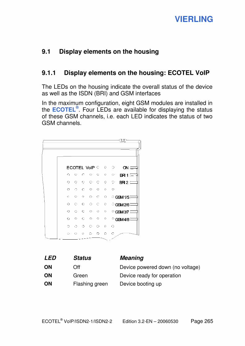
VIERLING
ECOTEL® VoIP/ISDN2-1/ISDN2-2 Edition 3.2-EN – 20060530 Page 265
9.1 Display elements on the housing
9.1.1 Display elements on the housing: ECOTEL VoIP
The LEDs on the housing indicate the overall status of the device as well as the ISDN (BRI) and GSM interfaces
In the maximum configuration, eight GSM modules are installed in the ECOTEL
®. Four LEDs are available for displaying the status
of these GSM channels, i.e. each LED indicates the status of two GSM channels.
LED Status Meaning
ON Off Device powered down (no voltage)
ON Green Device ready for operation
ON
Flashing green Device booting up
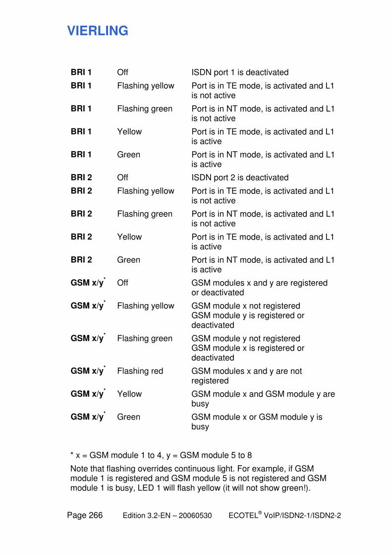
VIERLING
Page 266 Edition 3.2-EN – 20060530 ECOTEL® VoIP/ISDN2-1/ISDN2-2
BRI 1 Off ISDN port 1 is deactivated
BRI 1 Flashing yellow Port is in TE mode, is activated and L1 is not active
BRI 1 Flashing green Port is in NT mode, is activated and L1 is not active
BRI 1 Yellow Port is in TE mode, is activated and L1 is active
BRI 1 Green Port is in NT mode, is activated and L1 is active
BRI 2 Off ISDN port 2 is deactivated
BRI 2 Flashing yellow Port is in TE mode, is activated and L1 is not active
BRI 2 Flashing green Port is in NT mode, is activated and L1 is not active
BRI 2 Yellow Port is in TE mode, is activated and L1 is active
BRI 2 Green Port is in NT mode, is activated and L1 is active
GSM x/y* Off GSM modules x and y are registered
or deactivated
GSM x/y* Flashing yellow GSM module x not registered
GSM module y is registered or deactivated
GSM x/y* Flashing green GSM module y not registered
GSM module x is registered or deactivated
GSM x/y* Flashing red GSM modules x and y are not
registered
GSM x/y* Yellow GSM module x and GSM module y are
busy
GSM x/y* Green GSM module x or GSM module y is
busy
* x = GSM module 1 to 4, y = GSM module 5 to 8
Note that flashing overrides continuous light. For example, if GSM module 1 is registered and GSM module 5 is not registered and GSM module 1 is busy, LED 1 will flash yellow (it will not show green!).
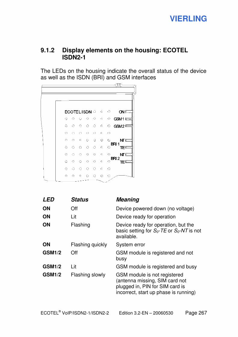
VIERLING
ECOTEL® VoIP/ISDN2-1/ISDN2-2 Edition 3.2-EN – 20060530 Page 267
9.1.2 Display elements on the housing: ECOTEL ISDN2-1
The LEDs on the housing indicate the overall status of the device as well as the ISDN (BRI) and GSM interfaces
LED Status Meaning
ON Off Device powered down (no voltage)
ON Lit Device ready for operation
ON Flashing Device ready for operation, but the basic setting for S0-TE or S0-NT is not available.
ON Flashing quickly System error
GSM1/2 Off GSM module is registered and not busy
GSM1/2 Lit GSM module is registered and busy
GSM1/2 Flashing slowly GSM module is not registered (antenna missing, SIM card not plugged in, PIN for SIM card is incorrect, start up phase is running)
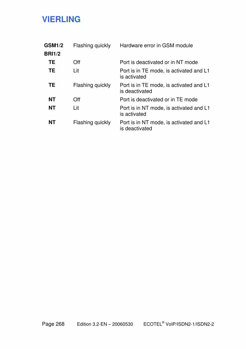
VIERLING
Page 268 Edition 3.2-EN – 20060530 ECOTEL® VoIP/ISDN2-1/ISDN2-2
GSM1/2 Flashing quickly Hardware error in GSM module
BRI1/2
TE Off Port is deactivated or in NT mode
TE Lit Port is in TE mode, is activated and L1 is activated
TE Flashing quickly Port is in TE mode, is activated and L1 is deactivated
NT Off Port is deactivated or in TE mode
NT Lit Port is in NT mode, is activated and L1 is activated
NT Flashing quickly Port is in NT mode, is activated and L1 is deactivated
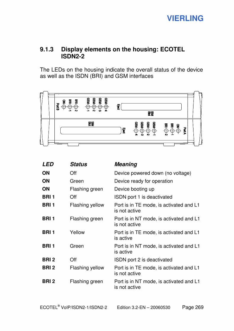
VIERLING
ECOTEL® VoIP/ISDN2-1/ISDN2-2 Edition 3.2-EN – 20060530 Page 269
9.1.3 Display elements on the housing: ECOTEL ISDN2-2
The LEDs on the housing indicate the overall status of the device as well as the ISDN (BRI) and GSM interfaces
LED Status Meaning
ON Off Device powered down (no voltage)
ON Green Device ready for operation
ON Flashing green Device booting up
BRI 1 Off ISDN port 1 is deactivated
BRI 1 Flashing yellow Port is in TE mode, is activated and L1 is not active
BRI 1 Flashing green Port is in NT mode, is activated and L1 is not active
BRI 1 Yellow Port is in TE mode, is activated and L1 is active
BRI 1 Green Port is in NT mode, is activated and L1 is active
BRI 2 Off ISDN port 2 is deactivated
BRI 2 Flashing yellow Port is in TE mode, is activated and L1 is not active
BRI 2 Flashing green Port is in NT mode, is activated and L1 is not active
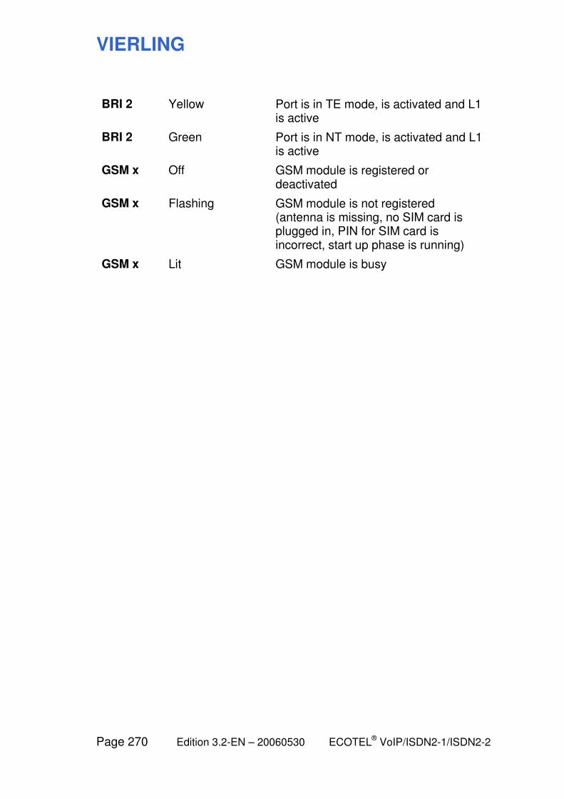
VIERLING
Page 270 Edition 3.2-EN – 20060530 ECOTEL® VoIP/ISDN2-1/ISDN2-2
BRI 2 Yellow Port is in TE mode, is activated and L1 is active
BRI 2 Green Port is in NT mode, is activated and L1 is active
GSM x Off GSM module is registered or deactivated
GSM x Flashing GSM module is not registered (antenna is missing, no SIM card is plugged in, PIN for SIM card is incorrect, start up phase is running)
GSM x Lit GSM module is busy
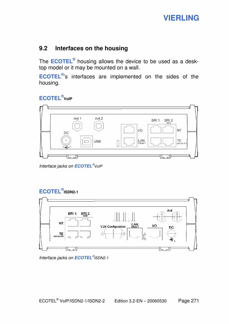
VIERLING
ECOTEL® VoIP/ISDN2-1/ISDN2-2 Edition 3.2-EN – 20060530 Page 271
9.2 Interfaces on the housing
The ECOTEL® housing allows the device to be used as a desk-
top model or it may be mounted on a wall.
ECOTEL®’s interfaces are implemented on the sides of the
housing.
ECOTEL®
VoIP
Interface jacks on ECOTEL®VoIP
ECOTEL®
ISDN2-1
Interface jacks on ECOTEL®ISDN2-1
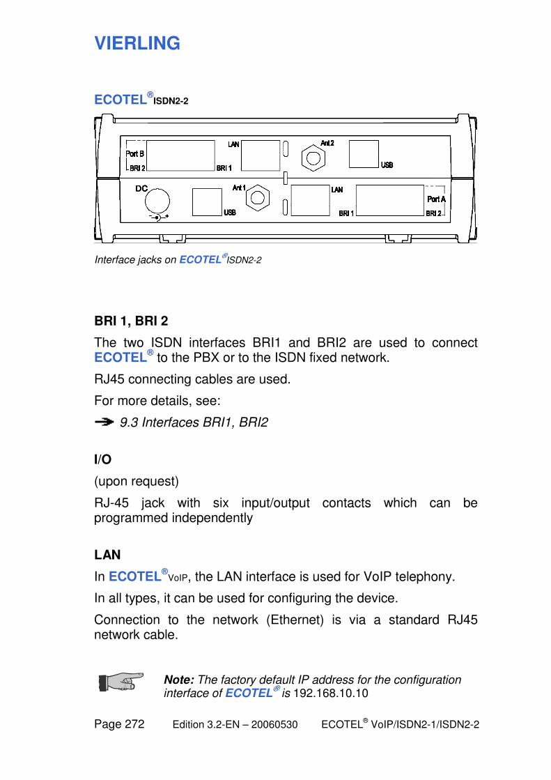
VIERLING
Page 272 Edition 3.2-EN – 20060530 ECOTEL® VoIP/ISDN2-1/ISDN2-2
ECOTEL®
ISDN2-2
Interface jacks on ECOTEL®ISDN2-2
BRI 1, BRI 2
The two ISDN interfaces BRI1 and BRI2 are used to connect ECOTEL
® to the PBX or to the ISDN fixed network.
RJ45 connecting cables are used.
For more details, see:
9.3 Interfaces BRI1, BRI2
I/O
(upon request)
RJ-45 jack with six input/output contacts which can be programmed independently
LAN
In ECOTEL®
VoIP, the LAN interface is used for VoIP telephony.
In all types, it can be used for configuring the device.
Connection to the network (Ethernet) is via a standard RJ45 network cable.
Note: The factory default IP address for the configuration interface of ECOTEL
® is 192.168.10.10
VIERLING
ECOTEL® VoIP/ISDN2-1/ISDN2-2 Edition 3.2-EN – 20060530 Page 273
USB (not in ECOTEL®
ISDN2-1 !)
The USB interface (type B) is used to configure the device.
It is connected via a standard USB cable.
V.24 (only in ECOTEL®
ISDN2-1 !)
The serial interface V.24 (RS232) is used to configure the device.
It is connected via a standard serial cable.
DC
The supplied power supply is connected to the DC jack of ECOTEL
®.
Warning: The guarantee for ECOTEL® is nullified if you
use a power supply which is not approved by VIERLING!
Different ECOTEL® types need different power supplies
since their power consumption is different!
Ant 1, Ant 2
Connectors for GSM antennas. On ECOTEL®
ISDN2-1, the left jack is Ant 1 and the right jack is Ant 2.
For additional information, see:
9.4 Antennas
SIM 1, SIM 2
In ECOTEL®
ISDN2-1: Slots for SIM cards.
VIERLING
Page 274 Edition 3.2-EN – 20060530 ECOTEL® VoIP/ISDN2-1/ISDN2-2
SIM Slot 1, SIM Slot 2
In ECOTEL®
VoIP, ECOTEL®
ISDN2-2: Slots for SIM cardholders. See the following section for more details:
9.5 SIM cardholder installation
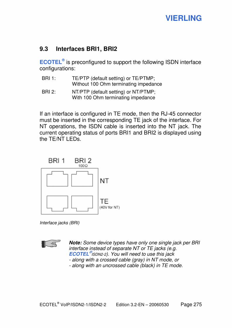
VIERLING
ECOTEL® VoIP/ISDN2-1/ISDN2-2 Edition 3.2-EN – 20060530 Page 275
9.3 Interfaces BRI1, BRI2
ECOTEL® is preconfigured to support the following ISDN interface
configurations:
BRI 1: TE/PTP (default setting) or TE/PTMP; Without 100 Ohm terminating impedance
BRI 2: NT/PTP (default setting) or NT/PTMP; With 100 Ohm terminating impedance
If an interface is configured in TE mode, then the RJ-45 connector must be inserted in the corresponding TE jack of the interface. For NT operations, the ISDN cable is inserted into the NT jack. The current operating status of ports BRI1 and BRI2 is displayed using the TE/NT LEDs.
Interface jacks (BRI)
Note: Some device types have only one single jack per BRI interface instead of separate NT or TE jacks (e.g. ECOTEL
®ISDN2-2). You will need to use this jack
- along with a crossed cable (gray) in NT mode, or - along with an uncrossed cable (black) in TE mode.
VIERLING
Page 276 Edition 3.2-EN – 20060530 ECOTEL® VoIP/ISDN2-1/ISDN2-2
Note: Improperly connected ISDN lines cannot damage the ISDN interfaces. Prerequisite: The ISDN terminal device that is connected must conform to TBR 3/TBR 3A1.
In rare instances, plug positions can deviate from the schematic shown here due to faulty wiring. In such a case, the wiring should be corrected.
Hub function during power outages
If the ECOTEL® controller or the power supply should fail, then
the BRI1 and BRI2 ports are automatically connected with each other. In the event of failure when utilizing ECOTEL
® as a least
cost router (ECOTEL® is connected via the BRI1 port to the fixed
network and via BRI2 to the PBX), the cost-saving function will fail. However, telephone calls can still be made over this connection.
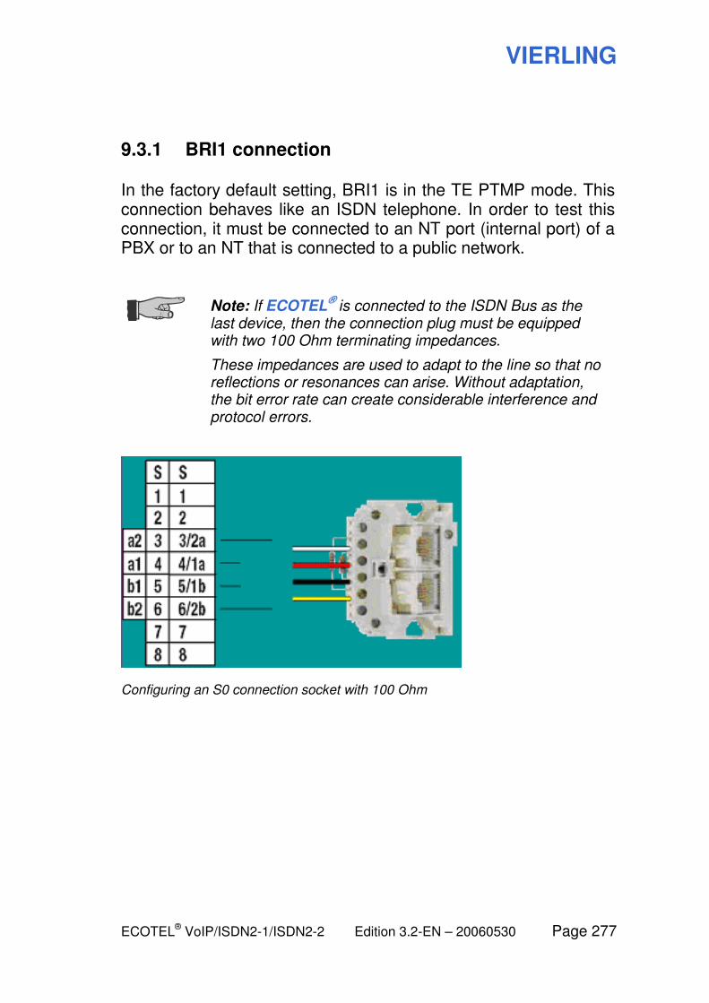
VIERLING
ECOTEL® VoIP/ISDN2-1/ISDN2-2 Edition 3.2-EN – 20060530 Page 277
9.3.1 BRI1 connection
In the factory default setting, BRI1 is in the TE PTMP mode. This connection behaves like an ISDN telephone. In order to test this connection, it must be connected to an NT port (internal port) of a PBX or to an NT that is connected to a public network.
Note: If ECOTEL
® is connected to the ISDN Bus as the
last device, then the connection plug must be equipped with two 100 Ohm terminating impedances.
These impedances are used to adapt to the line so that no reflections or resonances can arise. Without adaptation, the bit error rate can create considerable interference and protocol errors.
Configuring an S0 connection socket with 100 Ohm
VIERLING
Page 278 Edition 3.2-EN – 20060530 ECOTEL® VoIP/ISDN2-1/ISDN2-2
9.3.2 BRI2 connection
The BRI2 connection is set to the NT PTP mode at the factory and configured with a 100 Ohm terminating impedance. This connection behaves like an internal port of an ISDN PBX. This port is suitable for connecting ISDN telephones. Please be aware that ECOTEL
® does not supply power to the terminal devices that
are connected to it. Thus, telephones that are connected must have their own source of power, e.g. a suitable power supply unit.
Alternatively, devices connected to the bus can be supplied by a 40 V power supply unit (order no. 47591.359) which is available as an accessory. In this case, the S0 supply is plugged into the TE jack of the BRI2 connection.
VIERLING
ECOTEL® VoIP/ISDN2-1/ISDN2-2 Edition 3.2-EN – 20060530 Page 279
9.4 Antennas
Depending on the device type, ECOTEL® has either one or two
antenna connectors.
The antennas are not included. You can purchase the antennas from a dealer. The dealer should also help you to pick the best antenna for your current installation (depending on the installation site, the current field strength, frequency etc.). Depending on the received field strength of the GSM signal, you can use a mini-antenna, rod antenna or other directional antenna.
Antenna adapters from SNA to FME are included with the device. This means you can also connect antennas with FME connectors to ECOTEL
®.
Antenna installation
During installation, care must be taken that the antenna base is grounded (usually the mounting bracket). Grounding improves antenna reception. At the same time, the antenna is indirectly protected from the effects of lightening. Lightening which strikes in the vicinity could otherwise induce very high voltages in the antenna that would destroy ECOTEL
®. If the antenna is installed
directly on a roof, then a surge protector should also be installed. Information in this regard can be found in the antenna assembly instructions.
You can determine the current field strength at the installation site using the configuration software provided for ECOTEL
® (Firmware
Tools module).
Antenna connections
In the variant with two GSM modules, connect the antennas to connectors Ant 1 and Ant 2.
Variants with more than two GSM modules have built-in antenna splitters which connect a maximum of four GSM modules to the Ant 1 or Ant 2 connector. Ant 1 supplies GSM modules 1 to 4 and Ant 2 GSM modules 5 to 8.
VIERLING
Page 280 Edition 3.2-EN – 20060530 ECOTEL® VoIP/ISDN2-1/ISDN2-2
9.5 SIM cardholder installation
To operate the ECOTEL®, you will need SIM cards from one or
more GSM providers in order to be able to route calls and SMS messages to GSM networks.
Installation types
ECOTEL®
ISDN2-1 has simple card slots in the housing, each for one single SIM card.
In ECOTEL®
VoIP and ECOTEL®
ISDN2-2, several SIM cards are installed on a PCMCIA SIM cardholder which is then inserted into one of the cardholder slots (see further below).
If ECOTEL®
VoIP or ECOTEL®
ISDN2-2 is to be operated using an external SIM server instead of locally installed SIM cards, a SIM emulation board must be inserted into the cardholder slot. This board will connect to the SIM server and emulate the SIM cards installed there with respect to the ECOTEL
®. For further
information, please see:
9.5.4 SIM emulation board
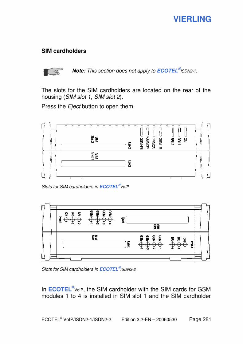
VIERLING
ECOTEL® VoIP/ISDN2-1/ISDN2-2 Edition 3.2-EN – 20060530 Page 281
SIM cardholders
Note: This section does not apply to ECOTEL
®ISDN2-1.
The slots for the SIM cardholders are located on the rear of the housing (SIM slot 1, SIM slot 2).
Press the Eject button to open them.
Slots for SIM cardholders in ECOTEL®VoIP
Slots for SIM cardholders in ECOTEL®ISDN2-2
In ECOTEL®
VoIP, the SIM cardholder with the SIM cards for GSM modules 1 to 4 is installed in SIM slot 1 and the SIM cardholder
VIERLING
Page 282 Edition 3.2-EN – 20060530 ECOTEL® VoIP/ISDN2-1/ISDN2-2
with the SIM cards for GSM modules 5 to 8 is installed in SIM slot 2.
In ECOTEL®
ISDN2-2, there is one SIM cardholder for each of the semi-devices which holds the SIM cards for the GSM modules 1 to 4 of this semi-device.
A PCMCIA cardholder can hold up to 32 SIM cards. This means that it is possible to have up to 8 different SIM cards for each of the four GSM modules.
The cardholders are not included.
Warning: Since the SIM cards and cardholders are electronic components, they can be damaged or destroyed by electrostatic discharge. To prevent this, you should install the SIM cards at an ESD workstation.
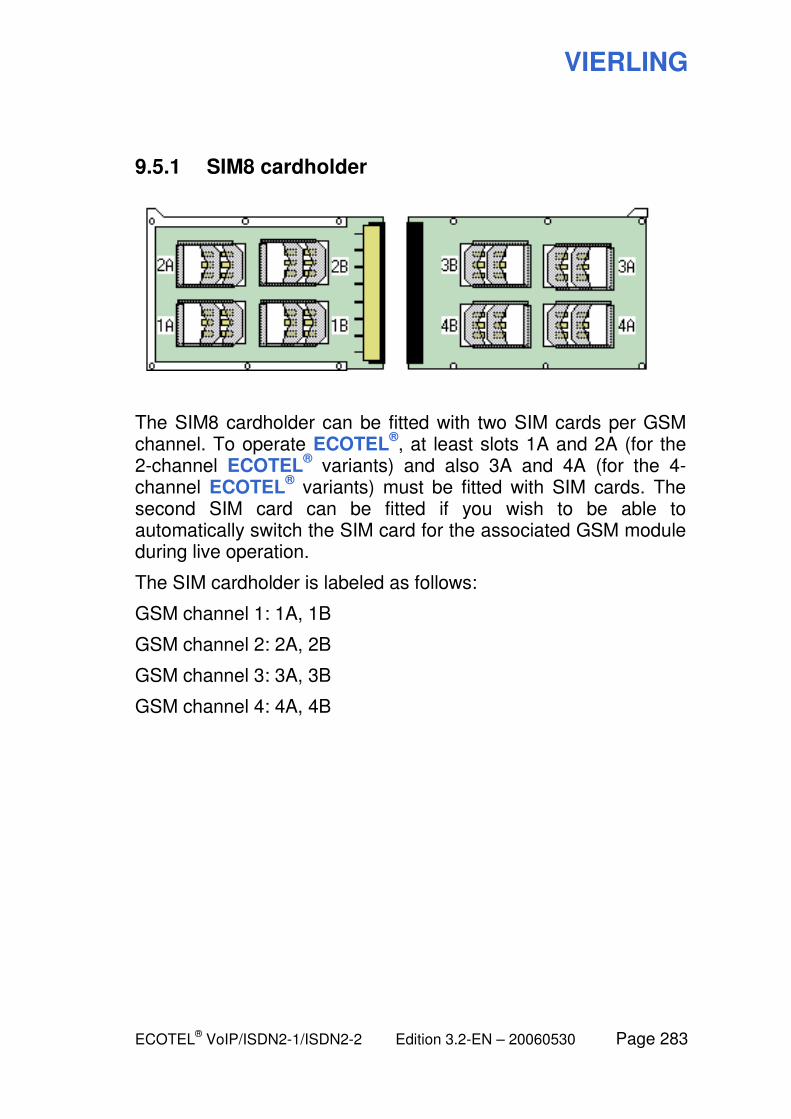
VIERLING
ECOTEL® VoIP/ISDN2-1/ISDN2-2 Edition 3.2-EN – 20060530 Page 283
9.5.1 SIM8 cardholder
The SIM8 cardholder can be fitted with two SIM cards per GSM channel. To operate ECOTEL
®, at least slots 1A and 2A (for the
2-channel ECOTEL® variants) and also 3A and 4A (for the 4-
channel ECOTEL® variants) must be fitted with SIM cards. The
second SIM card can be fitted if you wish to be able to automatically switch the SIM card for the associated GSM module during live operation.
The SIM cardholder is labeled as follows:
GSM channel 1: 1A, 1B
GSM channel 2: 2A, 2B
GSM channel 3: 3A, 3B
GSM channel 4: 4A, 4B
VIERLING
Page 284 Edition 3.2-EN – 20060530 ECOTEL® VoIP/ISDN2-1/ISDN2-2
9.5.2 SIM16 cardholder
The SIM16 cardholder can be fitted with four SIM cards for each GSM channel. Install the SIM cards as follows:
– Fit the cover of the SIM16 cardholder (printed inside and
outside) with the SIM cards (contact surface facing up).
– Place the printed circuit board on the SIM cards and screw
it to the cover.
– Fit the lower part of the SIM16 cardholder (printed inside
only) with the SIM cards (contact surface facing up).
– Screw the pre-mounted unit consisting of the lower part
and the printed circuit board to the lower part.
The SIM cardholder is labeled as follows:
GSM channel 1: 1A, 1B, 1C, 1D
GSM channel 2: 2A, 2B, 2C, 2D
GSM channel 3: 3A, 3B, 3C, 3D
GSM channel 4: 4A, 4B, 4C, 4D

VIERLING
ECOTEL® VoIP/ISDN2-1/ISDN2-2 Edition 3.2-EN – 20060530 Page 285
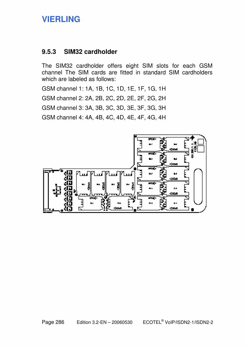
VIERLING
Page 286 Edition 3.2-EN – 20060530 ECOTEL® VoIP/ISDN2-1/ISDN2-2
9.5.3 SIM32 cardholder
The SIM32 cardholder offers eight SIM slots for each GSM channel The SIM cards are fitted in standard SIM cardholders which are labeled as follows:
GSM channel 1: 1A, 1B, 1C, 1D, 1E, 1F, 1G, 1H
GSM channel 2: 2A, 2B, 2C, 2D, 2E, 2F, 2G, 2H
GSM channel 3: 3A, 3B, 3C, 3D, 3E, 3F, 3G, 3H
GSM channel 4: 4A, 4B, 4C, 4D, 4E, 4F, 4G, 4H
VIERLING
ECOTEL® VoIP/ISDN2-1/ISDN2-2 Edition 3.2-EN – 20060530 Page 287
9.5.4 SIM emulation board
To operate the SIM emulation board, please make the following settings in the SIM Management module under SIM Cardholder.
Normal operation: Usage of external SIM cards
Under SIM slot 1 and/or SIM slot 2 (depending on the configuration), select the entry SIM emulation board.
Under IP address, enter the IP address of the SIM server on which the SIM cards to be used are located.
Special case: Usage of the SIM slots on the SIM emulation board
On the SIM emulation board, there are slots for SIM cards which can be used, for example, as a temporary replacement for the SIM server.
ECOTEL® does not use these SIM cards automatically. It must be
configured to do so:
Under SIM slot 1 and/or SIM slot 2 (depending on the configuration), select the entry SIM 8 board (not SIM emulation board!). Configure it like a normal SIM 8 cardholder that only has slots 1B, 2B, 3B and 4B.
VIERLING
Page 288 Edition 3.2-EN – 20060530 ECOTEL® VoIP/ISDN2-1/ISDN2-2
9.6 Peculiarities of ECOTEL ISDN2-2 and other models with a dual design
Note: This section applies to the following ECOTEL
®
models: ECOTEL
®ISDN2-2xx
ECOTEL®ISDN2-14x
Certain ECOTEL® models (see above) have a different design
that needs to be taken into account. In this manual, we refer to ECOTEL
®ISDN2-2 when we need to reference such models.
Two devices in one housing
This design basically involves two ECOTEL® devices in a single
housing.
Almost all of the parts (including the interface jacks) are present in duplicate (exception: power supply).
Important: When you are setting up and configuring ECOTEL
®ISDN2-2, you should always treat it like two
separate devices!
In particular, you should:
– Create two separate devices in the Service Gear module
– Connect each semi-device separately to the desired
networks (ISDN, PBX, LAN, etc.)
– Configure each semi-device separately via the respective
interface jack
– During any uploads and downloads, make sure that you
are connected to the correct semi-device
VIERLING
ECOTEL® VoIP/ISDN2-1/ISDN2-2 Edition 3.2-EN – 20060530 Page 289
Wiring the BRI interfaces
ECOTEL®
ISDN2-2 has only one type of jack for the BRI1 and BRI2 interfaces. A distinction between TE jack and NT jack is realized alternatively using different connecting cables.
Use the following connecting cables:
– For use as a TE jack:
Uncrossed cable (black)
– For use as an NT jack:
Crossed cable (gray)
VIERLING
Page 290 Edition 3.2-EN – 20060530 ECOTEL® VoIP/ISDN2-1/ISDN2-2
10 Technical Details
VIERLING
ECOTEL® VoIP/ISDN2-1/ISDN2-2 Edition 3.2-EN – 20060530 Page 291
10.1 Wave files for speech announcements
This table lists the file names and contents of all available WAVE files for voice announcements in ECOTEL
®.
The prefix XXX in the file name stands for the country code. Files in different languages with the same content have the same number but different prefixes. Files with the SYS prefix are common to all languages.
If ECOTEL® needs a certain wave file, it will first look for the file with the country code for the currently set language. If it does not find this file, then it will use the SYS variant instead if it exists.
The letter a stands for A-Law coding.
DTMF tones 1000 ms
SYS000a.wav DTMF D (1000 ms)
SYS001a.wav DTMF 1 (1000 ms)
SYS002a.wav DTMF 2 (1000 ms)
SYS003a.wav DTMF 3 (1000 ms)
SYS004a.wav DTMF 4 (1000 ms)
SYS005a.wav DTMF 5 (1000 ms)
SYS006a.wav DTMF 6 (1000 ms)
SYS007a.wav DTMF 7 (1000 ms)
SYS008a.wav DTMF 8 (1000 ms)
SYS009a.wav DTMF 9 (1000 ms)
SYS010a.wav DTMF 0 (1000 ms)
SYS011a.wav DTMF * (1000 ms)
SYS012a.wav DTMF # (1000 ms)
SYS013a.wav DTMF A (1000 ms)
SYS014a.wav DTMF B (1000 ms)
SYS015a.wav DTMF C (1000 ms)
Tones
VIERLING
Page 292 Edition 3.2-EN – 20060530 ECOTEL® VoIP/ISDN2-1/ISDN2-2
SYS016a.wav Sinewave 425 Hz Dial tone
SYS017a.wav Sinewave 425 Hz Busy signal
SYS018a.wav Sinewave sweep 300 -3400 Hz
Speech phrases
XXX032a.wav The phone number in memory location
XXX033a.wav is
XXX034a.wav has been deleted
XXX035a.wav Number
XXX036a.wav Memory number
XXX037a.wav The number is busy
XXX038a.wav If you want another extension, please dial
XXX039a.wav The call is completed
XXX040a.wav This is mobile number
XXX041a.wav Please enter the extension
XXX042a.wav The entry is confirmed
XXX043a.wav The entry is wrong
XXX044a.wav Alarm
XXX045a.wav Please wait
XXX046a.wav Please wait for a connection
XXX047a.wav The call could not be completed
XXX048a.wav Zero
XXX049a.wav One
XXX050a.wav Two
XXX051a.wav Three
XXX052a.wav Four
XXX053a.wav Five
XXX054a.wav Six
XXX055a.wav Seven
XXX056a.wav Eight
XXX057a.wav Nine
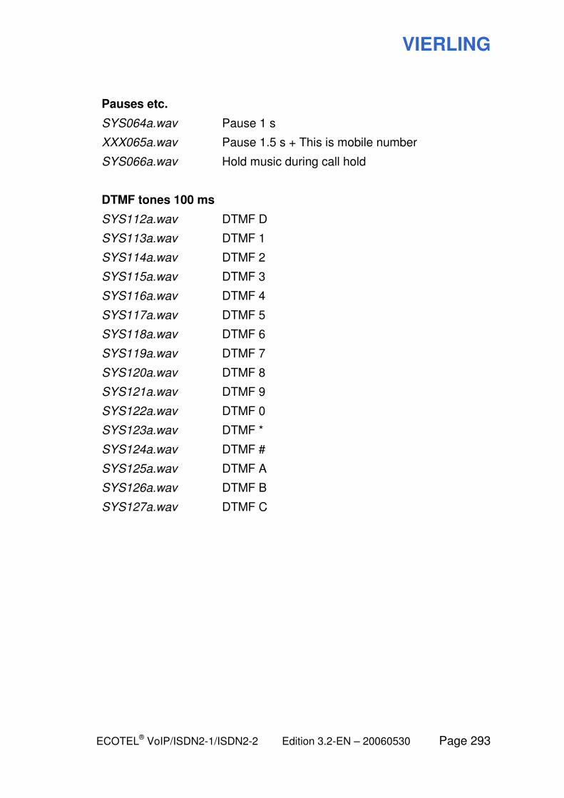
VIERLING
ECOTEL® VoIP/ISDN2-1/ISDN2-2 Edition 3.2-EN – 20060530 Page 293
Pauses etc.
SYS064a.wav Pause 1 s
XXX065a.wav Pause 1.5 s + This is mobile number
SYS066a.wav Hold music during call hold
DTMF tones 100 ms
SYS112a.wav DTMF D
SYS113a.wav DTMF 1
SYS114a.wav DTMF 2
SYS115a.wav DTMF 3
SYS116a.wav DTMF 4
SYS117a.wav DTMF 5
SYS118a.wav DTMF 6
SYS119a.wav DTMF 7
SYS120a.wav DTMF 8
SYS121a.wav DTMF 9
SYS122a.wav DTMF 0
SYS123a.wav DTMF *
SYS124a.wav DTMF #
SYS125a.wav DTMF A
SYS126a.wav DTMF B
SYS127a.wav DTMF C
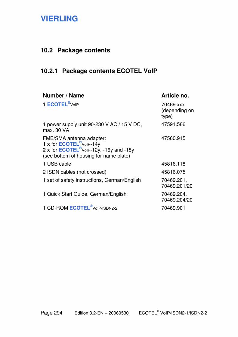
VIERLING
Page 294 Edition 3.2-EN – 20060530 ECOTEL® VoIP/ISDN2-1/ISDN2-2
10.2 Package contents
10.2.1 Package contents ECOTEL VoIP
Number / Name Article no.
1 ECOTEL®
VoIP 70469.xxx (depending on type)
1 power supply unit 90-230 V AC / 15 V DC, max. 30 VA
47591.586
FME/SMA antenna adapter: 1 x for ECOTEL
®VoIP-14y
2 x for ECOTEL®
VoIP-12y, -16y and -18y (see bottom of housing for name plate)
47560.915
1 USB cable 45816.118
2 ISDN cables (not crossed) 45816.075
1 set of safety instructions, German/English 70469.201, 70469.201/20
1 Quick Start Guide, German/English 70469.204, 70469.204/20
1 CD-ROM ECOTEL®
VoIP/ISDN2-2 70469.901
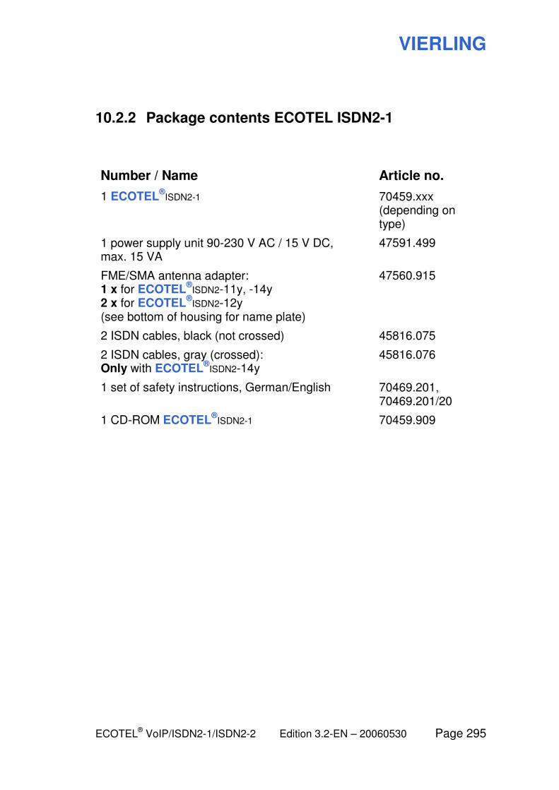
VIERLING
ECOTEL® VoIP/ISDN2-1/ISDN2-2 Edition 3.2-EN – 20060530 Page 295
10.2.2 Package contents ECOTEL ISDN2-1
Number / Name Article no.
1 ECOTEL®
ISDN2-1 70459.xxx (depending on type)
1 power supply unit 90-230 V AC / 15 V DC, max. 15 VA
47591.499
FME/SMA antenna adapter: 1 x for ECOTEL
®ISDN2-11y, -14y
2 x for ECOTEL®
ISDN2-12y (see bottom of housing for name plate)
47560.915
2 ISDN cables, black (not crossed) 45816.075
2 ISDN cables, gray (crossed): Only with ECOTEL
®ISDN2-14y
45816.076
1 set of safety instructions, German/English 70469.201, 70469.201/20
1 CD-ROM ECOTEL®
ISDN2-1 70459.909

VIERLING
Page 296 Edition 3.2-EN – 20060530 ECOTEL® VoIP/ISDN2-1/ISDN2-2
10.2.3 Package contents ECOTEL ISDN2-2
Number / Name Article no.
1 ECOTEL®
ISDN2-2 70469.xxx (depending on type)
1 power supply unit 90-230 V AC / 15 V DC, max. 30 VA
47591.586
2 FME/SMA antenna adapters 47560.915
1 USB cable 45816.118
2 ISDN cables black (not crossed) 45816.075
2 ISDN cables gray (crossed) 45816.076
1 set of safety instructions, German/English 70469.203, 70469.203/20
1 CD-ROM ECOTEL®
VoIP/ISDN2-2 70469.901
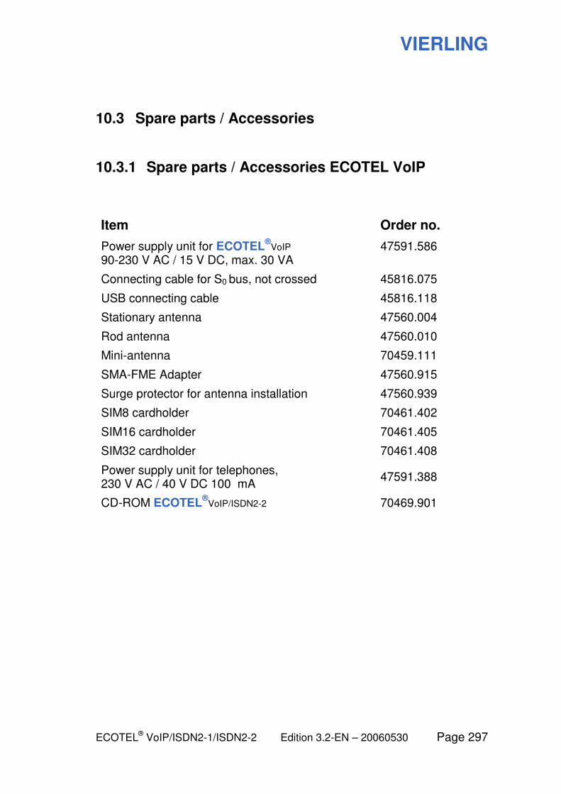
VIERLING
ECOTEL® VoIP/ISDN2-1/ISDN2-2 Edition 3.2-EN – 20060530 Page 297
10.3 Spare parts / Accessories
10.3.1 Spare parts / Accessories ECOTEL VoIP
Item Order no.
Power supply unit for ECOTEL®
VoIP 90-230 V AC / 15 V DC, max. 30 VA
47591.586
Connecting cable for S0 bus, not crossed 45816.075
USB connecting cable 45816.118
Stationary antenna 47560.004
Rod antenna 47560.010
Mini-antenna 70459.111
SMA-FME Adapter 47560.915
Surge protector for antenna installation 47560.939
SIM8 cardholder 70461.402
SIM16 cardholder 70461.405
SIM32 cardholder 70461.408
Power supply unit for telephones, 230 V AC / 40 V DC 100 mA
47591.388
CD-ROM ECOTEL®
VoIP/ISDN2-2 70469.901
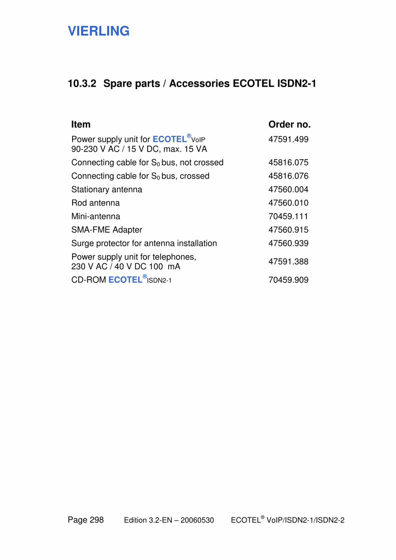
VIERLING
Page 298 Edition 3.2-EN – 20060530 ECOTEL® VoIP/ISDN2-1/ISDN2-2
10.3.2 Spare parts / Accessories ECOTEL ISDN2-1
Item Order no.
Power supply unit for ECOTEL®
VoIP 90-230 V AC / 15 V DC, max. 15 VA
47591.499
Connecting cable for S0 bus, not crossed 45816.075
Connecting cable for S0 bus, crossed 45816.076
Stationary antenna 47560.004
Rod antenna 47560.010
Mini-antenna 70459.111
SMA-FME Adapter 47560.915
Surge protector for antenna installation 47560.939
Power supply unit for telephones, 230 V AC / 40 V DC 100 mA
47591.388
CD-ROM ECOTEL®
ISDN2-1 70459.909
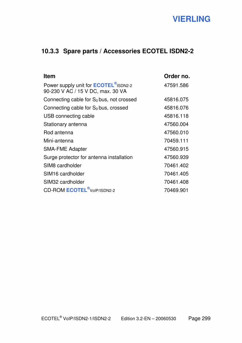
VIERLING
ECOTEL® VoIP/ISDN2-1/ISDN2-2 Edition 3.2-EN – 20060530 Page 299
10.3.3 Spare parts / Accessories ECOTEL ISDN2-2
Item Order no.
Power supply unit for ECOTEL®
ISDN2-2 90-230 V AC / 15 V DC, max. 30 VA
47591.586
Connecting cable for S0 bus, not crossed 45816.075
Connecting cable for S0 bus, crossed 45816.076
USB connecting cable 45816.118
Stationary antenna 47560.004
Rod antenna 47560.010
Mini-antenna 70459.111
SMA-FME Adapter 47560.915
Surge protector for antenna installation 47560.939
SIM8 cardholder 70461.402
SIM16 cardholder 70461.405
SIM32 cardholder 70461.408
CD-ROM ECOTEL®
VoIP/ISDN2-2 70469.901
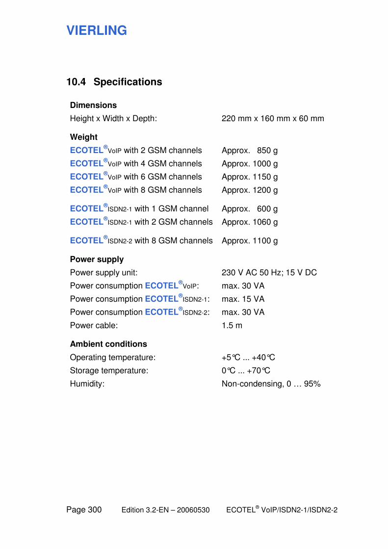
VIERLING
Page 300 Edition 3.2-EN – 20060530 ECOTEL® VoIP/ISDN2-1/ISDN2-2
10.4 Specifications
Dimensions
Height x Width x Depth: 220 mm x 160 mm x 60 mm
Weight
ECOTEL®
VoIP with 2 GSM channels Approx. 850 g
ECOTEL®
VoIP with 4 GSM channels Approx. 1000 g
ECOTEL®
VoIP with 6 GSM channels Approx. 1150 g
ECOTEL®
VoIP with 8 GSM channels Approx. 1200 g
ECOTEL
®ISDN2-1 with 1 GSM channel Approx. 600 g
ECOTEL®
ISDN2-1 with 2 GSM channels Approx. 1060 g
ECOTEL
®ISDN2-2 with 8 GSM channels Approx. 1100 g
Power supply
Power supply unit: 230 V AC 50 Hz; 15 V DC
Power consumption ECOTEL®
VoIP: max. 30 VA
Power consumption ECOTEL®
ISDN2-1: max. 15 VA
Power consumption ECOTEL®
ISDN2-2: max. 30 VA
Power cable: 1.5 m
Ambient conditions
Operating temperature: +5°C ... +40°C
Storage temperature: 0°C ... +70°C
Humidity: Non-condensing, 0 … 95%
VIERLING
ECOTEL® VoIP/ISDN2-1/ISDN2-2 Edition 3.2-EN – 20060530 Page 301
10.5 Maintenance and Warranty
ECOTEL® is maintenance free. Should any problems occur,
please contact your sales representative.
The warranty period is 24 months.
Repairs will be made within the warranty period without charge unless the device has been improperly operated.
VIERLING
Page 302 Edition 3.2-EN – 20060530 ECOTEL® VoIP/ISDN2-1/ISDN2-2
10.6 Conditions for using the software
Utilization rights: Program
With this software copy, VIERLING grants to you, as customer, utilization rights that are both non-assignable and non-exclusive and that do not expire. These stipulations also apply to any program changes or program extensions that may become necessary.
Utilization rights in this context mean:
The user may utilize this software on any available hardware. However, if the user changes the hardware being used, then the software in it must be deleted and removed.
Simultaneously storing the software, either electronically or physically, or using the software in more than one hardware device, is expressly prohibited. If the user desires to utilize the software simultaneously in several hardware configurations (for example among several employees), then it is necessary to purchase the corresponding number of program packages.
Utilization rights: User manual and operating instructions
All rights to the user manual and operating instructions, and in particular photo-technical reproduction rights, remain the property of VIERLING.
Liability
VIERLING is not liable for any damages, either direct or indirect, whether material or immaterial, that result from using this program, or from using the user manual or operating instructions.
Liability for data loss and for resulting damages is excluded within lawful limitations.
Changes
Any changes to these conditions and any collateral agreements must be in writing in order to be valid.
Ebermannstadt, 17.06.2005


