Download - uSD-1212 Adapter Board
1 The information contained herein is the exclusive property of AzureWave and shall not be distributed, reproduced, or disclosed in whole or in part without prior written permission of AzureWave.
uSD-1212 Adapter Board
for AW-AM281-uSD and AW-CM358-uSD
User Guide
Rev. G
(For Standard)
2 The information contained herein is the exclusive property of AzureWave and shall not be distributed, reproduced, or disclosed in whole or in part without prior written permission of AzureWave.
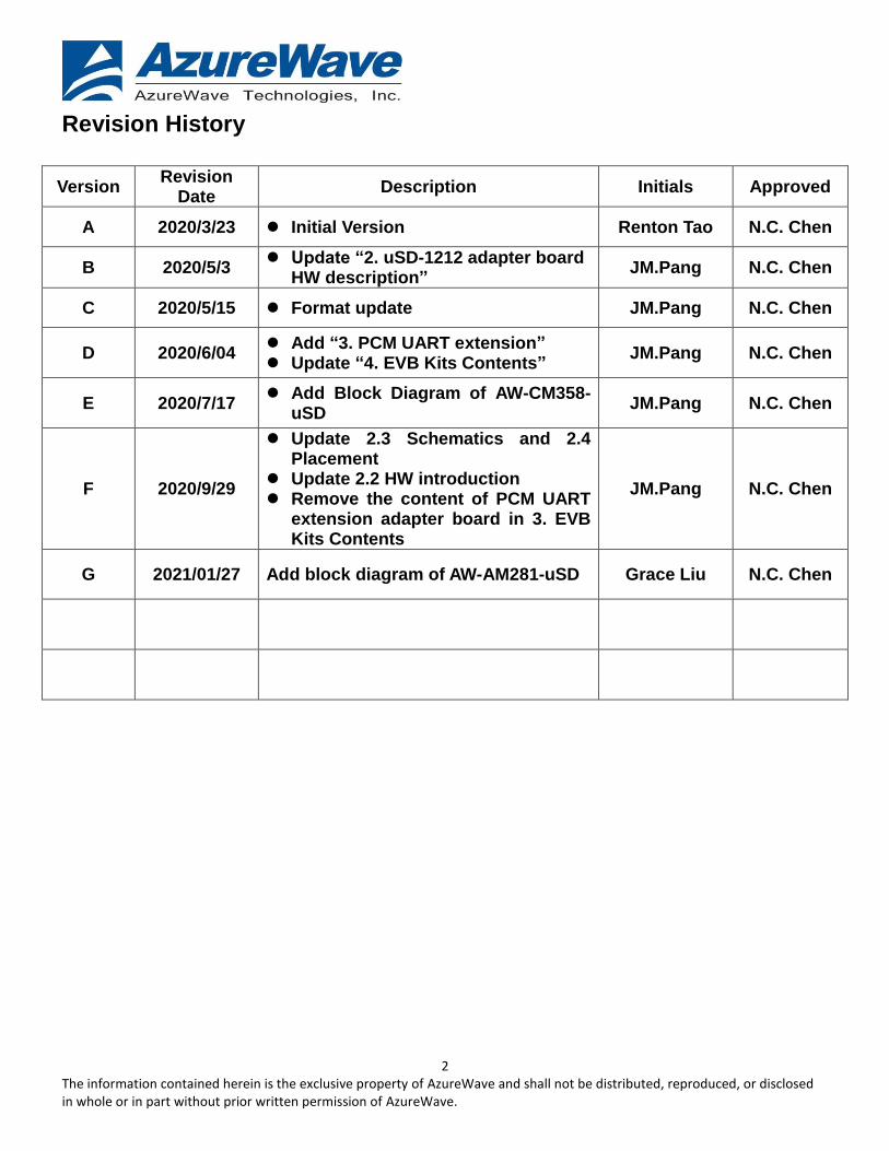
Revision History
Version Revision
Date Description Initials Approved
A 2020/3/23 Initial Version Renton Tao N.C. Chen
B 2020/5/3 Update “2. uSD-1212 adapter board
HW description” JM.Pang N.C. Chen
C 2020/5/15 Format update JM.Pang N.C. Chen
D 2020/6/04 Add “3. PCM UART extension”
Update “4. EVB Kits Contents” JM.Pang N.C. Chen
E 2020/7/17 Add Block Diagram of AW-CM358-
uSD JM.Pang N.C. Chen
F 2020/9/29
Update 2.3 Schematics and 2.4 Placement
Update 2.2 HW introduction Remove the content of PCM UART
extension adapter board in 3. EVB Kits Contents
JM.Pang N.C. Chen
G 2021/01/27 Add block diagram of AW-AM281-uSD Grace Liu N.C. Chen
3 The information contained herein is the exclusive property of AzureWave and shall not be distributed, reproduced, or disclosed in whole or in part without prior written permission of AzureWave.
Table of Content
1. Introduction .............................................................................................................................. 4
1.1 Supported I/O to host ................................................................................................................................ 4
1.2 Supported I/O signal level ......................................................................................................................... 4
1.3 Supported RF standards ........................................................................................................................... 4
2. uSD-1212 Adapter Board ......................................................................................................... 5
2.1 Block Diagram ............................................................................................................................................ 5
2.2 HW Description ........................................................................................................................................... 6
2.3 Schematics .................................................................................................................................................. 9
2.4 Placement.................................................................................................................................................. 12
3. EVB Kits Contents ................................................................................................................. 14
4 The information contained herein is the exclusive property of AzureWave and shall not be distributed, reproduced, or disclosed in whole or in part without prior written permission of AzureWave.
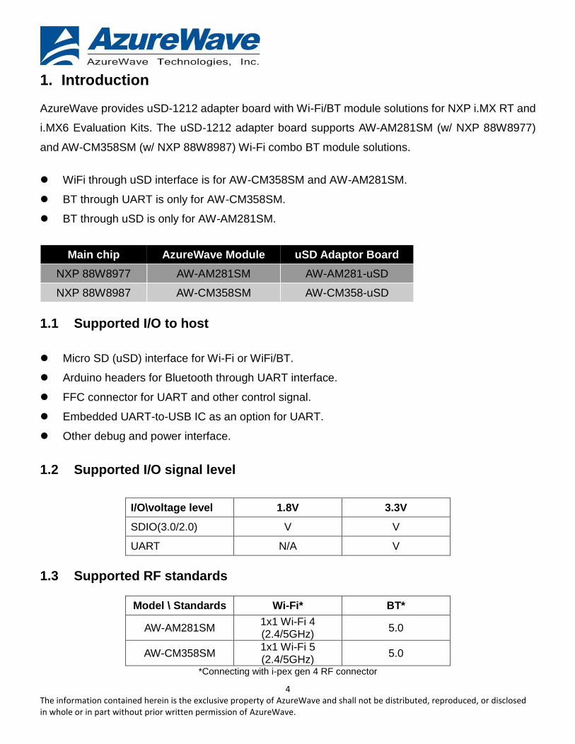
1. Introduction
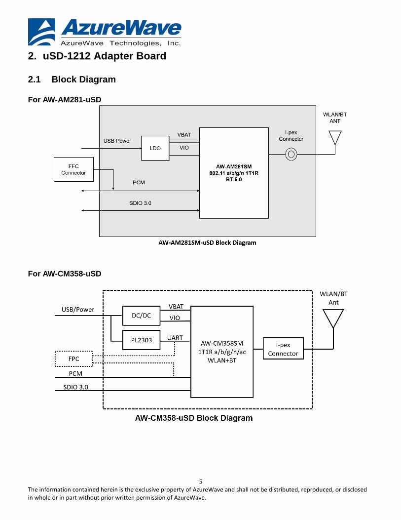
AzureWave provides uSD-1212 adapter board with Wi-Fi/BT module solutions for NXP i.MX RT and
i.MX6 Evaluation Kits. The uSD-1212 adapter board supports AW-AM281SM (w/ NXP 88W8977)
and AW-CM358SM (w/ NXP 88W8987) Wi-Fi combo BT module solutions.
WiFi through uSD interface is for AW-CM358SM and AW-AM281SM.
BT through UART is only for AW-CM358SM.
BT through uSD is only for AW-AM281SM.
Main chip AzureWave Module uSD Adaptor Board
NXP 88W8977 AW-AM281SM AW-AM281-uSD
NXP 88W8987 AW-CM358SM AW-CM358-uSD
1.1 Supported I/O to host
Micro SD (uSD) interface for Wi-Fi or WiFi/BT.
Arduino headers for Bluetooth through UART interface.
FFC connector for UART and other control signal.
Embedded UART-to-USB IC as an option for UART.
Other debug and power interface.
1.2 Supported I/O signal level
I/O\voltage level 1.8V 3.3V
SDIO(3.0/2.0) V V
UART N/A V
1.3 Supported RF standards
Model \ Standards Wi-Fi* BT*
AW-AM281SM 1x1 Wi-Fi 4 (2.4/5GHz)
5.0
AW-CM358SM 1x1 Wi-Fi 5 (2.4/5GHz)
5.0
*Connecting with i-pex gen 4 RF connector
5 The information contained herein is the exclusive property of AzureWave and shall not be distributed, reproduced, or disclosed in whole or in part without prior written permission of AzureWave.
2. uSD-1212 Adapter Board 2.1 Block Diagram For AW-AM281-uSD
For AW-CM358-uSD
6 The information contained herein is the exclusive property of AzureWave and shall not be distributed, reproduced, or disclosed in whole or in part without prior written permission of AzureWave.
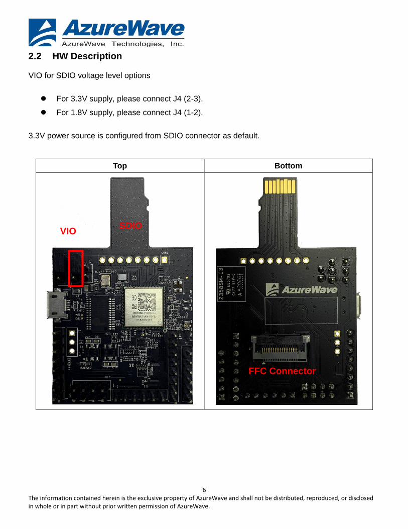
2.2 HW Description
VIO for SDIO voltage level options
For 3.3V supply, please connect J4 (2-3).
For 1.8V supply, please connect J4 (1-2).
3.3V power source is configured from SDIO connector as default.
Top Bottom
SDIO VIO
FFC Connector
7 The information contained herein is the exclusive property of AzureWave and shall not be distributed, reproduced, or disclosed in whole or in part without prior written permission of AzureWave.
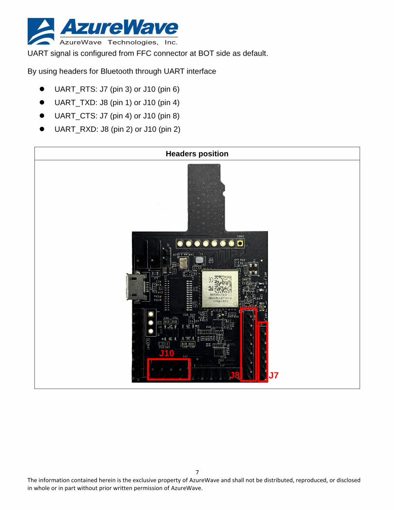
UART signal is configured from FFC connector at BOT side as default.
By using headers for Bluetooth through UART interface
UART_RTS: J7 (pin 3) or J10 (pin 6)
UART_TXD: J8 (pin 1) or J10 (pin 4)
UART_CTS: J7 (pin 4) or J10 (pin 8)
UART_RXD: J8 (pin 2) or J10 (pin 2)
Headers position
J8
J10
J7
8 The information contained herein is the exclusive property of AzureWave and shall not be distributed, reproduced, or disclosed in whole or in part without prior written permission of AzureWave.
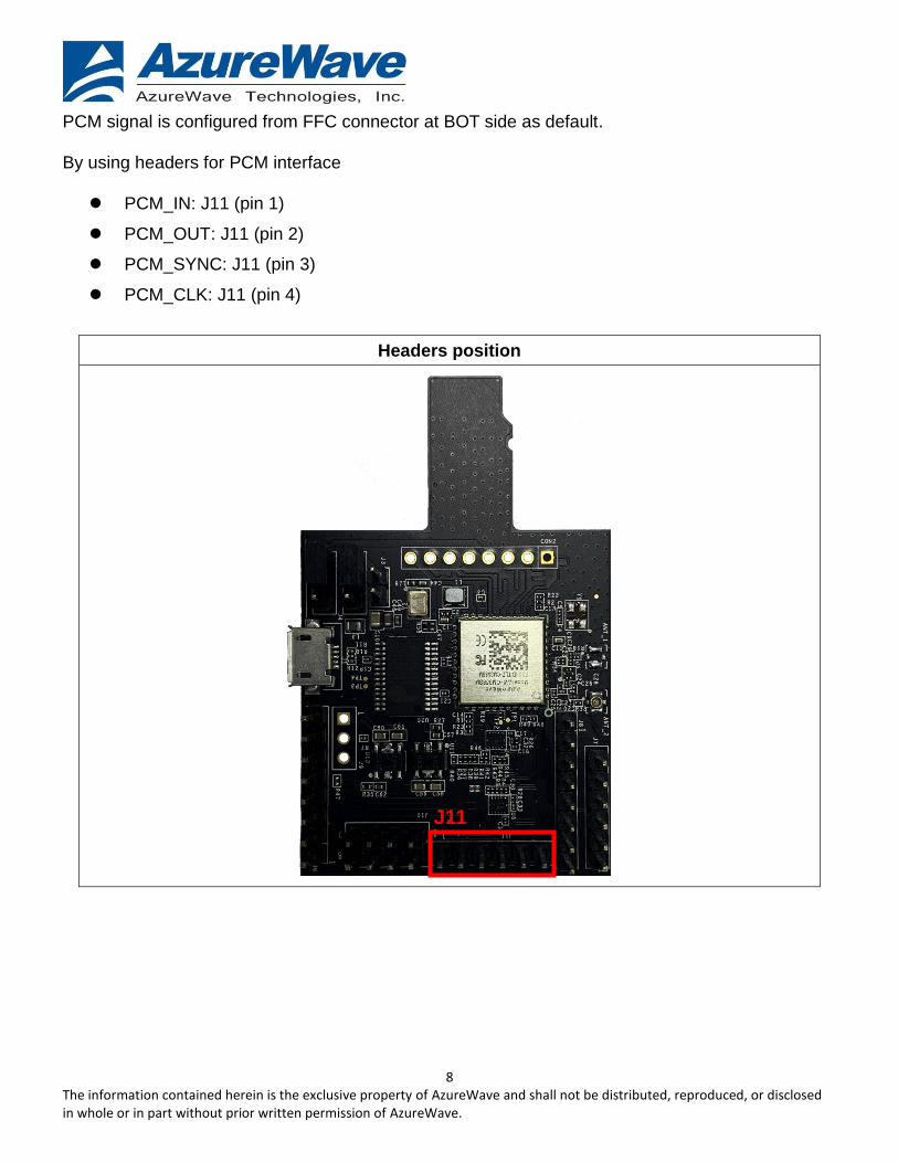
PCM signal is configured from FFC connector at BOT side as default.
By using headers for PCM interface
PCM_IN: J11 (pin 1)
PCM_OUT: J11 (pin 2)
PCM_SYNC: J11 (pin 3)
PCM_CLK: J11 (pin 4)
Headers position
J11
9 The information contained herein is the exclusive property of AzureWave and shall not be distributed, reproduced, or disclosed in whole or in part without prior written permission of AzureWave.
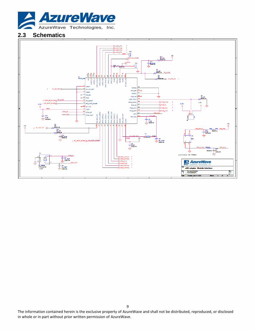
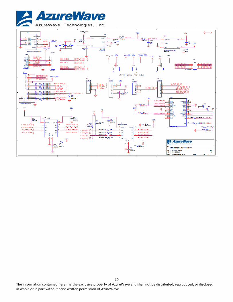
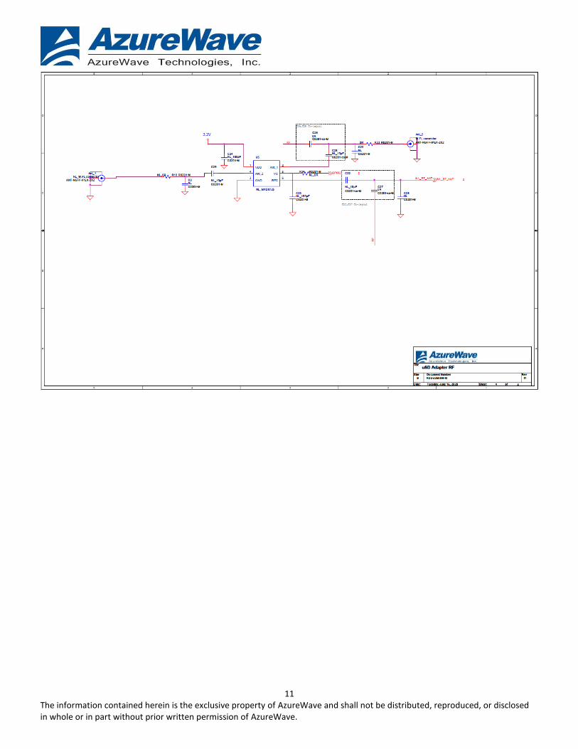
2.3 Schematics
10 The information contained herein is the exclusive property of AzureWave and shall not be distributed, reproduced, or disclosed in whole or in part without prior written permission of AzureWave.
11 The information contained herein is the exclusive property of AzureWave and shall not be distributed, reproduced, or disclosed in whole or in part without prior written permission of AzureWave.
12 The information contained herein is the exclusive property of AzureWave and shall not be distributed, reproduced, or disclosed in whole or in part without prior written permission of AzureWave.
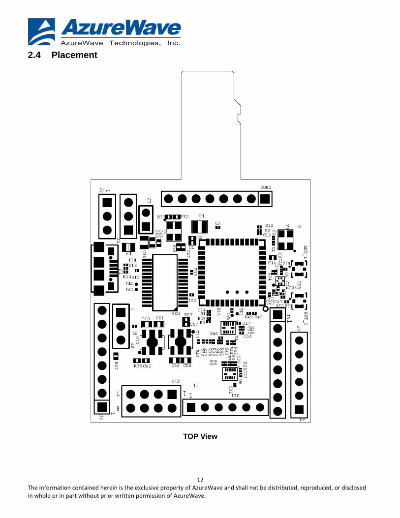
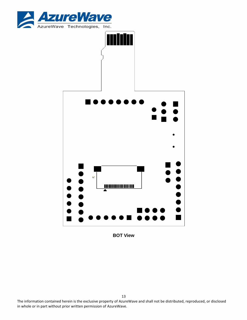
2.4 Placement
TOP View
13 The information contained herein is the exclusive property of AzureWave and shall not be distributed, reproduced, or disclosed in whole or in part without prior written permission of AzureWave.
BOT View
14 The information contained herein is the exclusive property of AzureWave and shall not be distributed, reproduced, or disclosed in whole or in part without prior written permission of AzureWave.
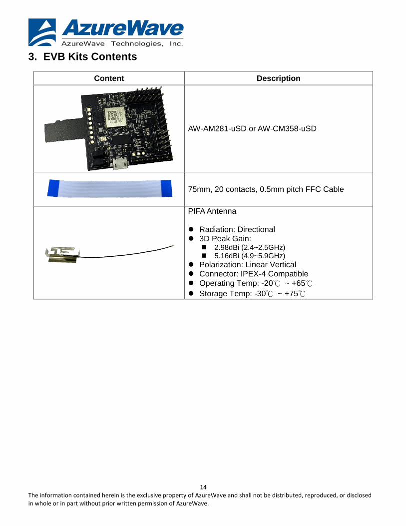
3. EVB Kits Contents
Content Description
AW-AM281-uSD or AW-CM358-uSD
75mm, 20 contacts, 0.5mm pitch FFC Cable
PIFA Antenna Radiation: Directional 3D Peak Gain:
2.98dBi (2.4~2.5GHz) 5.16dBi (4.9~5.9GHz)
Polarization: Linear Vertical Connector: IPEX-4 Compatible
Operating Temp: -20℃ ~ +65℃
Storage Temp: -30℃ ~ +75℃


