AN-49-005 Rev.: F (September 3, 2017) M163233 (R92330) File: AN-49-005(F).doc This document and its contents are the property of Mini-Circuits
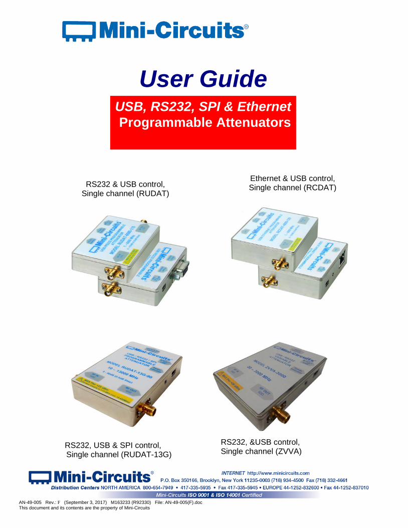
User Guide
RS232 & USB control, Single channel (RUDAT)
USB, RS232, SPI & Ethernet Programmable Attenuators
Ethernet & USB control, Single channel (RCDAT)
RS232, USB & SPI control, Single channel (RUDAT-13G)
RS232, &USB control, Single channel (ZVVA)

Important Notice This guide is owned by Mini-Circuits and is protected by copyright, trademark and other intellectual property laws. The information in this guide is provided by Mini-Circuits as an accommodation to our customers and may be used only to promote and accompany the purchase of Mini-Circuits’ Parts. This guide may not be reproduced, modified, distributed, published, stored in an electronic database, or transmitted and the information contained herein may not be exploited in any form or by any means, electronic, mechanical recording or otherwise, without prior written permission from Mini-Circuits. This guide is subject to change, qualifications, variations, adjustments or modifications without notice and may contain errors, omissions, inaccuracies, mistakes or deficiencies. Mini-Circuits assumes no responsibility for, and will have no liability on account of, any of the foregoing. Accordingly, this guide should be used as a guideline only. Trademarks Microsoft, Windows, Visual Basic, Visual C# and Visual C++ are registered trademarks of Microsoft Corporation. LabVIEW and CVI are registered trademarks of National Instruments Corporation. Delphi is a registered trademark of Delphi Technologies, Inc. MATLAB is a registered trademark of The MathWorks, Inc. Agilent VEE is a registered trademark of Agilent Technologies, Inc. Linux is a registered trademark of Linus Torvalds. Mac is a registered trademark of Apple Inc. Python is a registered trademark of Python Software Foundation Corporation. All other trademarks cited within this guide are the property of their respective owners. Neither Mini-Circuits nor the Mini-Circuits Programmable Attenuators are affiliated with or endorsed or sponsored by the owners of the above referenced trademarks. Mini-Circuits and the Mini-Circuits logo are registered trademarks of Scientific Components Corporation. Mini-Circuits 13 Neptune Avenue Brooklyn, NY 11235, USA Phone: +1-718-934-4500 Email: [email protected] Web: www.minicircuits.com
Page 2 of 32 AN-49-005 Rev.: F (September 3, 2017) M163233 (R92330) File: AN-49-005(F).doc This document and its contents are the property of Mini-Circuits
Table of Contents Chapter 1 – General Information ................................................................... 5-9 1.1 Scope of the User Guide ................................................................................ 5
1.2 Warranty ........................................................................................................ 5
1.3 Definitions ...................................................................................................... 5
1.4 General Safety Precautions ........................................................................... 5
1.5 Introduction .................................................................................................... 5
1.6 Service and Calibration .................................................................................. 6
1.7 Contact Information........................................................................................ 6
1.8 Technical ................................................................................................... 6-9 1.8.1 Features of Mini-Circuits Programmable Attenuators .................................................. 6
1.8.2 Model Selection Guide ................................................................................................. 7
1.8.3 Intended Applications ............................................................................................... 8
1.8.4 Supported Software Environments .............................................................................. 5
1.8.5 Included Accessories and Options ............................................................................... 8
1.8.6 Conformity .................................................................................................................... 9
Chapter 2 – Installation and Setup ........................................................... 10-15 2.1 Software Setup .............................................................................................10
2.2 Installation ............................................................................................... 11-12
2.3 Attenuator Physical Setup ...................................................................... 13- 16 2.3.1 USB Control(All models): ........................................................................................... 13
2.3.2 RS232 Control (RUDAT & ZVVA) with power via USB .............................................. 13
2.3.3 RS232 Control (RUDAT & ZVVA) with power via D-Sub Pin#1 ................................ 14
2.3.4 Ethernet Control (RCDAT) ......................................................................................... 15
2.3.5 SPI Control (RUDAT-13G-xx) ............................................................................... 15-16
Chapter 3 – Using Mini-Circuits GUI ......................................................... 17-31 3.1 Starting the GUI Program ....................................................................... 17-19
3.2 Operating the Attenuator with the GUI Program ..................................... 20-22 3.2.1 Manual Mode functions: ............................................................................................. 20
3.2.2 Automatic mode functions: ......................................................................................... 21
3.2.3 Configuration Settings ................................................................................................ 22
Page 3 of 32 AN-49-005 Rev.: F (September 3, 2017) M163233 (R92330) File: AN-49-005(F).doc This document and its contents are the property of Mini-Circuits

Table of Contents
3.3 Changing Ethernet Settings in the GUI ................................................... 23-24
3.4 Sweep and Hop functions .............................................................................25 3.4.2 PC Control Mode (Sweep & Hop Sequences): .......................................................... 25
3.4.3 High Speed Mode (Sweep & Hop Sequences): ......................................................... 25
3.4.4 Attenuator Switching Time: ........................................................................................ 26
3.5 Alerts During Operation of the Programmable Attenuator .............................27
3.6 Firmware Update .................................................................................... 28-31
Chapter 4 – Revision History ...........................................................................32
Page 4 of 32 AN-49-005 Rev.: F (September 3, 2017) M163233 (R92330) File: AN-49-005(F).doc This document and its contents are the property of Mini-Circuits

1 Chapter 1 – General Information
1.1 Scope of the User Guide
This User Guide provides general introduction, installation instructions and operating information for Mini-Circuits USB & RS232 programmable attenuators (RUDAT & ZVVA series) and USB & Ethernet programmable attenuators (RCDAT series) . For information on multi-channel programmable attenuators see AN-49-011. 1.2 Warranty See Mini-Circuits website http://www.minicircuits.com/support/ordering.html for warranty information. 1.3 Definitions
Note: A note advises on important information you may need to ensure proper operation of the equipment. There is no risk to either the equipment or the user.
A caution advises about a condition or procedure which can cause damage to the equipment (no danger to users).
A warning alerts to a possible risk to the user and steps to avoid it. DO NOT proceed until you are sure you understand the warning.
1.4 General Safety Precautions There are no general safety precautions for using Mini-Circuits programmable attenuators. 1.5 Introduction Mini-Circuits has developed three series of programmable attenuators, as shown in Figure 1.3. The RUDAT and ZVVA series, which can be controlled via standard USB or RS232 ports(some also support SPI), with the ZVVA providing 0dB glitch, and the RCDAT series, which can be controlled via standard USB or Ethernet-TCP/IP(Telnet or HTTP protocols). Programmable attenuators which can operate up to 3000 MHz with attenuation resolution of 0.1 dB, 8000 MHz with resolution of 0.25 dB and up to 13,000 MHz with resolution of 0.5 dB are available. Attenuation ranges from 30 to 120 dB are available. These models are plug & play devices which require no drivers for any of the supported interfaces. With the supplied GUI software, or most common lab test software, you can remotely set any attenuation level in range almost instantly. The attenuators are light, compact and can be powered from the USB bus or external power supply, increasing system flexibility. Using their Ethernet control the RCDAT models can be controlled from almost any computer, or even a smartphone with a network connection from anywhere in the world.
Figure 1.3: Mini-Circuits RUDAT-6000-90
CAUTION
WARNING
Page 5 of 32 AN-49-005 Rev.: F (September 3, 2017) M163233 (R92330) File: AN-49-005(F).doc This document and its contents are the property of Mini-Circuits

1.6 Service and Calibration None of the programmable attenuator models require any periodic service or calibration. The only user service possible for the models is external cleaning of the case and connectors as needed. Do not use any detergents or spray cleaning solutions to clean the attenuators. To clean the connectors use an alcohol solution, and to clean the case a soft, damp cloth.
1.7 Contact Information
Mini-Circuits inc. 13 Neptune Ave Brooklyn, NY 11235 Phone: 1-718-934-4500 General Fax: 1-718-332-4661 Sales / Customer Service Fax: 1-718-934-7092 [email protected] For regional offices and tech support see http://www.minicircuits.com/contact/offices.html
1.8 Technical Description
1.8.1 Features of Mini-Circuits Programmable Attenuators • Wide attenuation range (model dependent, see section 1.8.2)
• Wide frequency range (model dependent, see section 1.8.2)
• Fine attenuation resolution (0.1 dB, 0.25 dB or 0.5 dB)
• Multiple control options
• Easy installation and operation
• Plug & Play devices, no driver installation required • ActiveX COM object and .Net class library for use with other software: C++, C#, CVI®, Delphi®,
LabVIEW® 8 or newer, MATLAB® 7 or newer, Python, Agilent VEE®, Visual Basic®, Visual Studio® 6 or newer, and more (see AN-49-001 for full details)
• User friendly Graphical User Interface for any Windows® 32 or 64 bit computer. Command line support for Linux® computers.
• Mounting bracket (optional)
Page 6 of 32 AN-49-005 Rev.: F (September 3, 2017) M163233 (R92330) File: AN-49-005(F).doc This document and its contents are the property of Mini-Circuits
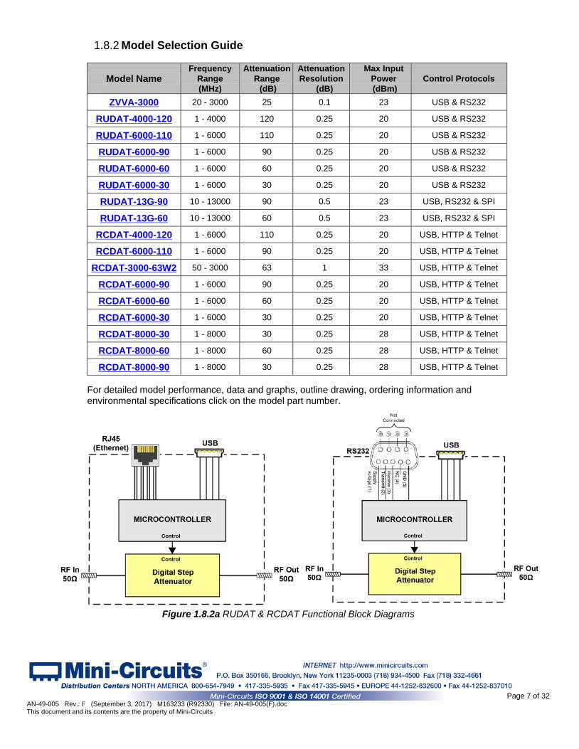
1.8.2 Model Selection Guide
Model Name Frequency
Range (MHz)
Attenuation Range (dB)
Attenuation Resolution
(dB)
Max Input Power (dBm)
Control Protocols
ZVVA-3000 20 - 3000 25 0.1 23 USB & RS232
RUDAT-4000-120 1 - 4000 120 0.25 20 USB & RS232
RUDAT-6000-110 1 - 6000 110 0.25 20 USB & RS232
RUDAT-6000-90 1 - 6000 90 0.25 20 USB & RS232
RUDAT-6000-60 1 - 6000 60 0.25 20 USB & RS232
RUDAT-6000-30 1 - 6000 30 0.25 20 USB & RS232
RUDAT-13G-90 10 - 13000 90 0.5 23 USB, RS232 & SPI
RUDAT-13G-60 10 - 13000 60 0.5 23 USB, RS232 & SPI
RCDAT-4000-120 1 - 6000 110 0.25 20 USB, HTTP & Telnet
RCDAT-6000-110 1 - 6000 90 0.25 20 USB, HTTP & Telnet
RCDAT-3000-63W2 50 - 3000 63 1 33 USB, HTTP & Telnet
RCDAT-6000-90 1 - 6000 90 0.25 20 USB, HTTP & Telnet
RCDAT-6000-60 1 - 6000 60 0.25 20 USB, HTTP & Telnet
RCDAT-6000-30 1 - 6000 30 0.25 20 USB, HTTP & Telnet
RCDAT-8000-30 1 - 8000 30 0.25 28 USB, HTTP & Telnet
RCDAT-8000-60 1 - 8000 60 0.25 28 USB, HTTP & Telnet
RCDAT-8000-90 1 - 8000 30 0.25 28 USB, HTTP & Telnet For detailed model performance, data and graphs, outline drawing, ordering information and environmental specifications click on the model part number.
Figure 1.8.2a RUDAT & RCDAT Functional Block Diagrams
Page 7 of 32 AN-49-005 Rev.: F (September 3, 2017) M163233 (R92330) File: AN-49-005(F).doc This document and its contents are the property of Mini-Circuits
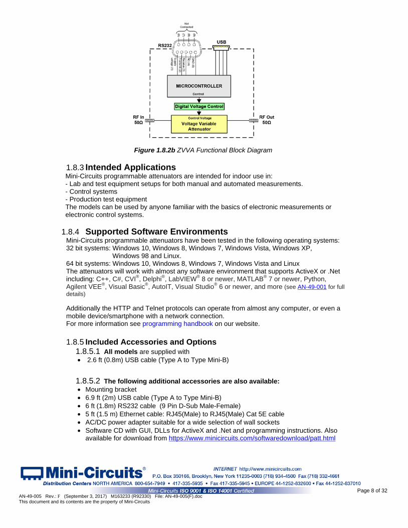
Figure 1.8.2b ZVVA Functional Block Diagram
1.8.3 Intended Applications Mini-Circuits programmable attenuators are intended for indoor use in: - Lab and test equipment setups for both manual and automated measurements. - Control systems - Production test equipment The models can be used by anyone familiar with the basics of electronic measurements or electronic control systems.
1.8.4 Supported Software Environments Mini-Circuits programmable attenuators have been tested in the following operating systems: 32 bit systems: Windows 10, Windows 8, Windows 7, Windows Vista, Windows XP,
Windows 98 and Linux. 64 bit systems: Windows 10, Windows 8, Windows 7, Windows Vista and Linux The attenuators will work with almost any software environment that supports ActiveX or .Net including: C++, C#, CVI®, Delphi®, LabVIEW® 8 or newer, MATLAB® 7 or newer, Python, Agilent VEE®, Visual Basic®, AutoIT, Visual Studio® 6 or newer, and more (see AN-49-001 for full details) Additionally the HTTP and Telnet protocols can operate from almost any computer, or even a mobile device/smartphone with a network connection. For more information see programming handbook on our website. 1.8.5 Included Accessories and Options
1.8.5.1 All models are supplied with • 2.6 ft (0.8m) USB cable (Type A to Type Mini-B)
1.8.5.2 The following additional accessories are also available: • Mounting bracket • 6.9 ft (2m) USB cable (Type A to Type Mini-B) • 6 ft (1.8m) RS232 cable (9 Pin D-Sub Male-Female) • 5 ft (1.5 m) Ethernet cable: RJ45(Male) to RJ45(Male) Cat 5E cable • AC/DC power adapter suitable for a wide selection of wall sockets • Software CD with GUI, DLLs for ActiveX and .Net and programming instructions. Also
available for download from https://www.minicircuits.com/softwaredownload/patt.html
Page 8 of 32 AN-49-005 Rev.: F (September 3, 2017) M163233 (R92330) File: AN-49-005(F).doc This document and its contents are the property of Mini-Circuits
1.8.6 Conformity Mini-Circuits series of programmable attenuators conform to all requirements for the following international standards:
RoHS – The models comply with EU directive for Restriction of Hazardous Substances for 6 substances.
USB 2.0 – The models meet the specifications of the Universal Serial Bus Ver. 2.0 communication standard as described by USB-IF.
USB HID – The models meet the requirements for Universal Serial Bus Human Interface Devices according to USB-IF’s Device Class Definition for Human Interface Devices firmware rev. 1.11
RUDAT series models also comply with: RS232 – The RUDAT series models meet all requirements for RS232 standard.
RCDAT series models also comply with: TCP/IP – The RCDAT series models’ Ethernet communication complies with the
specifications of the Transmission Control Protocol (TCP) and Internet Protocol (IP) as defined in RFC 791 and RFC 793.
HTTP – The RCDAT series models’ support all requirements for communicating with the Hypertext Transfer Protocol (HTTP) as defined in RFC 1945.
Telnet – The RCDAT series models’ support all requirements for communicating with the Telnet protocol, as defined in RFC 854
Page 9 of 32 AN-49-005 Rev.: F (September 3, 2017) M163233 (R92330) File: AN-49-005(F).doc This document and its contents are the property of Mini-Circuits
2 Chapter 2 – Installation and Setup
2.1 Software Setup
System requirements for the programmable attenuator models are a computer (Pentium II or better) with the following support depending on the control method used:
RS232 control SPI USB control Ethernet control Serial COM port 3-wire I/O control
at LVTTL USB HID Network connection
When using the supplied power adaptor a power source of 110-220VAC (with socket matching one of the two pin plugs provided) is also needed. To run the GUI program a Windows operating system for either 32 or 64 bits is required as well.
If you have had any problems installing the software, we’re here to help.
Try following these complete step-by-step instructions. If you still experience problems, give us a call at Mini-Circuits Worldwide Technical support. It’s (718) 934-4500 or e-mail [email protected] for North America or go to minicircuits.com/contact/worldwide_ tech_support.html for other regional numbers and addresses.
2.1.1 First save all work in progress and close any other programs that may be running.
2.1.2 Next, insert the Mini-Circuits CD into the CD-ROM drive, or download the full CD software from minicircuits.com. If installing from files downloaded from the web, unzip the downloaded files to a temporary folder on your local computer, then open the file folder you created, and double-click the “Install” icon. Note: Saving the directory in an excessively long path may result in problems during
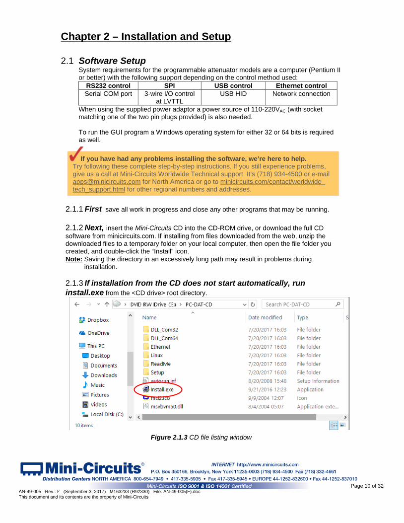
installation. 2.1.3 If installation from the CD does not start automatically, run install.exe from the <CD drive> root directory.
Figure 2.1.3 CD file listing window
Page 10 of 32 AN-49-005 Rev.: F (September 3, 2017) M163233 (R92330) File: AN-49-005(F).doc This document and its contents are the property of Mini-Circuits
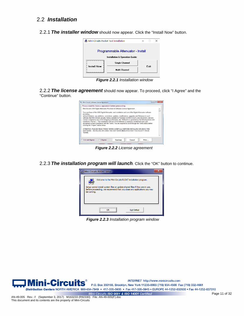
Figure 2.2.1 Installation window
2.2 Installation
2.2.1 The installer window should now appear. Click the “Install Now” button.
2.2.2 The license agreement should now appear. To proceed, click “I Agree” and the “Continue” button.
Figure 2.2.2 License agreement
2.2.3 The installation program will launch. Click the “OK” button to continue.
Figure 2.2.3 Installation program window
Page 11 of 32 AN-49-005 Rev.: F (September 3, 2017) M163233 (R92330) File: AN-49-005(F).doc This document and its contents are the property of Mini-Circuits
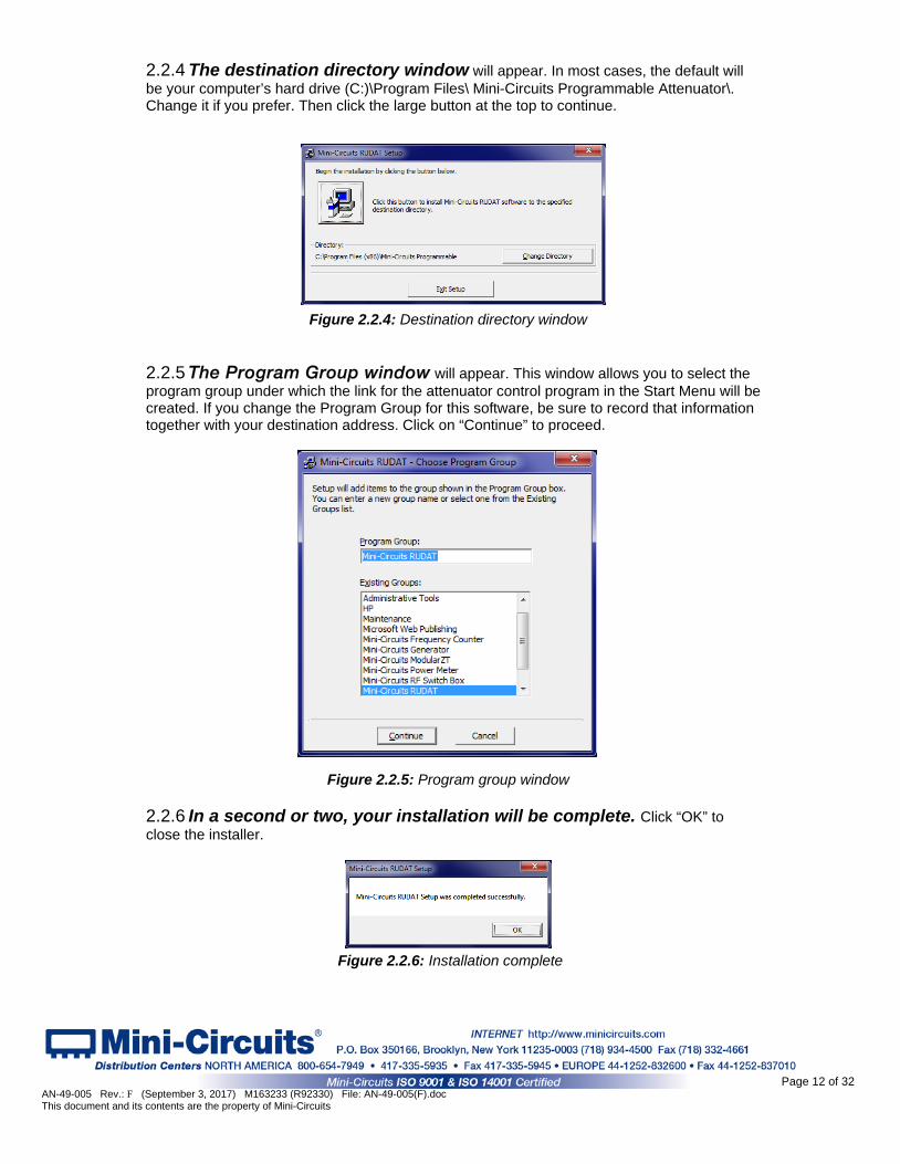
2.2.4 The destination directory window will appear. In most cases, the default will be your computer’s hard drive (C:)\Program Files\ Mini-Circuits Programmable Attenuator\. Change it if you prefer. Then click the large button at the top to continue.
Figure 2.2.4: Destination directory window
2.2.5 The Program Group window will appear. This window allows you to select the program group under which the link for the attenuator control program in the Start Menu will be created. If you change the Program Group for this software, be sure to record that information together with your destination address. Click on “Continue” to proceed.
Figure 2.2.5: Program group window
2.2.6 In a second or two, your installation will be complete. Click “OK” to close the installer.
Figure 2.2.6: Installation complete
Page 12 of 32 AN-49-005 Rev.: F (September 3, 2017) M163233 (R92330) File: AN-49-005(F).doc This document and its contents are the property of Mini-Circuits
2.3 Attenuator Physical Setup
The maximum allowed RF input for programmable attenuators models is reduced at low frequencies. Check the individual model datasheet and do not exceed the specified limits.
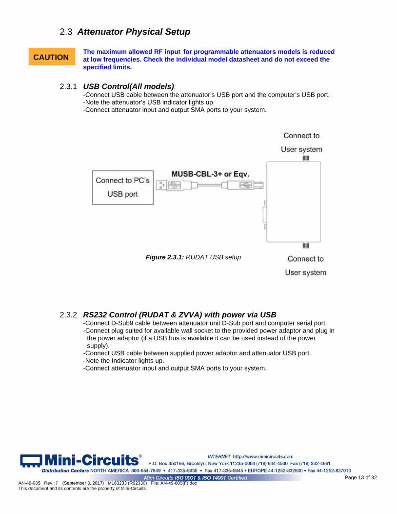
2.3.1 USB Control(All models): -Connect USB cable between the attenuator’s USB port and the computer’s USB port. -Note the attenuator’s USB indicator lights up. -Connect attenuator input and output SMA ports to your system.
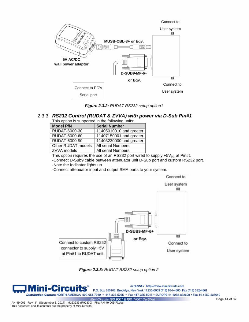
2.3.2 RS232 Control (RUDAT & ZVVA) with power via USB
-Connect D-Sub9 cable between attenuator unit D-Sub port and computer serial port. -Connect plug suited for available wall socket to the provided power adaptor and plug in
the power adaptor (if a USB bus is available it can be used instead of the power supply).
-Connect USB cable between supplied power adaptor and attenuator USB port. -Note the Indicator lights up. -Connect attenuator input and output SMA ports to your system.
Figure 2.3.1: RUDAT USB setup
CAUTION
Page 13 of 32 AN-49-005 Rev.: F (September 3, 2017) M163233 (R92330) File: AN-49-005(F).doc This document and its contents are the property of Mini-Circuits
5V AC/DC wall power adaptor
Connect to PC’s
Serial port
MUSB-CBL-3+ or Eqv.
Connect to
User system
D-SUB9-MF-6+
or Eqv.
Connect to
User system
Figure 2.3.2: RUDAT RS232 setup option1
2.3.3 RS232 Control (RUDAT & ZVVA) with power via D-Sub Pin#1
This option is supported in the following units: Model P/N Serial Number RUDAT-6000-30 11405010010 and greater RUDAT-6000-60 11407150001 and greater RUDAT-6000-90 11403230000 and greater Other RUDAT models All serial Numbers ZVVA models All serial Numbers This option requires the use of an RS232 port wired to supply +5VDC at Pin#1 -Connect D-Sub9 cable between attenuator unit D-Sub port and custom RS232 port. -Note the Indicator lights up. -Connect attenuator input and output SMA ports to your system.
Figure 2.3.3: RUDAT RS232 setup option 2
Page 14 of 32 AN-49-005 Rev.: F (September 3, 2017) M163233 (R92330) File: AN-49-005(F).doc This document and its contents are the property of Mini-Circuits

2.3.4 Ethernet Control (RCDAT)
-Connect plug suited for available wall socket to the provided power adaptor and plug in the power adaptor (if a USB port is available it can be used instead of the AC mains power adapter).
-Connect USB cable between supplied power adaptor and RCDAT USB port. -Note the USB indicator lights up. -Connect a standard network cable between RCDAT unit RJ45 socket and network port. -Note the network indicators on the RJ45 socket of the RCDAT unit light up after a few seconds. -Connect RCDAT input and output SMA ports to your system.
Figure 2.3.4: RCDAT Ethernet setup
2.3.5 SPI Control (RUDAT-13G-xx)
- Connect the SPI Clock, Data and Latch Enable pins (See pinout below) to your I/O control device
-Connect power as for RS232 control -Note the Indicator lights up. -Connect RUDAT input and output SMA ports to your system.
Notes: SPI control allows the device’s attenuation to be set using a simple serial data sequence of LVTTL logic levels, without the need for a PC and minimal control hardware or software. The SPI voltage levels and timing instructions are covered in the model’s datasheet. This is a synchronous communication method designed for minimal control systems and thus, it is not possible to query any of the attenuator’s parameters in this mode of operation
Parameter Conditions Min. Typ. Max. Units
Voltage levels Logic High Voltage Input 2.1 ̶ 3.3 V Logic Low Voltage Input 0 ̶ 0.8 Control Current Per Pin ̶ ̶ 1 mA
Clock Frequency ̶ ̶ ̶ 10 MHz
Page 15 of 32 AN-49-005 Rev.: F (September 3, 2017) M163233 (R92330) File: AN-49-005(F).doc This document and its contents are the property of Mini-Circuits
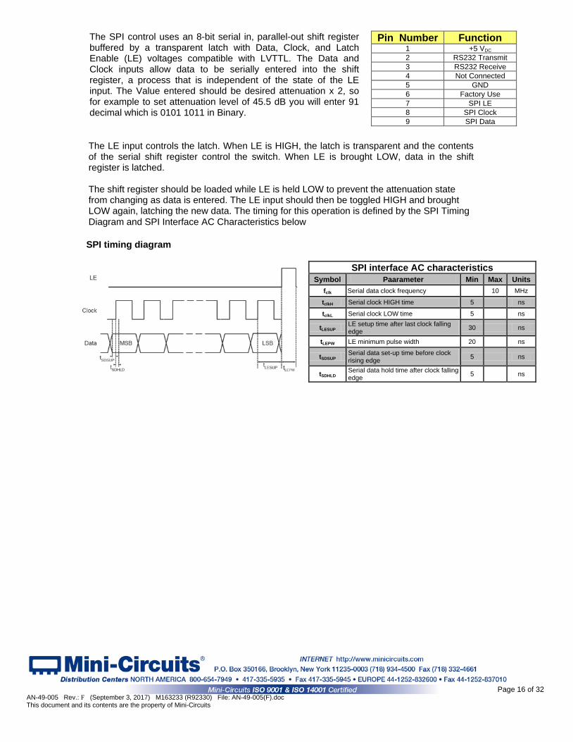
SPI timing diagram
SPI interface AC characteristics Symbol Paarameter Min Max Units
fclk Serial data clock frequency 10 MHz
tclkH Serial clock HIGH time 5 ns
tclkL Serial clock LOW time 5 ns
tLESUP LE setup time after last clock falling edge 30 ns
tLEPW LE minimum pulse width 20 ns
tSDSUP Serial data set-up time before clock rising edge 5 ns
tSDHLD Serial data hold time after clock falling edge 5 ns
The SPI control uses an 8-bit serial in, parallel-out shift register buffered by a transparent latch with Data, Clock, and Latch Enable (LE) voltages compatible with LVTTL. The Data and Clock inputs allow data to be serially entered into the shift register, a process that is independent of the state of the LE input. The Value entered should be desired attenuation x 2, so for example to set attenuation level of 45.5 dB you will enter 91 decimal which is 0101 1011 in Binary.
The LE input controls the latch. When LE is HIGH, the latch is transparent and the contents of the serial shift register control the switch. When LE is brought LOW, data in the shift register is latched. The shift register should be loaded while LE is held LOW to prevent the attenuation state from changing as data is entered. The LE input should then be toggled HIGH and brought LOW again, latching the new data. The timing for this operation is defined by the SPI Timing Diagram and SPI Interface AC Characteristics below
Pin Number Function 1 +5 VDC 2 RS232 Transmit 3 RS232 Receive 4 Not Connected 5 GND 6 Factory Use 7 SPI LE 8 SPI Clock 9 SPI Data
Page 16 of 32 AN-49-005 Rev.: F (September 3, 2017) M163233 (R92330) File: AN-49-005(F).doc This document and its contents are the property of Mini-Circuits
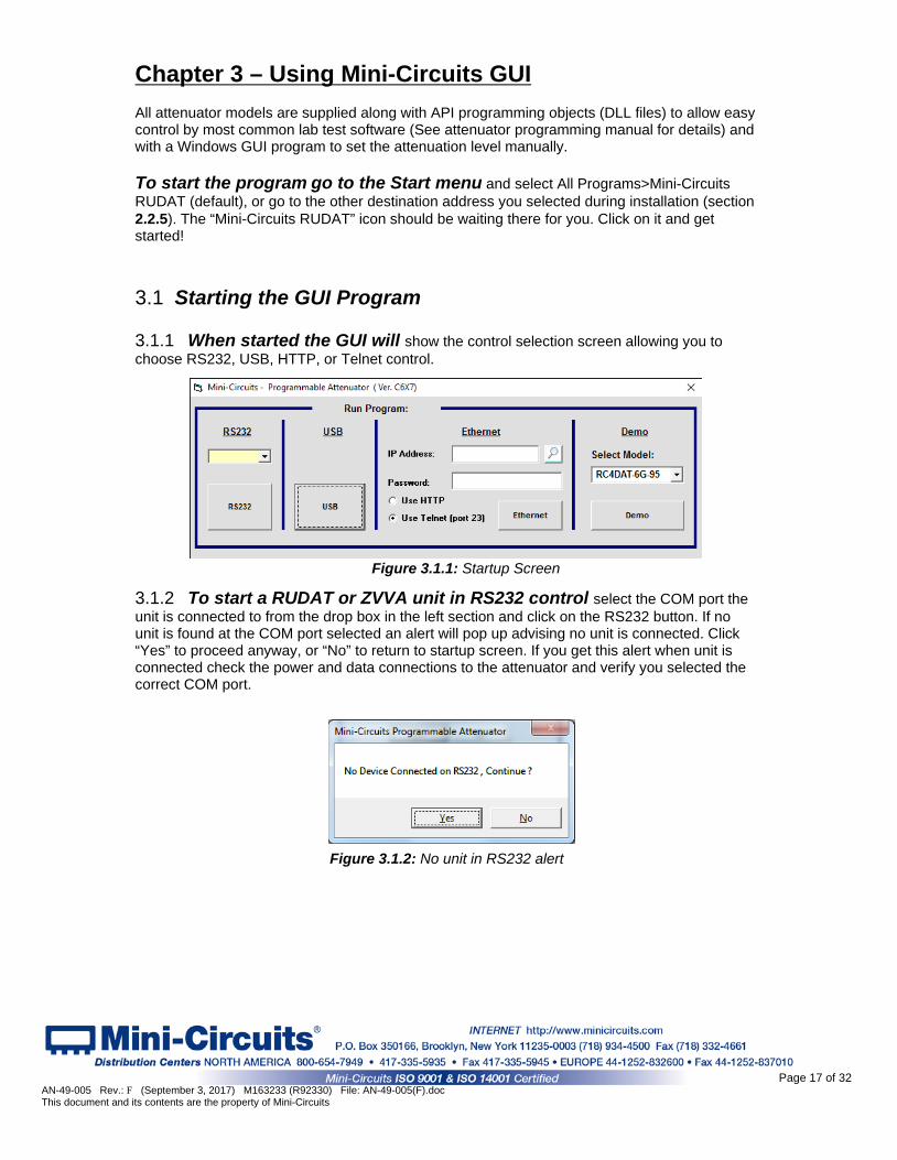
3 Chapter 3 – Using Mini-Circuits GUI All attenuator models are supplied along with API programming objects (DLL files) to allow easy control by most common lab test software (See attenuator programming manual for details) and with a Windows GUI program to set the attenuation level manually. To start the program go to the Start menu and select All Programs>Mini-Circuits RUDAT (default), or go to the other destination address you selected during installation (section 2.2.5). The “Mini-Circuits RUDAT” icon should be waiting there for you. Click on it and get started! 3.1 Starting the GUI Program
3.1.1 When started the GUI will show the control selection screen allowing you to choose RS232, USB, HTTP, or Telnet control. 3.1.2 To start a RUDAT or ZVVA unit in RS232 control select the COM port the unit is connected to from the drop box in the left section and click on the RS232 button. If no unit is found at the COM port selected an alert will pop up advising no unit is connected. Click “Yes” to proceed anyway, or “No” to return to startup screen. If you get this alert when unit is connected check the power and data connections to the attenuator and verify you selected the correct COM port.
Figure 3.1.2: No unit in RS232 alert
Figure 3.1.1: Startup Screen
Page 17 of 32 AN-49-005 Rev.: F (September 3, 2017) M163233 (R92330) File: AN-49-005(F).doc This document and its contents are the property of Mini-Circuits
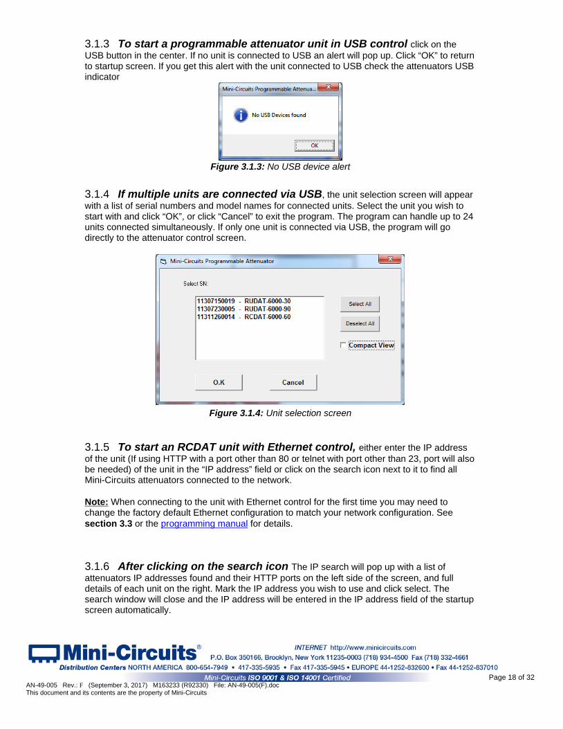
3.1.3 To start a programmable attenuator unit in USB control click on the USB button in the center. If no unit is connected to USB an alert will pop up. Click “OK” to return to startup screen. If you get this alert with the unit connected to USB check the attenuators USB indicator
Figure 3.1.3: No USB device alert 3.1.4 If multiple units are connected via USB, the unit selection screen will appear with a list of serial numbers and model names for connected units. Select the unit you wish to start with and click “OK”, or click “Cancel” to exit the program. The program can handle up to 24 units connected simultaneously. If only one unit is connected via USB, the program will go directly to the attenuator control screen.
Figure 3.1.4: Unit selection screen 3.1.5 To start an RCDAT unit with Ethernet control, either enter the IP address of the unit (If using HTTP with a port other than 80 or telnet with port other than 23, port will also be needed) of the unit in the “IP address” field or click on the search icon next to it to find all Mini-Circuits attenuators connected to the network. Note: When connecting to the unit with Ethernet control for the first time you may need to change the factory default Ethernet configuration to match your network configuration. See section 3.3 or the programming manual for details. 3.1.6 After clicking on the search icon The IP search will pop up with a list of attenuators IP addresses found and their HTTP ports on the left side of the screen, and full details of each unit on the right. Mark the IP address you wish to use and click select. The search window will close and the IP address will be entered in the IP address field of the startup screen automatically.
Page 18 of 32 AN-49-005 Rev.: F (September 3, 2017) M163233 (R92330) File: AN-49-005(F).doc This document and its contents are the property of Mini-Circuits
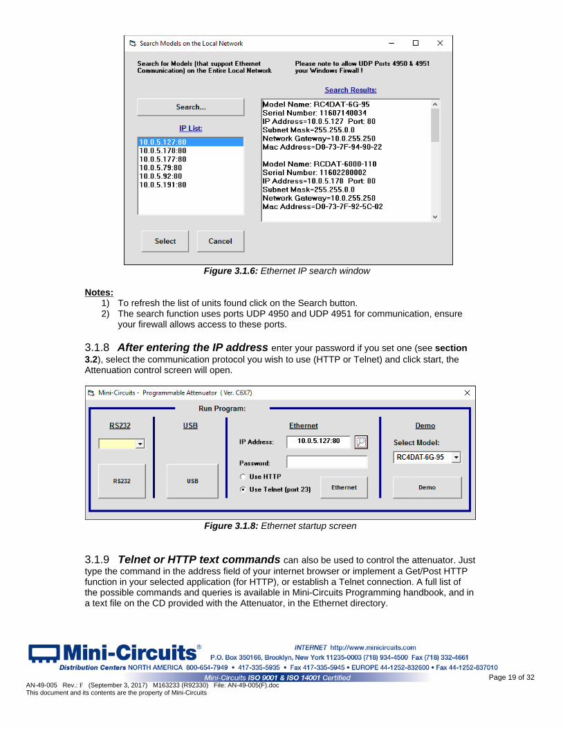
Figure 3.1.6: Ethernet IP search window
Notes:
1) To refresh the list of units found click on the Search button. 2) The search function uses ports UDP 4950 and UDP 4951 for communication, ensure
your firewall allows access to these ports. 3.1.8 After entering the IP address enter your password if you set one (see section 3.2), select the communication protocol you wish to use (HTTP or Telnet) and click start, the Attenuation control screen will open.
Figure 3.1.8: Ethernet startup screen
3.1.9 Telnet or HTTP text commands can also be used to control the attenuator. Just type the command in the address field of your internet browser or implement a Get/Post HTTP function in your selected application (for HTTP), or establish a Telnet connection. A full list of the possible commands and queries is available in Mini-Circuits Programming handbook, and in a text file on the CD provided with the Attenuator, in the Ethernet directory.
Page 19 of 32 AN-49-005 Rev.: F (September 3, 2017) M163233 (R92330) File: AN-49-005(F).doc This document and its contents are the property of Mini-Circuits
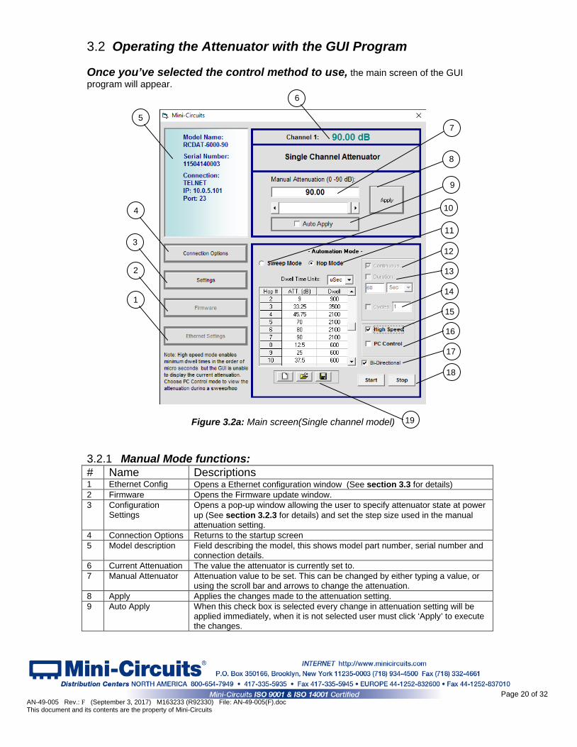
3.2 Operating the Attenuator with the GUI Program Once you’ve selected the control method to use, the main screen of the GUI program will appear. 3.2.1 Manual Mode functions: # Name Descriptions 1 Ethernet Config Opens a Ethernet configuration window (See section 3.3 for details) 2 Firmware Opens the Firmware update window. 3 Configuration
Settings Opens a pop-up window allowing the user to specify attenuator state at power up (See section 3.2.3 for details) and set the step size used in the manual attenuation setting.
4 Connection Options Returns to the startup screen 5 Model description Field describing the model, this shows model part number, serial number and
connection details. 6 Current Attenuation The value the attenuator is currently set to. 7 Manual Attenuator Attenuation value to be set. This can be changed by either typing a value, or
using the scroll bar and arrows to change the attenuation. 8 Apply Applies the changes made to the attenuation setting. 9 Auto Apply When this check box is selected every change in attenuation setting will be
applied immediately, when it is not selected user must click ‘Apply’ to execute the changes.
Figure 3.2a: Main screen(Single channel model)
4
7
8
3
2
1
5
6
9
10
11
12
13
14
15
16
17
18
19
Page 20 of 32 AN-49-005 Rev.: F (September 3, 2017) M163233 (R92330) File: AN-49-005(F).doc This document and its contents are the property of Mini-Circuits
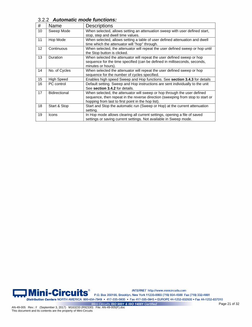
3.2.2 Automatic mode functions: # Name Descriptions 10 Sweep Mode When selected, allows setting an attenuation sweep with user defined start,
stop, step and dwell time values. 11 Hop Mode When selected, allows setting a table of user defined attenuation and dwell
time which the attenuator will "hop" through. 12 Continuous When selected, the attenuator will repeat the user defined sweep or hop until
the Stop button is clicked. 13 Duration When selected the attenuator will repeat the user defined sweep or hop
sequence for the time specified (can be defined in milliseconds, seconds, minutes or hours).
14 No. of Cycles When selected the attenuator will repeat the user defined sweep or hop sequence for the number of cycles specified.
15 High Speed Enables high speed Sweep and Hop functions. See section 3.4.3 for details 16 PC control Default setting. Sweep and Hop instructions are sent individually to the unit
See section 3.4.2 for details. 17 Bidirectional When selected, the attenuator will sweep or hop through the user defined
sequence, then repeat in the reverse direction (sweeping from stop to start or hopping from last to first point in the hop list).
18 Start & Stop Start and Stop the automatic run (Sweep or Hop) at the current attenuation setting.
19 Icons In Hop mode allows clearing all current settings, opening a file of saved settings or saving current settings. Not available in Sweep mode.
Page 21 of 32 AN-49-005 Rev.: F (September 3, 2017) M163233 (R92330) File: AN-49-005(F).doc This document and its contents are the property of Mini-Circuits
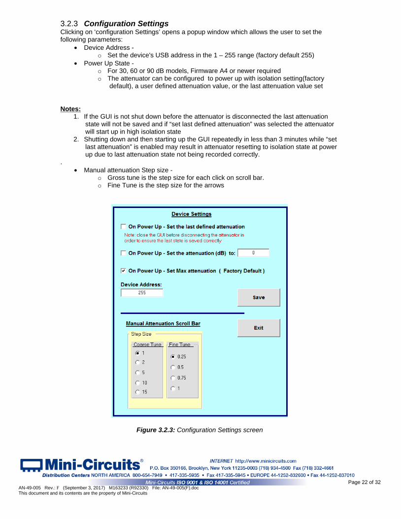
3.2.3 Configuration Settings Clicking on ‘configuration Settings’ opens a popup window which allows the user to set the following parameters:
• Device Address - o Set the device's USB address in the 1 – 255 range (factory default 255)
• Power Up State - o For 30, 60 or 90 dB models, Firmware A4 or newer required o The attenuator can be configured to power up with isolation setting(factory
default), a user defined attenuation value, or the last attenuation value set
Notes: 1. If the GUI is not shut down before the attenuator is disconnected the last attenuation
state will not be saved and if “set last defined attenuation” was selected the attenuator will start up in high isolation state
2. Shutting down and then starting up the GUI repeatedly in less than 3 minutes while “set last attenuation” is enabled may result in attenuator resetting to isolation state at power up due to last attenuation state not being recorded correctly.
. • Manual attenuation Step size -
o Gross tune is the step size for each click on scroll bar. o Fine Tune is the step size for the arrows
Figure 3.2.3: Configuration Settings screen
Page 22 of 32 AN-49-005 Rev.: F (September 3, 2017) M163233 (R92330) File: AN-49-005(F).doc This document and its contents are the property of Mini-Circuits
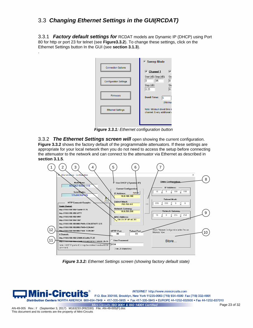
3.3 Changing Ethernet Settings in the GUI(RCDAT) 3.3.1 Factory default settings for RCDAT models are Dynamic IP (DHCP) using Port 80 for http or port 23 for telnet (see Figure 3.3.2). To change these settings, click on the Ethernet Settings button In the GUI (see section 3.1.3). .
Figure 3.3.1: USB Control
3.3.2 The Ethernet Settings screen will open showing the current configuration. Figure 3.3.2 shows the factory default of the programmable attenuators. If these settings are appropriate for your local network then you do not need to access the setup before connecting the attenuator to the network and can connect to the attenuator via Ethernet as described in section 3.1.5.
Figure 3.3.2: Ethernet Settings screen (showing factory default state)
9
4 2 6
11
1 3 7
10 12
5
8
Figure 3.3.1: Ethernet configuration button
Page 23 of 32 AN-49-005 Rev.: F (September 3, 2017) M163233 (R92330) File: AN-49-005(F).doc This document and its contents are the property of Mini-Circuits
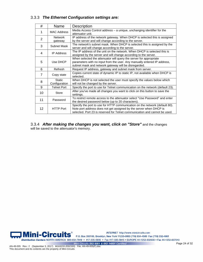
3.3.3 The Ethernet Configuration settings are:
# Name Description
1 MAC Address Media Access Control address – a unique, unchanging identifier for the attenuator unit.
2 Network gateway
IP address of the network gateway. When DHCP is selected this is assigned by the server and will change according to the server.
3 Subnet Mask The network's subnet mask. When DHCP is selected this is assigned by the server and will change according to the server.
4 IP Address The IP address of the unit on the network. When DHCP is selected this is assigned by the server and will change according to the server.
5 Use DHCP When selected the attenuator will query the server for appropriate parameters with no input from the user. Any manually entered IP address, subnet mask and network gateway will be disregarded.
6 Refresh Request IP address, gateway and subnet mask from server.
7 Copy state Copies current state of dynamic IP to static IP, not available when DHCP is selected.
8 Static Configuration
When DHCP is not selected the user must specify the values below which will not be changed by the server.
9 Telnet Port Specify the port to use for Telnet communication on the network (default 23).
10 Store After you've made all changes you want to click on this button to save the settings.
11 Password To restrict remote access to the attenuator select "Use Password" and enter the desired password below (up to 20 characters).
12 HTTP Port Specify the port to use for HTTP communication on the network (default 80). Note port address does not get assigned by the server when DHCP is selected. Port 23 is reserved for Telnet communication and cannot be used.
3.3.4 After making the changes you want, click on "Store" and the changes will be saved to the attenuator's memory.
Page 24 of 32 AN-49-005 Rev.: F (September 3, 2017) M163233 (R92330) File: AN-49-005(F).doc This document and its contents are the property of Mini-Circuits
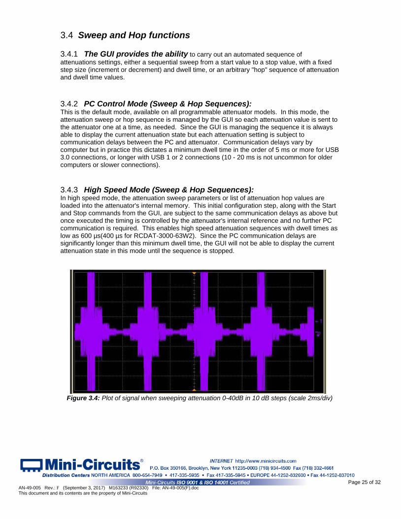
3.4 Sweep and Hop functions 3.4.1 The GUI provides the ability to carry out an automated sequence of attenuations settings, either a sequential sweep from a start value to a stop value, with a fixed step size (increment or decrement) and dwell time, or an arbitrary "hop" sequence of attenuation and dwell time values. 3.4.2 PC Control Mode (Sweep & Hop Sequences): This is the default mode, available on all programmable attenuator models. In this mode, the attenuation sweep or hop sequence is managed by the GUI so each attenuation value is sent to the attenuator one at a time, as needed. Since the GUI is managing the sequence it is always able to display the current attenuation state but each attenuation setting is subject to communication delays between the PC and attenuator. Communication delays vary by computer but in practice this dictates a minimum dwell time in the order of 5 ms or more for USB 3.0 connections, or longer with USB 1 or 2 connections (10 - 20 ms is not uncommon for older computers or slower connections). 3.4.3 High Speed Mode (Sweep & Hop Sequences): In high speed mode, the attenuation sweep parameters or list of attenuation hop values are loaded into the attenuator's internal memory. This initial configuration step, along with the Start and Stop commands from the GUI, are subject to the same communication delays as above but once executed the timing is controlled by the attenuator's internal reference and no further PC communication is required. This enables high speed attenuation sequences with dwell times as low as 600 µs(400 µs for RCDAT-3000-63W2). Since the PC communication delays are significantly longer than this minimum dwell time, the GUI will not be able to display the current attenuation state in this mode until the sequence is stopped.
Figure 3.4: Plot of signal when sweeping attenuation 0-40dB in 10 dB steps (scale 2ms/div)
Page 25 of 32 AN-49-005 Rev.: F (September 3, 2017) M163233 (R92330) File: AN-49-005(F).doc This document and its contents are the property of Mini-Circuits
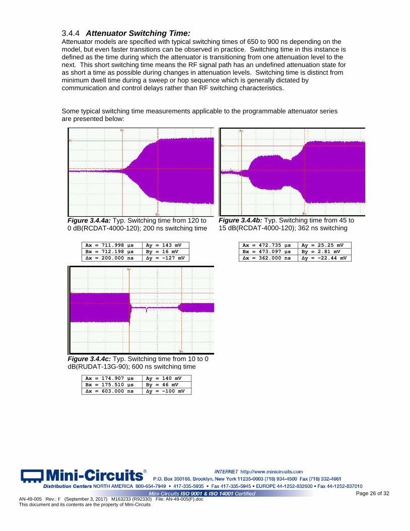
3.4.4 Attenuator Switching Time: Attenuator models are specified with typical switching times of 650 to 900 ns depending on the model, but even faster transitions can be observed in practice. Switching time in this instance is defined as the time during which the attenuator is transitioning from one attenuation level to the next. This short switching time means the RF signal path has an undefined attenuation state for as short a time as possible during changes in attenuation levels. Switching time is distinct from minimum dwell time during a sweep or hop sequence which is generally dictated by communication and control delays rather than RF switching characteristics. Some typical switching time measurements applicable to the programmable attenuator series are presented below:
Ax = 711.998 µs Ay = 143 mV Ax = 472.735 µs Ay = 25.25 mV Bx = 712.198 µs By = 16 mV Bx = 473.097 µs By = 2.81 mV Δx = 200.000 ns Δy = -127 mV Δx = 362.000 ns Δy = -22.44 mV
Ax = 174.907 µs Ay = 140 mV Bx = 175.510 µs By = 46 mV Δx = 603.000 ns Δy = -100 mV
Figure 3.4.4a: Typ. Switching time from 120 to 0 dB(RCDAT-4000-120); 200 ns switching time
Figure 3.4.4b: Typ. Switching time from 45 to 15 dB(RCDAT-4000-120); 362 ns switching
Figure 3.4.4c: Typ. Switching time from 10 to 0 dB(RUDAT-13G-90); 600 ns switching time
Page 26 of 32 AN-49-005 Rev.: F (September 3, 2017) M163233 (R92330) File: AN-49-005(F).doc This document and its contents are the property of Mini-Circuits
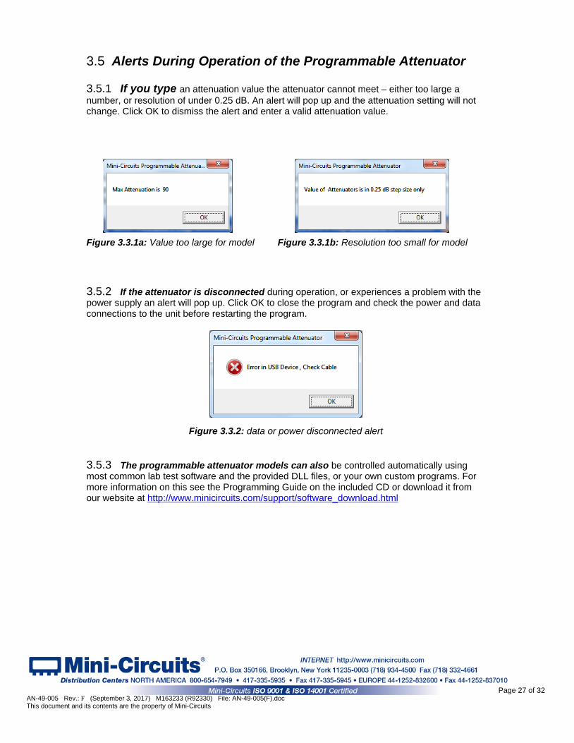
3.5 Alerts During Operation of the Programmable Attenuator 3.5.1 If you type an attenuation value the attenuator cannot meet – either too large a number, or resolution of under 0.25 dB. An alert will pop up and the attenuation setting will not change. Click OK to dismiss the alert and enter a valid attenuation value.
Figure 3.3.1a: Value too large for model Figure 3.3.1b: Resolution too small for model 3.5.2 If the attenuator is disconnected during operation, or experiences a problem with the power supply an alert will pop up. Click OK to close the program and check the power and data connections to the unit before restarting the program.
Figure 3.3.2: data or power disconnected alert
3.5.3 The programmable attenuator models can also be controlled automatically using most common lab test software and the provided DLL files, or your own custom programs. For more information on this see the Programming Guide on the included CD or download it from our website at http://www.minicircuits.com/support/software_download.html
Page 27 of 32 AN-49-005 Rev.: F (September 3, 2017) M163233 (R92330) File: AN-49-005(F).doc This document and its contents are the property of Mini-Circuits
3.6 Firmware Update
The firmware upgrade process requires a computer running a Windows operating system and with the latest Mini-Circuits GUI (Graphical User Interface) program installed for the model to be upgraded.
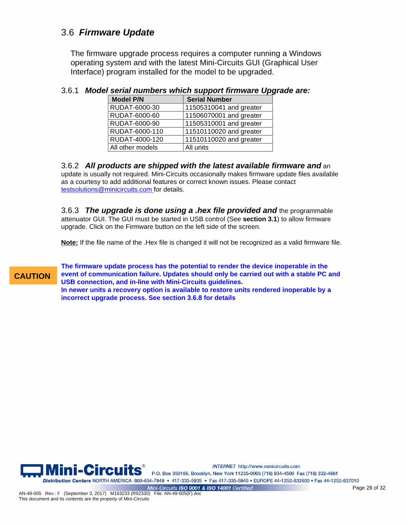
3.6.1 Model serial numbers which support firmware Upgrade are: Model P/N Serial Number RUDAT-6000-30 11505310041 and greater RUDAT-6000-60 11506070001 and greater RUDAT-6000-90 11505310001 and greater RUDAT-6000-110 11510110020 and greater RUDAT-4000-120 11510110020 and greater All other models All units
3.6.2 All products are shipped with the latest available firmware and an update is usually not required. Mini-Circuits occasionally makes firmware update files available as a courtesy to add additional features or correct known issues. Please contact [email protected] for details.
3.6.3 The upgrade is done using a .hex file provided and the programmable attenuator GUI. The GUI must be started in USB control (See section 3.1) to allow firmware upgrade. Click on the Firmware button on the left side of the screen. Note: If the file name of the .Hex file is changed it will not be recognized as a valid firmware file. The firmware update process has the potential to render the device inoperable in the event of communication failure. Updates should only be carried out with a stable PC and USB connection, and in-line with Mini-Circuits guidelines. In newer units a recovery option is available to restore units rendered inoperable by a incorrect upgrade process. See section 3.6.8 for details
CAUTION
Page 28 of 32 AN-49-005 Rev.: F (September 3, 2017) M163233 (R92330) File: AN-49-005(F).doc This document and its contents are the property of Mini-Circuits
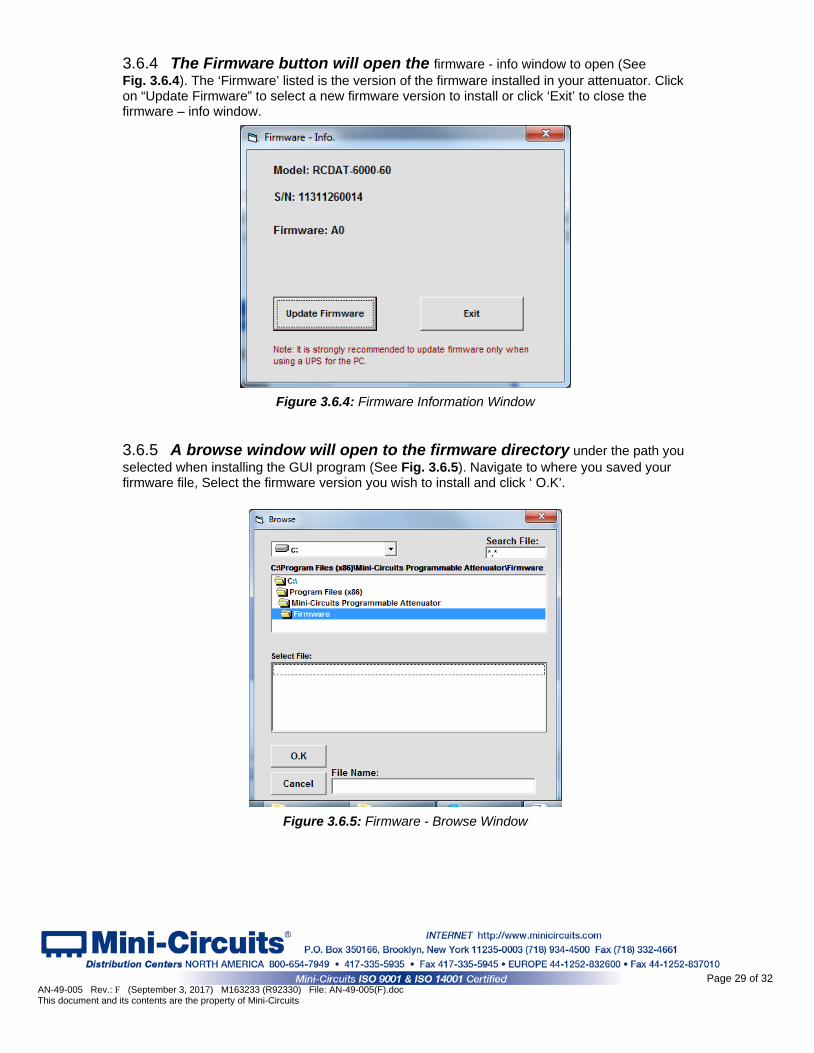
3.6.4 The Firmware button will open the firmware - info window to open (See Fig. 3.6.4). The ‘Firmware’ listed is the version of the firmware installed in your attenuator. Click on “Update Firmware” to select a new firmware version to install or click ‘Exit’ to close the firmware – info window.
Figure 3.6.4: Firmware Information Window
3.6.5 A browse window will open to the firmware directory under the path you selected when installing the GUI program (See Fig. 3.6.5). Navigate to where you saved your firmware file, Select the firmware version you wish to install and click ‘ O.K’.
Figure 3.6.5: Firmware - Browse Window
Page 29 of 32 AN-49-005 Rev.: F (September 3, 2017) M163233 (R92330) File: AN-49-005(F).doc This document and its contents are the property of Mini-Circuits
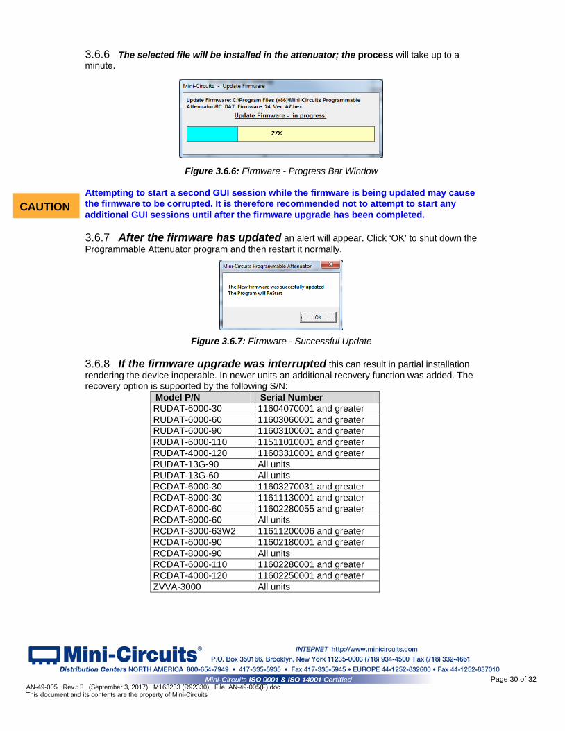
3.6.6 The selected file will be installed in the attenuator; the process will take up to a minute.
Figure 3.6.6: Firmware - Progress Bar Window
Attempting to start a second GUI session while the firmware is being updated may cause the firmware to be corrupted. It is therefore recommended not to attempt to start any additional GUI sessions until after the firmware upgrade has been completed.
3.6.7 After the firmware has updated an alert will appear. Click ‘OK’ to shut down the Programmable Attenuator program and then restart it normally.
Figure 3.6.7: Firmware - Successful Update 3.6.8 If the firmware upgrade was interrupted this can result in partial installation rendering the device inoperable. In newer units an additional recovery function was added. The recovery option is supported by the following S/N:
Model P/N Serial Number RUDAT-6000-30 11604070001 and greater RUDAT-6000-60 11603060001 and greater RUDAT-6000-90 11603100001 and greater RUDAT-6000-110 11511010001 and greater RUDAT-4000-120 11603310001 and greater RUDAT-13G-90 All units RUDAT-13G-60 All units RCDAT-6000-30 11603270031 and greater RCDAT-8000-30 11611130001 and greater RCDAT-6000-60 11602280055 and greater RCDAT-8000-60 All units RCDAT-3000-63W2 11611200006 and greater RCDAT-6000-90 11602180001 and greater RCDAT-8000-90 All units RCDAT-6000-110 11602280001 and greater RCDAT-4000-120 11602250001 and greater ZVVA-3000 All units
CAUTION
Page 30 of 32 AN-49-005 Rev.: F (September 3, 2017) M163233 (R92330) File: AN-49-005(F).doc This document and its contents are the property of Mini-Circuits
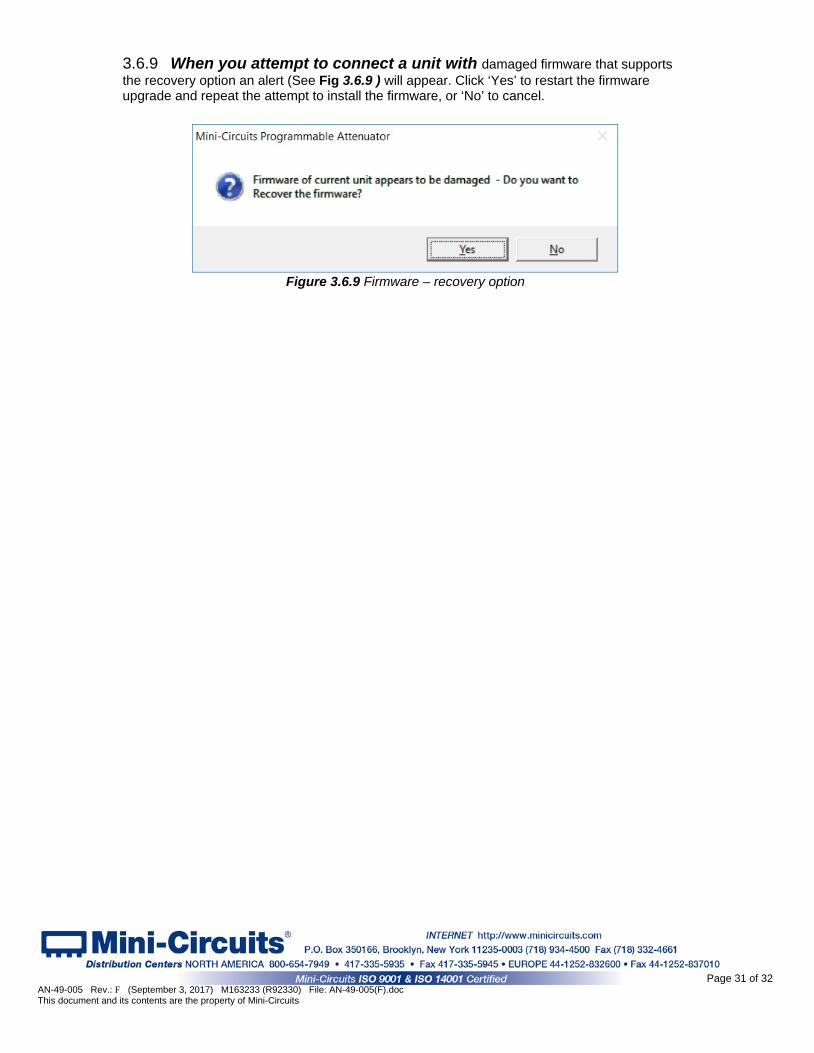
3.6.9 When you attempt to connect a unit with damaged firmware that supports the recovery option an alert (See Fig 3.6.9 ) will appear. Click ‘Yes’ to restart the firmware upgrade and repeat the attempt to install the firmware, or ‘No’ to cancel.
Figure 3.6.9 Firmware – recovery option
Page 31 of 32 AN-49-005 Rev.: F (September 3, 2017) M163233 (R92330) File: AN-49-005(F).doc This document and its contents are the property of Mini-Circuits

4 Chapter 4 – Revision History
March 12, 2015: Created user guide Rev OR. June 26, 2015: Updated user guide per CD Rev. C2 and Firmware Rev. B1, adding high speed
Sweep & Hop, showed firmware upgrade support for RUDAT models. Rev A. August 10, 2015: Rewrote Sweep & Hop section to add more detail to high speed mode and added
section on attenuation switching time with plots showing examples. Rev B. September 16, 2015: Added caution note concerning multiple GUI sessions during firmware
upgrade. October 16, 2015: Added models RCDAT-8000-30 and RCDAT-3000-63W2. August 07, 2016: Added RC4DAT models and RUDAT-132G-90, Added SPI control, Added multi-
channel attenuators to sweep & hop, added third timing diagram, rewrote firmware upgrade to provide contact information for firmware upgrades.
May 08, 2017: Added RUDAT-13G-60 model and Firmware recovery option, moved RC4DAT models to separate user guide.
Aug 06, 2017: Added ZVVA-3000 model, expanded SPI control section .
Page 32 of 32 AN-49-005 Rev.: F (September 3, 2017) M163233 (R92330) File: AN-49-005(F).doc This document and its contents are the property of Mini-Circuits


