UNITED STATES MARINE CORPS MARINE CORPS DETACHMENT
686 MINNESOTA AVE.
FORT LEONARD WOOD, MISSOURI 65473-5850
LESSON PLAN
MAINTENANCE MANAGEMENT
NCOM-A02
NCO MECHANICS COURSE
A16ACU1
REVISED 02/18/2014
APPROVED BY: ________________________ DATE: ________________

(ON SLIDE #1)
INTRODUCTION (10 MIN)
1. GAIN ATTENTION. Show YouTube video of “Angry at computer”.
Guy in office cubical gets angry at his computer and smashes it.
Then explain this is how you feel throughout the work day when
you’re trying to manage your maintenance shop deaing with GCSS-
MC.
________________________________________________________________
________________________________________________________________
________________________________________________________________
(ON SLIDE #2)
2. OVERVIEW. Good morning/afternoon class, my name is
_________. The purpose for this period of instruction is to
provide you with knowledge and skills required to properly
manage your maintenance section utilizing the appropriate
recourses available. To do this we’ll cover the maintenance
production, purpose and capabilities of GCSS-MC, Limited
Technical Inspections, Service Requests, Parts Requisition,
MOD’s, Demand-supported Items /Layettes, Calibrations, and
maintenance related reports.
INSTRUCTOR NOTE
Introduce the learning objectives to the class. Instruct the
students to read the TLO’S and ELO’s located in their student
outline. Ensure that the students understand the TLO’S, the
ELO’S, and what is expected of them.
(ON SLIDE #3)
3. LEARNING OBJECTIVES.
a. TERMINAL LEARNING OBJECTIVES.
(1) Provided engineer equipment, appropriate
records/forms, and references, complete engineer equipment
records and forms, to support mission requirements. (1341-ADMN-
2003)
(2) Given a requirement, data, and the references,
review service request and parts requirement, per the
references. (1341-ADMN-2004)
(3) Provided an item of engineer equipment and the
references, complete commodity manager's modification control
record, to record equipment modifications. (1341-ADMN-2005)
(4) Given a requirement and the references, maintain
Pre-Expended Bins (PEB), to ensure bins are stocked and
maintained for timely maintenance. (1341-ADMN-2007)
(5) Provide a service request, parts requirement, repair
parts, and the references, maintain layettes, to ensure repair
parts are kept in the appropriate layettes bin. (1341-ADMN-2008)
b. ENABLING LEARNING OBJECTIVES.
(1) Without the aid of references, complete the NAVMC
10560 (LTI) per the TM-4700-15/1_ (1341-ADMN-2003a)
(2) With the aid of references, create a service request
per the GPN 3-12 and GPN 1-13. (1341-ADMN-2004a)
(3) With the aid of references, close a service request
per the GPN 3-12 and GPN 1-13. (1341-ADMN-2004b)
(4) Without the aid of reference, identify the purpose of
a Parts Request per the GPN 1-11, GPN 3-11, GPN 2-12, GPN 10-12,
GPN 1-13, GPN 3-13 and MCO P4790.2_. (1341-ADMN-2008a)
(5) Without the aid of references, complete the SF 368
(PQDR) per the TM-4700-15/1_ (1341-ADMN-2003b)
(6) Provided a computer, Internet access, T/E and
references, Validate Modification program per the GPN 4-12 and
MCO P4790.2_. (1341-ADMN-2005a)
(7) Without the aid of reference, identify the
requirements for the Demand-Supported items authorization letter
per the MCO P4400.150_. 1341-ADMN-2007a
(8) Without the aid of reference, identify procedures for
inventory of Demand-Supported Items per the MCO 4400.150_, GPN
1-11, GPN 3-12 and MCO P4790.2_. 1341-ADMN-2007b
(9) Without the aid of references, identify Sub-inventory
Locator procedures per the MCO P4790.2_, GPN 1-11, GPN 3-11, GPN
2-12, GPN 10-12, GPN 1-13, GPN 3-13 and TM 4400-150_. (1341-
ADMN-2008b)
4. METHOD/MEDIA. I’ll be teaching this period of instruction
utilizing the informal lecture, demonstration, practical
application methods; I’ll be aided by the powerpoint
presentation, GCSS UPK player, student handouts, and practical
application materials.
INSTRUCTOR NOTE
Explain Instructional Rating Forms to students.
5. EVALUATION. You’ll be evaluated over this period of
instruction with a written exam, followed by a performance exam
in accordance with your training schedule.
6. SAFETY/CEASE TRAINING (CT) BRIEF. There are no safety
concerns for the classroom portion, however when we transition
to the Maintenance building for the performance exam, we’ll obey
all posted speed limits and use defensive driving techniques in
order to arrive safely at our destination.
(ON SLIDE #4)
TRANSISTION: Are there any questions on what’s going to be
taught, how it’s going to be taught, or how you’re going to be
evaluated? If not let’s talk about Maintenance Production.
________________________________________________________________
________________________________________________________________
________________________________________________________________
BODY (20 HRS)
(ON SLIDE #6)
1. PRODUCTION. (2 HRS)
a. Maintenance Production. is that area of equipment
maintenance, which involves the physical performance of various
maintenance functions. These maintenance functions are
Preventive Maintenance (PM), Corrective Maintenance (CM),
Modification, Calibration, Conversion, Modernization, Overhaul,
and Rebuild.
(ON SLIDE #7)
b. Maintenance Phases.
(ON SLIDE #8)
(1) Acceptance Phase. It is the initial step of the
maintenance process. It consists of Inspection, Scheduling, and
Shop Assignment.
(ON SLIDE #9)
(a) Acceptance Inspection. The purpose of the
acceptance inspection is to verify that the equipment is
complete and prepared for the required maintenance services and
is conducted upon initial receipt by the maintenance section.
The procedures to be followed in the acceptance inspection are
as follows:
1 First, determine that the equipment is complete
and that appropriate operator maintenance, including cleaning,
has been performed. Remove and store collateral equipment and
annotate the LTI/SR unless collateral equipment is required
during the maintenance action. The unit commander should be
informed about equipment which is incomplete or has not been
properly prepared by the unit requesting said maintenance.
2 Next, verify that the SR has been properly
prepared IAW TM-4700-15/1_. This verification includes matching
the data plate’s serial number with the serial number on the SR.
3 After verification of the SR, acceptance of the
equipment for the required services is accomplished by digitally
signing the SR.
4 The last step is to assign the production
priority for use within the maintenance activity. This priority
will be based on the SR priority and other appropriate criteria
established by the maintenance officer or chief.
(ON SLIDE #10-11)
(b) Acceptance Scheduling. The purpose of acceptance
scheduling is to have equipment requiring maintenance arrive at
the maintenance facility at or after the time that the required
maintenance resources are available. This procedure allows the
equipment owner maximum operational use of this equipment while
avoiding needlessly large concentrations of equipment awaiting
maintenance at the maintenance facility. Acceptance scheduling
is normally applicable to all PM’s, modifications, calibrations,
and routine repairs. Scheduling of equipment for maintenance
requires close coordination between the owner and the
maintenance facility if it is to be effective. Procedures for
acceptance scheduling are as follows:
1 First, the owning unit must prepare a deferred
or unit recall SR.
2 Next, the maintenance activity must accept the
SR. Acceptance by the maintenance section includes
establishment, when appropriate, of the date for delivery of the
equipment for the required services.
3 After the SR is accepted, the equipment must be
scheduled, if appropriate, to a specific shop within the
maintenance activity.
(ON SLIDE #12)
(c) Shop Assignment. The assignment of equipment to
a specific maintenance shop within the maintenance activity is
made upon completion of the acceptance inspection and
scheduling, when appropriate. In maintenance sections comprised
of only one maintenance shop, shop assignment occurs at the time
of acceptance of the equipment during the acceptance inspection.
Procedures to be followed in the shop assignments are as
follows:
1 First, identify the type of shop to perform the
required services.
2 Next, review the workloads and available
resources of individual shops within the maintenance activity to
determine which shop should be assigned the SR.
3 Assign the SR to a specific maintenance shop.
When assigning, always consider the priority assigned the SR to
ensure that the equipment readiness of supported units is not
impaired.
4 Assign the Demand-supported Item parts required
for the service to the SR task parts requirement to ensure
availability at the time of induction.
INSTRUCTOR NOTE
Debrief parts from Demand-supported Items to Task.

(ON SLIDE #14)
(2) Equipment Induction Phase.
(a) Induction of the equipment is the physical
commitment of an SR and associated equipment requiring service
to the assigned shop.
(b) Induction of equipment into a specified shop must
be by the priority established in the equipment acceptance
phase. The maintenance shop should request the equipment when
the necessary maintenance resources are available to perform the
required services.
(ON SLIDE #16-17)
(3) Active Maintenance Phase. This phase begins with the
induction of the SR and its associated equipment into the
maintenance shop. This phase is performed in a sequence of
logical steps that are designed to ensure that the required
services are conducted in an efficient and effective manner.
During this phase, continual emphasis is placed on Quality
Control of the actions and tasks performed. The steps to be
followed in the conduct of active maintenance are described in
the following:
(a) Inspection of the equipment. Maintenance personnel
assigned to perform the service will perform a detailed
inspection of the equipment upon induction into the shop. This
inspection serves as a basis for the performance of the
maintenance and includes:
1 Locating, identifying, and inventorying the
equipment and its components.
2 Verify that all equipment records associated
with the required services are prepared IAW GPN 4-12 and
appropriate equipment publications.
(b) Preparation for the performance of maintenance
actions includes the assembly of the appropriate technical
manuals and other technical data, support equipment, and TMDE to
perform required services. Adequate preparation reduces the
actual time required to perform the maintenance and also ensures
that maintenance actions are not initiated for which the
required resources are not available.
(c) Performance of maintenance actions will be per
the appropriate technical manuals. MCO P4790.2_, Appendix “F”
contains the maintenance process and the relationship of
maintenance production to information flow.
(d) PMCS.
1 Obtain required materials for PMCS. If the unit
is not authorized Demand-supported Items, ensure that consumable
supplies required for the PMCS is requested through the task in
sufficient time for scheduled PMCS.
2 Performance of PMCS will be performed per the
procedures established in the applicable technical publication.
Upon completion, update Install Base per the TM-4700-15/1_ and
GPN 4-12.
(e) Corrective Maintenance.
1 Isolate the cause of the equipment malfunction.
2 Obtain required repair parts and secondary
reparables. Demands will be expeditiously submitted when parts
requirements become known.
3 Correct the equipment fault. Fault correction is
the goal of all corrective maintenance actions. Proper
maintenance techniques must be employed to ensure that repair
parts are installed correctly.
(f) Modification control.
1 Obtain required materials IAW appropriate
technical publication, (Modification Instruction).
2 Application of the MI will be IAW the
instructions set forth in the publication. Upon completion of
the modification, update the ERO and appropriate equipment
records per the TM-4700-15/1_.
(g) Calibration. Performance of calibration will be
per the procedures established in MCO 4733.1_ and only at
approved calibration laboratories. Upon completion of
calibrations ensure that the records are updated per the GPN 4-
12.
(h) Checking of completed maintenance tasks on a SR.
Maintenance personnel will check their completed work by
performing the necessary final adjustments on the repaired
equipment. Adjustment procedures in the applicable technical
publication must be followed in detail. Bringing the equipment
performance to within tolerances specified in the technical
publications is a positive indication that the action has been
successfully completed. Adjustments will be performed by, or
under supervision of qualified personnel, using standards and
gauges, which meet or exceed minimum acceptable standards.
(i) Quality control requires a complete equipment
checkout to determine that maintenance actions have been
properly completed and that equipment and shop records are
complete. Qualified supervisory personnel under actual or
simulated operating conditions will conduct equipment checkout.
Equipment that does not perform satisfactorily will be rejected
and recommendations made for further maintenance actions.
Acceptable performance results in the completion of the active
maintenance phase and the movement of the equipment to the
closeout phase.
(j) Time and resources must be allocated to clean up
the maintenance area. Support and TMDE, including tools, must be
cleaned, serviced, and inventoried allowing for future
maintenance actions. TM’s must be returned to the library.
Defective parts and other residue must be removed from the
maintenance area using proper disposal procedures.
(ON SLIDE #19)
(4) Maintenance Closeout Phase.
(a) The closeout phase of the maintenance process
commences when equipment has been repaired and the serviceable
item is to be returned to the owner, or when a decision has been
made to evacuate or dispose of the equipment. Maintenance
personnel will ensure that the closeout process is accurate,
complete, and coordinated.
(b) The closeout phase requires close coordination with
the owning unit personnel to ensure that they are notified as
soon as the equipment is ready for pickup. Any special
packaging, preservation, transportation, and shipping
requirements must be taken care of at this time. The using unit
must make every effort to pick up completed equipment promptly.

(c) In the closeout phase. Maintenance personnel must
ensure that the SR and Install Base have been correctly
completed IAW TM-4700-15/1_and GPN 4-12.
(ON SLIDE #20)
TRANSITION: Now that we know what the Maintenance Phases
consist of, are there any questions? I have a question for you.
Q: What is the acceptance phase? A: It is the initial step of
the maintenance process. It consists of Inspection, Scheduling,
and Shop Assignment. Q2: What is the Equipment Induction Phase?
A2: Induction of the equipment is the physical commitment of an
SR and associated equipment requiring service to the assigned
shop. Q3: What is the Active Maintenance Phase? A3: Induction of
the SR and its associated equipment into the maintenance shop.
________________________________________________________________
________________________________________________________________
________________________________________________________________
(ON SLIDE #21)
BREAK: (10 MIN)
TRANSITION: Did anyone come up with any questions during the
break? If not let’s move onto maintenance functions.
________________________________________________________________
________________________________________________________________
________________________________________________________________
(ON SLIDE #22)
c. Maintenance Function – Preventive Maintenance/Corrective
Maintenance.
(ON SLIDE #23)
(1) PMCS includes the checking and servicing performed by
personnel for maintaining equipment in a satisfactory operating
condition. This is achieved by accomplishing systematic
inspection, detection, and correction of incipient failures
either before they occur or before they develop into major
defects. A systematic PMCS program consists of inspecting,
cleaning, servicing, lubricating, and adjusting; and is the key
to equipment readiness. Effectively administered PMCS will help
prevent early breakdown or failure of equipment, and prevent

costly, complex, and time-consuming repairs and allow the
optimum use of maintenance resources.
(ON SLIDE #25)
(2) The establishment of a PM program and the performance
of timely PM services on equipment are the responsibilities of
the unit owning or using the equipment.
(a) Preventive maintenance will be scheduled per the
commodity chapter (Ch. 3) of the TM-4700-15/1_and GPN 4-12, and
when due the PMCS will be conducted per the applicable equipment
technical publications.
(b) The unit using the equipment is responsible for
PMCS of equipment and maintenance of equipment records for
equipment on Temp. Loan.
(ON SLIDE #26)
(3) PMCS generally is cyclic in nature, one cycle being
completed each year of the equipment’s life. They are frequently
referred to as scheduled maintenance and include PMCS performed
by:
(a) The operator, user, or crew before, during, and
after operation.
(b) The operator or crew on an hourly, daily, monthly,
or special occurrence basis.
(c) Organizational maintenance personnel, assisted by
the operator, on a calendar, mileage, or hours of operation.
(ON SLIDE #27)
(4) The operator or crew will perform a scheduled PMCS
when it is within their authorized EOM. If the equipment must be
evacuated to a maintenance section for scheduled PMCS, the
operator or crew will accompany the equipment, if feasible, and
assist in the performance of the specified PMCS.
(5) Equipment procured with a manufacturer’s warranty will
have PMCS scheduled and performed as indicated in the applicable
TM’s until expiration of the warranty period. Equipment procured
under a warranty is identified by applicable material fielding
plans.
(ON SLIDE #28)
(6) Deferred PMCS. PMCS may be deferred or intervals
extended for the following reasons: equipment is placed in
administrative storage program or equipment is placed on
administrative deadline. The criteria for these types of
programs are as follows:
(ON SLIDE #29)
(a) Not be stored less than 12 months or more than 30
months.
(b) Be in condition code “A”.
(c) Be visually inspected quarterly.
(d) Be exercised every 6 months.
(e) Have a semiannual PMCS before induction.
(f) Have any due PMCS conducted and a new PMCS
scheduled upon removal.
(g) Be in a level “B” (intermediate protection)
preservation per MIL-V-62038. Level “B” packing provides
protection for material under anticipated favorable conditions
of worldwide shipment, handling, and storage.
(h) Only MSC commanders may approve.
INSTRUCTOR NOTE:
Equipment has no defects and 100% SL-3 complete.
(ON SLIDE #30)
(7) Commanding officers may authorize administrative
deadline. When administrative deadline programs are authorized,
the equipment may have batteries and pilferage items removed and
stored and must:
(a) Not be stored less than 6 months or more than 12
months.
(b) Be in a mission capable status.
(c) Be visually inspected monthly.

(d) Have a daily or equivalent PMCS performed in
conjunction with the quarterly exercise.
(e) Have a semiannual or annual PMCS performed within
30 days before induction.
(f) Have any due PMCS conducted and a new PMCS
scheduled upon removal.
(ON SLIDE #31)
(8) Special Preventive Maintenance Checks and Services.
(a) An operating force unit or Marine Corps Reserve
unit alerted for combat or training operation will perform a
limited technical inspection (LTI) of all equipment before
deployment. This LTI is an inspection performed by the unit
maintenance personnel to ensure that the equipment is complete,
safe to operate, and capable of performing its designated
primary combat function.
(b) Upon receipt of all equipment, an appropriate
acceptance LTI and such service required by the equipment’s TM
must be performed. This LTI will include the correction of
defects and the inspection of the equipment to determine if
required modifications have been applied. Upon completion of the
LTI and PMCS, equipment records will be updated.
(c) Special PMCS procedures are necessary if equipment
has been exposed to salt or fresh water, or has been operated in
loose sand or mud. The equipment will be washed thoroughly with
fresh water and appropriate servicing performed as soon as
possible to include checking all areas for contamination.
Servicing will be performed IAW the applicable TM.
(ON SLIDE #32)
(9) Relationship of PMCS to CM. The objective of PMCS is
to reduce CM. This is evident in the following areas:
(a) Common facilities are utilized for both CM and PM.
This requires close scheduling of facilities so that PM services
may be performed while not preventing the timely completion of
CM.

(b) Common servicing. Sometimes a scheduled PMCS is
required during CM; for example, an engine repair could require
oil and filter change. When this occurs, the decision must be
made whether to perform the full PMCS or to appropriately modify
the PMCS. This decision must be made on a case-by-case basis,
dependent upon the extent of tasks common to both PMCS and CM
requirements and the proximity of the next scheduled PMCS.
Ensure SR and Install Base are updated.
(ON SLIDE #33)
(c) Defects discovered during PMCS. Preventive
maintenance actions frequently detect broken or worn parts
before major damage occurs. When this occurs, the decision must
be made whether to perform the necessary CM independently or in
conjunction with the PMCS. Second echelon or higher PMCS will be
completed as far as practical, and the PMCS SR will be closed.
All remaining CM will be accomplished on a separate CM SR.
(ON SLIDE #34)
(d) Evacuation of equipment to a higher echelon for
CM. All PMCS that are due will be performed on equipment before
evacuation of the equipment to a higher echelon of maintenance
for CM. An exception to this policy would be the case where the
PM services would have to be repeated during the CM, such as not
changing the oil when the engine is to be replaced.
1 Equipment waiting or undergoing CM must still
receive its scheduled PMCS.
2 Equipment undergoing repairs at an intermediate
maintenance activity, PMCS’s must be coordinated between the
owner and the IMA.
(ON SLIDE #35)
(10) Corrective Maintenance.
(a) Corrective maintenance consists of all maintenance
actions performed, as a result of failure, to restore equipment
to a specific condition.
(b) The owning unit is responsible for the timely
performance of all CM actions within its authorized EOM. CM
requirements that exceed the EOM authorized by the owning unit

are the responsibility of the designated support maintenance
activity.
(ON SLIDE #36)
(c) Use of Established Corrective Maintenance
Procedures. CM actions will be performed IAW the procedures
established in the appropriate technical manuals. Deviation from
these procedures should be minimized and consistent with the
effective performance of the specific maintenance action.
(ON SLIDE #37)
(11) Maintenance Production Process.
(a) MCO P4790.2_, Appendix “F” contains a series of 12
steps depicting the maintenance production processes. These
steps are presented as guidance and they are intended to show
the logical sequence of steps necessary to complete the various
types of maintenance functions.
(ON SLIDE #39)
(12) Maintenance Cycle Time.
(a) By definition maintenance cycle time is the period
of time equipment is inoperative and requires repairs.
(b) Maximum Maintenance Cycle Time. Relates to the
Intermediate Maintenance Activity (IMA). The maintenance cycle
time commences on the date an item is received into the IMA
(date received in shop (DRIS)). For those items evacuated for
lack of supply support (not mission capable supply (NMCS)) the
IMA will use the second echelon DRIS for determining the maximum
maintenance cycle time. The following maximum maintenance cycle
times are published for equipment inducted in the IMA:
INSTRUCTOR NOTE:
Items evacuated for lack of supply support, can’t order parts
not stocked in supply system.
(ON SLIDE #40)
1 END ITEMS.
a One hundred and eighty days (180) for
West/Mid-Pac units.
b One hundred and twenty days (120) for
continental United States (CONUS) units.
2 SECONDARY REPARABLE (CODE “O”, “F”, “H”, “D”).
a Ninety days (90) for West/Mid-Pac units.
b Sixty days (60) for CONUS units.
(ON SLIDE #41)
(c) Maximum maintenance effort is required to repair
equipment before reaching the maximum maintenance cycle time.
The following are some actions the IMA must take to complete
repairs before the maximum maintenance cycle time is exceeded.
1 Detailed inspection of inducted equipment and
requisition of known faulty components (SecReps/piece parts)
will be accomplished within five (5) working days from the DRIS.
2 All supply sources must be used, to obtain the
required components as authorized by UM 4400-15 or UM 4400-124,
as appropriate. This includes the requisitioning of not-in-stock
parts from other sources including commercial procurement,
fabrication, salvage, and contract maintenance.
3 Repeated supply follow-up actions as outlined in
UM 4400-15 and UM 4400-124 are a must.
(ON SLIDE #42)
(d) When the maximum maintenance cycle time expires or
documentation shows that repairs cannot be completed within the
maximum maintenance cycle time, the following actions will be
followed:
(e) Third echelon shops will report items exceeding
the maximum maintenance cycle time to their supporting fourth
echelon shop for disposition instructions or action.
Documentation of the steps taken to obtain needed parts is
extremely important to show that maximum maintenance effort has
been exerted.
(f) Fourth echelon maintenance shops will:

1 Submit Recoverable Item Reports (WIR) per MCO
P4400.82_ on controlled items. Include in the remarks paragraph
all actions taken to obtain required parts, including follow-up
message traffic to the MCLB. Albany.
2 Other-than-controlled items will be disposed of
per UM 4400-15 or UM 4400-124.
(g) Exceptions. The maintenance officer of the IMA may
extend the limits of the maximum maintenance cycle time, subject
to approval of the equipment’s unit commander, when economically
justified and advantageous to mission accomplishment.
Documentation for required repair parts must support this
decision.
INSTRUCTOR NOTE:
Exception is EDA for the part will arrive in a few days. Owning
CO of equipment has to approve to extend the maintenance cycle
time.
(ON SLIDE #43)
(13) Maintenance by Cannibalization and Selective
Interchange.
(a) MCO P4790.2_, pg. 1-12, provides guidance and
clarification concerning cannibalization and selective
interchange.
(b) Cannibalization is the removal of serviceable
parts from one item of equipment to install them on another item
of equipment.
(c) Selective Interchange is the exchange of selected
serviceable repair parts or components from a deadlined item of
equipment for unserviceable repair parts or components from a
like item. The exchange must be complete to qualify as selective
interchange. The exchange, however, may take the form of a
requisition for the replacement repair part or component in lieu
of the actual unserviceable repair part or component.
(ON SLIDE #44)
(d) The difference between the two definitions is that
selective interchange addresses the replacement of the removed

serviceable repair part or component, whereas cannibalization
does not.
1 This fact has led maintenance personnel to
erroneously believe that selective interchange is not
cannibalization. By definition (removal of serviceable
parts/components from one item for use in repairing another
item) selective interchange is, in fact, a lesser degree of
cannibalization. As such, the conduct of selective interchange
will require the same authorization as cannibalization.
(ON SLIDE #45)
(e) Maintenance by cannibalization or selective
interchange will not be employed except:
1 To ensure that a minimum number of equipment is
deadlined at any one time for lack of a critical repair part.
Maintenance by cannibalization or selective interchange is
considered to be an exceptional procedure and is authorized only
for equipment when an operational commitment is imminent, and
only when it appears that the required part cannot be obtained
on a timely basis. At the time of interchange, strict managerial
control practices must be implemented at the command and
maintenance facility to ensure that the commander of the unit
that owns the equipment the serviceable part/components are to
be removed from has concurred with the interchange. As a general
rule, such procedures will be done at the lowest echelon having
the maintenance capability to accomplish the same.
INSTRUCTOR NOTE:
IMA has to have permission from owning unit be doing selective
interchange.
2 The equipment that serviceable parts/components
are to be removed from will not, as result of such removal,
become a candidate for the Recoverable Items Program by
exceeding the one-time cost-of-repair authorization or by
exceeding the maximum maintenance cycle time for repair. The
conduct of the secondary reparable interchange must be in the
best interest of the Marine Corps; that is, it must be cost-
effective and result in the removal of one item of equipment
from deadline without degrading another item of equipment beyond
economical repair.

3 The unserviceable parts/components and
associated supply requisitions become identified with the item
of equipment from which the serviceable items were removed.
Unserviceable parts/components that are not reparable will be
disposed of per current instructions and replacement items
placed on requisition. When considering secondary reparable
interchange action, sufficient time must remain within the
maximum allowable maintenance cycle time for supply to properly
respond to the requisition. Commanders must use caution to
ensure that this process does not create items to become
permanently deadlined.
(ON SLIDE #47)
a Maintenance by selective interchange must be
on a case-by-case basis and authorized by:
1 CMC (LP).
2 Major subordinate command (MSC)
commander.
b The commander of any unit authorized by the
T/O cover page to perform at least intermediate third EOM and/or
be an authorized maintenance float holder. The commander must
ensure that:
c The equipment or secondary reparable is in the
intermediate category of the maintenance phase.
d The commander of the unit that owns the
equipment from which the serviceable part or secondary reparable
is to be removed from has concurred with the interchange.
(ON SLIDE #48)
(12) Overflow Maintenance. Is that maintenance within the
unit’s authorization EOM but beyond its capability because of
restrictive and/or unusual circumstances and is consequently
performed by another unit, usually a support activity. The
following conditions may cause a unit to use overflow
maintenance:
(ON SLIDE #49)
(a) The unit has insufficient maintenance resources,
such as shortage of mechanics/technicians, shop space or
facilities, maintenance equipment or inadequate supply support.
Evacuation for lack of supply support is an exceptional case and
is employed only when:
1 Proper reconciliation procedures are followed.
2 Follow-up of supply documents is documented.
3 Requisitioning of not in stock parts from other
sources will not provide relief within the maximum maintenance
cycle time.
(b) The unit may have a surge in workload. For
example, requirements to meet pre-deployment schedule or post-
deployment requirements, urgent modifications required on high
density equipment, and so forth.
(c) Another reason for requesting overflow maintenance
is cost effectiveness, such as there may be instances when it
would be more cost effective for the support maintenance
activity to perform organizational maintenance on support
equipment in conjunction with or independent of the IMA. Such
overflow maintenance will be contingent on the availability of
maintenance resources at the supporting activity and agreement
between the support activity and the supported organization.
(ON SLIDE #50)
INTERIM TRANSITION: Now that we know what Overflow Maintenance
consists of, are there any questions? If not, let’s take a break
and then you will take a Quiz.
________________________________________________________________
________________________________________________________________
________________________________________________________________
(BREAK 10 MIN)
INTERIM TRANSITION: Are there any questions? If not, let’s take
the Quiz.
________________________________________________________________
________________________________________________________________
________________________________________________________________
INSTRUCTOR NOTE
Introduce maintenance quiz.
Quiz: (1 HOUR) Handout out maintains production Quiz “A”. Allow
the student 20 minutes to complete. Each student will complete
this quiz on their own. Instructor will review with the students
the correct answers.
Quiz: Students will complete quiz on their own. Students will
not talk, except to ask the instructor a question.
PROVIDE-HELP: Instructor will be available to answer student
questions throughout the entire Quiz time period.
1. Safety Brief: N/A
2. Supervision and Guidance: Instructor will be available to
answer student questions throughout the entire Quiz time period.
3. Debrief: Instructor will review each question on the Quiz.
Show the quiz answer key on tv screens.
INTERIM TRANSITION: Are there any questions over the maintenance
quiz? If not let’s take a break and then we will discuss
Budgeting.
________________________________________________________________
________________________________________________________________
________________________________________________________________
(BREAK 10 MIN)
INTERIM TRANSITION: Are there any questions? If not, let’s
discuss Budgeting.
________________________________________________________________
________________________________________________________________
________________________________________________________________
(ON SLIDE #51)
(13) Budgeting.
(a) Budgeting is planning for future expenditures. A
budget is an itemized list of these expenses. Every year each
unit in the Marine Corps prepares and submits a budget.
(b) When budgeting, the budget officer estimates the
amount of money needed for repair parts, replacement of T/E
(Table of Equipment) materiel, POL (Petroleum, Oil, and
Lubricants), DSSC (Direct Support Stock Control - Self-Service)

purchases, open purchases, operational commitments, and other
expenses.
(ON SLIDE #52)
(c) Yearly, funds are authorized and distributed by
fiscal quarters (Oct, Jan, Apr, Jul) to the using unit by the
Major Command (FSSG, Wing, or Division) Comptroller based upon
the budget submitted the previous year and the amount of funds
available.
(d) If during the monthly review of requirements, it
is noted that more funds are required, a request for additional
funds should be forwarded as dictated by local standard
operating procedures (SOP).
(e) Even though the impact of funding is indirect, the
role of an MMO is vital. An MMO coordinates and ensures the
input of maintenance requirements for all commodity areas.
(ON SLIDE #53)
(14) Planning/Forecasting.
(a) Even though the impact of funding is indirect, the
role of an MMO is vital. An MMO coordinates and ensures that
the input of maintenance requirements for all commodity areas
are accurate.
An MMO's first task in the budgeting process is to ensure that
the historical information is correct and accurate as well. The
cost of parts which were "scrounged" will not appear in any list
of expenditures even though the "scrounged" parts were reported.
(b) Past expenditures are historical. Field budget
guidance (MCBul 7100 series) and staff coordination G-3/S-3 and
G-4/S-4 will provide the important facts regarding the tempo of
future operation, logistical commitments, and new equipment
receipts. With this data the MMO can assist commodity
maintenance section in expressing requirements while fulfilling
staff responsibility for input to the budget process.
(ON SLIDE #54)
(15) Control. Once allocated, funds must be controlled.
There are numerous regulations concerning obligation authority,
over obligation, and the like. An MMO’s responsibility includes
providing staff advice on internal reallocation of money,

ensuring that funds obligated for maintenance resources are
applied in the best manner, and ensuring that periodic fiscal
reviews are conducted. Below are two (2) examples that best
illustrate the control function of an MMO:
(a) Example 1. On the unit's Maintenance Progress
Report (MPR), a status change indicates a readiness-reportable
item is deadlined in a short funds status. A quick check of the
MPR shows noncritical repair parts (Priority 13) on order in all
commodity areas for both readiness-reportable and non-reportable
items. An MMO fulfills the control function and meets staff
responsibility by coordinating with supply and fiscal officers
and presenting the commander with the necessary information to
decide on the reallocation of funds, cancellation of
requisition, or request for additional funds.
(ON SLIDE #55)
(b) Example 2. An MMO in conjunction with the unit's
supply and fiscal officers and in coordination with the
comptroller, should develop a unit job order number (JON)
structure which not only provides for data collection but must
also be kept current. This permits sound command decisions based
on readily available information in a usable form.
(ON SLIDE #56)
(16) Fiscal Record. Fiscal ledgers are required to be
maintained by using units, primarily to ensure that funds are
not over obligated. The fiscal ledger is a record of all
financial transaction and subsequent adjustments to those
transactions, plus the current status of funds remaining. The
ledger will be kept current at all times in accordance with
local SOP.
(a) Document reconciliation will be in accordance with
local command procedures furnished by the fiscal officer. Using
units will utilize the current Additional Demand Listing (ADL)
as an aid in this reconciliation. (ON SLIDE #57)
TRANSISTION: We have just covered maintenance production. Are
there any questions up to this point? If not, I have a several
for you. Q1: What is the MMCT for End Items for CONUS and
OCONUS? A1: 120 CONUS and 180 OCONUS Q2: What is the difference
between Cannibalization and Selective Interchange? A2: Selective
interchange addresses the replacement of the removed serviceable
repair part or component, whereas cannibalization does not.. Q3:
Who is the main individual in a unit responsible for controlling
the budget? A3: The MMO
________________________________________________________________
________________________________________________________________
________________________________________________________________
(BREAK – 10 Min)
TRANSISTION: Did anyone think of any questions during the break?
If not, let’s look at the Legacy to GCSS terms and then discuss
the Pupose of GCSS-MC.
________________________________________________________________
________________________________________________________________
________________________________________________________________
(ON SLIDE #64)
INSTRUCTOR NOTE
Have students refer to Appendix A. Legacy to GCSS terms
(ON SLIDE #65)
2. PURPOSE OF GCSS-MC. (1.5 Hrs) The purpose of Global Combat
Support System (GCSS-MC) is a portfolio of near-real time
systems that support logistics elements of command and control,
joint logistics interoperability, and secure access to, and
visibility of logistics data.
(ON SLIDE #66)
a. Benefits of GCSS-MC.
(1) Visibility. Know the status and availability of
equipment, repair parts, maintenance personnel, and other
classes of supply.
(2) Readiness. Higher Headquarters, Unit leaders and
Maintenance Managers will have visibility of equipment
availability and condition by individual unit up to Major
Subordinate Command (MSC) levels.
(3) Distribution. Allows the maintenance manager to
task supplies, services, and parts in support of the 8
functional areas of maintenance.
(ON SLIDE #67)
b. Immediate Benefits.
(1) Paper reduction/system will be automated for
approvals and/or requests. Replaces written order forms for
maintenance. Maintains online history for three years, after
three years history is archived in a data repository.
(2) Integrated tracking of supplies and requests for
Maintenance and services.
(3) Near real time results of statuses and readiness.
(4) Interfaces with multiple systems such as Total Force
Structure Management System (TFSMS), Standard Accounting Budget
and Reporting System (SABRS), Marine Air Ground Task Force
(MAGTF) Deployment Support System (MDSS II), Storage Retrieval
Automated Tracking Integrated System (STRATIS), and the Material
Returns Program (MRP).
(5) Demand-supported Items Management and automatic re-
ordering of reorder points.
(ON SLIDE #68)
(6) Reliable information about operational status of
equipment availability and readiness.
(7) Improved accountability and traceability.
(8) Maintains life cycle history of equipment.
(9) Increases speed and productivity.
(10) Single system whether deployed or in garrison, able
to access via any web browser.
(11) Enables you to monitor funding for maintenance
programs and resources, Secondary Repairables (SECREPs),
Corrosion Restoration, and repair parts.
(ON SLIDE #69)
(12) Operationally effective by being able to move more
rapidly and make well informed decisions about equipment.
(13) Plan equipment sustainment resource requirements
and maximize the effectiveness of the units funding.
(14) Run standard reports, builds custom reports and
pull data for analysis.
(15) Any Marine that has user capabilities can make a
request for supplies or services.
(16) Improves logistical response time on delivery of
goods and services through an automated process for requesting
and tracking any materials needed.
(ON SLIDE #70)
c. Approval and Authorizations.
(1) Based on the authorization assigned to the user by
the Using Unit Account Manager (UUAM) and Urgency of Needs
Designator (UND) Letter.
(2) All GCSS-MC account holders will have the ability to
open Service Request (SR) to the highest priority.
(3) In order to have an Authorized approval of priority
the user who is approved in writing must log into the SR and
change the SR status and save in order to place digital
signature on SR.
(ON SLIDE #71)
d. Basic Approval Flow.
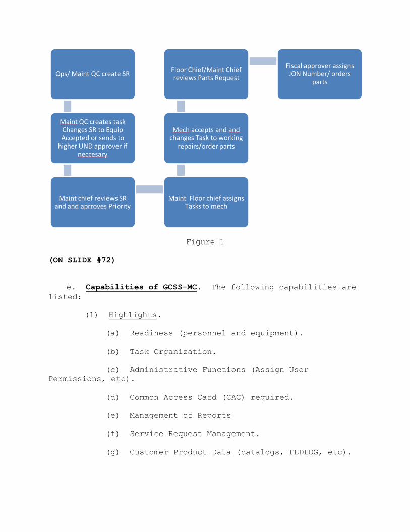
Figure 1
(ON SLIDE #72)
e. Capabilities of GCSS-MC. The following capabilities are
listed:
(1) Highlights.
(a) Readiness (personnel and equipment).
(b) Task Organization.
(c) Administrative Functions (Assign User
Permissions, etc).
(d) Common Access Card (CAC) required.
(e) Management of Reports
(f) Service Request Management.
(g) Customer Product Data (catalogs, FEDLOG, etc).
Ops/ Maint QC create SR
Maint QC creates task Changes SR to Equip Accepted or sends to
higher UND approver if neccesary
Maint chief reviews SR and and aprroves Priority
Maint Floor chief assigns Tasks to mech
Mech accepts and and changes Task to working
repairs/order parts
Floor Chief/Maint Chief reviews Parts Request
Fiscal approver assigns JON Number/ orders
parts

(ON SLIDE #73)
(2) Supply Logistics.
(a) Inventory Management (T/E assets, Operating
Stocks and Demand-supported Items.
(b) Inventory Planning (Quarterly and Annual
Inventories).
(c) Order Management (ensuring the supported units
receive what they need, when they need it).
(ON SLIDE #74)
(3) Maintenance Operations.
(a) Maintenance capacity and fulfillment planning.
(b) Maintenance Operations Scheduling.
(ON SLIDE #75)
(4) Warehouse Management. Inbound items, receipts.
(5) Demand Planning. Demand planning is referred to as
General Package Plus for setting up the ordering of preventive
maintenance kits. Deployment Blocks are commonly referred to as
a class IX block for setting up the ordering of repair parts for
deployment.
(6) Procurement. Procurement to purchase items needed
for supported units.
(ON SLIDE #76)
INTERIM TRANSITION: We have just covered the capabilities of
GCSS-MC, are there any questions? If there are no questions take
a 10 minute break.
(BREAK – 10 Min)
INTERIM TRANSITION: Before the break we discussed the
capabilities of GCSS-MC, now let’s talk about the Universal Work
Que?
________________________________________________________________
________________________________________________________________
________________________________________________________________
(ON SLIDE #77)
f. Purpose of the Universal Work Queue (UWQ). This topic
provides you an overview of the Universal Work Queue (UWQ). The
purpose of the Universal Work Queue is to access, organize, and
act upon different types of work generated in GCSS-MC system.
Work items such as service requests can be accessed by using the
UWQ. You can check all of your assigned service requests and
the status of those service requests.
(ON SLIDE #78)
(1) What is the Universal Work Queue?
(a) The UWQ will contain all your work items.
(b) The content of the UWQ includes the following:
1 View work from several source applications.
2 See counts of workload.
3 Access work assignments directly.
(ON SLIDE #79)
(c) It is important that you “Refresh” your queue to
see the most current work products. From the UWQ screen click >
Tools > Refresh.
(ON SLIDE #80)
(2) Work Type Selector. The Work Type Selector allows
you to navigate to work organized into Queues. It also displays
Counts of work for each queue, allowing you to quickly access
workload.
(ON SLIDE #81)
(a) Node types.

1 Service Request. Total number of service
request in the UWQ.
2 Task. Total created Tasks from the services
request.
3 My Tasks. Total assigned tasks to you.
(b) Work Selector Queues contain nodes and sub-
nodes, which allow you to navigate to specific types of work
quickly.
(c) If your name is in the “Owner” field on a Task
from a given Service Request, then the task would show in “My
Owned”.
(d) If your name is the “Assignee” field from a
given Service Request, then the task would be in the “My
Assigned” section.
(ON SLIDE #82)
(3) Work Summary Panel.
(a) The Work Summary Panel lists work items in
standard row format.
(b) You can view, access, and select an individual
item to work on.
(c) When you select a work item, the appropriate
source form launches for you to act on the work item.
(ON SLIDE #83)
(4) UWQ Tools Menu Options. The following Tools Menu
options are available for the UWQ:
(a) Refresh All Work. Refreshes all data.
(b) Refresh Current Counts. Refreshes counts
data.
(c) Switch display to Cascade. Allows you to
alternate between two UWQ display formats (Hybrid & Cascade).
(5) UWQ Tool Bar Icons. The following Tool Bar Icons
are available for the UWQ:
(a) Refresh Current Counts. Allows you to
refresh all counts and work item in the UWQ.
1 At the start of your session.
2 When you return from a break.
3 After a rush of work.
4 After an hour or two of continuous work.
(b) Switch to Cascade. Switch alternate view.
(c) Get Work. Allows you to open the work item
you have selected in the Work Summary Panel.
(ON SLIDE #84)
(ON SLIDE #85)
g. Purpose of Install Base. Install Base facilitates item
lifecycle management and tracking. Install Base records routine
and detailed information about a particular item instance.
(1) Item Instance. Term used to refer to a single item
and all history associated/ tracked with the item.
(a) Serialized and non-serialized items, PEI
(ON SLIDE #86-87)
(2) Information Available. All parent child
relationships, additional attributes, party relationships,
counters, notes and service requests.
(ON SLIDE #88-89)
(a) Parent/child relationships. For example the
common 24 is a parent of 3 torque wrenches and 1 multimeter.
(ON SLIDE #90-91)

(b) Additional Attributes. This area records all
calibrations information, modification remarks, Preventive
Maintenance scheduling and type and counters.
(ON SLIDE #92-93)
(c) Counters. Lists the type of counters for PMCS
(ON SLIDE #94-95)
(d) Notes. All information that was recorded in
the 696 is annotated there along with acceptance LTI’s.
(ON SLIDE #96-97)
(e) Service Requests/History. Lists all SR’s
opened or closed on that item.
(ON SLIDE #98)
g. Purpose of the User Productivity Kit (UPK). The
purpose of the User Productivity Kit is a collaborative
development environment that provides real simulation of the
GCSS-MC application according to responsibility and functions.
Reinforces training before, during and after GCSS-MC has been
implemented. Practical Applications Activities can utilize UPK
for given system tasks and/or events.
(ON SLIDE #99)
(1) UPK Five Playback Modes.
(a) The 5 available Playback Modes.
1 See It! Mode. This mode enables you to
learn about the selected topic by displaying an animated
demonstration of a task being completed.
2 Try It! Mode. This mode allows you to
perform the selected task in a simulated environment.
3 Know It! Mode. This mode tests your
ability to perform the selected task in the simulated
environment.
4 Do It! Mode. This mode guides you as you
perform the selected task in the live application.
5 Print It! Mode. This mode allows you to
print a topic in Microsoft Word or Adobe PDF format.
INTERIM TRANSISTION: Up to this point we’ve discussed the
purpose of GCSS, the UWQ, and the Install Base/Item Instance. Do
you have any questions? If not, let’s move onto the
demonstration of how to access the Universal Productivity Kit
(UPK).
________________________________________________________________
________________________________________________________________
________________________________________________________________
INTRUCTOR NOTE
Perform the following demonstration.
(ON SLIDE #100-101)
DEMONSTRATION. (30 min) Demonstrate how to access and use GCSS-
MC Online Training UPK. The purpose of this demonstration is to
show students how to access GCSS-MC and look at various
functions in GCSS-MC.
STUDENT ROLE: Students will record the mapping instructions to
gain access to GCSS-MC. Students are to observe the
demonstration only. They are to ask questions or make comments
for clarification. Students will not attempt to perform the
steps along with the instructor.
INSTRUCTOR ROLE: Demonstrate how to gain access to GCSS-MC using
Google.
1. Safety Brief: N/A
2. Supervision and Guidance: Utilize the instructor computer to
display demonstration on the screens. Demonstrate how to access
GCSS-MC Online Training UPK. Demonstrate the application of each
UPK for Universal Work Que and Install Base.
3. Debrief: Allow students the opportunity to ask questions and
comment on the demonstration. Answer student questions and
provide feedback on student comments. Review mapping
instructions for access to GCSS-MC Online Training UPK.
INTERIM TRANSITION: You have just observed a demonstration
covering the UPK, are there any questions? If not, you will
perform a Practical Application.
________________________________________________________________
________________________________________________________________
________________________________________________________________
INTRUCTOR NOTE
Introduce the following Practical Application.
PRACTICAL APPLICATION. (1 hr) Each student will accomplish the
assignment on their own. There is one instructor required Each
student will access and use GCSS-MC Online Training UPK and
perform the “Try it” and “Know it” modes for the following
modules:
CS 101.06.02.02
Maintenance 201.04.02.01 - 201.04.02.03
Maintenance 201.05.02.01 – 201.05.02.04
STUDENT ROLE: Students will log on and perform prac app at their
own pace. When finished they should sit quietly until all the
other students are finished.
INSTRUCTOR ROLE: Instructor should click on Softlink icon in
order to view the student’s progress. This also allows the
instructor to ensure students aren’t viewing other websites and
staying on task.
1. Safety Brief: N/A
2. Supervision and Guidance: Instructor should also walk around
the room and answer questions as they come up.
3. Debrief: Allow students the opportunity to ask questions and
comment on the demonstration. Answer student questions and
provide feedback on student comments.
(ON SLIDE #102-103)
TRANSISTION: Are there any questions over the Practical
Application? If not, I have a couple for you. Q1: What is the
purpose of Global Combat Support System (GCSS-MC)? A1: a
portfolio of near-real time systems that support logistics
elements of command and control, joint logistics
interoperability, and secure access to, and visibility of
logistics data. Q2: What does UPK stand for? A2: User
Productivity Kit. Q3: What is the electronic inbox where request
of services are collected, acted upon, or reassigned to other
users? A3: Universal Work Que Q4: What is the first step when
opening the UWQ? A4: Tools refresh all work. Q5: Why is it
important to refresh your work within the UWQ? A5: So that you
can see the most up to date information. At this time take a ten
minute break.
(BREAK – 10 Min)
TRANSITION: Did anyone think of any questions during the break?
If not, let’s talk about the NAVMC 10560, Worksheet for
Preventive Maintenance and Technical Inspection for Engineer
Equipment?
________________________________________________________________
________________________________________________________________
________________________________________________________________
(ON SLIDE #104)
3. NAVMC 10560, Worksheet for Preventive Maintenance and
Technical Inspection for Engineer Equipment. (30 MIN)
(ON SLIDE #106)
a. Purpose. The purpose of the NAVMC 10560 is to provide a
check list for performing and recording preventive maintenance
checks and services (PMCS) and LTI's (Limited Technical
Inspections), to include acceptance LTI's, LTI's prior to major
repair, and LTI's at the discretion of the Engineer Equipment
officer/chief on Tactical Engineer Equipment and GME Fleet
Managers on Garrison Mobile Engineer Equipment. The NAVMC 10560
is also used as a guide when performing an annual
safety/condition check (ASCC).
Equipment Forms and Records for Equipment on Temporary Loan.
NOTE: TM 4700-15/1_, Chapter 1, pg. 1-5, Para. 1-9.
The owning unit will provide a skeleton equipment record for
the temporary loan of equipment. Temp. Loan in this instance is
considered any short term transfer of equipment from equipment
owner to a temporary holder of the equipment that does not
INSTRUCTOR NOTE
FOUND IN TM 4700-15/1_, pg. 2-22-1

involve a formal transfer of equipment custody: for example, a
command adjustment of allowances. Tag each skeleton equipment
record with the type and due date of the next scheduled
preventive maintenance check and service. The unit borrowing the
equipment will maintain equipment records/skeleton records up-
to-date including entries on all maintenance actions performed.
The borrower will update the Field Maintenance Subsystem (FMSS)
when loaded to the FMSS, or provide the information necessary to
the owning unit to update the FMSS. Upon return of equipment,
the borrowers will return the up-to-date equipment forms and
records containing maintenance actions performed. The lender
will up-date all original records and file the copies of
maintenance actions performed per the instructions contained in
the TM 4700-15/1_. At a minimum, skeleton equipment records will
consist of the joint Limited Technical Inspection performed at
the time of issue to the borrowing unit, and the SL-3 extract
for all SL-3 components temp loaned with the end item.
(ON SLIDE #107-112)
b. Preparation Instructions. The preparing activity may be
the equipment owner, the equipment user; for example, the
equipment is on temporary loan, or the equipment custodian as in
the case of the maintenance section evacuating to the next
higher EOM. The preparing activity is responsible for initial
preparation of the NAVMC 10560. Those items marked with a pound
sign (#) will be completed by the preparing activity.
(1) Section A
(a) Use “SERVICING SYMBOLS” (SS) to list requirements
for PMCS noted in the (SS) column of sections "D" through "M".
(b) Use “LEGEND FOR MARKING” (SS) to list requirements
for CM noted in the (SS) column of sections "D" through "M".
(c) In the “NOMENCLATURE” block, enter the
nomenclature listed on the DATA PLATE.
(d) In the “MAKE” block, enter the make listed on the
DATA PLATE.
(e) In the “MODEL” block, enter the model listed on
the DATA PLATE.
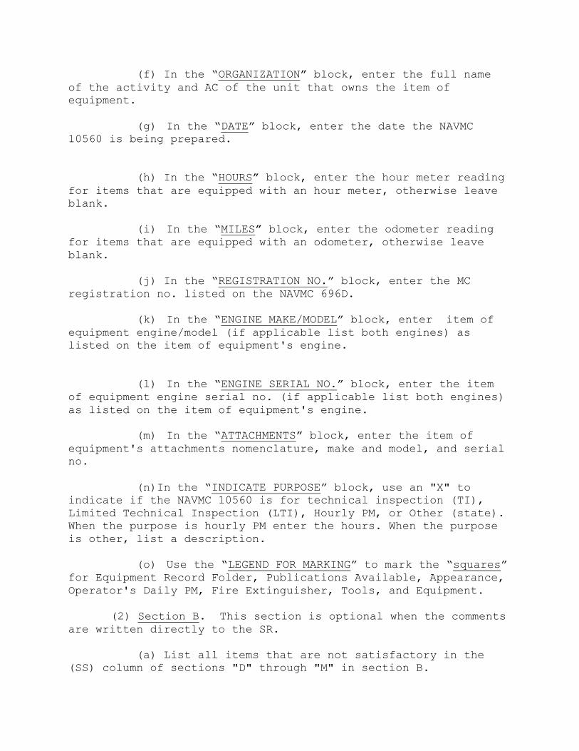
(f) In the “ORGANIZATION” block, enter the full name
of the activity and AC of the unit that owns the item of
equipment.
(g) In the “DATE” block, enter the date the NAVMC
10560 is being prepared.
(h) In the “HOURS” block, enter the hour meter reading
for items that are equipped with an hour meter, otherwise leave
blank.
(i) In the “MILES” block, enter the odometer reading
for items that are equipped with an odometer, otherwise leave
blank.
(j) In the “REGISTRATION NO.” block, enter the MC
registration no. listed on the NAVMC 696D.
(k) In the “ENGINE MAKE/MODEL” block, enter item of
equipment engine/model (if applicable list both engines) as
listed on the item of equipment's engine.
(l) In the “ENGINE SERIAL NO.” block, enter the item
of equipment engine serial no. (if applicable list both engines)
as listed on the item of equipment's engine.
(m) In the “ATTACHMENTS” block, enter the item of
equipment's attachments nomenclature, make and model, and serial
no.
(n)In the “INDICATE PURPOSE” block, use an "X" to
indicate if the NAVMC 10560 is for technical inspection (TI),
Limited Technical Inspection (LTI), Hourly PM, or Other (state).
When the purpose is hourly PM enter the hours. When the purpose
is other, list a description.
(o) Use the “LEGEND FOR MARKING” to mark the “squares”
for Equipment Record Folder, Publications Available, Appearance,
Operator's Daily PM, Fire Extinguisher, Tools, and Equipment.
(2) Section B. This section is optional when the comments
are written directly to the SR.
(a) List all items that are not satisfactory in the
(SS) column of sections "D" through "M" in section B.
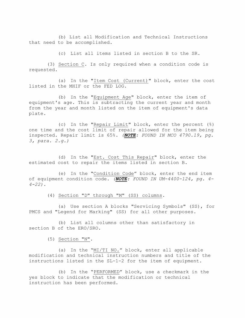
(b) List all Modification and Technical Instructions
that need to be accomplished.
(c) List all items listed in section B to the SR.
(3) Section C. Is only required when a condition code is
requested.
(a) In the "Item Cost (Current)" block, enter the cost
listed in the MHIF or the FED LOG.
(b) In the "Equipment Age" block, enter the item of
equipment's age. This is subtracting the current year and month
from the year and month listed on the item of equipment's data
plate.
(c) In the "Repair Limit" block, enter the percent (%)
one time and the cost limit of repair allowed for the item being
inspected. Repair limit is 65%. (NOTE: FOUND IN MCO 4790.19, pg.
3, para. 2.g.)
(d) In the "Est. Cost This Repair" block, enter the
estimated cost to repair the items listed in section B.
(e) In the “Condition Code” block, enter the end item
of equipment condition code. (NOTE: FOUND IN UM-4400-124, pg. 4-
4-22).
(4) Section "D" through "M" (SS) columns.
(a) Use section A blocks "Servicing Symbols" (SS), for
PMCS and "Legend for Marking" (SS) for all other purposes.
(b) List all columns other than satisfactory in
section B of the ERO/SRO.
(5) Section "N".
(a) In the “MI/TI NO.” block, enter all applicable
modification and technical instruction numbers and title of the
instructions listed in the SL-1-2 for the item of equipment.
(b) In the “PERFORMED” block, use a checkmark in the
yes block to indicate that the modification or technical
instruction has been performed.

(c) In the “PERFORMED” block, use a check mark in the
no block to indicate that the modification or technical
instruction has not been performed.
(6) Section "O" is self explanatory.
(7) Section "P".
(a) In the "Mechanic/Operator (Name, Grade,
Organization)" block, enter the name, grade, and organization of
the person preparing sections "B" through "M".
(b) In the "Maintenance/Operations Chief (Name, Grade,
Organization)" block, enter the name, grade, and organization of
the maintenance/operations chief of the mechanic/operator listed
in the "Mechanic/Operator (Name, Grade, Organization)" block of
section P.
1 In the "ERO No." block, enter the SR number.
2 In the "Date" block, enter the date the SR was
assigned.
3 In the "Maintenance/Operations Officer As
Required (Name, Grade, Organization)" block, enter the name,
grade, and organization of the maintenance/operations officer.
4 In the "Responsible Officer As Required (Name,
Grade, Organization)" block, enter the name, grade, and
organization of the responsible officer.
5 Tactical Engineer Equipment. For Tactical
Engineer Equipment, use the Service Request in conjunction with
NAVMC 10560 to record all PMCS and CM performed and the Parts
Requirements to request parts.
(ON SLIDE #113)
(8) Filing and Disposition. When the maintenance
officer/chief has verified that all requirements listed in
section B of the worksheet have been transferred to a Service
Request, the NAVMC 10560 will be destroyed. Retain any NAVMC
10560 used in conjunction with an investigation until released
from investigation. Treat a NAVMC 10560 released from
investigation as CM.

(9) Responsibilities for Tactical Engineer Equipment. The
equipment chief is responsible for preparing the worksheet for
the PMCS. Prepare a template indicating the required PMCS for
each item of equipment to facilitate the preparation. When
preparing the template, refer to the appropriate services listed
in the TM's, Army Technical Bulletins, and other publications
applicable to the equipment. Comparing the template for the
specific item of equipment with the blank form NAVMC 10560, non-
applicable portions of the form may be blanked out. The
worksheet which indicates the required services is then turned
over to the maintenance unit. The maintenance unit, with the
assistance of the operator, performs the required services and
signs the worksheet indicating that the service has been
completed. The equipment chief will also ensure that equipment
requiring repairs is inspected and the results of the inspection
are recorded on the form NAVMC 10560 worksheet before the
equipment is repaired.
ITERIM TRANSISTION: We’ve just covered the preparation
instructions and filing/dispostion of the NAVMC 10560, are there
any questions? If not, let’s move into the practical application
of performing an LTI.
________________________________________________________________
________________________________________________________________
________________________________________________________________
INTRUCTOR NOTE
Introduce the following Practical Application. Have students
take breaks as required.
(ON SLIDE #114)
PRACTICAL APPLICATION. (1 HR)Pass out NAVMC 10560. Split the
class into four equal groups and assign each a specific item of
equipment. The purpose of this Practical Application is to
properly conduct a Limited Technical Inspection. Normal class
size is 25. There is one instructor required for this evolution.
PRACTICE: Students will use their NAVMC 10560 and perform an LTI
on equipment that is located at the rear of Brown Hall.
Safety Brief: Three points of contact while climbing in/around
equipment.
Supervision and Guidance: Instructor is moving around the lot,
assisting students, and answering questions as they arise.

Debrief: PEI major discrepancies will be briefed.
TRANSISTION: We’ve just completed the LTI practical application,
are there any questions? If not, I have several for you.Q1: What
is the purpose of the NAVMC 10560? A1: To provide a check list
for performing and recording preventive maintenance checks and
services (PMCS) and LTI's (Limited Technical Inspections) Q2: Is
the NAVMC 10560 used for ASCC’s? A2: Yes Q3: Who is responsible
for ensuring Mods has been performed during the LTI? A3: QC. At
this time take a ten minute break.
(BREAK – 10 Min)
TRANSITION: Did anyone think of any questions during the break?
If not, let’s talk about the Corrective Maintenance Service
Request.
________________________________________________________________
________________________________________________________________
________________________________________________________________
(ON SLIDE #117)
4. CORRECTIVE MAINTENANCE SERVICE REQUEST. (1 Hr 30 MIN)
a. Preparation, Filing, and Disposition of a Service
Request (SR).
(ON SLIDE #118)
(1) Purpose of a Service Request (SR). A service
request is the foundation of all activities within GCSS-MC. The
GCSS-MC maintenance SR will be used in place of NAVMC 10245 in
all instances of maintenance that require Modification,
Calibration, Corrective Maintenance, Preventive Maintenance
Checks and Services (PMCS), Collateral Equipment (sl-3)
replenishment, and Limited Technical Inspections on ground
equipment managed within GCSS-MC.
(ON SLIDE #119)
(a) A task will be created for each defect
identified during the acceptance LTI and during the conduct of
maintenance.
(ON SLIDE #120)
(b) GCSS-MC functionality requires a SR to be
opened in any instance where parts are applied. A SR is not
required in instances where labor is less than .3 hours and no
parts are applied. Separate service requests are required for
Calibration, Corrective Maintenance, PMCS, Modification or
Limited Technical Inspections.
(ON SLIDE #121)
(c) A SR may have different priority tasks. If a
task is created or upgraded to a higher priority than the SR,
GCSS-MC will provide a warning that the SR will also be upgraded
and may require a work re-approval.
(ON SLIDE #122-123)
(d) Inter-shop repairs for the child of a PEI
(ex. HMMWV component for MRC) will be accomplished by opening a
parent SR (ex. SR for TAMCN A0067) and a child SR for the HMMWV.
Parent and child SR must be linked. The child SR owning group
will be changed to reflect the group performing repairs (ex.
MXXXXX_MT) and the status will reflect “INTER-SHOP RPR”. The
group performing the repair on the child will change the status
of the SR to equip accepted. If it becomes necessary for the
child to be evacuated to a supporting maintenance activity, the
child SR will be copied.
(ON SLIDE #124)
(2) Responsibilities.
(a) Preparing Activity. The preparing activity may
be the equipment owner, equipment user (temp loan) or equipment
custodian (maintenance section) as in the case of the
maintenance section evacuating equipment to a supporting
organization with the appropriate maintenance capability.
(ON SLIDE #125-129)
(b) At a minimum the following data elements will
be captured on the SR:
1 Contact Information. Input the individual
to be contacted upon completion of repairs.
2 Serial/Item Instance Number. Input the
serial or item instance number, which requires repair, and ‘tab’
from that field. This action will auto-populate the customer,
TAMCN/ID/MODEL, NIIN, and description fields.
3 Service Request Type. Select the
appropriate maintenance request type from the drop down menu.
Ensure only one SR of each maintenance request type is open on a
specific item of equipment at each maintenance activity.
4 Status. Select the appropriate status of
the SR i.e. SHT PRT, SHT FND, Equip Accept.
(ON SLIDE #130)
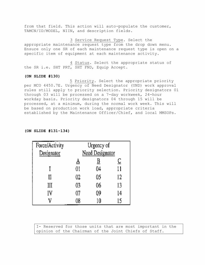
5 Priority. Select the appropriate priority
per MCO 4450.7E. Urgency of Need Designator (UND) work approval
rules still apply to priority selection. Priority designators 01
through 03 will be processed on a 7-day workweek, 24-hour
workday basis. Priority designators 04 through 15 will be
processed, at a minimum, during the normal work week. This will
be based on production work load, appropriate criteria
established by the Maintenance Officer/Chief, and local MMSOPs.
(ON SLIDE #131-134)
I- Reserved for those units that are most important in the
opinion of the Chairman of the Joint Chiefs of Staff.

II- OCONUS or deployed or planning to deploy within 30
days.
III- CONUS
IV- Marine Forces Reserve units.
V- The Marine Corps Exchange (MCX)
Urgency of Need Designator A - Item must be dead lined
combat essential equipment.
Urgency of Need Designator B – Item is degraded
Urgency of Need Designator C – Routine or on schedule
repairs, maintenance, and replacement.
(ON SLIDE #136-137)
6 Echelon of Maintenance. Select the
appropriate echelon of maintenance conducting repairs.
(ON SLIDE #138-139)
7 Group. Input the resource group conducting
repairs.
8 Problem Summary. This is a free text field.
Keep the problem summary clear and concise.
9 Problem Codes. These are synonymous with
legacy defect codes and appear on the maintenance production
report.
10 Operational Status. Assign the appropriate
operational status. Note that ‘deadlined’ status will auto-
populate the deadline control date (DCD) field in the header of
the SR upon this assignment.
11 Notes. Use the notes to add any
relevant/additional information.
(ON SLIDE #140)
(3) Maintenance Activity.
(a) Upon receipt of a SR, the maintenance activity
will validate the information contained on the SR compared to
the actual equipment inducted into maintenance. The maintenance
activity will utilize the SR notes to record information
validated during induction (also referred to as an “acceptance
inspection”). Examples of information to be validated will
include, but are not limited to, the following:
(ON SLIDE #141)
(b) Each SL-3 component accepted will be listed. If
all SL-3 items are accepted, a statement of ‘accepted SL-3
complete’ will be entered.
(c) Visual defects will be listed on the SR. If
there are no visual defects, a statement of “no visual defects”
will be entered.
(d) The operator/crew PMCS condition of the
equipment will be annotated.
(ON SLIDE #142)
(e) If the SR has not been properly completed per
the GPN 1-13, reassign the SR to the preparing activity and
notify them to take corrective action as necessary. Coordination
shall be made between the preparing activity and the supporting
maintenance activity to ensure required services are provided.
(ON SLIDE #143)
(f) The maintenance activity will change the status
of the SR to ‘Equip Accepted,’ save the SR and print a copy of
the equipment’s transfer of custody report and provide it to the
preparing activity. Accomplishment of this step will auto-
populate the date received in shop (DRIS). This action will be
completed prior to the maintenance activity performing further
steps in the maintenance cycle.
(ON SLIDE #144-147)
(g) The maintenance section will accomplish all
repairs within its authorized maintenance capability and record
that information in the SR for each task created.
(h) Labor debrief. Record actual time expended in
the performance of maintenance for the assigned task on the
‘labor’ tab of the task debrief.
(i) Materiel debrief. Record all materiel, including
Demand-supported Items, scrounge, broken unit of issues (BUI),
and parts ordered, for the assigned task on the ‘materiel’ tab
of the task debrief.
(ON SLIDE #148)
(j) Ensure job status codes are applied to the SR
and properly reflect the actual status of the equipment
throughout the maintenance cycle.
INTERIM TRANSITION: Are there any questions on what we just
covered? If not lets take a break.
________________________________________________________________
________________________________________________________________
________________________________________________________________
(BREAK 10 MIN)
INTERIM TRANSITION: Did anyone think of any questions during
the break? If not, let’s move on.
________________________________________________________________
________________________________________________________________
________________________________________________________________
(k) Removing equipment from a deadlined status and
closing the service request. The following steps apply when
equipment has been repaired to the extent that it is no longer
deadlined or all repairs have been completed.
(4) Debrief all deadlining parts.
(a) Debrief all labor hours within each completed
task to record actual labor hours incurred then set the status
of the task to closed, click save.
(b) If additional repairs are outstanding but the
item is no longer deadlined, the operational status of the SR
will update automatically based on the assigned operational
status of remaining task(s). The maintenance activity will
ensure each maintenance action required is captured in a task
and assigned the appropriate operational status. Legacy category
codes have been replaced by the operational status.
(ON SLIDE #149)

(c) The maintenance activity will perform quality
control measures to ensure the equipment is operational,
modifications are verified, and all parts requirements are
debriefed within each respective task. A statement of “repairs
inspected, MODS verified, QC complete” will be entered in a task
for final insp. At that time, the maintenance activity will
create an owner notified task and submit to the preparing
activity. If the preparing activity is not satisfied that all
requested services have been properly performed and all
maintenance tasks have been “closed”, the maintenance activity
will resolve any issues to ensure the customer receives the
requested support.
(d) Equipment counters will be updated with the
current counter reading at the time the SR is being closed.
Prior to closure of a SR, the Maintenance Officer/Chief will
verify entries for work performed.
(ON SLIDE #150)
(e) Once satisfied that all requested support has
been properly provided, the preparing activity will recover all
equipment submitted for service. The preparing activity will set
the SR to “closed”, a dialog box will appear indicating the
item’s operational status will be set to ‘OPERATIONAL-NO SR’ if
all service requests are closed or cancelled. Click ‘ok’ to
accept. A copied/courtesy SR will be closed by the maintenance
activity conducting repairs.
(ON SLIDE #151)
(5) Filing and Disposition. Maintenance history captured
on the SR will remain associated to the item instance/serial
number for the life of the item’s instance under service
history. As a result, activities are no longer required to print
paper copies of service requests to file in the equipment record
jacket or NAVMC 696D. MCO 4400.16H mandates the use of GCSS-MC
for various form’s that are functionally incorporated and also
allows for non-system maintenance documentation to be uploaded
to the equipment item instance. These documents can be either
scanned copies or electronically formatted forms.
(a) The intent is to capture required maintenance
documentation in GCSS-MC. In the event that required maintenance
documentation cannot be uploaded, units are required to retain
hardcopy maintenance documentation until it can be successfully
loaded into GCSS-MC or until such time as the required document
retention period has elapsed.
(b) Commanders may utilize a 696D, or commodity
equivalent, for document retention in those instances where
loading non-system documentation is not presently feasible.
(ON SLIDE #152)
b. Types of Service Requests.
(1) Service. This involves the request for support
(2) Maintenance. This involves the repair of an end
item and request replacement parts.
(3) Supply. This involves the ordering of parts or end
items.
(ON SLIDE #153-154)
c. Flow of a Service Request. The process flow of a SR
varies with the type of SR and MMSOP. In general the flow is as
follows:
(1) Requestor. The one requesting a service to be
accomplished
(2) Capacity Manager. This individual evaluates the SR
and approves the service
(3) Production Manager. This individual tasks out the
work to the executor
(4) Executor. This is the individual performing the
work.
(ON SLIDE #155-156)
d. Creation of a SR . Once a new service request is
opened, the fields highlighted in yellow indicate required
information to be inputted.
(1) Contact Type.
(2) Customer Type.
(3) Name.
(4) Type.
(5) Status.
(6) Priority.
(7) Problem Summary.
(8) Operational Status.
(ON SLIDE #158-159)
e. Request Work In The Service Request.
(1) Tasks. The task tab is used by the production
manager to setup and assign tasks for workers to perform. After
a task is opened, the fields highlighted in yellow indicate
required information to be inputted.
(a) Type.
(b) Status.
(c) Priority.
(d) Owner Type.
(e) Owner.
(f) Start Planned Date.
(g) End Planned Date.
(h) Planned Effort.
(i) Subject
(ON SLIDE #160-179)
(2) Close Service Request.

(a) Task Debrief. The task debrief form allows
the labor and material to be recorded.
1 Service Activity Code.
2 Duration.
3 Service Start Date.
4 UOM.
5 NIIN.
6 Qty.
7 Org.
8 Locator.
9 Serial Number
10 Lot
11 Service Date
12 WRS
(b) Close Out Service Request. A service
request can only be closed once all of the tasks have been
completed.
(ON SLIDE #180-184)
(c) Evac Higher Echlon. Copying a SR is required
for inter-shop repairs and evacuation requirements. The
preparing activity is responsible for creating the copied SR and
for linking the copied SR to the original SR by use of the
‘RELATED OBJECTS’ tab.
TRANSISTION: We’ve just covered the Corrective Maintenance SR,
are there any questions? If not, I have several for you. Q1:
What is the purpose of a Service Request? A1: Maintenance SR
will be used in all instances of maintenance that require
Modification, Calibration, Corrective Maintenance, Preventive
Maintenance Checks and Services (PMCS), Collateral Equipment
(sl-3) replenishment, and Limited Technical Inspections on
ground equipment Q2: What will be created for each defect
identified during the acceptance LTI? A2: A task Q3: If a task
is created or upgraded to a higher priority than the SR, and
priority goes beyond the users UND authority what must happen?
A3: SR must be forwarded to an individual with proper UND
authority for approval and digital signature. Q4: If a piece of
equipment is running Priority 02, what F/AD and UND is it in?
A4: FADII and UND A. At this time take a ten minute break.
________________________________________________________________
________________________________________________________________
________________________________________________________________
(BREAK – 10 Min)
TRANSITION: Did anyone think of any questions during the break?
If not, let’s talk about Parts Requirement.
________________________________________________________________
________________________________________________________________
________________________________________________________________
(ON SLIDE #188)
5. Parts Requirement (20 MIN)
(ON SLIDE #189)
a. Purpose. The GCSS-MC parts requirement form on a task
eliminated the EROSL as a MIMMS data entry form and item/parts
requisitioning document. Maintenance management information is
entered directly into GCSS-MC. Associated item/parts
requisitioning are achieved within GCSS-MC by identifying
required materials in a parts requirement form.
(1) Functionality. The parts requirement form is an
element of a service request task. Priorities from a service
request task are auto populated onto the parts requirement form.
If a service request task is upgraded to a higher priority,
GCSS-MC will provide a warning that the service request will
also be upgraded and will require a work re-approval.
INSTRUCTOR NOTE
A priority upgrade/downgrade of a task does not automatically
upgrade/downgrade the associated open requisitions previously
submitted on the parts requirement form. The maintenance
commodity must request that the units supply section access
document management in order to modify the priorities of the
requisitions.
(ON SLIDE #190-197)
(2) Preparation Instructions. The individual steps and
procedures for properly creating a service request parts
requirement task are available through the User Productivity Kit
(UPK), GCSS-MC scheduled training, and the training provided on
the GCSS-MC web site titled "on line training".
INSTRUCTOR NOTE
The UPK training module incorrectly directs' the user to open a
separate supply task for submission of a parts requirement.
Parts requirements must be made under the associated maintenance
task in order to properly populate an operational status to the
maintenance task. It is not possible to populate an operational
status to a supply task.
(ON SLIDE #198-209)
(3) Advice Codes/Job Order Numbers (JON)/Required
Delivery Dates (RDD)/Signal Codes and NMCS indicators. These
date elements are still used within GCSS-MC. Users will refer to
references A through E, and local SOPs for application of these
data points.
INSTRUCTOR NOTE
NMCS indicators do not currently have a data entry field in
GCSS-MC. However, NMCS indicators of n or e may be entered in
the RDD field per REFs B and E. In no instance will the RDD
field be left blank.
(a) When the equipment undergoing repairs is, in
the opinion of the CO, mission essential impacting unit
readiness, and the part being ordered is required to remove the
equipment form an NMCS status or ANMCS status, use the NMCS
indicators as follows:

1 Use a “9” for each NMCS requirement when
the priority designator is a 01, 02, or 03 for an overseas
customer or stateside customer deploying overseas within 30
days.
2 Use a “N” for each NMCS requirement when
the priority designator is 02, 03, 04, 05, 06, 07, or 08 for a
stateside customer.
3 Use an “E” for each ANMCS requirement when
the priority designator is 02, 03, 04, 05, 06, 07, or 08.
4 This field will be left blank when the
part does not place the equipment into a NMCS or ANMCS status.
(ON SLIDE #210-215)
(4) Special Instructions.
(a) Funding Approvals. Once the parts requirement
has been verified as funds available by the fiscal approver; the
fiscal approver will submit the requisitions via the “create
order” button on the parts requirement form. Only those
individuals with authority to commit funds have access to the
create order button. If the fiscal approver rejects the parts
requirement, they must notify the requestor. An explanation will
be entered into the notes field of the service request citing
reason for disapproval. If the disapproval is based on short
funds, the service request owner will change the status of the
service request to SHT FUNDS and save.
(ON SLIDE #216-225)
(b) Material Debrief. Items in the maintenance
commodity stage sub inventory will be electronically transferred
into the layette sub inventory/locator. The maintenance
commodity section will debrief parts from the layette sub
inventory/locator as they are applied in support of the
maintenance task. All parts must be properly debriefed prior to
the closure of a service request.
(c) Filing. Parts requirement history captured by
GCSS-MC will remain attached to the PEI instance data for the
life of the equipment. This eliminates the requirement to file
paper copies in the equipment records.

ITERIM TRANSISTION: We’ve just covered the procedures for
requesting parts, are there any questions? If not, let’s move
into the practical application of requesting parts utilizing the
UPK.
________________________________________________________________
________________________________________________________________
________________________________________________________________
INSTRUCTOR NOTE
Introduce the following Practical Application. Students will
take breaks as required.
(ON SLIDE #226)
PRACTICAL APPLICATION: (2 HRS)
The purpose of this practical application is to allow the
students to familiarize themselves with the UPK, open a SR,
close a SR and requisition parts in the “Try it” and “Do it”
modes. Student instructor ratio is 25:1. The following UPK
modules will be covered:
Ser 101.02.02.01 – 101.02.02.05
Maint 101.04.02.01 – 101.04.02.08
STUDENT ROLE: Students will log on and perform prac app at their
own pace. When finished they should sit quietly until all the
other students are finished.
INSTRUCTOR ROLE: Instructor should click on Softlink icon in
order to view the student’s progress. Instructor should patrol
the classroom to ensure students are on the correct web page and
staying on task. Answer any questions or concerns that arise
IRT GCSS-MC and the UPK.
1.Safety Brief: N/A.
2.Supervision and Guidance: Instructor will patrol the
classroom to answer any questions and ensure students are not
moving onto other Practical Application UPK.
3.Debrief: After the practical application ask the students if
there are any questions and probe the class to ensure
understanding before moving on.
TRANSISTION: We’ve just covered the Parts Request, are there any
questions? If not, I have several for you.Q1: When will parts be
debriefed in GCSS-MC? A1: Debrief parts from the layette sub

inventory/locator as they are applied in support of the
maintenance task. Q2: Who approves the requisition once funds
have been verified? A2:Fiscal Approver At this time take a 10
minute break.
________________________________________________________________
________________________________________________________________
________________________________________________________________
(BREAK – 10 Min)
TRANSITION: Did anyone think of any questions during the break?
If not, let’s talk about the SF 368, Product Quality Deficiency
Report and Modifications.
________________________________________________________________
________________________________________________________________
________________________________________________________________
(ON SLIDE #253)
7. SF 368, Product Quality Deficiency Report and MODS. (50MIN)
(ON SLIDE #254)
a. Purpose. The SF 368, (Product Quality Deficiency Report
(PQDR)) provides information to activities responsible for
development, procurement, or management of equipment concerning
deficiencies in material, design, or procurement.
b. Objective. The primary goals of the PQDR program are to
maximize mission and operational effectiveness, prevent
recurring deficiencies, and improve user satisfaction with
Marine Corps material.
(1) Provide a user product quality deficiency
reporting and a data feedback system that provides for
appropriate documentation, action/resolution, and specific
points of contact for all phases of the PQDR processing.
(2) Provide for analysis and investigation of PQDR’s
in a timely manner for expedient corrective and preventive
actions.
(3) Provide for control and disposition of deficient
material.

(4) Maintain a system that affords management with
visibility of PQDR summary data, identification of problems,
recurring deficiencies, and resolution/corrective actions.
c. Policy. Equipment having deficiencies that meet the
reporting criteria for a PQDR will be reported and processed
using the MCO 4855.10_. Additionally, investigation into and
resolution of these reporting deficiencies will be expedient and
field activities will be notified of the corrective actions.
(ON SLIDE #255)
d. Action. Qualifications and procedures for the
processing of PQDR’s are as follows:
(1) The PQDR process begins with the user/originator
reporting the material deficiency to the originating point.
(a) User/Originator is the person who becomes
aware of a defect or deficiency and repots it to the originating
point.
(b) Originating Point is the unit that finds a
product quality deficiency and reports it to the screening
point.
(c) The term “Screening Point” is defined as
Commander, Marine Corps Logistics Command, Albany, GA.
(2) A PQDR shall be submitted as a result of any of
the circumstances listed below:
(a) A physical or operational condition considered
to constitute a hazard to personnel or material.
(b) A design of items or components, which impedes
the proper operation, maintenance, or handling of the material
or item.
(c) Faulty material or poor workmanship.
(d) Excessive wear or deterioration for the period
of time and for the conditions under which the item was in use
or on hand.
(e) Operation or performance of equipment in the
course of normal operations that fail to meet stated operational
limits.
(f) Circumstances other than those indicated, but
considered to be related to deficiencies in material quality and
not meeting the reporting criteria for other programs that are
listed in MCO 4855.10_ Encl. 2.
(g) As a result of tactical systems computer
software/firmware and documentation deficiencies.
(h) On items known to be under warranty as
specified by the special instructions contained in the Users
Logistics Support Summary (ULSS) or Supply Instruction (SI).
(3) Reporting Responsibility Procedures.
(a) The individual who discovers the product
quality deficiency shall submit a PQDR (SF 368) and report it to
the Battalion, Squadron, or Company (Originating Point).
(b) The originating point shall check to ensure
the PQDR is valid with the criteria set forth in the MCO
4855.10_, and assign one of the levels of severity categories,
Category I or II.
(c) Category I Deficiency. Is a product quality
deficiency that may cause death, injury, or severe occupational
illness; would cause loss of or major damage to a weapon system;
directly restricts the combat readiness capabilities of a using
organization; or which would result in a production line
stoppage.
1 Suspend the use of deficient material to
include any of the material in stock. Maintain exhibits until
the screening point calls for the material or for 60 days from
receipt of the control number from the screening point.
2 When the urgency exists, Cat. I PQDR’s may
first be transmitted by oral communication. The phone number for
this is DSN 567-5291 or Comm. (912) 439-5631. This must be
followed up electronically by priority message, E-Mail using the
SF 368 message, E-Mail format, or electronic fax to the
Commander (Code 808-1), MCLB, Albany, GA within 48 hours of the
message only when supporting documents will aid the
investigation. The SF 368 shall be prepared in triplicate and
shall contain the DTG (Date, Time, Group), and the same report
number used in the message.
(d) Category II Deficiency. Is a product quality
deficiency that does not meet the criteria set forth for
Category I.
1 Suspend the use of the item or material
as necessary.
(e) For all PQDR Categories.
1 Maintain exhibits until the screening
point calls for the material or for 60 days from receipt of the
control number from the screening point.
2 Submit exhibits for individual clothing
on an “as required” basis as required by the screening point.
3 Forward one information copy of each PQDR
involving tactical digital systems computer software, firmware,
and/or documentation deficiencies to the Commanding Officer,
Marine Corps Tactical System Support Activity, Camp Pendleton,
CA 92055-5130.
4 The supporting maintenance activity will
assist in the analysis and failure documentation prior to
submission of the PQDR, when material deficiencies cannot be
appropriately analyzed at a given user/maintenance level.
a Report any deficient PQDR responses
to Commander (Code 808-1), MCLB Albany, GA 31704-5000 (screening
point), for corrective action.
b Maintain a status log on all PQDR’s
submitted through final action, noting final action taken, and
maintain a copy of the finalized PQDR for a period of 1 year
following final action per SECNAVINST P5212.5_.
c Report items known to be under
warranty on the SF 368 per the implementing warranty clauses of
the Users Logistics Support Summary (ULSS) or Supply Instruction
(SI).
(ON SLIDE #256-257)
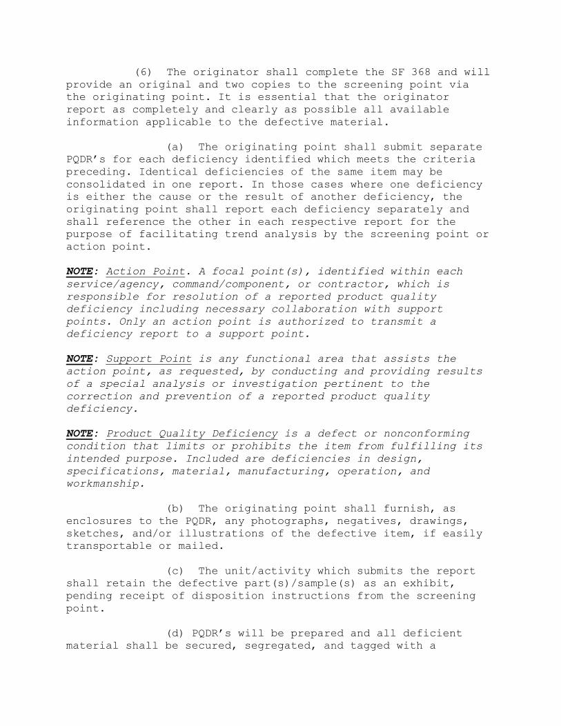
(6) The originator shall complete the SF 368 and will
provide an original and two copies to the screening point via
the originating point. It is essential that the originator
report as completely and clearly as possible all available
information applicable to the defective material.
(a) The originating point shall submit separate
PQDR’s for each deficiency identified which meets the criteria
preceding. Identical deficiencies of the same item may be
consolidated in one report. In those cases where one deficiency
is either the cause or the result of another deficiency, the
originating point shall report each deficiency separately and
shall reference the other in each respective report for the
purpose of facilitating trend analysis by the screening point or
action point.
NOTE: Action Point. A focal point(s), identified within each
service/agency, command/component, or contractor, which is
responsible for resolution of a reported product quality
deficiency including necessary collaboration with support
points. Only an action point is authorized to transmit a
deficiency report to a support point.
NOTE: Support Point is any functional area that assists the
action point, as requested, by conducting and providing results
of a special analysis or investigation pertinent to the
correction and prevention of a reported product quality
deficiency.
NOTE: Product Quality Deficiency is a defect or nonconforming
condition that limits or prohibits the item from fulfilling its
intended purpose. Included are deficiencies in design,
specifications, material, manufacturing, operation, and
workmanship.
(b) The originating point shall furnish, as
enclosures to the PQDR, any photographs, negatives, drawings,
sketches, and/or illustrations of the defective item, if easily
transportable or mailed.
(c) The unit/activity which submits the report
shall retain the defective part(s)/sample(s) as an exhibit,
pending receipt of disposition instructions from the screening
point.
(d) PQDR’s will be prepared and all deficient
material shall be secured, segregated, and tagged with a
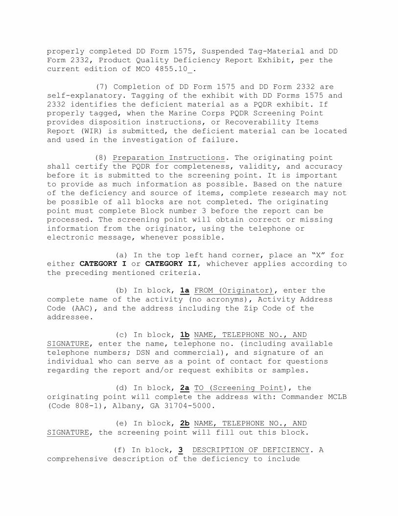
properly completed DD Form 1575, Suspended Tag-Material and DD
Form 2332, Product Quality Deficiency Report Exhibit, per the
current edition of MCO 4855.10_.
(7) Completion of DD Form 1575 and DD Form 2332 are
self-explanatory. Tagging of the exhibit with DD Forms 1575 and
2332 identifies the deficient material as a PQDR exhibit. If
properly tagged, when the Marine Corps PQDR Screening Point
provides disposition instructions, or Recoverability Items
Report (WIR) is submitted, the deficient material can be located
and used in the investigation of failure.
(8) Preparation Instructions. The originating point
shall certify the PQDR for completeness, validity, and accuracy
before it is submitted to the screening point. It is important
to provide as much information as possible. Based on the nature
of the deficiency and source of items, complete research may not
be possible of all blocks are not completed. The originating
point must complete Block number 3 before the report can be
processed. The screening point will obtain correct or missing
information from the originator, using the telephone or
electronic message, whenever possible.
(a) In the top left hand corner, place an “X” for
either CATEGORY I or CATEGORY II, whichever applies according to
the preceding mentioned criteria.
(b) In block, 1a FROM (Originator), enter the
complete name of the activity (no acronyms), Activity Address
Code (AAC), and the address including the Zip Code of the
addressee.
(c) In block, 1b NAME, TELEPHONE NO., AND
SIGNATURE, enter the name, telephone no. (including available
telephone numbers; DSN and commercial), and signature of an
individual who can serve as a point of contact for questions
regarding the report and/or request exhibits or samples.
(d) In block, 2a TO (Screening Point), the
originating point will complete the address with: Commander MCLB
(Code 808-1), Albany, GA 31704-5000.
(e) In block, 2b NAME, TELEPHONE NO., AND
SIGNATURE, the screening point will fill out this block.
(f) In block, 3 DESCRIPTION OF DEFICIENCY. A
comprehensive description of the deficiency to include

circumstances prior to the failure. Explain, to the best of your
ability, what is wrong with the item. Explain how the item does
not function with relating parts or assemblies. Include specific
drawings, specifications, regulations, instructions, or
contracts. If an item is dimensionally incorrect, list the
actual dimensions as well as the source of the correct
dimensions (tech manual/drawing or comparative measurement of
the old item). As best as you can, also include the following: ·
Condition of packaging when received.
1 Condition of part when removed from
packaging.
2 Was defect discovered prior to or after
installation?
3 How was deficiency discovered?
4 How was deficiency confirmed?
5 Were there any ID markings or stamps on
deficient item?
6 Were serviceable tags attached or
available when item was received?
7 Are pictures of the defective item
available?
8 Describe or identify any tests or
procedures used during installation and/or testing.
9 Identify (by RCN) any previous related (by
NSN or defect) PQDRs that you know of or have submitted.
(9) In block, 4 DATE DEFICIENCY DISCOVERED, enter the
calendar date on which the deficiency was discovered.
(10) In block, 5 NATIONAL STOCK NUMBER (NSN), enter
the NSN of the deficient material. No NSN enter the Part Number.
(11) In block, 6 NOMENCLATURE, enter the noun name of
the material to be found deficient.
(12) In block, 7 OPERATING TIME AT FAILURE. Time item
had been in operation since new, overhauled, or repaired when
the deficiency was discovered citing the appropriate performance
element (miles, cycles, hours etc.). Enter "Initial” if the

deficiency occurred with no operation time since new,
overhauled, or repaired.
(13) In block 8 DEFICIENT ITEM PART NUMBER - The
manufacturer's part number of the deficient item. This number
may be found on the item or package markings.
(14) In block 9a MANUFACTURER'S CAGE CODE A five
digit Contract and Government Entity (CAGE) Code of the
manufacturer (of the deficient item) as listed in the DLA
Cataloging Handbook H4.1 (Name to code), Federal Supply Code for
manufacturer (United States and Canada). The CAGE Code may be
taken from the markings on the deficient item. NOTE: If the
deficient item was repaired or overhauled, the CAGE or DODAAC of
the last repair/ overhaul facility shall be entered in Block
12c.
(a) In block 9b MANUFACTURER / CITY / STATE -
Name and address of the manufacturer which manufactured,
repaired or overhauled the deficient item. For motor vehicles or
components thereof, enter name of manufacturer of the vehicle or
component, as appropriate.
(15) In block 10, QUANTITY
(a) RECEIVED - Enter the total number of items or
parts received.
(b) INSPECTED - Enter the total number of items
inspected.
(c) DEFICIENT - Enter the quantity found
deficient of those inspected.
(d) IN STOCK - Enter the quantity of additional
material from the same manufacturer and contract remaining in
stock.
(16) In blocks 11 SERIAL / LOT / BATCH NUMBER - Enter
the manufacturer's serial, lot, or batch number of the deficient
items as applicable. If any of these are unknown or don't apply,
check the respective boxes for Unknown or N/A. If multiple
numbers are reported, provide additional numbers in Description
of Deficiency, Block 3.
(17) In block 12a ITEM - Check the appropriate block
to indicate whether the deficient item is New, Repaired, or

Overhauled. Provide the dates manufactured, repaired, or
overhauled in Block 12b, if available.
(a) In block 12b DATE MANUFACTURED, REPAIRED, OR
OVERHAULED - Enter the date the deficient item was manufactured
if New item was selected in 12a, and the date repaired or
overhauled if so selected in 12a.
(b) In block 12c LAST REPAIR FACILITY - If the
deficient item was repaired or overhauled, enter the CAGE or
DODAAC, name, and address of the Repair Facility which last
repaired or overhauled the deficient item.
(18) In block 13a CONTRACT NUMBER - This is the
identification number of the contract under which the deficient
item/commodity was purchased or reworked. The number is
comprised of Contract activity's Department of Defense Activity
Address Code 6 position (DODAAC) example (N00024), seven
position Contract Serial example (99C0001) Number, and 4 digit
Contract Order Number example (0001). The contract number can
often be found on the attached paperwork (DD250 or 1348 form),
the product packaging, and in some cases on the item itself
(example on manufacturer label or name plate). Examples
(SP070098C0009), (N0010498C0008).
(a) Block 13b REQUISITION / DOCUMENT NUMBER - The
original MILSTRIP document number used to order the item. It is
a unique reference number assigned to a requisition /release
/receipt document in order to identify the transaction
throughout the logistics system. It consists of a 14 digit code
that most often can be found with the deficient material
paperwork or product packaging (e.g. 1348 form). It is most
often made up of a 6 digit DODAAC, a single digit year, 3 digit
Julian calendar date and a 4 digit serial number (e.g.
N4511202334567). This information is key to getting the activity
refunds/credits.
(c) In block 13c PURCHASE ORDER NUMBER - The
Purchase Order Number associated with the defective part. This
can usually be found on the attached shipping document.
(19) Block 15a ITEM UNDER WARRANTY - Choose either
YES, NO, or UNKNOWN to indicate whether the deficient item is
covered by an established or formal warranty. If yes, provide
the warranty expiration date in Block 15b.
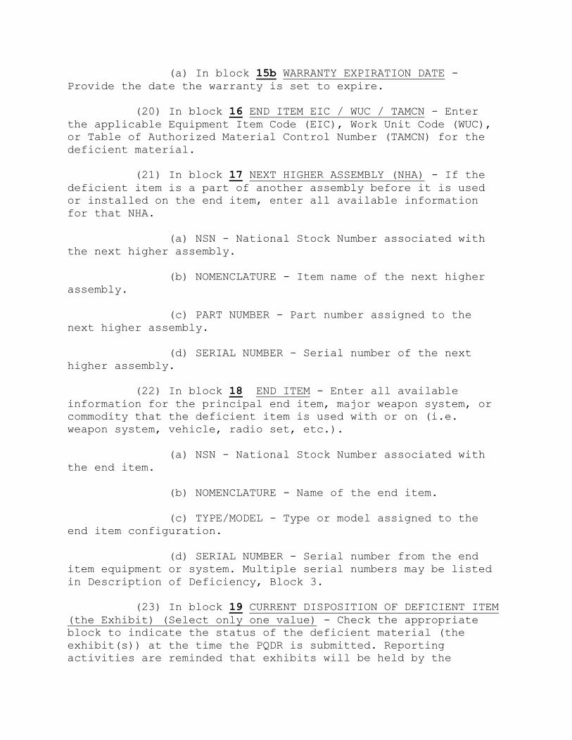
(a) In block 15b WARRANTY EXPIRATION DATE -
Provide the date the warranty is set to expire.
(20) In block 16 END ITEM EIC / WUC / TAMCN - Enter
the applicable Equipment Item Code (EIC), Work Unit Code (WUC),
or Table of Authorized Material Control Number (TAMCN) for the
deficient material.
(21) In block 17 NEXT HIGHER ASSEMBLY (NHA) - If the
deficient item is a part of another assembly before it is used
or installed on the end item, enter all available information
for that NHA.
(a) NSN - National Stock Number associated with
the next higher assembly.
(b) NOMENCLATURE - Item name of the next higher
assembly.
(c) PART NUMBER - Part number assigned to the
next higher assembly.
(d) SERIAL NUMBER - Serial number of the next
higher assembly.
(22) In block 18 END ITEM - Enter all available
information for the principal end item, major weapon system, or
commodity that the deficient item is used with or on (i.e.
weapon system, vehicle, radio set, etc.).
(a) NSN - National Stock Number associated with
the end item.
(b) NOMENCLATURE - Name of the end item.
(c) TYPE/MODEL - Type or model assigned to the
end item configuration.
(d) SERIAL NUMBER - Serial number from the end
item equipment or system. Multiple serial numbers may be listed
in Description of Deficiency, Block 3.
(23) In block 19 CURRENT DISPOSITION OF DEFICIENT ITEM
(the Exhibit) (Select only one value) - Check the appropriate
block to indicate the status of the deficient material (the
exhibit(s)) at the time the PQDR is submitted. Reporting
activities are reminded that exhibits will be held by the

Originating Point until disposition instructions are received
from an appropriate Screening or Action Point. If shipping or
disposition instructions have not been received by 30 days, a
follow-up must be initiated with the appropriate Screening or
Action Point. Any packaging, packing and shipping containers are
to be held along with the exhibits to facilitate investigation.
When disposition is other than the listed items, check "OTHER"
and identify the nature of the disposition in the Description of
Deficiency, Block 3.
(24) In block 20 LOCATION OF DEFICIENT MATERIAL (e.g.
Base, Camp, Station, Supply Activity) - Enter the name and
location or supply activity that is currently holding the
exhibit/deficient material.
(25) In block 21 ACTION REQUESTED (Select only one
value) - Check the appropriate block to indicate the action you,
the Originator, have already taken or are requesting. If none of
the items indicate the actions taken or requested, check "OTHER"
and identify the nature of the action taken or requested in the
Description of Deficiency, Block 3.
(26) PQDR PROCESS AND ACTIONS OUTLINE:
User/Originator - Prepare PQDR
- Determine the level of severity
-- Compare with severity categories
- Forward report to the originating
point
Originating Point - Check for validity, completeness,
and accuracy of report
- Validate the level of severity
-- Assign report control number
-- Compare with severity categories
- Forward the report to the screening
point
Screening Point - Certify validity,
completeness, and
accuracy of report
- Certify level of severity category
- Acknowledge receipt to sender
-- Apply timeframe criteria
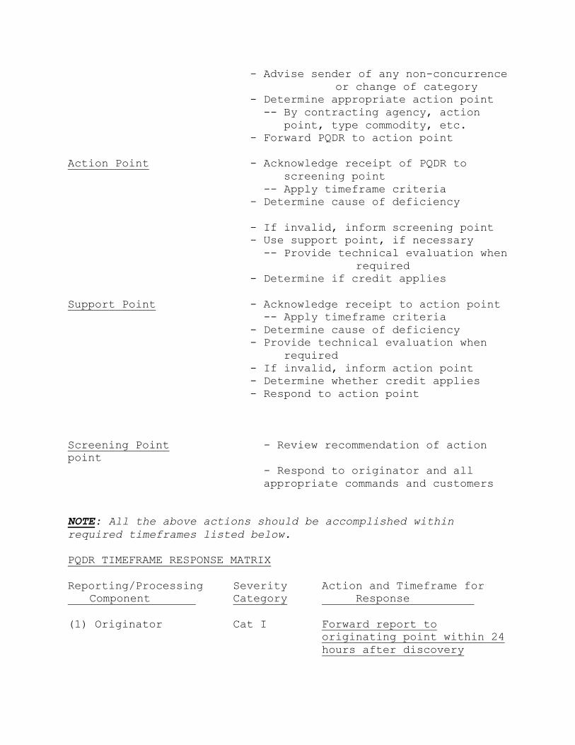
- Advise sender of any non-concurrence
or change of category
- Determine appropriate action point
-- By contracting agency, action
point, type commodity, etc.
- Forward PQDR to action point
Action Point - Acknowledge receipt of PQDR to
screening point
-- Apply timeframe criteria
- Determine cause of deficiency
- If invalid, inform screening point
- Use support point, if necessary
-- Provide technical evaluation when
required
- Determine if credit applies
Support Point - Acknowledge receipt to action point
-- Apply timeframe criteria
- Determine cause of deficiency
- Provide technical evaluation when
required
- If invalid, inform action point
- Determine whether credit applies
- Respond to action point
Screening Point - Review recommendation of action
point
- Respond to originator and all
appropriate commands and customers
NOTE: All the above actions should be accomplished within
required timeframes listed below.
PQDR TIMEFRAME RESPONSE MATRIX
Reporting/Processing Severity Action and Timeframe for
Component Category Response
(1) Originator Cat I Forward report to
originating point within 24
hours after discovery
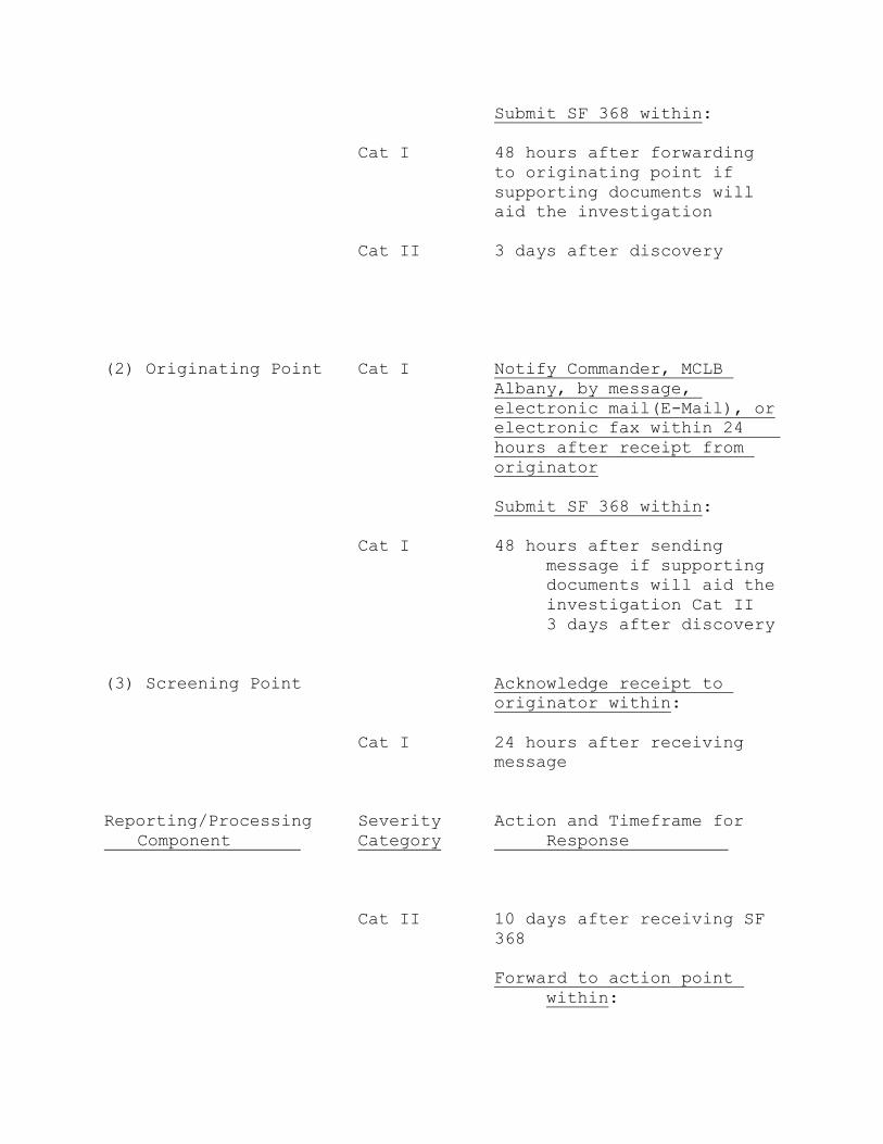
Submit SF 368 within:
Cat I 48 hours after forwarding
to originating point if
supporting documents will
aid the investigation
Cat II 3 days after discovery
(2) Originating Point Cat I Notify Commander, MCLB
Albany, by message,
electronic mail(E-Mail), or
electronic fax within 24
hours after receipt from
originator
Submit SF 368 within:
Cat I 48 hours after sending
message if supporting
documents will aid the
investigation Cat II
3 days after discovery
(3) Screening Point Acknowledge receipt to
originator within:
Cat I 24 hours after receiving
message
Reporting/Processing Severity Action and Timeframe for
Component Category Response
Cat II 10 days after receiving SF
368
Forward to action point
within:

Cat I 24 hours after receiving
message
Cat II 10 days after receiving SF
368
Final response to
originator within:
Cat I 3 days after receiving
response from action point
Cat II 3 days after receiving
response from action point
(4) Action Point Acknowledge receipt to
screening point within:
Cat I 24 hours after receiving
PQDR for action
Cat II 10 days after receiving SF
368
Suspend/screen stock
within:
Cat I 24 hours after receiving
PQDR or electronic fax
Cat II 20 days after receiving SF
368
Forward to support point
when assistance is required
within:
Cat I 24 hours after receiving
message, E-Mail, or
electronic fax
Cat II 10 days after receiving SF
368
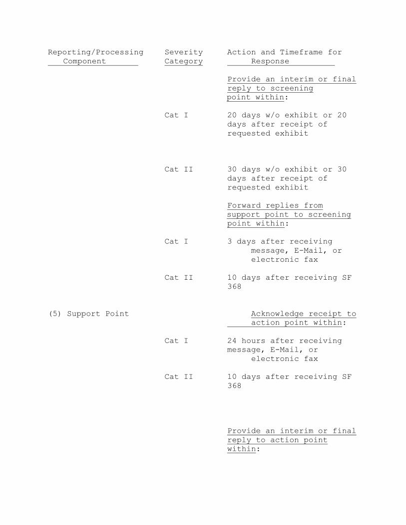
Reporting/Processing Severity Action and Timeframe for
Component Category Response
Provide an interim or final
reply to screening
point within:
Cat I 20 days w/o exhibit or 20
days after receipt of
requested exhibit
Cat II 30 days w/o exhibit or 30
days after receipt of
requested exhibit
Forward replies from
support point to screening
point within:
Cat I 3 days after receiving
message, E-Mail, or
electronic fax
Cat II 10 days after receiving SF
368
(5) Support Point Acknowledge receipt to
action point within:
Cat I 24 hours after receiving
message, E-Mail, or
electronic fax
Cat II 10 days after receiving SF
368
Provide an interim or final
reply to action point
within:
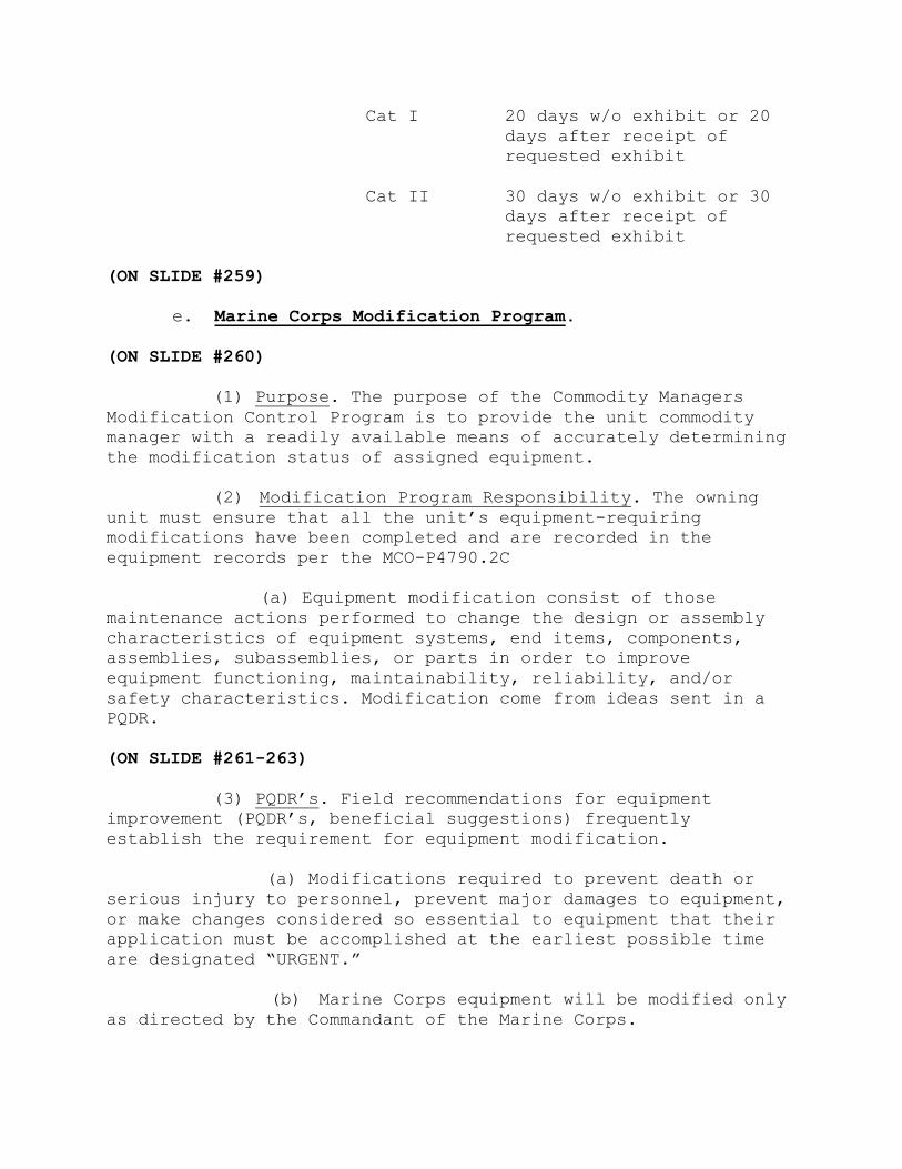
Cat I 20 days w/o exhibit or 20
days after receipt of
requested exhibit
Cat II 30 days w/o exhibit or 30
days after receipt of
requested exhibit
(ON SLIDE #259)
e. Marine Corps Modification Program.
(ON SLIDE #260)
(1) Purpose. The purpose of the Commodity Managers
Modification Control Program is to provide the unit commodity
manager with a readily available means of accurately determining
the modification status of assigned equipment.
(2) Modification Program Responsibility. The owning
unit must ensure that all the unit’s equipment-requiring
modifications have been completed and are recorded in the
equipment records per the MCO-P4790.2C
(a) Equipment modification consist of those
maintenance actions performed to change the design or assembly
characteristics of equipment systems, end items, components,
assemblies, subassemblies, or parts in order to improve
equipment functioning, maintainability, reliability, and/or
safety characteristics. Modification come from ideas sent in a
PQDR.
(ON SLIDE #261-263)
(3) PQDR’s. Field recommendations for equipment
improvement (PQDR’s, beneficial suggestions) frequently
establish the requirement for equipment modification.
(a) Modifications required to prevent death or
serious injury to personnel, prevent major damages to equipment,
or make changes considered so essential to equipment that their
application must be accomplished at the earliest possible time
are designated “URGENT.”
(b) Marine Corps equipment will be modified only
as directed by the Commandant of the Marine Corps.

(c) Equipment modification requirements will
include the detailed step-by-step procedures for accomplishment,
and are published as Modification Instructions (MI).
(d) They identify specific types and items of
equipment to be modified as well as the maintenance resources,
skills, and time necessary for their accomplishment.
(e) MI’s specify the EOM authorized to perform
the modification. Equipment to be modified is identified by
nomenclature, ID Number, NSNS, and the manufacturer’s serial
number for individual equipment, when appropriate.
(f) Unit commodity managers will maintain the
Modification Control based on information obtained from other
records and physical observation of the equipment.
(g) The SL-6-1 and SL-6-2 may be used to identify
“Consist Of” ID numbers for end items. “Part Of” is an item that
is a component or repair part to another item. “Consist Of”
refers to one item that consists of different components or
different repair parts having individual ID numbers.
(h) Enter the serial number for each T/E and
special allowance item with a modification instruction
published. (The quantity of equipment may require preparation of
multiple sheets for a given type of equipment.) In cases where a
serial number has not been assigned, a local serial number must
be assigned to the item per the UM-4400-124.
(i) Enter all MI’s listed in the SL-1-2 and TI-
5600 for the item’s ID number. Changes to the basic MI that are
administrative in nature, (i.e., part number/NSN change) will be
recorded under the basic MI, for example, MI-012345A-24/25A
w/ch1. When the change alters the configuration of the
modification or adds/deletes applicable serial numbers, control,
or manufacturers number a separate entry for that change is
required for verification purposes.
(4) Upon Initial Reciept
(a) Upon initial receipt of equipment items, they
will be inspected to determine if all required modifications
have been properly completed.

1 When the nature of the required
modification is such that the owning unit cannot determine if it
has been completed, the equipment will be evacuated to the IMA
for such determination.
2 When inspection is completed, initiate a
Service Request for missing modifications to be applied.
3 Commodity manager will then update the
required item instances per TM-4700-15/1C, GPN 4-12.
(b) Each Item Instance on T/E that has had an MI
issued will be accounted for in GCSS-MC.
(5) Preparation instructions. All modifications will
be pushed through install base by LOGCOM. All records of
modifications will be added as a child to the item instance.
(6) Category and Required Completion Date. Enter a “U”
for Urgent MI’s, “N” for Normal MI’s, and required completion
date.
(ON SLIDE #264)
(a) Urgent MI's will be identified in the SL-1-2
by the letters "URG" following the MI number. The required
completion date can be found in the "Time Compliance Period"
paragraph of the MI. If the urgent MI indicates upon receipt or
does not have a completion date, enter "N/A" for the required
completion date.
NOTE: “URGENT” modifications that require the equipment be
deadlined or its use sharply curtailed until modification is
applied. Under such conditions, acceptance scheduling normally
will not be feasible. Other “URGENT” modifications, though
requiring timely application, may lend themselves to acceptance
scheduling. In both instances, the urgency of the required
modification must be considered to establish its priority.
(b) MI’s not designated as urgent in the SL-1-2
fall into the “NORMAL” category. The required completion date of
“NORMAL” MI’s is 1 year from the date of the MI, unless the MI
indicates otherwise.
1 Equipment in level “A” Pack need not be
opened to perform “NORMAL” MI’s. The required modification kits
will be requisitioned, and placed into an Layette bin or other
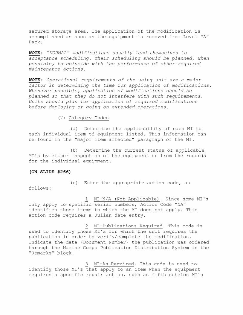
secured storage area. The application of the modification is
accomplished as soon as the equipment is removed from Level “A”
Pack.
NOTE: “NORMAL” modifications usually lend themselves to
acceptance scheduling. Their scheduling should be planned, when
possible, to coincide with the performance of other required
maintenance actions.
NOTE: Operational requirements of the using unit are a major
factor in determining the time for application of modifications.
Whenever possible, application of modifications should be
planned so that they do not interfere with such requirements.
Units should plan for application of required modifications
before deploying or going on extended operations.
(7) Category Codes
(a) Determine the applicability of each MI to
each individual item of equipment listed. This information can
be found in the "major item affected" paragraph of the MI.
(b) Determine the current status of applicable
MI's by either inspection of the equipment or from the records
for the individual equipment.
(ON SLIDE #266)
(c) Enter the appropriate action code, as
follows:
1 MI-N/A (Not Applicable). Since some MI's
only apply to specific serial numbers, Action Code “NA”
identifies those items to which the MI does not apply. This
action code requires a Julian date entry.
2 MI-Publications Required. This code is
used to identify those MI's for which the unit requires the
publication in order to verify/complete the modification.
Indicate the date (Document Number) the publication was ordered
through the Marine Corps Publication Distribution System in the
“Remarks” block.
3 MI-As Required. This code is used to
identify those MI’s that apply to an item when the equipment
requires a specific repair action, such as fifth echelon MI's

for rebuild, contact team application, or when a specific
component is repaired/replaced. This code would also apply to
items of equipment that would require the modification, however;
based on the unit’s mission and Table of Equipment (T/E), only a
percentage of the end items are modified. Enter an “AR” for
those item not currently modified.
NOTE: The action code, “AR”, should be used for end items that
may not require the modification to be applied (e.g., radio
mounts; not all unit’s vehicles would require these mounts, so
modification is optional yet required to be identified for that
particular end item). The “AR” entry allows the flexibility of
changing the modification record in the event the modification
is applied to that end item at a later date. AR action code
entries are made in pencil and do not require a Julian date.
4 MI-Completed. This code identifies
equipment modified while in custody (on the property records) of
the unit. This includes items modified for the unit by the
intermediate maintenance activity. This action code requires a
Julian date entry.
5 MI-Verified. This code identifies
equipment modification has been verified (normally used upon
initial receipt). This action code requires a Julian date entry.
(6) Marine Corps Publication Website.
http://www.logcom.usmc.mil/sp_logon/
INTERIM TRANSISTION: We’ve just covered the PQDR form SF-368 and
Modification program, are there any questions? If not we will
take a ten minute break then you will have two practical
applications .
________________________________________________________________
________________________________________________________________
________________________________________________________________
(BREAK – 10 Min)
INTERIM TRANSITION: Did anyone think of any questions during
the break? If not, let’s go into the practical applications.
________________________________________________________________
________________________________________________________________
________________________________________________________________
PRACTICAL APPLICATION. (30 MIN) Each student will accomplish the
assignment on their own. There is one instructor required Each
student will access and use GCSS-MC Online Training UPK and
perform the “Try it” and “know it” modes for the following
modules:
201.05.02.03 - Managing Modification Instruction (MI) Updates
STUDENT ROLE: Students will log on and perform prac app at their
own pace. When finished they should sit quietly until all the
other students are finished.
INSTRUCTOR ROLE: Instructor should click on Softlink icon in
order to view the student’s progress. This also allows the
instructor to ensure students aren’t viewing other websites and
staying on task.
1. Safety Brief: N/A
2. Supervision and Guidance: Instructor should also walk around
the room and answer questions as they come up.
3. Debrief: Allow students the opportunity to ask questions and
comment on the demonstration. Answer student questions and
provide feedback on student comments.
INTERIM TRANSITION: You have just completed your first prac-ap
covering Mods in the UPK, are there any questions? If not, you
will perform a Practical Application.
________________________________________________________________
________________________________________________________________
________________________________________________________________
INTRUCTOR NOTE
Introduce the following Practical Application.
PRACTICAL APPLICATION. (30 MIN) Each student will be given a
hand out at the beginning of this prac ap. Hand out will be kept
inside the filing cabinet located in the classroom. The purpose
of this prac ap is to enhance the knowledge of the Modification
program. Student to instructor ratio is 25:1. Students will work
questions 1-5 individually, for question 6, the first group of
students finished with questions 1-5 will take the Mods binder
to verify the modifications on the Buffalo. One group will go at
a time and will be grouped in no more than five students.
STUDENT ROLE: Students will utilize the handout in conjunction
with the Pubs website in order to perform this prac ap. Student
will answer first five questions in class room. Once complete
Students will receive Modification binder with all MI’s and
proceed to the Buffalo in the training area parking lot to
answer question 6.
INSTRUCTOR ROLE: Distribute student handout, explain to the
students they will answer first five questions in class room.
Once complete they will receive Modification binder with all
MI’s and proceed to the Buffalo in the training area parking lot
to answer question 6. Students will be grouped in no more than
five students.
1. Safety Brief: N/A
2. Supervision and Guidance: Instructor should also walk around
the room and answer questions as they come up.
3. Debrief: Allow students the opportunity to ask questions and
comment on the demonstration. Answer student questions and
provide feedback on student comments.
TRANSISTION: We’ve just covered the PQDR form SF-368 and
Modification program, are there any questions? If not, I have
several for you.Q1: what is the purpose of the PQDR? A1:
Provides information to activities responsible for development,
procurement, or management of equipment concerning deficiencies
in material, design, or procurement. 2. Q2: Urgent modifications
are for? A2: Prevent death or serious injury to personnel,
prevent major damages to equipment, or make changes considered
so essential to equipment that their application must be
accomplished at the earliest possible time. Q3:When is the
option MI- Verified utilized? A3: When modifications are checked
upon receipt of equipment. Take a ten minute break.
________________________________________________________________
________________________________________________________________
________________________________________________________________
(BREAK – 10 Min)
INTERIM TRANSITION: Did anyone think of any questions during the
break? If not, let’s talk about Demand Supported Items.
______________________________________________________________________
______________________________________________________________________
____________________________________________________
(ON SLIDE #)
8. Demand Supported Items (Formally PEB). (50 MIN)
a. Criteria Requirements for Demand Supported Items.
(1) Definition. Demand-supported stocks are those
quantities of expendable and nonexpendable items which are on
hand based on supported or limited stockage criteria and are
authorized to support mission requirements. Demand-supported
items typically but not exclusively, consist of class IX, repair
parts such as:
(a) Commonly used hardware items, such as nuts,
bolts and battery terminals.
(b) Items used during PM such as filters, belts,
hoses.
(c) High usage items that affect readiness of a unit
such as voltage regulators, weapons parts and
radio hand sets.
(2) Purpose. The primary purpose for maintaining demand
supported items is to place fast moving, low-cost items at the
same location as the customer who requires them. Stocking these
items at the maintenance commodity allows an expedited return of
critical assets to an operational status.
b. Requirements for Demand Supported Items.
(1) When it is determined that demand supported items
will enhance the maintenance effort, the unit commander will
publish a letter authorizing specific items to be included. The
letter will contain, as a minimum, the following information
concerning the items authorized for storage:
(a) Nomenclature.
(b) NSN/Part Number.
(c) Minimum/Maximum Quantity Authorized.
(e) Unit of Issue/Measure.

(d) Unit Price.
(e) Extended Price (Quantity Authorized Multiplied
by Unit Price).
(2) Commanders will review and approve (in writing)
items for demand supported items at least annually. Prior to
routing request to CO for approval all requests will be reviewed
by the appropriate supporting Supply Management Unit (SMU) for
endorsement (MSC G-4 if not supported by SMU). SMU will not
dictate stock levels but will recommend based on current stock
and demand history. The SMU input will be an endorsement to the
annual formal request. Once approved the Supply Officer and MMO
will review the demand-supported stockage listing quarterly to
ensure the expenditure of funds is consistent with the needs of
the unit and maintained at appropriate levels of range and
depth. Commanders may approve changes to this listing based on
the quarterly reviews without SMU endorsement however the
endorsement is still required annually. If an enclosure is used
to list the demand supported items, the commander must initial
each page of the enclosure.
(a) Demand supported item criteria are as follows:
1 Annual approval by the CO in writting.
2 The usage history (issues) is sufficient to
justify maintaining available stocks on hand. Usage history is
as follows:
a For those items applied/consumed as
a full U/I, the usage criteria is six U/I's applied/consumed in
12 months based on maintenance usage.
b For those items applied/consumed as
less than a full U/I (e.g. roll, hundred, or box, etc.) the
usage criteria is one U/I applied/consumed in 12 months.
c Capture usage data by debriefing the
demand supported items via parts debrief utilizing the WRS code
of PB.
3 Stocks are consistent with a units funding
and embarkation capability, and the units maintenance
requirements.
(3) Demand-supported items stocked using the above
criteria must be reviewed and if required adjusted quarterly.
Once an item is eligible stock levels will consist of the
following:
(a) Operating Level (OL). The OL determines the
frequency at which supplies are ordered. Typically, the OL is
the 30-day usage requirement for each individual item.
(b) Safety Level (SL). The quantity of material to
be on hand to permit continued operation in the event of a minor
interruption of normal replenishment or a fluctuation in demand.
Typically the SL is set at 30 days.
(c) Customer Wait Time (CWT). CWT is the total
elapsed time between issuance of a customer order and
satisfaction of the order. CWT is the portion of the total OL
quantity which covers the CWT replenishment requisition.
(d) Min/Max. Established to support the requirements
for maintaining Demand-supported items. Min represents the
minimum on hand to sustain operations, the max is the maximum
quantity authorized by the CO to be maintained.
(4) Broken Units of Issue of common hardware (i.e.,
bolts, nuts, screws, washers, etc.) that has a unit of issue
other than each i.e. hundred, box, dozen etc. which are ordered
against a corrective SR that do not meet demand-supported
stockage criteria, do not require any further control or
accounting once the U/I is applied to the equipment. The left
over portion will be displayed in a parts bin, in plain view of
the shop’s maintenance personnel and used until exhausted.
Strict control and accountability is not required , but
maintenance supervisors must ensure maintainers know how to use
the on hand supply before ordering more.
(a) BUI’s not considered common hardware or costing
more than $5 per U/I will be added to the authorized demand-
supported stockage listing. They must be identified on the list
as BUI’s and reflect the date that they were added to the list.
They may be retained as demand- supported stockage items until
exhausted.
e. GCSS-MC Min/Max Planning Report.

(1) The Min/Max Planning Report is used to maintain
inventory levels for all of your Demand-supported Items by
specifying minimum and maximum inventory levels.
(2) When the inventory level for an item (on-hand
quantities plus quantities on order) drops below the minimum
GCSS-MC Inventory suggests a new purchase requisition, internal
requisition, move order, or job to bring the balance back up to
the maximum inventory level.
f. The Columns of the Report are as Follows:
(1) Item. By National Item Identification Number
(NIIN).
(2) Category Quantity. Defaults to zero.
(3) Minimum Quantity. Minimum quantity per the Demand-
supported Items authorization letter
(4) Maximum Quantity. Maximum quantity per the Demand-
supported Items authorization letter
(5) On Hand. Quantity you have in your Demand-supported
Items.
(6) Supply Quantity. Ordered by Supply pending
replenishment
(7) Demand Quantity. Quantity being requested by
Maintenance through a Service Request
(8) Available Quantity. The on hand plus the supply
minus the demand quantities (AV = OH + SUP – DEM)
g. Extract a Min/Max Planning Report.
(1) Parameters Of The Min/Max PLANNING Report
(a) The “Review of Parameters on a Min/Max Planning
Report” document explains the details of the report parameters
and the fields of value required to run the report such as
organization, from and to and sort by.
(b) Maintenance management and maintenance
personnel will manage two major parameters for the min/max
planning report.
(2) Organization. Select using unit organization.
(a) Restock. This field is indicated by a "No" or
"Yes" value. IMPORTANT! If you choose “Yes” in the following
field, you will generate an automatic order for ALL parts which
are below the Minimum Stocking Level.
h. Generate a Move Order. After reviewing the Min-max
planning report and determining the quantities should be
executed, set the Restock parameter to "Yes" to generate the
Move Order. Quantities generated for the Move Order are the
quantities displayed in the "Reorder Quantity" column of the
Min-max planning report.
i. Action Required for a Broken Unit of Issue/Measure.
The Maintenance Management Chief/Maintenance Chief will inform
Supply when there is a Broken Unit of Issue/Measure has been
received and identified. Supply will then change the unit of
issue of item(s) to “EA” (each), and place the remaining
quantities in the Demand-supported Items.
j. Stock locator.
(1) Purpose. The purpose of the stock locator is
ensure all Demand-supported Items have properly been assigned an
area, space, or compartment for temporary storage until
consumed; and to allow personnel to quickly and accurately
locate parts as needed.
(2) Locator. A locator is part of a nine digit
numbering system used for locating requisitioned items such as
repair parts. Each requisitioned item will be assigned a stock
locator number that corresponds to it’s physical location within
an area. This area could be part of a maintenance shop’s
Layettes or Demand-supported Items. To set up stock locator
numbers you must coordinated with Unit Supply and IAW MCO
P4450.7_ (Please read the reference for a complete explanation)
The stock locator number will then be loaded electronically into
Global Combat Support System – Marine Corps (GCSS-MC) to
electronically track the physical location of requisitioned
items. Presently there are two stock location numbering systems
used within the Marine Corps Deployable and Non-Deployable.
INSTRUCTOR NOTE
Refer students to MCO P4450.7_ pg 2-7 and Appendixes B & C.
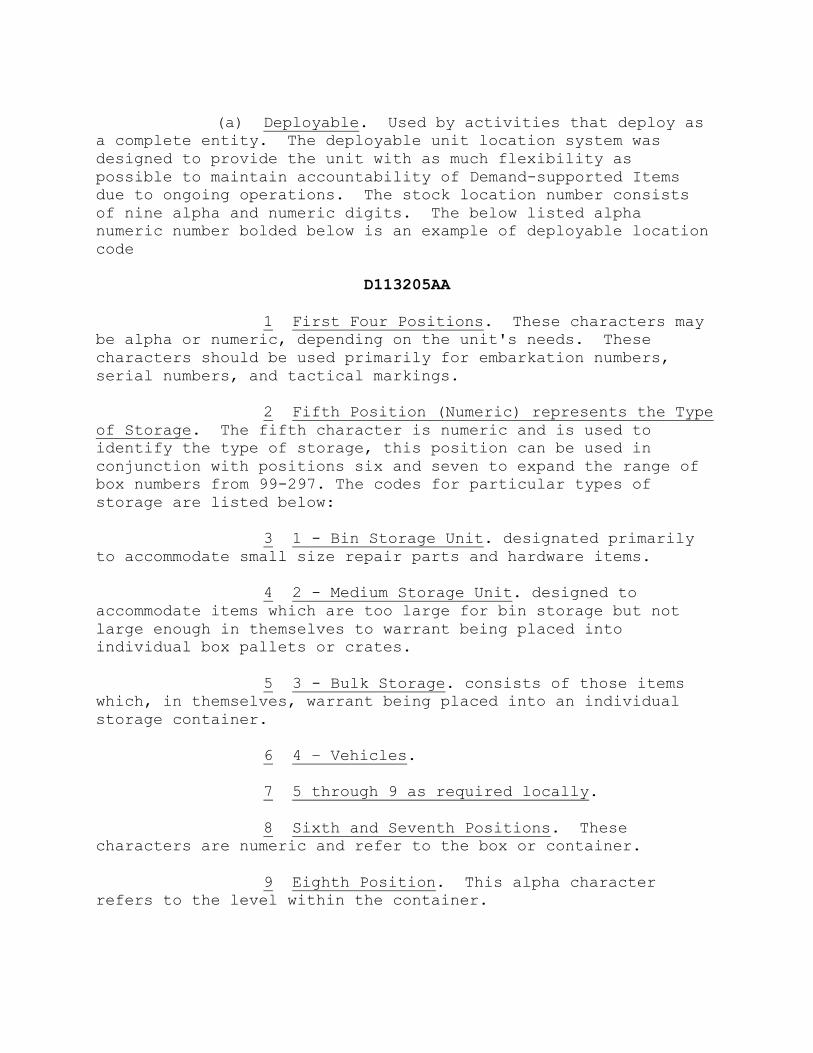
(a) Deployable. Used by activities that deploy as
a complete entity. The deployable unit location system was
designed to provide the unit with as much flexibility as
possible to maintain accountability of Demand-supported Items
due to ongoing operations. The stock location number consists
of nine alpha and numeric digits. The below listed alpha
numeric number bolded below is an example of deployable location
code
D113205AA
1 First Four Positions. These characters may
be alpha or numeric, depending on the unit's needs. These
characters should be used primarily for embarkation numbers,
serial numbers, and tactical markings.
2 Fifth Position (Numeric) represents the Type
of Storage. The fifth character is numeric and is used to
identify the type of storage, this position can be used in
conjunction with positions six and seven to expand the range of
box numbers from 99-297. The codes for particular types of
storage are listed below:
3 1 - Bin Storage Unit. designated primarily
to accommodate small size repair parts and hardware items.
4 2 - Medium Storage Unit. designed to
accommodate items which are too large for bin storage but not
large enough in themselves to warrant being placed into
individual box pallets or crates.
5 3 - Bulk Storage. consists of those items
which, in themselves, warrant being placed into an individual
storage container.
6 4 – Vehicles.
7 5 through 9 as required locally.
8 Sixth and Seventh Positions. These
characters are numeric and refer to the box or container.
9 Eighth Position. This alpha character
refers to the level within the container.
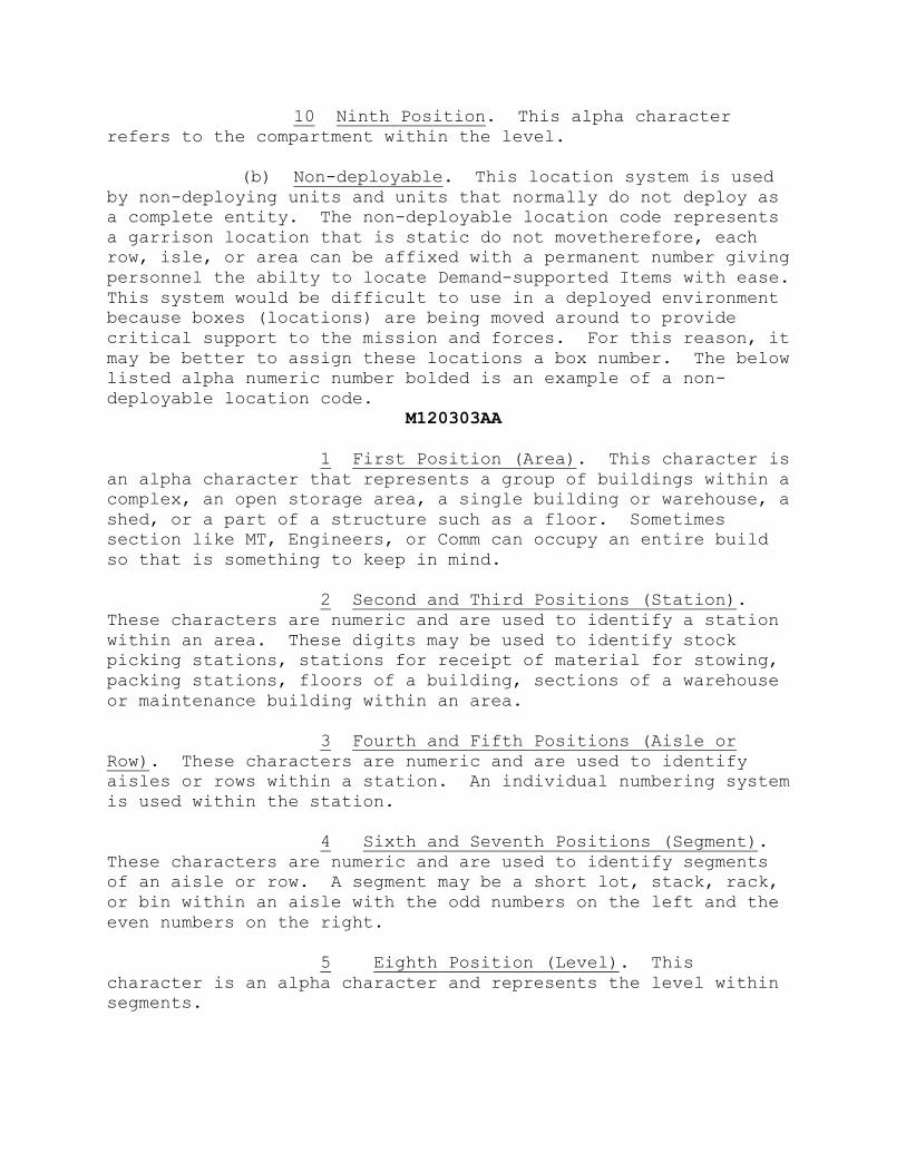
10 Ninth Position. This alpha character
refers to the compartment within the level.
(b) Non-deployable. This location system is used
by non-deploying units and units that normally do not deploy as
a complete entity. The non-deployable location code represents
a garrison location that is static do not movetherefore, each
row, isle, or area can be affixed with a permanent number giving
personnel the abilty to locate Demand-supported Items with ease.
This system would be difficult to use in a deployed environment
because boxes (locations) are being moved around to provide
critical support to the mission and forces. For this reason, it
may be better to assign these locations a box number. The below
listed alpha numeric number bolded is an example of a non-
deployable location code.
M120303AA
1 First Position (Area). This character is
an alpha character that represents a group of buildings within a
complex, an open storage area, a single building or warehouse, a
shed, or a part of a structure such as a floor. Sometimes
section like MT, Engineers, or Comm can occupy an entire build
so that is something to keep in mind.
2 Second and Third Positions (Station).
These characters are numeric and are used to identify a station
within an area. These digits may be used to identify stock
picking stations, stations for receipt of material for stowing,
packing stations, floors of a building, sections of a warehouse
or maintenance building within an area.
3 Fourth and Fifth Positions (Aisle or
Row). These characters are numeric and are used to identify
aisles or rows within a station. An individual numbering system
is used within the station.
4 Sixth and Seventh Positions (Segment).
These characters are numeric and are used to identify segments
of an aisle or row. A segment may be a short lot, stack, rack,
or bin within an aisle with the odd numbers on the left and the
even numbers on the right.
5 Eighth Position (Level). This
character is an alpha character and represents the level within
segments.
6 Ninth Position (Compartment). This is
an alpha character and identifies a subdivision of the level
within the segment, such as a drawer or compartment or bin.
k. Receipting Process in GCSS-MC.
(1) Per GPN 1-11 paragraphs 4.B.4.H & 4.B.5, 4.B.5.A
covers Confirmation of Reciept (COR)
(2) Per GPN 3-11 paragraph 8.B which outlines Layettes
Subinventory /Locator Management.
“Unit Supply will receipt for requisitioned items and place them
into the maintenance commodity stage subinventory. Once the
items are signed for and physically moved from the unit supply
issue point to the commodity section, it is the RESPONSIBILITY
of the MAINTENANCE COMMODITY SECTION to subinventory transfer
the item from the stage subinventory to the appropriate layette
subinventory/locator. At a minimum, every two weeks, these
subinventories will be reconciled aginst the service request to
ensure strict accountability of parts”.
l. Layette Sub Inventory/Locator Management. Unit supply
will receipt for requisitioned items and place them into the
maintenance commodities stage sub-inventory. Once the items are
signed for and physically moved from the units supply issue
point to the commodity section, it is the responsibility of the
maintenance commodity section to sub-inventory transfer the
items from the stage sub inventory to the appropriate layette
sub inventory/locator. The GCSS-MC sub-inventory/locator
numbering system will be in accordance with para 2005.3 (for
non-deployable) and 2005.4 (for deployable locators) of MCO
4450-7E. At a minimum, every two weeks, these sub-inventory
layettes will be reconciled against the service request to
ensure strict accountability of parts.
INTERIM TRANSISTION: We’ve just covered Demand Supported Items,
are there any questions? If not we will take a ten minute break
then you will have a practical application.
________________________________________________________________
________________________________________________________________
________________________________________________________________
(BREAK – 10 Min)
INTERIM TRANSITION: Did anyone think of any questions during the
break? If not, let’s go into the practical application.

______________________________________________________________________
______________________________________________________________________
____________________________________________________
INTRUCTOR NOTE
Introduce the following Practical Application.
PRACTICAL APPLICATION. (2 HRS) Each student will accomplish the
assignment on their own. There is one instructor required Each
student will access and use GCSS-MC Online Training UPK and
perform the “Try it” and “Know it” modes for the following
modules:
Inv 101.07.05.02.01-101.07.05.02.06
Plnr 101.02.02.01-101.02.02.07
Plnr 101.02.03.01-101.02.03.05
STUDENT ROLE: Students will log on and perform prac app at their
own pace. When finished they should sit quietly until all the
other students are finished.
INSTRUCTOR ROLE: Instructor should click on Softlink icon in
order to view the student’s progress. This also allows the
instructor to ensure students aren’t viewing other websites and
staying on task.
1. Safety Brief: N/A
2. Supervision and Guidance: Instructor should also walk around
the room and answer questions as they come up.
3. Debrief: Allow students the opportunity to ask questions and
comment on the demonstration. Answer student questions and
provide feedback on student comments.
TRANSISITION: Are there any questions concerning Demand-
supported Items or the practical application? If not, I have
several for you. Q1: What is the purpose of Demand-supported
Items? A2: Provides maintenance with ready access to a source of
common, low-cost, high-usage hardware items. Q2: At a minimum,
the letter authorizing maintenance to maintain Demand-supported
Items will have? A2: 1.Nomenclature 2. NSN/Part Number 3.
Minimum/Maximum Quantity Authorized 4. Unit of Issue/Measure 4.
Unit Price 5. Extended Price (Quantity Authorized Multiplied by
Unit Price). Q3: How often does the Demand-supported Items need
to be reviewed? A3: Quarterly by MMO/Supply Officer, Annualy by
CO. Q4:What is to be done with broken unit of issues? A5: The
leftover portion will still be accounted for in the Demand-
supported Items, however it will not be given a min-max. At this
time,let’s take a ten minute break.
________________________________________________________________
________________________________________________________________
________________________________________________________________
(BREAK – 10 Min)
TRANSISITION: Did anyone think of any questions during the
break? If not, let’s look at the Maintenance Production Report
(MPR).
________________________________________________________________
________________________________________________________________
________________________________________________________________
10. MAINTENANCE PRODUCTION REPORT (MPR). (50 MIN)
a. Purpose. This report provides maintenance managers at all
levels visibility of active SR’s in their shops.
b. Use. The information on this report provides the complete
history of an item in the maintenance cycle.
(1) Distribution of this report should be to the shop
section level and the unit MMO.
(2) Information for each open SR is presented in
numerical sequence.
(3) The first two lines of each SR present basic
identification data and current maintenance status of the
equipment.
(4) The third line for each SR is a listing of repair
parts requirements and the supply action to date on these
requirements. The MMO can quickly see the outstanding
requirements and their current status. This information can also
be used to verify that priorities of maintenance are in
agreement with repair parts requirements.

(5) Situations can also be spotted where maintenance
activities have added on parts, which may indicate poor initial
inspection. Repeat parts can be identified which may indicate
that parts previously received have been applied elsewhere, the
initial inspection was faulty, parts previously received were
faulty or damaged, or that the mechanic lost the part during
installation.
(6) Additionally, the misuse of operational statuses,
priorities, and NMCS/ANMCS indicators is recognizable. The MMO
can identify parts which have long lead-times based on current
status and take action to expedite.
(7) This report is a tool, which maintenance management
personnel can use to conduct the SASSY additional demand
reconciliation.
(8) For specific information on reconciliation, refer to
the current editions of MCO P4790.2_, UM 4400-124 and local
MMSOP.
(9) The MMO can identify the parts on requisition at a
different echelon of maintenance for an item of equipment.
(10) Finally, upon closeout, the MMO, maintenance
management personnel can see the labor and material resources
expended for a given SR.
c. Legend.
(1) First Line.
(a) SR. This column displays the Service Request
number.
(b) SR OWNER. This coulumn displays the units AAC,
RUC, and Section.
(c) TAMCN. This column displays the table of
authorized material control number of the equipment undergoing
maintenance. It consists of an Alpha character and followed by
four numbers (B0391). The Identification Number automatically
generates this entry from what is loaded in the ID Standards
File.

(d) Serial #. This column displays the
USMC/manufacturer's serial number of the equipment undergoing
maintenance.
(e) NIIN. This column displays the NIIN of the
equipment undergoing maintenance.
(f) MODEL. This column displays the Model type of the
equipment undergoing maintenance.
(h) ASR#. This column displays the IMA SR# in the
event the equipment undergoing maintenance and was evaced to
higher echelon. There are two ASR#’s to show up to 2 higher
evacs.
(2) Second Line.
(a) CONDITION. This column indicates the operational
status of the equipment.
(b) MI. MARES INDICATOR, this column displays whether
or not the equipment undergoing maintenance is Marine Corps
Automated Readiness Evaluation System (MARES) or NON-MARES
reportable.
(c) PRI. This column displays the priority of need
of the equipment having maintenance performed. Priorities can be
located in MCO 4400.16_.
(d) DCD. This column displays the deadline control
date. This date should reflect when the item of equipment
actually went deadlined.
(e) DDL. This column displays days deadlined. The
total number of days the equipment has been deadlined. This is
the sum of the current processing date minus the DCD for the
accumulated Operational Staus Deadlined.
(f) Job-Status. This column reflects the actions,
which have occurred on the equipment and the date each action
was initiated. Job Status Codes that initiate these codes are
located in the UM-4790-5, Ch. 24, pg. 24-5.
(g) DAYS IN STATUS. This column displays how many
days that the current JOB STATUS has been effect.
(h) Defect. This column displays the interpretation
of the defect code used in the input transaction. The first part
of the interpretation relates to the first character of the
defect code, and the second part of the interpretation relates
to the second and third characters of the defect code. The
defect interpretation shall be the major defect for item of
equipment undergoing maintenance. Defect Codes that initiate
these interpretations are located in the UM-4790-5, Ch. 24, pg.
24-3.
(i) DRIS. This column displays the date received in
shop. The equipment was received in the shop performing the
maintenance on this date.
(j) DIS. This column displays days in shop. The total
number of days the equipment has been in the maintenance shop.
This is the sum of the current processing date minus the DRIS.
(3) Third Line.
(a) Document #. This column displays the unit
document number used for repair parts requisitioned or the
applicable modification instruction number. When a secondary
repairable is issued over the counter to the customer by the
maintenance float or placed in a backorder status, the document
number of the maintenance float will be reflected.
(b) UOI. This column displays the unit of issue of
the item requested.
(c) Qty. This column displays the quantity of
material requisitioned.
(d) RECV. When an item has been received and the
receipt processed, the total amount received will be posted. If
the column has a 0 amount, it indicates the parts record is open
(still valid).
(e) Pri. This column displays the priority of the
requisition. The priority of the requisition may not exceed the
priority of the SR; however, parts may be requisitioned on a
lower priority. In other words, if the priority of the SR is 06
and parts are on order, there should be at least one priority 06
part on requisition. This does not preclude the requisitioning
of lower priority parts (13) on a priority 06 ERO.
(f) NSN. This column displays the national stock
number (NSN) or local stock number (LSN) of the part being
requisitioned.
(g) Part. This column displays the nomenclature of
the part requisitioned.
(h) STAT. This column displays the current status on
the requisition. The status code is a two-digit code, which
indicates the status of the requisition at the supply source.
When shipping status has been provided to the unit, the mode of
shipment code will be reflected. The mode of shipment code is a
one-digit code that identifies the means by which the item is
being shipped to the unit. These are generated by the source of
supply. Supply Status Codes can be found in the UM-4400-124, or
the Defense Logistics Agency Handbook.
(i) Date. This column displays the date the part went
into its current status.
(j) ESD. This column displays the Estimated Shipping
Date of the part being requistioned.
(k) DIC. This column displays the type of status
being provided. The type of status is identified by a document
identifier code (DIC). DICs in the “AE” series identify the
status as automatic supply status. DICs in the “AS” series
identify the status as automatic shipment status. Codes in the B
series will also appear. These are SASSY exception codes. An
exception is generated when a transaction processes against the
units loaded unit balance file (LUBF) and conditions were
present, which caused the exception to be created. When a
transaction fails to pass the master edit process in SASSY and
is rejected from processing, the letters REJ are entered.
DICs and exception codes are contained in UM-4400-124.
(l) LKH. This column identifies the last known holder
of the transaction. The routing identifier codes for last known
holders are contained in the current edition of UM 4400-71. When
the LKH is identified as FLT, it indicates that the maintenance
float is the supply source for the item. LKH can be found in the
Defense Logistics Agency Handbook.
(m) SHIP DATE. This column displays the date the part
being requistioned was shipped.
(n) TCN. Tracking Control number
d. Equipment Status Report.
(1) Description. This is a report listing each readiness-
reportable TAMCN and the quantity authorized, possessed, and
excess.
(2) Use. This report is a tool for the Commander, S-4,
and MMO to quickly review the Command's readiness status and to
identify problem areas.
(a) Legend. Data is portrayed on the report as
follows:
1 TAMCN. This column displays the Table of
Authorized Materiel Control Number (TAMCN) of the equipment
belonging to the unit.
2 ITEM DESCRIPTION. This column displays the noun
name of the equipment belonging to the unit.
3 MARES. This column displays whether or not the
equipment belonging to the unit is MARES REPORTABLE or not.
(b) Unit T/E RQMT. This column displays the reported
quantity of equipment for each TAMCN authorized the unit by
Table of Equipment (T/E) and/or special allowances.
(c) CMD Adjust. This column reflects the number of
equipment that the owning unit gained or dropped from their
account.
(d) Total RQMT. This column reflects the total
requirement for both Unit Requirement and Command ADJ.
(e) Excess Qty. This column displays the quantity of
equipment for each TAMCN that the unit has on hand over the
quantity authorized. If the quantity of equipment is equal to
or less than the quantity authorized, then this column will be
blank.
(f) Deficiency. This column reflects the total items
deficient.
(g) Deadlined Equip. This column displays the serial
number and ID number of the deadlined equipment.

(h) Original Date-DL. This column displays the date
in calendar year/Julian date format (97/002) on which the item
was deadlined.
(i) Supply Readiness. This column displays the
overall supply readiness.
(h) Readiness. This column displays the present
readiness posture.
(i) Maintenance Readiness. This column displays the
present Maintenance Readiness.
INTERIM TRANSISTION: We’ve just covered the MPR, are there any
questions? If not we will take a ten minute break then you will
have a two practical application.
________________________________________________________________
________________________________________________________________
________________________________________________________________
(BREAK – 10 Min)
INTERIM TRANSITION: Did anyone think of any questions during
the break? If not, let’s go into the demonstration.
________________________________________________________________
________________________________________________________________
________________________________________________________________
INTRUCTOR NOTE
Introduce the following Practical Application.
PRACTICAL APPLICATION. (1 hr) The S:I ratio is 25:1. The purpose
of this practical application is to create familiarize the
students on how to run both Equipment Status and Maintenance
Production Reports, The UPK player will be utilized for the
practical application. Students will perform prac app
individually. Students will have xx minutes for the practical
application.
PRACTICE: With minimal help of the instructor the students will
log onto GCSS online training and perform the following UPK
modules, in the “Try it” and “Know it” modes, at their own pace:
Maint 201.06.02.01 - Maint 201.06.02.02
When finished they should sit quietly until all the other
students are finished.
PROVIDE HELP: The primary instructor will identify required
procedures that the student must follow to complete the
practical application. Instructor should click on the Softlink
icon in order to view the student’s progress. Instructor should
patrol the classroom to ensure students are on the correct web
page and staying on task. Answer any questions or concerns that
arise IRT GCSS-MC and the UPK. The primary instructor will be
aided by the class lesson plan and the UPK at the podium.
1.Safety Brief: N/A
2.Supervision and Guidance: The primary instructor will move
about the classroom and provide additional guidance if needed.
3.Debrief: Primary instructor will have 15 minutes to review
the main ideas and allow students to comment on what they
experienced or observed. The instructor will provide overall
feedback and guidance on any misconceptions. Secondary
instructor will assist student in closing out the UPK player and
answering questions.
INTERIM TRANSITION: Do you have any questions on the practical
application? If not, you will perform the next Practical
Application.
________________________________________________________________
________________________________________________________________
________________________________________________________________
INTRUCTOR NOTE
Introduce the following Practical Application.
PRACTICAL APPLICATION. (1 hr) Each student will accomplish the
assignment on their own. Allow 30 minutes for completion and
review of this practical application exercise. There is one
instructor required. Distribute one copy of Corrective
Maintenance Practical Application “A” to each student. Read
each question to the students to ensure they understand the
requirements of the assignment. Handouts are located in the
classroom filing cabinet. Provide assistance as required to
each student. The purpose of this practical application is to
build the students knowledge of validating a MPR. This skill
will be evaluated by performance evaluation.
PRACTICE: Each student will analyze the same MPR and answer each
question. Students will work alone and raise their hand to gain
the attention of the instructor if they need assistance. When
finished they should sit quietly until all the other students
are finished.
PRACTICAL APPLICATION. Each student will analyze the same MPR
and answer each question. Students will work alone and raise
their hand to gain the attention of the instructor if they need
assistance.
PROVIDE HELP: The primary instructor will identify required
procedures that the student must follow to complete the
practical application. Instructor should click on the Softlink
icon in order to view the student’s progress. Instructor should
patrol the classroom to ensure students are on the correct web
page and staying on task. Answer any questions or concerns that
arise IRT GCSS-MC and the UPK. The primary instructor will be
aided by the class lesson plan and the UPK at the podium.
1.Safety Brief: N/A
2.Supervision and Guidance: The primary instructor will move
about the classroom and provide additional guidance if needed.
3.Debrief: Primary instructor will have 15 minutes to review
the main ideas and allow students to comment on what they
experienced or observed.
TRANSISITION: We’ve just covered the MPR, are there any
questions? If not, I have several for you. Q1: What is the
purpose of the MPR? A1: Provides maintenance managers at all
levels visibility of active SR’s in their shops. Q2: What does
the first two lines of the MPR represent? A2: Basic
identification data and current maintenance status of the
equipment. Q3: What does the third line of MPR represent? A3:
Listing of repair parts requirements and the supply action to
date on these requirements.
SUMMARY (10 min)
During the past week and a half we’ve covered the MPR, Purpose
of GCSS, NAVMC 10560, CM SR, Parts Requirement,SF 368, Mods,
Demand-supported Items, and Maintenace reports. I’m confident
that you’ll be able to return to your units and become a more
valuable asset with the knowledge you’ve gained from this class.
At this time the students with the Instructional Rating Forms go
ahead and fill those out, the rest of you take a ten minute
break.
________________________________________________________________
________________________________________________________________
________________________________________________________________
(BREAK – 10 Min)
REFERENCE:
Ground Equipment Record Procedures TM 4700-15/1_
Consumer Level Supply Policy Manual MCO P4400.150_
MIMMS field procedures Manual MCO P4790.2_.
GCCS-MC Procedural Notice 1-11
GPN 3-11
GPN 2-12
GPN 3-12
GPN 4-12
GPN 10-12
GPN 1-13
GPN 3-13


