
Petol Hydra-Tork
U118-115H
(Standard Base)
Operating Manual
Gearench PO Box 192
4450 South Highway 6 Clifton Texas 76634
Phone (254) 675-8651 Fax (254) 675-6100
copy 2005 by GEARENCH All rights reserved
Form U118115H revision 060905
2
Table of Contents
Petol U118-115H Hydra-Tork Description3 Warranty 4
Safe Practices and Procedures6 Responsibility 6 Replacement Parts 6 Safety 6 Safe Practices 7 Safety Sources and Publications 8 Responsibility of Distributors 8
Tong and Vise Chain Inspection 9 Overloading Shock Loads Side Loading 9 Environmental Conditions 9 Normal Life Expectancy 10 Lubrication 10 Periodic Inspection List for Petol Special Chain 11
Installation14 Location 14 Setup 14 Electrical Wiring 14 Startup 14
Operation 15 Controls 15 Torque-pressure conversion (118) 16 Torque-pressure conversion (115H) 17 Loading 19 Vise and Tong Adjustment 19 Breaking Out 19 Making Up 19
Parts List 21 Final Assembly 23 Console Assembly 25 Hydraulic Schematic 27 Control Panel 29 Main Electrical Panel 31 Cylinder Assembly (118) 33 Cylinder Assembly (115H) 33 Vee Saddle Assembly 34 Vise Assembly (118) 35 Vise Assembly (115H) 36 Tong Assembly (115H) 38 Petol Special Chain (118) 39 Petol Special Chain (118) 39 Petol Special Chain (115H) 39 Electrical Schematic 40
3
Petol U118-115H Hydra-Tork Description The U118-115H Petol Hydra-Tork unit was designed for making up and breaking out downhole tools The unit is equipped with two tongs and vises on one base and powered by one hydraulic console The 118 tong and vise are rated for operation on 4rdquo to 24rdquo diameters with a maximum working load of 90000 ft-lb The 115H tong and vise are rated for use on 2 to 8 diameters with a maximum working load of 14000 ft-lb The Petol Pulldown Visetong and Petol Tongvise are adjusted to the different ODs within their range by pulling the Petol Special Chain through the jaw and engaging a cam lock lever No addition or removal of chain sections is required The U118-115H also offers the following features
A shock mounted hydraulic console not attached to the base to provide maximum flexibility in the setup and location of the power unit for efficient use of shop space All controls are 24 volts AC NEMA type 13 The tong cylinder and vise base are mounted on tracks for switching from make up to break out One adjustable vee-saddle mounted on the hydra-tork base for added support This vee-saddle is also mounted on tracks for easy adjustment Operating voltages are 208240460 volts 3 phase 10 horsepower 277380 volts 3 phase 10 horsepower is available upon request
4
Warranty What Is Covered Gearench tools are expressly warranted to you the purchaser to be free of defects in material and workmanship How Long Coverage Lasts This express warranty lasts for the lifetime of the GEARENCH tool Warranty coverage ends when the tool becomes unusable for reasons other than defects in workmanship or material How Can You Get Warranty Service To obtain the benefit of this warranty contact a GEARENCH sales representative in Clifton Texas
GEARENCH 4450 South Highway 6 PO Box 192 Clifton TX 76634 What Will We Do To Correct Problems Warranted products will be repaired or replaced at GEARENCHrsquos option and returned at no charge to you the original purchaser or if after three attempts at repair or replacement during the warranty period the product defect in material or workmanship persists you can elect to receive a full refund of your original purchase price for the product What Is Not Covered Defects failures or conditions that are due to normal wear and tear abuse or misuse are not covered by this limited warranty In addition this limited warranty is in lieu of all other warranties express or implied verbal or written To the maximum extent allowed by law GEARENCH disclaims all implied warranties including implied warranties of merchantability andor fitness for a particular purpose GEARENCH also specifically denies any liability for any incidental damages andor consequential damages including but not limited to property damage to property other than the product itself loss of sales profits down time costs or any other damages measurable in money whether or not included in the foregoing enumeration Please be advised that some states do not allow the exclusion or limitation of incidental or consequential damages so this limitation or exclusion may not apply to you This warranty gives you specific rights and you may also have other rights which vary from state to state province to province or country to country Are Personal Injuries Covered In the event you someone working for you or any other person sustain a personal injury as a result of using the GEARENCH tool GEARENCH limits its potential liability for such a claim or injury to the fullest extent allowed by law and disclaims and denies any liability for such personal injury Please be advised that some states do not allow the exclusion or limitation of liability for personal injuries so the above limitation or exclusion may not apply to you or the individual claiming injury No Other Express Warranty Applies This GEARENCH LIMITED WARRANTY is the sole and exclusive warranty express or implied for GEARENCH products No employee agent dealer or other person is authorized to alter modify expand or reduce the terms of this warranty or to make any other warranty on behalf of GEARENCH Law Applicable All matters related to the sale andor use of the GEARENCH tool that is the subject of this limited warranty along with the construction and enforcement of the terms of this limited warranty itself shall be subject to the substantive and procedural laws of the state of Texas not the conflicts of laws provisions of Texas but rather the laws of Texas themselves
5
Forum Selection Clause Any dispute arising out of the sale andor use of the GEARENCH tool that is the subject of this limited warranty shall be presented in the form of a claim or lawsuit to the offices of GEARENCH in Clifton Bosque County Texas No claim or suit may be brought against GEARENCH arising out of the sale andor use of the tool or arising out of the terms of this warranty except in such forum Purchase andor use of the GEARENCH tool makes you subject to the benefits and limitations of this limited warranty Accordingly any writ judgment or other enforcement obtained from a jurisdiction county parish state or federal court or other country other that from the forum identified above shall be void and unenforceable against GEARENCH Arbitration Clause In the event of dispute or claim arises out of the sale andor use of the GEARENCH tool that is the subject of this limited warranty or arises out of the interpretation or enforcement of the terms and conditions of this limited warranty such dispute shall be submitted to binding arbitration pursuant to the rules of the American Arbitration Association If required to accomplish the purpose of this Arbitration clause the purchaser hereby expressly waives any right to demand trial by jury Complete Agreement This express limited warranty contains the entire agreement regarding express or implied warranties related to the GEARENCH tool that is the subject of it No writing or language contained in the purchase order or any other document of the purchaser or invoice of GEARENCH or any intermediate seller shall be construed as modifying in any way the rights and liabilities contained in this limited warranty Gearench expressly disclaims any obligations expressed in any customer purchase order or document that are contrary to the terms and limitations of this warranty Severability If any term or limitation contained in this limited warranty is deemed unenforceable by law then the term shall be severed from the remaining portions of the limited warranty which shall remain enforceable All communications to GEARENCH regarding the use of the tool and any aspect of the sale of the tool of this limited warranty should be addressed to GEARENCH
GEARENCH 4450 South Highway 6 PO Box 192 Clifton TX 76634
6
Safe Practices and Procedures
Responsibility It is the responsibility of the employer to train the employee in the proper selection and usage of tools chains etc and to ensure that they are selected and used in that manner In many instances injury results because it is assumed that anybody knows how to use common hand tools Observations and the record show that this is not the case A part of every job instruction program should therefore be detailed training in the proper use of hand tools (and of all other special tools and equipment needed to accomplish the job) - (Source National Safety Council) Employers are responsible for the safe condition of tools and equipment used by employees including tools and equipment which may be furnished by employees - (Source OSHA 1910242A)
Replacement Parts Use only PETOL amp TITAN replacement parts - no other parts are of comparable strength quality and interchangeability
Safety While we pride ourselves on the quality and dependability we build into GEARENCH tools and products we caution users that it is only prudent to know and follow the simple rules of safety when using our products or anyone elses Always follow safe practices and procedures in accordance with the recommendations of OSHA The National Safety Council (NSC) The Hand Tools Institute (HTI) The National Association of Chain Manufacturers (NACM) The International Association of Drilling Contractors (IADC) Etc All applicable Governmental rules regulations or restrictions now in effect or which may be promulgated take precedence over the suggestions in this publication The information in this publication is designed to supplement standard safe practices and procedures not in lieu of or replacement thereof
7
Safe Practices (Source The National Safety Council) Failure to observe one or more of the following five safe practices accounts for most hand and powered tool accidents 1 ALWAYS WEAR SAFETY GOGGLES TO PROTECT EYES 2 SELECT THE RIGHT TOOL FOR THE JOB 3 KEEP TOOLS IN GOOD CONDITION 4 USE TOOLS CORRECTLY 5 KEEP TOOLS IN A SAFE PLACE Safety Goggles must always be worn by persons in any area where hand and powered tools are being used Never apply excess leverage to a wrench or tool by means of a Cheater Bar Never strike wrenches and tools with hammers or other objects All tools should be kept clean inspected on a regular basis and replaced when they show signs of wear Be especially careful not to place yourself in a position that could result in bodily injury in the event of a failure Brace yourself firmly and pull rather than push when wrenching (If necessary to push do so with the flat of the hand rather than gripping around the wrench) Never stand under or near loads being hoisted off the ground READ SAFE PRACTICES AND PROCEDURES MANUAL CATALOG INFORMATION AND PRODUCT LABELING PRIOR TO OPERATION Spinning and drill pipe chain cathead chain and the PETOL Connecting Link attachment are designed for the specific purpose for which the name indicates Chains and attachments that are to be used for any other purpose should be selected in accordance with the recommendations of ASTM NACM Riggers Handbook and the commercial chain manufacturers technical manuals
8
Safety Sources and Publications In the interest of Safety the following sources of safety information is furnished
The Hand Tools Institute (HTI)
25 North Broadway Tarrytown New York 10591 (914) 332-0040 wwwhtiorg The National Safety Council (NSC) 1121 Spring Lake Drive Itasca Illinois 60143-3201 (630) 285-1121 wwwnscorg International Safety Council 1121 Spring Lake Drive Itasca Illinois 60143-3201 (630) 285-1121
Responsibility of Distributors IT IS THE RESPONSIBILITY OF THE PURCHASERS OF GEARENCH PRODUCTS TO CONVEY THE INFORMATION IN THIS PUBLICATION AND ANY OTHER INFORMATION RELATING TO THE INDIVIDUAL PRODUCT THROUGH THE CHANNELS OF DISTRIBUTION DOWN TO AND INCLUDING THE INDIVIDUAL USING THE PRODUCT NOTE In view of the fact that the actual use determines whether safety requirements have been met the ultimate responsibility to comply rests with the end user
9
Tong and Vise Chain Inspection The service life of leaf chains can be altered by a variety of adverse operating conditions The following information discusses the most important of these conditions for consideration when operating or scheduling replacement of leaf chain systems
Overloading Shock Loads Side Loading Attempting to inch loads which are beyond the rated capacity of the tool Striking the tool with a hammer or other object while force is being exerted in an attempt to loosen a frozen joint Side pull on the chain Side pull can be caused by pulling or pushing on the tong in a direction that is not along a perpendicular plane unleveled mounting of the vise inadequate support of the part being broken out and improper seating of the part being broken out in the tong or vise Improper seating will occur when the OD of the part is not consistent within the width of the tong or vise jaw
Environmental Conditions Wrench chains operate in widely varying environments from wet outdoor conditions to mildly or highly corrosive industrial atmospheres They can also be exposed to abrasives such as sand or grit The possible effects include
Moisture - Corrosion and rust reduce chain strength by causing pitting and cracking Temperature - Very cold temperatures reduce chain strength by embrittlement Chemical Solutions or Vapors - Corrosive attack of the chain components grain structure andor the mechanical connections between the chain components (crevice corrosion) may occur Cracking often is microscopic Propagation to complete failure can be eventual or sudden Abrasives - Accelerated wearing and scoring of the articulating chain members (pins and plates) may occur with a corresponding reduction in chain strength Due to inaccessibility of the bearing surfaces (pin surfaces and plate apertures) wear and scoring are not readily noticeable
10
These conditions when coupled with normal chain wear and inherent residual stress (normally in the chain as constructed) can result in environmentally assisted failure It is impossible to predict chain life under complex conditions as the degree of hostility and its effects are dependent on many variables such as temperature time of exposure concentration of corrosive atmosphere or medium degree of abrasive wear etc Establishing the degree and frequency of unpredictable dynamic loading is also difficult
Normal Life Expectancy A leaf chains normal life expectancy can be expressed as a maximum percent of elongation This is generally between 2 and 3 of pitch As the chain flexes back and forth the bearing joints (pins and inside link plates) gradually wear from articulation As with all steel bearing surfaces the precision hardened steel joints of leaf chain require a constant film of oil between mating parts to prevent wear and to resist corrosion
Lubrication One of the most important but often-overlooked factors is adequate lubrication In addition to reducing internal friction maintaining a film of oil on all chain surfaces will inhibit rusting and corrosion This is important as corrosion of highly stressed hardened steel chain components can cause a major reduction in the load capacity of leaf chain and result in link plate cracking Protection from corrosion is important in storage as well as in service The factory lubricant applied to PETOL CHAIN is a Fingerprint Neutralizing Water-Displacing Corrosion Preventative This is an excellent rust and corrosion inhibitor for chains in storage When installing these chains new do not attempt to steam clean or degrease this lubricant A grade of SAE 30 or 40 weight nondetergent motor oil should be used as supplemental lubricant and a film of this oil should be maintained on all surfaces and internal bearing joints Also do not attempt to paint new chains Though painting may help inhibit corrosion it will seal off critical clearances and restricts oil from reaching the pin surfaces where it is needed for good joint lubrication When operating in dusty environments lubricated chains will accumulate a paste-like buildup of grime At periodic intervals this buildup should be removed by cleaning and the chain should be immediately relubricated Do not use caustic or acid type cleaners use a stiff brush and a certified safe petroleum base solvent
11
Periodic Inspection List for Petol Special Chain 1 PRIOR TO EACH USE LEAF CHAIN AND TOOLS SHOULD BE INSPECTED FOR SERVICEABILITY AND LUBRICATION 2 USE ONLY PETOL AND TITAN REPLACEMENT PARTS - NO OTHER
PARTS ARE OF COMPARABLE STRENGTH QUALITY AND INTERCHANGEABILITY
12
13
Safety Precautions 1 Always wear safety goggles to protect eyes 2 Select the right tool for the job 3 Keep tools in good condition 4 Use tools correctly 5 Keep tools in a safe place 6 Wear protective clothing gloves and safety shoes as appropriate 7 Use lengths of assembled chain Do not build lengths from individual components 8 Do not attempt to rework damaged chain by replacing only the components obviously faulty The entire chain may be compromised and should be discarded 9 Never electroplate assembled leaf chains or components Plating will result in failure from hydrogen embrittlement 10 Do not weld any chain or component Welding spatter should never be allowed to come into contact with chain or components 11 Leaf chains are manufactured exclusively from heat-treated steels and therefore must not be annealed If heating a chain with a cutting torch is absolutely necessary for removal the chain should not be reused 12 Inspect chains frequently and regularly for link plate cracking pin turning pin protrusion and corrosion 13 Use only PETOL amp TITAN replacement parts to ensure proper strength
14
Installation
Location The Petol Hydra-Tork Unit should be located in an area with adequate room to work the downhole tools The unit may be located indoors or outdoors upon solid level ground or a finished shop floor No special foundation is required
Setup Locate the hydraulic console in a convenient location and connect the hoses to the desired hydraulic cylinder
Electrical Wiring Connect electrical power to the console at the disconnect switch located in the access door of the main electrical panel at the top of the console A qualified electrician in accordance with all-applicable local codes and standards should make the electrical supply If the unit voltage must be changed to match the available supply voltage (eg after relocation) change the motor wiring at the motor in the lower section of the console change the primary leads on the control transformer in the main electrical panel and change the motor starter heater elements in the main electrical panel The spare parts list describes the heater elements needed for all voltages
Startup Verify that the oil level is within the operating limits as shown on the console sight glass Use Chevron AW-ISO46 or equal (20 gallons) Turn on the disconnect switch to power up the console Start the hydraulic pump and immediately press any one of the cylinder control buttons If the cylinder does not move and if no hydraulic pressure is indicated (1) immediately turn off the power (2) lock out the power supply to the console and (3) reverse any two of the power supply leads to obtain the correct pump rotation If the cylinder will only extend and not retract (1) turn off the power (2) lock out the power to the console and (3) reverse the hoses attaching the console to the cylinder Cycle the cylinder several times to clear the system of any entrapped air
15
Operation
Controls The operating controls are shown on Figures 1 and 2 on page 16 The disconnect switch is used to disconnect electrical power to the controls When this switch is on the motor may be started The POWER ON switch will start the hydraulic pump motor It contains an indicator light to show that the motor is on The POWER OFF switch is used to stop the motor The FILTER indicator light is used to monitor the hydraulic filter If this light is on while a cylinder is traveling the hydraulic filter element located in the lower portion of the console is dirty and must be replaced Use Schroeder MS-7 element or equal The TONG RATCHET and TONG ENGAGE buttons are used to control operation of the main cylinder Press the TONG ENGAGE button to apply torque Press the TONG RATCHET button to ratchet the tong back to the pull down position The pressure control knob is used to adjust the overall system pressure Turn the knob clockwise to increase pressure or counter-clockwise to decrease system pressure WARNING Never operate the tong with a pressure higher than required to
perform the make up or break out operation Operation at excessive pressure may damage the downhole tool andor injure personnel
WARNING Never operate the 115H tong or vise at a pressure greater than
1880 psi Excessive pressure will damage the tong and vise andor personnel The hydraulic pressure gauge is used to indicate the current system pressure in psi A conversion chart for equating the hydraulic pressure in psi to the torque output in ft-lb follows
16
Torque-pressure conversion (118)
TORQUE (ft-lb)
PRESSURE (psig)
TORQUE (ft-lb)
PRESSURE (psig)
0 0 16000 500 2000 65 17000 535 2500 80 18000 565 3000 95 19000 595 3500 110 20000 625 4000 125 21000 660 4500 140 22000 690 5000 155 23000 720 5500 175 24000 750 6000 190 25000 785 6500 205 30000 940 7000 220 35000 1095 7500 235 40000 1255 8000 250 45000 1410 8500 265 50000 1565 9000 280 55000 1725 9500 300 60000 1880 10000 315 65000 2035 11000 345 70000 2195 12000 375 75000 2350 13000 410 80000 2510 14000 440 85000 2665 15000 470 90000 2820
17
Torque-pressure conversion (115H)
TORQUE (ft-lb)
PRESSURE (psig)
TORQUE (ft-lb)
PRESSURE (psig)
0 0 3600 480 100 15 3800 510 200 30 4000 540 300 40 4500 600 400 55 5000 670 500 70 5500 740 600 80 6000 800 700 95 6500 870 800 110 7000 940 900 120 7500 1000
1000 135 8000 1070 1200 160 8500 1140 1400 190 9000 1210 1600 215 9500 1270 1800 240 10000 1340 2000 270 10500 1410 2200 295 11000 1470 2400 320 11500 1540 2600 350 12000 1610 2800 375 12500 1670 3000 400 13000 1740 3200 430 13500 1810 3400 455 14000 1880
18
19
Loading To load the downhole tool in the unit slide the vise left or right as needed Adjust the vee-saddle to support the tool when set into the vise Set the tool into the vise Position the tong for make up or break out as needed and set the tong onto the tool Adjust the vise and tong as described and latch the vise chain and tong chain CAUTION The vee-saddle must be used to support the tool while torquing
Vise and Tong Adjustment Release the cam lock on the tong and vise by depressing the cam lever and moving the pawl to the unlocked position (see figure 3 on page 18) Slide the chain through the tong or vise as needed to latch the chain screw nut into the jaw Move the pawl lever to the locked position and release the cam lever Check that the cam lever is latched Tighten the chain screw nut on the vise until hand tight Tighten the chain screw nut on the tong until it is hand tight and then loosen the chain screw nut on the tong 12 turn to provide proper ratcheting
Breaking Out Load the tool and adjust the tong and vise as described above Fully ratchet the tong Turn the pressure control knob fully counter-clockwise engaging the tong When the tong stops begin increasing the system pressure by turning the pressure control slowly clockwise Keep increasing the system pressure until the connection is broken loose or the working load of the tong is reached Do not exceed the rating of the tong Consult with GEARENCH as needed for help with the toughest break out jobs After the initial break out ratchet the tong fully and then alternately engage ratchet the tong until the connection is fully loosened
Making Up Load the tool and adjust the tong and vise as described above Make up the connection hand tight using TITAN chain tongs While pressing the TONG RATCHET button with the cylinder fully extended adjust the pressure control knob until the desired make up torque is displayed Engage the tong If the cylinder fully retracts without stalling cycle the tong (ratchet engage) Continue until the cylinder stalls
20
21
Parts List The following drawings diagrams and parts lists describe all parts which may be needed as replacement items Where appropriate standard industrial electrical and hydraulic components have been used Should a standard industrial item need replacing the item may be purchased locally To assist you in obtaining parts the OEM component manufacturer and model numbers are shown on the parts list Of course all replacement parts will be supplied by GEARENCH if you prefer to order from us All tong vise and chain components are manufactured only by GEARENCH DO NOT ATTEMPT TO SUBSTITUTE THESE COMPONENTS The unit will not work properly unless these components are matched to the specific application Consult our factory as your requirements change Any non-GEARENCH substitutions of these components void all warranties and subject the user to assumption of liabilities resulting from subsequent use
22
23
Final Assembly Item Qty Part Number Description MakeModel Notes
1 1 UHBASE-118-115H Base
2 1 UVS-114-1614-16 Vise slide (118)
3 1 TVA118 Vise (118) See pages 34-35
4 1 UVS-114-1614-09 Vise slide (115H)
5 1 TVA115H Vise (115H) See pages 34-35
6 1 UHCY-118-4 Cylinder (118) See pages 30-31
7 1 VTDA118 Tong (118) See pages 36-37
8 1 UHCY-115H-4 Cylinder (115H) See pages 30-31
9 1 VTDA115H Tong (115H) See pages 36-37
10 1 UHVSA-01 Vee saddle See pages 32-33
11 1 UHCN-118-000 Console See pages 22-29
12 2 UHCH-H07 Hose Assembly Gates 8C2AT-8MP-12FJX-240
Or equal
13 1 UHNP-0001 Nameplate
14 2 181-45-25T Chain (118) 4 ndash 12rdquo diameter see page 38
14 2 181-45-33T Chain (118) 4 ndash 18rdquo diameter see page 38
14 2 181-45-41T Chain (118) 4 ndash 24rdquo diameter See page 38
15 2 151-45-25T Chain (115H) 2 ndash 8rdquo diameter See page 38
24
25
Console Assembly Item Qty Part Number Description MakeModel Notes
1 1 UHCH-118-000 Hydraulic schematic See pages 24-25
2 1 UHCN-P1-000 Control panel See pages 26-27
3 1 UHCN-P2-000 Main electrical panel
See pages 28-30
20 gal -------- Hydraulic oil Chevron AW-ISO-46
Or equal
26
27
Hydraulic Schematic Item Qty Part Number Description MakeModel Notes
1 1 -------- Pump Oilgear PVW-20-LDAY-HPNNNN
2 1 -------- Motor Baldor CM3714T Or equal
3 1 -------- Motor coupling Magnaloy 200 (1-38rdquo) Or equal
4 1 -------- Motor coupling Magnaloy 200 (1-14rdquo)` Or equal
5 1 -------- Coupling insert Magnaloy 270 Or equal
6 1 -------- Motor-pump adapter
Magnaloy M182522B4B Or equal
7 1 -------- Pressure control Oilgear VSB-A00VNA16 Or equal
8 1 -------- Power compensator Sun NFCC-LDN-GAI
9 1 -------- Pressure gauge PDI CF-2P-210-E Or equal
10 1 -------- Filter element Schroeder MS-7 Or equal
11 1 -------- Directional valve Wandfluh AW4D10124VDC
12 1 -------- Relief valve Danfoss TA401-P-50S Or equal
28
29
Control Panel Item Qty Part Number Description MakeModel Notes
1 1 UHCE-S1 Push button switch Allen-Bradley 800MB-CQ24GA
2 1 UHCE-S2 Push button switch Allen-Bradley 800MB-CB6D2
3 2 UHCE-S3 Push button switch Allen-Bradley 800MB-CA9B
4 1 UHCE-L1 Pilot light Allen-Bradley 800MB-CQ24R
5 2 UHCE-W23 frac34rdquo x 45deg Liquid-tite conduit connector
Thomas amp Betts 5243
Or equal
6 2 UHCE-W25 frac34rdquo sealing ring Thomas amp Betts 5263
Or equal
7 15 ft UHCE-W26 frac34rdquo liquid-tite conduit
30
31
Main Electrical Panel Item Qty Part Number Description MakeModel Notes Item Qty Part Number Description MakeModel Notes
1A 1 UHCE-S7 Disconnect switch Allen-Bradley 194R-NJ030P34ER1
1B 3 UHCE-F1 Fuse (208-240V) Bussmann LPJ-30
Or equal
1B 3 UHCE-F2 Fuse (460V) Bussmann LPJ-25
Or equal
2A 1 UHCE-X3 Control transformer Acme TA-2-81326
2B 1 UHCE-X2 Fuse kit Acme PL-112601
2C 1 UHCE-F7 Fuse Bussmann FNM-20
Or equal
3A 1 UHCE-M1 Motor starter Allen-Bradley 509-COJ
3B 3 UHCE-H1 Heater element (208-230V)
Allen-Bradley W64
3B 3 UHCE-H2 Heater element (460V)
Allen-Bradley W56
4A 3 UHCE-W18 Cord connector Hubbel SHC1011
Or equal
4B 3 UHCE-W18 Seal ring 38rdquo Thomas amp Betts 5261
Or equal
4C 3 UHCE-W27 Lock nut 38rdquo Thomas amp Betts 140
Or equal
5A 2 UHCE-W27 frac34rdquo X 45deg Liquid-tite connector
Thomas amp Betts 5243
Or equal
5B 2 UHCE-W25 frac34rdquo Seal ring Thomas amp Betts 5263
Or equal
5C 25 fr UHCE-W26 frac34rdquo Liquid-tite conduit
6A 15 UHCE-W08 Terminal block Allen-Bradley 1492-U2
6B 1 UHCE-W09 Jumper bridge Allen-Bradley 1492-N68
6C 2 UHCE-W10 End anchor Allen-Bradley 1492-N76
6D 1 UHCE-W11 End barrier Allen-Bradley 1492-N50
7A 1 UHCE-W15 Wiring duct Hoffman A-100100WH
Or equal
7B 1 UHCE-W16 Wiring duct Hoffman A-100CWH
Or equal
32
33
Cylinder Assembly (118) Item Qty Part Number Description MakeModel Notes
1 1 UHCY-118-C0 Cylinder VickersAeroquip TG10HWLB1SA24000
2 1 UHCY-118-EB Eye bracket
3 1 UHCY-118-RC Rod clevis VickersAeroquip SH-662-10
4 1 HP285 Pin
5 2 UHCY-118-HB Handle bushing
6 2 HXRR175 Retaining ring Waldes Truarc 5100-175
Or equal
7 2 UHCH-F08 Hex nipple Weatherhead C3069X12
Or equal
8 1 UHCH-Q03 Quick coupler stem PCI ANV-34-M
Or equal
9 1 UHCH-Q04 Quick coupler body PCI ANV-34-F
Or equal
Cylinder Assembly (115H) Item Qty Part Number Description MakeModel Notes
1 1 UHCY-115H-C0 Cylinder VickersAeroquip TG10E4GB1FA12000
2 1 UHCY-115H-EB Eye bracket
3 1 UHCY-115H-RE Rod eye VickersAeroquip SH-660
4 1 HP329 Pin
5 2 UHCY-115H-HB Handle bushing
6 2 HXRR100 Retaining ring Waldes Truarc 5100-100
Or equal
7 2 UHCH-F44 Hex nipple Weatherhead C3069X12X8
Or equal
8 1 UHCH-Q03 Quick coupler stem PCI ANV-34-M
Or equal
9 1 UHCH-Q04 Quick coupler body PCI ANV-34-F
Or equal
Vee Saddle Assembly Item Qty Part Number Description Notes
1 1 UHVSB-118 Vee Saddle Body
2 1 UHVSH-118 Vee Saddle Head
3 1 UHVSN-118 Vee Saddle Nut
34
Vise Assembly Parts List
Vise Assembly (118) Item Qty Part Number Description Notes
1 1 TVB118 Base
2 1 TVJ118 Jaw
3 4 HI10D Diamond point insert
4 4 HP904 Insert key
5 4 HS21 Insert key spring
6 1 TVP118 Pawl
7 1 TVL118 Pawl latch
8 1 HP300 Pawl latch pin
9 1 HP327 Pawl latch pin w kliprings
10 1 HS01 Pawl latch spring
11 1 HP276 Base pin
12 1 HP294 Jaw pin w kliprings
13 2 HXRR225 Jaw pin kliprings only
35
36
Vise Assembly (115H) Item Qty Part Number Description Notes
1 1 TVB115H Base
2 1 TVJ115H Jaw
3 4 HI04D Diamond point insert
4 4 HP903 Insert key
5 4 HS20S Insert key spring
6 1 TVP115 Pawl
7 1 TVL116 Pawl latch
8 1 HP297 Pawl latch pin
9 1 HP026 Pawl latch rivet
10 1 HS25 Pawl latch spring
11 1 HP274 Base pin
12 1 HP292 Jaw pin w kliprings
13 2 HXRR125 Jaw pin kliprings only
Tong Assembly Parts List
37
38
Tong Assembly (118) Item Qty Part Number Description Notes
1 1 VTDH118 Handle
2 1 HP276 Handle pin
3 1 TVJ118 Jaw
4A 2 HI10D Diamond point insert
4B 2 HI10B Blank insert
5 4 HP904 Insert key
6 4 HS21 Insert key spring
7 1 TVP118V Pawl
8 1 TVL118V Pawl latch
9 1 HP300 Pawl latch pin
10 1 HP327 Pawl latch pin w kliprings
11 1 HS01 Pawl latch spring
12 1 HP294 Jaw pin w kliprings
13 2 HXRR225 Jaw pin kliprings only
Tong Assembly (115H) Item Qty Part Number Description Notes
1 1 VTDH115H Handle
2 1 HP356 Handle pin
3 1 TVJ115H Jaw
4A 2 HI04D Diamond point insert
4B 2 HI04B Blank insert
5 4 HP903 Insert key
6 4 HS20S Insert key spring
7 1 TVP115 Pawl
8 1 TVL116 Pawl latch
9 1 HP297 Pawl latch pin
10 1 HP026 Pawl latch rivet
11 1 HS25 Pawl latch spring
12 1 HP292 Jaw pin w kliprings
13 2 HXRR125 Jaw pin kliprings only
39
Petol Special Chain (118) Item Qty Part Number Description Notes
1 As reqrsquod 181-45-02 Special chain only
2 As reqrsquod 181-45-05 Special chain only
3 As reqrsquod 181-45-07 Special chain only
4 1 HV05-45 Chain screw
5 1 HN03 Chain screw nut
6 1 HP327 Chain screw pin
7 1 HP954 Chain screw nut lever
8 1 HD4-45 Chain handle
9 1 HP327 Chain handle pin w kliprings
10 As reqrsquod HP327 Chain pin w kliprings
11 As reqrsquod HXKR075 Chain pin klipring only
Petol Special Chain (115H) Item Qty Part Number Description Notes
1 As reqrsquod 151-45-02 Special chain only
2 As reqrsquod 151-45-05 Special chain only
3 As reqrsquod 151-45-07 Special chain only
4 1 HV07-45 Chain screw
5 1 HN05 Chain screw nut
6 1 HP236 Chain screw pin
7 1 HP951 Chain screw nut lever
8 1 HD2-45 Chain handle
9 1 HP280 Chain handle pin w kliprings
10 As reqrsquod HP034 Chain rivet
Electrical Schematic
40
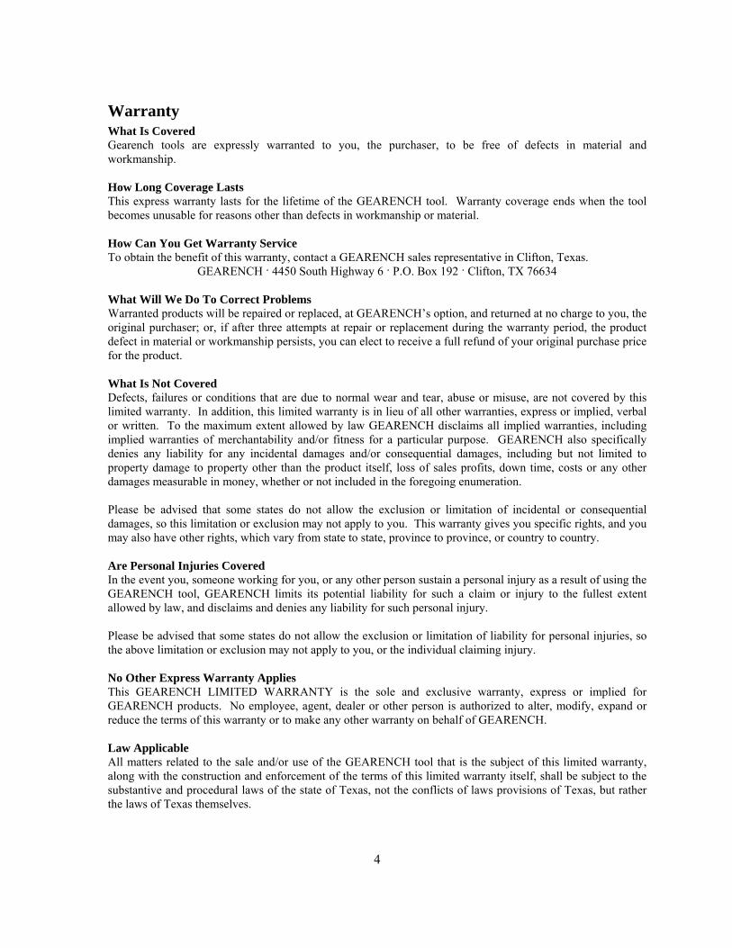
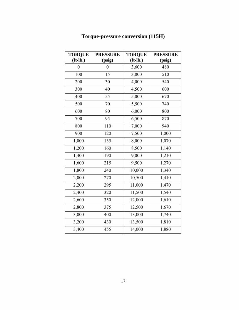
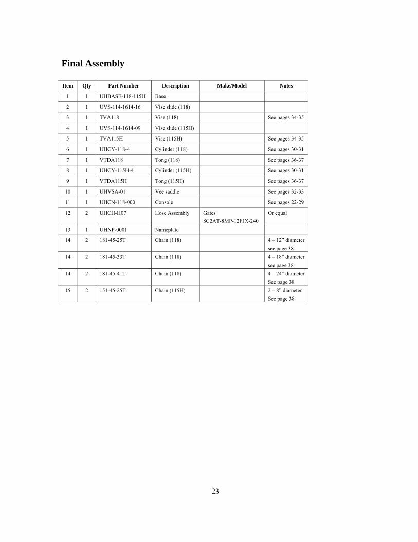
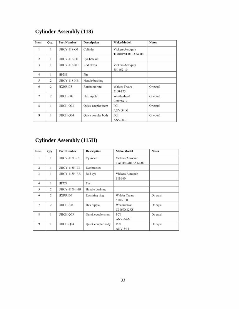
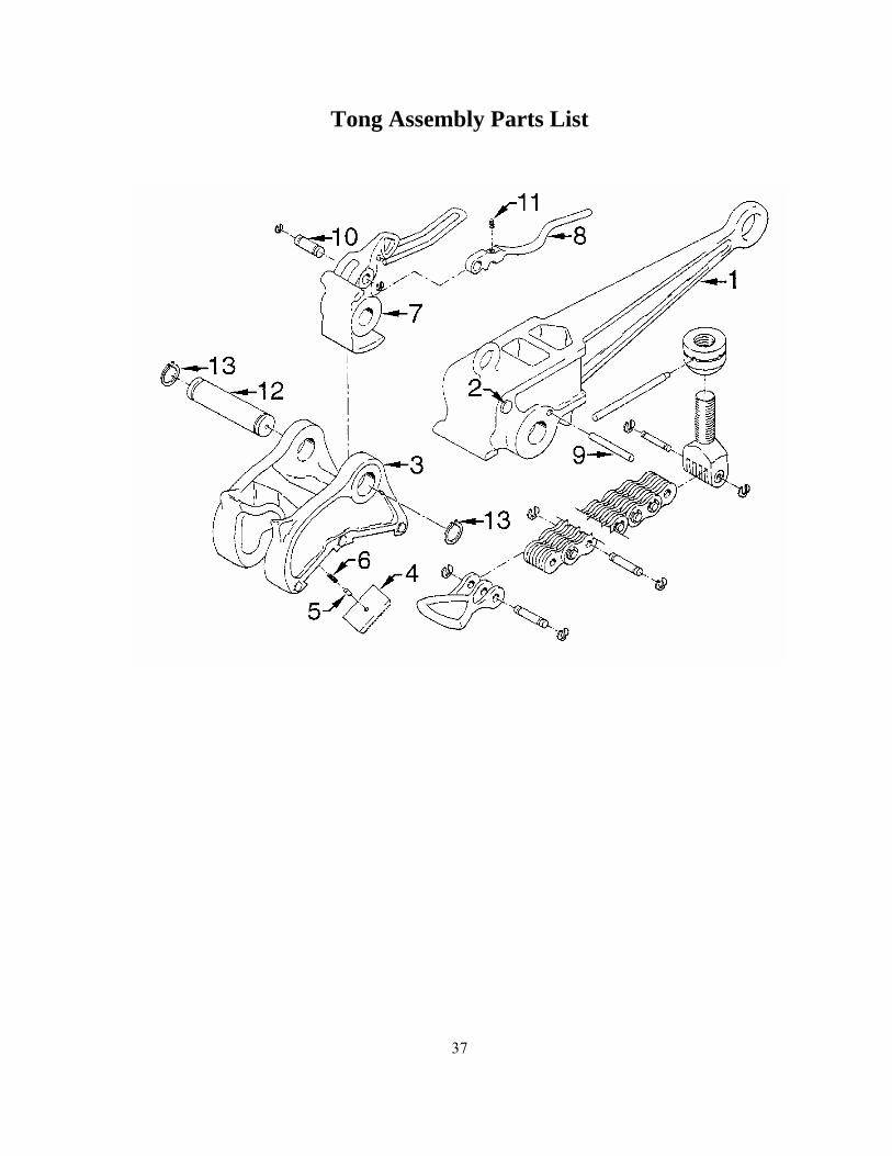
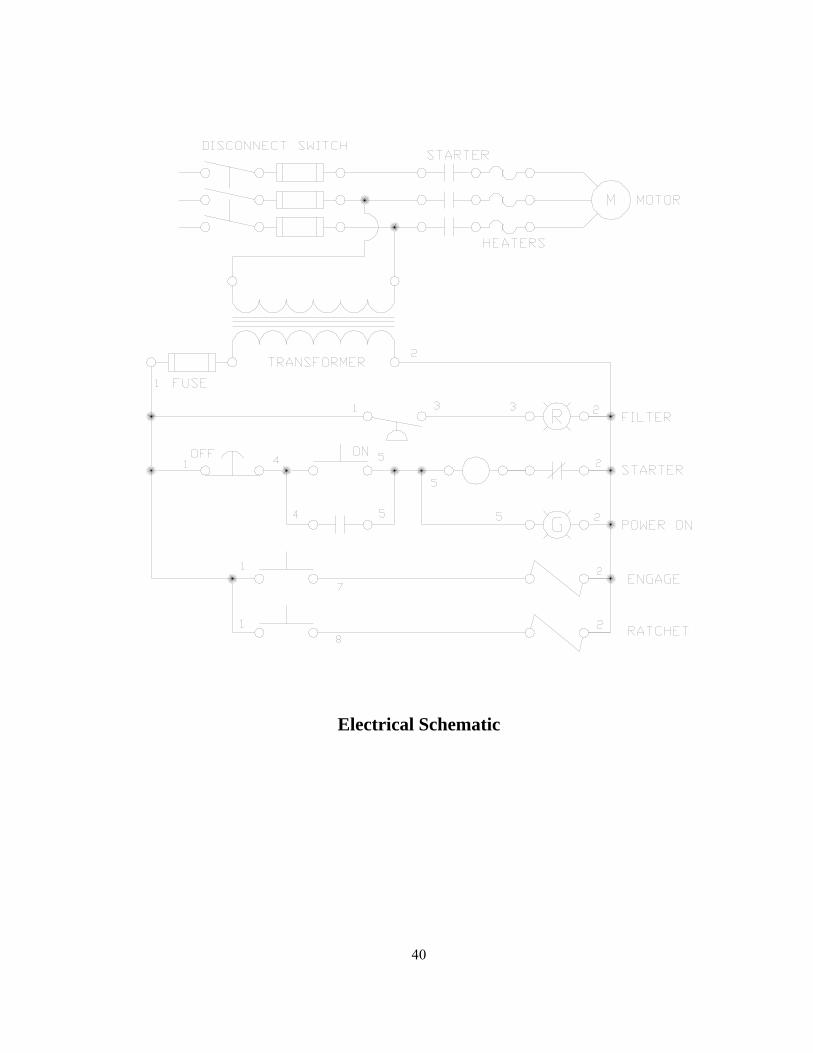
Electrical Schematic
40


