QIWS/002 - Metal Inert Gas Welding - 1 -
Tutor Pack
EAL Level 1 Award in Introductory Welding Skills Unit: QIWS-002 - Metal Inert Gas Welding
Issue1.0

QIWS/002 - Metal Inert Gas Welding - 2 -
Contents
Page
Section 1 : Introduction
3
Section 2 : Guidance on assessment
4
Section 3 : Self study pack
5
Section 4 : Welding procedure specifications and assessment sheets
17
Section 5 : Knowledge questions
27
Section 6 : Knowledge answers
30
Section 7 : Declaration of completion
33

QIWS/002 - Metal Inert Gas Welding 3
Section 1: Introduction This self study booklet is provided to support your learning and prepare you to complete the knowledge
questions provided. You should read this and complete it with support from your tutor and upon
completing the qualification you should retain the booklet as a useful resource about the welding
process you have completed. It also contains the Welding Procedure Specifications (WPS) that detail the
requirements of the 5 five practical tests you must attempt to complete the qualification.
During this qualification you will develop the practical skills required to perform Metal Arc Gas Shielded
Welding (MAGS) welding in the flat and horizontal/vertical positions. You will produce welds and
visually assess that they are fit for propose against the requirements of the weld procedure (WPS)
provided within the unit internal assessment. Furthermore you will learn the fundamental underpinning
knowledge relevant to the MAGS welding process including, safety, use of equipment and choice of
consumables.
This Qualification is intended to provide a level of knowledge that will allow fundamental welding to
take place safely and provide the base level of knowledge and skill to allow progression onto level 2
qualifications.
This booklet covers the six learning outcomes of the qualification:
Learning outcome:
Assessment method:
1. Produce beads on plate in the PA flat position
Practical task
2. Produce a lap fillet weld in the PB horizontal/vertical position
Practical task
3. Produce a tee fillet weld in the PA flat position
Practical task
4. Produce a tee fillet weld in the PB horizontal/vertical position
Practical task
5. Produce a corner weld in the PA flat position
Practical task
6. Know the Process and Health & Safety requirements of MAGS welding
Knowledge test
All the assessments must be competed in line with the assessment guidance provided and signed off by your tutor. All work should be retained for inspection by the EAL External Verifier if requested.
QIWS/002 - Metal Inert Gas Welding 4
Section 2: Guidance on Assessment Guidance on the completion and assessment of the welds
1. All welding plate blanks to be at least 150mm by 50mm
2. All MAGS welding tests to be completed using1.5 – 6.0mm Low Carbon Steel
3. All welds to be single run
4. No stop start requirements on tests (however it is recommended this is practiced)
5. All weld testing is visual only (however it is recommended macro etch is demonstrated)
6. All weld assessment must be recorded on the provided sheet and retained
7. Tasks should take no more than 45 minutes
Guidance on the completion of the knowledge questions
1. All questions must be attempted
2. This is an open book assessment
3. Any questions completed incorrectly must be discussed verbally with your tutor until they are satisfied you have understood
4. Answer sheets should be signed off and retained
QIWS/002 - Metal Inert Gas Welding 5
Section 3 : Self study pack
Learning Outcome 6: Know the Process and Health & Safety requirements of MAGS welding
Process description:
A d.c. welding power supply is used to create an electric arc between a consumable electrode wire and the metals to be welded
The heat melts both the end of the electrode wire and work surface to form a molten
weld pool and the wire is fed continuously into the weld pool
The shielding gas and consumable electrode wire come from the nozzle of the welding gun. The shielding gas is fed from the gas cylinder through the regulators to the nozzle.
The flow of gas is controlled by a gas switch that stops the gas supply when you take
your finger off the trigger.
The electrode wire is fed by a motor through the drive wheels and into the liner and out through the contact tip. The current (amperage) is linked to the wire feed rate so it goes up and down with increased or decreased wire feed. The wire picks up the current at the contact tip
MAGS welding is a versatile process that is suitable for welding a large range of
materials and thicknesses. It is used extensively in high productivity work but can be prone to fusion and penetration defects. To overcome these problems welders must have a good understanding of the importance of setting up and maintaining component parts correctly
Further information on MAGS welding can be found at
http://www.twi.co.uk/content/jk4.html

QIWS/002 - Metal Inert Gas Welding 6
Health and Safety with MAGS There are hazards associated with MAGS welding. (Discuss each with your tutor and consider what actually causes the danger and how you can reduce the danger to your self and others whilst welding)
Compressed Gas
Cylinders
Hot metal and spatter
Fire and explosion
Fumes and Noise
Arc radiation and burns
Electric Shock
Hazards

QIWS/002 - Metal Inert Gas Welding 7
Personal Protective Equipment (PPE)
Protect yourself and others from Arc Radiation and Burns by wearing and using the correct PPE!
Wear the correct welding helmet with the correct grade of filter glass fitted (check it!)
Wear chrome leather gauntlets, welding overalls and steel toe capped boots in good serviceable condition
Exposure to welding arc can cause:
Skin burns like a very bad sunburn (ultra violet light) Fatigue and tiredness (infra red light) Arc eye (severe irritation to the eye –watering eyes and partial loss of vision), occurs
4-8 hours after exposure and painful Beware of arc radiation from reflective surfaces Use screens around your work area to protect others
QIWS/002 - Metal Inert Gas Welding 8
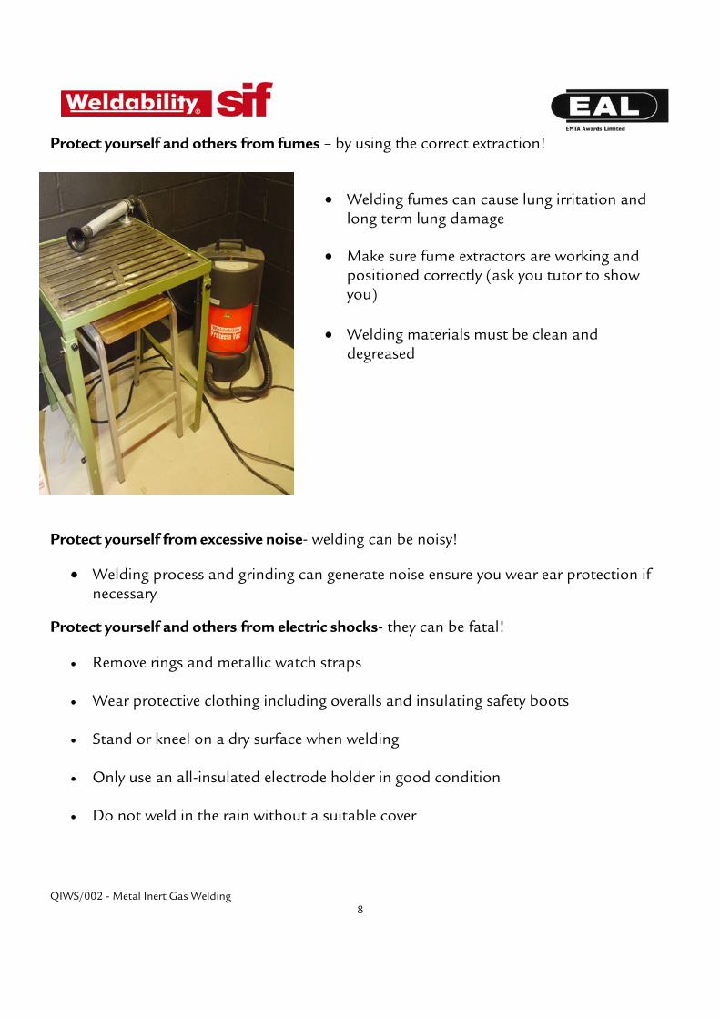
Protect yourself and others from fumes – by using the correct extraction!
Welding fumes can cause lung irritation and long term lung damage
Make sure fume extractors are working and positioned correctly (ask you tutor to show you)
Welding materials must be clean and degreased
Protect yourself from excessive noise- welding can be noisy!
Welding process and grinding can generate noise ensure you wear ear protection if necessary
Protect yourself and others from electric shocks- they can be fatal!
Remove rings and metallic watch straps
Wear protective clothing including overalls and insulating safety boots
Stand or kneel on a dry surface when welding
Only use an all-insulated electrode holder in good condition
Do not weld in the rain without a suitable cover

QIWS/002 - Metal Inert Gas Welding 9
Protect yourself and others from fire – fires start easily!
Remove any flammable material from the welding area
Beware of containers that may have contained flammable materials
Know where CO2 or powder fire extinguishers are kept (for use on electrical equipment)
Ensure your tutor has explained to you how to use the correct type of fire extinguisher
Be aware of fire exits and the evacuation procedure
Type and use of fire extinguishers – learn the right extinguisher for the right job
Class of Fire
Extinguisher Type (Coloured band on red body with white writing)
Water Foam Powder CO 2
Paper, Wood, Textiles, Fabric
Flammable Liquids
Flammable Gases
Electrical Equipment
Transport, Domestic eg boats, cars, caravans, the home

QIWS/002 - Metal Inert Gas Welding 10
Explosions – consider what you are actually welding!
There is a great danger of explosion or fire when welding containers that have previously contained explosive or flammable substances, such as petrol or oil; flammable materials can be trapped in:
grooves seams riveted joints
Never weld old oil cans or petrol tanks unless before welding, the following action must be carried out:
Remove explosive materials by steaming out with a low pressure steam cleaner and before welding the atmosphere inside the container must be certified as safe.
Compressed gas cylinders – always treat with respect! Cylinders of compressed gas must always be treated with respect; great care should be taken in moving them around the workshop, connecting them to welding equipment and in their storage. Safety rules include: Moving cylinders
Always use an approved type of cylinder trolley to move cylinders
Never move cylinders with their regulators attached
If necessary to move by hand it should only be over short distances
Always ensure your pathway is clear before starting to move a cylinder
Never move cylinders over cables etc

QIWS/002 - Metal Inert Gas Welding 11
Safety signs - protect yourself and others
Prohibition signs – must be obeyed Circular signs with red surround and diagonal red line.
NO SMOKING
Mandatory signs – must be carried out Circular blue signs
WEAR EYE PROTECTION
Warning signs – warns of hazard or danger Yellow triangular signs with black symbol and surround
DANGER HIGHLY FLAMMABLE
Information signs – to advise Green square signs
FIRE EXIT
All taken from http://www.onlinesign.com/build_sign.php?pic=58

QIWS/002 - Metal Inert Gas Welding 12
What equipment do you use for MAGS welding?
The photo shows the main parts of the MAGS/MAGS welding equipment set up in a typical welding booth.
Ask your tutor to show you and identify each equipment
component listed below.
(PPE) Personal protective
equipment Gloves
Welding helmet Boots
Overalls
MIG/MAGS (power source)
conduit/harnesswelding gun wire feed return lead
Consumables Electrode wire uses:
contact tip liner
Shielding gas: gas cylinder regulators flow meter
Tools and equipment Wire brush
Work bench Welding booth and
curtains Extraction
QIWS/002 - Metal Inert Gas Welding 13
The welding set (power source) The MAGS welding machine uses a DC transformer rectifier (A rectifier is an electrical device that converts alternating current (AC), which periodically reverses direction, to direct current (DC), which is in only one direction, a process known as rectification.) Voltage control The voltage can be controlled by using a dial on the welding machine. The voltage may need to be varied according to:
the electrode wire diameter the type of transfer of the electrode wire the type of metal being worked on
Electrical connections There are two cables connected to and from the welding machine:
the welding lead (harness or conduit) the welding return attached to the return clamp
The welding machine will have its own separate electrical earth lead.
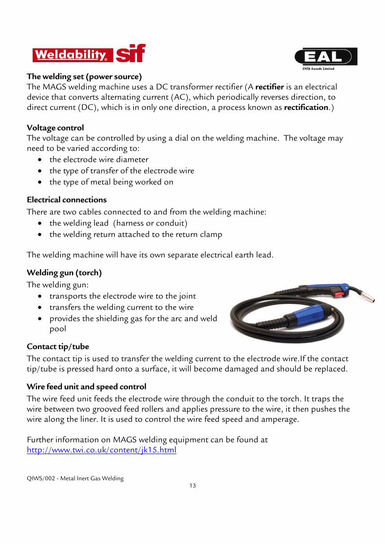
Welding gun (torch) The welding gun:
transports the electrode wire to the joint transfers the welding current to the wire provides the shielding gas for the arc and weld
pool
Contact tip/tube The contact tip is used to transfer the welding current to the electrode wire.If the contact tip/tube is pressed hard onto a surface, it will become damaged and should be replaced.
Wire feed unit and speed control The wire feed unit feeds the electrode wire through the conduit to the torch. It traps the wire between two grooved feed rollers and applies pressure to the wire, it then pushes the wire along the liner. It is used to control the wire feed speed and amperage.
Further information on MAGS welding equipment can be found at http://www.twi.co.uk/content/jk15.html
QIWS/002 - Metal Inert Gas Welding 14
Burn-back If the electrode wire fuses to the contact tip it is known as a burn back. This can be caused by too high a voltage setting. To overcome a burn-back:
Stop pressing the trigger Remove the gas nozzle to free the wire using wire cutters If the wire is fused tight remove the contact tip and snip the wire behind it.
Welding consumables
Shielding gas The shield gases are usually mixtures of argon, oxygen, CO2 and helium, which are provided in cylinders or piped into workshop. The pressure regulator on the cylinder allows the operator to adjust the gas flow rate for the type of welding. There is a flow meter on the cylinder to show the flow rate.
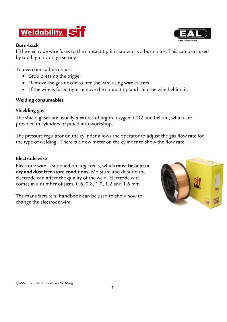
Electrode wire Electrode wire is supplied on large reels, which must be kept in dry and dust free store conditions. Moisture and dust on the electrode can affect the quality of the weld. Electrode wire comes in a number of sizes, 0.6, 0.8, 1.0, 1.2 and 1.6 mm The manufacturers’ handbook can be used to show how to change the electrode wire

QIWS/002 - Metal Inert Gas Welding 15
Starting to Weld
Striking the arc
Hold the nozzle of the welding gun above the work at the correct angles of slope and tilt (check with your tutor)
Press the trigger Electrode wire will be fed out of nozzle of gun and arc on contact with work surface Continue to press the trigger Wire will continue to be fed out of the nozzle Continue to move the welding gun along in the direction of the weld
Making a good weld relies on:
Using the correct electrode wire The correct shielding gas and flow and pressure rate of gas The correct current and voltage settings Keeping the arc length consistent at about 2.5mm Consistent speed and angles of slope and tilt of electrode movement along the plate making smooth joins when stop and start mid way through a weld
Modes of metal transfer - ask your tutor to demonstrate There are four main methods of transferring the electrode wire across the arc into the weld pool they are used for different thicknesses, type and uses of metal. :
In dip transfer the wire actually dips into the weld metal and short circuits, this is used when welding thinner materials and is useable in all welding positions, you can hear the crackling sound as the wire short circuits
Spray transfer created by turning up the settings and the electrode wire actually vaporises before it touches the surface of the work, used for thick materials and where deep penetration is needed
In pulse transfer a pulsed current is applied to the electrode wire, need a pulse welding set
Globular transfer uses carbon dioxide as shielding gas. This is used to deposit large amounts of metal, not used very often and can create lost of spatter
QIWS/002 - Metal Inert Gas Welding 16
Possible defects with welds
Defect name Possible reason for defect
Poor weld appearance Bad technique or machine not set up correctly – check with your tutor
Excessive spatter Settings incorrect – check with your tutor
Undercut Poor technique - ask your tutor to show you
Lack of fusion/penetration Poor technique or settings too low
Porous weld Lack of shielding gas or dirty plate - check flow meter and material cleanliness
Weld too wide or too narrow
Poor technique, moving too fast or too slow- ask your tutor to show you
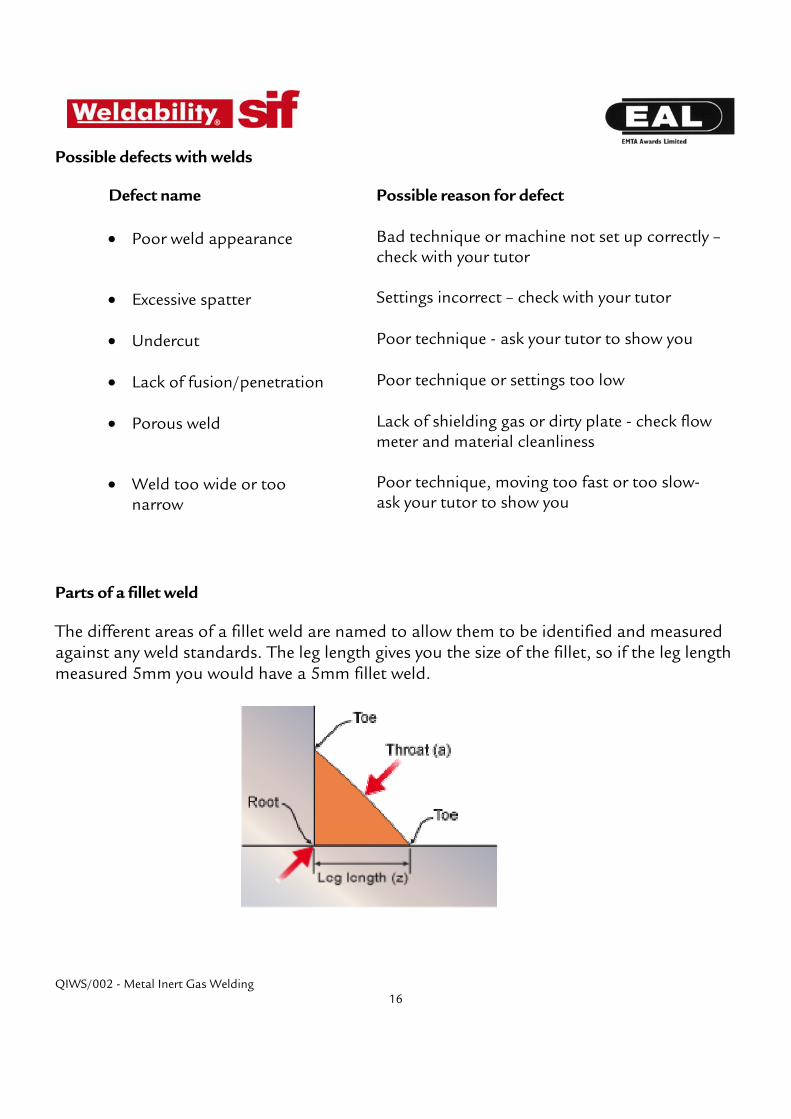
Parts of a fillet weld
The different areas of a fillet weld are named to allow them to be identified and measured against any weld standards. The leg length gives you the size of the fillet, so if the leg length measured 5mm you would have a 5mm fillet weld.

QIWS/002 - Metal Inert Gas Welding 17
Section 4 : Welding procedure specifications and assessment sheets
Welding Procedure Specification:
Learning Outcome 1 – Beads on Plate in the flat (PA) position (MAGS)
Joint type: Beads on plate
Welding position: PA
Parent Material Type: Low carbon steel (LCS)
Dimension of test piece:
Thickness: 1.5 -6mm.
Length: 150mm minimum.
Width: 50mm minimum
Weld preparation Plates should be degreased and wire brushed prior to welding
Run sequence and completed weld
Method of Preparation and Cleaning: Degrease / mechanical dressing / wire brush.
Run No. Electrode wire dia
Amperage (range)
Arc Voltage (range)
Polarity Gas Flow Rate:
1 and remainder 0.8 -1.0 80-120 17-20 dc +ve 8 – 15 l/min
Other Information: Two parallel weld beads to be completed for full length of plate There is no requirement to complete a stop start on this weld but if one is attempted it will be assessed along with the weld.
Remove any slag and spatter and clean weld with wire brush, do not grind finished weld surface, avoid surface damage. Welding Consumables:
Filler material: Suitable carbon steel solid wire
Composition: In accordance with BS EN440: 1995
Shielding gas: Argon/CO2/Oxygen mix
Non destructive testing: Visual examination only – details on assessment sheet

QIWS/002 - Metal Inert Gas Welding 18
Learning Outcome 1 – Beads on Plate in the flat (PA) position (MAGS)
All essential items and 2 from 3 desirable must pass assessment
Learner name: Date of completion:
Decision Pass Fail Assessor Comments 1. Uniformity The weld is uniform and width does not vary more than 4mm along length (desirable)
The weld toes blend without cold lapping (essential)
The weld reinforcement is of even height along weld length (essential)
The weld is free from cracking (essential)
No single cavity or inclusion is more than 3mm in any direction or any group more than 3m in total (essential)
2. Undercut Undercutting (intermittent) does not exceed 1.5mm depth (desirable)
Undercutting does not exceed 50% of total weld length(desirable)
No single undercutting exceeds 25mm (desirable)
Assessor General Comment
Assessor Signature
Learner Signature
Pass Mark (delete as appropriate) Task Pass/Fail
Date of re-assessment (if applicable)

QIWS/002 - Metal Inert Gas Welding 19
Welding Procedure Specification:
Learning Outcome 2 – Lap fillet in the horizontal/vertical (PB) position (MAGS)
Joint type: Lap fillet
Welding position: PB
Parent Material Type: Low carbon steel (LCS)
Dimension of test piece:
Thickness: 1.5 -6mm.
Length: 150mm minimum.
Width: 50mm minimum
Weld preparation
Run sequence and completed weld
Method of Preparation and Cleaning: Degrease / mechanical dressing / wire brush.
Run No. Electrode wire dia
Amperage (range)
Arc Voltage (range)
Polarity Gas Flow Rate:
1 and remainder 0.8 -1.0 80-120 17-20 dc +ve 8 – 15 l/min
Other Information: Ensure plates are clamped and tack welded prior to welding There is no requirement to complete a stop start on this weld but if one is attempted it will be assessed along with the weld.
Remove any slag and spatter and clean weld with wire brush, do not grind finished weld surface, avoid surface damage. Welding Consumables:
Filler material: Suitable carbon steel solid wire
Composition: In accordance with BS EN440: 1995
Shielding gas: Argon/CO2/Oxygen mix
Non destructive testing: Visual examination only – details on assessment sheet

QIWS/002 - Metal Inert Gas Welding 20
Learning Outcome 2 – Lap fillet in horizontal/vertical (PB) position (MAGS)
All essential items and 3 from 5 desirable must pass assessment
Learner name: Date of completion:
Decision Pass Fail Assessor Comments 1. Alignment Linear misalignment should not exceed +/- 3mm of centre line (desirable)
2. Uniformity The weld is uniform and width does not vary more than +/- 3mm along length (desirable)
Leg length must not exceed metal thickness + 2mm (essential)
The weld toes blend without cold lapping (essential)
The weld reinforcement is of even height along weld length (essential)
The weld is free from cracking (essential)
No single cavity or inclusion is more than 3mm in any direction or any group more than 3m in total (essential)
3. Undercut Undercutting (intermittent) does not exceed 1.5mm depth (desirable)
Undercutting does not exceed 50% of total weld length(desirable)
No single undercutting exceeds 25mm (desirable)
Assessor General Comment
Assessor Signature
Learner Signature
Pass Mark (delete as appropriate) Task Pass/Fail
Date of re-assessment (if applicable)

QIWS/002 - Metal Inert Gas Welding 21
Welding Procedure Specification:
Learning Outcome 3 – Tee fillet in the flat (PA) position (MAGS)
Joint type: Tee fillet
Welding position: PA
Parent Material Type: Low carbon steel (LCS)
Dimension of test piece:
Thickness: 1.5 -6mm.
Length: 150mm minimum.
Width: 50mm minimum
Weld preparation
Run sequence and completed weld
Method of Preparation and Cleaning: Degrease / mechanical dressing / wire brush.
Run No. Electrode wire dia
Amperage (range)
Arc Voltage (range)
Polarity Gas Flow Rate:
1 and remainder 0.8 -1.0 80-120 17-20 dc +ve 8 – 15 l/min
Other Information: Ensure plates are clamped and tack welded prior to welding There is no requirement to complete a stop start on this weld but if one is attempted it will be assessed along with the weld.
Remove any slag and spatter and clean weld with wire brush, do not grind finished weld surface, avoid surface damage. Welding Consumables:
Filler material: Suitable carbon steel solid wire
Composition: In accordance with BS EN440: 1995
Shielding gas: Argon/CO2/Oxygen mix
Non destructive testing: Visual examination only – details on assessment sheet
450

QIWS/002 - Metal Inert Gas Welding 22
Learning Outcome 3 – Tee fillet in the flat (PA) position (MAGS)
All essential items and 3 from 6 desirable must pass assessment
Learner name: Date of completion:
Decision Pass Fail Assessor Comments 1. Alignment Linear misalignment should not exceed +/- 3mm of centre line (desirable)
Angular alignment is within +/_ 50 from 900
(desirable)
2. Uniformity The weld is uniform and width does not vary more than +/- 3mm along length (desirable)
Leg length must not exceed metal thickness + 2mm (essential)
The weld toes blend without cold lapping (essential)
The weld reinforcement is of even height along weld length (essential)
The weld is free from cracking (essential)
No single cavity or inclusion is more than 3mm in any direction or any group more than 3m in total (essential)
3. Undercut Undercutting (intermittent) does not exceed 1.5mm depth (desirable)
Undercutting does not exceed 50% of total weld length(desirable)
No single undercutting exceeds 25mm (desirable)
Assessor General Comment
Assessor Signature
Learner Signature
Pass Mark (delete as appropriate) Task Pass/Fail
Date of re-assessment (if applicable)

QIWS/002 - Metal Inert Gas Welding 23
Welding Procedure Specification:
Learning Outcome 4 – Tee fillet in the horizontal/vertical (PB) position (MAGS)
Joint type: Tee fillet
Welding position: PB
Parent Material Type: Low carbon steel (LCS)
Dimension of test piece:
Thickness: 1.5 -6mm.
Length: 150mm minimum.
Width: 50mm minimum
Weld preparation
Run sequence and completed weld
Method of Preparation and Cleaning: Degrease / mechanical dressing / wire brush.
Run No. Electrode wire dia
Amperage (range)
Arc Voltage (range)
Polarity Gas Flow Rate:
1 and remainder 0.8 -1.0 80-120 17-20 dc +ve 8 – 15 l/min
Other Information: Ensure plates are clamped and tack welded prior to welding There is no requirement to complete a stop start on this weld but if one is attempted it will be assessed along with the weld.
Remove any slag and spatter and clean weld with wire brush, do not grind finished weld surface, avoid surface damage. Welding Consumables:
Filler material: Suitable carbon steel solid wire
Composition: In accordance with BS EN440: 1995
Shielding gas: Argon/CO2/Oxygen mix
Non destructive testing: Visual examination only – details on assessment sheet

QIWS/002 - Metal Inert Gas Welding 24
Learning Outcome 4 – Tee fillet in horizontal/vertical (PB) position (MAGS)
All essential items and 3 from 6 desirable must pass assessment
Learner name: Date of completion:
Decision Pass Fail Assessor Comments 1. Alignment Linear misalignment should not exceed +/- 3mm of centre line (desirable)
Angular alignment is within +/_ 50 from 900
(desirable)
2. Uniformity The weld is uniform and width does not vary more than +/- 3mm along length (desirable)
Leg length must not exceed metal thickness + 2mm (essential)
The weld toes blend without cold lapping (essential)
The weld reinforcement is of even height along weld length (essential)
The weld is free from cracking (essential)
No single cavity or inclusion is more than 3mm in any direction or any group more than 3m in total (essential)
3. Undercut Undercutting (intermittent) does not exceed 1.5mm depth (desirable)
Undercutting does not exceed 50% of total weld length(desirable)
No single undercutting exceeds 25mm (desirable)
Assessor General Comment
Assessor Signature
Learner Signature
Pass Mark (delete as appropriate) Task Pass/Fail
Date of re-assessment (if applicable)

QIWS/002 - Metal Inert Gas Welding 25
Welding Procedure Specification:
Learning Outcome 5 – Corner weld in the flat (PA) position (MAGS)
Joint type: Outside corner
Welding position: PA
Parent Material Type: Low carbon steel (LCS)
Dimension of test piece:
Thickness: 1.5 -6mm.
Length: 150mm minimum.
Width: 50mm minimum
Weld preparation
Run sequence and completed weld
Method of Preparation and Cleaning: Degrease / mechanical dressing / wire brush.
Run No. Electrode wire dia
Amperage (range)
Arc Voltage (range)
Polarity Gas Flow Rate:
1 and remainder 0.8 -1.0 80-120 17-20 dc +ve 8 – 15 l/min
Other Information: Ensure plates are clamped and tack welded prior to welding There is no requirement to complete a stop start on this weld but if one is attempted it will be assessed along with the weld.
Remove any slag and spatter and clean weld with wire brush, do not grind finished weld surface, avoid surface damage. Welding Consumables:
Filler material: Suitable carbon steel solid wire
Composition: In accordance with BS EN440: 1995
Shielding gas: Argon/CO2/Oxygen mix
Non destructive testing: Visual examination only – details on assessment sheet

QIWS/002 - Metal Inert Gas Welding 26
Learning Outcome 5 – Corner weld in the flat (PA) position (MAGS)
All essential items and 4 from 7 desirable must pass assessment
Learner name: Date of completion:
Decision Pass Fail Assessor Comments 1. Alignment Angular alignment is within +/_ 50 from 900
(desirable)
2. Uniformity The weld is of uniform width of face (desirable)
The weld ripples are consistent and without excessive undulation (essential)
The weld toes blend without cold lapping (essential)
The weld profile is rounded (essential)
The weld is free from cracking (essential)
No single cavity or inclusion is more than 3mm in any direction or any group more than 3m in total (essential)
3. Undercut Undercutting (intermittent) does not exceed 1.5mm depth (desirable)
Undercutting does not exceed 50% of total weld length(desirable)
No single undercutting exceeds 25mm (desirable)
Assessor General Comment
Assessor Signature
Learner Signature
Pass Mark (delete as appropriate) Task Pass/Fail
Date of re-assessment (if applicable)

QIWS/002 - Metal Inert Gas Welding 27
Section 5 : Knowledge questions (MAGS)
1. Complete the diagram below showing the main hazards of MAG welding.
2. What is the most likely cause of excessive “spatter” during MAGS welding?
3. Identify the type and position of weld in the diagram below. Weld type is:……………………………………. Position is:……………………………………….
Continued on next page
Fire and explosion
Hazards

QIWS/002 - Metal Inert Gas Welding 28
4. What is “arc eye”? 5. How would you overcome a burnback in your contact tip/tube? 6. List the four modes of metal transfer in MAG welding? 7. What are the main items of equipment used in MAGS Welding? Complete the diagram below.
Continued on next page
What equipment do
you use?
MIG/MAGS (power source) conduit/harness -welding gun -wire feed -return lead

QIWS/002 - Metal Inert Gas Welding 29
8. List the main defects found in MAGS welds? 9. What does D.C. mean? 10. Why is it important to erect screens around the welding area?

QIWS/002 - Metal Inert Gas Welding 30
Section 5 : Knowledge questions - solutions
1. Complete the diagram showing the main hazards of MAG welding.
2.What is the most likely cause of excessive “spatter” during welding?
Too much wire/amps Incorrect settings Poor technique
3. Identify the type and position of weld in the diagram below.
Weld type is:………Corner joint……………. Position is:……Flat (PA)….
Continued on next page
Hot metal and splatter
Fire and explosion
Fumes
Arc radiation and burns
Electric Shock
Hazards

QIWS/002 - Metal Inert Gas Welding 31
4. What is “arc eye”?
Severe irritation to the eye –watering eyes and partial loss of vision, this occurs 4-8 hours after exposure to arc radiation
5. How would you overcome a burn back in your contact tip/tube?
Stop pressing the trigger Remove the gas nozzle to free the wire using wire cutters If the wire is fused tight remove the contact tip and snip the wire behind it.
6. List the main modes of metal transfer in MAG welding?
dip spray pulse globular
7. What are the main items of equipment used for MAGsWelding? Complete the diagram below.
Continued on next page
What equipmentdo you use?
(PPE) Personal protective
equipment Gloves
Welding helmet Boots
Overalls
MIG/MAGS (power source)
conduit/harness -welding gun -wire feed -return lead
Consumables Electrode wire uses:
-contact tip -liner
Shielding gas uses:-regulators -flow meter
Tools and equipment Wire brush
Work bench Welding booth and
curtains Extraction

QIWS/002 - Metal Inert Gas Welding 32
8. List the main defects found in welds
Poor weld appearance Excessive splatter Poor penetration of the weld Porous weld Weld too wide or too narrow
9. What does D.C. mean ?
direct current 10. Why is it important to erect screens around the welding area?
To protect other people from arc radiation

QIWS/002 - Metal Inert Gas Welding 33
Section 7 : Declaration of completion – Unit 002 MAGS
Learner name: Date of completion:
Assessor name: Centre Name:
Task details Date completed
Assessor signature
1. Produce beads on plate in the PA flat position
2. Produce a lap fillet weld in the PB horizontal/vertical position
3. Produce a tee fillet weld in the PA flat position
4. Produce a tee fillet weld in the PB horizontal/vertical position
5. Produce a corner weld in the PA flat position
6. Know the Process and Health & Safety requirements of MAGS welding – knowledge test
Assessor General Comment
Assessor Signature
Learner Signature
© 2011 EMTA Awards Limited All rights reserved. No part of this publication may be reproduced, stored in a retrieval system, or transmitted, in any form or by any means, electronic, mechanical, photocopying, recording or otherwise, without the prior written permission of EAL EMTA Awards Limited Requests should be made in writing and addressed to: Product Development, EAL EMTA Awards Limited, 3365 Century Way, Thorpe Park, Leeds LS15 8ZB.


