1 JUNE 2012 TS TIDINGS
TECHNICAL SERVICES / PSSR
PAGUHTAN CCPP JUNE 2012 VOLUME : 16.01
Published by Technical Services / PSSR For internal circulation
HIGHLIGHTS
NEYVELI TS II EXP CFBC, 2 X 250 MW, UNIT 2:
TG OIL FLUSHING COMPLETED
NORTH CHENNAI TPS II 2 X 600 MW: UNIT 2 :
BOILER LIGHTED UP
BOILER CHEMICAL CLEANING WITH AMMONIATED EDTA WAS COMPLETED.
--ooOOoo--
2 JUNE 2012 TS TIDINGS
TECHNICAL SERVICES / PSSR
INSIDE
1. STATUS OF PROJECTS COMMISSIONED / TO BE COMMISSIONED DURING 2010 - 2012.
2. SERVICE RENDERED TO OTHER REGIONS/SAS/PROJECTS AFTER CONTRACT
CLOSING/CUSTOMER TRAINING.
3. APPRECIATION FROM CUSTOMER FOR SERVICES RENDERED.
4. FEED BACK ON EQUIPMENTS FROM SITES.
5. LET US KNOW. CHEMICAL TREATMENT FOR SEA WATER USED AS COOLING
MEDIUM
Feed backs and suggestions from all departments of BHEL for improvement of TS TIDINGS are welcome and may please be addressed to ADDL. GENERAL MANAGER (TSX)/BHEL-PSSR/CHENNAI
3 JUNE 2012 TS TIDINGS
TECHNICAL SERVICES / PSSR
STATUS OF PROJECTS COMMISSIONED / TO BE COMMISSIONED DURING 2010 – 2012: BELLARY 500 MW UNIT 2:
Mill – G interlock & protection was demonstrated to customer. Mill – G coupled trial run was done. Roller setting completed on 02.06.2012
SGC logics of TG DMCW for two pumps was demonstrated to customer.
CW-C motor - 8 hours trial run completed.
Main Turbine lift check with jacking oil was carried out jointly with customer and Turbine was put on barring gear on 07.06.12. TG waste fluid tank level switch calibration completed.
SAT 02 Transformer stability test, REF differential relay setting completed on 07.06.12.
AHP dry ash system TAC 02 motor no load trial run was completed.
Generator Primary water level transmitter calibration was carried out.
RODM HCL transfer pump motor was commissioned and run on 09.06.12. RODM-UF plant was started on 12.06.12 for DM water generation and flushing of RO stages 1 & 2 MB system was carried out.
FD fan – A 3.3 KV HT cable HV test was completed on 11.06.2012.
Clarifier water second source Transformer interlock protection and scheme checking completed.
PA fan – A 3.3 KV HT cable HV test was carried out.
Boiler blow down pump – 01 motor no load trial run was carried out.
TDBFP – B : Barring gear trial run was carried out for four hours. Recirculation valve commissioned from remote. Leak off steam control valve fine tuning completed. Exhaust-hood spray line flushing completed. Turbine interlocks & protection jointly checked with customer. Turbine rolled with auxiliary PRDS on 27.06.12 for solo run trial.
4 JUNE 2012 TS TIDINGS
TECHNICAL SERVICES / PSSR
After attending to actuator defects by M/s Rotork Engineer, 7 nos. of bunker outlet gate remote operation was demonstrated to customer.
SADC remote checking with customer Engineers was carried out.
ESP B pass – 2 transformer and ESP D pass transformer # 1 11 KV HT cable HV test completed.
ESP A pass : ACE 1 upstream, downstream and incomer breakers testing completed. CERM/ EERM motors module testing completed.
Logic equalization of unit 2 with unit 1 of MFT and purge circuit completed.
Clean air flow test of Mills – E, F & G completed.
After replacement of Mills – D & E motor NDE bearings, both the motors were run and trial run completed.
AHP – 2 nos. fluidizing air blower motors no load trial run was completed.
All ( 7 nos. ) mills steam inert line steam blowing was completed.
HBP panel to HT board synchronization circuit for OBD board was demonstrated to customer and charged.
CRH to deaerator pressure control valve CRHV 06 & CBD level control valve BD 06 commissioned from remote.
Mills E, F & G – PA duct leak test (repeat test) was carried out.
Turbine rotor axial float of thrust bearing was more (0.47 mm), the same was corrected by adding shims and bearing pedestal was boxed up.
PT plant : 2 nos. sodium hydro chlorite dosing pumps to RW was commissioned.
Coal flow monitors of feeders – A, C & D were commissioned.
RAPCON panel of ESP B, C & D pass checking completed.
Raw water PH transformer - 2 11 KV income cable HV test was completed.
5 JUNE 2012 TS TIDINGS
TECHNICAL SERVICES / PSSR
CPCL PHASE 3 - UNIT 4:
GT alignment correction was done and boxed up. Ratcheting done on 03.06.12.
GT was synchronized on 04.06.12 and reached full load.
Graphics modification in DCS completed.
Hazardous gas monitor for GT was commissioned.
M/s Bentley Nevada vibration system to DCS communication was established.
Off base skid fuel oil leak test was completed.
CEMS ( Chimney Emission Monitoring System ) was commissioned.
GT was taken upto base load of 21.5 MW and the vibration was 9 mm/sec. Report has been sent to BHEL/Hyderabad.
GT was synchronized on 30.06.12 and loaded upto 14 MW with HSD fuel.
MRPL:1XFr.5 GTG, 2X28.5 MW STG, 4X270 TPH UTILITY BOILERS, 1X85 TPH HRSG, ADDITIONAL ORDER: 1XFr.6B GTG, 1X85 TPH HRSG-GT1.
GT 1-Mist eliminator fan - B trial run was done. ELOP no load trial run was done. Auxiliary hydraulic oil pump trial run was completed. Starting diesel engine was commissioned. GT 1 was put on ratchet from Mark – VI panel. GT 1 was made ready for cranking through Mark – VI with charging of fire water in cooling water system. Customer insisted for commissioning of FRP cooling water system and fire hydrant system around GT building before proceeding for cranking.
6.6V bus differential testing was completed
All the tests were completed in PMCC – 1 & 3.
125 V DC battery charger ten hours inspection was carried out successfully.
6 JUNE 2012 TS TIDINGS
TECHNICAL SERVICES / PSSR
NEYVELI TS II EXP CFBC, 2 X 250 MW, UNIT 1:
Unit was boxed up on 20/03/12 due to SH 1.2a in FBHE-2 tube leakage. Repair works are in progress.
LRSBs were commissioned from DCS. NEYVELI TS II EXP CFBC, 2 X 250 MW, UNIT 2:
Acid cleaning for fans - SAF 2A & PAF 2A lube oil system was completed .
SA fan – 2A: Oil flushing was completed. 8 hours motor trial run was completed.
PA fan A – Lube oil system flushing was completed.
TG OIL FLUSHING COMPLETED ON 06.06.12.
DMCW – A & B motor 8 hours trial run was completed.
CEP –2A and 2B motors - 8 hrs. trial run was completed.
BFP – 2C : Lube oil flushing was completed.
TG Central lub oil system : Oil piping air blasting was completed.
RAPH – A – Support bearing and Guide bearing lube oil lines acid cleaning was completed.
ID fan – 2A lube oil system normalization was completed and oil system kept in service through bearings for flushing pedestals.
Detergent flushing of feed water system was completed.
NORTH CHENNAI TPS II 2 X 600 MW: UNIT 2 :
ID fan- 2A motor protection and auxiliary relay testing was completed.
RODM : HP pump motor relay testing was completed.
ID fan – 2A CH-1 Transformer was charged.
VFD panel testing completed.
BCW motor HIPOT test 3 nos. completed.
7 JUNE 2012 TS TIDINGS
TECHNICAL SERVICES / PSSR
OCT - To2 cable HIPOT test was completed.
Bottom ash silo MCC relay testing completed.
DC scanner fan trial run was carried out.
TG AOP 2A & 2B motor trial run completed. Jacking oil pump ( 2A & 2B ) motor trial run done.
Generator Bushing and Stator testing completed.
Unit service PMCC Transformer 1DAT02 testing carried out.
Station service PMCC Transformer ODAT01 testing carried out.
Condenser transfer pump 2A motor trial run was completed.
Boiler drum air vent, super heater vent & reheater vent commissioned from DCS.
EDTA pump – 3 was commissioned.
Boiler second cold rinsing completed.
LOTV commissioned from remote.
DC scanner fan operation checking from remote was completed.
RODM : HP pump – A bumped and pump B & C motor no load trial run was completed.
Generator stator ELCID test was carried out.
Temporary line for fire fighting of APH was completed.
Furnace boxing up was completed.
Boiler was lighted up on 22.06.12 for EDTA.
BOILER chemical cleaning with AMMONIATED EDTA AND RINSING COMPLETED.
ESP Service transformer 2DBT01 testing was carried out.
Raw water transformer protection checking completed.
8 JUNE 2012 TS TIDINGS
TECHNICAL SERVICES / PSSR
RINL:
TB- 4 is in service.
LTMCC (5DA & ODA) under voltage relays (ABB Make) testing was completed.
Testing of all HT motors completed.
Fixing of 10 MVA and 20 MVA transformer seal off bushing flexible completed.
Mill A : Stage – 1 lube oil flushing was completed.
11 KV board cleaning and bus bar tightness was done. 11 KV board breaker penetration and inter changeability test was carried out. 11 KV & 6.6 KV (OBA & OCA) bus duct HIPOT test was completed.
ID fan – B hydraulic coupling oil flushing was completed.
ACW line charging & flushing of ID fan – A & B, FD fan – A & B, PA fan – A & B, Mills and APH system were completed.
6.6 KV board ( OCB ) out going feeder inter lock and protection checking was completed.
SIMHADRI STAGE II, 2 X 500 MW, UNIT 4:
PAPH – A : Soot blower swing checking and lance setting completed. Air motor air line from air receiver tank outlet to air motor inlet air blowing completed. Fire fighting lines water flushing completed. 4 hours trial run completed. Soot blower line steam blowing completed.
SCAPH lines steam blowing for SAPH 4A & 4B completed.
PA fan – A : Lube oil motors – 4 hours trial run carried out. Stage – I lube oil flushing was completed.
Unit was lighted up on 07.06.12.
Unit was synchronized and loaded upto 150 MW. TG was hand tripped on 08.06.12 due to high vibration. Balancing of exciter rotor was carried out to reduce the vibration levels.
LRSB lines hydro test and steam blowing completed.
ESP – B pass air leak test was done.
9 JUNE 2012 TS TIDINGS
TECHNICAL SERVICES / PSSR
STERLITE - 2 X 80 MW UNIT 1 :
RAPH – 1 guide bearing and support bearing lube oil flushing is in progress.
Oil filling was completed in BFP - 1A lube oil tank. DCS system OWS and EWS PCs were charged and communication panel
was established. MAX panels MFT1, MFT2, UNIT/PURGE and OAB CAB ( Oil AB coal AB ) were
energized and communication with EWS was established. Card board blasting of LDO line from pump house was completed. DCS panels were charged and communicated with EWS. GT was back charged and kept in idle charging (Customer scope) FD fan – 1A motor trial run was completed.
VALLUR 3 X 500 MW, UNIT 1:
TDBFP A: Oil filling was completed. Lube oil line hydro test completed. TG DMCW system hydro test was carried out. Self cleaning strainer of ACW system was commissioned and protocol
signed by customer. Auxiliary Boiler was lighted up on 06.06.12 and run for four hours. TDBFP – B: Turbine bearing normalization and alignment completed.
Booster pump suction line flushing was completed. Acid cleaning of lube oil lines of Mill – G & F was completed. Mill – G main motor 8 hours trial run was done. Seal air fan – B trial run was carried out. ESP – C pass 18 fields were charged and ESP – D pass OCC & SCC tests
were completed. Boiler hydro test demonstration was carried out in the presence of
Inspector of Boiler. ESP – D pass 13 fields were charged. Boiler was lighted up on 27.06.12. Unit was loaded upto 100 MW and Unit tripped at 1500 hrs. on 30.06.12
due to no coal in bunker and machine came on barring gear on 1600 hours.
10 JUNE 2012 TS TIDINGS
TECHNICAL SERVICES / PSSR
VALLUR 3 X 500 MW, UNIT 2 FD fan A : Blade pitch controller setting completed. Trial run was
carried out. Instrument air line header card board blasting was carried out. Mill – F: Lube oil motor trial run completed. SG DMCW : Cooling water lines flushing completed upto ID fan. SAPH – A: Motor trial run was done. Service air line and instrument air line header and branch piping flushing
completed. CC pump cavity water line stage – 1 purging completed. SAPH – 2A : Oil draining of support bearing and guide bearing was completed. LDO lines & atomizing air lines air blasting was carried out. CC pump stage – II purging was completed. Furnace Air Tightness Test was carried out. LDO system : All corner valves termination and commissioning in progress.
SERVICE RENDERED TO OTHER REGIONS/SAS/PROJECTS AFTER CONTRACT
CLOSING.
--- NIL ---
CUSTOMER TRAINING & TECHNICAL PAPER PRESENTED:
Shri.P Madhusudhan, Manager/Commissioning, Vallur site was deputed to TNEB Thermal training institute as guest faculty on 16/06/2012 for delivering Lecture on “Heat Rate improvement in Thermal stations”. Operation and Maintenance engineers from various power stations of TNEB have attended the training program. APPRECIATION FROM CUSTOMER FOR SERVICES RENDERED :
--- NIL ---
11 JUNE 2012 TS TIDINGS
TECHNICAL SERVICES / PSSR
FEED BACK NO.1
PROJECT: SIMHADRI SUPER THERMAL POWER PROJECTS, NTPC, UNIT-3, 500MW PROBLEM: DAMAGE OF STAGE II FAN BLADES AND FIXED GUIDE VANES IN PA
FAN 3B.
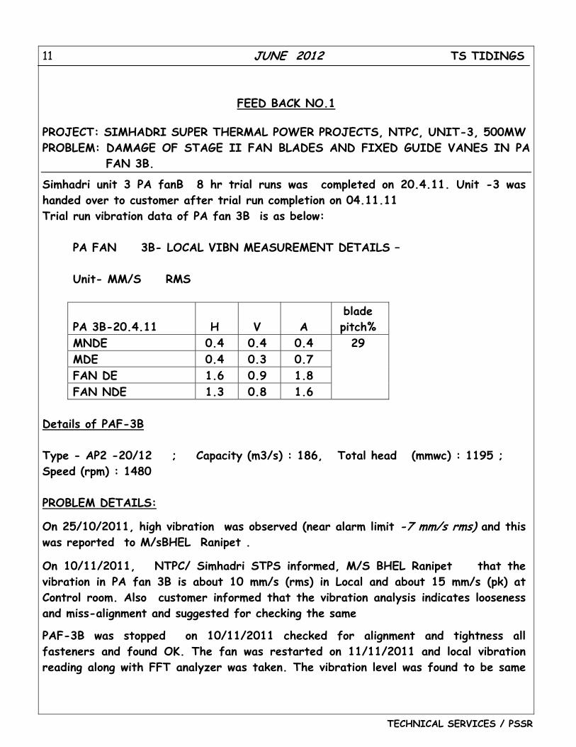
Simhadri unit 3 PA fanB 8 hr trial runs was completed on 20.4.11. Unit -3 was handed over to customer after trial run completion on 04.11.11 Trial run vibration data of PA fan 3B is as below:
PA FAN 3B- LOCAL VIBN MEASUREMENT DETAILS – Unit- MM/S RMS
PA 3B-20.4.11 H V A blade pitch%
MNDE 0.4 0.4 0.4 MDE 0.4 0.3 0.7 FAN DE 1.6 0.9 1.8 FAN NDE 1.3 0.8 1.6
29
Details of PAF-3B Type - AP2 -20/12 ; Capacity (m3/s) : 186, Total head (mmwc) : 1195 ; Speed (rpm) : 1480 PROBLEM DETAILS:
On 25/10/2011, high vibration was observed (near alarm limit -7 mm/s rms) and this was reported to M/sBHEL Ranipet .
On 10/11/2011, NTPC/ Simhadri STPS informed, M/S BHEL Ranipet that the vibration in PA fan 3B is about 10 mm/s (rms) in Local and about 15 mm/s (pk) at Control room. Also customer informed that the vibration analysis indicates looseness and miss-alignment and suggested for checking the same
PAF-3B was stopped on 10/11/2011 checked for alignment and tightness all fasteners and found OK. The fan was restarted on 11/11/2011 and local vibration reading along with FFT analyzer was taken. The vibration level was found to be same
12 JUNE 2012 TS TIDINGS
TECHNICAL SERVICES / PSSR
as earlier and subsequently found rising to 16-17 mm/s pk close to trip level of 19.8 mm/s –pk This problem was reported to Ranipet through CAR.
Ranipet engineer reached site on 17/11/2011 and recorded vibrations and , informed that there are possibility of internal looseness and mechanical rubbing inside the fan area. Beside above the following Data were also checked by Ranipet Engr in detail –
a) Operation parameter for Stalling problem if any but no such operational problem was noticed.
b) Parameters during paralleling of both fans. c) Blade pitch checking for local and control room reading matching.
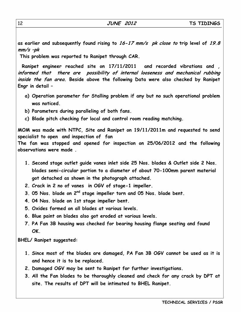
MOM was made with NTPC, Site and Ranipet on 19/11/2011m and requested to send specialist to open and inspection of fan The fan was stopped and opened for inspection on 25/06/2012 and the following observations were made .
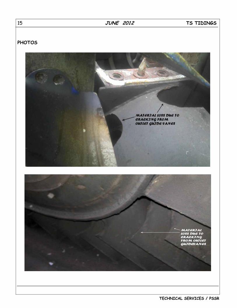
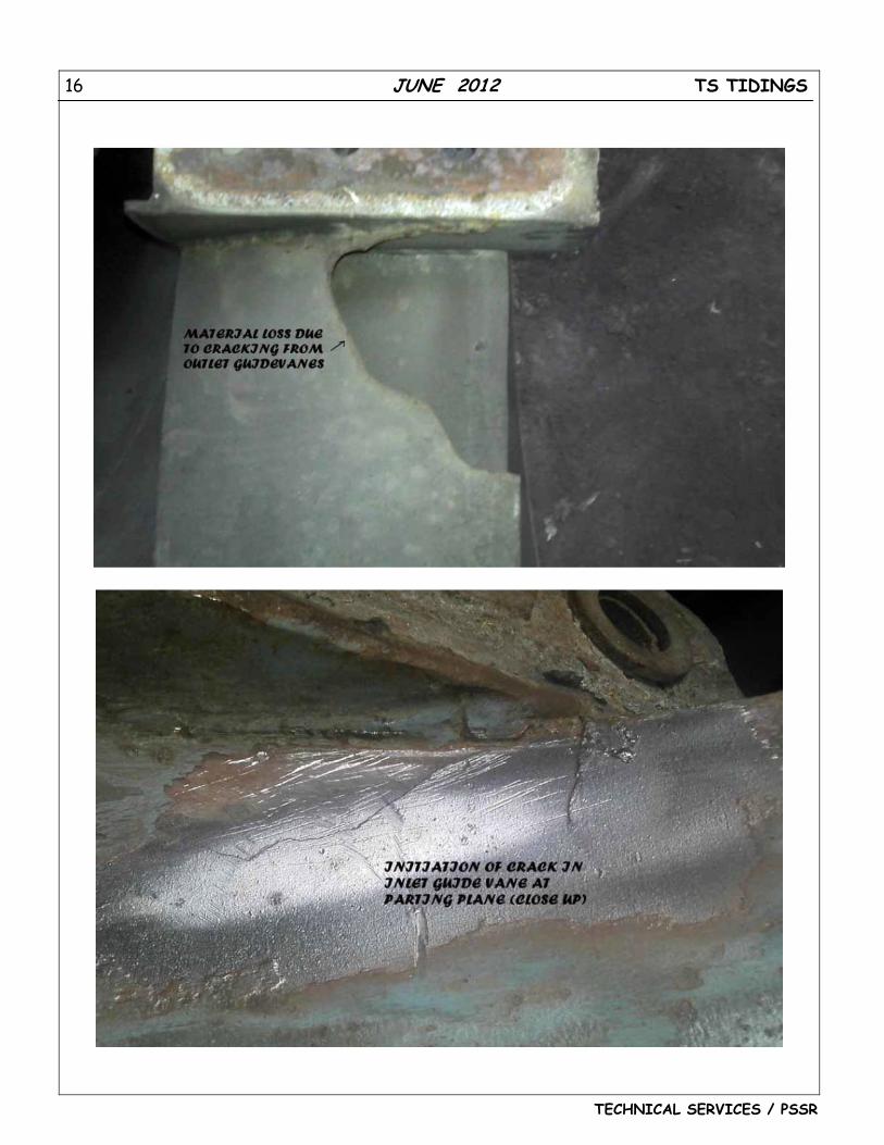
1. Second stage outlet guide vanes inlet side 25 Nos. blades & Outlet side 2 Nos. blades semi-circular portion to a diameter of about 70-100mm parent material got detached as shown in the photograph attached.
2. Crack in 2 no of vanes in OGV of stage-1 impeller. 3. 05 Nos. blade on 2nd stage impeller torn and 05 Nos. blade bent. 4. 04 Nos. blade on 1st stage impeller bent. 5. Oxides formed on all blades at various levels. 6. Blue paint on blades also got eroded at various levels. 7. PA Fan 3B housing was checked for bearing housing flange seating and found
OK.
BHEL/ Ranipet suggested:
1. Since most of the blades are damaged, PA Fan 3B OGV cannot be used as it is and hence it is to be replaced.
2. Damaged OGV may be sent to Ranipet for further investigations. 3. All the Fan blades to be thoroughly cleaned and check for any crack by DPT at
site. The results of DPT will be intimated to BHEL Ranipet.
13 JUNE 2012 TS TIDINGS
TECHNICAL SERVICES / PSSR
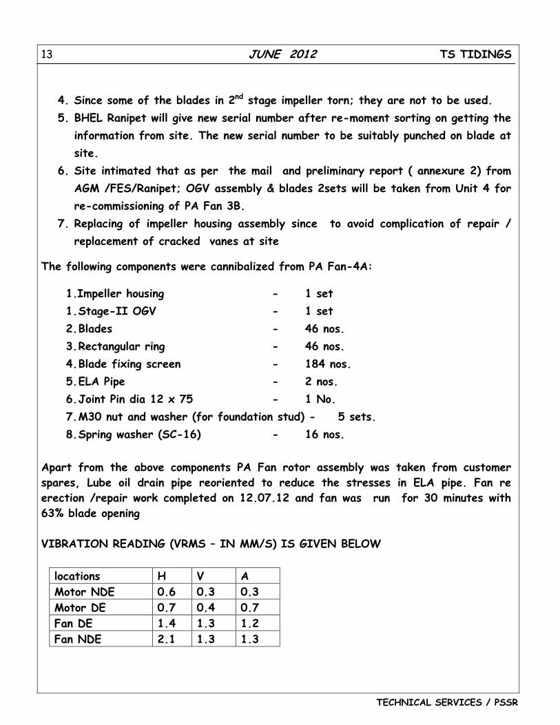
4. Since some of the blades in 2nd stage impeller torn; they are not to be used. 5. BHEL Ranipet will give new serial number after re-moment sorting on getting the
information from site. The new serial number to be suitably punched on blade at site.
6. Site intimated that as per the mail and preliminary report ( annexure 2) from AGM /FES/Ranipet; OGV assembly & blades 2sets will be taken from Unit 4 for re-commissioning of PA Fan 3B.
7. Replacing of impeller housing assembly since to avoid complication of repair / replacement of cracked vanes at site
The following components were cannibalized from PA Fan-4A:
1.Impeller housing - 1 set 1. Stage-II OGV - 1 set 2. Blades - 46 nos. 3. Rectangular ring - 46 nos. 4. Blade fixing screen - 184 nos. 5. ELA Pipe - 2 nos. 6. Joint Pin dia 12 x 75 - 1 No. 7. M30 nut and washer (for foundation stud) - 5 sets. 8. Spring washer (SC-16) - 16 nos.
Apart from the above components PA Fan rotor assembly was taken from customer spares, Lube oil drain pipe reoriented to reduce the stresses in ELA pipe. Fan re erection /repair work completed on 12.07.12 and fan was run for 30 minutes with 63% blade opening VIBRATION READING (VRMS – IN MM/S) IS GIVEN BELOW
locations H V A Motor NDE 0.6 0.3 0.3 Motor DE 0.7 0.4 0.7 Fan DE 1.4 1.3 1.2 Fan NDE 2.1 1.3 1.3
14 JUNE 2012 TS TIDINGS
TECHNICAL SERVICES / PSSR
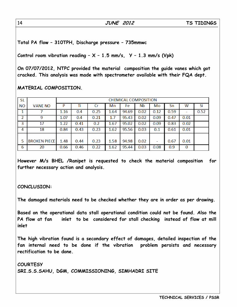
Total PA flow – 310TPH, Discharge pressure – 735mmwc Control room vibration reading – X – 1.5 mm/s, Y – 1.3 mm/s (Vpk) On 07/07/2012, NTPC provided the material composition the guide vanes which got cracked. This analysis was made with spectrometer available with their FQA dept. MATERIAL COMPOSITION.
However M/s BHEL /Ranipet is requested to check the material composition for further necessary action and analysis. CONCLUSION: The damaged materials need to be checked whether they are in order as per drawing. Based on the operational data stall operational condition could not be found. Also the PA flow at fan inlet to be considered for stall checking instead of flow at mill inlet The high vibration found is a secondary effect of damages, detailed inspection of the fan internal need to be done if the vibration problem persists and necessary rectification to be done. COURTESY SRI.S.S.SAHU, DGM, COMMISSIONING, SIMHADRI SITE
15 JUNE 2012 TS TIDINGS
TECHNICAL SERVICES / PSSR
PHOTOS
16 JUNE 2012 TS TIDINGS
TECHNICAL SERVICES / PSSR
17 JUNE 2012 TS TIDINGS
TECHNICAL SERVICES / PSSR
FEED BACK NO. 2
PROJECT: CHENNAI PETROLEUM CORPORATION LIMITED, GT 4, FRAME 5
PROBLEM: GT HYDRAULIC RATCHET TROUBLE ALARM DUE TO SLOW RATCHET CYCLE AND SUBSEQUENTLY IT FURTHER DETERIORATED LEADING TO STOPPING OF RATCHETING AND CLUTCH DISENGAGEMENT.
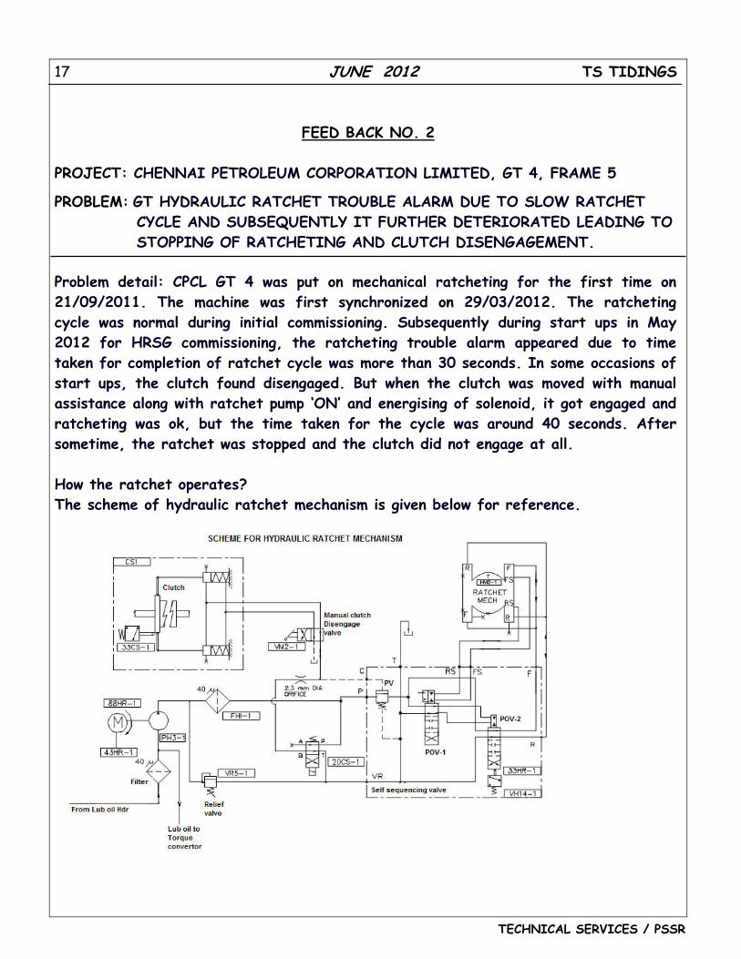
Problem detail: CPCL GT 4 was put on mechanical ratcheting for the first time on 21/09/2011. The machine was first synchronized on 29/03/2012. The ratcheting cycle was normal during initial commissioning. Subsequently during start ups in May 2012 for HRSG commissioning, the ratcheting trouble alarm appeared due to time taken for completion of ratchet cycle was more than 30 seconds. In some occasions of start ups, the clutch found disengaged. But when the clutch was moved with manual assistance along with ratchet pump ‘ON’ and energising of solenoid, it got engaged and ratcheting was ok, but the time taken for the cycle was around 40 seconds. After sometime, the ratchet was stopped and the clutch did not engage at all. How the ratchet operates? The scheme of hydraulic ratchet mechanism is given below for reference.
18 JUNE 2012 TS TIDINGS
TECHNICAL SERVICES / PSSR
The hydraulic ratchet consists of DC ratchet supply pump, hydraulic self sequencing valve assembly, torque converter mounted ratchet, starting clutch. The most important part of the ratchet mechanism is the hydraulic self sequencing assembly which controls the sequencing of the hydraulic ratchet. The self sequencing assembly consists of
1. Three way poppet solenoid valve (PV). 2. Four way fully pilot operated valve (POV-1). 3. Four way fully pilot operated valve with limit switch (POV-2).
The ratchet cycle starts with the ratchet timer L2HR going high. This in turn will energize the L20CSX (command to clutch solenoid) and L4HR (the master signal to the hydraulic ratchet motor). This starts the forward stroke in the ratchet cycle. The 20CS-1 solenoid is energized and ports oil to engage the clutch. Only after the clutch is engaged, pressure impulse will be build up to the poppet valve (PV) and this valve will allow oil to port to POV-1. The oil also ports to POV-2 causing the hydraulic ratchet to operate on forward stroke. This happens for about 12 sec.
Once the forward stroke is completed, the limit switch L33HRF goes high, signaling the end of the forward cycle. upon completion a port is opened inside the ratchet assembly which allows a pilot signal to shift POV-1. This causes a shift in POV-2 which will then port oil to the reverse stroke port.
The reverse stroke when completed a port opens inside the ratchet assembly allowing a pilot signal to shift POV-1 back to its original position. this in turn shifts the POV-2 back to its original position. This takes about 8-10 sec and the Limit switch 33HR-1 switches back to zero, Signifying the end of the reverse stroke and completion of the POV's returning to the initial position. This is when the Ratchet timer (3 min usually) is initiated.
Two sec after the 33HR-1 comes back to the initial 0 position, the clutch solenoid was deenergised and the hydraulic ratchet motor is stopped. This two second time delay insures that all the appropriate lines are full of oil for the next ratchet sequence. This cycle continues after 3 mins once again.
The suction and discharge lines of hydraulic ratchet pump is provided with filters of 40 microns brass filter elements. The differential pressure indication or the switch are not provided generally in this system. Also, there was no pressure gauge provided in the pump discharge for regular monitoring. The ratchet pump discharge pressure relief valve is provided, which is normally factory set (at 93 KSC).
19 JUNE 2012 TS TIDINGS
TECHNICAL SERVICES / PSSR
Analysis:
When the filter elements were cleaned, clutch engages and ratcheting occurs slowly. After few cycles, the clutch slowly disengages automatically.
The alignment of the jaw clutch and gap adjustments was checked as per product standard and adjusted. Even after adjustment, the behavior was same.
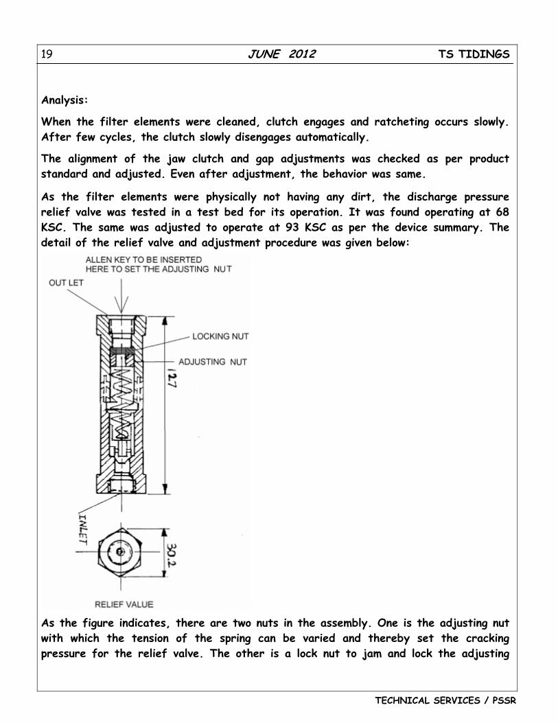
As the filter elements were physically not having any dirt, the discharge pressure relief valve was tested in a test bed for its operation. It was found operating at 68 KSC. The same was adjusted to operate at 93 KSC as per the device summary. The detail of the relief valve and adjustment procedure was given below:
As the figure indicates, there are two nuts in the assembly. One is the adjusting nut with which the tension of the spring can be varied and thereby set the cracking pressure for the relief valve. The other is a lock nut to jam and lock the adjusting
20 JUNE 2012 TS TIDINGS
TECHNICAL SERVICES / PSSR
nut at the desired setting. For adjusting the spring tension, the lock nut should be first loosened separated from the adjusting nut. (this done by limiting the Allen key depth to engage only the lock nut). Then for adjusting the spring tension the Allen key is to be inserted further in to engage both the nuts (now since the nuts are apart both nuts can be rotated to get the desired setting of the adjusting nut. Finally after the desired setting is achieved, the lock nut alone is to be tightened to jam with the set adjusting nut (this time again the Allen key is to be inserted to only engage the lock nut) so that the setting doesn’t get disturbed later.
Even after adjustment of the relief valve to the required value, the clutch did not engage. One pressure gauge was provided in the discharge of ratchet pump for observation during operation. The pressure developed was only around 40 ksc with clutch in engaged position manually and in disengaged position, the pressure developed was less than 10 ksc. It was suspected to be insufficient oil flow from the pump. It was decided to remove the filter element from pump suction filter temporarily for observation. On removing the filter element, the behaviour of ratchet cycle was normal and the cycle completed within 30 seconds as explained above. New filter was arranged from BHEL,Hyderabad and the ratchet problem was totally resolved.
Conclusion:
The root cause of the problem of slow ratcheting and disengagement was clogged filter in the suction of ratchet pump. These filters are brass filters and to be replaced on clogging. During commissioning, the timings of the forward, reverse stroke of the ratchet cycle is to be ensured for proper operation as per the scheme explained above. Any deviation to be rectified and the probable cause of defects in ratchet mechanism are:
1. Clogging of filters 2. Improper setting of pressure relief valve. 3. Improper setting of limit switches (Clutch engage/Forward stroke of sequencing
valve). 4. Solenoid valve malfunctioning like passing/jamming. 5. Failure of sealing rings in self sequencing valve. 6. Jaw clutch misalignment/ Jamming of clutch in spline shaft. 7. Logic mistakes in mark VI system. 8. Choking in oil ports/pipelines/orifice etc.,
Courtesy: Shri. M V Baskaran/DGM/Technical services, PSSR, Chennai
21 JUNE 2012 TS TIDINGS
TECHNICAL SERVICES / PSSR
CHEMICAL TREATMENT FOR SEA WATER USED AS COOLING MEDIUM
Sea water is used as cooling medium in condensers of power plants all over the word either in open cycle or closed cycle with cooling tower. In due course sea water usage will have biological growth in canal , pipelines , condensers and cooling towers which leads to blockage of flow path and poor heat transfer in condenser.
To avoid this biological growth different type of chemicals are dosed in the sea water
1. Chlorination
a. Gas chlorination b.Electro chlorination
2. Chlorine di oxide
3. Ozone
In TS tidings of June 2012, THEPROCESS GAS CHLORINATION is explained in detail. The other types dosing like ELECTROCHLORINATION, CHLORINE DIOXIDE and OZONE will be explained in the next issues of TS tidings
Use of chlorine for control of biological fouling in power plant cooling water system is the most effective way of controlling bio-fouling at reasonable concentration as chlorine is available at a low cost. Chlorine Gas feeders are simple and easy to control at low capital cost and requires minimum maintenance. The chlorine residual for shock dosing can be relatively short and in expensive. De-toxification (dechlorination) systems can be installed at a very nominal cost to meet the environmental requirement.
Total residual chlorine (TRC) as expressed in red book of United States of Environmental Protection Agency (EPA) specifies 0.2 mg/liters TRC. It should not exceed 160 minutes for 24 hours.
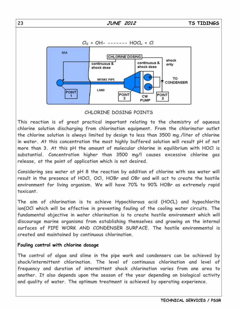
Point of chlorine dosing in Sea Water Normally the sea water for power plant is taken deep in the sea at Sea water intake head. The sea water travels through intake pipe and reaches the CW pump sump from where the water is pumped to the condenser.
22 JUNE 2012 TS TIDINGS
TECHNICAL SERVICES / PSSR
Continuous and Shock dosing chlorination
In Sea water application both continuous and shock dosing chlorination are applied for effective bio fouling.
Continuous chlorination At sea water intake head of inlet pipe, continuous dosing of approx. 1 - 2 ppm will be effective in control of Mollusks, algae, slime and weed. They constrict the flow of Sea water in the intake pipe. It also prevents sea shell deposition in the pipeline which is a most trouble-some to remove.
Continuous chlorine dosing is done near to the pump house ahead of bar racks and traveling water screen. 1-2 ppm is recommended so that the complete bar racks and traveling water screen can be kept clean and free from any bio fouling. This will also ensure the pump sump and pump suction side free from any slime growth. The free residual chlorine and the condenser outlet can be measured to determine the chlorine dosing as the chlorine demand of sea water varies according to the season and also the quality of the sea water.
Shock dosing chlorination - Dosing point No.3 Shock dosing of chlorination is done effectively at 1 - 5 ppm depending upon the quality of sea water. The recommended dosing time is one cycle time for every 8 hours shift which would be sufficient to keep the condenser cooling surface free from bio fouling and maintain the efficiency of the condenser and power generation.
Theory of Sea Water chlorination In Sea water at pH 7.4 - 8.1 less than 50% of chlorine is available as fast acting Hypochlorous acid. However Sea water also contains 60 mg/liter (ppm) bromide ion which displaces the chlorine, being a stronger oxidizing agent to produce hypobromous acid.
Cl2 + H20 --------- HOCL + H+ + Cl- HOCL + Br ---------- HOBr + Cl-
When chlorine is dissolved in water, it hydrolyzes rapidly according to the above equation. The rapidity of the reaction can be expressed that the chlorine molecule reacting with hydroxyl ion rather than with the water molecule.
23 JUNE 2012 TS TIDINGS
TECHNICAL SERVICES / PSSR
Cl2 + OH- ------- HOCL + Cl
CHLORINE DOSING POINTS
This reaction is of great practical important relating to the chemistry of aqueous chlorine solution discharging from chlorination equipment. From the chlorinator outlet the chlorine solution is always limited by design to less than 3500 mg./liter of chlorine in water. At this concentration the most highly buffered solution will result pH of not more than 3. At this pH the amount of molecular chlorine in equilibrium with HOCl is substantial. Concentration higher than 3500 mg/l causes excessive chlorine gas release, at the point of application which is not desired.
Considering sea water at pH 8 the reaction by addition of chlorine with sea water will result in the presence of HOCl, OCl, HOBr and OBr and will act to create the hostile environment for living organism. We will have 70% to 90% HOBr as extremely rapid toxicant.
The aim of chlorination is to achieve Hypochlorous acid (HOCL) and hypochlorite ion(OCl which will be effective in preventing fouling of the cooling water circuits. The fundamental objective in water chlorination is to create hostile environment which will discourage marine organisms from establishing themselves and growing on the internal surfaces of PIPE WORK AND CONDENSER SURFACE. The hostile environmental is created and maintained by continuous chlorination.
Fouling control with chlorine dosage
The control of algae and slime in the pipe work and condensers can be achieved by shock/intermittent chlorination. The level of continuous chlorination and level of frequency and duration of intermittent shock chlorination varies from one area to another. It also depends upon the season of the year depending on biological activity and quality of water. The optimum treatment is achieved by operating experience.
24 JUNE 2012 TS TIDINGS
TECHNICAL SERVICES / PSSR
Continuous chlorination dosing level is in the region of 0.3-2 ppm. Shock chlorination dosing level is practiced at 2-5 ppm for 1 cycle time for every 4-8 hours. The practice with natural sea water chlorination is to monitor the total 30 minutes demand. The water is dosed with certain quantity of equivalent chlorine. The residual is measured after 30 minutes. The difference between the initial dose level and the residual level is reported as the chlorine demand. Only shock dosing chlorination is not sufficient for effectively treating the sea water in some areas. When shell forming organisms grow in the water, they attach themselves to the piping. Even if the organism is killed by Shock chlorination, the dead remains attached to the piping and subsequently can break free and clog the piping with disastrous results. Continuous chlorination prevents settlement and growth of marine organisms. Various tests conducted indicates residual of 0.1 mg/litter will prevent the growth of marine organisms.
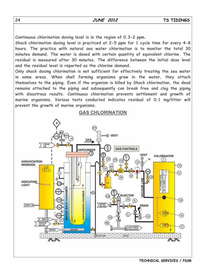
GAS CHLORINATION
25 JUNE 2012 TS TIDINGS
TECHNICAL SERVICES / PSSR
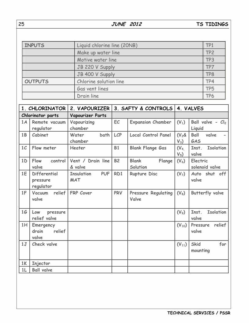
INPUTS Liquid chlorine line (20NB) TP1 Make up water line TP2 Motive water line TP3 JB 220 V Supply TP7 JB 400 V Supply TP8 OUTPUTS Chlorine solution line TP4 Gas vent lines TP5 Drain line TP6
1. CHLORINATOR 2. VAPOURIZER 3. SAFTY & CONTROLS 4. VALVES Chlorinator parts Vapourizer Parts 1A Remote vacuum
regulator Vapourizing chamber
EC Expansion Chamber (V1) Ball valve - Cl2 Liquid
1B Cabinet Water bath chamber
LCP Local Control Panel (V2& V3)
Ball valve - GAS
1C Flow meter Heater B1 Blank Flange Gas (V4,
V5) Inst. Isolation valve
1D Flow control valve
Vent / Drain line & valve
B2 Blank Flange Solution
(V6) Electric solenoid valve
1E Differential pressure regulator
Insulation PUF MAT
RD1 Rupture Disc (V7) Auto shut off valve
1F Vacuum relief valve
FRP Cover PRV Pressure Regulating Valve
(V8) Butterfly valve
1G Low pressure relief valve
(V9) Inst. Isolation valve
1H Emergency drain relief valve
(V10) Pressure relief valve
1J Check valve (V11) Skid for mounting
1K Injector 1L Ball valve
26 JUNE 2012 TS TIDINGS
TECHNICAL SERVICES / PSSR
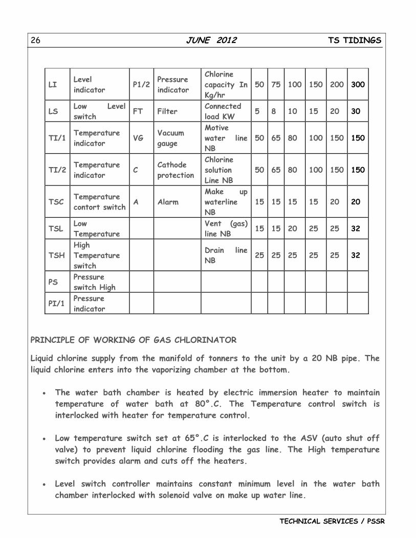
LI Level indicator
P1/2 Pressure indicator
Chlorine capacity In Kg/hr
50 75 100 150 200 300
LS Low Level switch FT Filter
Connected load KW 5 8 10 15 20 30
TI/1 Temperature indicator VG
Vacuum gauge
Motive water line NB
50 65 80 100 150 150
TI/2 Temperature indicator C
Cathode protection
Chlorine solution Line NB
50 65 80 100 150 150
TSC Temperature contort switch A Alarm
Make up waterline NB
15 15 15 15 20 20
TSL Low Temperature
Vent (gas) line NB 15 15 20 25 25 32
TSH High Temperature switch
Drain line NB 25 25 25 25 25 32
PS Pressure switch High
PI/1 Pressure indicator
PRINCIPLE OF WORKING OF GAS CHLORINATOR
Liquid chlorine supply from the manifold of tonners to the unit by a 20 NB pipe. The liquid chlorine enters into the vaporizing chamber at the bottom.
• The water bath chamber is heated by electric immersion heater to maintain temperature of water bath at 80°.C. The Temperature control switch is interlocked with heater for temperature control.
• Low temperature switch set at 65°.C is interlocked to the ASV (auto shut off valve) to prevent liquid chlorine flooding the gas line. The High temperature switch provides alarm and cuts off the heaters.
• Level switch controller maintains constant minimum level in the water bath chamber interlocked with solenoid valve on make up water line.
27 JUNE 2012 TS TIDINGS
TECHNICAL SERVICES / PSSR
• The expansion chamber and liquid chlorine line with a rupture disc and pressure switch assembly protects the line from rupture due to the thermal expansion of locked liquid chlorine in the pipeline. The pressure switch provides alarm.
• Local control panel of vapourizer provides required interlocks indicating lamp and annunciation for high & low temperature of water bath, low level in water bath & high pressure in liquid line.
• The pressure relief valve is provided as safety valve. The filter is provided to eradicate solid impurities. Pressure regulating valve reduces the chlorine gas pressure from 8 Kg/cm2 normal inlet pressure to 2.5 Kg/cm2. on the downstream of PRV
• The chlorinator part - Vacuum regulator is normally closed and opens only in case of sufficient vacuum present. The vacuum in chlorinator is created by a motive water supply operated injector. The vacuum from the injector extends through the vacuum line up to the vacuum regulator. The flow meter of chlorinator is calibrated in Kg/hr. of chlorine.
• The flow control valve on the chlorinator is for manual setting of required flow in the chlorinator. The Differential pressure regulator maintains a constant differential pressure across the flow control valve. The Vacuum relief valve is to maintain maximum vacuum in the system. If the vacuum exceeds it takes atmospheric air inside for vacuum reduction.
• The emergency drain relief valve is vacuum to close and will open any water accumulation in the line more than 300 mm WC. The check valve prevents water entering.
• The chlorine solution line is taken to the point of application through a diffuser.
The entire unit is skid mounted with pre-fabricated pipelines with all interconnecting fittings as shown in the scheme.
28 JUNE 2012 TS TIDINGS
TECHNICAL SERVICES / PSSR
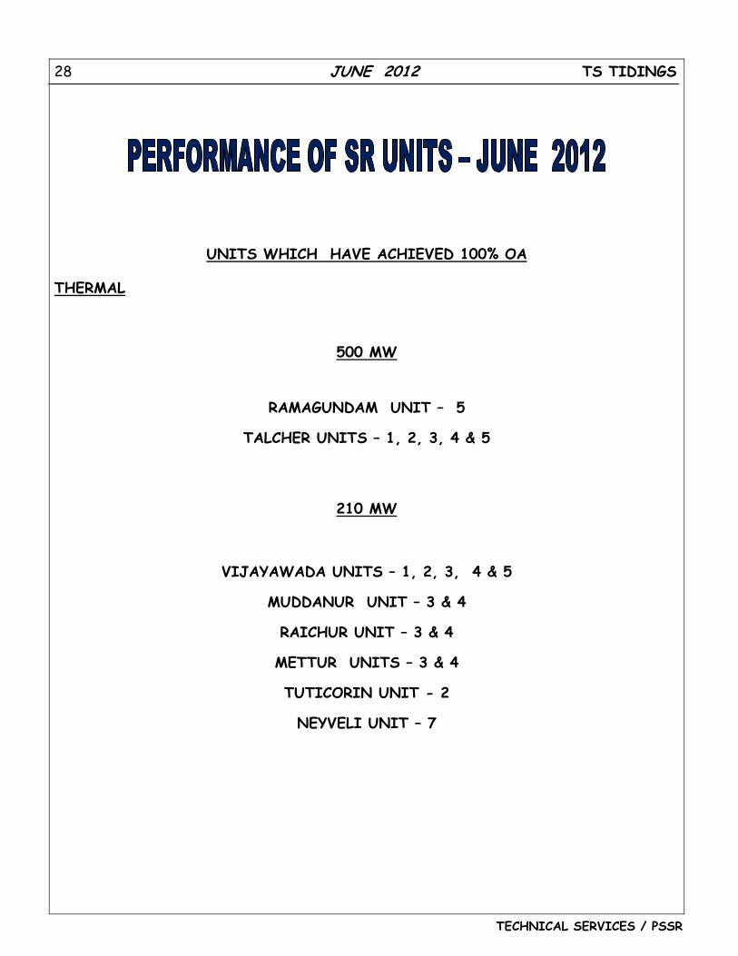
UNITS WHICH HAVE ACHIEVED 100% OA
THERMAL
500 MW
RAMAGUNDAM UNIT – 5
TALCHER UNITS – 1, 2, 3, 4 & 5
210 MW
VIJAYAWADA UNITS – 1, 2, 3, 4 & 5
MUDDANUR UNIT – 3 & 4
RAICHUR UNIT – 3 & 4
METTUR UNITS – 3 & 4
TUTICORIN UNIT - 2
NEYVELI UNIT – 7
29 JUNE 2012 TS TIDINGS
TECHNICAL SERVICES / PSSR
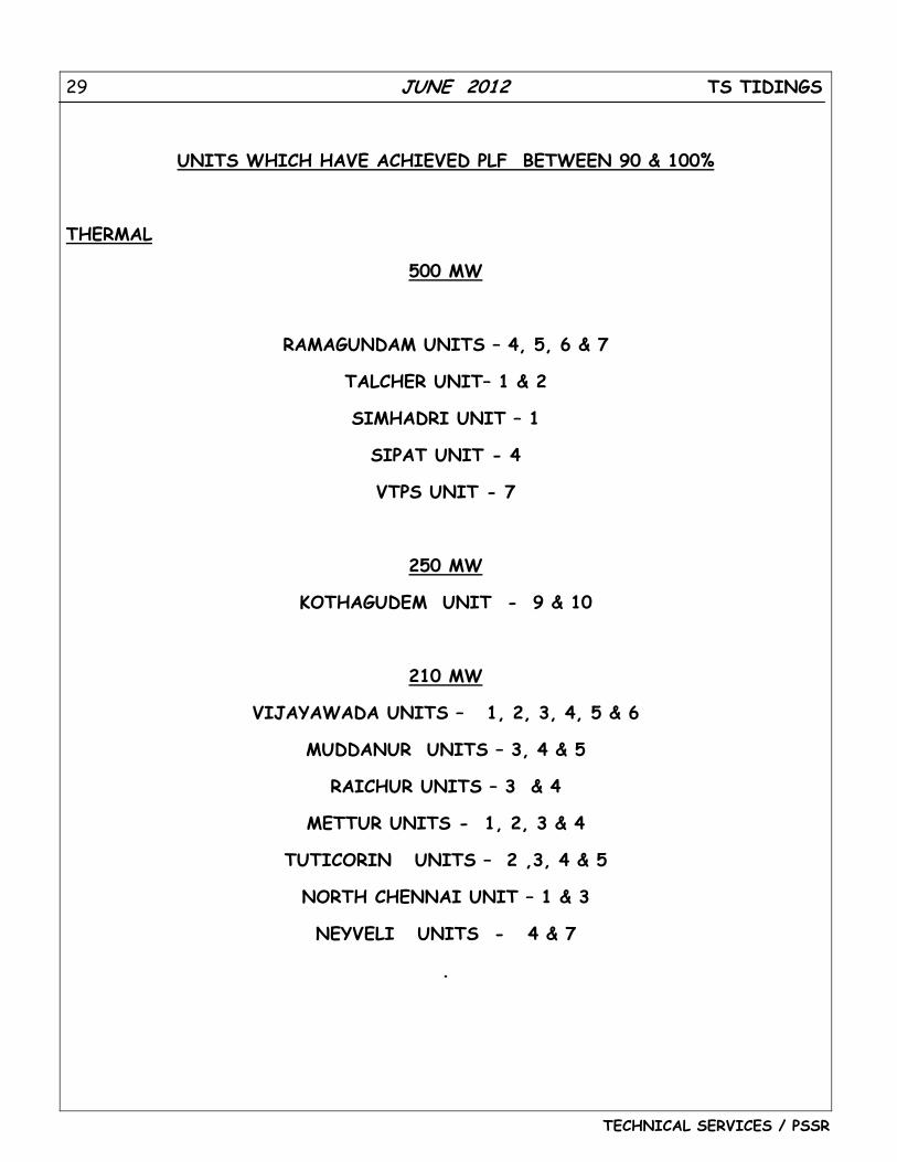
UNITS WHICH HAVE ACHIEVED PLF BETWEEN 90 & 100%
THERMAL
500 MW
RAMAGUNDAM UNITS – 4, 5, 6 & 7
TALCHER UNIT– 1 & 2
SIMHADRI UNIT – 1
SIPAT UNIT - 4
VTPS UNIT - 7
250 MW
KOTHAGUDEM UNIT - 9 & 10
210 MW
VIJAYAWADA UNITS – 1, 2, 3, 4, 5 & 6
MUDDANUR UNITS – 3, 4 & 5
RAICHUR UNITS – 3 & 4
METTUR UNITS - 1, 2, 3 & 4
TUTICORIN UNITS – 2 ,3, 4 & 5
NORTH CHENNAI UNIT – 1 & 3
NEYVELI UNITS - 4 & 7
.
30 JUNE 2012 TS TIDINGS
TECHNICAL SERVICES / PSSR
0.00
20.00
40.00
60.00
80.00
100.00
120.00
North
Che
nnai
Neyve
li
Raich
ur
Tutic
orin
Ram
agun
dam
Mud
danu
r
Koth
agud
am
Vija
yawad
a
VTPS
‐ 7
Met
tur
Talch
er
Simha
dri
Sipat
Amar
kant
ak
Bella
ry‐1
2011‐12 2012‐13
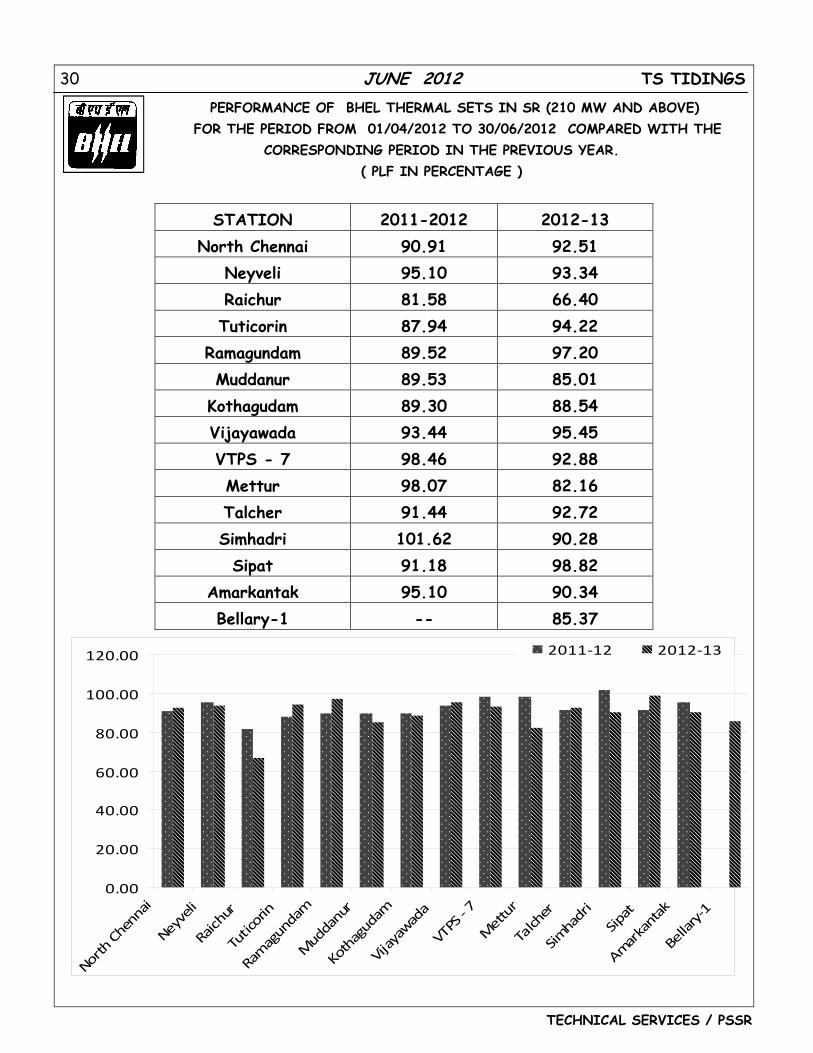
PERFORMANCE OF BHEL THERMAL SETS IN SR (210 MW AND ABOVE) FOR THE PERIOD FROM 01/04/2012 TO 30/06/2012 COMPARED WITH THE
CORRESPONDING PERIOD IN THE PREVIOUS YEAR. ( PLF IN PERCENTAGE )
STATION 2011-2012 2012-13 North Chennai 90.91 92.51
Neyveli 95.10 93.34 Raichur 81.58 66.40 Tuticorin 87.94 94.22
Ramagundam 89.52 97.20 Muddanur 89.53 85.01
Kothagudam 89.30 88.54 Vijayawada 93.44 95.45 VTPS - 7 98.46 92.88 Mettur 98.07 82.16 Talcher 91.44 92.72 Simhadri 101.62 90.28 Sipat 91.18 98.82
Amarkantak 95.10 90.34 Bellary-1 -- 85.37


