
Sate
llite
Tel
evis
ion
KVHT
racV
ision
®
L2/S
2
owner’smanual
• Installation Instructions • User’s Guide• Technical Manual
A Guide to TracVision L2/S2

154-0195 Addendum to Rev. C
TracVision L2/S2 Owner’sManual Addendum(ECO # 6857)The following information applies to Revision C of the TracVision L2/S2 Owner’s Manual (KVH Part Number 54-0195).
The DISH 500 mode, in which the SAT SELECT button switchesbetween the two DISH 500 satellites, has been changed to make it easierto use. The following instructions have been updated to reflect thischange.
3.5 DISH 500 OperationThe DISH 500 service offers programming on two differentsatellites (Echo 119 and 110). To easily switch between these twosatellites, you will need to configure the system for DISH 500mode, in which the SAT SELECT button selects between just theEcho 119 and 110 satellites.
3.5.1 Configuring the System for DISH 500 Mode
To configure the TracVision system for DISH 500, follow the stepsbelow.
1. Turn on your receiver, TV, and TracVision system.
2. Using the receiver’s remote control, go to the“Point Dish/Signal Strength” screen (press MENU,6, 1, 1 (on most models)) and select satellite 119 andtransponder 11.
3. When the switchplate’s Status indicator fullyilluminates (stops flashing), check the signalstrength meter on the TV. If the meter turns greenand indicates “Locked–Echostar 119,” skip to step 6.
N E T W O R K
254-0195 Addendum to Rev. C
4. Press the switchplate’s SAT SELECT button for 1 second. When you release the button, the Statusindicator starts flashing while the antenna searchesfor another satellite.
5. When the switchplate’s Status indicator fullyilluminates again, check the signal strength meter. If the meter turns green and indicates “Locked–Echostar 119,” proceed to step 6. If the meter staysred, repeat step 4.
6. Press and hold the SAT SELECT button until theStatus indicator flashes quickly five times(approximately 5 seconds).
3.5.2 Switching Between DISH 500 SatellitesOnce the system is configured for DISH 500 mode, you can easilyswitch between the 119 and 110 satellites. Simply press the SATSELECT button to switch from one to the other.
IMPORTANT! Switch between satellites only while thevehicle is stationary or, if your system is a TracVision L2, whileyou are driving in a straight line. If you try to switch satelliteswhile the vehicle is turning, the antenna may lock onto thewrong satellite. If this occurs, you will need to reset the system tothe factory default (as described in the next section) then reconfigurethe system for DISH 500 mode (as described in the previous section).
3.5.3 Resetting the System to Factory DefaultTo reset the system to the factory default, in which the antennasearches for a different satellite whenever the SAT SELECTbutton is pressed, follow the steps below.
1. Turn off the TracVision system.
2. Press and hold the SAT SELECT button as youturn on the TracVision system.
3. Continue holding down the SAT SELECT buttonuntil the Status indicator flashes quickly five times(approximately 5 seconds). When you release theSAT SELECT button, the antenna starts up in thefactory default mode.
If you turn off the TracVisionsystem, move the vehicle, then turnthe system back on, the antennamay not be able to find the correctsatellite upon startup. In this case,you will need to reset the system tothe factory default and thenreconfigure the system for DISH 500 mode.
Congratulations!You have selected one of the most advanced land-mobile satellitetracking systems available today. KVH® Industries’ TracVision® L2/S2 is designed for use with DIRECTV®, DISHNetwork™, and ExpressVu. This manual provides detailedinstructions on the proper installation, use, and maintenance ofyour TracVision L2/S2 system. Before using this manual, besure to check the inside back cover for any addenda, whichmay detail changes to the manual’s information.
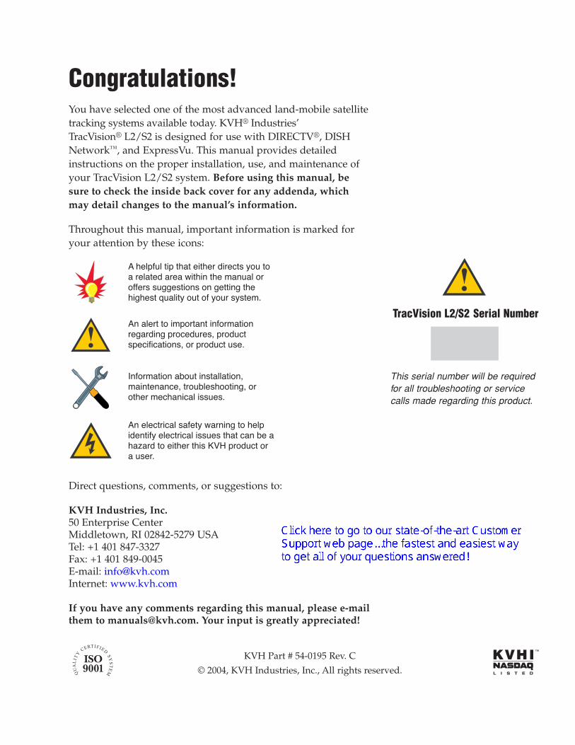
Throughout this manual, important information is marked foryour attention by these icons:
Direct questions, comments, or suggestions to:
KVH Industries, Inc.50 Enterprise CenterMiddletown, RI 02842-5279 USATel: +1 401 847-3327Fax: +1 401 849-0045E-mail: [email protected]: www.kvh.com
If you have any comments regarding this manual, please e-mailthem to [email protected]. Your input is greatly appreciated!
� ������� �� ��� ����� ��� �� ��� �� ������ �� ���� ��� ���� �������� ���������� �� ������ ��������� ����� ��� �� ���� �������
�� ���� �� ������� ��������������� ��� ������� ����� ���� � ����� �� ����� � ����
�� ��� �� � ����� ����� �� ���������� ��� �� � ����� ��� � �� ���� �� ����� ��� ��� ����� � �� �����
��������� ���� ��������������� �� ��������������� ������� �� �� � ������
TracVision L2/S2 Serial Number
This serial number will be requiredfor all troubleshooting or servicecalls made regarding this product.
KVH Part # 54-0195 Rev. C
© 2004, KVH Industries, Inc., All rights reserved.

TracVision® and KVH® are registered trademarks of KVH Industries, Inc.
DIRECTV® is an official trademark of DIRECTV, a unit of GM Hughes Electronics Corporation.
DISH Network™ is an official trademark of EchoStar Communications Corporation.
ExpressVu is a property of Bell ExpressVu, a wholly owned subsidiary of Bell Satellite Services.
Table of Contents1 Introduction . . . . . . . . . . . . . . . . . . . . . . . . . . . . . . . . .1-11.1 Digital Satellite Television . . . . . . . . . . . . . . . . . . . . . . . . . . . . . . .1-1
1.2 System Overview . . . . . . . . . . . . . . . . . . . . . . . . . . . . . . . . . . . . . .1-1
1.2.1 TracVision L2/S2 Components ...............................................1-2
1.2.2 Integrated Receiver/Decoder (IRD) ........................................1-2
1.3 Materials Provided with TracVision L2/S2 . . . . . . . . . . . . . . . . . .1-2
1.3.1 Additional Materials Required for TracVision L2/S2 Use........1-3
2 Installation . . . . . . . . . . . . . . . . . . . . . . . . . . . . . . . . .2-12.1 Choosing the Best Location . . . . . . . . . . . . . . . . . . . . . . . . . . . . .2-3
2.2 Mounting the Antenna Unit . . . . . . . . . . . . . . . . . . . . . . . . . . . . . .2-4
2.3 Connecting System Components . . . . . . . . . . . . . . . . . . . . . . . . .2-9
2.3.1 Connecting the Antenna to the Switchplate .........................2-10
2.3.2 Connecting the Antenna to the IRD .....................................2-10
2.3.3 Sealing the Cable Access Hole ............................................2-12
2.3.4 Connecting the Switchplate to the IRD ................................2-12
2.3.5 Connecting the Switchplate to Vehicle Power ......................2-13
2.3.6 Connecting the IRD Ground Wire.........................................2-13
2.3.7 Installing the Switchplate ......................................................2-13
2.4 Activating the IRD . . . . . . . . . . . . . . . . . . . . . . . . . . . . . . . . . . . . .2-14
2.5 Checking Out the System . . . . . . . . . . . . . . . . . . . . . . . . . . . . . .2-14
2.5.1 Checking Out the System Usingan IRD Data Connection ......................................................2-14
2.5.2 Checking Out the System Withoutan IRD Data Connection ......................................................2-16
2.6 Configuring TracVision L2/S2 for Remote Satellite Dish Operation . . . . . . . . . . . . . . . . . . . . . . . . . . . . . . . .2-17
3 Using Your TracVision L2/S2 . . . . . . . . . . . . . . . . . . . . . .3-13.1 Turning On the System . . . . . . . . . . . . . . . . . . . . . . . . . . . . . . . . .3-1
3.2 Tracking the Correct Satellite . . . . . . . . . . . . . . . . . . . . . . . . . . . .3-3
i54-0195 Rev. C
3.2.1 Using the IRD for Satellite Selection ......................................3-3
3.2.2 Using the Switchplate for Satellite Selection..........................3-3
3.2.2.1 The Status Indicator . . . . . . . . . . . . . . . . . . . . . . . . . . . . .3-4
3.3 Turning Off the System . . . . . . . . . . . . . . . . . . . . . . . . . . . . . . . . .3-4
3.4 Watching Television . . . . . . . . . . . . . . . . . . . . . . . . . . . . . . . . . . . .3-4
3.5 DISH 500 Operation . . . . . . . . . . . . . . . . . . . . . . . . . . . . . . . . . . . .3-5
3.5.1 Configuring the System for DISH 500 Mode ..........................3-5
3.5.2 Switching Between DISH 500 Satellites.................................3-6
3.5.3 Resetting the System to Factory Default................................3-6
4 Troubleshooting . . . . . . . . . . . . . . . . . . . . . . . . . . . . . .4-14.1 Causes and Remedies for Common Operational Issues . . . . . .4-1
4.1.1 Blown Fuse or Improper Wiring..............................................4-2
4.1.2 Dew or Rain Pooling on Dome ...............................................4-2
4.1.3 Satellite Signal Blocked ..........................................................4-2
4.1.4 Satellite Coverage Issue.........................................................4-3
4.1.5 Vehicle Turning During Startup (TracVision L2 only) ..............4-3
4.1.6 Incorrect or Loose RF Connectors .........................................4-3
4.1.7 Type of Multiswitch Used ........................................................4-3
4.1.8 Stationary Use Only (TracVision S2 only) ..............................4-3
4.2 IRD Troubleshooting . . . . . . . . . . . . . . . . . . . . . . . . . . . . . . . . . . . .4-4
4.2.1 IRD Wiring ..............................................................................4-4
4.2.2 AC Power Fluctuating .............................................................4-4
4.2.3 No IRD Data Connection........................................................4-4
4.2.4 EchoStar IRD Activation Check..............................................4-4
4.2.5 Failed IRD Status Check ........................................................4-5
4.2.6 IRD Faulty...............................................................................4-5
4.3 Antenna Gyro and LNB Faults . . . . . . . . . . . . . . . . . . . . . . . . . . . .4-6
4.4 Computer Diagnostics . . . . . . . . . . . . . . . . . . . . . . . . . . . . . . . . . .4-6
4.5 Maintenance Port Parser Commands . . . . . . . . . . . . . . . . . . . . . .4-7
ii

5 Maintenance . . . . . . . . . . . . . . . . . . . . . . . . . . . . . . . .5-15.1 Warranty/Service Information . . . . . . . . . . . . . . . . . . . . . . . . . . . .5-1
5.2 Preventive Maintenance . . . . . . . . . . . . . . . . . . . . . . . . . . . . . . . . .5-1
5.3 Replaceable Parts . . . . . . . . . . . . . . . . . . . . . . . . . . . . . . . . . . . . . .5-2
5.4 Field Replaceable Unit Procedures . . . . . . . . . . . . . . . . . . . . . . . .5-3
5.4.1 PCB Removal and Replacement............................................5-5
5.4.2 Antenna Gyro Assembly (TracVision L2 only) ........................5-6
5.4.3 Antenna LNB Replacement ....................................................5-8
5.5 Preparation for Shipment . . . . . . . . . . . . . . . . . . . . . . . . . . . . . . .5-10
Appendix A System Specifications
Appendix B Comprehensive System Wiring Diagram
Appendix C Switchplate Template
Appendix D EchoStar IRD Activation Procedure
Appendix E Startup Data Sequences
Appendix F Maintenance Port Parser Commands
iii54-0195 Rev. C

1 Introduction1.1 Digital Satellite TelevisionDIRECTV®, DISH Network™, and ExpressVu systems transmitdigital audio and video data from land-based transmitters to asatellite “parked” above the equator. Each satellite relays thesignals in spot beams covering the continental United States.TracVision L2/S2 automatically identifies, locks onto, andreceives signals from the appropriate satellite. TracVision S2 isdesigned for stationary use only; TracVision L2 works while yourvehicle is at rest and in motion.
1.2 System OverviewA complete satellite TV system includes the TracVision L2/S2connected to an integrated receiver/decoder (IRD) and atelevision set. A desktop or laptop computer is used to conductdiagnostics. The complete system is illustrated in Figure 1-1.System specifications and a wiring diagram are provided inAppendices A and B, respectively.
1-1
Introduction
54-0195 Rev. C
11-16 Volts DC2.5-3.5 Amps
Satellite Receiver 1
RF2
Options Purchased Separately
TV 1
Data/Power
VehiclePower
Switchplate
PC Maintenance
Satellite Receiver 2TV 2 Laptop PC
TracVision Antenna
RF1
Data (optional)
Baseplate
Radome
Figure 1-1TracVision L2/S2 SystemConfiguration
KVH offers an upgrade kit (KVHPart #02-1026) that adds in-motiontracking capability to the TracVision S2, allowing you toreceive satellite signals while onthe move.

1-2
1.2.1 TracVision L2/S2 ComponentsThe antenna unit includes the antenna positioning mechanism,signal front end, power supply and control elements. Theantenna is a parabolic dish mounting a dual-output low noiseblock (LNB) converter with built-in preamplifier. A molded ABSradome encloses the baseplate and is secured in place withstandard fasteners. Connectors on the back of the baseplate jointhe power, signal, and control cabling from units inside thevehicle.
1.2.2 Integrated Receiver/Decoder (IRD)The IRD (purchased separately) receives satellite signals from theantenna unit for signal decoding, processing, and channelselection, and sends the signals to the TV set for viewing. Inaddition, messages can be sent from the IRD to the antenna unitand messages can be received from the antenna unit for displayon the television screen. The IRD also provides the interface forthe user to activate authorization for reception. Please refer to theUser’s Manual provided with your selected IRD for completeoperating instructions.
1.3 Materials Provided withTracVision L2/S2
Table 1-1 lists the units, cables, and materials packed in theTracVision L2/S2 package by name and KVH part number.
Component KVH Part No.
Antenna Unit (TracVision L2) 01-0225-16
Antenna Unit (TracVision S2) 01-0225-17
RF Cable (28 ft) 32-0417-28
Data/Power Cable (28 ft) 32-0730-28
IRD Ground Wire (50 ft) 32-0583-50
Kitpack* 72-0125
Installation and Operation Manual 54-0195
* A complete listing of kitpack contents is provided in Table 2-2.
A Guide to TracVision L2/S2
On-screen messages are notavailable with a DISH Network IRD.
Table 1-1TracVision L2/S2 Packing List
Cables for the TracVision L2/S2 arestored beneath the antenna unitduring shipping.
Before you can start watchingsatellite TV using your TracVisionantenna, you will need to activateyour IRD. Refer to Section 2.4,“Activating the IRD,” for moredetails.

1.3.1 Additional Materials Required forTracVision L2/S2 Use
To make full use of your new TracVision L2/S2 and receivesatellite TV, you will need to provide/purchase the following:
• Television
• Appropriate IRD for your selected satellite TV service
1-3
Introduction
54-0195 Rev. C
You can purchase and/or activatean IRD directly from KVH! Call KVHat 1-888-584-4163 for details.

2-1
Installation
54-0195 Rev. C
2 InstallationTracVision L2/S2 is designed for simple installation and setup.Just follow these easy steps:
Step Refer to Section...
1. Choose the antenna location 2.1
2. Mount the antenna unit 2.2
3. Connect the system components 2.3
4. Activate the IRD 2.4
5. Check out the system 2.5
Tools and Materials Required• Electric drill
• 3⁄16"-drill bit and 3⁄4" hole saw and auger bit
• #2 Phillips and #0 flat tip screwdrivers
• RG-6 or RG-11 (75 ohms) RF cable (if installingtwo RF cables - refer to Section 2.3.2 for details)
• Silicone sealant or RTV
• 7⁄16"-open end wrench
• Adhesive suitable for specific roof constructionand materials (e.g., Liquid Nails)
• Rivet gun and 3⁄16"-rivets (or other fastener suitablefor specific roof construction)
• (Recommended) PC with terminal emulationsoftware, such as Windows Hyperterminal orPROCOMM, and a DB9 (male-to-female) PC datacable
Plan the entire installation beforeproceeding! Take into accountcomponent placement, cablerunning distances between units,and accessibility to the equipmentafter installation.
While some DIRECTV IRDs offer on-screen messages, it isrecommended that a PC beavailable for all installations of DIRECTV, EchoStar, andExpressVu.
Table 2-1Installation Process

2-2
A Guide to TracVision L2/S2
Kitpack Contents
Table 2-2 lists the materials provided in the kitpack.
Part Qty. KVH Part No.
Switchplate Assembly 1 02-1236-01
Tie-wraps 5 22-0013
RJ11 Handset Cable 1 32-0724-25
Clam Shell Ventilator 1 19-0230
#6 x 3⁄4" Thread-forming Screws 5 14-0298-12
1⁄4"-20 x 5⁄8" Hex Screws 4 14-0250-10
1⁄4" Flat Washers 4 14-0251
3⁄8" Hole Plugs 2 19-0282-06
Table 2-2Kitpack Contents

2-3
Installation
54-0195 Rev. C
2.1 Choosing the Best Location• Since the TracVision antenna requires a clear view
of the southern sky to receive satellite signals, theideal antenna site has an unobstructed view of thehorizon/satellite all around.
• Keep the antenna clear of any obstructions on theroof (e.g., air conditioners). The antenna requires a15º to 75º look angle to receive satellite signals.
• Consider the location of the antenna relative to thelocation of any equipment or necessary wiringwithin the vehicle.
• Be sure to mount the antenna on a horizontalsurface with a minimum roof (or other mountingsurface) radius of 250". In other words, whenplaced flat on the mounting surface, the mountingplates should be less than 7⁄16" above the mountingsurface (see Figure 2-2). Any larger gap will warpthe baseplate and seriously damage the antenna.
Blocked! TracVision Antenna
Air Conditioner
Vehicle Roof
Figure 2-1Antenna Blockage
" Maximum Gap716
Figure 2-2Maximum Mounting Surface Slope
2-4
A Guide to TracVision L2/S2
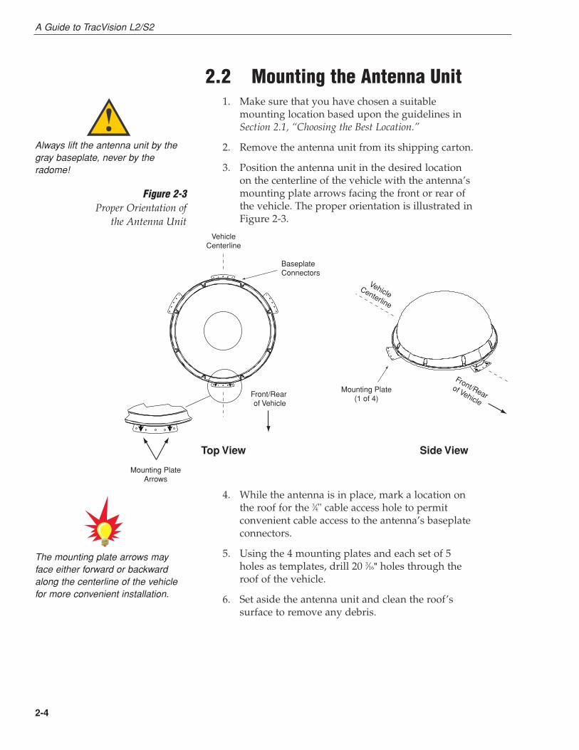
2.2 Mounting the Antenna Unit1. Make sure that you have chosen a suitable
mounting location based upon the guidelines inSection 2.1, “Choosing the Best Location.”
2. Remove the antenna unit from its shipping carton.
3. Position the antenna unit in the desired locationon the centerline of the vehicle with the antenna’smounting plate arrows facing the front or rear ofthe vehicle. The proper orientation is illustrated inFigure 2-3.
4. While the antenna is in place, mark a location onthe roof for the 3⁄4" cable access hole to permitconvenient cable access to the antenna’s baseplateconnectors.
5. Using the 4 mounting plates and each set of 5holes as templates, drill 20 3⁄16" holes through theroof of the vehicle.
6. Set aside the antenna unit and clean the roof’ssurface to remove any debris.
VehicleCenterline
VehicleCenterline
Front/Rear of Vehicle
Front/Rearof Vehicle
Top View Side View
Mounting Plate(1 of 4)
BaseplateConnectors
Mounting PlateArrows
Always lift the antenna unit by thegray baseplate, never by theradome!
The mounting plate arrows mayface either forward or backwardalong the centerline of the vehiclefor more convenient installation.
Figure 2-3Proper Orientation of
the Antenna Unit

2-5
Installation
54-0195 Rev. C
7. Seal the two baseplate holes shown in Figure 2-4with the plugs provided in the kitpack.
8. Apply construction adhesive to the bottom of theantenna’s four mounting plates. If using a liquidconstruction adhesive, apply beads to themounting plates in a zig-zag pattern.
9. Reposition the antenna, lining up the mountingplate holes with the holes in the roof. Attach themounting plates to the roof using 3⁄16"-diameterrivets (or appropriate fasteners). Seal all rivetheads and edges with silicone.
10. Remove and save the 8 pan head screws and flatwashers that secure the radome to the baseplate.Carefully lift the radome straight up until clear ofthe antenna assembly and set aside.
11. When the antenna unit is installed with thebaseplate connectors facing the rear of the vehicle,the drain holes are located as shown in Figure 2-5.
Factory-drilledDrain Hole Positions
Front ofVehicle
Figure 2-5Baseplate Connectors Facing Rear of Vehicle – Factory-drilledDrain Hole Locations
If the roof’s mounting surface is notperfectly flat as KVH recommends,make sure the baseplate does notwarp when you attach theantenna’s mounting plates. Refer toSection 2.1, “Choosing the BestLocation,” for further details.
Figure 2-4Antenna Baseplate (Bottom View)
Baseplate Holes

2-6
A Guide to TracVision L2/S2
12. Cut the tie-wraps holding the antenna unit to theforward shipping restraint (see Figure 2-7).
� ������� ���
� ����� ��� ���
������ ��������
������ ��������
��� ��� �����
Figure 2-7Forward Shipping Restraint
(Arranged for Shipping)
Recommended3/16" Drain Hole
Positions
Drain Hole Angle(relative to baseplate)
Front ofVehicle
Angle of Hole, relative to front
Angle of Hole, relative to front
Figure 2-6Baseplate Connectors Facing Front
of Vehicle – Recommended Drain Hole Locations
You MUST drill out the drain holesas indicated to ensure that anymoisture that enters the baseplateis able to drain. Ensure that factory-drilled holes are completely sealed.
11a.(Alternate Drain Hole Locations) If the antenna unitis installed with the baseplate connectors facingthe front of the vehicle, drill out 3⁄16"-drain holes inthe rear-facing side of the baseplate as illustratedin Figure 2-6. The existing factory-drilled drainholes shown in Figure 2-5 must then be pluggedwith silicone rubber sealant.

2-7
Installation
54-0195 Rev. C
13. Remove the nuts and washers securing theshipping restraints to the baseplate. The positionsof all three shipping restraints are pictured inFigure 2-8.
14. For convenient storage, rotate the shippingrestraints 180º and secure them to their originalmounting bolts using the nuts and washersremoved in Step 13 (see Figures 2-9 through 2-11).All nuts and washers removed in Step 13 mustbe reinstalled. These nuts and washers secure thebaseplate to the mounting plates.
Installation Bolt and Washer
Rotating Plate Shipping Restraint (1 of 2) Figure 2-10Rotating Plate ShippingRestraint Storage
Rotating PlateShipping Restraint
Rotating PlateShipping Restraint
Forward ShippingRestraint forLNB Bracket
Figure 2-8TracVision L2/S2 ShippingRestraints (Top View, Installed forShipping)
Do not discard the shippingrestraints. They should be stowedfor future use in case the antennaunit needs to be removed andshipped to another location. Four 1⁄4˝ x 5⁄8˝ hex head screws have beenprovided in the kitpack for shippingas the bolts used to hold theshipping restraints during initialshipping are integral parts of themounting plates.
Forward Shipping Restraint
Installation Bolts and Washers
LNBFigure 2-9Forward Shipping Restraint Storage

2-8
A Guide to TracVision L2/S2
15. Place the radome onto the baseplate (labels facingthe sides of the vehicle) and secure in place usingthe 8 pan head screws and flat washers removedin Step 10.
16. Drill the cable access hole (marked in Step 4) in thevehicle’s roof.
Forward Shipping Restraint
Rotating PlateShipping Restraint
Rotating PlateShipping Restraint
Figure 2-11TracVision L2/S2 Shipping
Restraints (Storage Position)

2-9
Installation
54-0195 Rev. C
2.3 Connecting System ComponentsThe following sections provide instructions for properly wiringthe antenna unit to the components inside the vehicle.
Locating the Switchplate
Before running cables, you need to determine the location for theTracVision L2/S2 switchplate.
1. The switchplate should be installed in a dry, flatlocation within reach of the cables that willconnect to the antenna unit.
2. Once you’ve decided on a suitable location, createa panel cutout in the mounting surface. Figure 2-12 illustrates the mounting dimensionsand a full-size template has been provided inAppendix C. All connecting cables will be routedthrough this cutout.
Figure 2-13 shows the antenna unit’s baseplate connectors. Figure 2-14 on the following page shows the switchplate’sconnectors. Refer to these figures when connecting cables to theantenna unit and the switchplate.
RF2 RF1Data/Power
Figure 2-13Antenna Baseplate Connectors
2.5"
2" Figure 2-12Switchplate Cutout Dimensions

2.3.1 Connecting the Antenna to theSwitchplate
1. Connect one end of the antenna data/power cableto the antenna’s data/power connector and lock inplace (see Figure 2-13).
2. Route the other end of the data/power cable downthrough the cable access hole in the vehicle’s roofand out through the switchplate panel cutout.
3. Connect the data/power cable to the switchplate’sdata/power connector and lock in place (seeFigure 2-14).
2.3.2 Connecting the Antenna to the IRD1. Route an RF cable up through the roof’s cable
access hole.
2. Connect the RF cable to the antenna’s RF1connector (see Figure 2-13). Once the cable issecurely connected, loosen the sealing nut at thebase of the RF1 connector and tighten it onto theend of the RF cable.
3. Connect the other end of the RF cable to the IRD’sSATELLITE IN connector.
2-10
A Guide to TracVision L2/S2
RJ11 Jack(Data Cable to IRD - Optional)
Maintenance Port(DB9 Connector)
Input Power(+12 VDC)
Ground
Switchplate MountingHole (1 of 2)
Data/Power Connector
IRD Ground Wire
KVH recommends the use of RG-6 or RG-11 (75 ohms) cable for RF wiring. Use of non-RG-6 or RG-11 (75 ohms) cables willresult in degraded performance.The KVH warranty does not coverdegraded performance due toimproper wiring.
Figure 2-14Switchplate Connectors
When shipped from the factory, theantenna’s RF connectors areprotected with caps. Leave the capinstalled on the RF2 connectorunless you are going to connect asecond RF cable to the TracVision L2/S2.

Installing Two IRDs and TVs
To connect a second TV and IRD to the TracVision L2/S2 system,you must connect a second RF cable to the antenna’s RF2connector (see Figure 2-13). Route the other end of the RF cabledown into the vehicle and connect it directly to the second IRD.
Connecting Three or More IRDs and TVs
To install three or more IRD/TV pairs, an active multiswitch(Channel Master model 6214IFD or equivalent) must be placedbetween the antenna unit and the IRDs. Figure 2-15 illustratestypical wiring arrangements for multiple IRDs. If more than fourIRDs are required, contact KVH for additional wiringinstructions. Mount the multiswitch unit in accordance with themanufacturer’s instruction sheet.
1. Connect the RF cable tagged “RF1” to themultiswitch input labeled “LNB RHCP +13V.”
2. Connect a second RF cable to the multiswitchinput labeled “LNB LHCP +18V.”
3. Connect the multiswitch outputs to individual IRDinputs. Use RG-6 cable terminated with F-type connectors for all RF connections.
2-11
Installation
54-0195 Rev. C
Multiswitch
DC In RHCP+13V
VHF/UHF LHCP+18V
Out 1 Out 2 Out 3 Out 4
DC Power
IRD #1 IRD #2 IRD #4IRD #3
TracVision RF Connectors
RF1
RF2
TracVision IRD Data CableConnector on Switchplate (Optional)
Figure 2-15Installing Three or Four IRDsUsing an Active Multiswitch
If you are connecting multiple IRDs,attach the data cable to the masterIRD. The master IRD must remainon for the secondary IRDs tofunction properly.

4. Terminate all unused output connectors with 75 ohm DC blocks (Channel Master #7184, RadioShack #15-1259 or equivalent).
2.3.3 Sealing the Cable Access HoleOnce the RF and data/power cables are connected to theantenna, you need to seal and cover the cable access hole toprotect against leakage.
1. Completely seal the cable access hole with siliconesealant or RTV.
2. Install the clamshell ventilator, supplied in thekitpack, over the cable access hole using three ofthe supplied #6 screws (see Figure 2-16).
2.3.4 Connecting the Switchplate to the IRD(Optional)
The switchplate includes an RJ11 jack for connecting the systemto an IRD’s low-speed data port. This allows a compatibleDIRECTV IRD to communicate with the antenna for automaticsatellite selection. Without this data connection, you will need tomanually select the satellite using the switchplate’s SAT SELECTbutton (see Section 3.2, “Tracking the Correct Satellite,” for details).
1. Connect one end of the supplied data cable (astandard RJ11 telephone handset cord) to theswitchplate’s RJ11 jack (see Figure 2-14).
2. Route the other end of the data cable to the IRDand connect it to the IRD’s low-speed data port.
2-12
A Guide to TracVision L2/S2
EchoStar IRDs cannot beconnected to the switchplate dueto incompatibility. Satelliteselection must be done manuallythrough the switchplate’s SATSELECT button.
ClamshellVentilator
#6 Screws
Cable Access Hole(in Roof of Vehicle)
RF & Data/PowerCables
To TracVision
Antenna
Figure 2-16Installing the Clamshell Ventilator

2.3.5 Connecting the Switchplate toVehicle Power
The switchplate must be connected to a +12 VDC, 2.5-3.5 amppower supply to operate.
1. Disconnect vehicle power by removing theappropriate vehicle fuse.
2. Run a cable from vehicle’s power (11-16 VDC) outthrough the switchplate panel cutout.
3. Connect the power cable to the switchplate’spower terminals as shown in Figure 2-14.
2.3.6 Connecting the IRD Ground WireA grounding wire has been provided to connect your IRD to asuitable ground and protect the system. Attach the groundingwire to any suitable screw on the rear panel of the IRD with agood contact with the IRD chassis. The other end should beconnected to a suitable ground, ideally the ground connector onthe switchplate (see Figure 2-14). Each IRD that you connect tothe TracVision system should have a similar groundconnection.
If you are using a multiswitch, you can ground the multiswitch insteadof the individual IRDs.
2.3.7 Installing the SwitchplateAfter completing the switchplate wiring, you need to install theswitchplate itself.
1. Carefully fit the switchplate assembly into thepanel cutout (made in Step 2 of Section 2.3,“Connecting System Components”) until theswitchplate is flush to the mounting surface.
2. Secure the switchplate to the mounting surfaceusing the two supplied #6 thread-forming screws.
3. Reinstall the vehicle fuse removed in Step 1 ofSection 2.3.5, “Connecting the Switchplate to VehiclePower.”
2-13
Installation
54-0195 Rev. C
Before connecting the antenna unitto vehicle power, remove theappropriate vehicle fuse to preventa short circuit. Replace the fuseafter the connection to vehiclepower is complete.
Be sure to connect a ground wirefrom each IRD to a suitable ground,ideally the switchplate’s groundconnector.

2.4 Activating the IRDKVH makes it easy to activate your IRD. Just call KVH at 1-888-584-4163 and ask for IRD Activation (Monday - Friday,8:30 a.m. - 5:00 p.m. EST). For other options, please refer to theuser manual that accompanied your IRD.
Note that EchoStar IRDs that have not been activated within severalmonths of manufacture require additional steps to complete the process.Refer to Appendix D for complete details.
2.5 Checking Out the SystemIf the system is connected to an IRD’s low-speed data port (via anRJ11 cable from the switchplate), follow the procedure in Section 2.5.1, “Checking Out the System Using an IRD DataConnection.” If the system is not connected to an IRD’s low-speeddata port, follow the procedure in Section 2.5.2, “Checking Out theSystem Without an IRD Data Connection.”
2.5.1 Checking Out the System Using an IRDData Connection
Turn on the IRD and press the switchplate’s POWER button topower up the TracVision L2/S2 system. Observe messages onyour TV screen to verify proper operation. Some messagesoriginate in the IRD, others are generated in the TracVision L2/S2circuits.
Depending on your choice of satellite TV service and IRD, thesystem may display several text messages on the televisionscreen to aid in monitoring TracVision L2/S2 performance. Thesemessages are not displayed when the IRD is displaying theSignal Strength Meter on the TV screen. The messages and theirmeanings are described in Table 2-3 on the following page.
2-14
A Guide to TracVision L2/S2
All IRDs are susceptible to ACpower fluctuations that can result inthe IRD locking up and requiring areset. Refer to Section 4.2, “IRDTroubleshooting,” for a solution tothis issue.
If a need arises to paint theradome, ONLY use non-metallicautomotive paint to avoiddegrading the RF signal strengthand the reception quality.

Message Definition
KVH TracVision Displays for 5 seconds at startup
Software Version Current software versionAlternates with “KVH TracVision”
Initializing System initializing
Search Mode 1 Antenna unit in Search Mode 1
Search Mode 2 Antenna unit in Search Mode 2
Search Mode 3 Antenna unit in Search Mode 3
Reacquisition System is reacquiring the satellite
RF Signal Error RF signal detector has no signal at input
AZ Motor Error Fault detected in azimuth drive subassembly
EL Motor Error Fault detected in elevation drive subassembly
Ant Gyro Error Fault detected in antenna gyro assembly, OR(TracVision L2 only) antenna gyro failed to initialize properly
because vehicle was turning during the 60-second startup and initialization period following power-up
Cable Unwrap System in process of unwrapping cable
Differences among IRD low-speed data ports may result indifferent message formats, and some messages may not bedisplayed on the television screen. DIRECTV messages you maysee are listed in Table 2-4.
Message Definition
Searching for satellite – The IRD is powered up andplease stand by doesn’t detect the satellite signal.
Searching for program guide – The system has found the satellite,please stand by but has been turned off for more
than approximately four hours. Thismessage appears for about 10 seconds.
Refer to your DIRECTV User’s Manual for specific messagesdisplayed by your system.
2-15
Installation
54-0195 Rev. C
Table 2-4DIRECTV On-screen Messages
Table 2-3TracVision L2/S2 OperationalMessages
The DISH Network and somenewer IRDs (e.g., the Sony A50)give priority to internal IRDmessages rather than on-screenmessages. KVH recommends thatthe maintenance port be used toread installation-related messageson a PC (see Section 2.5.2,“Checking Out the System Withoutan IRD Data Connection”).

2.5.2 Checking Out the System Without an IRDData Connection
To ensure that the system is configured and operating properly,you will need to check the data provided in the system’s startuproutine.
To do so, you need to connect a PC to the antenna baseplate’smaintenance port. The diagnostics procedure requires terminalemulation software such as Windows Hyperterminal orPROCOMM. Use the settings appropriate to your application.
1. Connect one end of a PC data cable to themaintenance port connector located on the rear ofthe switchplate (see Figure 2-17). To access thisconnector, you may need to remove the switchplate fromthe mounting surface.
2. Connect the other end of the PC data cable to theserial port on the PC (a 9-pin/25-pin connectoradapter may be needed for some PCs).
3. Open the terminal emulation software andestablish the following settings:
• Bits per second: 9600
• Data bits: 8
• Parity: None
• Stop bits: 1
• Flow control: None
2-16
A Guide to TracVision L2/S2
Figure 2-18PC Data Cable DB9 Connector
Maintenance Port(DB9 Connector)
Figure 2-17Switchplate Maintenance Port

4. Press the switchplate’s POWER button to applypower to the TracVision L2/S2 system and wait forthe system to fully initialize. Data should bescrolling on the PC display to identify any systemproblems detected. If no data is seen, recheck yourconnections and the terminal software setup.
5. After completing the review of the startup andoperational routines, shut down the system.
2.6 Configuring TracVision L2/S2 forRemote Satellite Dish Operation
In some campground locations, dense foliage will block thesatellite signal. In these situations, a remote portable antennamay be the only solution to satellite signal reception.
The wiring option for the remote dish is very simple and should be installed when the TracVision L2/S2 is installed.A high-quality “A/B switch” should be used to change fromTracVision to remote antenna operation. The recommendedwiring arrangement for remote dish operation is illustrated in Figure 2-19.
2-17
Installation
54-0195 Rev. C
IRD
A/B Switch
A B
A B
Common
TV Out
SAT In
Antenna
Remote Dish
RF Cable
RF CableRF Cable
Figure 2-19Remote Dish WiringConfiguration

3 Using Your TracVision L2/S2
For TracVision L2/S2 to receive the satellite signals, the antennamust have a clear line of sight to the satellite. If you only receiveintermittent signals or the antenna cannot find the satellite, checkaround your vehicle for any objects that could be blocking thesignal, such as trees, buildings, highway overpasses, etc.
You must also be located within the selected satellite’s coveragearea in order to receive its signal. Refer to your satellite televisionservice manual to check the viable coverage area. For yourconvenience, KVH provides links to several web sites that offer satellitecoverage information. Simply go to our web site at: www.kvh.com/footprint.
3.1 Turning On the SystemThe TracVision L2/S2 system is easy to use. To turn on the TracVision L2/S2 system, follow the steps below.
1. (TracVision S2 only) Park your vehicle.
2. Turn on the IRD and the television. (Refer to yourIRD user manual for complete operatinginstructions for the IRD.)
3-1
Using Your TracVision L2/S2
54-0195 Rev. C
Figure 3-1Be Aware of Objects that MightBlock the Satellite Signals
The TracVision S2 antenna wasdesigned for stationary use only. Assuch, the TracVision S2 will trackthe desired satellite while yourvehicle is parked, but not while thevehicle is in motion.

3. Press the switchplate’s POWER button, as picturedin Figure 3-2.
4. (TracVision L2 only) If the vehicle is moving, avoidturning for 60 seconds after turning on theantenna to allow the antenna gyro to initializeproperly.
System Startup (Connected to an IRD Low-speed Data Port)1. Upon power-up, the system performs a set of
startup routines.
2. The antenna then searches for a TV satellite.
3. Once the antenna finds a satellite, it uses the IRDdata connection to determine if the satellite signalcan be decoded. If the signal can be decoded bythe IRD, the antenna locks onto and tracks thesatellite.
System Startup (Not Connected to an IRD Low-speed Data Port)1. Upon power-up, the system performs a set of
startup routines. If any errors are detected, theStatus indicator flashes quickly (3-4 times persecond).
2. The antenna then searches for a TV satellite.During this search, the Status indicator flashesslowly (1-2 times per second).
3. Once the antenna finds and starts tracking asatellite, the Status indicator comes on solid.
3-2
A Guide to TracVision L2/S2
If Connected to an IRD Low-speed Data Port:As part of the startup process, theTracVision system will default toChannel 200, a program directory.This is the system’s means ofverifying that it has identified and istracking the correct satellite.
Once Channel 200 appears, wait atleast another 30 seconds beforechanging the channel to ensurethat the system has completed itsstartup routine.
Power Button Sat Select Button
Status Indicator
These features only active if the systemis NOT connected to an IRD low-speed data port
Figure 3-2Switchplate Front Panel

4. If your TV does not show a clear picture, theantenna is tracking the wrong satellite. Refer toSection 3.2.2, “Using the Switchplate for SatelliteSelection,” for instructions on selecting a differentsatellite.
3.2 Tracking the Correct SatelliteIf your system is connected to an IRD’s low-speed data port,follow the steps in Section 3.2.1, “Using the IRD for SatelliteSelection.” If your system is not connected to an IRD’s low-speeddata port, follow the steps in Section 3.2.2, “Using the Switchplatefor Satellite Selection.”
3.2.1 Using the IRD for Satellite SelectionIf your TracVision L2/S2 is connected to an IRD’s low-speed dataport, the antenna will automatically find and track the correctsatellite based on the information it receives from the IRD. Nouser interaction is required.
3.2.2 Using the Switchplate for SatelliteSelection
If your system is not connected to an IRD’s low-speed data port,you will need to use the switchplate to manually find yoursatellite.
1. Press the switchplate’s SAT SELECT button.
2. The Status indicator flashes while the antennasearches for a satellite signal. Once the antennafinds and starts tracking a satellite, the Statusindicator stops flashing.
3. If your TV shows a clear picture, you are trackingthe correct satellite. If no picture appears, repeatthis procedure starting with Step 1.
3-3
Using Your TracVision L2/S2
54-0195 Rev. C
If your antenna is unable to find thedesired satellite, refer to Section 4,“Troubleshooting,” for possiblecauses and their corrective actions.

3.2.2.1 The Status IndicatorIf your system is not connected to an IRD’s low-speed data port,the switchplate’s Status LED indicates the antenna’s currentcondition. Table 3-1 describes this LED’s four conditions.
LED Condition Meaning
OFF Initializing, please wait
ON Tracking a satellite
Slow Flashing Searching for a satellite, please wait
Fast Flashing System error, see Section 4, “Troubleshooting”
3.3 Turning Off the SystemTo turn off the TracVision L2/S2 system, simply press theswitchplate’s POWER button (see Figure 3-2).
3.4 Watching TelevisionTracVision L2 is designed to operate whether your vehicle is inmotion or parked. TracVision S2 is designed to operate onlywhile your vehicle is parked.
Using Your TracVision L2/S2 When Parked
When your vehicle is stopped, it is not necessary for theTracVision L2/S2 to be turned on. After parking your vehicle andconfirming that the antenna is receiving the satellite signal, youmay turn off the TracVision L2/S2 unit to avoid unnecessary useof power. The antenna will continue to receive the satellite TVsignals and relay them to the IRD.
“Instant On” Operation
As part of its operation, TracVision L2/S2 routinely saves thesatellite position to memory and retains it when the system isturned off. When TracVision L2/S2 is powered up, the systemlooks at the satellite’s last saved position. If the vehicle has notchanged its location, the antenna will immediately acquire thesatellite and receive the signal without initializing the antenna.
If the vehicle moves after the TracVision L2/S2 is turned off, theantenna unit will quickly carry out its normal initializationroutine to reacquire the satellite when next powered on.
3-4
A Guide to TracVision L2/S2
(TracVision L2 only) Don’t forget toturn the system back on before youstart driving again. The antennamust be turned on to track thesatellite while you are moving.
Table 3-1Status Indicator Conditions

Cable Unwrap
The antenna unit can rotate a full 720° before coming to the endof its cable. If it does so, the system automatically unwraps thecable by quickly rotating the dish in the opposite direction.During this process, your television transmission will be frozenmomentarily while the cable unwraps and the antenna reacquires the satellite.
Conical Scan Tracking (TracVision L2 only)
The antenna control unit uses conical scanning to maintain peaksignal strength to the receiver and to update the satellite’sposition. When conical scan tracking is active, the antenna movescontinually with a circular motion to sweep across the satellite’speak signal. The signal strength is then fed back to the controlcircuits to keep coming back to the direction of the strongestsignal.
If the satellite signal is lost while the system is in conical scantrack mode, the control software imposes a 60-second time-outdelay. If the signal is not regained during that time, the antennareverts to the Reacquisition Search to start looking for the satellitesignal.
3.5 DISH 500 OperationThe DISH 500 service offers programming on two differentsatellites (Echo 119 and 110). To easily switch between these twosatellites, you will need to configure the system for DISH 500mode, in which the SAT SELECT button selects between just theEcho 119 and 110 satellites.
3.5.1 Configuring the System for DISH 500 Mode
To configure the TracVision system for DISH 500, follow the stepsbelow.
1. Turn on your receiver, TV, and TracVision system.
2. Using the receiver’s remote control, go to the“Point Dish/Signal Strength” screen (press MENU,6, 1, 1 (on most models)) and select satellite 119 andtransponder 11.
3-5
Using Your TracVision L2/S2
54-0195 Rev. C
N E T W O R K
A DISH 500 quick reference label isprovided at the front of this manual.Affix this label somewhere close tothe switchplate for convenientreference.
3. When the switchplate’s Status indicator fullyilluminates (stops flashing), check the signalstrength meter on the TV. If the meter turns greenand indicates “Locked–Echostar 119 West,” skip to step 6.
4. Press and hold the switchplate’s SAT SELECTbutton for 1⁄2 second. The Status indicator startsflashing while the antenna searches for anothersatellite.
5. When the switchplate’s Status indicator fullyilluminates again, check the signal strength meter. If the meter turns green and indicates “Locked–Echostar 119 West,” proceed to step 6. If the meteris still red, repeat step 4.
6. Press and hold the SAT SELECT button for five seconds, until the Status indicator flashes quickly five times.
3.5.2 Switching Between DISH 500 SatellitesOnce the system is configured for DISH 500 mode, you can easilyswitch between the 119 and 110 satellites. Simply press the SATSELECT button to switch from one to the other.
IMPORTANT! Switch between satellites only while thevehicle is stationary or, if your system is a TracVision L2, whileyou are driving in a straight line. If you try to switch satelliteswhile the vehicle is turning, the antenna may lock onto thewrong satellite. If this occurs, you will need to reset the system tothe factory default (as described in the next section) then reconfigurethe system for DISH 500 mode (as described in the previous section).
3.5.3 Resetting the System to Factory DefaultTo reset the system to the factory default, in which the antennasearches for a different satellite whenever the SAT SELECTbutton is pressed, follow the steps below.
1. Turn off the TracVision system.
2. Press and hold the SAT SELECT button whileturning on the TracVision system.
3. Continue holding the SAT SELECT button for five seconds, until the Status indicator flashes quickly five times. When you release the SATSELECT button, the antenna starts up in thefactory default mode.
3-6
A Guide to TracVision L2/S2
If you turn off the TracVisionsystem, move the vehicle, then turnthe system back on, the antennamay not be able to find the correctsatellite upon startup. In this case,you will need to reset the system tothe factory default and thenreconfigure the system for DISH 500 mode.
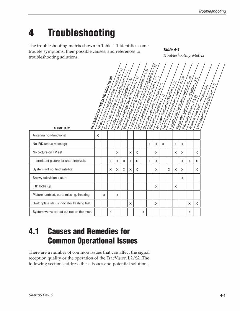
4 TroubleshootingThe troubleshooting matrix shown in Table 4-1 identifies sometrouble symptoms, their possible causes, and references totroubleshooting solutions.
4.1 Causes and Remedies forCommon Operational Issues
There are a number of common issues that can affect the signalreception quality or the operation of the TracVision L2/S2. Thefollowing sections address these issues and potential solutions.
4-1
Troubleshooting
54-0195 Rev. C
Table 4-1Troubleshooting Matrix
Antenna non-functional
No IRD status message
No picture on TV set
Intermittent picture for short intervals
System will not find satellite
Snowy television picture
IRD locks up
Picture jumbled, parts missing, freezing
Switchplate status indicator flashing fast
System works at rest but not on the move
Sat
ellit
e co
vera
ge is
sue
(Sec
tion
4.1.
4)
IRD
wiri
ng (S
ectio
n 4.
2.1)
LNB
ass
embl
y fa
ulty
(Sec
tion
4.3)
IRD
faul
ty (S
ectio
n 4.
2.6)
Sat
ellit
e si
gnal
blo
cked
(Sec
tion
4.1.
3)
Vehi
cle
turn
ing
durin
g st
artu
p (S
ectio
n 4.
1.5)
AC
pow
er fl
uctu
atin
g (S
ectio
n 4.
2.2)
PO
SS
IBLE
CA
US
E (A
ND
SO
LUTI
ON
)
SYMPTOM Ech
oSta
r IR
D a
ctiv
atio
n (S
ectio
n 4.
2.4)
Faile
d IR
D s
tatu
s ch
eck
(Sec
tion
4.2.
5)
Blo
wn
fuse
or i
mpr
oper
wiri
ng (S
ectio
n 4.
1.1)
Dew
or r
ain
pool
ing
on d
ome
(Sec
tion
4.1.
2)In
corr
ect o
r loo
se R
F co
nnec
tors
(Sec
tion
4.1.
6)
Type
of m
ultis
witc
h us
ed (S
ectio
n 4.
1.7)
Ant
enna
gyr
o fa
ulty
(Sec
tion
4.3)
No
IRD
dat
a co
nnec
tion
(Sec
tion
4.2.
3)
Sta
tiona
ry u
se o
nly
(Sec
tion
4.1.
8)
X
X X X X X
X X X X X X X
X X X X X X X X X X
X X X X X X X X X X
X
X X
X X
X X X X
X X X
4.1.1 Blown Fuse or Improper WiringIf the antenna unit is installed but entirely non-responsive, thereare two key factors to check as part of the troubleshootingprocess:
1. Blown Fuse – The antenna unit is equipped with afuse mounted on its CPU Board. If this fuse hasblown or been broken, the antenna unit will notoperate. Refer to Section 5.4.1, “PCB Removal andReplacement,” for details on the fuse location andhow to access the CPU Board.
2. Wiring – If the system has been improperly wired,the antenna unit will not operate correctly. Refer toSection 2.3, “Connecting System Components,” forcomplete system wiring information.
4.1.2 Dew or Rain Pooling on DomeDew or rain can occasionally pool on the top of the radome.While this moisture will usually be dispersed when the vehicle isin motion, it can disrupt the signal while the vehicle is at rest.This issue can be minimized with two approaches:
1. Using a hose, spray the dome with water toremove the dew from the dome surface.
2. Periodically apply liquid dish detergent to thedome surface. Wipe the full-strength detergent onthe dome and allow it to dry. This treatment willprovide a film that will help moisture bead up androll off the dome.
4.1.3 Satellite Signal BlockedSatellite signals can be blocked or degraded by trees andbranches, buildings, overpasses, mountains, or equipment on thevehicle itself. Refer to Section 2.1, “Choosing the Best Location,” tomake certain that the TracVision L2/S2 unit is in the optimallocation. Simply moving the vehicle to clear an externalobstruction will also restore signal quality.
4-2
A Guide to TracVision L2/S2

4.1.4 Satellite Coverage IssueTracVision L2/S2 will provide outstanding reception throughoutthe entire coverage area for your satellite television service ofchoice. However, signal quality can be degraded as you approachthe fringe coverage areas. Refer to your satellite television servicemanual to check the viable coverage area.
4.1.5 Vehicle Turning During Startup(TracVision L2 only)
If the vehicle turns during the 60-second startup andinitialization sequence that occurs immediately after turningon the power to the TracVision L2 unit, the antenna gyro willrecord that variable motion as “standing still.” This may causethe antenna to track improperly. To solve this problem, turn theTracVision L2 off for at least 10 seconds. Turn the system backon, making certain that the vehicle is either motionless ortraveling in a straight line for the 60 seconds immediatelyfollowing power-up.
4.1.6 Incorrect or Loose RF ConnectorsAs part of preventive maintenance (described in Section 5,“Maintenance”) KVH recommends checking the antenna unitcable connections. A loose RF connector can reduce the signalquality. Refer to Section 2.3.2, “Connecting the Antenna to the IRD,”for directions on proper antenna unit to RF cabling.
4.1.7 Type of Multiswitch UsedAn active (not passive) multiswitch must always be used toconnect the TracVision L2/S2 system to multiple IRDs. Refer toSection 2.3.2, “Connecting the Antenna to the IRD,” for directions onproper multiswitch/multiple IRD cabling.
4.1.8 Stationary Use Only (TracVision S2 only)The TracVision S2 antenna was designed for stationary use only.As such, the antenna will track the desired satellite while yourvehicle is parked, but not while the vehicle is in motion.
4-3
Troubleshooting
54-0195 Rev. C
Baseline RF levels are included aspart of the startup sequenceprovided in Appendix E.
For your convenience, KVHprovides links to several web sitesthat offer satellite coverageinformation. Simply go to our website at www.kvh.com/footprint.
KVH offers an upgrade kit (KVHPart #02-1026) that adds in-motiontracking capability to the TracVision S2, allowing you toreceive satellite signals while onthe move.

4.2 IRD TroubleshootingThe IRD that was provided with your satellite television servicemay also be the cause of less-than-ideal operation.
4.2.1 IRD WiringRefer to Section 2.3, “Connecting System Components,” and yourIRD user manual to confirm that the IRD is properly connected tothe antenna unit and the television.
4.2.2 AC Power FluctuatingIf the system periodically displays a picture for less than oneminute, then enters Search Mode 1, the IRD low-speed data portmay be locked up as the result of power fluctuations and willrequire a reset. This can be verified by hooking up a PC to themaintenance port and checking for error messages. Reset must bedone by:
1. Completely shutting down DC power to theantenna.
2. Remove the AC source, either at the breaker or byunplugging the IRD.
3. Wait at least 10 seconds before restoring power,first to the IRD and then to the antenna.
4.2.3 No IRD Data ConnectionTo view status messages, your TracVision antenna must beconnected to the IRD’s low-speed data port. Refer to Section 2.3.4, “Connecting the Switchplate to the IRD,” for details.
4.2.4 EchoStar IRD Activation CheckIf you have purchased a DISH Network system, there is a chancethat your EchoStar IRD will fail to acquire the satellite when youfirst activate it. This has been known to happen in IRDs that havenot been activated within several months of their manufacture.Appendix D provides the manual satellite acquisition andactivation procedure.
4-4
A Guide to TracVision L2/S2
The long-term fix, typically done atoriginal system installation, is toinstall an Uninterruptible PowerSupply (like those available for usewith computer systems) on the IRD.Be sure to specify a UPS withadequate available current for alldevices attached to it. (An IRDdraws approximately 200 watts.)

4.2.5 Failed IRD Status CheckAs detailed in Appendix E, TracVision L2/S2 completes a detailedstartup routine whenever it is turned on. One of the first checksis the IRD status test. As noted in the typical startup cycles, theexpectation is that the IRD and its communications link toTracVision L2/S2 will pass this test. There are, however, twoalternate results, each indicating a slightly different problem.
Test Result: NONE
If the system tests achieves a result of NONE, there is nocommunication at all between the antenna unit and the IRD.
Solution
Check to be certain the IRD and TracVision L2/S2 are connectedproperly at the low-speed data port and that both are poweredon. Refer to Section 2.3, “Connecting System Components,” forcorrect antenna unit to IRD wiring procedures and diagrams.After verifying the connection, cycle the power off and on andreview the startup test results.
Test Result: UNKNOWN
In the instance of a result of UNKNOWN, a communications linkexists, but the data received by the antenna unit is garbled andunrecognizable.
Solution
As with a result of NONE, first check to be certain the IRD andTracVision L2/S2 are connected properly at the low-speed dataport. Refer to Section 2.3, “Connecting System Components,” forcorrect antenna unit to IRD wiring procedures and diagrams.After verifying the connection, cycle the power off and on andreview the startup test results. If this does not initially succeed,refer to Section 4.2.2, “AC Power Fluctuating,” and follow the IRDreset procedure.
4.2.6 IRD FaultyIn the case of a faulty IRD, refer to your IRD user manual forservice, replacement, and warranty information.
4-5
Troubleshooting
54-0195 Rev. C

4.3 Antenna Gyro and LNB FaultsSection 5, “Maintenance,” provides detailed instructions forauthorized service personnel who may be required to replaceTracVision L2/S2 components. The TracVision S2 does not includean antenna gyro.
4.4 Computer DiagnosticsTracVision L2/S2 has been designed to provide diagnosticreadouts viewed on the TV screen (DIRECTV only) or on apersonal computer having an RS-232 serial communication port.If you are unable to isolate a system problem with the foregoingtroubleshooting tools, set up for computer diagnostics asdescribed below. System problems will most likely be foundsomewhere through the diagnostic readouts.
The diagnostics procedure requires terminal emulation softwaresuch as Windows Hyperterminal or PROCOMM. Use the settingsappropriate to your application.
1. Connect one end of a PC data cable to themaintenance port connector on the switchplate(see Figure 4-1). To access this connector, you mayneed to remove the switchplate from the mountingsurface.
2. Connect the other end of the PC data cable to theserial port on the PC (a 9-pin/25-pin connectoradapter may be needed for some PCs).
4-6
A Guide to TracVision L2/S2
Most terminal emulation programshave a parameter for localcharacter echo. Select thisparameter to see what is beingtyped without any system delay.
Figure 4-2PC Data Cable DB9 Connector
Maintenance Port(DB9 Connector)
Figure 4-1Switchplate Maintenance Port

3. Open the terminal emulation software andestablish the following settings:
• Bits per second: 9600
• Data bits: 8
• Parity: None
• Stop bits: 1
• Flow control: None
4. Apply power to the TracVision L2/S2 system andallow the system to complete full initialization.Data should be scrolling on the PC display toidentify any system problems detected. If no datais seen, recheck your connections and the terminalsoftware setup.
4.5 Maintenance Port ParserCommands
TracVision L2/S2 system parser commands are detailed in Appendix F.
4-7
Troubleshooting
54-0195 Rev. C

5-1
Maintenance
54-0195 Rev. C
5 MaintenanceThe following sections provide details on preventivemaintenance and field replaceable units and parts for theTracVision L2/S2 antenna unit.
5.1 Warranty/Service InformationFor information on KVH warranty, repair, and liability policies,please refer to the complete warranty statement provided at theconclusion of this manual. If you have any questions, please callyour local authorized dealer or installer, or contact KVH directly.
IMPORTANT! Before returning the product, be sure to obtainan RMA number from KVH’s Technical Support Departmentand write the number on the outside of the box. Shipmentsreceived without an RMA number will be returned to you atyour expense.
5.2 Preventive MaintenanceTracVision L2/S2 requires minimal preventive maintenance. Thefollowing tasks are sufficient to maintain peak performance.
Monthly• Wash the exterior of the radome and baseplate
assembly with fresh water; a mild detergent maybe added to remove grime. Do not spray theradome directly with high-pressure water.
• Do not apply abrasive cleaners or volatile solventssuch as acetone to the ABS radome.
Annually• Remove the radome. Visually inspect the elevation
drive shaft to be certain that it moves easily and isclear of grit and debris. Clean and lubricate withsilicone or white lithium grease as required.
Detailed information on KVH’sglobal support program and how tocontact KVH or a dealer near you isavailable at www.kvh.com/global_support.

5-2
A Guide to TracVision L2/S2
5.3 Replaceable PartsTracVision L2/S2 has been designed with durability and lowmaintenance in mind. If you experience an operating problem orotherwise require technical assistance, contact your localauthorized TracVision L2/S2 dealer/installer first. Have theantenna unit serial number ready with a list of the troublesymptoms. If an authorized dealer/installer is not located nearby,contact the factory directly at the telephone, facsimile, or e-maillistings inside the front cover.
Replacement part numbers for units that can be serviced in thefield are listed in Table 5-1. These parts may be obtained fromany KVH authorized dealer/installer.
Part Name Part Number
Radome Assembly (TracVision L2) 02-0953-09
Radome Assembly (TracVision S2) 02-0953-10
Baseplate Assembly (TracVision L2) 02-1244-01
Baseplate Assembly (TracVision S2) 02-1244-02
Data/Power Cable 32-0730-28
RF Cable 32-0417-28
CPU PCB 02-1144-01
Antenna Gyro (TracVision L2 only) 02-1035
Antenna Gyro Gasket (TracVision L2 only) 24-0139
System Fuse 16-0017-3150
LNB 19-0056
It is recommended that all other technical difficulties be resolvedby returning the TracVision L2/S2 unit to an authorized serviceprovider.
Table 5-1Field Replaceable Units
Should the fuse ever need to bereplaced, TracVision L2/S2 uses a 5x20mm, 3.15-amp, 250-volt fast-blow fuse.
The serial number of yourTracVision L2/S2 will be requiredduring any troubleshooting orservice calls. You will find the serial number on the inside frontcover of this manual.

5-3
Maintenance
54-0195 Rev. C
5.4 Field Replaceable UnitProcedures
The following subsections provide detailed procedures forrepairing or swapping out field replaceable units. The proceduresrefer to labeled items presented on the following diagrams.
PCB Cover
Pan Head Screws
PCB
Rotating Plate
3.15-amp Fuse
Always lift the antenna unit bythe gray baseplate, never by theradome or any portion of theantenna assembly!
Figure 5-1Antenna, PCB, and Rotating Plate
Antenna Gyro(TracVision L2 only)
E-ring
Elevation AxisMotor Shaft
Linear Actuator
Connecting Rod
Figure 5-2Close-up of Connecting Rod and E-ring
Before servicing the antenna unit,be sure to remove the appropriatevehicle fuse to disconnect power.Replace the fuse after completingthe service.

5-4
A Guide to TracVision L2/S2
Locking Nutsand Washers
Antenna Gyro
Antenna Gyro Cable
Reflector Bracket
Wing Screwand Washer
LNB Clamp
LNB
Antenna GyroGasket
TracVision L2 only
Figure 5-3Antenna Assembly
Azimuth Motor
PCB
Antenna Gyro Cable(TracVision L2 only)
Cable Clamp and Screw
Figure 5-4Rotating Plate
5-5
Maintenance
54-0195 Rev. C
5.4.1 PCB Removal and Replacement
Estimated Time to Repair: 1⁄2 hour
The microprocessor PCB assembly is protected by a coverfastened to the rotating plate – Fig. 5-1. The cover must beremoved to gain access to the main power fuse and the PCBassembly.
1. Using needle-nose pliers, remove the E-ring fromone end of the connecting rod – Fig. 5-2.
2. Remove the connecting rod by sliding it off thebracket.
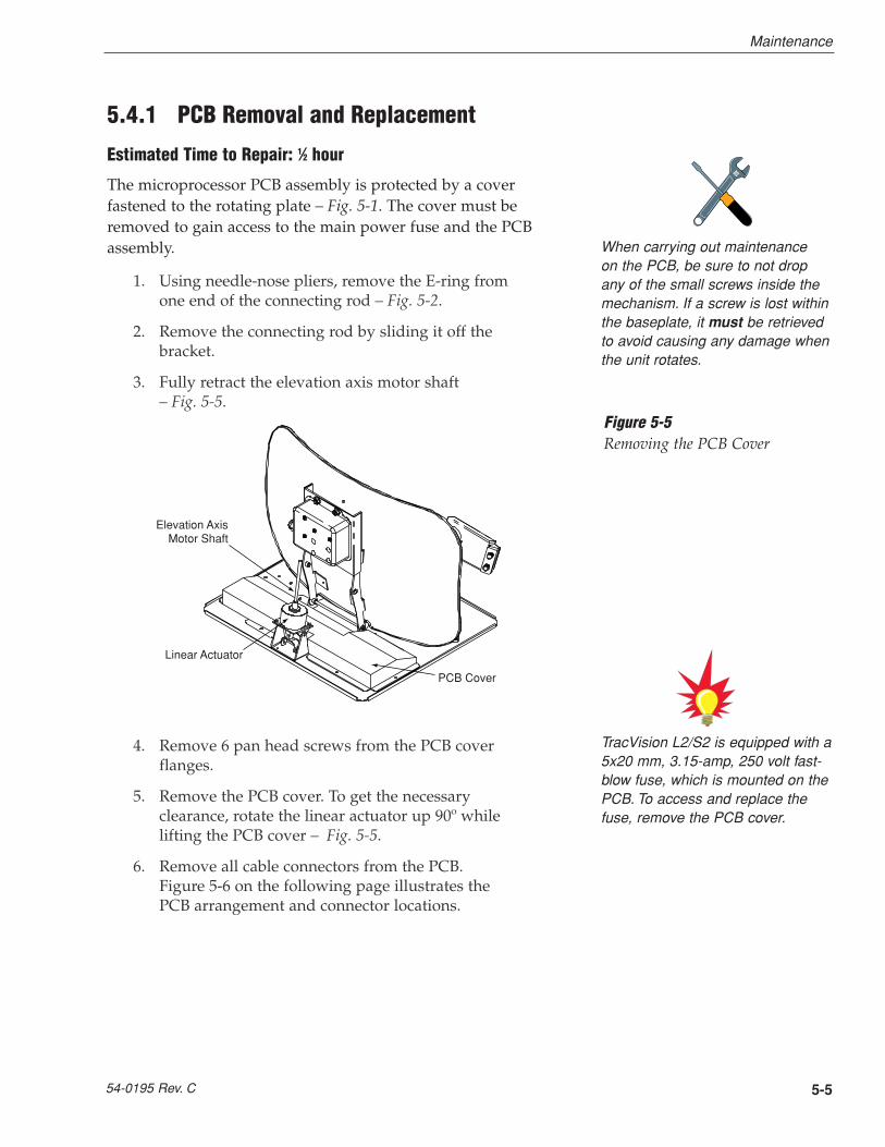
3. Fully retract the elevation axis motor shaft – Fig. 5-5.
4. Remove 6 pan head screws from the PCB coverflanges.
5. Remove the PCB cover. To get the necessaryclearance, rotate the linear actuator up 90º whilelifting the PCB cover – Fig. 5-5.
6. Remove all cable connectors from the PCB. Figure 5-6 on the following page illustrates thePCB arrangement and connector locations.
TracVision L2/S2 is equipped with a5x20 mm, 3.15-amp, 250 volt fast-blow fuse, which is mounted on thePCB. To access and replace thefuse, remove the PCB cover.
When carrying out maintenance on the PCB, be sure to not dropany of the small screws inside themechanism. If a screw is lost withinthe baseplate, it must be retrievedto avoid causing any damage whenthe unit rotates.
PCB Cover
Linear Actuator
Elevation AxisMotor Shaft
Figure 5-5Removing the PCB Cover

5-6
A Guide to TracVision L2/S2
7. Remove the 9 pan head screws securing the PCBto the rotating plate.
8. Reverse this process to install the replacementPCB. Reinstall all cable connectors removed inStep 6.
9. Carry out the LNB calibration procedure (Section 5.4.3).
5.4.2 Antenna Gyro Assembly (TracVision L2 only)
Estimated Time to Repair: 1 hour
The antenna gyro assembly is mounted on the rear of the antennareflector bracket with four locking nuts and washers – Fig. 5-3.Following the removal and replacement of the antenna gyroassembly, it will be necessary to calibrate the gyro and restart thesystem. Directions for removal, replacement, and calibrationfollow:
1. Using needle-nose pliers, remove the E-ring fromone end of the connecting rod – Fig. 5-2.
2. Remove the connecting rod by sliding it off thebracket.
3. Fully retract the elevation axis motor shaft – Fig. 5-5.
PCB
Limit Switches
Gyro(TracVision L2 only)
RF Connectorto IRD
RF Connectorto LNB
Elevation Motor Azimuth Motor
Cable Wrap
Fuse
J11
J2 J1
J4
Figure 5-6PCB Connector Locations –
Rear View
When replacing the PCB cover, becareful not to pinch any cables.

5-7
Maintenance
54-0195 Rev. C
4. Remove 6 pan head screws from the PCB coverflanges.
5. Remove the PCB cover. To get the necessaryclearance, rotate the linear actuator up 90º whilelifting the PCB cover – Fig. 5-5.
6. Remove the screw and clamp holding the cable tothe rotating plate; save the cable clamp for reuse –Fig. 5-4.
7. Remove the Molex connector from J11 on the CPUboard – Fig. 5-6.
8. Remove the 4 locking nuts and flat washers andtake the antenna gyro off the bracket.
9. Remove the antenna gyro gasket.
10. Replacement is the reverse of this procedure.
Antenna Gyro Calibration1. Connect a PC to the communications port as
described in Section 4.4, “Computer Diagnostics.”
2. Type HALT<cr> (<cr> indicates a carriage return/ENTER key) while the system is performing thelimit switch initialization routine. The system willcomplete the initialization function by finding theazimuth and elevation switch limits and then go tothe home position.
3. Type DEBUGON<cr> to enter Debug Mode.
4. Type EL,300<cr>.
5. Type =CALAZ<cr>. Verify that the Antenna GyroAzimuth scale factor is between -0.00090 and -0.00110.
6. Type =CALEL<cr>. Verify that the Antenna GyroElevation scale factor is between 0.00090 and0.00110.
7. Type ZAP to restart/reinitialize the system.

5-8
A Guide to TracVision L2/S2
5.4.3 Antenna LNB Replacement
Estimated Time to Repair: 1⁄2 hour
The LNB receives preamplifier operating power from the IRD viathe PCB – Fig. 5-3 and 5-4. Be certain that the IRD is disconnectedfrom its power source before removing or reconnecting the LNB.
1. Disconnect both RF coaxial connectors at the LNB.
2. Remove the wing screw and washer from the LNBclamp – Fig. 5-3.
3. Remove the top of the LNB clamp – Fig. 5-3.
4. Remove the LNB.
5. Replacement is the reverse of this procedure.Check the rotation to ensure that the LNB is notstriking any wires or the baseplate.
Antenna LNB Normalization and Stability Test1. Connect a PC to the maintenance port as described
in Section 4.4, “Computer Diagnostics.”
2. Ensure that the antenna is tracking the satellite.
3. Type HALT<cr> (<cr> indicates a carriage return/ENTER key) to put the system into Idle Mode.
4. Type DEBUGON<cr> to put the system intoDebug Mode.
5. Type FINDSAT<cr> to begin the automatic signalpeaking process. Wait until the antenna peaks thesatellite signal and is motionless. The screen willdisplay FINDSAT: PASS.
6. Type =CALLNB<cr> to start the LNBNormalization Function.
Note: The CALLNB Function requires the antennato be pointed directly at the satellite peak beforeperforming this routine.
7. The system must respond with the followingmessage: CALLNB: PASS. If the system displaysCALLNB: FAIL, return to Step 3 and retry theprocedure, making sure to achieve the highestpossible RF signal peak.
8. Record the Cold Sky Average and the RFGAINvalue reported in Step 7.
The CALLNB Function requires theantenna to be pointed directly atthe satellite peak before performingthis routine. Using the FINDSATcommand will ensure that theantenna is receiving the strongestpossible signal.
When replacing the LNB, makecertain to restore it to its originalorientation, as shown in Figure 5-3.

9. Type ZAP<cr>. The system will re-initialize usingthe new RFGAIN and RFOFFSET scale factorsdisplayed following Step 7.
10. Wait for the system to perform the backgroundnoise calculation. Read the Average Noise Levelvalue from the messages transmitted out themaintenance port. This value must be greater than300 and less than 1300. An example of the messagesequence and format is as follows:
*** Averaging Background Noise ***
Average Noise Level = 750
Noise Threshold = 1450
11. Wait for the system to search for, find the satellite,enter Tracking Mode and track the satellite for aminimum of 30 seconds. Record the average RFsignal value reported from the +POS: AZ, EL, RFmessages. An example of the message sequenceand format is as follows:
+POS: 154.5 33.2 2521
12. The RF signal values while tracking shall begreater than 2000 and less than 3000.
5-9
Maintenance
54-0195 Rev. C

5.5 Preparation for ShipmentIf you need to repack the antenna unit for shipment, theshipping restraints removed or stowed during installationmust be replaced. Follow these steps to reinstall the restraints.
1. Remove the radome.
2. Rotate the antenna unit so that the LNB is facingaway from the baseplate connectors.
3. Attach the three restraints to the baseplate usingthe 1⁄4"-20 x 5⁄8" hex screws and washers provided inthe kitpack and the nuts and washers removedfrom the baseplate, as pictured in Figure 5-7.
4. Place the antenna bracket on the forward shippingrestraint.
5. Secure the forward restraint and bracket bywrapping two tie-wraps around the bend in theforward restraint and the antenna bracket (at theend of the LNB bracket).
6. Replace the radome.
7. Place the entire antenna unit into its shipping boxusing the original packaging material. Secure thebox to a pallet to ensure upright transport to KVH.
5-10
A Guide to TracVision L2/S2
When rotating the azimuthmechanism by hand, go slowly!Hitting the mechanical stops withexcessive force will damage theazimuth limit switch.
KVH is not liable for damagecaused by improper shipping.
� ������� ���
� ����� ��� ���
� ����� ������ ��������
� ����� ������ ��������
��� ��� �����
��� ����� ��� �����
Figure 5-8Securing the Forward
Shipping Restraint
Figure 5-7Attaching the Shipping Restraints
to the Antenna Baseplate
Before returning the product, besure to obtain an RMA numberfrom KVH’s Technical SupportDepartment and write thenumber on the outside of thebox. Shipments received withoutan RMA number will be returnedto you at your expense.

Appendix ASystem SpecificationsPhysical Characteristics
Power 11-16 volts DC @ 2.5 ampsnominal, 3.5 amps peak
Dimensions/Weight 32" wide x 14.8" high, 33 lbs
LNB Dual Output
Tracking (TracVision L2 only) Better than 30º/sec
Maintenance Port 9600 bps, 8,N,1,EIA, RS232
Pointing System
Elevation Range 15º to 75º
Azimuth Range 720º
Position Repeatability 0.1º
Environmental
Operating Temperature -13ºF to +131ºF
Storage Temperature -40ºF to +185ºF
Humidity to 100 percent
Table A-1TracVision L2/S2 SystemSpecifications
A-1
System Specifications
54-0195 Rev. C

Appendix BComprehensive SystemWiring DiagramThe wiring diagram is presented on the following page.
B-1
Comprehensive System Wiring Diagram
54-0195 Rev. C

VE
HIC
LE

Appendix CSwitchplate Template
C-1
Switchplate Template
54-0195 Rev. C
2.5"
2"

Appendix DEchoStar IRD ActivationProcedureIf you have purchased a DISH Network system, there is a chancethat your EchoStar IRD will fail to acquire the satellite when youfirst activate it. This has been known to happen in IRDs that havenot been activated within several months of their manufacture.The following process is a manual method of acquiring thesatellite for the first time so that the IRD can download the mostup-to-date satellite and programming data, allowing it toautomatically acquire the satellite from then on.
Please refer to your EchoStar IRD user manual for completeinstructions on the IRD, the remote control, and the commandscreens.
Manual Satellite Acquisition and IRD Activation1. Turn on the TV and EchoStar IRD.
2. Using the EchoStar remote, press MENU.
- The Main Menu will come up on the screen.
3. Select #6, System Setup.
4. Select #1, Installation.
5. Select #1, Point Dish/Signal.
- The Signal Strength Screen will appear.
6. Using the remote, select the zip code box on thescreen, and input the local zip code.
- The screen will show you the Azimuth andElevation to the satellite. Write this down.
7. Connect a PC to the antenna switchplate’smaintenance port.
8. Turn on the TracVision L2/S2.
9. Type HALT<cr> (<cr> indicates a carriage return/ENTER key) after receiving the message *** Entering Search Mode 1 ***.
D-1
EchoStar IRD Activation Procedure
54-0195 Rev. C
It will be necessary to have a PCavailable to complete the manualacquisition and activationprocedure.

10. Type in the elevation that you obtained in Step 6.
- Type EL,xxx<cr>(e.g., Elevation of 30.2° = EL,302<cr>)
11. Using a compass, take a bearing on an object thatis approximately on the azimuth obtained in Step 6.
12. Type in an azimuth that points the antenna in thedirection of the object selected in Step 11.
- Type AZ,xxxx<cr>(e.g., azimuth of 233° = AZ,2330<cr>)
- Valid azimuth range is 0-360° (0000-3600)
13. Check to see if there is signal strength on theSignal Meter Screen.
14. Move antenna counter-clockwise in 5° incrementsuntil signal strength is acquired. If you do not findthe satellite, point the antenna at the objectselected in Step 11 and move the antennaclockwise in 5° increments until signal strength isacquired.
15. Once the satellite is found, fine tune azimuth in 1°increments for maximum signal strength.
16. Fine tune elevation in 1° increments for maximumsignal strength.
17. Once the satellite is found, turn the EchoStar IRDoff, using the power button on the infrared remote.Do not turn off the IRD using the front panel. LeaveIRD in standby mode for approximately 5 minutes.The IRD will now download new software fromthe satellite.
- To verify that the IRD has been updated, put theIRD into the Signal Strength Screen mode, andthree satellite options will appear on the left sideof the screen: 61.5° West, 119° West, 148° West.Your EchoStar IRD is now updated.
D-2
A Guide to TracVision L2/S2
The Signal Strength Meter islocated on the bottom of the “PointDish and Signal Strength” Screen.This Signal Strength Meter is Redin color, and turns Green when theproper satellite is located.
Turning the IRD off with the remoteputs the IRD in standby mode.Turning the IRD off from the frontpanel shuts the IRD off.

Appendix EStartup Data SequencesThe data on the following pages presents the startup datasequences registered by the TracVision L2/S2. The first part of each section shows the sequences registered by a system that is connected to an IRD low-speed data port. The second part of eachsection shows the sequences registered by a system that is NOTconnected to an IRD low-speed data port. Both parts show two routines. One is the standard, full initialization routine; the secondis that registered by TracVision L2/S2 if it is turned on and acquires the satellite via the “Instant On” operation (described in Section 3, “Using Your TracVision L2/S2”). These sequences can berecorded using the data port and a PC.
E.1 TracVision L2 SequencesE.1.1 System Connected to IRD Data
Standard Startup Sequence
?PGM
KVH TracVision L2 Rev X - Version X.XX - Serial number XXXXXXXX
Limit Switch Test
Limit Switch Status:PASS------------------Pass is expected
*** Initializing IRD ***
IRD STATUS: PASS DSS -------------------PASS is expected with successful IRD identification
Saved Sat Pos: EL = 36.5
*** Initializing Rate Bias ***
+POS: 45.0 45.9 548
VEL_INDEX: Az = 1996, El = 2182 ----------Expected range is 1700-2300
RATE BIAS: PASS---------------------------Az & El values above are within valid ranges
*** Averaging Background Noise ***
+POS: 45.0 22.5 356
+POS: 135.0 20.0 362
+POS: 311.8 20.0 355
Average Noise Level = 381
Noise Threshold = 859
Saved Sat Pos: EL = 36.5
*** Entering Search Mode 1 ***
+POS: 27.0 20.1 354
+POS: 79.9 36.4 341
E-1
Startup Data Sequences
54-0195 Rev. C

E-2
A Guide to TracVision L2/S2
Satellite Found: AZ = 62.26, EL = 36.50, RF = 1300
+POS: 53.6 36.5 449
*** Entering Tracking ***
+POS: 61.8 36.5 1260
+POS: 62.2 36.3 1346
+POS: 64.0 36.5 1716
*** Entering Satellite Check *** --------Confirming proper satellite lock
+POS: 64.3 36.1 1747
Satellite Located
IRD Signal Quality = 54
+POS: 66.1 35.6 1522
+POS: 64.6 35.5 1749
IRD Signal Quality = 58
+POS: 66.2 36.1 1467
“Instant On” Startup Sequence
?PGM
KVH TracVision L2 Rev X - Version X.XX - Serial Number XXXXXXXX
Instant On--------------------------------System skips limit switch test
Limit Switch Status: PASS-----------------PASS is expected
*** Initializing IRD ***
...
IRD STATUS: PASS DSS --------------------PASS is expected with successful IRD
identification
Saved Sat Pos: EL = 33.3
*** Initializing Rate Bias ***
+POS: 360.0 33.9 2625
VEL_INDEX: Az = 1996, El = 2182 ---------Expected range is 1700-2300
RATE BIAS: PASS --------------------------Az & El values above are within valid ranges
*** Initializing Finetune ***-------------Peaking the satellite signal
+POS: 360.0 33.9 2622
Signal Peaked: AZ = 0.00, EL = 33.30, RF = 2674
+POS: 0.0 33.3 2646
+POS: 0.0 33.3 2638
IRD Signal Quality = 79
+POS: 0.0 33.3 2640
+POS: 0.0 33.3 2614
IRD Signal Quality = 77
CH = 200 XP = 7 HI = 0 LO = 10
+POS: 0.0 33.3 2652
Saved Sat Pos: AZ = 0.00, EL = 33.30
+POS: 0.0 33.3 2617
+POS: 0.0 33.3 2616
IRD Signal Quality = 78

E.1.2 System Not Connected to IRD Data
Standard Startup Sequence
?PGM
KVH TracVision L2 Rev X - Version X.XX - Serial Number XXXXXXXX
Limit Switch Test
Limit Switch Status: PASS-----------------PASS is expected
*** Initializing IRD ***
Send APG OSD On
Try MPG IRD Type
Send MPG OSD On
Switch Back to Echostar IRD Type
Send APG OSD On
Try MPG IRD Type
Send MPG OSD On
Switch Back to Echostar IRD Type
IRD STATUS: FAIL None -------------------FAIL is expected with no IRD data connection
Saved Sat Pos: EL = 33.5
*** Initializing Rate Bias ***
+POS: 360.0 33.9 2625
VEL_INDEX: Az = 1996, El = 2182 ---------Expected range is 1700-2300
RATE BIAS: PASS --------------------------Az & El values above are within valid ranges
*** Averaging Background Noise ***
+POS: 45.0 26.3 762
+POS: 62.1 20.0 1111
+POS: 223.5 20.0 1082
Average Noise Level = 985
Nor = 1826
Saved Sat Pos: EL = 33.5
*** Entering Search Mode 1 ***
+POS: 193.4 30.1 1098
+POS: 205.8 33.5 878
Satellite Found: AZ = 330.0, EL = 33.5, RF = 2150
+POS: 0.9 33.5 586
+POS: 331.2 33.5 2173
*** Initializing Finetune ***-------------Peaking the satellite signal
+POS: 331.2 33.5 2197
+POS: 331.8 34.1 2177
Signal Peaked: AZ = 331.79, EL = 33.50, RF = 2226
*** Tracking Satellite ***
+POS: 331.7 33.4 2154
+POS: 331.7 33.4 2167
Saved Sat Pos: AZ = 331.75, EL = 33.43
+POS: 331.7 33.4 2155
+POS: 331.7 33.4 2132
E-3
Startup Data Sequences
54-0195 Rev. C

+POS: 331.7 33.4 2153
Switch held: wrong satellite--------------SAT SELECT switch pressed
Exclude: No longer search AZ = 331.7, EL = 33.4
*** Entering Search Mode 1 *** -----------Searching for a different satellite
Search1 decided to go to: AZ = 335.9, EL = 33.5
+POS: 23.5 33.5 518
+POS: 162.5 33.5 1105
*** Entering Search Mode 2 ***
+POS: 150.5 33.4 1108
+POS: 80.1 33.4 889
+POS: 180.0 34.0 1092
*** Entering Search Mode 3 ***
+POS: 180.0 34.3 873
+POS: 66.6 22.0 885
Satellite Found: AZ = 348.8, EL = 22.0, RF = 2149
+POS: 327.4 22.0 567
*** Initializing Finetune ***
+POS: 348.8 22.0 1987
+POS: 348.8 23.8 1965
Signal Peaked: AZ = 348.77, EL = 23.23, RF = 2004
*** Tracking Satellite ***
+POS: 348.8 23.3 2100
+POS: 348.8 23.3 1840
Saved Sat Pos: AZ = 348.76, EL = 23.29
+POS: 348.8 23.3 2190
+POS: 348.8 23.3 2010
“Instant On” Startup Sequence
?PGM
KVH TracVision L2 Rev X - Version X.XX - Serial Number XXXXXXXX
Instant On--------------------------------System skips limit switch test
Limit Switch Status: PASS-----------------PASS is expected
*** Initializing IRD ***
Send APG OSD On
Try MPG IRD Type
Send MPG OSD On
Switch Back to Echostar IRD Type
Send APG OSD On
Try MPG IRD Type
Send MPG OSD On
Switch Back to Echostar IRD Type
IRD STATUS: FAIL None ------------------FAIL is expected with no IRD data connection
Saved Sat Pos: EL = 22.5
*** Initializing Rate Bias ***
+POS: 360.0 33.9 2625
E-4
A Guide to TracVision L2/S2

VEL_INDEX: Az = 1996, El = 2182 ----------Expected range is 1700-2300
RATE BIAS: PASS --------------------------Az & El values above are within valid ranges
*** Initializing Finetune ***
+POS: 360.0 23.1 1575
Signal Peaked: AZ = 0.00, EL = 22.50, RF = 1919
*** Tracking Satellite ***
+POS: 360.0 22.5 1917
+POS: 360.0 22.5 1976
Switch held: wrong satellite--------------SAT SELECT switch pressed
Exclude: No longer search AZ = 0.0, EL = 22.5
KVH TracVision L2 Rev X - Version X.XX - Serial Number XXXXXXXX
Limit Switch Test
Limit Switch Status: PASS
*** Initializing IRD ***
Send APG OSD On
Try MPG IRD Type
Send MPG OSD On
Switch Back to Echostar IRD Type
Send APG OSD On
Try MPG IRD Type
Send MPG OSD On
Switch Back to Echostar IRD Type
IRD STATUS: FAIL None
Saved Sat Pos: EL = 22.5
*** Initializing Rate Bias ***
+POS: 360.0 33.9 2625
VEL_INDEX: Az = 1996, El = 2182 ---------Expected range is 1700-2300
RATE BIAS: PASS --------------------------Az & El values above are within valid ranges
*** Averaging Background Noise ***
+POS: 45.0 26.3 956
+POS: 62.1 20.0 1094
+POS: 223.5 20.0 850
Average Noise Level = 965
Noise Threshold = 1794
Saved Sat Pos: EL = 22.5
*** Entering Search Mode 1 *** -----------Searching for a different satellite
+POS: 193.4 22.5 869
+POS: 205.8 22.5 1083
Satellite Found: AZ = 350.6, EL = 22.5, RF = 2015
+POS: 15.0 22.5 471
+POS: 354.0 22.5 620
*** Initializing Finetune ***
+POS: 350.0 22.5 1773
+POS: 350.5 21.9 1959
Signal Peaked: AZ = 350.55, EL = 22.50, RF = 1978
*** Tracking Satellite ***
+POS: 350.5 22.4 1674
E-5
Startup Data Sequences
54-0195 Rev. C

E.2 TracVision S2 SequencesE.2.1 System Connected to IRD Data
Standard Startup Sequence
?PGM
KVH TracVision S2 Rev X - Version X.XX - Serial Number XXXXXXXX
Limit Switch Test
Limit Switch Status: PASS-----------------PASS is expected
*** Initializing IRD ***
..
IRD STATUS: PASS DSS --------------------PASS is expected with success2ul IRD
identification
Saved Sat Pos: EL = 33.4
*** Averaging Background Noise ***
+POS: 45.0 26.6 735
+POS: 57.9 20.0 1004
+POS: 232.0 20.0 812
+POS: 25.6 20.0 898
Average Noise Level = 957
Noise Threshold = 1781
Saved Sat Pos: EL = 33.4
*** Entering Search Mode 1 ***
+POS: 80.9 32.1 1217
+POS: 44.6 33.4 853
Satellite Found: AZ = 327.7, EL = 33.4, RF = 2476
+POS: 306.4 33.4 1020
*** Initializing Finetune ***-------------Peaking the satellite signal
+POS: 327.7 33.4 2827
+POS: 327.7 33.9 2717
Signal Peaked: AZ = 327.69, EL = 33.40, RF = 2822
+POS: 327.7 33.3 2751
+POS: 327.7 33.3 2741
*** Entering Satellite Check ***
+POS: 327.7 33.3 2756
Signal Detected = 82
+POS: 327.7 33.3 2727
Signal Detected = 81
+POS: 327.7 33.3 2731
+POS: 327.7 33.3 2713
Tracking DSS satellite at 101.5W
+POS: 327.7 33.3 2665
IRD Signal Quality = 79
+POS: 327.7 33.3 2708
Saved Sat Pos: AZ = 327.70, EL = 33.34
E-6
A Guide to TracVision L2/S2

“Instant On” Startup Sequence
?PGM
KVH TracVision S2 Rev X - Version X.XX - Serial Number XXXXXXXX
Instant On--------------------------------System skips limit switch test
Limit Switch Status: PASS-----------------PASS is expected
*** Initializing IRD ***
...
IRD STATUS: PASS DSS --------------------PASS is expected with success2ul IRD identification
Saved Sat Pos: EL = 33.3
*** Initializing Finetune ***-------------Peaking the satellite signal
+POS: 360.0 33.9 2622
Signal Peaked: AZ = 0.00, EL = 33.30, RF = 2674
+POS: 0.0 33.3 2646
+POS: 0.0 33.3 2638
IRD Signal Quality = 79
+POS: 0.0 33.3 2640
+POS: 0.0 33.3 2614
IRD Signal Quality = 77
CH = 200 XP = 7 HI = 0 LO = 10
+POS: 0.0 33.3 2652
Saved Sat Pos: AZ = 0.00, EL = 33.30
+POS: 0.0 33.3 2617
+POS: 0.0 33.3 2616
IRD Signal Quality = 78
+POS: 0.0 33.3 2610
E.2.2 System Not Connected to IRD Data
Standard Startup Sequence
?PGM
KVH TracVision S2 Rev X - Version X.XX - Serial Number XXXXXXXX
Limit Switch Test
Limit Switch Status: PASS-----------------PASS is expected
*** Initializing IRD ***
Send APG OSD On
Try MPG IRD Type
Send MPG OSD On
Switch Back to Echostar IRD Type
Send APG OSD On
Try MPG IRD Type
Send MPG OSD On
E-7
Startup Data Sequences
54-0195 Rev. C

Switch Back to Echostar IRD Type
IRD STATUS: FAIL None -------------------FAIL is expected with no IRD data connection
Saved Sat Pos: EL = 33.5
*** Averaging Background Noise ***
+POS: 45.0 26.3 762
+POS: 62.1 20.0 1111
+POS: 223.5 20.0 1082
Average Noise Level = 985
Nor = 1826
Saved Sat Pos: EL = 33.5
*** Entering Search Mode 1 ***
+POS: 193.4 30.1 1098
+POS: 205.8 33.5 878
Satellite Found: AZ = 330.0, EL = 33.5, RF = 2150
+POS: 0.9 33.5 586
+POS: 331.2 33.5 2173
*** Initializing Finetune ***-------------Peaking the satellite signal
+POS: 331.2 33.5 2197
+POS: 331.8 34.1 2177
Signal Peaked: AZ = 331.79, EL = 33.50, RF = 2226
*** Tracking Satellite ***
+POS: 331.7 33.4 2154
+POS: 331.7 33.4 2148
+POS: 331.7 33.4 2167
Saved Sat Pos: AZ = 331.75, EL = 33.43
+POS: 331.7 33.4 2155
+POS: 331.7 33.4 2132
+POS: 331.7 33.4 2153
Switch held: wrong satellite--------------SAT SELECT switch pressed
Exclude: No longer search AZ = 331.7, EL = 33.4
*** Entering Search Mode 1 *** -----------Searching for a different satellite
Search1 decided to go to: AZ = 335.9, EL = 33.5
+POS: 23.5 33.5 518
+POS: 135.5 33.5 890
+POS: 162.5 33.5 1105
*** Entering Search Mode 2 ***
+POS: 150.5 33.4 1108
+POS: 80.1 33.4 889
+POS: 180.0 34.0 1092
*** Entering Search Mode 3 ***
+POS: 180.0 34.3 873
+POS: 66.6 22.0 885
Satellite Found: AZ = 348.8, EL = 22.0, RF = 2149
+POS: 327.4 22.0 567
*** Initializing Finetune ***
+POS: 348.8 22.0 1987
+POS: 348.7 22.6 2020
+POS: 348.8 23.8 1965
Signal Peaked: AZ = 348.77, EL = 23.23, RF = 2004
E-8
A Guide to TracVision L2/S2

*** Tracking Satellite ***
+POS: 348.8 23.3 2100
+POS: 348.8 23.3 1840
Saved Sat Pos: AZ = 348.76, EL = 23.29
+POS: 348.8 23.3 2190
+POS: 348.8 23.3 2010
“Instant On” Startup Sequence
?PGM
KVH TracVision S2 Rev X - Version X.XX - Serial Number XXXXXXXX
Instant On--------------------------------System skips limit switch test
Limit Switch Status: PASS-----------------PASS is expected
*** Initializing IRD ***
Send APG OSD On
Try MPG IRD Type
Send MPG OSD On
Switch Back to Echostar IRD Type
Send APG OSD On
Try MPG IRD Type
Send MPG OSD On
Switch Back to Echostar IRD Type
IRD STATUS: FAIL None ------------------FAIL is expected with no IRD data connection
Saved Sat Pos: EL = 22.5
*** Initializing Finetune ***
+POS: 360.0 23.1 1575
Signal Peaked: AZ = 0.00, EL = 22.50, RF = 1919
*** Tracking Satellite ***
+POS: 360.0 22.5 1917
+POS: 360.0 22.5 1635
+POS: 360.0 22.5 1976
Switch held: wrong satellite--------------SAT SELECT switch pressed
Exclude: No longer search AZ = 0.0, EL = 22.5
KVH TracVision S2 Rev X - Version X.XX - Serial Number XXXXXXXX
Limit Switch Test
Limit Switch Status: PASS
*** Initializing IRD ***
Send APG OSD On
Try MPG IRD Type
Send MPG OSD On
Switch Back to Echostar IRD Type
Send APG OSD On
Try MPG IRD Type
Send MPG OSD On
E-9
Startup Data Sequences
54-0195 Rev. C

Switch Back to Echostar IRD Type
IRD STATUS: FAIL None
Saved Sat Pos: EL = 22.5
*** Averaging Background Noise ***
+POS: 45.0 26.3 956
+POS: 62.1 20.0 1094
+POS: 223.5 20.0 850
Average Noise Level = 965
Noise Threshold = 1794
Saved Sat Pos: EL = 22.5
*** Entering Search Mode 1 *** -----------Searching for a different satellite
+POS: 193.4 22.5 869
+POS: 205.8 22.5 1083
Satellite Found: AZ = 350.6, EL = 22.5, RF = 2015
+POS: 15.0 22.5 471
+POS: 354.0 22.5 620
*** Initializing Finetune ***
+POS: 350.0 22.5 1773
+POS: 350.5 21.9 1959
Signal Peaked: AZ = 350.55, EL = 22.50, RF = 1978
*** Tracking Satellite ***
+POS: 350.5 22.4 1674
E-10
A Guide to TracVision L2/S2

Appendix FMaintenance Port ParserCommandsTracVision L2/S2 system parser commands are parsed when thesystem receives an ASCII carriage return (Hex 0D). An ASCII linefeed (Hex 0A) is permitted but is ignored in any transmittedcommand. All system responses are terminated with an ASCIIcarriage return followed by a line feed and ending with either anacknowledge character (ASCII > (Hex 3E)) or a not-acknowledgecharacter (ASCII ? (Hex 3F)). The parser commands are shownbelow in boldface capital letters but they are not case-sensitive. Inmost cases the command is responded to with an echo; that is, ifyou type ZAP, for example, and press “ENTER,” the response willbe the command you have entered (i.e., ZAP). For other commandsthe response is specific for each command, such as VERSION,STATUS, or HELP.
F.1 System CommandsSoftware Version
Function reports software version
Command VERSION
Argument none
Response KVH TVL2/S2 Version XX.XX
System Status Report
Function: reports general system status
Command: STATUS
Argument: none
Response: system status string, (TBD)
Initialize the System
Function: initializes the system (perform a soft reset)
Command: ZAP
Argument: none
Response: echoes the command, then reinitializes the system
F-1
Maintenance Port Parser Commands
54-0195 Rev. C
Table F-1System Commands

F.2 Manual Positioning CommandsTo execute the following commands, first put the antenna unit inidle mode by typing HALT and pressing “ENTER.” Positioningcommands may be entered after the antenna comes to rest.
Help on Parser Commands
Function: lists parser commands
Command: HELP
Argument: none
Response: print a list of all parser commands
Azimuth Angle
Function: commands a manual azimuth angle that themechanism moves to
Command: AZ,xxxx (range is 0000-3599)
Argument: desired azimuth angle of the mechanism relative to vehicle reference, or baseplate fwd, 000º-359.9º (vehicle-referenced)
Response: echoes the command; mechanism moves at a fixedvelocity
Elevation Angle
Function: commands a manual elevation angle that themechanism moves to
Command: EL,xxx (range is 100-700)
Argument: desired elevation angle of the mechanism relative toup, or external sensor attitude reference, 10.0º-70.0º
Response: echoes the command; mechanism moves at a fixedvelocity
Azimuth CW Step
Function: commands a 0.1 deg CW manual step in azimuthangle
Command: 6
Argument: none
Response: echoes the command
F-2
A Guide to TracVision L2/S2
Table F-2Manual Positioning Commands

Azimuth CCW Step
Function: commands a 0.1 deg CCW manual step in azimuthangle
Command: 4
Argument: none
Response: echoes the command
Elevation UP Step
Function: commands a 0.1 deg UP manual step in elevation angle
Command: 8
Argument: none
Response: echoes the command
Elevation DOWN Step
Function: commands a 0.1 deg DOWN manual step in elevation angle
Command: 2
Argument: none
Response: echoes the command
F.3 Operational CommandsIdle Mode
Function: halts active tracking and conical scan, then enters idle mode
Command: HALT
Argument: none
Response: echoes the command
Current Cable Wrap Angle
Function: sets or reports current cable wrap angle, defined as 0º (CCW limit) to 700º (CW limit); the value isexpressed as 0000-7000 with an implied decimal
Command: WRAPANGLE,xxxx
Argument: the desired cable wrap angle setting
Response: Wrap Angle = xxxf
F-3
Maintenance Port Parser Commands
54-0195 Rev. C
Table F-3Operational Commands

F.4 Target and Signal CommandsReport Target Location
Function: reports the target (satellite) location in the baseplateframe and uses the saved satellite position
Command: TGTLOCATION
Argument: none
Response: Target Location = E XXX, A XXXX
Report RF Signal Strength
Function: reports the modified signal strength from the RF powerdetector circuit, and applies the RF gain and offsetcomputed during LNB calibration
Command: SIGLEVEL
Argument: none
Response: Signal Strength = XXXX
Report IRD Signal Quality
Function: reports the signal strength from the IRD; it uses the lastreceived signal quality and initiates a new signal qualityrequest command from the IRD
Command: SIGQUALITY
Argument: none
Response: Stale Signal Quality = XX
Report IRD Type
Function: reports the IRD connection type as DSS (DIRECTV),EchoStar, untested, or none
Command: IRDTYPE
Argument: none
Responses: IRD type has not been tested yet.IRD type is Echostar.IRD type is DSS.IRD type cannot be determined.
F-4
A Guide to TracVision L2/S2
Table F-4Target and Signal Commands

KVH Industries Limited Warranty TracVision L2/S2
Limited Warranty on HardwareKVH Industries, Inc. warrants the KVH product purchased against defects in materials for a period of TWO (2) yearsand against factory labor costs for a period of ONE (1) year from the date of original retail purchase by the originalpurchaser. It is the customer’s responsibility to verify the date of purchase by returning the warranty card included withthe product to KVH within 30 days of purchase, or by providing a copy of a dated sales receipt for the KVH productunder warranty with the warranty claim. If this date cannot be verified, the warranty period will begin 30 days after thedate of manufacture of the original product purchased.
If you discover a defect, KVH will, at its option, repair, replace or refund the purchase price of the product at no chargeto you, provided you return it during the warranty period, transportation charges prepaid, to the factory direct. Pleaseattach your name, address, telephone number, a description of the problem and a copy of the bill of sale or salesreceipt as proof of date of original retail purchase, to each product returned to warranty service. Alternatively, you maybring the product to an Authorized KVH TracVision Dealer for repair. During the first year, and if the product wasinstalled by an Authorized KVH TracVision Dealer (identified with the KVH Authorized TracVision dealer list), KVH willcover the dealers’ labor charges for warranty repairs, provided the dealer contacts KVH for pre-approval of thecharges. Approval of charges is at KVH’s sole discretion.
This Limited Warranty does not apply if the product has been damaged by accident, abuse, misuse or misapplicationor has been modified without the written permission of KVH; if any KVH serial number has been removed or defaced;or if any factory-sealed part of the system has been opened without authorization.
Return AuthorizationA Return Material Authorization is required prior to returning the product to KVH Industries. Please call our TechnicalSupport Department at (401) 847-3327 or send an e-mail to [email protected] to obtain the RMA number. Write thenumber in large, clear characters on the outside of the box. To avoid confusion and misunderstandings, shipmentswithout an RMA number clearly visible on the outside box will be refused and returned to you at your expense. Ifpossible, use the original box and packing material to protect the equipment from damage in shipment. KVH assumesno responsibility for warranty shipments from the customer to the factory if not shipped in the manner prescribedabove.
THE EXPRESS WARRANTIES SET FORTH ABOVE ARE THE ONLY WARRANTIES GIVEN BY KVH WITHRESPECT TO ANY PRODUCT FURNISHED HEREUNDER; KVH MAKES NO OTHER WARRANTIES, EXPRESS,IMPLIED OR ARISING BY CUSTOM OR TRADE USAGE, AND SPECIFICALLY DISCLAIMS ANY WARRANTY OFMERCHANTABILITY OR OF FITNESS FOR A PARTICULAR PURPOSE. SAID EXPRESS WARRANTIES SHALLNOT BE ENLARGED OR OTHERWISE AFFECTED BY TECHNICAL OR OTHER ADVICE OR SERVICE PROVIDEDBY KVH IN CONNECTION WITH ANY PRODUCT.
KVH's liability in contract, tort or otherwise arising out of or in connection with any product shall not exceed the pricepaid for the product. IN NO EVENT SHALL KVH BE LIABLE FOR SPECIAL, PUNITIVE, INCIDENTAL, TORT ORCONSEQUENTIAL DAMAGES OR LOST PROFITS OR GOODWILL (INCLUDING ANY DAMAGES RESULTINGFROM LOSS OF USE, DELAY IN DELIVERY OR OTHERWISE) ARISING OUT OF OR IN CONNECTION WITH THEPERFORMANCE OR USE OR POSSESSION OF ANY PRODUCT, OR ANY OTHER OBLIGATIONS RELATING TOTHE PRODUCT, EVEN IF KVH HAS BEEN ADVISED OF THE POSSIBILITY OF SUCH DAMAGES.
If any implied warranty, including implied warranties of merchantability and fitness for a particular purpose, cannot beexcluded under applicable law, then such implied warranty shall be limited in duration to ONE (1) YEAR from the dateof the original retail purchase of this product by the original purchaser.
Some states do not allow the exclusion or limitation of implied warranties or liability for incidental or consequentialdamages, so the above limitations may not apply to you. This warranty gives you specific legal rights, and you mayalso have other rights which vary from state to state.

KVH Industries, Inc. 50 Enterprise Center • Middletown, RI 02842 • U.S.A.
Phone: +1 401 847-3327 • Fax: +1 401 849-0045 • E-mail: [email protected] • Internet: www.kvh.com
KVH® and TracVision® are registered trademarks of KVH Industries, Inc.
TVS2
_L2_
OM_C
over
_7_0
3
®


