Torsion
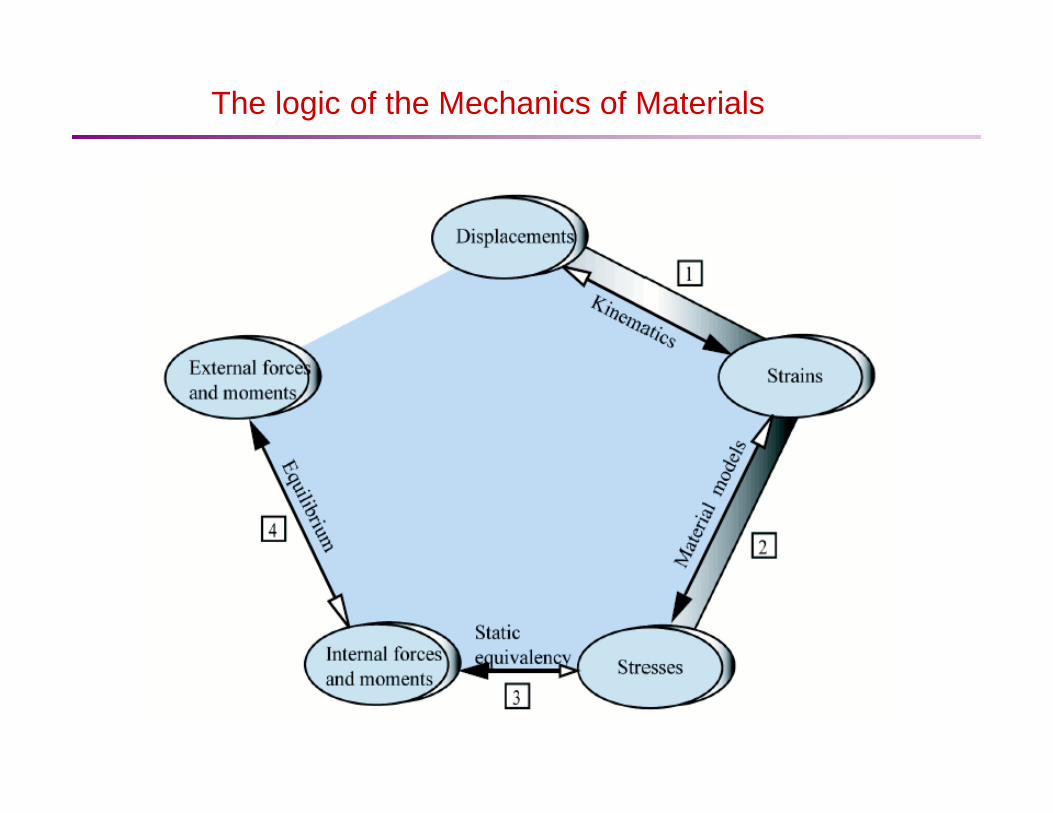
The logic of the Mechanics of Materials
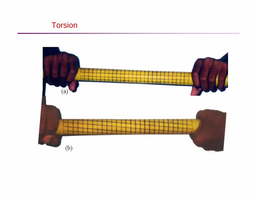
Torsion
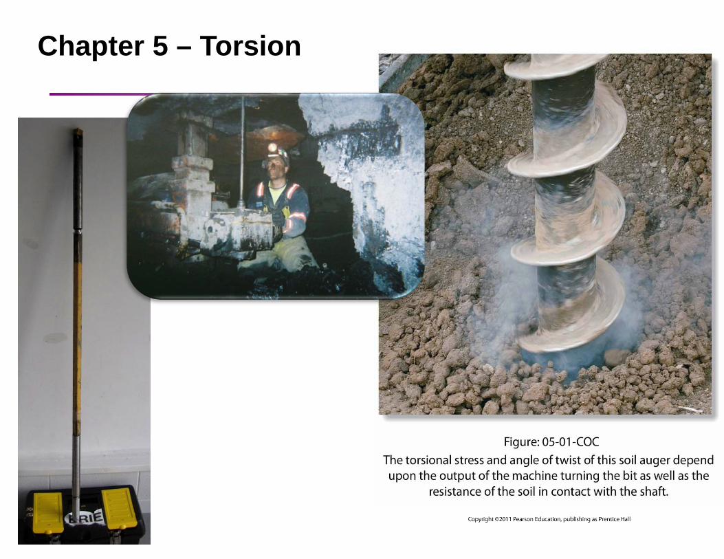
Chapter 5 – Torsion

Torsional failures (ductile, buckling, buckling):

Bars subjected to Torsion
Let us now consider a straight bar supported at one end and acted upon by two pairs of equal and opposite forces. Then each pair of forces and form a couple that tend to twist the bar about its longitudinal axis, thus producing surface tractions and moments. Then we can write the moments as
1P 2P
1 1 1T P d= 2 2 2T P d=
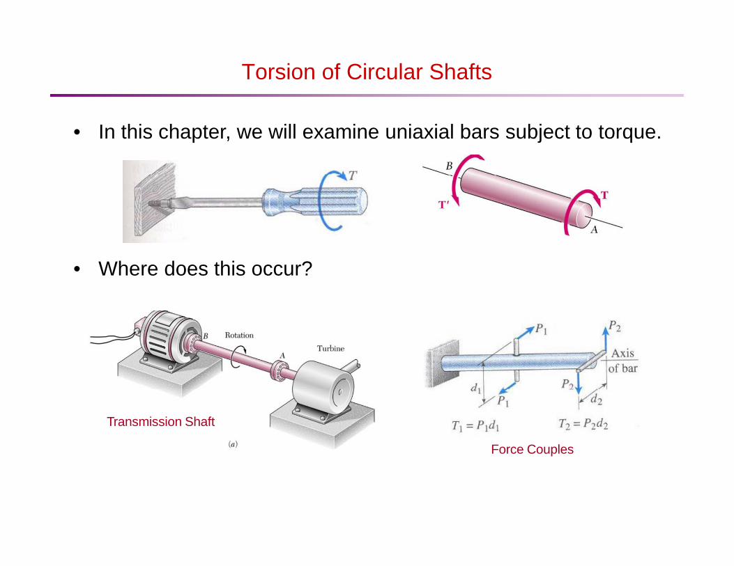
Torsion of Circular Shafts
• In this chapter, we will examine uniaxial bars subject to torque.
• Where does this occur?
Transmission Shaft
Force Couples
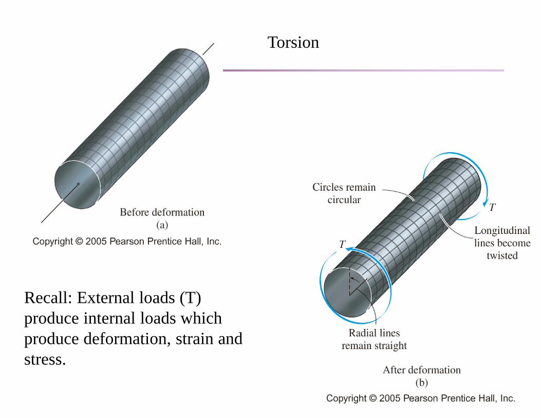
Torsion
Recall: External loads (T) produce internal loads which produce deformation, strain and stress.
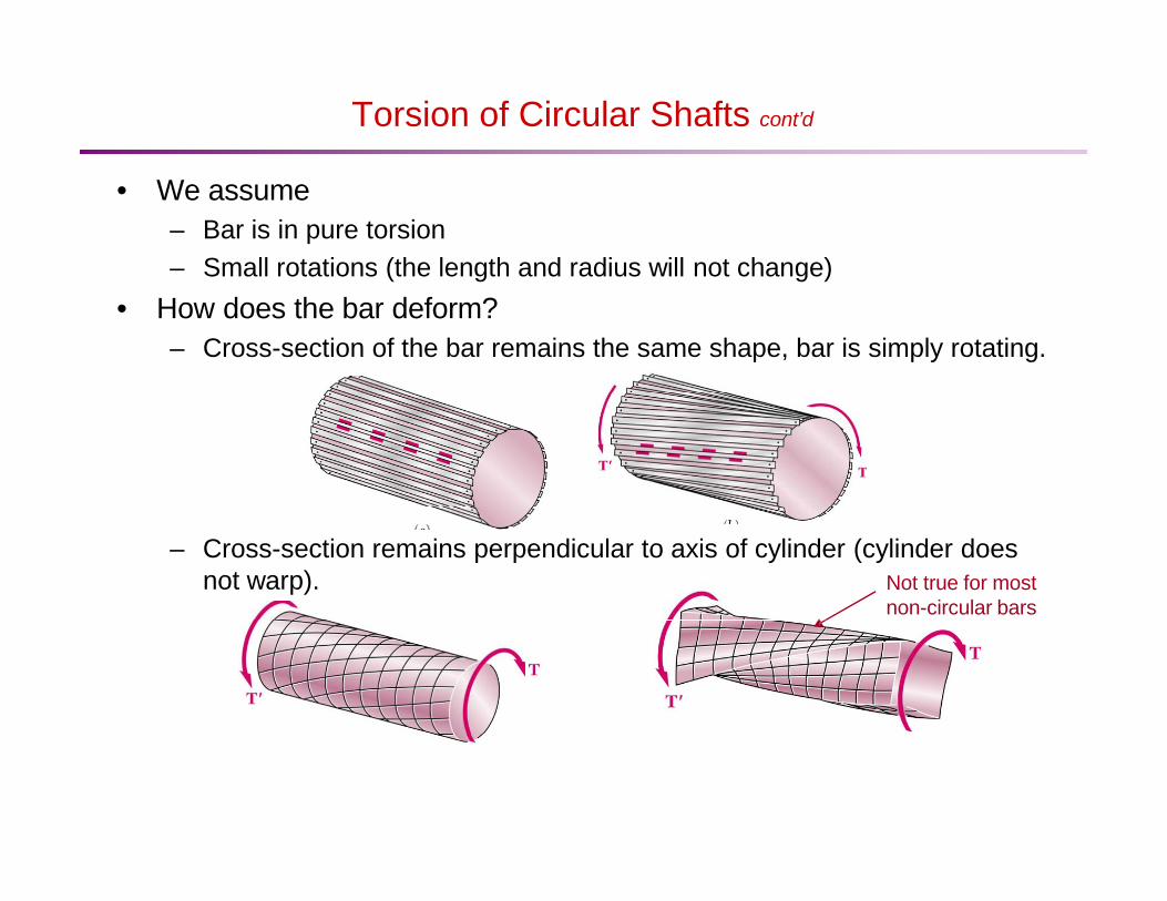
Torsion of Circular Shafts cont’d
• We assume – Bar is in pure torsion – Small rotations (the length and radius will not change)
• How does the bar deform? – Cross-section of the bar remains the same shape, bar is simply rotating.
– Cross-section remains perpendicular to axis of cylinder (cylinder does not warp). Not true for most
non-circular bars
Chapter 5: Torsion
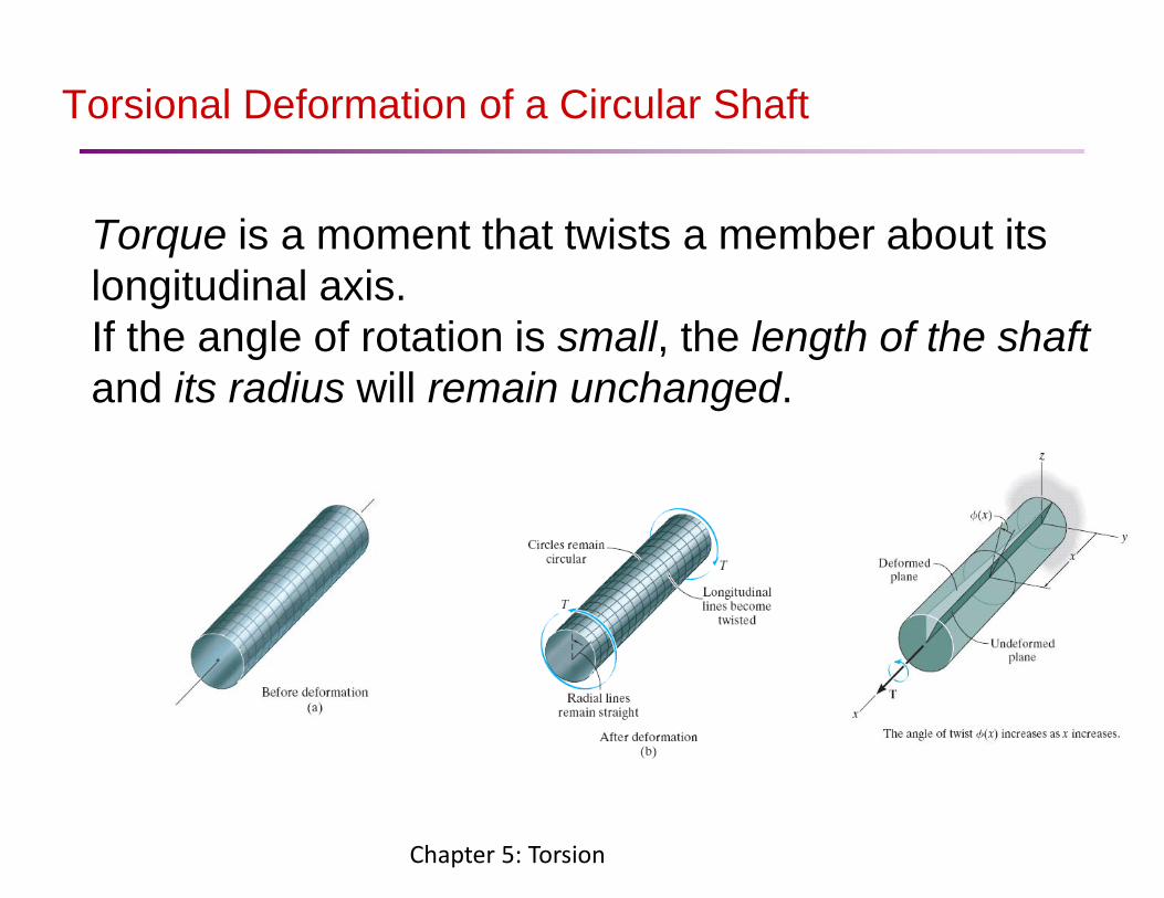
Torsional Deformation of a Circular Shaft
Torque is a moment that twists a member about its longitudinal axis. If the angle of rotation is small, the length of the shaft and its radius will remain unchanged.
’
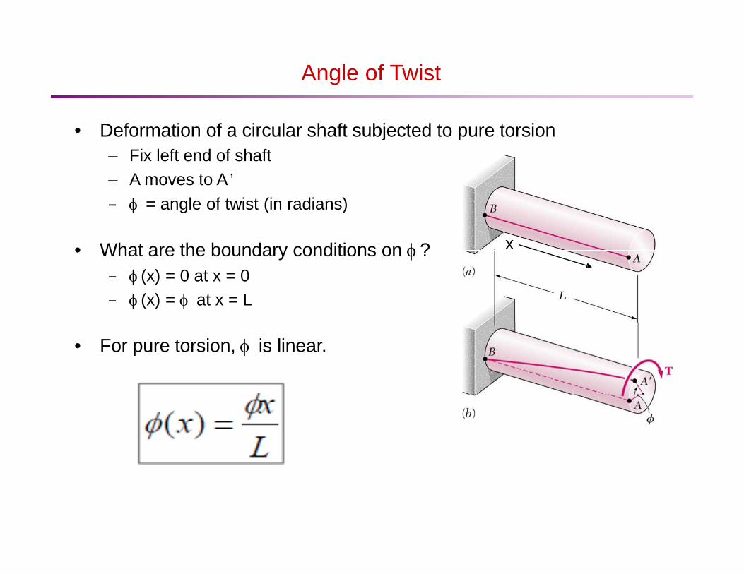
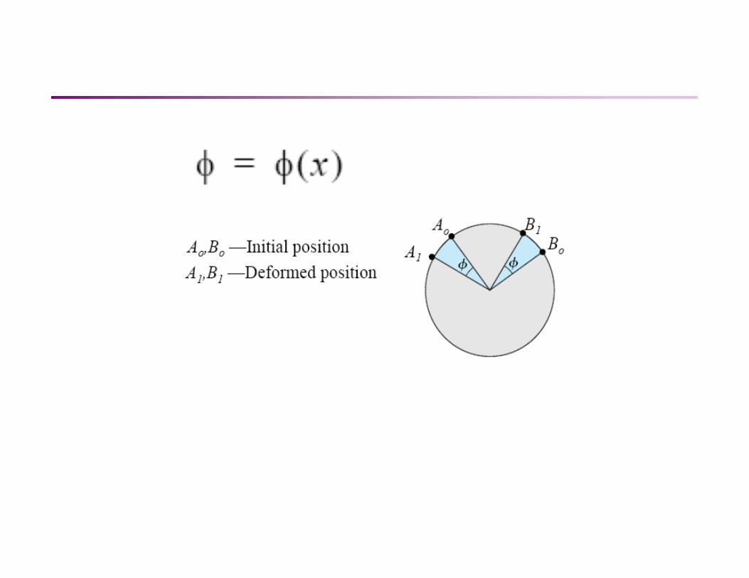
Angle of Twist • Deformation of a circular shaft subjected to pure torsion
– Fix left end of shaft – A moves to A – φ = angle of twist (in radians)
• What are the boundary conditions on φ ? x
– φ (x) = 0 at x = 0 – φ (x) = φ at x = L
• For pure torsion, φ is linear.

Shearing Strain • Calculate the surface shear strain in the
cylinder. • Consider an element of length dx. • Recall we assume small φ & small γ.
dx
• This equation applies to any function φ (x). • For pure torsion φ (x) = φ x / L, so
C’ C

Shearing Strain cont’d
Maximum shear strain on surface • The maximum shear strain on the surface of
the cylinder occurs when ρ=c.
• We can express the shearing strain at any distance from the axis of the shaft as
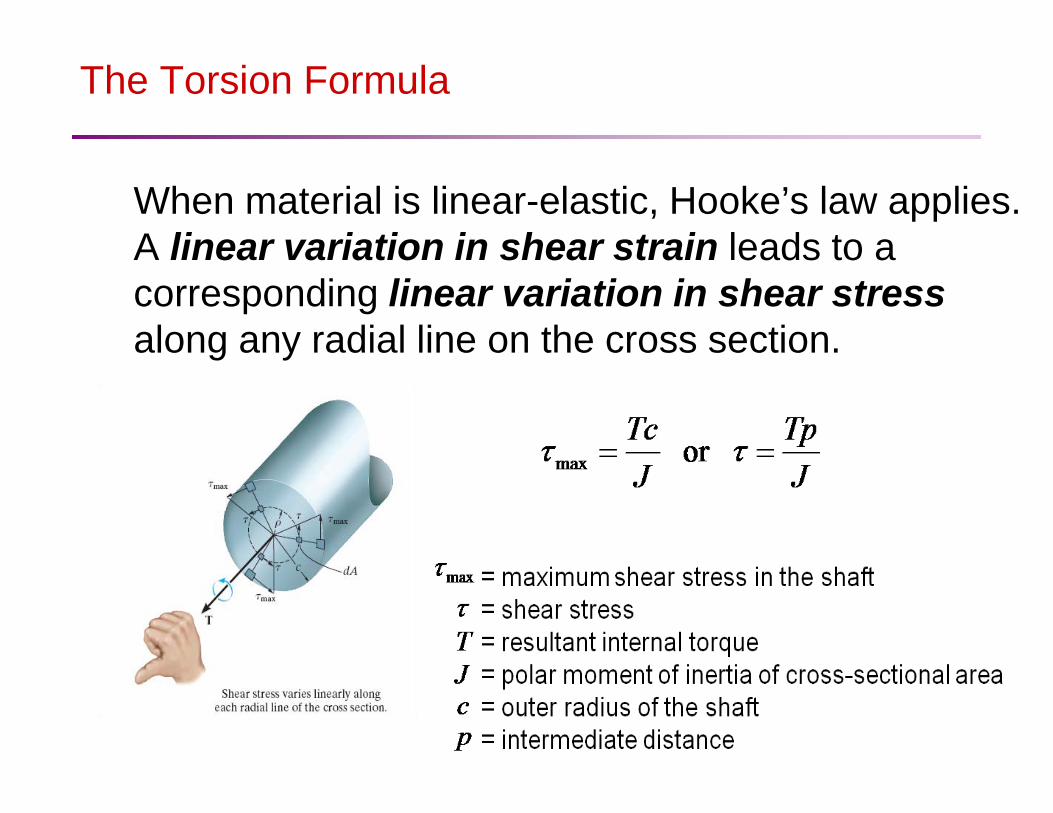
The Torsion Formula
When material is linear-elastic, Hooke’s law applies. A linear variation in shear strain leads to a corresponding linear variation in shear stress along any radial line on the cross section.

The Torsion Formula
If the shaft has a solid circular cross section, If a shaft has a tubular cross section,
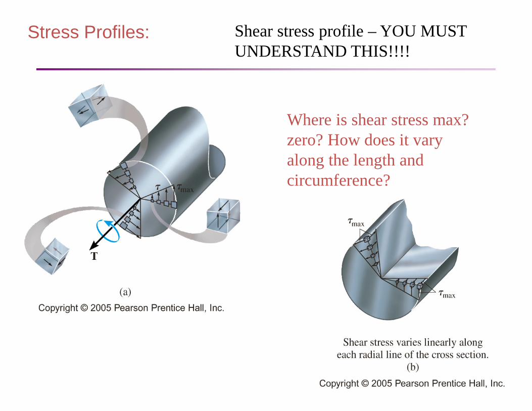
Shear stress profile – YOU MUST UNDERSTAND THIS!!!!
Where is shear stress max? zero? How does it vary along the length and circumference?
Stress Profiles:

Stress Profiles:

Shearing Strain cont’d
• We can also apply the equation for maximum surface shear strain to a hollow circular tube.
c c
• This applies for all types of materials: elastic, linear, non- linear, plastic, etc.
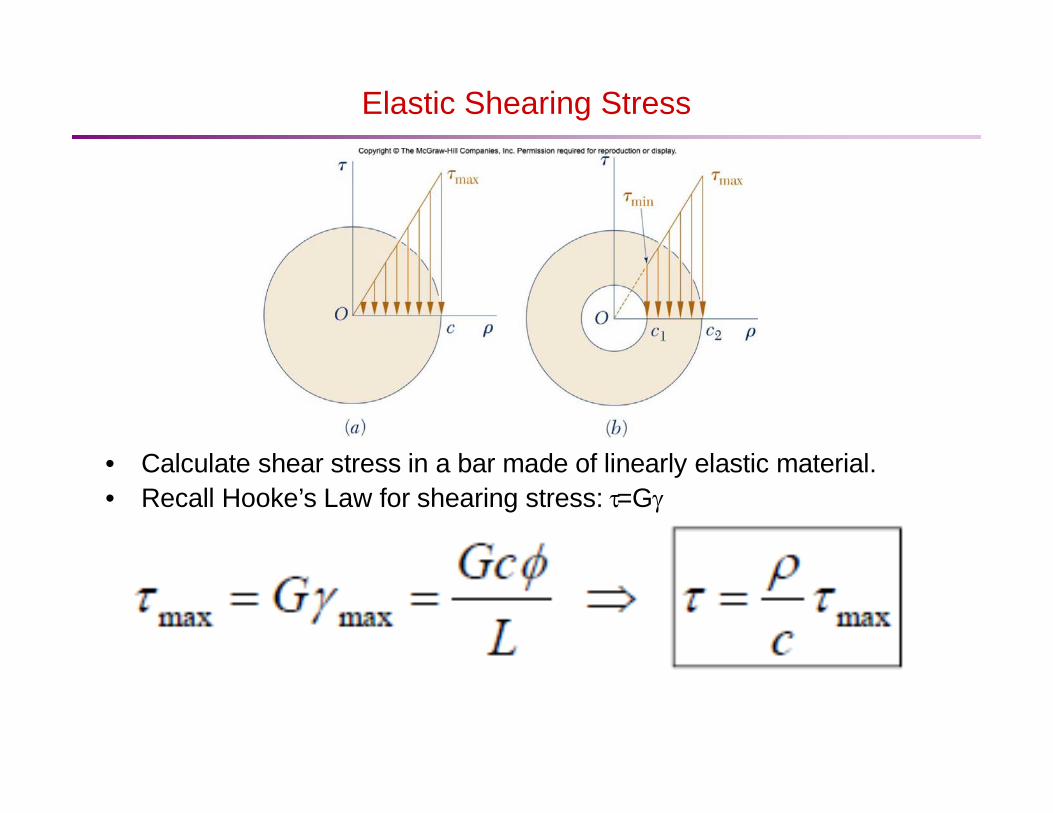
Elastic Shearing Stress
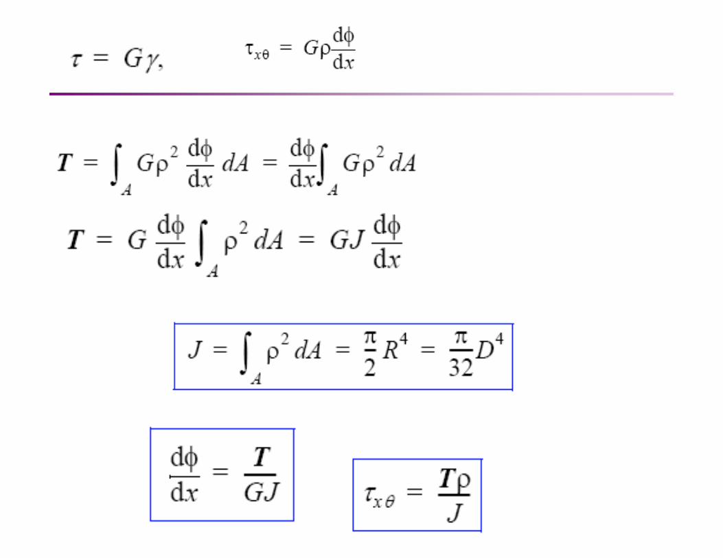
• Calculate shear stress in a bar made of linearly elastic material. • Recall Hooke’s Law for shearing stress: τ=Gγ
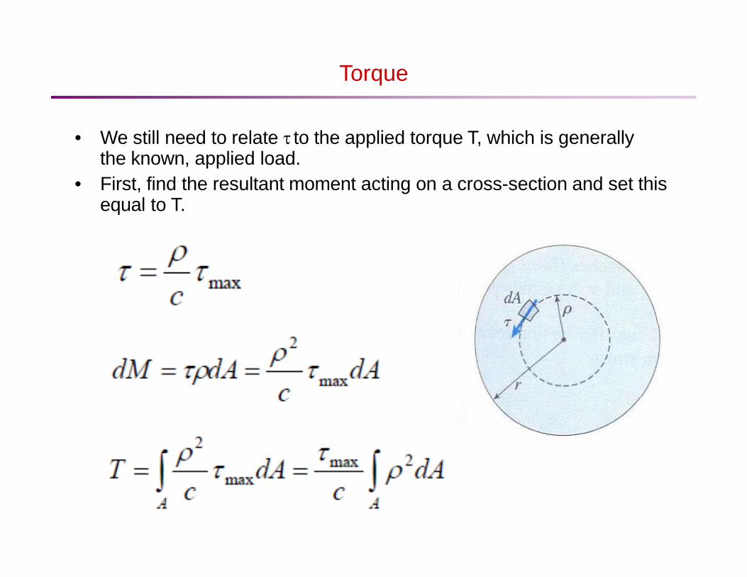
Torque • We still need to relate τ to the applied torque T, which is generally
the known, applied load. • First, find the resultant moment acting on a cross-section and set this
equal to T.
c
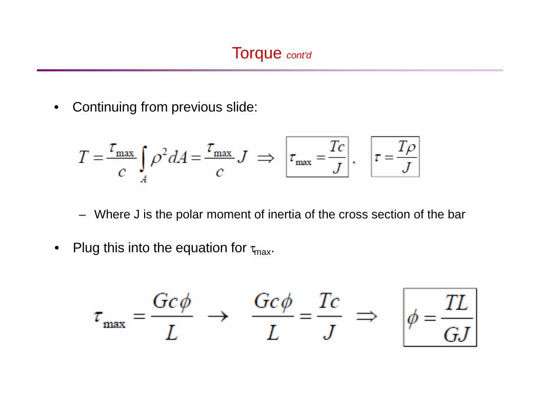
Torque cont’d • Continuing from previous slide:
– Where J is the polar moment of inertia of the cross section of the bar • Plug this into the equation for τmax.

Torque cont’d • For a non-uniform bar
φ = ∑ φ = ∑ Ti Li n n
i
• For a continuously varying bar
=1 G J i=1 i i i

Inclined Plane
• Cut a rectangular element along the plane at an angle θ.
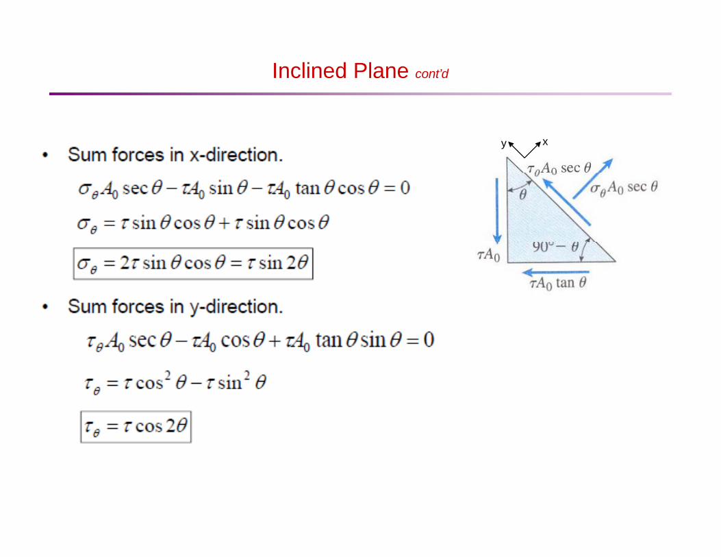
Inclined Plane cont’d
y x
Inclined Plane cont’d
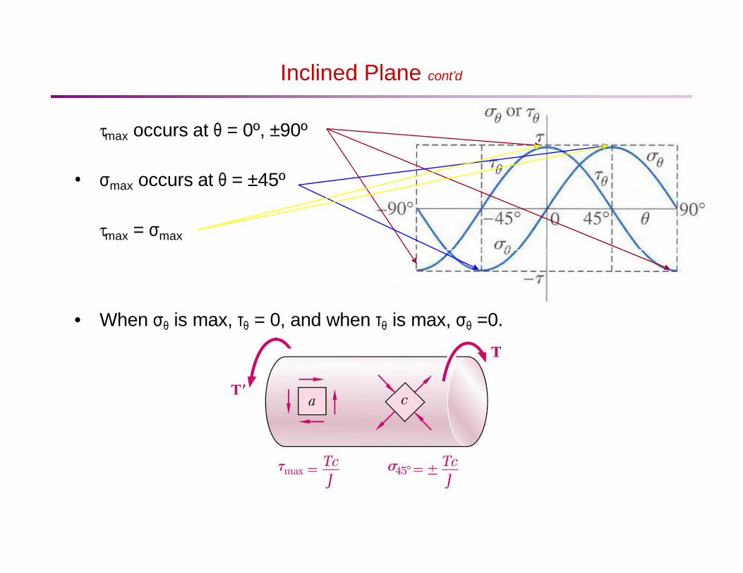
τmax occurs at θ = 0º, ±90º • σmax occurs at θ = ±45º
τmax = σmax
• When σθ is max, τθ = 0, and when τθ is max, σθ =0.
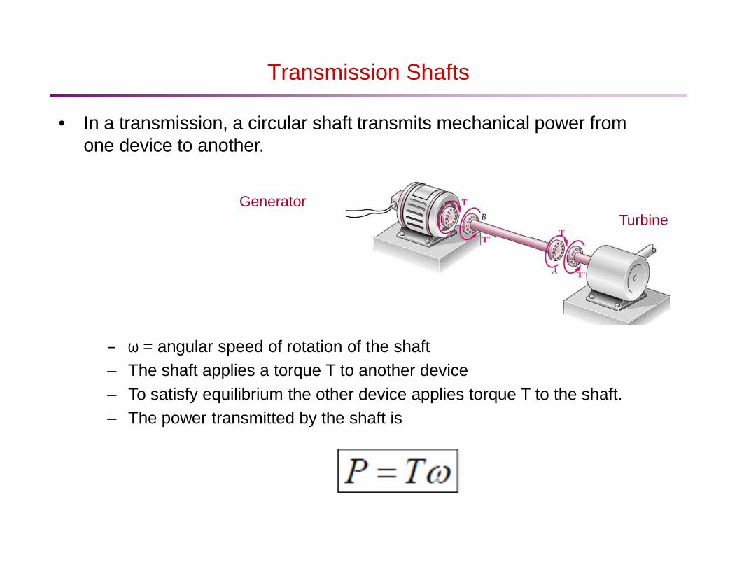
Transmission Shafts
• In a transmission, a circular shaft transmits mechanical power from one device to another.
Generator
– ω = angular speed of rotation of the shaft – The shaft applies a torque T to another device – To satisfy equilibrium the other device applies torque T to the shaft. – The power transmitted by the shaft is
Turbine
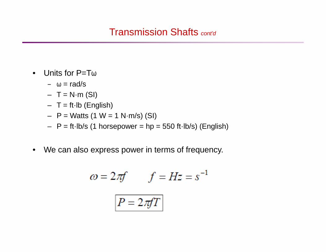
Transmission Shafts cont’d
• Units for P=Tω – ω = rad/s – T = N·m (SI) – T = ft·lb (English) – P = Watts (1 W = 1 N·m/s) (SI) – P = ft·lb/s (1 horsepower = hp = 550 ft·lb/s) (English)
• We can also express power in terms of frequency.

Stress Concentrations in Circular Shafts
• Up to now, we assumed that transmission shafts are loaded at the ends through solidly attached, rigid end plates.
• In practice, torques are applied through flange couplings and fitted keyways, which produce high stress concentrations.
Fitted keyway
Flange coupling • One way to reduce stress concentrations is through the use of a
fillet.

Stress Concentrations in Circular Shafts cont’d • Maximum shear stress at the fillet
Fillet – Tc/J is calculated for the smaller-diameter shaft – K = stress concentration factor
J = K Tc
max τ
Στρέψη – περιορισμοί για άξονες κυκλικής διατομής
• Το μήκος του μέλους που υπόκειται σε στρέψη είναι σημαντικά
μεγαλύτερο από τη μεγαλύτερη διάσταση της διατομής.
• Η περιοχή που εξετάζεται δεν περιέχει συγκεντρώσεις τάσεων.
• Η μεταβολή της εξωτερικής στρέψης ή η μεταβολή των εμβαδών των
διατομών είναι βαθμιαία, με εξαίρεση τις περιοχές συγκέντρωσης
τάσεων.
• ΟΙ εξωτερικές στρεπτικές ροπές δεν εξαρτώνται από το χρόνο, το
πρόβλημα είναι στατικό.
• Η διατομή είναι κυκλική, επιτρέποντας τη χρήση της συμμετρίας ως
προς τον άξονα για τη μείωση της παραμόρφωσης.
Στρέψη - Παραδοχές
1. Τα επίπεδα τμήματα που είναι κάθετα στον άξονα περιστροφής παραμένουν επίπεδα κατά τη διάρκεια της παραμόρφωσης.
2. Σε μια διατομή, όλες οι ακτινικές γραμμές περιστρέφονται κατά ίσες γωνίες κατά τη διάρκεια της παραμόρφωσης.
3. Οι ακτινικές γραμμές παραμένουν ευθείες κατά τη διάρκεια της παραμόρφωσης.
4. Οι παραμορφώσεις είναι μικρές. 5. Το υλικό είναι γραμμικά ελαστικό. 6. Το υλικό είναι ισότροπο. 7. Το υλικό είναι ομογενές κατά μήκος της περιοχής της διατομής.

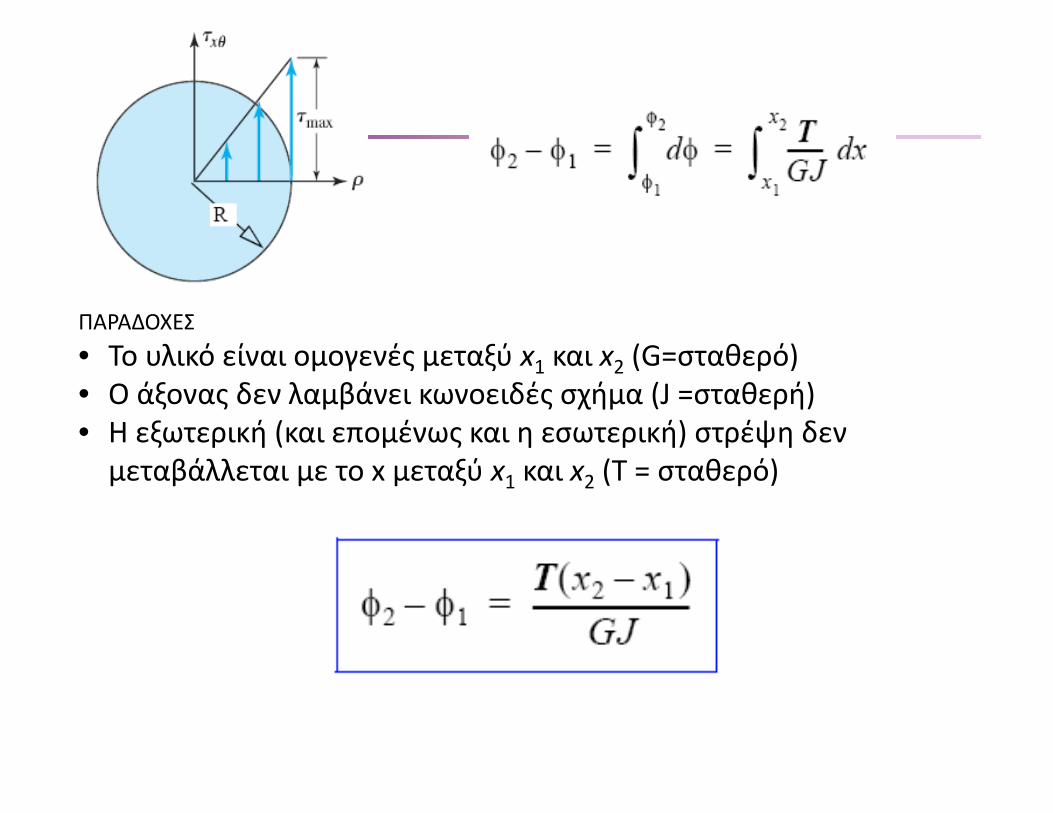
ΠΑΡΑΔΟΧΕΣ • Το υλικό είναι ομογενές μεταξύ x1 και x2 (G=σταθερό) • Ο άξονας δεν λαμβάνει κωνοειδές σχήμα (J =σταθερή) • Η εξωτερική (και επομένως και η εσωτερική) στρέψη δεν
μεταβάλλεται με το x μεταξύ x1 και x2 (T = σταθερό)
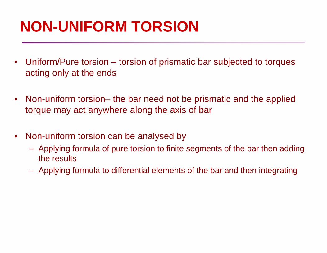
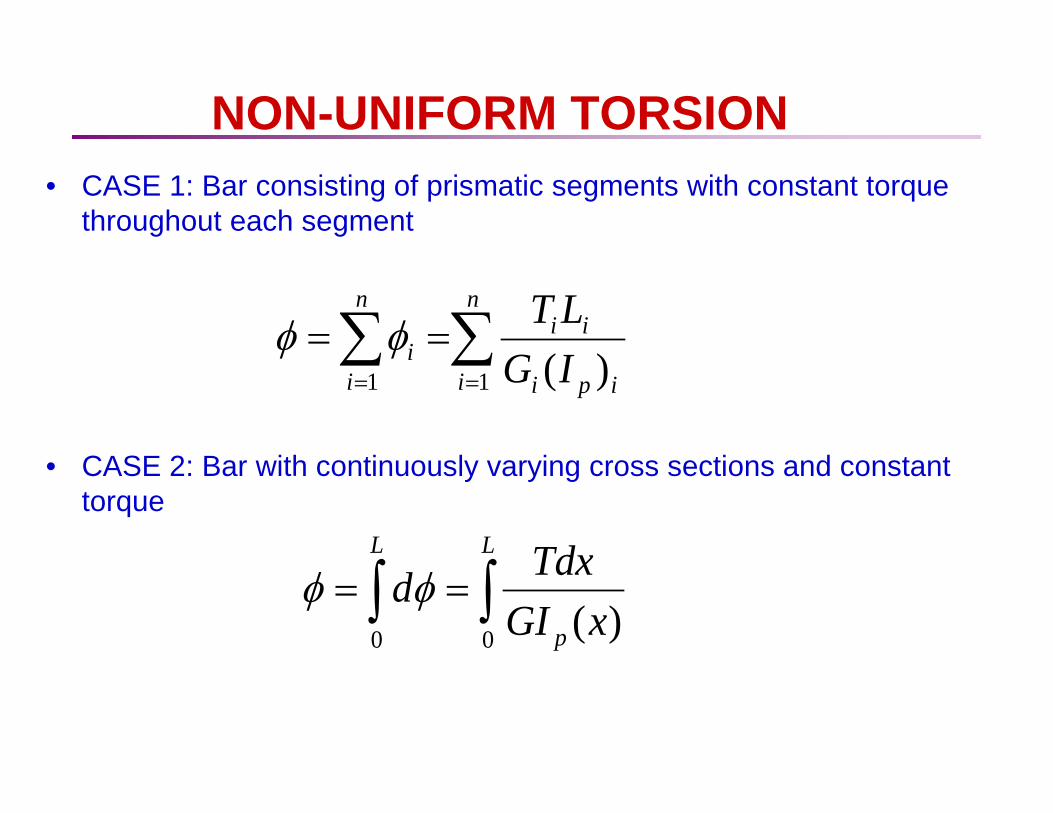
NON-UNIFORM TORSION
• Uniform/Pure torsion – torsion of prismatic bar subjected to torques acting only at the ends
• Non-uniform torsion– the bar need not be prismatic and the applied
torque may act anywhere along the axis of bar
• Non-uniform torsion can be analysed by – Applying formula of pure torsion to finite segments of the bar then adding
the results – Applying formula to differential elements of the bar and then integrating
NON-UNIFORM TORSION
∑∑==
==n
i ipi
iin
ii IG
LT11 )(
φφ
• CASE 1: Bar consisting of prismatic segments with constant torque throughout each segment
• CASE 2: Bar with continuously varying cross sections and constant torque
∫∫ ==L
p
L
xGITdxd
00 )(φφ

NON-UNIFORM TORSION
• CASE 3: Bar with continuously varying cross sections and continuously varying torque
∫∫ ==L
p
L
xGIdxxTd
00 )()(φφ
NON-UNIFORM TORSION
• Limitations – Analyses described valid for bar made of linearly elastic materials – Circular cross sections (Solid /hollow)
• Stresses determined from the torsion formula valid in region of the bar away from stress concentrations (diameter changes abruptly/concentrated torque applied – For the case above, Angle of twist still valid – Changes in diameter is are small and gradually (angle of taper max 10o)

SOLID NON-CIRCULAR SHAFTS
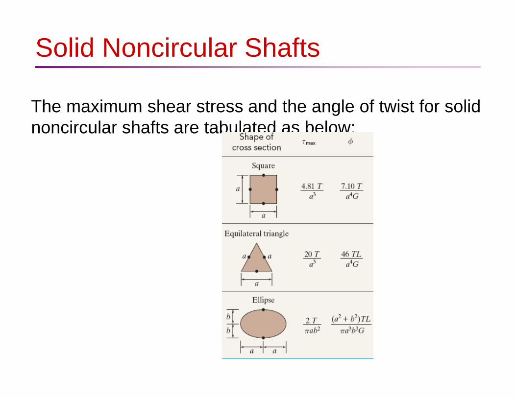
Solid Noncircular Shafts
The maximum shear stress and the angle of twist for solid noncircular shafts are tabulated as below:
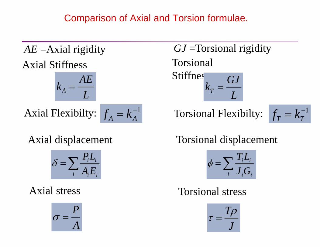
Comparison of Axial and Torsion formulae.
AE =Axial rigidity Axial Stiffness
Axial Flexibilty:
GJ =Torsional rigidity Torsional Stiffness
Torsional Flexibilty:
LAEkA =
1−= AA kfL
GJkT =
1−= TT kf
Axial displacement
∑=i ii
ii
GJLTφ∑=
i ii
ii
EALPδ
Torsional displacement
Axial stress
AP
=σJ
Tρτ =
Torsional stress
Sample Problem 1
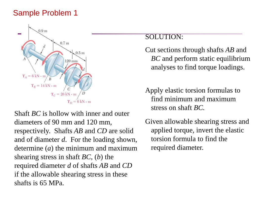
Shaft BC is hollow with inner and outer diameters of 90 mm and 120 mm, respectively. Shafts AB and CD are solid and of diameter d. For the loading shown, determine (a) the minimum and maximum shearing stress in shaft BC, (b) the required diameter d of shafts AB and CD if the allowable shearing stress in these shafts is 65 MPa.
SOLUTION:
Cut sections through shafts AB and BC and perform static equilibrium analyses to find torque loadings.
Given allowable shearing stress and applied torque, invert the elastic torsion formula to find the required diameter.
Apply elastic torsion formulas to find minimum and maximum stress on shaft BC.

Sample Problem 1 SOLUTION: Cut sections through shafts AB and BC
and perform static equilibrium analysis to find torque loadings.
( )
CDAB
ABx
TT
TM
=⋅=
−⋅==∑mkN6
mkN60 ( ) ( )mkN20
mkN14mkN60
⋅=
−⋅+⋅==∑
BC
BCx
T
TM
Fig. 1 Free-body diagram for section between A and B. Fig. 2 Free-body diagram for section between B and C.
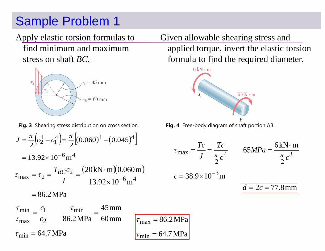
Sample Problem 1 Apply elastic torsion formulas to
find minimum and maximum stress on shaft BC.
( ) ( ) ( )[ ]46
4441
42
m1092.13
045.0060.022
−×=
−=−=ππ ccJ
( )( )
MPa2.86m1092.13
m060.0mkN2046
22max
=
×
⋅=== −J
cTBCττ
MPa7.64
mm60mm45
MPa2.86
min
min
2
1
max
min
=
==
τ
τττ
cc
MPa7.64
MPa2.86
min
max
=
=
τ
τ
Given allowable shearing stress and applied torque, invert the elastic torsion formula to find the required diameter.
m109.38
mkN665
3
32
42
max
−×=
⋅===
c
cMPa
cTc
JTc
ππτ
mm8.772 == cd
Fig. 3 Shearing stress distribution on cross section. Fig. 4 Free-body diagram of shaft portion AB.

Statically Indeterminate Shafts Given the shaft dimensions and the applied torque,
we would like to find the torque reactions at A and B.
From a free-body analysis of the shaft, which is not sufficient to find the end torques. The problem is statically indeterminate.
ftlb90 ⋅=+ BA TT
ftlb9012
21 ⋅=+ AA TJLJLT
Substitute into the original equilibrium equation,
ABBA T
JLJLT
GJLT
GJLT
12
21
2
2
1
121 0 ==−=+= φφφ
Divide the shaft into two components which must have compatible deformations,
(a) Shaft with central applied torque and fixed ends. (b) free-body diagram of shaft AB. (c) Free-body diagrams for solid and hollow segments.
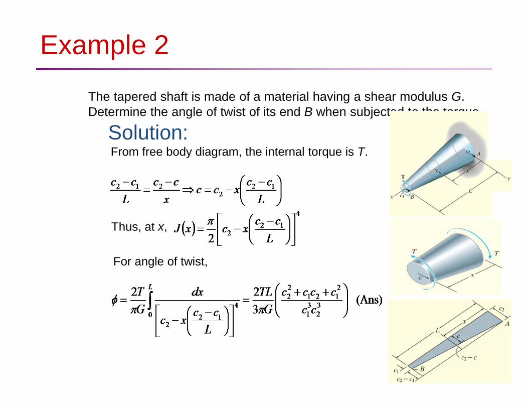
Example 2 The tapered shaft is made of a material having a shear modulus G. Determine the angle of twist of its end B when subjected to the torque.
Solution: From free body diagram, the internal torque is T.
Thus, at x,
For angle of twist,
STATICALLY INDETERMINATE TORQUE-LOADED MEMBERS
Procedure for analysis: use both equilibrium and compatibility equations
Equilibrium Draw a free-body diagram of the shaft in order to identify
all the torques that act on it. Then write the equations of moment equilibrium about the axis of the shaft.
Compatibility To write the compatibility equation, investigate the way
the shaft will twist when subjected to the external loads, and give consideration as to how the supports constrain the shaft when it is twisted.

STATICALLY INDETERMINATE TORQUE-LOADED MEMBERS (cont)
Express the compatibility condition in terms of the rotational displacements caused by the reactive torques, and then use a torque-displacement relation, such as Φ = TL/JG, to relate the unknown torques to the unknown displacements.
Solve the equilibrium and compatibility equations for the
unknown reactive torques. If any of the magnitudes have a negative numerical value, it indicates that this torque acts in the opposite sense of direction to that indicated on the free-body diagram.
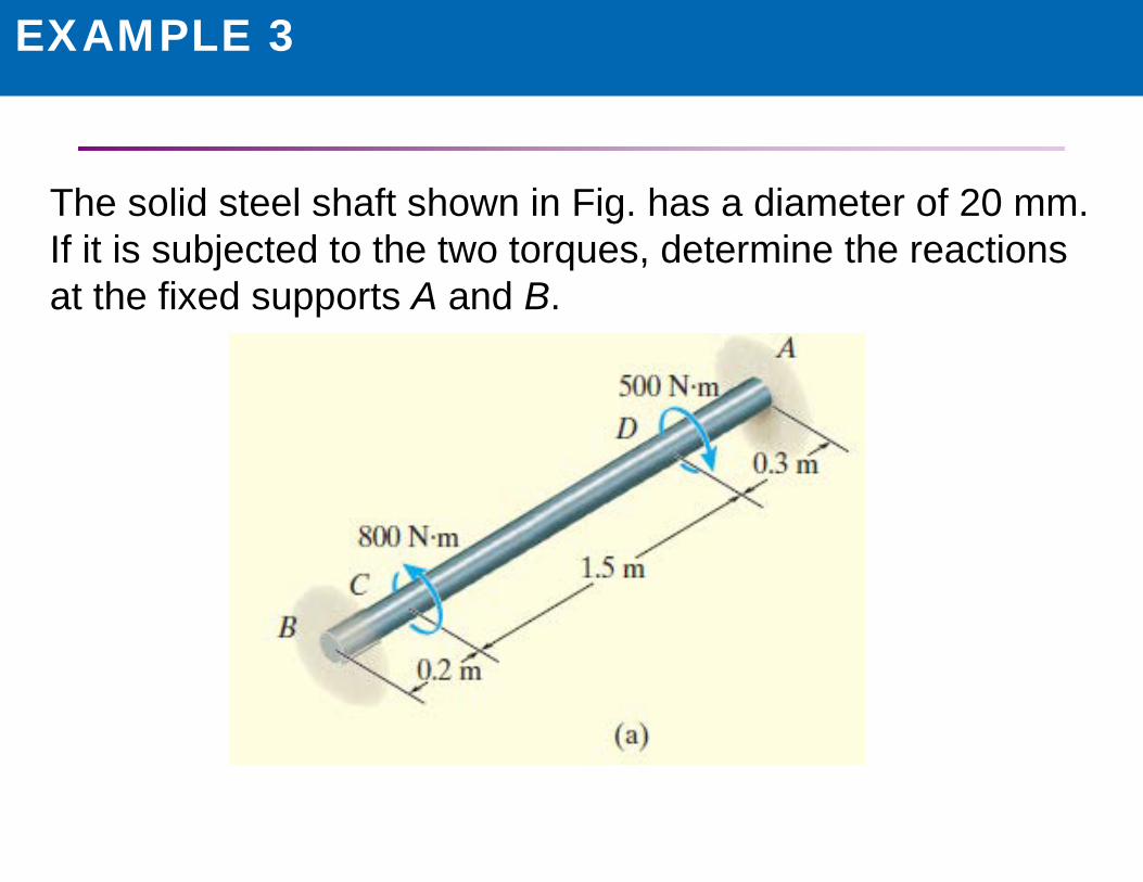
EXAMPLE 3
The solid steel shaft shown in Fig. has a diameter of 20 mm. If it is subjected to the two torques, determine the reactions at the fixed supports A and B.
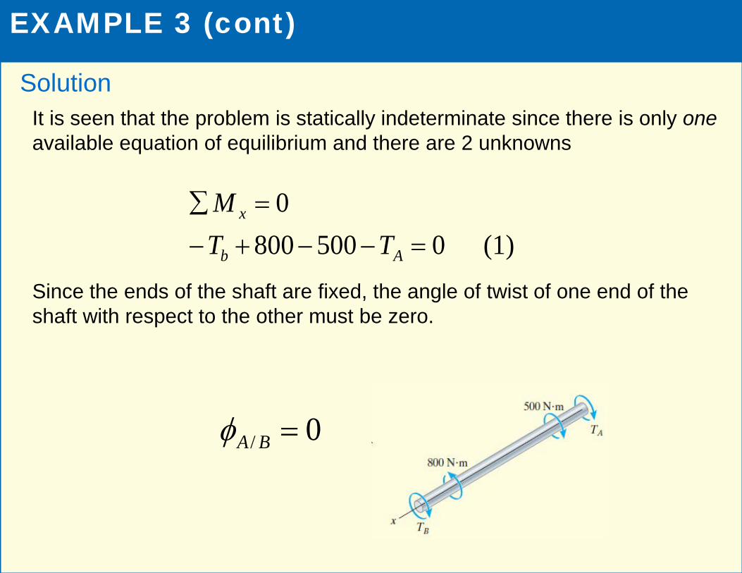
EXAMPLE 3 (cont)
It is seen that the problem is statically indeterminate since there is only one available equation of equilibrium and there are 2 unknowns Since the ends of the shaft are fixed, the angle of twist of one end of the shaft with respect to the other must be zero.
Solution
(1) 05008000
=−−+−=∑
Ab
x
TTM
0/ =BAφ

EXAMPLE 3 (cont)
Using the sign convention established, Using Eq. 1, The negative sign indicates that acts in the opposite direction of that shown in Fig. (b)
Solution
( ) ( )( ) ( )( )
(Ans) mN 645
03.03005.18002.0
⋅=
=−
+−
+−
B
BBB
TJGT
JGT
JGT
mN 345 ⋅−=AT


