Download - Title Slide Layout (Maximum 2 Lines)

Joe Lin 2021/03/25
Project Manager / Keysight Technologies

2
• Introduction
• Polarization Resolved Spectral Measurements
• High-Frequency Testing
• Summary / Q&A
矽光子集成之晶圓級光電量測挑戰

33
I N T E G R AT E D P H O T O N I C S
矽光子集成之晶圓級光電量測挑戰

4
Motivations for photonic integrated circuits (PICs):
• Integration of different functions: waveguides, polarization
components, lasers, modulators, switches, optical amplifiers,
and detectors
• Higher data rates, lower power consumption, lower $/Gbps,
high reliability
• Need PICs when:
• VCSELs become limited in bandwidth and distance
• WDM and single mode fiber transmission is required
• The number of optical ports is increasing
• Optics and electronics ICs are closer to each other
• Data rates increase (400G, 800G, and more)
• There is a need for embedded modules
• Improved reliability is required
矽光子集成之晶圓級光電量測挑戰

5矽光子集成之晶圓級光電量測挑戰

6
A new level of complexity:
• Photonic ICs are highly polarization dependent
• Photonic ICs can have a lot of electronic connections in addition to optics
• Probing can get busy, fast, and complex/error prone especially when RF
comes into play
• Common questions:
1. What instruments should I use?
2. How to optimize for speed?
3. How to deal with polarization?
4. How to obtain dynamic range in filters with deep rejection?
5. What is the best approach for PDL measurements?
6. How to measure photodetectors and lasers?
Both DC and high-frequency
矽光子集成之晶圓級光電量測挑戰

77
C H A L L E N G E S A N D S O L U T I O N S
矽光子集成之晶圓級光電量測挑戰

8
L I G H T T R A N S M I S S I O N I N O P T I C A L F I B E R
Polarization Maintaining Fiber Single Mode Fiber
Poincare Sphere
LHP
LVP
RCP
LCP
Input
SOP
Output
SOP
矽光子集成之晶圓級光電量測挑戰

9
T E / T M A N A LY S I S W I T H I L / P D L S O L U T I O N
Keywords: “integrated photonics”,
“silicon photonics”, “planar lightwave
circuits (PLC)”, “photonic integrated
circuits (PIC)”• Planar devices on wafers, bars, and chips
• Often desired or undesired difference for E-
field polarization in-plane TE or out-of-plane
TM
• Measurement is often still made by aligning
polarization in a search and optimize process
and then measuring
• Slow and the polarization changes as
the wavelength is swept
Measurement Challenges• Probe station alignment
• Polarization resolved measurements
• Wavelength resolved measurements
• Fast measurement throughput
矽光子集成之晶圓級光電量測挑戰

10
F O R M FA C T O R C M 3 0 0 X I - S I P H A U T O M AT E D WA F E R L E V E L S O L U T I O N F O R P H O T O N I C S
Exclusive Automated Calibration of
Positioning Solution to the Probe Station
Automated High Speed Optical
Alignments/Optimizations
Verifiable Coupled Power Repeatability of
<0.3dB矽光子集成之晶圓級光電量測挑戰

11
I N S T R U M E N T B U I L D I N G B L O C K S F O R O P T I C A L A N D D C E L E C T R I C A L T E S T
Polarization Control / Polarization Analysis
DU
T
Tunable Lasers O S C L Band Optical Power Meters
Source Measurement Unit
矽光子集成之晶圓級光電量測挑戰

12
T U N A B L E L A S E R A N D P O W E R M E T E R – S W E P T I N S E R T I O N L O S S ( I L )
Agilent Restricted
Po
we
r
Po
we
r
TLS performs a continuous sweep at constant velocity (i.e. 40 nm/s)
PM’s take samples at regular intervals (i.e. every 0.001 nm = 40,000 samples/s)
TunableLaser Source(TLS)
PowerMeter(s)DeviceDevice
Insertion Loss (dB)
10*log(Pin/Pout)
Pin Pout
Photonic Application Suite
N7700102C Software Engine
N777xC
Tunable Laser
N774xC
Power Meter
LAN or
USBLAN or
USB
PIC DUT
trigger cable
矽光子集成之晶圓級光電量測挑戰

13
T H E N E E D F O R P O L A R I Z AT I O N A L I G N M E N T
TunableLaser Source
PowerMeter
High
PER
Device
Po
we
r
PM’s take samples at regular intervals (i.e. every 0.002nm = 5000 samples/s)
TLS performs a continuous sweep at constant velocity (i.e. 10nm/s)
Min Loss vs. Wavelength @ various input SOP
PER = Polarization Extinction Ratio
矽光子集成之晶圓級光電量測挑戰

14
P O L A R I Z AT I O N M A I N TA I N I N G ( P M ) F I B E R
PM FiberTunableLaser Source
PowerMeter
~ 0.3 dB
High
PER
Device
PM fiber slow axis aligned to polarizer
Limited extinction between fast and slow axis causes ripple
矽光子集成之晶圓級光電量測挑戰

15
P O L A R I Z AT I O N S C A N N I N G – S E A R C H F O R P M A X AT
• ~ 2 to 5 seconds measurement time per
• Best for single / few s
• High accuracy
• Simple to implement
Random scanning
of polarization states
Polarization Controller
TunableLaser Source
PowerMeter
SOP for Pmin
SOP for Pmax
High
PER
Device
-3 dB Power
Input Power
Insertion Loss Pmax
States of Polarization
Output Power
SamplesPmin
Polarization Analysis
矽光子集成之晶圓級光電量測挑戰

16
P O L A R I Z AT I O N S C A N N I N G – S E A R C H F O R P M A X AT
1k point sequence
~ 1.5 seconds
10k point sequence
~ 4.5 seconds
矽光子集成之晶圓級光電量測挑戰

17
P O L A R I Z AT I O N S C A N N I N G – S E T S O P F O R P M A X AT
Polarization Controller
TunableLaser Source
PowerMeter
High
PER
Device
Polarization Analysis
_start _stop
SOP @ _stop
SOP @ _start
SOP for Pmax at
for Pmax
矽光子集成之晶圓級光電量測挑戰

18
M U E L L E R M AT R I X - S W E P T I L / P D L
Insertion Loss / Polarization Dependent Loss / TE – TM Loss
Control PC
Tunable Laser
Polarization
Controller / AnalysisPower
Meter
i) Reference Path
ii) Device Path
DeM
ux
un
de
r Te
st
Photonic Application Suite
N7700100C Software Engine
N7786C
Polarization
Controller
N774xC
Power Meter
LAN or
USBLAN or
USB
PIC DUT
trigger cable
N777xC
Tunable Laser
LAN or
USB
矽光子集成之晶圓級光電量測挑戰
19
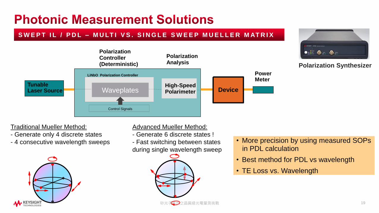
S W E P T I L / P D L – M U LT I V S . S I N G L E S W E E P M U E L L E R M AT R I X
Traditional Mueller Method:
- Generate only 4 discrete states
- 4 consecutive wavelength sweeps • More precision by using measured SOPsin PDL calculation
• Best method for PDL vs wavelength
• TE Loss vs. Wavelength
Advanced Mueller Method:
- Generate 6 discrete states !
- Fast switching between states
during single wavelength sweep
Polarization Synthesizer
Polarization Controller(Deterministic)
PowerMeter
Device
Control Signals
LiNbO Polarization Controller
High-Speed Polarimeter
Polarization Analysis
TunableLaser Source Waveplates
矽光子集成之晶圓級光電量測挑戰

20
M U E L L E R M AT R I X – S TA N D A R D PA S S I V E O P T I C A L C O M P O N E N T W / L O W P D L
Average Insertion Loss
TE / TM Loss
Polarization Dependent Loss
Polarization Controller
TunableLaser Source
PowerMeter
Device
Polarization Analysis
矽光子集成之晶圓級光電量測挑戰

21
M U E L L E R M AT R I X – PA S S I V E O P T I C A L C O M P O N E N T W / M E D I U M P D L
TE / TM Loss
Polarization Dependent LossPolarization Controller
TunableLaser Source
PowerMeter
Device
Polarization Analysis
矽光子集成之晶圓級光電量測挑戰

22
M U E L L E R M AT R I X – H I G H P E R PA S S I V E O P T I C A L C O M P O N E N T
Polarizer at Positions0 / 45 / 90 / 135 / 180 degree
TE Loss
TM Loss
• Matrix analysis for IL in principle axes (TE Loss)
• No Polarization Alignment steps
• Mueller Matrix only able to resolve < 20 dB PDL
~ 20 dB
Polarization Controller
TunableLaser Source
PowerMeter
Device
Polarization Analysis
矽光子集成之晶圓級光電量測挑戰

23
A L L S TAT E S – WAV E L E N G T H S E L E C T I V E P E R M E A S U R E M E N T S
Input Power
Insertion
Loss
PDL
States of Polarization
Output Power
Samples
• ~ 2 to 5 seconds measurement time per
• Best for single / few ’s
• High accuracy
• Simple to implement
• Large Dynamic Range ~ 35 dB
Random scanning
of polarization states
Polarization Dependent Loss
PDL = 10*log(Pout_max/Pout_min)
Polarization Controller
TunableLaser Source
PowerMeter
Device
矽光子集成之晶圓級光電量測挑戰

24
C O M P O N E N T S W I T H I N T E G R AT E D O P T I C A L D E T E C T O R S
• Replace power meters with source/measure
units to detect photocurrent for responsivity test
• Spectra for IL and pol.-averaged IL
• Matrix analysis for IL in principal axes (TE/TM)
without polarization alignment steps
• CMRR for balanced ports
Control PC
B2900A Series Source/
Measure Units
N7745C Multiport
Power Meter
N7786C Polarization
Synthesizer
PIC
DU
T
N7776C Tunable Laser Source
CWDM receiver
矽光子集成之晶圓級光電量測挑戰

2525
M O D U L AT O R S A N D D E T E C T O R S O N - W A F E R
矽光子集成之晶圓級光電量測挑戰

26
L C A = V N A + C A L I B R AT E D O P T I C A L F R O N T E N D
Mixed stimulus-response:
Wavelength: 0.85, 1.3, 1.5 mm
LCA measures
photodetectors/
receivers and
lasers/modulators
Lightwave Component Analyzer (LCA) Modes of Operation
O-O: Optical-OpticalE-E: S-Parameters
E-O: Modulator and Laser testO-E: Photodetector test
矽光子集成之晶圓級光電量測挑戰

27
P H O T O D I O D E O N WA F E R / C H I P L E V E L
• Four LCA measurement modes:
• OO, OE, EO and EE with one instrument
• 1310/1550 nm or 1290 to 1610 nm with external laser,
850 nm with MMF
• Balanced port measurements with 4-port network analyzer
options
Polarization alignment of LCA stimulus signal to DUT
needed:
• Done in combination with the IL/PDL setup and
static mode or using PMF to DUT.
Optical
De-embed RF probe & optical probe
Optical
Lightwave Component Analyzer
矽光子集成之晶圓級光電量測挑戰

28
G E T T I N G R F T O D U T A S C L O S E A S P O S S I B L E
mmW
Extender
Module
Optical
Transmitter
Optical
Receiver
mmW
Extender
Module
Wafer Probes
Extender mounts10 cm straight
cables
矽光子集成之晶圓級光電量測挑戰

29
T R A N S F E R R I N G C A L I B R AT I O N P L A N E F R O M C O A X I A L T O C O - P L A N A R
OE Measurement: EO Measurement:
Network Analyzer
E/O
PD on wafer
Network Analyzer
O/E
LD on wafer
Coaxial Reference Plane
Co-Planar Reference Plane
@ DUT on Wafer
RF Adapter
LCA testset LCA testset
RF adapter: RF cable + wafer probeSteps:
1. Coaxial calibration 2-port
2. Connecting wafer probe
3. Co-planar calibration 1-port
4. Adapter characterization and de-embedding in VNA
矽光子集成之晶圓級光電量測挑戰

30
L C A M E A S U R E M E N T O N WA F E R L E V E L
De-embedding as part of the
calibration process provides a
more accurate measurementDe-embedded
矽光子集成之晶圓級光電量測挑戰

3131矽光子集成之晶圓級光電量測挑戰

32
WAV E L E N G T H A N D F R E Q U E N C Y R E S O LV E D
Simple insertion loss (IL) vs.
wavelength
Polarization – dependent IL vs.
wavelength
Polarization – dependent
responsivity vs. wavelength
E/O, O/E and S-Parameters vs.
frequency, 4.5/26.5/67/110 GHzE
O OE
Electrical Receiver Display
Device under Test
Amp
E-E
EO O
E
Electrical Receiver Display
Device under Test
Amp
O-O
EO O
E
Electrical Receiver Display
Amp
O-E
O
E
EO O
E
Electrical Receiver Display
Amp
E-O
O
E
LCA: N437X
E E
O O
Test Automation
矽光子集成之晶圓級光電量測挑戰

33
[1] Keysight P/N 5964-9937E: “Polarization Dependent Loss (PDL) Measurement”
https://www.keysight.com/us/en/assets/7018-06776/application-notes/5964-9937.pdf
[2] Keysight P/N 5990-3281EN: “Measure Polarization Dependent Loss of Optical Components”
https://www.keysight.com/us/en/assets/7018-02006/application-notes/5990-3281.pdf
[3] Keysight P/N 5989-1261EN: “Polarization-Resolved Measurements using Mueller Matrix Analysis”
https://www.keysight.com/us/en/assets/7018-01231/application-notes/5989-1261.pdf
[4] Keysight P/N 5980-1454E: “Characterization of Optical Components for DWDM Applications”
https://www.keysight.com/us/en/assets/7018-06754/application-notes/5980-1454.pdf
[5] Keysight P/N 5990-3779EN: "Swept-wavelength Measurement of IL and PDL"
https://www.keysight.com/us/en/assets/7018-02104/application-notes/5990-3779.pdf
[6] Keysight P/N 5992-1125EN: "Continuous-Sweep Tunable Laser Programming"
https://www.keysight.com/us/en/assets/7018-04983/application-notes/5992-1125.pdf
[7] Keysight P/N 5992-3094EN: “On-Wafer Testing of Opto-Electronic Components – Rev2”
https://www.keysight.com/us/en/assets/7018-06227/application-notes/5992-3094.pdf
[8] FormFactor’s Autonomous Silicon Photonics Measurement Assistant
https://www.formfactor.com/product/probe-systems/autonomous-assistants/autonomous-silicon-photonics/
[9] Keysight P/N 5992-4114EN: “Integrated Photonics”
https://www.keysight.com/us/en/assets/7018-06936/brochures/5992-4114.pdf
矽光子集成之晶圓級光電量測挑戰

34
Integrated Photonics Test Solution Brochure
• 82 pages
• 62 pages with detailed product and solution
description
• 20 pages with application briefs and technology
insights
• Tables for an easy product selection
• Product & solution categories
• Specification Tables
矽光子集成之晶圓級光電量測挑戰

35


