Timing Chain: Service and Repair Components
1 NZ-FE ENGINE MECHANICAL: TIMING CHAIN :
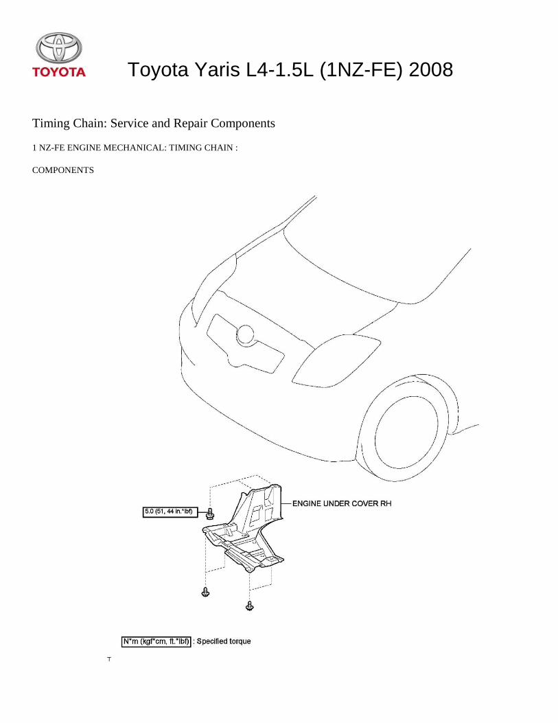
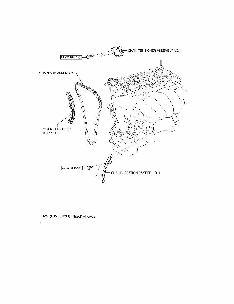
COMPONENTS
Toyota Yaris L4-1.5L (1NZ-FE) 2008


Timing Chain: Service and Repair Removal
1 NZ-FE ENGINE MECHANICAL: TIMING CHAIN :
REMOVAL
1. DISCONNECT CABLE FROM NEGATIVE BATTERY TERMINAL
2. REMOVE FRONT WHEEL RH
3. REMOVE ENGINE UNDER COVER RH
4. DRAIN ENGINE OIL
5. DRAIN ENGINE COOLANT See: Cooling System/Coolant/Service and Repair
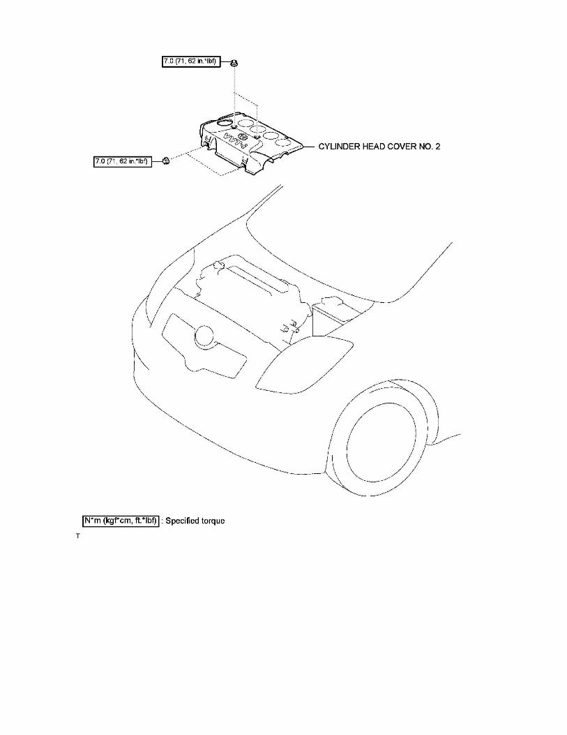
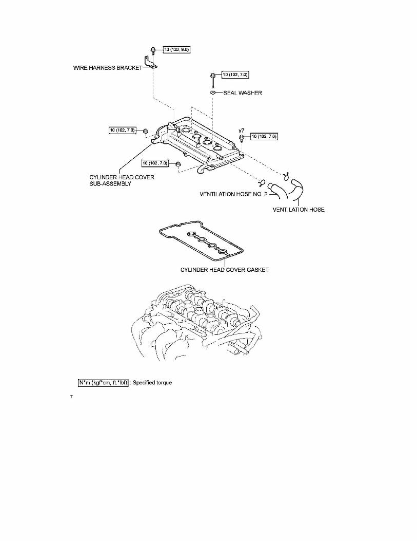
6. REMOVE CYLINDER HEAD COVER NO. 2 See: Powertrain Management/Ignition System/Ignition Coil/Service and
Repair/Removal
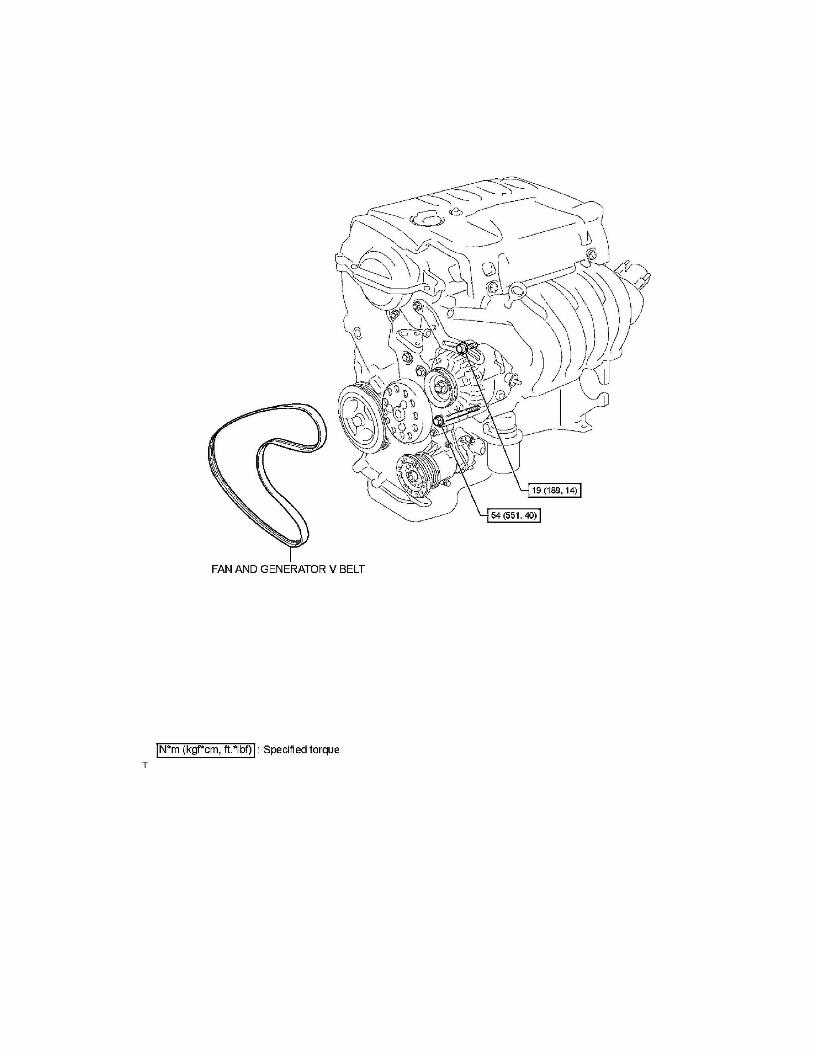
7. REMOVE FAN AND GENERATOR V BELT See: Drive Belts, Mounts, Brackets and Accessories/Drive Belt/Service and
Repair/Removal
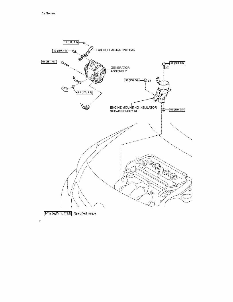
8. REMOVE GENERATOR ASSEMBLY
9. REMOVE IGNITION COIL NO. 1 See: Powertrain Management/Ignition System/Ignition Coil/Service and Repair/Removal
10. DISCONNECT VENTILATION HOSE See: Powertrain Management/Fuel Delivery and Air Induction/Fuel Injector/Service
and Repair/Removal
11. DISCONNECT VENTILATION HOSE NO. 2 See: Powertrain Management/Fuel Delivery and Air Induction/Fuel
Injector/Service and Repair/Removal
12. REMOVE CYLINDER HEAD COVER SUB-ASSEMBLY See: Powertrain Management/Fuel Delivery and Air Induction/Fuel
Injector/Service and Repair/Removal
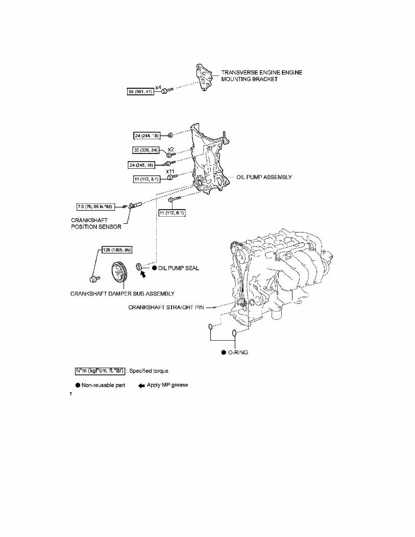
13. REMOVE ENGINE MOUNTING INSULATOR SUB-ASSEMBLY RH See: Engine Lubrication/Oil Pump/Service and
Repair/Removal
14. REMOVE CRANKSHAFT DAMPER SUB-ASSEMBLY See: Engine Lubrication/Oil Pump/Service and Repair/Removal
15. REMOVE CRANKSHAFT POSITION SENSOR See: Powertrain Management/Computers and Control Systems/Crankshaft
Position
Sensor/Service and Repair/Removal
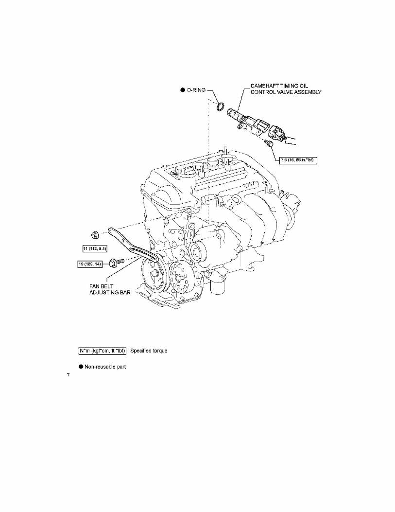
16. REMOVE CAMSHAFT TIMING OIL CONTROL VALVE ASSEMBLY See: Variable Valve Timing/Variable Valve Timing
Actuator/Service and Repair/Removal
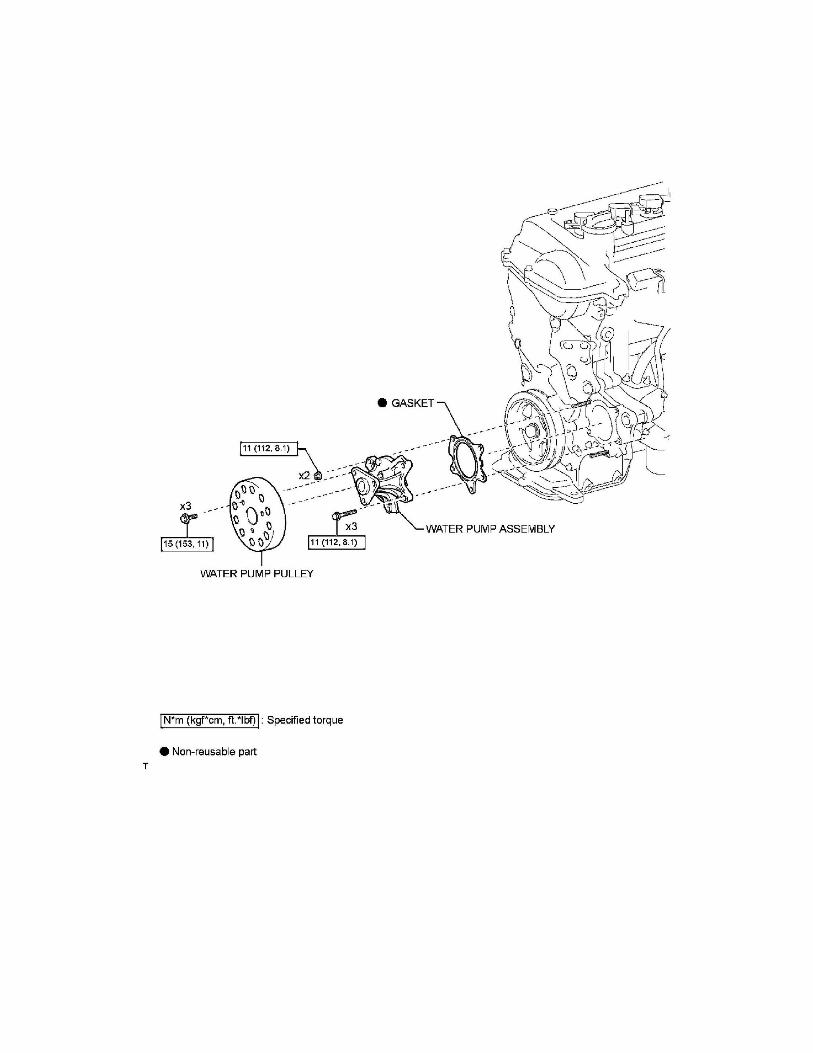
17. REMOVE WATER PUMP PULLEY See: Water Pump/Service and Repair/Removal
18. REMOVE WATER PUMP ASSEMBLY See: Water Pump/Service and Repair/Removal
19. REMOVE TRANSVERSE ENGINE ENGINE MOUNTING BRACKET See: Engine Lubrication/Oil Pump/Service and
Repair/Removal
20. REMOVE OIL PUMP ASSEMBLY See: Engine Lubrication/Oil Pump/Service and Repair/Removal
21. REMOVE OIL PUMP SEAL See: Engine Lubrication/Oil Pump/Service and Repair/Replacement
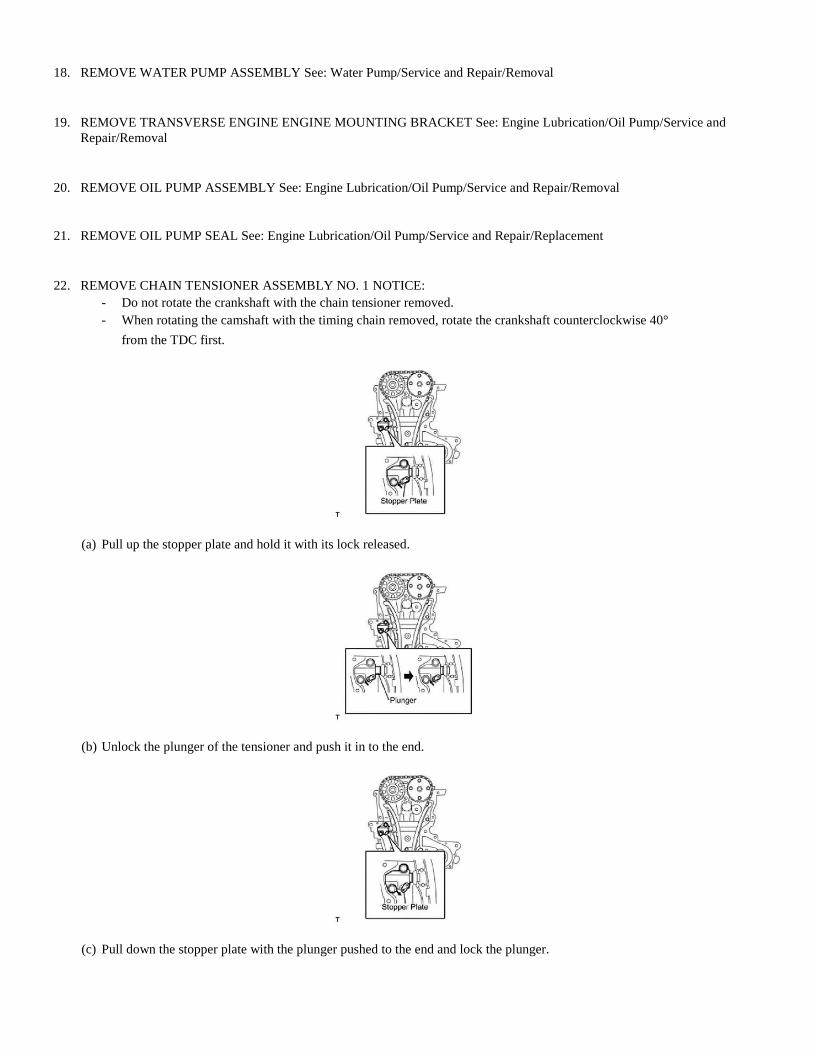
22. REMOVE CHAIN TENSIONER ASSEMBLY NO. 1 NOTICE:
- Do not rotate the crankshaft with the chain tensioner removed.
- When rotating the camshaft with the timing chain removed, rotate the crankshaft counterclockwise 40°
from the TDC first.
(a) Pull up the stopper plate and hold it with its lock released.
(b) Unlock the plunger of the tensioner and push it in to the end.
(c) Pull down the stopper plate with the plunger pushed to the end and lock the plunger.
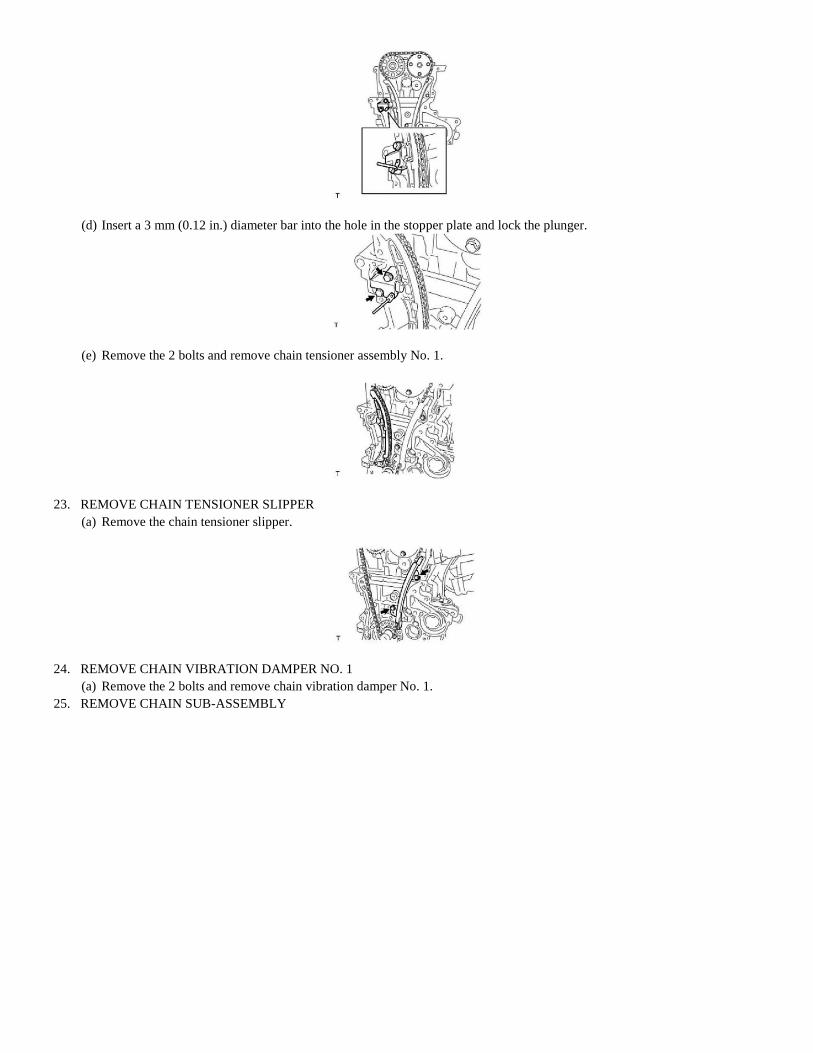
(d) Insert a 3 mm (0.12 in.) diameter bar into the hole in the stopper plate and lock the plunger.
(e) Remove the 2 bolts and remove chain tensioner assembly No. 1.
23. REMOVE CHAIN TENSIONER SLIPPER
(a) Remove the chain tensioner slipper.
24. REMOVE CHAIN VIBRATION DAMPER NO. 1
(a) Remove the 2 bolts and remove chain vibration damper No. 1.
25. REMOVE CHAIN SUB-ASSEMBLY

Timing Chain: Service and Repair Installation
1 NZ-FE ENGINE MECHANICAL: TIMING CHAIN :
INSTALLATION
1. INSTALL CHAIN SUB-ASSEMBLY
(a) Make sure that all the timing marks are in the positions (TDC) shown in the illustration.
HINT: The positions of the timing marks may differ from the predetermined positions due to the force of the valve
spring.
(b) Set the timing mark of the crankshaft in a position between 40 and 140°ATDC as illustrated.

(c) Set the camshaft timing gear and the camshaft timing sprocket in the positions ( 20°ATDC) shown in the illustration. (d) Set
the crankshaft in the position ( 20°ATDC) shown in the illustration.
(e) Install chain vibration damper No. 1 with the 2 bolts.
Torque: 9.0 Nm (92 kgf-cm, 80 in-lbf)
(f) Align the timing marks of the camshaft with the mark plates of the timing chain and install the timing chain.
HINT: Align the timing marks with the mark plates while turning the hexagonal service portion of the camshaft using a
wrench.
2. INSTALL CHAIN TENSIONER SLIPPER
(a) Install the chain tensioner slipper.
3. INSTALL CHAIN TENSIONER ASSEMBLY NO. 1
(a) Install chain tensioner assembly No. 1 with the 2 bolts.
Torque: 9.0 Nm (92 kgf-cm, 80 in-lbf)
(b) Remove the bar from chain tensioner assembly No. 1.
4. INSTALL OIL PUMP SEAL See: Engine Lubrication/Oil Pump/Service and Repair/Replacement
5. INSTALL OIL PUMP ASSEMBLY See: Engine Lubrication/Oil Pump/Service and Repair/Installation
6. INSTALL TRANSVERSE ENGINE ENGINE MOUNTING BRACKET See: Engine Lubrication/Oil Pump/Service and
Repair/Installation
7. INSTALL WATER PUMP ASSEMBLY See: Water Pump/Service and Repair/Installation
8. INSTALL WATER PUMP PULLEY See: Water Pump/Service and Repair/Installation
9. INSTALL CAMSHAFT TIMING OIL CONTROL VALVE ASSEMBLY See: Variable Valve Timing/Variable Valve Timing
Actuator/Service and Repair/Installation
10. INSTALL CRANKSHAFT POSITION SENSOR See: Powertrain Management/Computers and Control Systems/Crankshaft
Position
Sensor/Service and Repair/Installation
11. INSTALL CRANKSHAFT DAMPER SUB-ASSEMBLY See: Engine Lubrication/Oil Pump/Service and Repair/Installation
12. INSTALL ENGINE MOUNTING INSULATOR SUB-ASSEMBLY RH See: Engine Lubrication/Oil Pump/Service and
Repair/Installation
13. INSTALL CYLINDER HEAD COVER SUB-ASSEMBLY See: Powertrain Management/Fuel Delivery and Air Induction/Fuel
Injector/Service and Repair/Installation
14. CONNECT VENTILATION HOSE NO. 2 See: Powertrain Management/Fuel Delivery and Air Induction/Fuel Injector/Service
and
Repair/Installation
15. CONNECT VENTILATION HOSE See: Powertrain Management/Fuel Delivery and Air Induction/Fuel Injector/Service and
Repair/Installation
16. INSTALL IGNITION COIL NO. 1 See: Powertrain Management/Ignition System/Ignition Coil/Service and Repair/Installation
17. INSTALL GENERATOR ASSEMBLY
18. INSTALL FAN AND GENERATOR V BELT See: Drive Belts, Mounts, Brackets and Accessories/Drive Belt/Service and
Repair/Installation
19. ADJUST FAN AND GENERATOR V BELT See: Drive Belts, Mounts, Brackets and Accessories/Drive Belt/Service and
Repair/Installation
20. INSPECT FAN AND GENERATOR V BELT See: Drive Belts, Mounts, Brackets and Accessories/Drive Belt/Service and
Repair/Installation
21. CONNECT CABLE TO NEGATIVE BATTERY TERMINAL
Torque: 5.4 Nm (55 kgf-cm, 48 in-lbf)
22. ADD ENGINE OIL
23. ADD ENGINE COOLANT See: Cooling System/Coolant/Service and Repair
24. CHECK ENGINE OIL LEVEL See: Engine Lubrication/Testing and Inspection
25. CHECK FOR ENGINE OIL LEAKAGE
26. CHECK FOR ENGINE COOLANT LEAKAGE See: Cooling System/Testing and Inspection
27. INSTALL CYLINDER HEAD COVER NO. 2 See: Powertrain Management/Ignition System/Ignition Coil/Service and
Repair/Installation
28. INSTALL ENGINE UNDER COVER RH
29. INSTALL FRONT WHEEL RH
Torque: 103 Nm (1050 kgf-cm, 76 ft-lbf)


