
1468
Technical data
Accessories Ref. no.:
Supply voltage Ref. no.:
CS035003 000831
For more productsin this line...
seenextpage.
Protects and monitors motors with integrated PTCresistor sensorsAutomatic resetSeveral sensors can be connectedControl of bimetalsExcellent cost / performance ratio
Operation
The MSE protects and controls motors fitted withPTC resistor sensors. The temperature sensors areincorporated in the starter windings and measuredirectly the motor heating. Thus, a direct controlis guaranteed under the following operating condi-tions: heavy duty, high switching frequency,single-phasing, high ambient temperature, andinsufficient cooling.The relay is independent of the motor rated currentand the method of starting. The PTC resistorsensors are connected in series with the terminalsT1 and T2. The number of PTC sensor resistorsthat can be connected per measuring circuit islimited by the sum of the PTC sensor resistors ofthe individual resistors.RG = R1 + R2 + RN ≤ 1,5 kΩ. Under normal operatingconditions the resistance value is below theresponse value of the MSE. If only one of the PTCresistors heats up excessively, the output relayde-energizes. After cooling down the output relayenergizes automatically.
Approvals: applied for.
Further applications :Temperature monitoring of equipment fitted withPTC resistor sensors, e.g.:Machine roller bearingsHot-air ventilatorsOilAirHeating installations
24 V AC 2 550 805 93110...130 V AC 2 550 800 93220...240 V AC 2 550 801 93
Input circuitSupply voltage - Power consumption A1-A2 220...240 V AC - approx. 1.5 VASupply voltage tolerance -15 % ... +10 %Supply voltage frequency 50...60 HzDuty time 100 %Measuring circuitMeasuring input T1-T2Total PTC resistance ≤ 1.5 kΩResponse value (relay de-energizes) 2.7...3.7 kΩReset value (relay energizes) 1.7...2.3 kΩVoltage at T1-T2, sensor not connected approx. 20 V DCVoltage at T1-T2, at 4000 W < 7.5 V DCCurrent between T1-T2 at 0 W max. 2 mAMax. cable length off 2 x 250 m we recommend a shielded cableOutput circuit 13/14 Relay, 1 N/O contact, closed circuit principleRated voltage VDE 0100, IEC947-1 250 VMax. switching voltage max. 250 V ACRated operational current AC 12 (ohmic) 4 A (at 230 V)Rated operational current AC 15 (inductive) 3 A (at 230 V)Rated operational current DC 12 (ohmic) 4 A (at 24 V)Rated operational current DC 13 (inductive) 2 A (at 24 V)Mechanical life (max.) 30 x 106 operationsElectrical life (max.) (to AC 12 / 230 V / 4 A) 1 x 10⁵ operationsShort-circuit protection, max. fuse rating 10 A / fast, type gLGeneral dataRated impulse withstand voltage Vimp 4 kVOperating temperature range -20°C ... +60°CStorage temperature range -40°C ... +80°CMounting position anyMounting on DIN-rail (EN 50022) Snap-on mounting/screw mounting using adapterTerminal capacity 2 x 16 AWG (2 x 1.5 mm2)Weight approx. 0.24 lb (110 g)Dimensions (W x H x D) 22.5 x 78 x 78.5 mm
Resistance characteristicfor one temperature sensor acc. toDIN 44 081.
NAT = rated response temperature
ThermistorMotor protection relayMSE mecotron®

1469
Technical data
Accessories Ref. no.:
Supply voltage Ref. no.:
CS035004 000831
For more productsin this line...
seenextpage.
ThermistorMotor protection relayMSS mecotron®
Protects and monitors motors with built-in PTCresistor sensors2 supply voltage versions1 SPDT contact2 LEDsAutomatic restart
Sealable transparent cover 3 430 005 01Adapter for screw mounting 3 430 029 01
Operation
The MSS protects and monitors motors that arefitted with PTC resistor sensors. The temperaturesensors are incorporated in the starter windingsand measure temperature rise. Thus, goodprotection is guaranteed under the followingoperating conditions: heavy duty, high switchingfrequency, single phasing, high operatingtemperature, insufficient cooling.The relay is independent of motor rated current,insulation class, and method of starting.The PTC resistor sensors are connected in serieswith terminals T1 and T2. The number of PTCresistor sensors that can be connected to themeasuring circuit is limited by the sum of PTCresistor sensors of the individual resistor.RG = R1 + R2 + RN ≤ 1.5 kΩ.Under normal operating conditions, theirresistance value is below the response value ofthe MSS. If only one of the PTC resistors heats upexcessively, the output relay is de-energized.It is again energized automatically after the PTCresistor sensor has cooled down in the case ofauto reset.
Input circuitSupply voltage - power consumption A1-A2 24V AC/DC - approx. 1.5 VA/W
A1-A2 220...240 V AC - approx.1.5 VATolerance of supply voltage -15 % ... +10 %Supply voltage frequency 50...60 HzDuty time 100 %Measuring circuitMeasuring input T1-T2Total resistance in cold state ≤ 1.5 kΩResponse value (relay de-energizes) 2.5...3.6 kΩReset value (relay energizes) 1.5...2.3 kΩVoltage at T1-T2, opened max. 35 V DCVoltage at T1-T2, at 4000 Ω ≤ 7.5 V DCMax. cable length, unshielded ≤ 100 mDisplay of operating statusSupply power "U" LED, greenFault tripping "F" LED, redOutput circuit 11-12/14 Relay, 1 SPDT contact, closed-circuit principleRated voltage VDE 0100, IEC947-1 250 VMax. switching voltage max. 250 V ACRated switching current AC 12 (resistive) 4 A (at 230 V)Rated switching current AC 15 (inductive) 3 A (at 230 V)Rated switching current DC 12 (resistive) 4 A (at 24 V)Rated switching current DC 13 (inductive) 2 A (at 24 V)Maximum mechanical life 30 x 106 operationsMaximum electrical life (acc. to AC 12 / 230 V / 4 A) 1 x 10⁵ operationsShort-circuit proof, max. fuse rating 10 A / fast, operation class gLGeneral dataRated impulse withstand voltage Vimp 4 kVOperating temperature -25°C ... +65°CStorage temperature -40°C ... +85°CMounting position anyMounting to DIN rail (EN 50022) Snap-on mounting/Screw-mounting with adapterWire size stranded with wire end ferrule 2 x 14 AWG (2 x 2.5 mm2)Weight approx. 0.33 lb (150 g)Dimensions (W x H x D) 22.5 x 78 x 101 mm
24 V AC/DC 2 430 800 91220...240 V AC 2 430 801 11
Further application possibilities:Temperature monitoring of equipment fitted withPTC resistor sensors, e.g.:Machine roller bearingsHot-air ventilatorsOilAirHeating installations
Resistance characteristicof one temperature sensor to DIN 44 081.
NAT = rated response temperature
Approvals:

1470
Note
Technical data
Accessories Ref. no.:
Supply voltage Ref. no.:
Reset
CS035005 000831
For more productsin this line...
seenextpage.
Operation
The MSS protects and monitors motors that arefitted with PTC resistor sensors. The temperaturesensors are incorporated in the starter windingsand measure temperature rise. Thus, goodprotection is guaranteed under the followingoperating conditions: heavy duty, high switchingfrequency, single phasing, high operatingtemperature, insufficient cooling.The relay is independent of motor rated current,insulation class, and method of starting.The PTC resistor sensors are connected in serieswith terminals T1 and T2 (respectively T1 and T2x,without short-circuit detection). The number of PTCresistor sensors that can be connected to themeasuring circuit is limited by the sum of PTCresistor sensors of the individual resistor.RG = R1 + R2 + RN ≤ 1.5 kΩ.Under normal operating conditions, their resistancevalue is below the response value of the MSS. Ifonly one of the PTC resistors heats up excessively,the output relay is de-energized.
Input circuitSupply voltage - power consumption A1-A2 24V AC/DC - approx. 1.2 VA/ 0.6 W
A1-A2 110...130 V AC - approx. 1.6 VAA1-A2 220...240 V AC - approx. 1.6 VAA1-A2 380...415 V AC - approx. 1.6 VA
Tolerance of supply voltage -15 % ... +10 % (24 V DC: ± 10%)Supply voltage frequency 50...60 HzDuty time 100 %Measuring circuitMeasuring input T1-T2 (T2x)Total resistance in cold state ≤ 1.5 kΩResponse value (relay de-energizes) 3.6 kΩ ± 5 %Short-circuit detection ≤ 20 ΩReset value (relay energizes) 1.6 kΩ ± 5 %Voltage at T1-T2 (T2x), opened max. 6.5 V DCVoltage at T1-T2 (T2x), at 4000 Ω ≤ 3.5 V DCMax. cable length, unshielded ≤ 100 m at 0,75 mm2 (*) 400 m at 2,5 mm2 (*)
(*) when using short-circuit monitoringRemote reset S1-T2 n/o contactMax. cable length between S1 and T2 ≤ 50 mDisplay of operating statusSupply voltage "U" LED, greenFault tripping "F" LED, redOutput circuit 11-12/14,21-22/24 Relay, 2 SPDT contacts, closed-circuit principleRated voltage VDE 0100, IEC947-1 250 VRated switching voltage max. 250 V ACRated switching current AC 12 (resistive) 4 A (at 230 V)Rated switching current AC 15 (inductive) 3 A (at 230 V)Rated switching current DC 12 (resistive) 4 A (at 24 V)Rated switching current DC 13 (inductive) 2 A (at 24 V)Maximum mechanical life 30 x 106 operationsMaximum electrical life (acc. to AC 12 / 230 V / 4 A) 1 x 10⁵ operationsShort-circuit proof, max. fuse rating 10 A / fast, operation class gLGeneral dataRated impulse withstand voltage Vimp 4 kVOperating temperature -25°C ... +65°CStorage temperature -40°C ... +85°CMounting position anyMounting to DIN rail (EN 50022) Snap-on mounting/ Screw mounting with adapterWire size stranded with wire end ferrule 2 x 14 AWG (2 x 2.5 mm2)Weight approx. 0.33 lb (150 g)
Configurable short-circuit monitoring of the sensorcircuit4 supply voltage versionsStorage resettableStorage reset buttonRemote reset capabilityShort-circuit monitoring of the sensor cable2 SPDT contacts2 LEDs
24 V AC/DC 2 430 710 93110...130 V AC 2 430 711 03220...240 V AC 2 430 711 13380...415 V AC 2 430 711 23
24 V AC/DC version without electrical isolation and withoutPTB approval.
It is again energized automatically after the PTCresistor sensor has cooled down in the case ofauto reset.Auto reset is achieved by a permanent link (jumper)of the terminals S1 and T2. In the case of manualreset, the reset button must be pressed.Remote resetting is achieved by a short-timelinking of the terminals S1 and T2.
Sealable transparent cover 3 430 005 01Adapter for screw mounting 3 430 029 01
Further application possibilities:Temperature monitoring of equipment fitted withPTC resistor sensors, e.g.:Machine roller bearingsHot-air ventilatorsOilAirHeating installations
Resistance characteristicof one temperature sensor to DIN 44 081.
NAT = rated response temperature
ThermistorMotor protection relayMSS mecotron®
24 V AC/DC version without electrical isolation and withoutPTB approval.
Approvals:
jumper S1-T2= without storage
Measuring circuit
T1 - T2x
= without short-circuit monitoring
Remotereset
Note:Dimensions (W x H x D), 22.5 x 78 x 101 mm

1471
Technical data
Accessories Ref. no.:
Supply voltage Ref. no.:
Reset
CS035007 000831
For more productsin this line...
seenextpage.
Operation
The MSS protects and monitors motors that arefitted with PTC resistor sensors. The temperaturesensors are incorporated in the starter windingsand measure temperature rise. Thus, goodprotection is guaranteed under the followingoperating conditions: heavy duty, high switchingfrequency, single phasing, high operatingtemperature, insufficient cooling.The relay is independent of motor rated current,insulation class, and method of starting.The PTC resistor sensors are connected in serieswith terminals T1 and T2 (respectively 2T1 andT2). The number of PTC resistor sensors that canbe connected to the measuring circuit is limitedby the sum of PTC resistor sensors of the individualresistor.RG = R1 + R2 + RN ≤ 1.5 kΩ.Under normal operating conditions, their resistancevalue is below the response value of the MSS. Ifonly one of the PTC resistors heats up excessively,the output relay is de-energized. It is againenergized automatically after the PTC resistorsensor has cooled down in the case of auto reset.
Input circuitSupply voltage - power consumption A1-A2 24...240 V AC/DC - approx. 1.1 VA / W (24 V)
approx. 5.7 VA/ W (240 V)Tolerance of supply voltage -15 % ... +10 %Frequency of AC supply 15...400 HzDuty time 100 %Measuring circuitMeasuring input 1T1-T2, 2T1-T2Total resistance in cold state ≤ 1.5 kΩ per sensor circuitResponse value (relay de-energizes) 3.6 kΩ ± 5%Short-circuit detection ≤ 20 ΩReset value (relay energizes) 1.6 kΩ ± 5%Voltage at xT1-T2 , opened max. 6.5 V DCVoltage at xT1-T2 , at 4000 Ω ≤ 3.5 V DCMax. cable length, unshielded ≤ 100 m at 0.75 mm2 400 m at 2.5 mm2
Remote reset S1-T2 n/o contactMax. cable length between S1 and T2 ≤ 50 mDisplay of operating statusSupply voltage "U" LED, greenFault tripping sensor circuit 1 "F1" / sensor circuit 2 "F2" LED, red / LED, redOutput circuit 13-14 / 21-22 2 Relays, each one SPDT contact, closed-circuit principleRated voltage VDE 0100, IEC947-1 250 VRated switching voltage max. 250 V ACRated switching current AC 12 (resistive) 4 A (at 230 V)Rated switching current AC 15 (inductive) 3 A (at 230 V)Rated switching current DC 12 (resistive) 4 A (at 24 V)Rated switching current DC 13 (inductive) 2 A (at 24 V)Maximum mechanical life 30 x 106 operationsMaximum electrical life (acc. to AC 12 / 230 V / 4 A) 1 x 10⁵ operationsShort-circuit proof, max. fuse rating 10 A / fast, operation class gLGeneral dataRated impulse withstand voltage Vimp 4 kVOperating temperature -25°C ... +65°CStorage temperature -40°C ... +85°CMounting position anyMounting to DIN rail (EN 50022) Snap-on mounting/ Screw mounting with adapterWire size stranded with wire end ferrule 2 x 14 AWG (2 x 2.5 mm2)Weight approx. 0.33 lb (150 g)Dimensions (W x H x D) 22.5 x 78 x 101 mm
2 separate sensor circuits to monitor two motors, or tomonitor one motor with 2 sensor circuits (prewarningand final switch off)Short-circuit monitoring of the sensor circuitContinuous supply voltage range 24...240 V AC/DCStorage resettableStorage reset buttonRemote reset capability2 SPDT contacts; one each per sensor circuit3 LEDs
24 V...240 AC/DC 2 430 710 02
Auto reset is achieved by a permanent link (jumper)of the terminals S1 and T2. In the case of manualreset, the reset button must be pressed.Remote resetting is achieved by a short-timelinking of the terminals S1 and T2.
Sealable transparent cover 3 430 005 01Adapter for screw mounting 3 430 029 01
Further application possibilities:Temperature monitoring of equipment fitted withPTC resistor sensors, e.g.:Machine roller bearingsHot-air ventilatorsOilAirHeating installations
Resistance characteristicof one temperature sensor to DIN 44 081.
NAT = rated response temperature
ThermistorMotor protection relayMSS mecotron®
Approvals:
with 2 independent sensor circuitsand single evaluation
jumper S1-T2
= without storage
Remotereset

1472
Technical data
Accessories Ref. no.:
Supply voltage Ref. no.:
Reset/Test
24 ...240 AC/DC 2 430 720 04
CS035006 000831
For more productsin this line...
seenextpage.
Operation
The MSS protects and monitors motors that arefitted with PTC resistor sensors. The temperaturesensors are incorporated in the starter windingsand measure temperature rise. Thus, goodprotection is guaranteed under the followingoperating conditions: heavy duty, high switchingfrequency, single phasing, high operatingtemperature, insufficient cooling.The relay is independent of motor rated current,insulation class, and method of starting.The PTC resistor sensors are connected in serieswith terminals T1 and T2 (respectively T1 and T2x,without short-circuit detection). The number of PTCresistor sensors that can be connected to themeasuring circuit is limited by the sum of PTCresistor sensors of the individual resistor.RG = R1 + R2 + RN ≤ 1.5 kΩ.Under normal operating conditions, their resistancevalue is below the response value of the MSS. Ifonly one of the PTC resistors heats up excessively,the output relay is de-energized. It is againenergized automatically after the PTC resistorsensor has cooled down in the case of auto reset.Auto reset is achieved by a permanent link (jumper)
Input circuitSupply voltage - power consumption A1-A2 24...240 V AC/DC - approx. 1.5 VA / W (24 V)
approx. 1.5 W (240 V DC)approx. 3.3 VA (240 V AC/ 60 Hz)
Tolerance of supply voltage -15 % ... +10 %Frequency of AC supply 15...400 HzDuty time 100 %Measuring circuitMeasuring input T1-T2Total resistance in cold state ≤ 1.5 kΩResponse value (relay de-energizes) 3.6 kΩ ± 5%Short-circuit detection ≤ 20 ΩReset value (relay energizes) 1.6 kW ± 5%Voltage at xT1-T2 , opened max. 6.5 V DCVoltage at xT1-T2 , at 4000 Ω ≤ 3.5 V DCMax. cable length, unshielded ≤ 100 m at 0.75 mm2 400 m at 2.5 mm2
Remote reset S1-T2 n/o contactMax. cable length between S1 and T2 ≤ 50 mDisplay of operating statusSupply voltage "U" LED, greenFault tripping "F" LED, redOutput circuit 13-14,21-22 2 Relays, 1 n/o + 1 n/c, closed-circuit principleRated voltage VDE 0100, IEC947-1 250 VMax. switching voltage max. 250 V ACRated switching current AC 12 (resistive) 4 A (at 230 V)Rated switching current AC 15 (inductive) 3 A (at 230 V)Rated switching current DC 12 (resistive) 4 A (at 24 V)Rated switching current DC 13 (inductive) 2 A (at 24 V)Maximum mechanical life 30 x 106 operationsMaximum electrical life (acc. to AC 12 / 230 V / 4 A) 1 x 10⁵ operationsShort-circuit proof, max. fuse rating 10 A / fast, operation class gLGeneral dataRated impulse withstand voltage Vimp 4 kVOperating temperature -25°C ... +65°CStorage temperature -40°C ... +85°CMounting position anyMounting to DIN rail (EN 50022) Snap-on mounting/ Screw mounting with adapterWire size stranded with wire end ferrule 2 x 14 AWG (2 x 2.5 mm2)Weight approx. 0.33 lb (150 g)Dimensions (W x H x D) 22.5 x 78 x 101 mm
Configurable Non-volatile storage (Retentivity)in case of failureShort-circuit monitoring of the sensor circuitContinuous supply voltage range 24...240 V AC/DCStorage resettableStorage reset buttonRemote reset capabilityShort-circuit monitoring of the sensor cable2 output contacts: 1 n/o and 1 n/c contact2 LEDs
of the terminals S1 and T2. In the case of manualreset, the reset button must be pressed.Remote resetting is achieved by a short-timelinking of the terminals S1 and T2.
Sealable transparent cover 3 430 005 01Adapter for screw mounting 3 430 029 01
Further application possibilities:Temperature monitoring of equipment fitted withPTC resistor sensors, e.g.:Machine roller bearingsHot-air ventilatorsOilAirHeating installations
Resistance characteristicof one temperature sensor to DIN 44 081.
NAT = rated response temperature
ThermistorMotor protection relayMSS mecotron®
Approvals:
with configurable non-volatilestorage in case of failure
jumper S1-T2
= without storage
Remotereset

1473
Technical data
Accessories Ref. no.:
Supply voltage Ref. no.:
24 ...240 AC/DC 2 430 720 05
Reset/Test
CS035008 000831
For more productsin this line...
seenextpage.
Operation
The MSS protects and monitors motors that arefitted with PTC resistor sensors. The temperaturesensors are incorporated in the starter windingsand measure temperature rise. Thus, goodprotection is guaranteed under the followingoperating conditions: heavy duty, high switchingfrequency, single phasing, high operatingtemperature, insufficient cooling.The relay is independent of motor rated current,insulation class, and method of starting.The PTC resistor sensors are connected in serieswith terminals T1 and T2 (respectively T1 and T2x,without short-circuit detection). The number of PTCresistor sensors that can be connected to themeasuring circuit is limited by the sum of PTCresistor sensors of the individual resistor.RG = R1 + R2 + RN ≤ 1.5 kΩ.Under normal operating conditions, their resistancevalue is below the response value of the MSS. Ifonly one of the PTC resistors heats up excessively,the output relay is de-energized. It is againenergized automatically after the PTC resistorsensor has cooled down in the case of auto reset.
Input circuitSupply voltage - power consumption A1-A2 24...240 V AC/DC - approx. 1.5 VA / W (24 V)
approx. 1.5 W (240 V DC)approx. 3.3 VA (240 V AC/ 60 Hz)
Tolerance of supply voltage -15 % ... +10 %Frequency of AC supply 15...400 HzDuty time 100 %Measuring circuitMeasuring inputs 1T1, 2T1,3T1-T2 3 sensor circuitsTotal resistance in cold state ≤ 1.5 kΩResponse value (relay de-energizes) 3.6 kΩ ± 5%Short-circuit detection ≤ 20 ΩReset value (relay energizes) 1.6 kΩ ± 5%Voltage at xT1-T2 , opened max. 6.5 V DCVoltage at xT1-T2 , at 4000 Ω ≤ 3.5 V DCMax. cable length, unshielded ≤ 100 m at 0.75 mm2 400 m at 2.5 mm2
Remote reset S1-T2 n/o contactMax. cable length between S1 and T2 ≤ 50 mDisplay of operating statusSupply voltage "U" LED, greenFault tripping sensor circuits 1"F1" / 2"F2" / 3"F3" each one LED, redOutput circuit 13-14 / 21-22 2 Relays, 1 n/o + 1 n/c, closed-circuit principleRated voltage VDE 0100, IEC947-1 250 VRated switching voltage max. 250 V ACRated switching current AC 12 (resistive) 4 A (at 230 V)Rated switching current AC 15 (inductive) 3 A (at 230 V)Rated switching current DC 12 (resistive) 4 A (at 24 V)Rated switching current DC 13 (inductive) 2 A (at 24 V)Maximum mechanical life 30 x 106 operationsMaximum electrical life (acc. to AC 12 / 230 V / 4 A) 1 x 10⁵ operationsShort-circuit proof, max. fuse rating 10 A / fast, operation class gLGeneral dataRated impulse withstand voltage Vimp 4 kVOperating temperature -25°C ... +65°CStorage temperature -40°C ... +85°CMounting position anyMounting to DIN rail (EN 50022) Snap-on mounting/ Screw mounting with adapterWire size stranded with wire end ferrule 2 x 14 AWG (2 x 2.5 mm2)Weight approx. 0.33 lb (150 g)Dimensions (W x H x D) 22.5 x 78 x 101 mm
Total evaluation of up to 3 sensor circuitsShort-circuit monitoring of the sensor circuitContinuous supply voltage range 24...240 V AC/DCConfigurable non-volatile storageStorage resettableRemote reset capability2 output contacts: 1 n/o and 1 n/c contactAutoreset4 LEDs
Auto reset is achieved by a permanent link (jumper)of the terminals S1 and T2. In the case of manualreset, the reset button must be pressed.Remote resetting is achieved by a short-timelinking of the terminals S1 and T2.
Sealable transparent cover 3 430 005 01Adapter for screw mounting 3 430 029 01
Further application possibilities:Temperature monitoring of equipment fitted withPTC resistor sensors, e.g.:Machine roller bearingsHot-air ventilatorsOilAirHeating installations
Resistance characteristicof one temperature sensor to DIN 44 081.
NAT = rated response temperature
ThermistorMotor protection relayMSS mecotron®
Approvals:
with 3 sensor circuits and totalevaluation, with configurable non-volatile storage in case of failure
jumper S1-T2
= without storage
Remotereset

1474
Technical data
Accessories Ref. no.:
Supply voltage Ref. no.:
Reset/Test
24 V...240 AC/DC 2 450 025 01
CS035009 000831
Operation
The MSN protects and monitors motors that arefitted with PTC resistor sensors. The temperaturesensors are incorporated in the starter windingsand measure temperature rise. Thus, goodprotection is guaranteed under the followingoperating conditions: heavy duty, high switchingfrequency, single phasing, high operatingtemperature, insufficient cooling.The relay is independent of motor rated current,insulation class, and method of starting.The PTC resistor sensors are connected in serieswith terminals T1 and T2 (respectively T1 and T2x,without short-circuit detection). The number of PTCresistor sensors that can be connected to themeasuring circuit is limited by the sum of PTCresistor sensors of the individual resistor.RG = R1 + R2 + RN ≤ 1.5 kΩ.Under normal operating conditions, their resistancevalue is below the response value of the MSN. Ifonly one of the PTC resistors heats up excessively,the output relay is de-energized. It is againenergized automatically after the PTC resistorsensor has cooled down in the case of auto reset.Auto reset is achieved by a permanent link (jumper)
Input circuitSupply voltage - power consumption A1-A2 24...240 V AC/DC - approx. 1.5 VA / W (24 V)
approx. 1.5 W (240 V DC)approx. 3.3 VA (240 V AC/ 60 Hz)
Tolerance of supply voltage -15 % ... +10 %Frequency of AC supply 15...400 HzDuty time 100 %Measuring circuitMeasuring inputs 1T1, 2T1,... 6T1-T2 6 sensor circuitsTotal resistance in cold state ≤ 1.5 kΩ per sensor circuitResponse value (relay de-energizes) 3.6 kΩ ± 5%Reset value (relay energizes) 1.6 kΩ ± 5%Voltage at xT1-T2 , opened max. 6.5 V DCVoltage at xT1-T2 , at 4000 Ω ≤ 3.5 V DCMax. cable length, unshielded ≤ 100 m at 0.75 mm2 400 m at 2.5 mm2
Remote reset S1-T2 n/o contactMax. cable length between S1 and T2 ≤ 50 mDisplay of operating statusSupply voltage "U" LED, greenFault tripping sensor circuit 1...6 "F1"..."F6" LED, redOutput circuit 13-14 / 21-22 2 Relays, 1 n/o + 1 n/c, closed-circuit principleRated voltage VDE 0100, IEC947-1 250 VRated switching voltage max. 250 V ACRated switching current AC 12 (resistive) 4 A (at 230 V)Rated switching current AC 15 (inductive) 3 A (at 230 V)Rated switching current DC 12 (resistive) 4 A (at 24 V)Rated switching current DC 13 (inductive) 2 A (at 24 V)Maximum mechanical life 30 x 106 operationsMaximum electrical life (acc. to AC 12 / 230 V / 4 A) 1 x 10⁵ operationsShort-circuit proof, max. fuse rating 10 A / fast, operation class gLGeneral dataRated impulse withstand voltage Vimp 4 kVOperating temperature -25°C ... +65°CStorage temperature -40°C ... +85°CMounting position anyMounting to DIN rail (EN 50022) Snap-on mounting/ Screw mounting with adapterWire size stranded with wire end ferrule 2 x 14 AWG (2 x 2.5 mm2)Weight approx. 0.51 lb (230 g)Dimensions (W x H x D) 45 x 78 x 101 mm
Total evaluation of up to 6 sensor circuitsShort-circuit monitoring of the sensor circuitContinuous supply voltage range 24...240 V AC/DCConfigurable non-volatile storage2 Storages resettableRemote reset capabilityAutoresetStorage reset and test button2 output contacts: 1 n/o and 1 n/c contact7 LEDs
of the terminals S1 and T2. In the case of manualreset, the reset button must be pressed.Remote resetting is achieved by a short-timelinking of the terminals S1 and T2.
Sealable transparent cover 3 430 005 01Adapter for screw mounting 3 430 029 01
Further application possibilities:Temperature monitoring of equipment fitted withPTC resistor sensors, e.g.:Machine roller bearingsHot-air ventilatorsOilAirHeating installations
Resistance characteristicof one temperature sensor to DIN 44 081.
NAT = rated response temperature
ThermistorMotor protection relayMSN mecotron®
Approvals:
with 6 sensor circuits and totalevaluation, with configurablenon-volatile storage
jumper S1-T2
= without storage
Remotereset

1475
NA8FC2T
Accessories,standards, technical data
001222
3.9(99)
2.9(73)
MP001A01 9.8.00
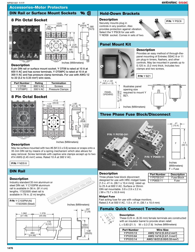
P/N: Y PSC8
Part Number DescriptionY P0700 241 Fuse BlockY P0600 11 Fuse
P/N: Y P0600-11
P/N: Y P0700-241
Female Quick Connect Terminals
1476
Accessories–Motor Protectors
DIN Rail or Surface Mount Sockets
8 Pin Octal Socket
DescriptionMay be surface mounted with two #6 (M 3.5 x 0.6) screws or snaps onto a35 mm DIN rail by means of a spring mechanism which also allows foreasy removal. Screw terminals with captive wire clamps accept up to two#14 AWG (2.45 mm2) wires. Rated 10 A at 300 V AC.
P/N: Y NDS 8
8 Pin Octal Socket
Part Number Rating TerminationY OT08 600 V AC Screws
Y OT08PC 300 V AC Pressure Clamps
DescriptionSecurely mounts plug incontrols in any position. Alsoprovides protection against vibration.Select the Y PSC8 for use withY NDS8 socket. Comes in sets of two.
Description8 pin DIN rail or surface mount socket. Y OT08 is rated at 10 A at600 V AC and has screw terminals. Y OT08PC is rated at 10 A at300 V AC and has pressure clamp terminals. For use with AWG 12to 22 (3.2 to 0.33 mm2) wire sizes.
Inches (Millimeters)
Inches (Millimeters)
Hold-Down Brackets
DescriptionIndustry standard 35 mm aluminum orsteel DIN rail. Y C103PM aluminumrail is available in 36 in. (91.4 cm)lengths. 17322005 steel rail isavailable in 78 in. (2 m) lengths.
P/N: Y C103PM (Al) Y 17322005 (Steel)
DIN Rail
Inches (Millimeters)
Panel Mount KitDescriptionProvides an easy method of through-the-panel mounting of Entrelec SSAC 8 or 11pin plug-in timers, flashers, and othercontrols. May be mounted in panels up to0.125 in. (3.2 mm) thick. Includes twoclamps and two screws.
P/N: Y BZ1
Inches (Millimeters)
Illustrates panelopening sizerequired to mount YBZ1.
DescriptionThree phase fuse block disconnectdesigned for use with HRC midget fuses[1.5 x .41 in. (38.1 x 10.4 mm)] rated upto 25 A at 600 V AC. Surface or 35mmDIN rail mountable. 3.9 x 2.9 x 2.2 in.( 99 x 73.7 x 55.9 mm)
Inches(Millimeters)F = Fuse
Three Phase Fuse Block/Disconnect
DescriptionThese 0.25 in. (6.35 mm) female terminals are constructedwith an insulator barrel to provide strain relief.
LW
Part Number Wire SizeY P1015 13 AWG 10/12 (5.3/3.2 mm2)Y P1015 64 AWG 14/16 (2.5/1.3 mm2)Y P1015 14 AWG 18/22 (0.93/0.33 mm2)
L = 0.83 (21.1) W = 0.3 (7.6) Inches (Millimeters)
Midget FuseFast acting fuse for use with voltage monitors.Rated 2 A at 500 V AC. 1.5 x .41 in. (38.1 x 10.4 mm)

1477
0816T 001120
Accessories
Mechanical Outline and Accessories for mecotron® Monitoring Relays
Marker label P/N: 4 366 017 01
Sealable covers
P/N: 3 430 005 01
Sealable cover for mecotronseries 22.5 mm wide
P/N: 3 440 005 01
Sealable cover for mecotronseries 45 mm wide
Adapter for screw mounting
In 22.5 mm width P/N: 3 430 029 01In 45 mm width P/N: 3 440 029 01
ESS22.5 mm
On the S Series, terminals with cable guides greatlysimplify installation. This also applies to wire endferrules with insulating collars.
S and N Series:Screw Connection
ESN45 mm
PFE22.5 mm
E Series:Screw Connection

1478
0818T 001115
Entrelec SSAC products have been designed, developed, and tested inaccordance with all relevant norms and standards.
Product standards: EN50082-2, EN61010-1Electromagnetic compatibility: 89/336/EECLow-voltage directive: 93/68/EECLow-voltagedirective tests: EN61010-1
CE Conditions of AcceptabilityCE Conditions of AcceptabilityCE Conditions of AcceptabilityCE Conditions of AcceptabilityCE Conditions of Acceptability
Products Containing DIP Switches:Power must be removed from the unit when a switch position is changed.
Products with Solid-State Outputs:Loads rated above 1 A, must be evaluated for CE use when used withsolid-state output products.
UL and CSA ApprUL and CSA ApprUL and CSA ApprUL and CSA ApprUL and CSA Approoooovvvvvalsalsalsalsals
When UL/CSA approvals are indicated, Entrelec SSAC products areUL Recognized* (UL Listed** for DLM and WVM Series) and CSACertified under the file numbers listed below. These products aretested to the requirements of UL508 - Industrial Control Equipment.CSA Certified products are tested to the requirements ofC22.2 Number 14 - Industrial Control Equipment.
Agency Standard Number File NumberUnderwriters Laboratories (UL) UL 508 E57310Canadian Standards Association (CSA) C22.2 Number 14 LR57415
*UL’s Component Recognition Service covers the testing and evaluationof component products that are incomplete or restricted in performancecapabilities. These components will later be used in completeend-products or systems Listed by UL.
**The UL Listed Mark on a product indicates that samples of thatcomplete product have been tested by UL to nationally recognizedSafety Standards and found to be free from reasonably forseeablerisk of fire, electric shock, and related hazards.
The mecotron® range has been designed and developed taking intoconsideration all relevant standards for measuring and monitoring relays.
Product standard: IEC 255 part 6Electromagnetic compat.: 93 / 68 / EWGLow-voltage directive: 93 / 68 / EWG
Mechanical shockresistance: IEC 68 part 2-6: 10 GEnvironmental tests: IEC 68 part 2-30: 24 h cycle, 55°C, 93% rel, 96 hIsolation tests:Overvoltage category: III to VDE 0110, IEC 664; C to IEC 255-5Pollution category: III to VDE 0110, IEC 664; C to IEC 255-5
Test voltage: 2.5 kV / 50 Hz / 1 min. between all isolated circuits
EMC tests: EN 50082-2ESD: IEC 1000-4-2, EN 61000-4-2 level 3 (6 kV / 8 kV)HF radiation resistance: IEC 1000-4-3, EN 61000-4-3 level 3 (3 V / m)Burst: IEC 1000-4-4, EN 61000-4-4 level 3 (2 kV 5 k Hz)Surge: IEC 1000-4-5, EN 61000-4-5 level 4 (2 kV L-L)HF line emission: IEC 1000-4-6, EN 61000-4-6 level 3 (10 V)
Rated impulse withstand voltage VDE 0110, IEC 664 between all isolatedcircuits: 4 kV / 1.2 - 50 µs
Standards and approvals for measuring and monitoring relaysStandards and approvals for measuring and monitoring relays
mecotron® measuring and monitoring relaysSpecial standards and tests
mecotron® PFN, PVN, ASN, EFN, LWN, PFS, PFE, PBE, PVE and ASS
Rated insulation voltage to VDE 0110, IEC 947-1 between supply andMeasuring and output circuit: 500 V
mecotron® ESN and SRN
Rated insulation voltage to VDE 0110, IEC 947-1 between all isolatedcircuits: 400 V
mecotron® ESS, SRS, MSS, MSE, and MSN
Rated insulation voltage VDE 0110, IEC 947-1 between supply andMeasuring and output circuit: 250 V
mecotron® IWN AC
Product norm: IEC 255 part 6 to VDE 0413 part 2Rated insulation voltage VDE 0110, IEC 947-1 between supply andMeasuring and output circuit: 400 V
mecotron® IWN DC
Rated insulation voltage VDE 0110, IEC 947-1 between measuring andsupply circuit: 320 Vbetween output circuit and other circuits: 400 V
Entrelec SSAC measuring and monitoring relays

1479
E021007 000831
Load limit curvesLoad limit curves
Contact life/ no. of operationsReduction factor at inductive AC load
Reduction factor Fat inductive load
Contact life/no. of operations N220 V 50 Hz I AC360 operations/h
DC load (resistive)AC load (resistive)
Contact life/ no. of operationsReduction factor at inductive AC load
Reduction factor Fat inductive load
Contact life/no. of operations N220 V 50 Hz I AC360 operations/h
DC load (resistive)AC load (resistive)
Load limit curves for the mecotron®-N series (45 mm)
Load limit curves for the mecotron®-S series (22.5 mm) and the mecotron®-E series (22.5 mm)

1480
NOTES

1481
Current sensors
NA8FC1T 001222

1482
001016
Sensing/Control Relays
0801T
AC/DC version w/selectableover or undercurrent;relay output.
AC/DC current trip pointsas low as 3mA; adjustablehysteresis; relay output.
Adjustable, AC over &undercurrent trip points w/selectable response modes.
Selectable AC over orundercurrent; adjustabletrip point & delay.
Low cost AC current switch;direct connection to digital PLCinput; sinking or sourcing.
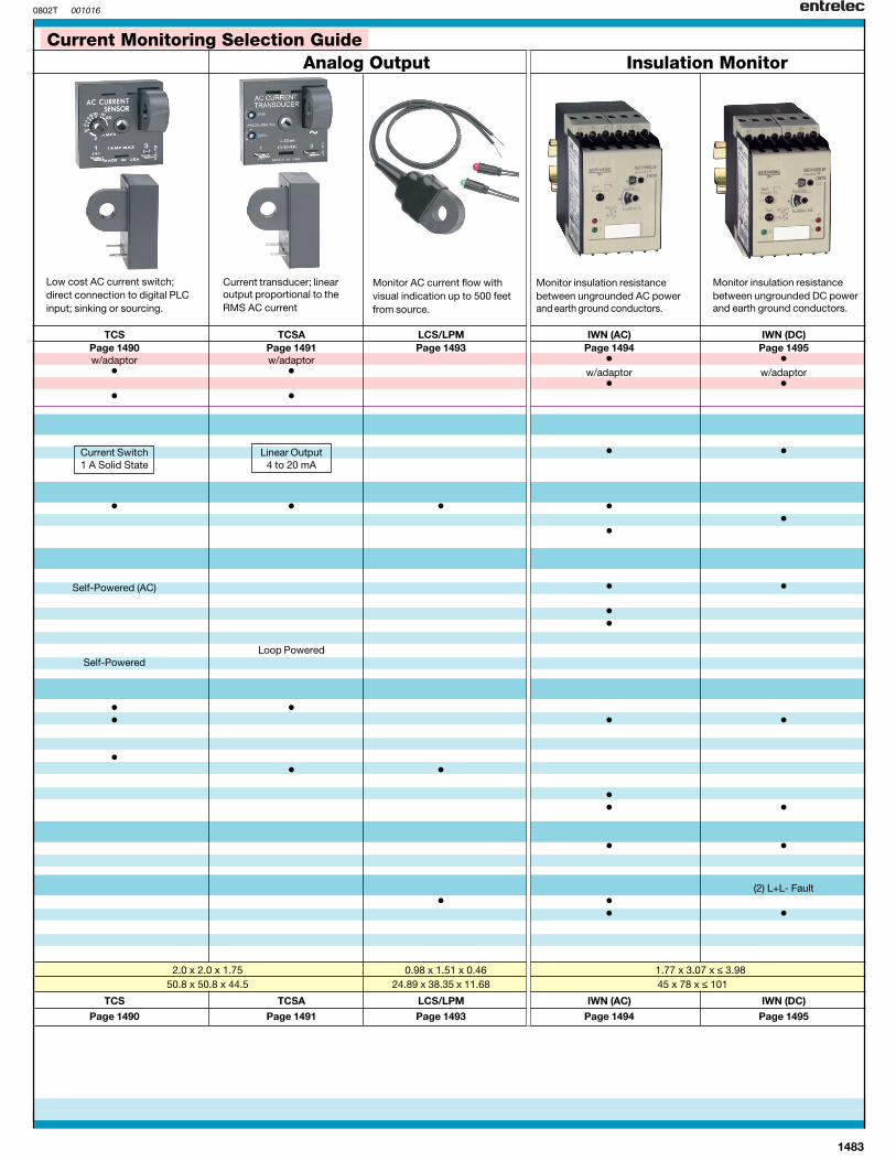
Current MonitoringSelection Guide
Directions:
1.) Select the style of productpackaging you require.
2.) For general features,control, and specificratings, reference thetable below.
3.) Find the product nameand catalog page numberin each column.
For complete productspecifications, referencethe catalog pages.
General Features: SRN SRS ECSW ECSPage 1484 Page 1486 Pages 1488-1489 Page 1487
DIN Rail Mounting • •Surface Mounting w/adaptor w/adaptor • •Screw Terminals • • •Quick Connects •
Output:DPDT Relay •SPDT Relay • • •SPST Solid State
Monitored Current:AC • • • •DC • •Three Phase
Supply Voltage:24 VAC • • •24 … 240 V AC/DC •42 … 48 V AC •110 … 130 V AC • • • •220 … 240 V AC • • • •380 … 415 V AC •12 & 24 V DC • •3 … 50 V DC
Trip Range(s):FixedAdjustable • • • •3 mA … 1 A • •0.3 … 15 A • •2 … 45 A fixed / 2… 20 adjustable0 … 50 A0.5 … 50 A • •1 … 11 K Ω10 … 110 K Ω
Delay(s):Trip • • •Inrush • •
Indicator LED(s):Output ON/OFF • • •Supply ON/OFF • •Fault(s) • •Timing •
Dimensions: in 1.77 x 3.07 x ≤ 3.98 0.886 x 3.07 x ≤ 3.98 2.50 x 3.50 x 1.75(W x H x D) mm 45 x 78 x ≤ 101 22.5 x 78 x ≤ 101 63.5 x 88.9 x 44.5
SRN SRS ECSW ECS
Page 1484 Page 1486 Pages 1488-1489 Page 1487
1483
001016
Analog Output Insulation Monitor
TCS TCSA LCS/LPM IWN (AC) IWN (DC)Page 1490 Page 1491 Page 1493 Page 1494 Page 1495w/adaptor w/adaptor • •
• • w/adaptor w/adaptor• •
• •
Current Switch Linear Output • •1 A Solid State 4 to 20 mA
Monitored Current:• • • •
••
Supply Voltage:
Self-Powered (AC) • •
••
Loop PoweredSelf-Powered
• •• • •
•• •
•• •
• •
I (2) L+L- Fault• •
• •
D 2.0 x 2.0 x 1.75 0.98 x 1.51 x 0.46 1.77 x 3.07 x ≤ 3.98 50.8 x 50.8 x 44.5 24.89 x 38.35 x 11.68 45 x 78 x ≤ 101
TCS TCSA LCS/LPM IWN (AC) IWN (DC)
Page 1490 Page 1491 Page 1493 Page 1494 Page 1495
0802T
Current transducer; linearoutput proportional to theRMS AC current
Monitor AC current flow withvisual indication up to 500 feetfrom source.
Monitor insulation resistancebetween ungrounded AC powerand earth ground conductors.
Monitor insulation resistancebetween ungrounded DC powerand earth ground conductors.
Low cost AC current switch;direct connection to digital PLCinput; sinking or sourcing.
Current Monitoring Selection Guide


