The Internet of Simulation: Enabling Agile Model Based Systems Engineering for Cyber-Physical SystemsStephen Clement, David McKee, Richard Romano, Jie Xu University of Leeds
Jose-Maria Lopez-Rodriguez Simware Solutions
David Battersby Jaguar Land Rover
1

BackgroundLarge-scale complex cyber-physical systems
• IoT: 20+ billion devices by 2020 generating 300 ExaBytes of data• Vehicles: ~100 ECU’s mixing safety critical and non-critical systems
Virtual Engineering• Simulation• Rapid (virtual prototyping)• Explore system behaviours• Life-Cycle – Digital Twins
Raghu Ramakrishnan, CTO for Data
“…if we can concentrate and build platforms that will lift the level of abstraction …you could instead focus on understanding
whatever your domain is, …[if] the tools for making sense of your data …were that much more accessible …the total cost of
ownership would plunge…that's [a] form of [Cloud] amortization. …the tools need to come closer and closer to how you think
about your world...”
Improve virtual engineering life-cycle by providing methods for increased co-simulation and integration
2

MotivationDesign & development of a complex system
• Involving experts and teams in different disciplines (e.g. SE and Computing)• Requiring collaboration between teams• Understanding of the global behaviour of the system• Market pressures, demanding efficiency of collaboration
Concurrent and distributed design & development• Distributed teams, external suppliers etc
(with various tools, solvers, platforms)• Integration of component/subsystem-level solutions• The sooner integration, the better
(leading to optimal design & development)• Leverage connectivity facilitated by the Internet
“The way to build a complex system that works is to build it from very simple systems that
work.”
Kevin Kelly, Founding Executive EditorWired Magazine
3

Existing Co-Simulation StandardsIEEE 1516:2010 HLA: High Level Architecture
• NATO standard• Primary use case: H/W simulators for LVC simulation• Integration defined as a static document, parsable as XML• Communication achieved through RTI (runtime interface), only partially defined• Simulations statically link to RTI dynamic libraries provided by RTI vendor with static definitions
of input and output sources• Adjusting model integration requires recompiling source of model• Primarily discrete time/event simulation only.
• Cyclic dependencies can cause continuous solvers to enter infinite loops of message passing
FMI: Functional Mockup Interfaces• From the automotive domain• Capable of continuous simulation• Restricted to single memory environment, no distribution• Simulations are represented as packages of C code that are compiled for a simulation run
4

Internet of simulation (IoS) • Amortize large-scale simulation and improve co-simulation• Net-Centric simulation platform
• Powered by the cloud based SOA • Open APIs to connect simulations, people, processes and
things together• Adherence to standards to guarantee connectivity with third-
party systems• Providing simulations with a flexible interface that allows many
types of simulations to be integrated, e.g. various tools and solvers
• Support for dynamic simulation integration (from two to many simulators)
• Reconfigurable integrations without recompilation• Simulation as a Service (SIMaaS)
• Provides self-contained readily integrated simulations• Hosted as cloud services or on connected devices
• Workflow as a Service (WFaaS)• Connect simulations together to define complete systems
M&S
5

Simulation as a Service (SIMaaS)• Simulation tools and models are wrapped
as services and hosted in the Cloud• Execution, timing and QoS management
provided by interfaces and underlying infrastructure
• Provide interface for any type of simulation on demand
• “Virtual Things”• Uses :
• Virtual Engineering• V&V mixing real and virtual• Model of reality or decision support
6

Workflow as a Service (WFaaS)• Combine simulations together by defining interactions and shared data • Hierarchical viewpoint allowing reuse of existing workflows • Provide automated simulation integration via analysis of supplied simulation interfaces
and interactions• Combine simulations with data stores and real-world devices• Managed execution of co-simulation:
• Scheduling & distributing simulations• Migration of live simulations• Management of QoS
A B
EA1 D
Sub-Workflow
7

Through life-cycle agility• Support mixing simulation and reality via IoT• Simulation use throughout life-cycle
• Rapid reaction to requirements change / security issues
8

Agile Systems EngineeringKey Requirements:
• Rapid and reliable integration of simulations• Mapping between system design (architecture and interactions) and simulations• Variable fidelity of simulation• Ready connection to physical and virtual components
Potential benefits:• Rapid design iteration• Easy sharing of design state among engineers• Prototype at all stages of development mixing between maturity levels• 3rd party suppliers providing prospective models (Behavioural contracts)• Traverse system abstraction layers exploring behaviour• Rapidly respond to changes in requirements
9

Simulation Integration• Complex systems require multi-disciplinary
simulation• Heterogeneous development and execution
environments• Integration environments
• Simulink, SimWorkbench, Modellica, Simware
Social Problems:• Lack of documentation• Lack of centralised repositories• Is my model up to date?• Do I have the required Tool?
1. Collect suitable models and documentation
2. Check compatibility of models• Signals
• Representations, Internal constants
• Time steps
3. Connect models• Connect signals
• Transformation functions
4. Validation and Verification• Existing test data
• Engineer intuition
• Correctness of representation
Typical Integration Process
10

Communication & TransportData Distribution Service (DDS)
• OMG standard for communication• Publish-Subscribe model• Inherent QoS
Web-Services (WS-*)• Collection of supporting standards already widely used in Cloud
Asynchronous Message Queues• Kafka, Rabbit MQ, ØMQ• Common in Software as a Service (SaaS) applications• Supports web standards and protocols
11

Composition and OrchestrationProcess Workflows
• Multiple existing languages for specification: YAWL, BPMN, BPEL• Defines the flow of execution between services• Well understood
• Many patterns defined by Russell et al. (www.workflowpatterns.com)
Simulation Workflows• Data-flow common in languages such as Simulink and Labview
• System interactions or component simulations are not necessarily representable as feedforward functions
• Inherently parallel, co-simulation is required across workflow• Control time steps and synchronisation of workflow• Mapping between system design and simulations
• Simulation interactions imply system interactions
12

Simulation CompatibilityTool Compatibility
• Standards compliance• Modes of operation:
• Master / slave• Interactive / Non-interactive
• API availability
Simulation Definitions• Incompatible constants: causes unpredictable
behaviours, not always immediately recognised• Incompatible signals or representations:
Require transformation functions• Differing units or scale: Requires a
transformation
Validation and Verification: does the integrated model make sense?
Model fidelityData sharing infrastructure
Incompatible interfaces
Data typesTiming requirements
Model complexity
Tool incompatibility
Engineering Time
CoSimulation Infrastructure
13
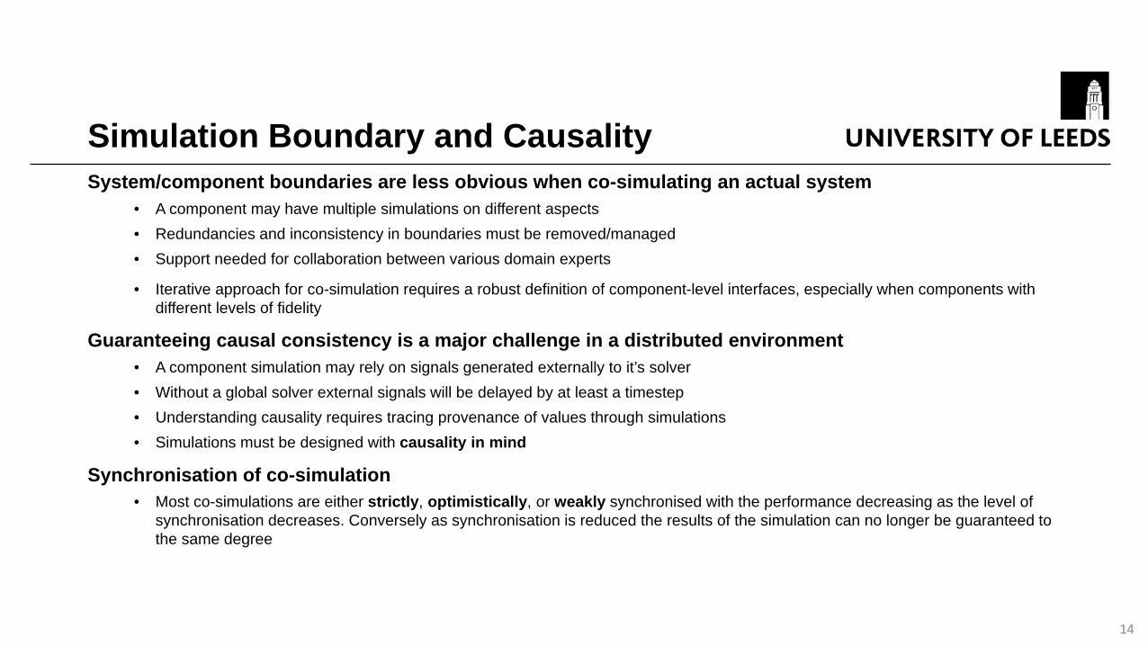
Simulation Boundary and CausalitySystem/component boundaries are less obvious when co-simulating an actual system
• A component may have multiple simulations on different aspects• Redundancies and inconsistency in boundaries must be removed/managed• Support needed for collaboration between various domain experts
• Iterative approach for co-simulation requires a robust definition of component-level interfaces, especially when components withdifferent levels of fidelity
Guaranteeing causal consistency is a major challenge in a distributed environment• A component simulation may rely on signals generated externally to it’s solver• Without a global solver external signals will be delayed by at least a timestep• Understanding causality requires tracing provenance of values through simulations• Simulations must be designed with causality in mind
Synchronisation of co-simulation• Most co-simulations are either strictly, optimistically, or weakly synchronised with the performance decreasing as the level of
synchronisation decreases. Conversely as synchronisation is reduced the results of the simulation can no longer be guaranteed tothe same degree
14

CouplingTypical approaches to coupling of simulations
• Code-based, typically defined in C or C++ uses one of the available APIs• Graphical using a workflow/flowchart/circuit design style
Manual integration always required• By writing code or wiring up a diagram
- prone to errors • Complexity of models
- with 100s to 1000s of interaction points
Example (with only a few interactions)• “SignalConditioning”• to handle the challenge of incompatible signals• Harder coupling when “Pedal” labelled as “Throttle”
15

Continuous Co-SimulationContinuous time vs discrete time
• Algebraic using ODEs
Continuous simulations• “initial value” – using a numerical ODE solution • “algebraic loops”
- where a signal loop exists with only direct feedthrough within the loop” i.e. the output depends on the value of the input which depends on the value of the output
Challenges: when using solvers for these problems• e.g. lack of stability as the solutions fluctuate/oscillate around the actual value• Current solutions: keep the entire simulation within a single tool, and then be able to use ODE solvers such
as Runge-Kutta methods, which doesn't scale• Or one must be able to iterate over the co-simulation, which most tools don't support
16

Differing Time-Step IntegrationIndividual simulations have differing representations of time
• Logical time - the time being modelled by the simulation. Higher fidelity simulations will tend to model shorter period of logical time
• Execution time - the time taken for the simulation to run or perform a logical time stepe.g. a simulation may take 30s to run a simulation modelling 1s or conversely take 1s to run a simulation modelling 30s
Integration of individual concepts of time in different simulations • Requiring a mixture of extrapolation and interpolation• Current solutions (zero & first-order holds) may result in instantaneous value changes
when the next value is observed and is different than the predicted value• Current solutions require the engineers to understand the issues of timing integration
and manually apply their domain expertise
17
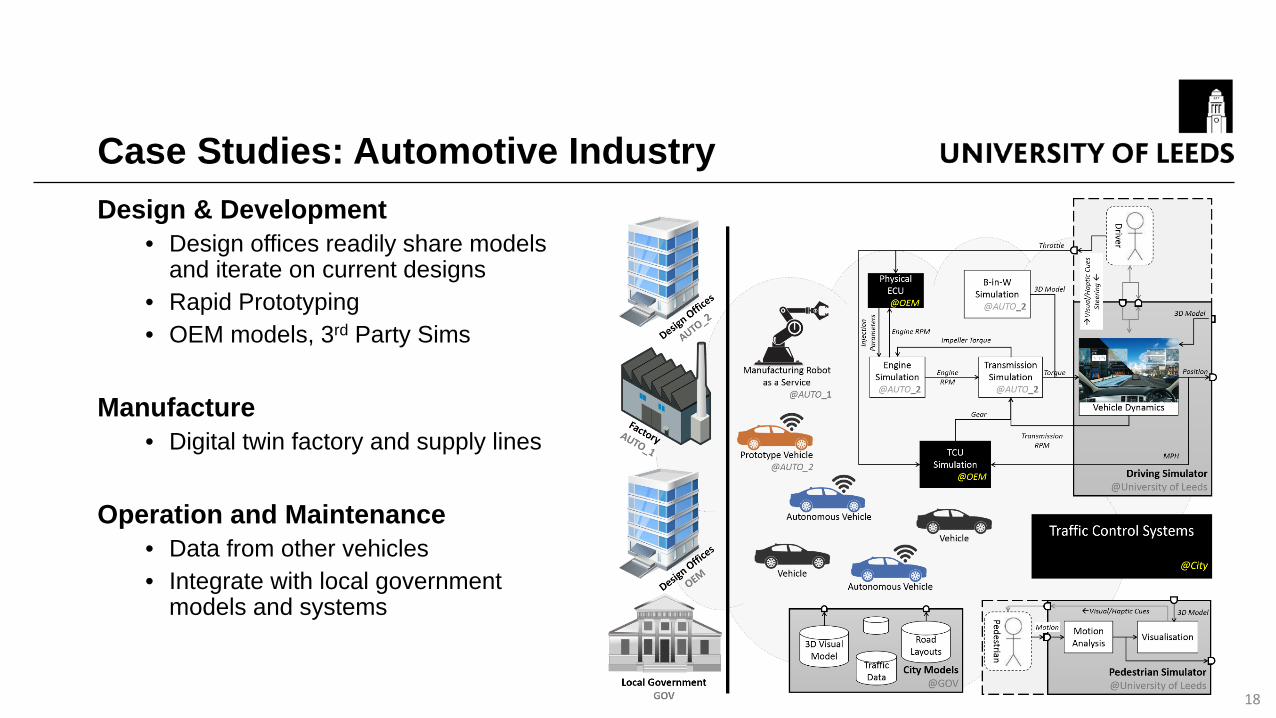
Case Studies: Automotive Industry Design & Development
• Design offices readily share models and iterate on current designs
• Rapid Prototyping• OEM models, 3rd Party Sims
Manufacture• Digital twin factory and supply lines
Operation and Maintenance• Data from other vehicles • Integrate with local government
models and systems
18

Case Studies: Automotive Development
Low
Medium
High
19

Case Studies: Driving Simulator
Throttle
Brake
Engine VehicleDynamics
TCU
Transmission
Micro-Service
Service
Leeds Driving Simulator
20

Case Studies: CITIUSResearch new technologies to command, control and interoperate autonomous vehicles in military operations.
21
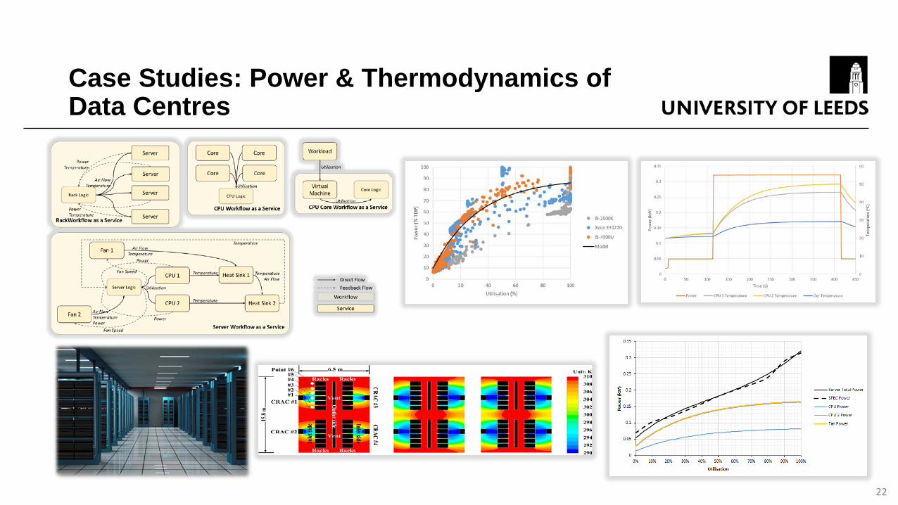
Case Studies: Power & Thermodynamics of Data Centres
22

Conclusions and Next Steps• Growing need for integration of simulation• We already do this, lets do it better!• Internet of Simulation, a possible solution but:
• Need increased support from standards and vendors• Design simulations with reuse in mind
• Agile Systems Engineering• Example case studies
23


