THE ANALYSIS AND DESIGN
OT ~
FOURTH GENERATION LANGUAGE
A Thesis
Presented to the
Division of Mathematics and Physical Sciences
EMPORIA STATE UNIVERSITY
In Partial Fulfillment
of the Requirements for the Degree
Master of Science
by
Karen I Craft
May 1988
AN ABSTRACT OF THE THESIS OF
Karen I Craft for the Master of Science Degree
in Mathematics presented on March 1988
The Analysis and Design of a
Fourth Generation Language
The enclosed thesis contains a study of the first
three phases of the software engineering process as applied
to the project of creating a fourth generation language
(4GL) Initially the 4GL is defined Three levels of
users are also defined - the software engineer who creates
the 4GL the application developer who uses the language to
develop a specific application program and the final endshy
user who operates the application program created with the
4GL Incl uded are schematic diagrams to show the logic
flow of the language Sample screens are also included to
show the results of using the language for an application
The fourth generation language automates the code writing
process wi th modul es to handl e menu systems data entry
screen handling keyboard handling validity testing error
handling data access and searches report generation
printer control fi le and index management and internal
data management of buffers pointers and system functions
463000 DP OCT 21 e~
oJdd
--=== CONTENTS ===-shy
I - Introduction 1
II - Analysis 18
III - Design 18
IV Screen Design 29
v Developer Interface 41
VI - Code Design 48
VII - The Library 57
VIII - Testing 66
IX - Summary 68
Bibliography 78
--=== TABLE OT FIGURES ===-shy
FIGURE 1 - Main Menu Screen bullbullbullbullbull 30
FIGURE 2 - IO Screen Format bullbullbullbullbullbullbullbullbullbull 32
FIGURE 3 - Sample Entry Screen bullbullbullbullbullbullbullbullbullbull 33
FIGURE 4 - Sample Coding Menu Screen bullbullbullbullbull 34
FIGURE 5 - Sample Code Screen bullbullbullbullbullbullbull 35
FIGURE 6 - Application Specific Help Screen bullbullbullbullbullbull 36
FIGURE 7 - 4GL General Use Help Screen bullbullbullbull 36
FIGURE 8 - Data Search Menu Screen bull bull bull bull bull bull bull 37
FIGURE 9 - Sample Data Search Screen bullbullbullbullbullbull 38
FIGURE 10- Sample Report Menu Screen bullbullbullbullbullbullbullbullbullbull 39
FIGURE 11- Sample Report Format bullbullbullbullbullbullbullbullbull 40
FIGURE 12- Sample Report Format bullbullbullbullbullbullbullbullbullbullbull 46
FIGURE 13- System Structure Diagram bullbullbullbullbull 51
FIGURE 14- System Structure Diagram (continued) bullbullbullbull 52
FIGURE 15- System Structure Diagram (continued) bullbull 53
---=== I INTRODUCTION ===-shy
Overview --- This document contains a study of the
first three critical phases of the software engineering
process as it is app 1 i ed to the proj ec t of crea t i ng a
fourth generation language Ini tiall y it is necessary to
provide some background information which defines the terms
so-f tl4lt3re engineer i ng CASE ( Comp u t er Aided Sof tware
Engineering) and 4~ (Fourth Generation Language)
Understanding these terms will aid in better understanding
the goals of the project
Background Information --- Within the past few years
the ever-changi ng mi cro-compu ter sof tware market has
presen ted many new probl ems to sol ve I n the wor 1d of
value-added computer retailers (VARS) specific Rtarget
markets R have become the emphasis such as medical dental
retai 1er inventory accounts receivabl e or general 1edger
applications to name a few Off-the-shelf software is too
general for these spec ia1 i zed fields therefore custom
sof tware becomes a necessity Wi th the recent flood of
these market needs the software engineer is forced to
develop more eff i c i en t methods to produce the vol ume of
Q9 2I Introduction
applications needed Tom Adams team 1eader at ASCI I
(Automated Software Concepts International Inc) and the
designer of GhostWri ter describes the changes required in
the programming approach at ASCII middotWe had to find a
competitive - and affordable - way to do custom software
We decided to develop a package that automated the code
1writing process H Custom programmers find it necessary
to increase productivi ty and coding efficiency to
standardize their applications for maintenance efficiency
and st ill retain versatility Continuity from one
appl ication to another keeps the maintenance and training
effort to a minimum
Software Engineering --shy
Software engineering is not just a matter of wr it i ng code bull bull bull The sof tware engi neer i ng li-Fe cycle involves a more or less standard sequence of phases At the outset of a software project a set of requirements are gathered describing the objectives that the software must satisfy Next is an analysis of the requirements exposing important patterns and structures These are called the design specifications
At th i s poi nt sof tware desi gn begi ns Usually a schematic design phase precedes detailed design Upon completion of design code is wri tten --- this is the implementation phase -shy- followed by testing and l11dintenance
I - I~duction --- 29 3
Sof tware engi neer i ng therefore i nvol ves the foll owi ng
phases in the life cycle --shy
1 - Requirements - gathering the objectives 2 - Analysis - exposing patterns and structures 3 - Design - schematic and then detailed design 4 - Implementation- actual coding 5 - Testing - verifying correctness 6 - Maintenance - correcting updating revising
Advances in technology and techniques to improve the process have not kept up wi th the demand for new software or perhaps programmers have been too busy to 1earn them Whatever the cause many programmers have apparently decided to skip designing software in favor of just getting the job done R I t can always be fixed later R seems to be the attitude of the day
Programming is costl y enough when it is done correctly this haphazard rush to completion only adds to the costs both in maintaining the software a~ in producing truly useful applications
In a software engineering project the greatest effort is expended in the later phases of the life cycle Coding testing and maintenance take far more time than analysis and schematic design
In contrast decisions made early in the life cycle have the greatest impact on the quality and maintainability of the resulting software Studies have shown for example that errors detected during [the] requirements [phase] are correc ted in far 1ess time than errors detec ted during implementation or maintenance
I n other words the 1east effor tis i nvesied in the most important phases of the life cycle
I - Introduction --- 29 4
CASE --- A CASE produc tis any compu ter tool that
assists any phase of the software engineering process The
defini tion is qui te 1 iberal due to the fact that software
engineering itself is a broad activity -Any computer tool
that assists in the process can legitimately claim the CASE
label 2 MCASE tools perform analysis and design code
generation testing and maintenance Few i f an y do all
these things however- 3
CASE can partially automate the coding and testing
phases This is the goal of application builders and code
generation products CASE will also promote standardshy
ization and support better and more accessible
documentation resulting in lower maintenance costs In
this way CASE will in principle redirect resources to the
cr it i ca 1 phases of requ i remen ts anal ysi s and schema tic
2designshy
Through extensive user surveys (published in CanputerAided So-ftAlt3re Engineering CASpound) BTR [Business Technology Research of Wellesley Hills MAl determined that most users have been emp 1oyi ng CASE tool s for on 1y the past 18 to 24 months [as of March 1988l
CASE tools break down into two segments design automation and programming Programming tool s are primari 1y avai labl e on IBM mainframes at prices in excess of $100OOO according to Bayer [David Bayer an industry analyst with Montgomery Securities San Francisco CAl The
I - Introduction --- eg 5
trend however is to less expensive products that can run on micro and minicomputer workstation platforms He expects more sophisticate2 programming tools to appear this year [1988]
The proj ec t inc 1uded herei n is fo11 owi ng the trend toward
the micro market
The CASE definition includes two distinct
technologies Front-end or upper-cd-se tools include the
ana1ysi sand desi gn ai ds B3ck-end or lower Cd-se tools
inc1 ude app1 ication generators Th i s p r oj ec t centers
around the back-end or lower case tools which are also
labeled 4GLs or Fourth Generation Languages
4GLs -These application generators assist the
later phases of the [software engineering] life cycle from
detai 1ed design through coding testing and maintenance
They focus on process format and documen ta t i on
2disciplines not information or project managementshy
A 4GL is ac tua 11 y a type of CASE bu tis more easi 1y
thought of as a subset of the CASE technology and also as
the paren t of the CASE In its broadest sense it is the
the back-end or lower CASE tool mentioned above
As a response to many new needs four th genera t i on
languages (4GLs) are becoming more prevalent and are
quickly replacing third generation languages (3GLs) such as
I - Introduction --- Q9 6
BASIC PASCAL COBOL FORTRAN etc A 3GL requ i res the
application programmer to specifically use the language to
tel I the compu ter how to do every detai 1 of each task
Using a 4GL the programmer need only tell the 4GL program
what to do This is due to the fact that a 4GL is an
organized collection of pre-written code which contains
abou t 90 of all s tandard managemen t code needed f or all
applications Just as an operating system is a collection
of standard 1ow-I evel menial tasks that all users need
such as device management character manipulation screen
management etc the 4GL contains a higher 1evel
collection of management macrosmiddot that automate data fi Ie
record fiel d screen and report management tasks The
app 1 i ca t i on programmer no longer needs to II re-i nven t the
wheel II All programs developed wi th the 4GL then become
standardized in these tasks and all standard or common
tasks are handl ed the same from one app 1 i ca t i on to the
next A 4GL does the same thing for application programs
that the operating system does for hardware onl y at a
higher level The operating system standardizes the
interface between the programmer operator and hardware
devices and the 4GL standardizes the interface between the
programmer operator and the appl ication A truel y
I - Introduction --- --- pound9 7
efficient 4GL will automate as many standard or normal
tasks as possi bl e All that is left for the appl ication
programmer to do is to add the non-standard tasks specific
to the application
4GLs have al so been descr ibed as Ha con t i nued
ev 0 1uti on of languages H4 Ha specialized language that has
been designed to do a specific function H4 as being Hable
to do a task with roughly one-tenth of the code needed in a
3GL H 4 bull HWi th 4GLs the prec i se ins truc t ions have been
automated The language has been demystified 4GLs employ
a dialogue between user and computer interacting to solve
the users probl em The focus is on the task not on the
5computer H
Many 1evel s of 4GLs ex i st from simp 1er 4GLs wh i ch
allow an end-user to create a simpl e database to powerful
system-house 4GLS used by software engineers The
difference between the two is the degree of flexibility and
of the de ta i 1 allowed i nits use The simpl e 4GLs allow
for only very basic standard functions while the powerful
4GLs allow the versa ti 1 i ty of adding the unusua1
nonstandard func t ions when needed usi ng the host 1anguage
and the extended DmacroH language of the 4GL itself This
study considers the later the powerful system-house 4GL
I - Introduction --- --- 29 8
ASCII the producers of GhostWriter define their
product as (1) an automated code writing process (2) an
application generator (3) an ap p I i ca t i on development
4system and (4) a CASE (Computer Aided Software
5Engineering) product for program development The
engineering approach contained herein echoes these four
def i nit ions and consi ders the 4GL as an ex tensi on of the
Pascal language with the creation of 8macro 8 procedures and
functions for system-house use to create rela ti onal
database management applications
Summary In summary this document contains the
study of the first three cri tical phases of the software
engineering process (the requirements analysis and design
phases) for a four th generat i on language Br i ef I y th i s
involves a subset of the CASE technology called the
appl ication generator technology (al so call ed back-end or
lower CASE) It can also be described as an automatic code
generator wi th screenreport creat i on dictionary
definitions data base management procedural language and
functional integration as described in 8The James Martin
Productivity Series82
The creation of a fourth generation language (4GL)
I - Introduction --- ~ 9
itself requires quite an involved programming project The
ASCII programming team spent three-and-a-half years work on
1their GhostWriter written in Turbo Pascal This document
analyzes the type of product produced by this company
--=== I I ANALYSIS ===-shy
A high-level analysis at this point involves sever-al
d i r- ec t i on s bull The fir-st step is to define the user-s and
their- r-espective needs
The User- --- Defining the needs or- r-equir-ements of a
softwar-e pr-oject also initially r-equir-es defining the
user- In or-der- to avoi d any confusi on thr-ee ter-ms ar-e
used consistently within this document -- shy
(1) The softwar-e enQineer- who cr-eates the 4GL (2) The application developer- who uses the 4GL (3) The clientend-user- or- oper-ator- who uses
the application cr-eated with the 4GL
In this situation the application developer- (also known as
a system developer-) is the user- of the 4GL however- while
using the 4GL this developer- pr-oduces appl ications for- a
var-iety of clients or- end-user-s This r-equir-es that the
4GL be wr- it ten in such a manner- as to a 11 ow for- many
di ffer-en t var- ia t ions in database app 1 i ca t ions Ther-efor-e
analyzing the needs of the application developer- also
involves analyzing the needs of as many client applications
as possible The application developer- becomes the Dmiddleshy
manU for- the client the final application end-user- Thus
two 1evel s of ana 1ysi s ar-e consi der-ed the needs of the
II - Anallsis 29 11
application develope~ and the needs of the develope~~s
clients
James Hughes explains a standa~d app~oach to the
analysis p~ocess --- At p~oject initiation a p~oject team
- consisting of systems analysts and use~s assigned full
time to the team - must define the p~elimina~y requirements
of the system
Traditionally at this point analysts would interview
dozens of users to determine requirements This often
produces a long list of wants and needs that are difficult
to analyze and use for system development
A better approach is to involve a few experienced
users in the definition of preliminary requirements and
major system externals - such as menus data-entry sc~eens
on-line query displays and reports These system externals
should then be incorporated into a horizontal prototype
middotUsers can review and rank the functions in the
horizontal prototype to determine which functions should be
8 au tomated
Software En9inee~ and Application Developer Needs --shy
The software engineer (the 4GL developer) and appl ication
developer (use~ of the 4GL) have much in common They are
eg 12II Anal lsi s
both developers for a cl ient The software engineer
creates general applications for the application developer
and the application developer creates specific applications
for the clientend-user As mentioned in the introduction
several quality requirements include increased productshy
ivi ty code efficiency maintenance efficiency standardshy
ized appl ications and versati 1 i ty Further clarification
is now needed
Increased productivity involves the production of an
application in less time than with previous methods This
is easily measureable by keeping time logs on all projects
however one must remember that not all projects are
created equal
Maintenance includes updating the system for changing
needs correcting errors and adding new capabi 1 i ties In
most organizations it is estimated that 78 of the
programming is dedicated to maintaining existing systems
Wi th 4GLs 78 of the time is spen t on or i gi na 1 codi ng and
38 on mai n tenance 4 A rat i 0 of 88 - 28 is the mi n imum
acceptable goal of this project with the ultimate goal of a
95 - 5 ra t i o The appl ication developer is required to
provide parameters to the 4GL to define the data file
II - Anal~sis --- 29 13
structure entry screens and report formats In other
words the majority of the time for using the 4GL is spent
in designing the appl ication database as is necessary in
any application however little additional time is needed
beyond that stage
Efficiency involves three major areas of concern
speed memory and maintenance efficient code Speed
eFficiency can be measured wi th timing tests The 4GL
developer must consider disk access time when using
overlays and managing data files Both the software
engi neer and the app 1 i ca t i on developer have access to the
use of in 1 i ne and ex terna 1 code to speed up processi ng
H~ory efFiciency can also be implemented using inline and
external code Due to the fact that the constraints of the
proj ec t inc 1ude use of PCXT equ i pmen t it is necessary to
keep the code as compact as possible The 4GL developer
can compare the memory required by one algorithm over
another in order to determine the memory efficiency
~intenance eFFiciency is included here as the top priority
requirement It is not a truely measurable feature
However all desi gn for the software engineer and
application developer must have an under 1yi ng purpose of
29 14II - Anal~sis shy
being easily updateable as new needs surface This becomes
a Y gray area- An elaborate algorithm may be quite
efficient time- and memory-wise but too difficult to
maintain because of a lack of readability Readability is
based upon the opinion of the programmers and dependant
upon their expertise Readability and maintenance have top
priority over speed and memory
Standardi zing app 1 i ca t ions is impor tan tin two maj or
ways From the programming and maintenance point of view
standardized al gori thms prevent reinventing the wheel and
save much development time From the appl ication
developers point of view this is the major purpose fo
usi ng the 4GL The app 1 i ca t i on developer no longer needs
to be concerned wi th how the app 1 i ca t i on handl es menus
input keyboard handling validity testing and error
handling output and printer control screen functions
color coding and windowing search routines buffers
pointers system functions or even the processing of data
i ndi ces and f i 1e managemen t bull These are tota 11 yin the
control of the 4GL The application developer then is
concerned wi th whtilt the system must do for the special
application and not how it does it
II - Ana 1~s i s 29 15
Versatility is a quality that can really only be
measured wi th time Due to the vast range of specific
application requirements of clientend-users it is
impossible to foresee and allow for all possible features
that might be needed by the appl ication developer After
the major design requirements are defined a further
requirement is to allow for direct appl ication programmer
code wi thin the program to add the non-standard features
Standard code is code that is protected and not allowed to
be changed by the application programmer The requirement
of versatility is provided for with code files accessible
to the application developer that contain stubbed
procedures in which any unforeseen specific application
requirements are coded by the application programmer
Standard Pascal commands and an extended language set of
4GL macros ltdescribed in more detai 1 later) are avai lable
to the application programmer as the specific code is
added The standard code files created by the 4GL
developer are designed to handl e 89 - 99 of all
application needs These include automatic handling of the
functions listed in the middotStandardizing Appl icationsmiddot
paragraph above Additional code added by the application
developer is typically 1-5 of the total
II - Analysis --- --- Po 16
ClientEnd-User Needs --- Quite often the clientendshy
user is a novice wi th respect to computer operation All
design is directed to the needs of the new computer user
As mentioned earlier maintenance is the top priorty of the
entire project but consistent user-interface is the second
priority Every move required from the operator is to be
thoroughly prompted In more specific terms this first of
all requires a stdnddrd screen Id)oUt in order to assure
the operator that all prompts will be consistently seen in
the same format throughou t the en tire program opera t i on
Color coding aids in prompting the user also Help screens
are avai lable at all times Ddtd input is prompted at the
field level with data type data limitations and field
descriptions All data is checked for fIlt3liditv and any
required or coded fields are tested before saving the
record to the database S~rches of the database allow for
mul tiple searches for any limitations on any or all fields
available in the file The first phase of development
allows for searches of concurren t search cr iter ia however
the second phase allows for OR NOT XOR and wi 1d card
searches Report Forl11dts allow for col umnar formats page
numbering column totals and counters Printer
attributes such as bold and underline can be embedded in
II - Analysis --- --- P9 17
report formats User-entered subtitles are also allowed
Summary I n summar y the fun c t i on s t ha t wi 11 be
automated include
1 - a menu system 2 - data-entrydisplay screen functions
(IO screens) color coding windowing
3 - data entry keyboard handling validity testing error handl i ng
4 - data access (searches) 5 - report generation (output)
printer control 6 - file management
indices saving deleting reading data file
7 - internal data management buffers pointers system functions processing of data
--=== I I I DESIGN ===-shy
The top 1evel design concen tra tes upon the usershy
interface The lower 1evel of design concentrates upon
the mechanics and maintenance aspects This chapter will
discuss the top level designing phase in terms of general
requirements and of the functions to be automated
Phased Development --- Development of this project
is designed for two major phases The first phase uses
Turbo Pascal 3x BCD with the top priority features The
second phase uses Turbo Pascal 4 and adds the more
detailed features described in the following
System Requirements --- Design begins with the
declaration of the constraints This project is to be
impl emented on IBM PCXTATs or compatibl es (XTATs are
preferrable) with DOS 31 or higher and 328K of RAM A
hard drive is recommended and mono CGA or EGA monitors
are supported The application developer is required to
use Turbo Pascal 3x in the first phase of development and
as soon as version 4 is shipped the second phase will use
it as its base
III - Design IUl 19
Initialization --- A parameter passed in with the
call to execute the program declares to the program where
the data files are located ie the drive and subdirectory
specifications This allows the operator to keep sets of
files within separate subdirectories Once loaded the
ini tial ization of the appl ication program created by the
4GL includes an option for immediate update of fi les and
the ini tial ization of the date Exit from the program is
possible even from this point A personalized logo
screen desi gned by the appl ication developer then
appears to declare the program name and any copyrights and
dates needed Pressing a key continues into the main menu
screen
Menus The main menu for the entire appl ication
created by the 4GL includes a 1 ist of installed database
applications For example a simple menu may include --shy
e = Codes 1 = Chart of Accounts 2 = T~ansactions
3 = Audi t Trai 1
Each menu sel ected resul ts in the use of the same screen
1ayou t descr i bed in more detai 1 1a ter When a menu i tern
is sel ec ted the appropr ia te f i 1es are opened the IO
III - Design 29 20
screen is created and the file and field definitions are
initialized
Command Line Once within a menu selection a
commandline appears at the bottom of the screen Two
forms are used The first allows adding and updating of
records and the second allows only reading of data ---
MenUj AddUpdatej FindDataCINtj RtpOltj PgUpj PgOn ---) enuj FindDataCINtj Reportj PgUpj PgDn ---)
Phase 2 includes security password options which allow for
readwri te access or read only access therefore
determining which commandline the end-user will see
IO Screens --- Data entry and display (for browsing
through a search buffer) screens are the same Standard
IO screens contain the following
1 - the menu title 2 - the current mode of operation 3 - a message area for errors and how to exit 4 - a data entry area 5 - a comrnandline area 6 - a field-level prompt area 7 - an input prompt for data entry limitations 8 - a status line including --- the number records in the curren t f i 1es the number of records in the search buffer the record number of the record curren t 1y bei ng en tered or viewed
II I - Desi 9n --- 29 21
Help Screens --- Help screens are constantly
available by pressing the F1 key Phase 1 help screens
inc 1ude user-spec i f i c i nforma t i on such as accoun t i ng
aids and a user manual displayed sequentially in a
circular list as the space bar is pressed Phase 2
screens allow for going to specific pages in the on-screen
manual for scrolling forward and backward sequentially as
desired and allows for context-sensitive help The
standard user manual is pre-installed however this manual
is accessible to the application developer for editing
Data Entry is standardized with IO screens defined
by the application developer All data is entered within
these screens and also displayed within them when in
browse mode to page through a set of records in a search
Data entry is also dependant upon file definitions defined
by the application developer using parameter tables File
sizes access codes indexing and field definitions are
contained in these tables Data entry in a field uses the
field definition to determine data type field length
validity tests and its location within the record Each
field has field-level prompts displayed as the field is
entered by the operator
II I - Desi gn --- --- eg 22
Phase 1 includes data types of string integer BCD
real byte date and character Automatic sequential
f i el ds (such as sequen t ia1 i nvoi ce number i ng) and defau 1 t
fields are supported A key click option is available for
keys pressed A lookup fac i 1 i ty is bu i 1 t-i n for coded
data fields as explained in the next section on the
middotCoding Systemmiddot Validity tests are performed at the
field level Coded fields are allowed which require entry
of only preinstalled codes Numeric data is tested for
minimum and maximum limits String data entry is not
allowed beyond its maximum length limit Date entries are
also tested for val id dates When an entry is executed
usi ng the FlO key the record is tested for the ex i stence
of required fields If the record is acceptible it is
recorded and any updates to related files are also updated
at that time such as updates to chart of account totals
when a transaction is entered
Phase 2 adds data types for telephone numbers zip
codes social security numbers time and short dates
(mmdd)
II I - Design 29 23
Coding System --shy Due to the fact that it is storage
efficient to use codes for some data fiel ds a standard
for all applications is a built-in coding system Menu 8
is reserved for Codes This menu selection allows the
initialization of a coding library which contains lists of
)i available codes used in the data entry of the entire
t ~ program All coded fiel ds used throughout the program
reference th i s code library to test the va I i di ty of the
data entry for that field Therefore all codes must be
~ i entered in the coding library before they will be accepted
as valid data in the coded data fields No duplicates are
( allowed An example would be codes for source documents
in a transaction such as middotCK for check or IN for an
invoice These codes are indexed and quickly accessible
at any time during data entry ltadding or updating) by
pressing the F2 key A pop-on window lists the installed
I~ codes and their descriptions in alphabetical order and in
a circular I ist for paging through The operator then
returns to the data entry from whence he came Once a
code is used as a reference in a coded data field that is
saved to a file the code is flagged and will not be
allowed to be deleted to guarantee that it can be
referenced by the coded field later
Design --- --- pg 24
Data Searches --- A data search menu includes a
numbered 1 ist of all the fields in the records involved
wi th the curren t menu selection The end-user has the
op t ion to se1ec t an~ or all numbers of the fiel ds for
which he wishes to request concurrent special criteria (a
logical AND search) After selecting the proper fields
the end-user is prompted for the special search cri teria
Str i ng searches are case i ndependen t and allow for two
search type options -Begin-End B searches locate data
matching and between a user-input beginning string to an
ending string Data is matched from the beginning of the
data fiel d I tallows for a search such as all names
beg inn i n g wit h ~ a ~ to m -Within- searches locate all
data fields which contain the user-input string wi thin
them Numer i c and date fields allow the user to input
minimum and maximum limits on the search
Searches involving an indexed field will be
imp 1emen ted usi ng B-tree index i ng and other searches wi 11
be sequentially implemented Data search records are saved
in a circular linked list called a search buffer The
search buffer can be used for browsing through the data on
the screen (pagi ng to the prev i ous or nex t record) or to
print out numerous reports Once the search has been
II I - Desi gn 29 25
used the search buffer can be cleared
To see what search cri teria have been used for the
current search buffer the operator can enter D for data
at the commandline A pop-on window will display the list
of cr iter ia used for the search The coun t of records
con tai ned in the curren t search buffer wi 11 be di sp 1ayed
at the bottom of the screen
Phase 2 will add the OR XOR NOT IF-THEN-ELSE and
wi 1dcard searches and al so wi 11 allow for ascending or
descending sorts according to any chosen combination of
fields Search and replace features will be added in this
phase An operator option is available to search for caseshy
sensitive data Ad hoc searches are allowed in this phase
and commonly used searches are saved as standard -macrosmiddot
Data Reports --- Report formats are initialized by
the application developer In phase 1 these will be
imp 1emen ted usi ng tex t f i 1es These forma ts wi 11 inc 1ude
field locations and field numbers Special printer
options such as bold underlining and compressed print
wi 11 be imbedded wi th i n the formats When request i ng a
repor t the end-user is requested to in it ia1 i ze a search
if none exists A numbered list of installed reports is
III - Design 29 26
displayed in menu fashion When the operator selects the
desired report he may opt to have the report format
displayed before continuing This allows the operator to
be sure he has the proper report Counters paging
col umn total s and numeric grouping (by groups of 5 for
example) are available directly through the formats
created by the application developer To implement
control breaks other than numeric grouping the
application developer adds specific code The page length
is set in the repor t format and is the key that
au toma t i ca11 y manages pagi na t i on and the crea t i on of a
title block at the top of each report One line in the
report is required to contain fields from one common file
Phase 2 allows for a more H free form type repor tin
which fields on the same line can be contained in
different data fi 1es Phase 2 uses the 4GL i tsel f to
create the report formats and parameters and also allows a
max imum wi dth repor t of 132 charac ters A mat hema t i ca1
formula or a special logic procedure can be manually coded
by the application developer
Design 29 27
Pr inter Suppor t --- Due to the fac t that there is
little standardization for the many printers on the
market each printer requires its own set of driver codes
for special attributes such as bold underline
compressed 6 or 8 1 ines per inch ital ics and double
wide Printers are supported by a parameter file
containing these code numbers The file is created by the
application developer and allows him to install codes for
for any or all printer interfaces for which he has codes
F i 1e Managemen t --- F i 1e managemen t loll ill be
implemented with a B-tree and indexing system Parameters
wi 11 be suppl ied by the appl ication developer to define
files and their respective fields Restructuring of files
is not allowed however a transfer from one file to
another can be made A re-indexing uti 1 i ty re-indexes
files that have been corrupted It uses the file field
and index defini tions to restructure indices after
renaming the 01 d indices to have as a backup unti 1 the
process has been verified The operator then has the
option to delete the old indices
User Interface --- User interface is well-served by
II I - Design 29 28
the several requirements previousl y mentioned
standardized screens a pop-on code window a pop-on
manual or help window and constant prompting at the field
1evel bull The user wi 11 know that he is expec ted to en ter
data when the color yellow (or reverse video on monochrome
monitors) appears on the screen Even character input
will be prompted by listing all possible characters
allowed in the input Error messages must be preceded by
a beep to si gna1 the user to look ina pre-determi ned
message area At all times the user will have a message
explaining how to exit the current situation The use of
keys will be consistent throughout the application for the
operator Standard key combinations are pre-installed
however these can easi 1y be re-conf i gured by the
application developer with the simple reassignment of key
constants
--=== IV-SCREEN DESIGN ===-shy
Within the next four chapters are the more detailed
aspects of the project This chapter concentrates upon
the IO screen designs used by the data entry routines and
report browsing routines
Standardized screens --- Standardized screens are
not only a benefit to the end-user but also to both the
software engineer and the application developer End-user
interface is of utmost importance due to the fact that
the majori ty of users are novices Bei ng abl e to
consistently find error and status messages and prompts in
pre-set 1oca t ions ai ds great 1yin the opera t i on of the
application program However the major advantage for the
developers is the fac t that all screen handl i ng can be
channeled through one screen formatting module Any
desired changes in the screen layout are made in that one
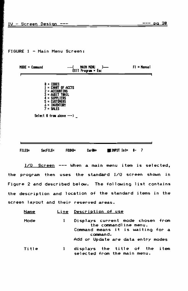
module Figure 1 is an example of a main menu screen from
an application using the 4GL
IV - Screen Design --- 29 38
FIGURE 1 - Main Menu Screen
HODE = Cllllland -( HAIN HENU 1- Fl =Hanual EXIT Prbullbull = Esc
8 =CODES 1 =CHART OF ACCTS 2 = ACCOtMING 3=AUDIT TRAIL 4 =SUPPUERS 5 = CUSTIltERS 6 = ItfJENTORY 7=SALES
Stlct I from about ---)
FILES ScFILE= FO~D= Curllt= bull INPUT Int= - 7
IO Screen --- When a mai n menu item is sel ec ted
the program then uses the standard IO screen shown in
Figure 2 and described below The following list contains
the description and location of the standard items in the
screen layout and their reserved areas
Name Line Description of use
Mode 1 Di sp 1ays curren t mode chosen from the commandline menu
Command means it is wai t i ng for a command
Add or Update are data entry modes
Title 1 displays the title of the item selected from the main menu
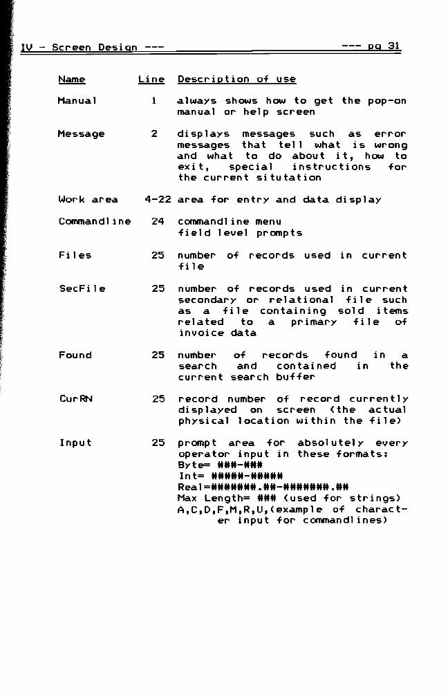
IV - Screen Design eg 31
Name
Manual
Message
Work area
Commandline
Files
SecFile
Found
CurRN
Input
Line
1
2
4-22
24
25
25
25
25
25
Description of use
always shows how to get the pop-on manual or help screen
displays messages such as error messages that tell what is wrong and what to do about it how to exit special instructions for the current situtation
area for entry and data display
commandline menu field level prompts
number of records used in current file
number of records used in curren t secondary or re 1at i ona 1 f i 1e such as a file containing sold items related to a primary fi 1e of invoice data
number of records found in a search and contained in the current search buffer
record number of record curren t 1y displayed on screen (the actual physical location within the file)
prompt area for absolutely every operator input in these formats Byte= - Int= - Real= - Max Length= (used for strings) A C D F M R U ( examp 1e of c harac tshy
er input for commandlines)
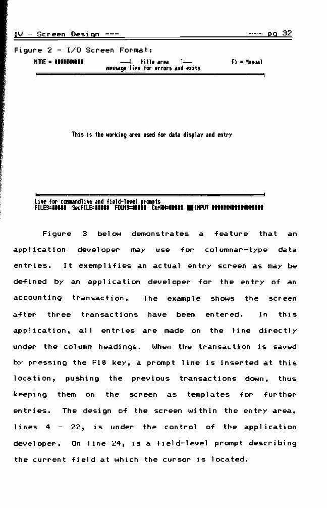
IV - Screen Design --shy eg 32
Figure 2 - IO Screen Format
HODE =1111111111 --- title area l--- Fl =Hanual message line for errors and exits
This is the working area used for data display and entry
Line for commandline and field-level praaptsFILES=IIIII SecFILE=11111 FOUND=IIIII CurRN=11I11 IIINPUT 111111111111111111
Figure 3 below demonstrates a feature that an
application developer may use for columnar-type data
entries It exemplifies an actual entry screen as may be
def i ned by an app I i ca t i on developer for the en try of an
accounting transaction The example shows the screen
after three transactions have been entered In this
application all entries are made on the line directly
under the column headings When the transaction is saved
by pressing the Fie key a prompt line is inserted at this
location pushing the previous transactions down thus
keeping them on the screen as templates for further
entries The design of the screen within the entry area
1 i nes 4 22 is under the control of the appl ication
developer On line 24 is a field-level prompt describing
the current field at which the cursor is located
IV - Screen Design --- Q9 33
Figure 3 - Sample Entry Screen
HODE = Add - ACClHNTIN6 1- Fl = Manual Esc = Canand Line ENTIN F7 = Del i Fl1 = Save bull F2 = CODES
BIT bullbullbullbullbullbullbullbullbullbullbullbullbullbull I CREDIT bullbullbullbullbullbullbullbullbullbullbullbullbullbullbullbullbullbullbullbullbullbullbullbullbullbullbullbull I bullbullbullbullbull
Transact r-- Debit --- r-- Credit -- r SourcDate Acct Mount Acct Mount Doc Nulbtr CGRfnts
l1li7---- ------- ---- - --__ - ___88middot7middot II bullbullbullbullbullbullbullbullbullbullbullbullbullbullbullbullbullbullbullbullbullbullbullbullbullbullbullbullbullbullbullbull
881111 1111 33452 3121 33452 B6 Beginning Bank Balance 8811112 6121 2367 un 2367 CJ( 3241 Insurance Pa~t
Enter YearA10nthlDay as 87 31 5 --- zeros not nussaryFILES 2 SecFILE= FoaD= Curllf= 3 INPUT Byte= 1- 12
On the fourth line above the name of the debit or credit
is printed in the spaces when the respective account
numbers are entered and found to be val id Thi sis a
result of two lines of specific code added by the
app 1 i ca t ion developer Th i s presen ts an examp 1e of wha t
special features can be accomplished with the 4GL
Color Coding --- When the operator sees this screen
on a color mon i tor the data en try area for the mon th is
highlighted in yellow to indicate that this information is
what is to be entered Yellow sayS Hdo somethingH The
two bottom lines also verifiy what is to be entered
light cyan while the current data entry field is yellow
screen is avai lable by pressing the F2 key whi le in the
This
29 34
Ft =Manual
The mode Ft = Manual and
2 = stfPllER CREDIT CODES 4 =ItfJlMORY rATE60RY CODES 6 =SAlEIIN
CurRN= 3 bull INPUT Jot= 8shy 255FOlND=
Entry data that has already been entered is
Secfile=
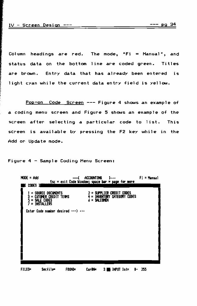
Pop-on Code Screen --shy Figure 4 shows an example of
I
MODE =Add bull CODES ) Esc =exi t Code Win-ire bIr =11 for lOre I
t = SOURCE DOCIKNTS 3 =CUTOHER CREDIT TEAMS 5 =SAlE CODES 7 =INSTALLERS
Enter Code number desired ---) bullbullbull
FllES=
I I
Col umn headi ngs are red
IV - Screen Design
screen after selecting a particular code to 1ist
status data on the bottom line are coded green Titles
are brown
Add or Update mode
a coding menu screen and Figure S shows an example of the
Figure 4 - Sample Coding Menu Screen
-- ------ ------------------------------- -
IV - Screen Design --- 29 35
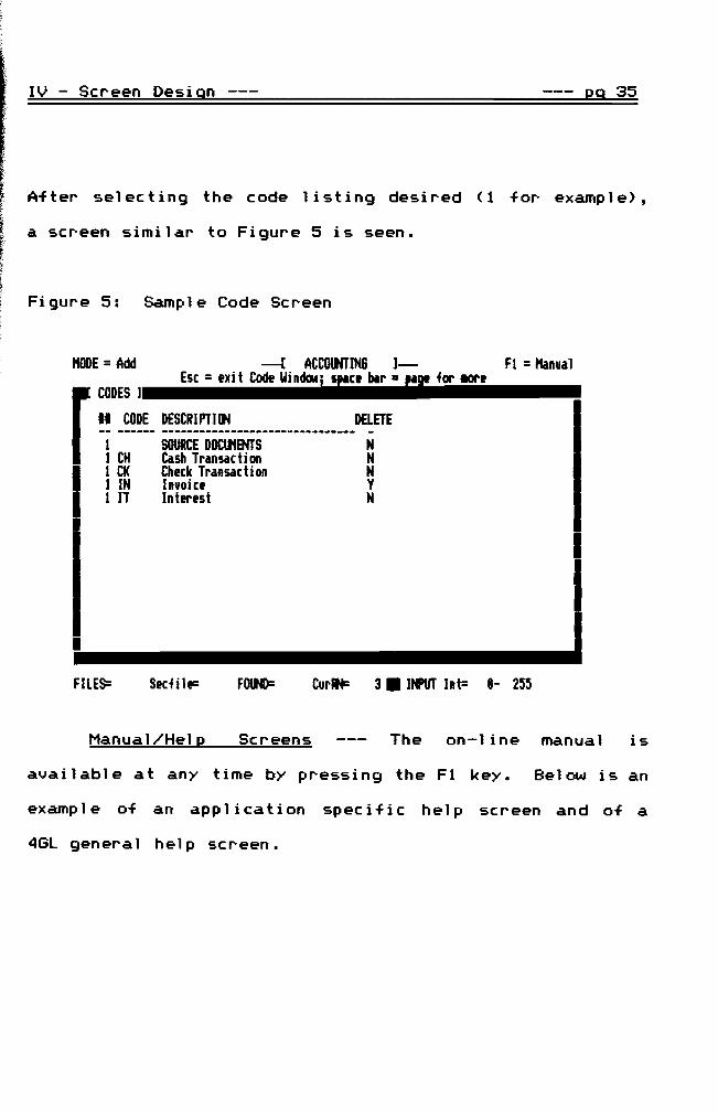
After selecting the code listing desired (1 for example)
a screen similar to Figure 5 is seen
Figure 5 Sample Code Screen
MODE = Add -l ACCOlNTIN6 1- Fl = Hanual CODES] Esc = xi t Code WindcMijC blr = for _or _
r CODE DElETEDESCRIPTl~ 1 SOURCE DOCIl1ENTS N 1 CH Cash Transaction N 1 CK Chck Transaction N I IN Invoic Y 1 IT Intlfst N
bull FILES= Scfi IF F~D= Cur~ 3 bull IIftT Int= 1- 255
ManualHe1 2 Screens The on-line manual is
available at any time by pressing the F1 key Below is an
exampl e of an appl ication specific hel p screen and of a
4GL general help screen
IV - Screen Design --- 29 36
Figure 6 Application Specific Help Screen
HODE = -[ ACCOtHTING 1- FI = Hanual Esc = exit Hanual Windlllj space bar = page for ore
F[ tWIW I II bull ACCOIlflING EQQTI~ _
---- ASSETS I = r LIABILITIES -- r-- EQUITY -----increase Assets Otcreast Assets UtCrNst I IncrNse DtCrease I Increase NIM Assets I AcclII Deprec Paid I Payable Oraliting Capi tal Unexpired Insur I Unearneo FItS PrePaid Expense (Advanced Rev) ItmtE stJttARY Received Paid (tllporary proprietorship)
btcrease Equity I Increase Equit Expenses Revenues Inventory (Btgin)l Inventory (End)Purchasts Sales ContraRlVenue ContraPurchasts
(SalK RetaAl) I (Pur RaA)(SalK Discts) (Pur Disc)
Tran~ort-iR I Uncolltct Accts
Henui AddUpdate FindDataClearj Re~orti PaUDj PaOn ---) bull FILE~ 67 StctILE= FOtH)i 23 urlN i8 bull INPUT ACDFHRU
Figure 7 4GL General Use Help Screen
HOOE= -[ ACCOtHTING 1- FI = Hanual Esc = exi t Hanual Windlllj space bar = page for ore
F[ HINW I bulllin bull SPECIAL INPUT KEYS _
I fIiil IBlcSpc --- Hoves cursor to I--J ~ I Tab I NEXT input field Nlllber Keys at Otletes character L=J Top of Keyboard btfore cursorl ~LY
key used to eait WITH S or NIIILock NlttERIC fields
Ctrl ~uses a scrolling scrttn ~ Press Space Bar to continue
--- WITH TAB moves cursor I IShiftl to PREVIOUS input field I L-J I Deletes character I --- above cursor in
I Alt I text input field (DllI I--J I--J
I I
Menu AddIpdate FindDataClearj Re~ortmiddot PaUDj PQOn --) bull FILE~ 67 Stc~ILE= FOUND= 23 turAN= as bull INPUT ACDFRU
IV Screen Design 29 37
Data Searches --- From the commandline the operator
may select RF R for Find to initiate a data search Figure
8 shows an examp 1e of a data search menu for a Char t of
Accounts application Every possible field is listed and
the operator may select one or all of the fields to search
by If a string field is selected the operator has the
option to select a UBegin-End or RWithin U search as
described earlier Ifanumer i c or da t e fie 1dis
selected the operator is prompted to enter the minimum
and maximum desired in the search
Figure 8 Data Search Menu Screen
ODE = Search --I~RT OF ACCOINTS]shy Fl =Hanual EXIT Search l1tnu =Esc
II SEARCH tINU II
1= ClIIlt 2= NoDlt 3= Acc 4= Acct ~ ~ Dscript6= ~ln Sal 7= Jan Total 8= Fib Total 9amp Har Total 11= ~r lolal
11= Hay Total 12= Jun Total 13= Jan Total 14= Aug Total 1~ Sp Total 16= Oct Total 17= NOli Total 18= Otc lotal 19= IstQtTotal 21= 2nijOtlotal21= 3rdOtTotal 22= 4thQtTotal
Entr I of ittms to b searchd --- bullbull
FILES 48 ScFILE= FOlND= Curlt+= 42 INPUT 1- 22
- ------------------ -------------------- --------------------
IV - Screen Design Eg 38
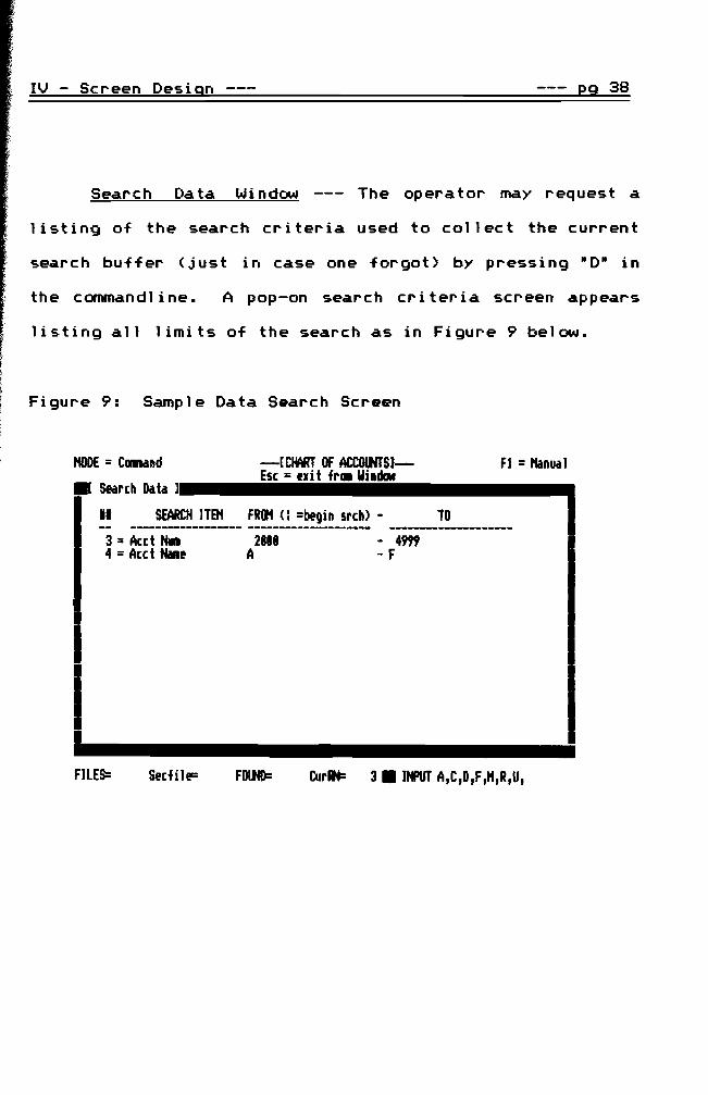
Search Da ta Wi ndow --- The opera tor may request a
listing of the search criteria used to collect the current
search buffer (just in case one forgot) by pressing 8D8 in
the commandl i ne A pop-on search cr iter ia screen appears
listing all limits of the search as in Figure 9 below
Figure 9 Sample Data Search Screen
MODE = ClINnd -[CIMT OF ACCOOOS)- Fl = Hanual
bull Search Data 1bullbullbullbullbullEsc=lXiiltiifrIliCIIwiiidcMbullbullbullbullbullbullbullbullbullbull
II SEARCH JTB1 FRIJt ( =begin srch) - TO
3 =Acct NwI 2 - 4999 4 =Acct tell A - F
I I I~------------FILES Slcfile= FOlJiD= CurRN= 3 INPUT ACDFRU
IV - Screen Design 29 39
Data Reports --- A report may be initiated after a
search I f a repor tis requested and a search has not
been executed then one is autornaticall y requested from
the opera tor A search menu is then 1 isted as in Figure
19 below The operator has the option to see the report
format (Figure 11) before executing the report in order to
be sure it is the correct one Following that the
operator may opt to have the search criteria listed in the
headi ng of the repor t to have page numbers and to send
the report to the screen printer or both
Figure 19 Sample Report Menu Screen
HODE =Rtpor t -[CWIRl OF ACCOOOS)shy FI = Hanual EXIT Search Menu = Esc
III REPORT ~ III
I = Chart of Accounts 2= Account BalanctS - Yearly3 = Account Balances - 1st Quarter 4=Account Balances - 2nd Quarter5 =Account Balances - 3rd Quarter 6 =Account BalanctS - 4th Quarter7 =Account Balances - Beginning 8 = Financial Report
Enter report number --- bullbull
8FILES 48 SecFILE= FOUND= 28 CurAN= INPUT lnt= 1shy
IV - Screen Design 29 40
Figure 11 Sample Report Format
MODE = Report -(CIMT OF ACCOlNTS)- F1 =Hanual - KEY to CINTINUE
I 111111111 ]= ACCOIHT IIAlfWES - 1st lINTER =[ 11111111
Acctl Account HInt 1------------ Totals ------------1
January Flbruary Harch Balances
1st Quarter
iiiii iiiiiiiiiiiiiiiiiiiiiiii iiiiiiiiii Iitlilliii iiialiiiii iilliiiiii 11111 111111111111111111111111 1111111111 1111II1II1 1111111111 1111111111 11111 111111111111111111111111 1111111111 1111111111 1111111111 1111111111 ----- -----------------------shy ---------shy ---------shy ---------shy ---------shy11111 listed 1111111111 1111111111 1111111111 1111111111
=I Page 11111 ]=
FILES= 48 SecFILE= FOUND= 21 CurAN= bull INPUT
-== V-DEVELOPER INTERFACE ==shy
The third priority of a 4GL must be the interface
between the application developer and the 4GL itself The
discussion in this chapter involves the communication
between the 4GL and the appl ication developer in terms of
parameters which define IO screens output report formats
and the database itself ltrecords and fieldsgt The major
time spent by the appl ication developer shoul d now be in
the area of the database anal ysi sand desi gn Once the
design is establ ished the installation of the parameters
involves the following steps
1 - Parameter tables define the base appl ication for A - the file data structure B - the entry screens C - the output or report formats
2 - Specific non-standard code is added using A - the 4GL RmacroR language described later B - the Turbo Pascal language C - in 1 i ne and ex terna1 code allowed through
Turbo Pasca 1 bull
In phase 1 the implementation of the parameter tables is
through tables set up in standard text files Phase 2 uses
the 4GL itself to create these interface definition files
The structure and content is the same wi th each method
The phase 2 method allows for greater security and speed in
reading the files and initializing the file definitions
internally within the program
v Develoger Interface --- 19 42
I n i ti ali za t i on The application developer must
provide parameters for initialization of the system These
include
1 - the location of the data files 2 - The computer type (PCXTAT) 3 - video mode 4 - the filler character for entry areas 5 - the clientend-user name 6 - the program name 7 - the logo screen with copyright and date 8 - the option to have the click sound for keys 9 - a table of the main menu selections and
their related files
The menu title is used in the main menu and when a
selection is made it is used in the title area of the
en try screen The related files are automatically opened
managed and closed during the use of that menu item
IO Screen Defini tions --- Screen defini tions start
wi th the definition of the window environment This
includes
1 - The related file number 2 - The upper left corner location 3 - The lower right corner location 4 - Background color 5 - Foreground color 6 - The window frame type number 7 - The title color
v - Deyeloper Interface --- 29 43
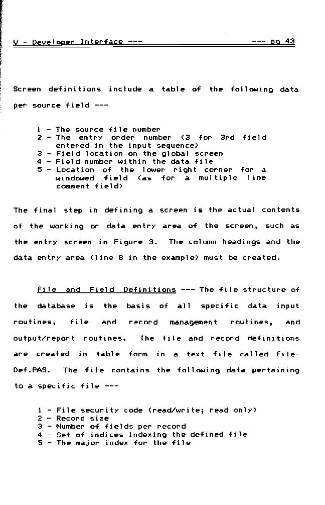
Screen definitions include a table of the following data
per source field --shy
1 - The source file number 2 - The en try order number (3 for 3rd f i el d
entered in the input sequence) 3 - Field location on the global screen 4 - Field number within the data file 5 - Location of the lower right corner for a
windowed field (as for a multiple line c ommen t fie 1d)
The final step in defining a screen is the actual contents
of the work i ng or data en try area of the screen such as
the entry screen in Figure 3 The column headings and the
data entry area (line 8 in the example) must be created
File and Field Definitions --- The file structure of
the database is the basis of all specific data input
routines f i 1e and record management routines and
outputreport routines The file and record definitions
ar e c r ea t ed i n tab1e form ina t ex t f i 1e ca 1 1ed F i 1eshy
DefPAS The file contains the following data pertaining
to a specific file --shy
1 - File security code (readwrite read only) 2 - Record size 3 - Number of fields per record 4 - Set of indices indexing the defined file 5 - The major index for the file
v - DeveloQer Interface --- --- pg 44
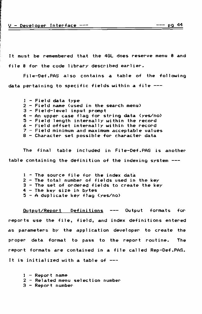
It must be remembered that the 4GL does reserve menu 8 and
file 8 for the code library described earlier
File-DefPAS also contains a table of the following
data pertaining to specific fields within a file --shy
1 - Field data type 2 - Field name (used in the search menu) 3 - Field-level input prompt 4 - An upper case flag for string data (yesno) 5 - Field length internally within the record 6 - Field offset internally within the record 7 - Field minimum and maximum acceptable values 8 - Character set possible for character data
The final table included in File-DefPAS is another
table containing the definition of the indexing system --shy
1 - The source file for the index data 2 - The total number of fields used in the key 3 - The set of ordered fields to create the key 4 - The key size in bytes 5 - A duplicate key flag (yesno)
OutputReport Def i n i ti ons Output formats for
reports use the file field and index definitions entered
as parameters by the appl ication developer to create the
pr oper data forma t to pass to the repor t rou tine The
report formats are contained in a file called Rep-DefPAS
It is initialized with a table of --shy
1 - Report name 2 - Related menu selection number 3 - Report number
v - Develo2er Interface --- 29 45
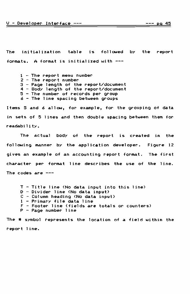
The initialization table i s f 0 1 lowed by the report
formats A format is initialized with -- shy
1 - The report menu number 2 - The report number 3 - Page length of the reportdocument 4 - Body length of the reportdocument 5 - The number of records per group 6 - The line spacing between groups
Items 5 and 6 allow for example for the grouping of data
in sets of 5 lines and then double spacing between them for
readability
The actual body of the report is created in the
following manner by the appl ication developer Figure 12
gives an example of an accounting report format The first
charac ter per format 1 i ne descr i bes the use of the 1 i ne
The codes are
T - Title line (No data input into this line) D - Divider line (No data input) C - Column heading (No data input) 1 - Primary file data line F - Footer line (fields are totals or counters) P - Page number line
The symbol represents the location of a field within the
report line
v - DeveloQer Interface --- e2 46
Figure 12 Sample Report Format
ACCOIHT BALmCES - 4th QIWlTER =[ 1 T ]=D==================== C Acct Account NaIIe October Novuer DecBlber Quarter Bal C ----- ------------------------ --------- --------- --------- --------shy1 bullbullbullbullbullbullbullbullbullbullbullbullbullbullbullbull bullbullbullbull bullbullbullbull bullbull bullbullbull11 bullbullbullbullbullbullbullbullbullbull 1 F F
bullbull11 listed 11F P =[ Page 11111 ]= l1li Source Data bull Line Source Num bull Num FileSub Flds Source Field Arraymiddot---- ------- ---- - -- -- -- -- -- -- -- -- -- -- -- -shy 5 1 6 2 3 15 16 17 21 7 1 4 8151617
The lower source data part of the table above defines the
field content of each input area for the fifth and seventh
lines in the format The example defines the primary file
as the source for the fiel ds 1 isted in the source fiel d
array The fifth line for example has 6 fields which are
numbered 2 3 15 16 17 and 21 input into the format
This works much 1 ike the FORM command in Turbo Pascal 01
like the PRINT USING in BASI C Fi el d number 9 the fi rst
source field on the seventh line represents the record
coun tat the bot tom of each page of the repor t bull If the
page numbering option is selected at the time of the
repor t then the page number wi 11 be pr i n ted usi ng the
format line preceded by the HP Hbull
v - Devel02er Interface --- 29 47
Spec i f i c Code --- A standard 1ogi c for I PO (i npu t
processing output) is embedded into the system however it
is impossibl e to foresee all uses for a program (as the
many versions on the market prove) Therefore the use of
unprotec ted stubbed procedures wi thi n the 4GL system allow
for the application developer to further customize the
final application Turbo Pascal commands inline code
external code and internal 4GL middotmacrosmiddot are available for
the application developer to complete the specific code
The following chapter describes the middotmacromiddot language in
more detail and lists the major middotmacromiddot library procedures
and functions
Th i s sp ec i f iccode sh ou 1d be the on 1y par t of the
final appl ication that would possibly require maintenance
thus greatl y reducing the cost in time and manpower for
maintaining each application
--=== VI CODE DESIGN ===-shy
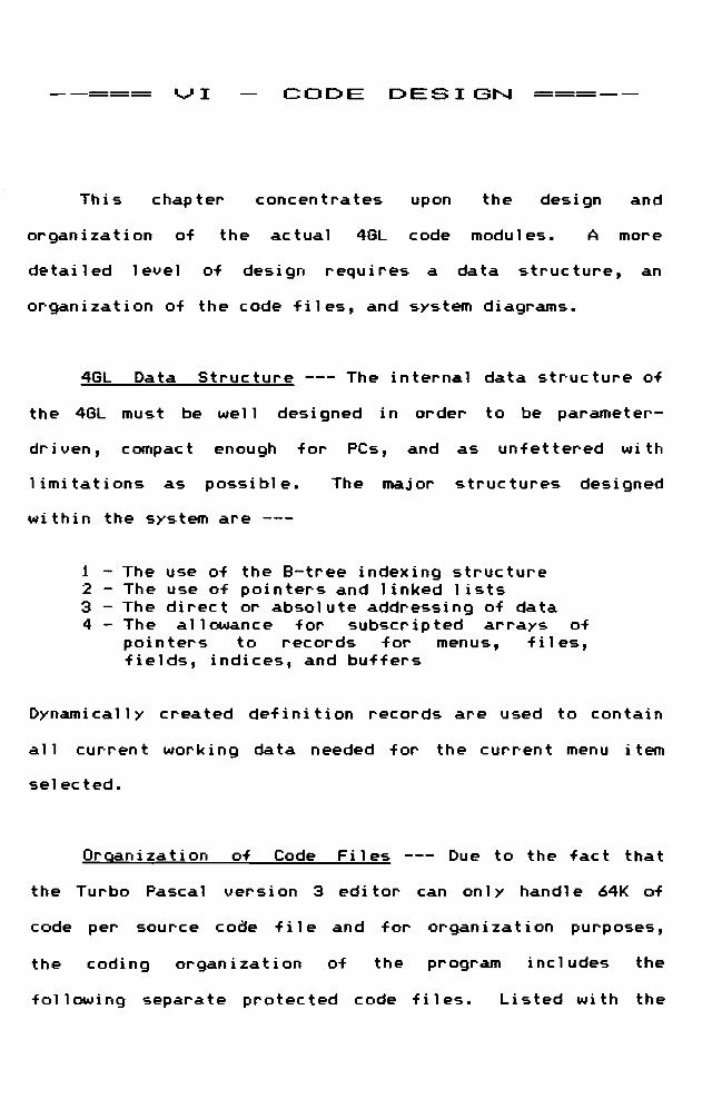
This chapter concentrates upon the design and
organization of the actual 4GL code modules A more
detailed level of design requires a data structure an
organization of the code files and system diagrams
4GL Data Structure --- The internal data structure of
the 4GL must be well designed in order to be parameter-
driven compact enough for PCs and as unfettered with
limitations as possible The major structures designed
within the system are --shy
1 - The use of the B-tree indexing structure 2 - The use of pointers and linked lists 3 - The direct or absolute addressing of data 4 - The allowance for subscripted arrays of
poi n t er s torec or ds f or men us f i 1es fields indices and buffers
Dynamically created definition records are used to contain
all current working data needed for the current menu item
selected
Organization of Code Files --- Due to the fact that
the Turbo Pascal version 3 edi tor can onl y handl e 64K of
code per source code f i 1e and for organ i za t i on purposes
the coding organization of the program includes the
following separate protected code files Li sted wi th the
VI - Code Design 29 49
file names are the contents of each
Type-DefPas - all type declarations and a minimum of global variables
Library Pas - a universal supporting library con tai n i ng i ndependen t modu 1es used by the entire 4GL program
FileMangPas - code for index keys file management
PointersPas - pointer management including queues double linked lists trees and buffers
Support Pas - search menu print search data window get report option data report selection module data input module record management related to
data en try ControlsPas - the 3 major controling modules
which call the supporting modules in Support above
EnterRecord FindData PrintReport
Menu-SysPas - menu system Init-FinPas - initialization and finalization
modules
Also included are two application-specific files accessible
to the application developer These are the files that
contain the stubbed interface modules for the developer
They are
SpeciallPas - UpDateAcct for accounting modules any data entry specific tests
Specia12Pas - any tests required for deletions specific report tests
VI - Code Desi~n --- R9 50
SYstem Diagrams --- The diagrams that follow present
the high-level logic and design in a form simi lar to a
Warnier-Orr diagram Figure 13 contains the most general
logic of the program Figures 14 and 15 continue with more
detail for the Record Menu Keys section in the lower right
corner of Figure 13
r-ii shyilil 111
VI - Code Design Q9 51
Figure 13 System Structure Diagram -- shy
rStt screen I Get data drive ~raleter (Mhere data Mill bt located)I Initialize 5 global variables and flags
I Initialize global ~ointers for buffers files indices menus Read defaults and file definitions
I (currtntly in sequential data file)Initial- ~ Introduction Screen ization I Collect Record Definitions
I Retain origi~l video modej set neM default video lode I Re9uest ilitdiate update yesnol Inltalize linUS file definitions buffers and printer codes
r
IClear ring buffer pointersRe-initiaTize 5 global flags
I Close open files to update disk directorr I Dispose of previous screen definition pOInters
Htnu --4 Hain IUIlU scrnn I Input neM ltAU selection
I ~en neM fi Ie set Create neM entry scrttn and saves current work windows
L
rI Initialize menu variables and pointersI
Control~ Initialize search record Loop I r
II I Initialize quit flagI I r I I I I Read Only HtftujFindlDataiClearjReportjPgUpjPgDnI I ClIIIIc1ndLi ne----- bull I I I ReadAlriteHtftulFindlDataiClearjReportjPgUpjPgDnjI I I AddIUpdateI ClIIIIc1nd Loop---- L L I Tests for mpty filH and buffers
I rPa9fYP Key (get prev record data print fields) I l Case key of ---f bull
I Pa~ Key (get next record data print fields) I bull II
IAlt PagtUp Keys (print prev sub pg Mithin record) I
I
IAlt ~agtDn Keys (print next sub pg Mithin record)
JI bull
I r tI IUpda1e (call II EnterRecord (lUIraquo 1shyI Add (call II EnterRecord (A raquo ~
IRecord Report (ca II II PrintReportgtMenu Key bull
I Clear search buffer
III Fnd data L
rI Window Mhole screen
Finali- -4 Clear screen zation I Video set to original video aode
I Be sure all pointers are nil and files closed L
e represents exclusive or or XOR logic II continued in more detail on follOMing pages
VI - Code Design 29 52
Figure 14 System Structure Diagram (continued)
r r I Cl ear rcord buHrr I IF add --f Print ntry scrttll
Elltr I I Print n~ rcord nUlbrr Rcord --I L
Initializ rcord variabls r
I SIt currtnt ntry iild location iild ltngth and oiist I St input window ii netOfd ior largr txt iilds
Entry --I I rlocat cursor
ISav rntry iild screen middot Initializ iild variablts
loop I Fild looP Print itdiat input prlllpt middot I Input routift according to typ until grt valid an~rr
I PutDatalntoRecord H no qui t flagI 60to nxt tntry iild L
rFI8 Sav (H PostOK i H corrKt data thtn SavtData)
I F9 Archiv ( not currtntly installd ) Cas oi I Functio~ F7 Delt (ii dlltllbl thtn ask again print nxt rcord)Ky I
I F2 Codts pop-on window II Entrl1ab =go to nlt iild in rKord
middot I et t ShiH Tab = go to prtv iild in record DispoH oi ntry rcord buHr
rI Clear rtport iomat buHr I Print installd rport iONlats I Gtt report data I rI I Search critria in output (ytslno)I I Pag numbrs desired (y51no)j ii ys thtn ntr starting pag nUlbrI SIt ~ PauH btwn pagrs (y51no)
printRport1 ~ Chck printr ssag
IChck paOt lngthIncremnf prinf out nUlbrrGtt data rcord
I rI I Print proprr layout iOlllat
Rcord --f Print rcord---- Print record totals H applicablloop I I Print spicing bttwtn rKords ii applicabl
I L I l1ov to nxt search buHrr pointrrL
Chck pagr lngth ior iOMlietd Dispos oi report ioraat buiirr and total buiirsRtplac standard tntry screen 6t data ircn last accsstd search buHrr nodt Print data rcord into ntry screen
VI - Code Design 29 53
Figure 15 System Structure Diagram (continued) -- shy
r Clear search bufftr I r I I Lists all fitlds availablt in rtcord for search I I Input loop of chostn Stt of tlBltnts for tht search I I r I I I StringChar (begin or ~ithin starch) I I I ByttllntegtlReal (iniIUII IIaxiltllll)
ad ~ xxListtttnu-l Input loop of search lili tations--l Oatt (ini IIaXillll) ILL
I r I I 6tt search indtx rtquirtd for starch crittria I I Find first rtcord nUllbtr in search FindData--l Search loop - adds data that INts cri ttria to search bufftr I I Prints first rtcord found or Itssa9t of lNONE F0UND1
L L
Over 1ay Struc ture --- Due to the 1 imi ta t i on of Turbo
Pascal version 3 the management of overlays is necessary
in phase 1 Overlays were determined to be more efficient
in this project than chaining due to the code design It
is also possible for the application developer to create a
batch fi 1e which automaticall y loads all compi 1ed overlay
modules into RAM disk therefore nearly giving the speed of
an EXE program Four overlay files are used in this
projec t
Overlay Design Methodology --- The rules for using
over 1ays can become qu i te i nvol ved when matched wi th the
logic of a program A single overlay file can not contain
modules which call any module within the same overlay code
VI - Code Design 29 54
file including itself because they can not exist in
memory concurrently For memory eff i c i ency the modu 1es
should be of simi 1ar si ze and eac h over 1ay f i 1e sh ou 1d
contain as many individual modules as possible The size
of the largest module within an overlay code file is
reserved in the mai n program memory for swapp i ng in the
called overlay modules To retain speed two or more
overlay modules should not exist in a calling loop to
preven t con t i nuous tradi ng of the modu 1es into the memory
overlay area for each loop
One way to create an overlay system is to create a
columnar table showing the calls or interfaces between only
overlayed modules Global modules are not considered
except for the fact that they must be declared before they
are called The major controlling modules are singled
out In this case that includes the main module which
calls Initialization Menu and Finalization The first
and last are ignored since they are only called once at the
begi nn i ng and the end of the program and therefore can be
located in any of the overlay files conveniently The
con trol loop 1ogi cis then the nex t area to consi der The
con trol loop call s En terRecord Pr i n tRepor t and Fi ndDa ta
which are the three major operations of the entire program
VI - Code Design 29 55
A column is then created for each overlay file in the
design and each column contains the names of the modules in
it To make it easi er to desi gn over 1ays the sof tware
engineer shoul d use color coding wi th high-l ighter pens
For example use green to high-light the modules involved
in the input of data into the program ie those used by
EnterRecord One might use pink to mark all modules
invol ved in the output of data from the program ie those
used by PrintReport Yellow could be used to mark all
modul es invol ved in searches ie those used by FindData
Any other modules might be marked with blue The next step
is to draw color-coded lines from one module to another to
show what modu 1e call s another To comp 1ete the process
each column must be checked to find the dominant module in
other words the one that will be in memory the most The
dominant module should be marked perhaps with red There
may be one dominant module in each column for EnterReport
one for Fi ndDa ta and one for Pr i n tRepor t bull However there
shou 1d not be more than one per each of the three maj or
controlling modules If there is any problem in deciding
between several modules then perhaps a redesign should be
considered
VI - Code Design --- 29 56
By looking for the dominant module in each overlay
file the speed factor can also be considered An overlay
may be more efficient if it is broken down into more
overlays if very many of its modules are called frequently
or are con tai ned in loops that conf 1 i c to I n the diagram
that follows the indicates the dominant module
Ovtlay II Out lay 12 Ovtlay 13 OutlaY 14
HanageFileSet----J
CodeWindCM IlnputData
i
HenulEntryOK HenuIEntryOllt~
Henu2EntryOK J
I
OtleteOK
IEntryOK
I I I I I I II
EnterRecord
Henu
HenulPostOllt HtnulPostOK Henu2PostOllt
~
J
PostOK ---shyI J
f1enu8ScrDtf HenulScrDef ~ CreattEntryScr - f1enu Htnu2ScrDef J
Pointer library - Key library I xxlistHenu I PrintSearchData I FindData SetUp I 6etReportData I ReportSelection J
--=== VI I THE LIBRARY ===-shy
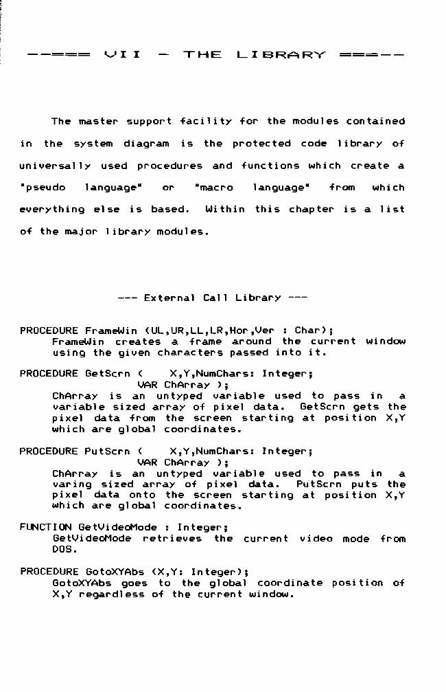
The master support facility for the modules contained
in the system diagram is the protected code 1 ibrary of
un i versa 11 y used procedures and func t ions wh i ch create a
-pseudo language- or -macro language- from which
everything else is based Within this chapter is a list
of the major library modules
--- External Call Library --shy
PROCEDURE FrameWin (ULURLLLRHorVer Char) FrameWi n creates a frame around the curren t wi ndow using the given characters passed into it
PROCEDURE GetScrn ( XYNumChars Integer VAR ChArray )
ChArray is an untyped variable used to pass in a variable sized array of pixel data GetScrn gets the pixel data from the screen star t i ng at posi t i on XY which are global coordinates
PROCEDURE PutScrn ( XYNumChars Integer VAR ChAr ray )
ChAr ray is an untyped variable used to pass in a var i ng si zed array of pixel data Pu tScrn pu ts the pixel data onto the screen starting at posi tion XY which are global coordinates
FUNCTION GetVideOMode Integer GetVi deoHode retr i eves the curren t video mode from DOS
PROCEDURE GotoXYAbs (XY Integer) GotoXYAbs goes to the global coordinate posi tion of XY regardless of the current window
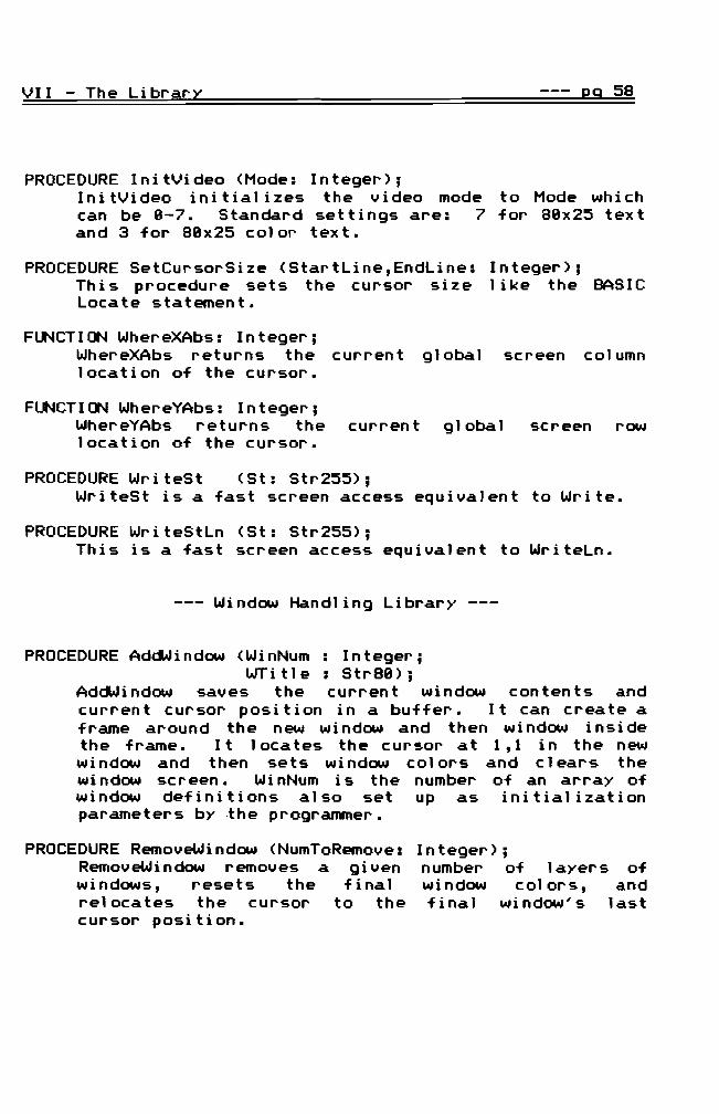
VII - The LibrQr~ 2Q 58
PROCEDURE InitVideo (Mode Integer) I n i tV ideo i nit i ali z es the video mode to Mode wh i c h can be 8-7 Standard settings are 7 for 88x25 text and 3 for 88x25 colo~ text
PROCEDURE SetCu~sorSize (StartLineEndLine This procedure sets the cursor size Locate statement
Integer) 1 ike the BASIC
FUNCTION WhereXAbs Integer WhereXAbs returns the location of the cursor
current global screen column
FUNCTION WhereYAbs Integer WhereYAbs returns the current global screen row location of the cursor
PROCEDURE WriteSt (St Str255) WriteSt is a fast screen access equivalent to Write
PROCEDURE WriteStLn (St Str255) This is a fast screen access equivalent to WriteLn
--- Window Handling Library --shy
PROCEDURE AddWindow (WinNum Integer WTitle Str88)
AddWindow saves the current window contents and current cursor position in a buffer It can create a frame around the new wi ndow and then wi ndow i nsi de the frame It 1oca tes the cursor at 11 in the new wi ndow and then sets wi ndow colors and clears the wi ndow screen Wi nNum is the number of an array of window definitions also set up as initialization parameters by the programmer
PROCEDURE RemoveWindow (NumToRemove Integer) RemoveWindow removes a given number of layers of windows resets the final wi ndow colors and relocates the cursor to the final wi ndow s last cursor position
--- 29 59VI I The Librar~
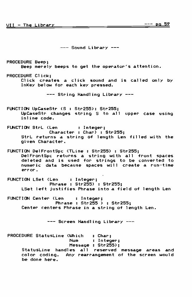
--- Sound Library --shy
PROCEDURE Beep Beep merely beeps to get the operators attention
PROCEDURE Click Click creates a click sound and is called only by InKey below for each key pressed
--- String Handling Library
FUNCTION UpCaseStr (S Str255) Str255 UpCaseStr changes string S to all upper case using in1ine code
FUNCTION StrL (Len Integer Character Char) Str255
StrL returns a str i ng of 1ength Len fill ed wi th the given Character
FUNCTION De1FrontSpc (TLine Str255) Str255 Del FrontSpc returns a string wi th all front spaces del eted and is used for strings to be converted to numer i c data because spaces wi 11 create a run-t ime error
FUNCTION LSet (Len Integer Phrase Str255) Str255
LSet left justifies Phrase into a field of length Len
FUNCTION Center (Len Integer Phrase Str255 ) Str255
Center centers Phrase in a string of length Len
--- Screen Handling Library
PROCEDURE StatusLine (Which Char Num Integer Message Str255)
StatusLine handles all reserved message areas and color coding Any rearrangement of the screen would be done here
VII - The Librar~ J9 69
PROCEDURE ErrMessage (VAR err Boolean Message Str255)
ErrMessage calls Beep calls StatusLine (2 9Message+ - KEY TO CClrrINUE) calls InKey to create a pause and allow for an Esc and returns the previous contents of line 2
PROCEDURE ManualWindow This procedure is called any time an Fl is pressed It di sp 1ays the manual ina pop-on wi ndow and allows paging through the on-line manual
PROCEDURE CommandLine (VAR Command Char CSet CharSet Message Str169)
ComrnandLi ne call s Col orCodeLi ne to di sp 1ay a colorshycoded commandline message on line 24 It then calls CharInput to input a char from CSet and sends Command character back to be used in a case to determine the next mode of operation
--- Input Library -- shy
PROCEDURE InKey (VAR Special Boolean VAR Charl Char2 Char)
InKey loops unti 1 a key is pressed If the cl ick flag is true then it also calls click when a key is pressed and returns the key that was pressed as 2 characters The Special boolean is a flag that is true if the key pressed i So a 2-code key I nKey is implemented with an MsDos call
PROCEDURE ReadStr (VAR TStr str255 LMax Integer which Char SpecialWindow Boolean
VAR BackX BackY Integer ) Absolutely all user input is entered through ReadStr in str i ng form ReadStr 1oca tes the cursor tests for actual character input and special keys and key combinations
VII - The Librar~ 29 61
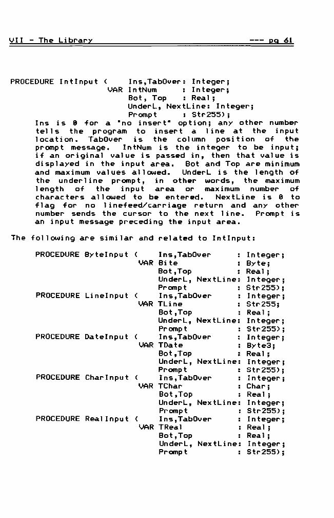
PROCEDURE Intlnput ( InsTabOver Integer VAR IntNum Integer
Bot Top Real UnderL NextLine Integer Promp t Str255)
Ins is 8 for a H no insert- option any other number tells the program to insert a line at the input location TabOver is the column position of the promp t message In tNum is the integer to be i npu t if an original value is passed in then that value is displayed in the input area Bot and Top are minimum and maximum values allowed UnderL is the length of the underl ine prompt in other words the maximum length of the input area or maximum number of characters allowed to be entered NextLine is 8 to flag for no 1 inefeedcarriage return and any other number sends the cursor to the nex t 1 i ne Promp tis an input message preceding the input area
The following are similar and related to Intlnput
PROCEDURE Bytelnput ( InsTabOver middotmiddot Integer VAR Bite middotmiddot Byte
BotTop middotmiddot Real UnderL NextLine Integer Prompt Str255)
PROCEDURE Linelnput ( InsTabOver middotmiddot Integer VAR TLine middotmiddot Str255
BotTop middotmiddot Real UnderL NextLine Integer Prompt middotmiddot Str255)
PROCEDURE Datelnput ( InsTabOver middot Integermiddot VAR TDate middotmiddot Byte3 BotTop middotmiddot Real UnderL NextLine Integer Prompt middot Str255)
PROCEDURE Charlnput ( InsTabOver middotmiddotmiddot Integer VAR TChar middotmiddot Char
BotTop middotmiddot Real UnderL NextLine Integer Prompt middotmiddot Str255)
PROCEDURE Real Input ( InsTabOver middotmiddot Integer VAR TReal middotmiddot Real
Bot Top middotmiddot Real UnderL NextLine Integer Prompt middotmiddot Str255)
eg 62VII The Library
--- Output Library -- shy
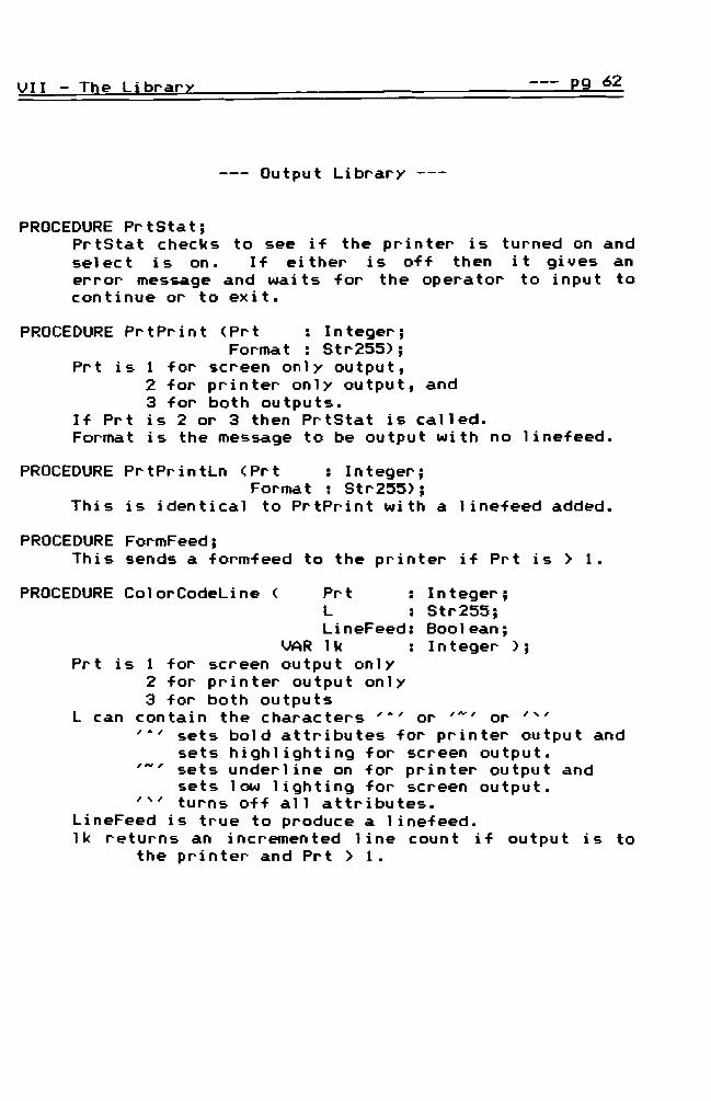
PROCEDURE PrtStat PrtStat checks to see if the printer is turned on and se1ec tis on I f e i t her i s of f then i t g i ves an error message and waits for the operator to input to continue or to exit
PROCEDURE PrtPrint ltPrt Integer Format Str255)
Prt is 1 for screen only output 2 for printer only output and 3 for both outputs
If Prt is 2 or 3 then PrtStat is called Format is the message to be output with no linefeed
PROCEDURE PrtPrintLn ltPrt Integer Format Str255)
This is identical to PrtPrint with a linefeed added
PROCEDURE FormFeed This sends a formfeed to the printer if Prt is gt 1
PROCEDURE ColorCodeLine lt Prt Integer L Str255 LineFeed Boolean
VAR lk Integer ) Prt is 1 for screen output only
2 for printer output only 3 for both outputs
L can contain the characters amp or ~ or amp sets bold attributes for printer output and
sets highlighting for screen output - sets underline on for printer output and
sets low lighting for screen output turns off all attributes
LineFeed is true to produce a linefeed lk returns an incremented line count if output is to
the printer and Prt gt 1
VII - The Library --- 29 63
--- File Handling Library --shy
FUNCTION FileLen (DF Datafile) Integer Fi 1eLen returns the number of records con tai ned in file DF It includes the number of records used and number deleted and ready for reuse
FUNCTION UsedRecs (DatF DataFile) Integer UsedRecs returns the number of used records with current data in the file DatF
PROCEDURE Oplnterrupt This procedure checks for an operator interrupt using the END key It call s CommandLi ne to ask H Do you wish to ABORT (YN)H This is used during reports
FUNCTION IndexKey (IndNum Integer RN Integer VR VariantRec)
IndexKey creates the index key for index number IndNum using the record number RN and the data record contained in VR a variant record used to pass all data records
PROCEDURE NextKey (VAR IndFile IndexFile VAR RN Integer VAR Key)
Nex tKey goes to the index f i 1e I ndFi 1e to get the record number RN of the nex t record in the index and returns the untyped Key for the next record
PROCEDURE PrevKey (VAR IndFile VAR RN VAR Key)
This is identical to Nexprevious record
IndexFile Integer
tKey above but gets the
PROCEDURE ClearKey (VAR IndFile ClearKey sets the index empty node of the index
IndexFile) pointer to the beginning
VII The Librar~ --- 99 64
PROCEDURE FindKey (VAR IndFile IndexFile VARRN Integer VAR Key)
Fi ndKey must be preceded by a Cl earKey command for IndFile It searches for the given index Key in IndFi leo It finds the first occurance of an exact match
PROCEDURE SearchKey (VAR IndFile IndexFile VARRN Integer VAR Key)
SearchKey must be preceded by a ClearKey command for I ndFi 1e I t searches for gi ven index Key in IndFi 1e For exampl e if IndFi 1e has keys of CATALYST CATAMOUNT etc and Key is CAT then the RN associated with CATALYST is returned and Key = CATALYST It finds the first occurance of the first par t of a key I f none is found then returns a global flag OK as false
PROCEDURE ManageFileSet (DoWhat Char FSet FileSetType)
DoWhat is either 0 for open or c to close files FSet is the set of numbers of the files to be operated upon Indices are automatically updated and the existence of fi les and indices are tested if a f i 1e or index does not ex i st the opera tor is asked if the file should be created
--- Miscellaneous Modules --shy
FUNCTION Yes (Ins TabOver NextLine Integer Prompt Str255) Boolean
Yes call s Charlnput wi th character set of [Y N] and returns a boolean value of true if the character is Y
PROCEDURE ClrLine Cl rLi ne clears the curren t 1 i ne where the cursor is located
PROCEDURE IntDate (VAR IDate Byte3) IndDate returns the system date in three bytes of information (yearmonthday)
VI I The Librar --- P9 65
PROCEDURE IntTime (VAR ITime Byte3) IntTime returns the system time in three bytes
FUNCTI(JoI Date Str8 Date eturns 000000
the system indata st ing form
FUNCTI(JoI Time Str8 Time returns 000000
the system time in st ing form
All other procedures and func t ions are sel f-managi ng and
wi 11 not be call ed by the appl ication programmer They
are the kernel of the system and are call ed on 1y by the
the program itself
--=== VI I I TESTING ===-shy
Testing of the 4GL must be extensive because it is the
basis of many applications To prevent compounding errors
separate testing stages are as follows
Stage 1 --- Fi 1e managemen tis tested as a separate
module to guarantee that all data is saved retrieved and
deleted properly
Stage 2 --- The menuing system and screen handling are
tested with stubbed calls to the file management routines
This includes testing the windowing system I t must be
verifi ed that all screens retain their consistency
according to the design described earlier
Stage 3 Input routines are tested separately
before integrating them into the Data Entry system The
major features to be tested include --shy
1 - the error handling for invalid entry of data --shyalphanumeric data entered into numeric fields numeric data outside of the minimum and maximum
limits characters not allowed in the field
2 - the handl ing of the decimal point in real data fields
3 - the cursor location especially in string input using both insert and over type modes
4 - the use and clarity of error messages
VIII - Testing 129 67
5 - the p~ope~ ~etu~n of the input to the calling ~outine
6 - the detection of special key combinations
The fi~st 3 stages can be tested simultaneously befo~e
me~ging them togethe~
Stage 4 --- Testing the me~ged modules with an actual
application while at temp t i ng addi tions updates and
del et ions of eve~y type must be comp 1eted befo~e test i ng
the ~epo~t gene~ation modules
Stage 5 Repo~t modules a~e now tested with
standa~d sc~een layouts and then with va~ious columna~
layouts Reco~d coun ts col umna~ totals and pagi ng a~e
tested extensively
Stage 6 The final testing is a ~elational
accounting application me~ged with invento~y pu~chase
o~de~s and point of sale invoicing
--=== IX SUMMARY ===-shy
The anal ysi sand desi gn p esen ted he e is now eady
fo anothe mo e detailed stage of design and then coding
The 4GL is bullbullbullbull not a substitute fo good analysis
6design and p oject managementmiddot The majo coding task has
been completed fo the application develope howeve a
tho ough analysis and design of the database iteself is the
top p io ity befo e using the 4GL It will be only as good
as the database design itself The 4GL has simplified the
majo functions that have now been automated The wheel
has been invented and the si x spokes a e the foll owi ng
management outines
1 - Menus and commandlines
2 - Sc een management
3 - Data ent y management
4 - Data sea ch management
5 - Repo t geneation
6 - File and eco d management
The 4GL now contains f om 88 - 9~ of the code needed fo a
elational database appl ication Wi th the modu 1a desi gn
p esented he ein the application can be expanded to
IX - Summar-i --- E9 69
include mor-e functions by (1) specific code added by the
application developer- or- (2) by additional modules or
expanded cur-r-ent modules by the 4GL developer These can
both be done wi thout disturbing the structure of the data
files themselves Therefore the primary goal of
maintenance efficiency has been maintained The secondary
goal of consistent user interface has also been maintained
wi th the above management routines Any addi tional
managemen t capabi 1 it i es wi 11 sti 11 be implemented through
the ex i st i ng struc ture for screen management data entry
management etc
The accep tance of 4GLs has grown rap i dl y wi th i n the
past few years It is however only the beginning Even
mor-e advancements must be developed to keep up wi th the
never--endi ng spec ia1 i zed needs of both today and tomorrow
Database management has led the way but a similar approach
is also needed for real-time systems and many other areas
The quest for efficient well-engineered methods still goes
on There has never been a program that is totally
finished There is always another need that it might
fulfill thus one revision after another Herei n is on 1y
the beginning of a new 4GL adventure
--=== BIBLIOGRAPHY ===-shy
1Turbo GhostWriter Taking the Time Out of Turbo Pascal This Months MENU Vol 1 No2 August 1987 pp 4
2paul Winsberg CASE Getting the Big Picture Database Programming amp Design March 1988 pp 54
3Jan Snyders The CASE of the Artful Dodgers Infosystems March 1988 pp 28
4The Reality of the Promise InfoSystems November 1986 pp 32
5 Kent Lawson Thinking About 4GLs Information Center January 1988 pp 28
6 brochures ASCII (Automated Software Concepts International Inc) received January 1988
7pascal Comdex Show 128
amounts 5 No6
GhostWriter Dai 1y Vol
to N
instant ovember 2 1987 pp
software
8 James Infosystems
R Hughes Moving Out October 1986 pp 76
of the Middle Ages
AN ABSTRACT OF THE THESIS OF
Karen I Craft for the Master of Science Degree
in Mathematics presented on March 1988
The Analysis and Design of a
Fourth Generation Language
The enclosed thesis contains a study of the first
three phases of the software engineering process as applied
to the project of creating a fourth generation language
(4GL) Initially the 4GL is defined Three levels of
users are also defined - the software engineer who creates
the 4GL the application developer who uses the language to
develop a specific application program and the final endshy
user who operates the application program created with the
4GL Incl uded are schematic diagrams to show the logic
flow of the language Sample screens are also included to
show the results of using the language for an application
The fourth generation language automates the code writing
process wi th modul es to handl e menu systems data entry
screen handling keyboard handling validity testing error
handling data access and searches report generation
printer control fi le and index management and internal
data management of buffers pointers and system functions
463000 DP OCT 21 e~
oJdd
--=== CONTENTS ===-shy
I - Introduction 1
II - Analysis 18
III - Design 18
IV Screen Design 29
v Developer Interface 41
VI - Code Design 48
VII - The Library 57
VIII - Testing 66
IX - Summary 68
Bibliography 78
--=== TABLE OT FIGURES ===-shy
FIGURE 1 - Main Menu Screen bullbullbullbullbull 30
FIGURE 2 - IO Screen Format bullbullbullbullbullbullbullbullbullbull 32
FIGURE 3 - Sample Entry Screen bullbullbullbullbullbullbullbullbullbull 33
FIGURE 4 - Sample Coding Menu Screen bullbullbullbullbull 34
FIGURE 5 - Sample Code Screen bullbullbullbullbullbullbull 35
FIGURE 6 - Application Specific Help Screen bullbullbullbullbullbull 36
FIGURE 7 - 4GL General Use Help Screen bullbullbullbull 36
FIGURE 8 - Data Search Menu Screen bull bull bull bull bull bull bull 37
FIGURE 9 - Sample Data Search Screen bullbullbullbullbullbull 38
FIGURE 10- Sample Report Menu Screen bullbullbullbullbullbullbullbullbullbull 39
FIGURE 11- Sample Report Format bullbullbullbullbullbullbullbullbull 40
FIGURE 12- Sample Report Format bullbullbullbullbullbullbullbullbullbullbull 46
FIGURE 13- System Structure Diagram bullbullbullbullbull 51
FIGURE 14- System Structure Diagram (continued) bullbullbullbull 52
FIGURE 15- System Structure Diagram (continued) bullbull 53
---=== I INTRODUCTION ===-shy
Overview --- This document contains a study of the
first three critical phases of the software engineering
process as it is app 1 i ed to the proj ec t of crea t i ng a
fourth generation language Ini tiall y it is necessary to
provide some background information which defines the terms
so-f tl4lt3re engineer i ng CASE ( Comp u t er Aided Sof tware
Engineering) and 4~ (Fourth Generation Language)
Understanding these terms will aid in better understanding
the goals of the project
Background Information --- Within the past few years
the ever-changi ng mi cro-compu ter sof tware market has
presen ted many new probl ems to sol ve I n the wor 1d of
value-added computer retailers (VARS) specific Rtarget
markets R have become the emphasis such as medical dental
retai 1er inventory accounts receivabl e or general 1edger
applications to name a few Off-the-shelf software is too
general for these spec ia1 i zed fields therefore custom
sof tware becomes a necessity Wi th the recent flood of
these market needs the software engineer is forced to
develop more eff i c i en t methods to produce the vol ume of
Q9 2I Introduction
applications needed Tom Adams team 1eader at ASCI I
(Automated Software Concepts International Inc) and the
designer of GhostWri ter describes the changes required in
the programming approach at ASCII middotWe had to find a
competitive - and affordable - way to do custom software
We decided to develop a package that automated the code
1writing process H Custom programmers find it necessary
to increase productivi ty and coding efficiency to
standardize their applications for maintenance efficiency
and st ill retain versatility Continuity from one
appl ication to another keeps the maintenance and training
effort to a minimum
Software Engineering --shy
Software engineering is not just a matter of wr it i ng code bull bull bull The sof tware engi neer i ng li-Fe cycle involves a more or less standard sequence of phases At the outset of a software project a set of requirements are gathered describing the objectives that the software must satisfy Next is an analysis of the requirements exposing important patterns and structures These are called the design specifications
At th i s poi nt sof tware desi gn begi ns Usually a schematic design phase precedes detailed design Upon completion of design code is wri tten --- this is the implementation phase -shy- followed by testing and l11dintenance
I - I~duction --- 29 3
Sof tware engi neer i ng therefore i nvol ves the foll owi ng
phases in the life cycle --shy
1 - Requirements - gathering the objectives 2 - Analysis - exposing patterns and structures 3 - Design - schematic and then detailed design 4 - Implementation- actual coding 5 - Testing - verifying correctness 6 - Maintenance - correcting updating revising
Advances in technology and techniques to improve the process have not kept up wi th the demand for new software or perhaps programmers have been too busy to 1earn them Whatever the cause many programmers have apparently decided to skip designing software in favor of just getting the job done R I t can always be fixed later R seems to be the attitude of the day
Programming is costl y enough when it is done correctly this haphazard rush to completion only adds to the costs both in maintaining the software a~ in producing truly useful applications
In a software engineering project the greatest effort is expended in the later phases of the life cycle Coding testing and maintenance take far more time than analysis and schematic design
In contrast decisions made early in the life cycle have the greatest impact on the quality and maintainability of the resulting software Studies have shown for example that errors detected during [the] requirements [phase] are correc ted in far 1ess time than errors detec ted during implementation or maintenance
I n other words the 1east effor tis i nvesied in the most important phases of the life cycle
I - Introduction --- 29 4
CASE --- A CASE produc tis any compu ter tool that
assists any phase of the software engineering process The
defini tion is qui te 1 iberal due to the fact that software
engineering itself is a broad activity -Any computer tool
that assists in the process can legitimately claim the CASE
label 2 MCASE tools perform analysis and design code
generation testing and maintenance Few i f an y do all
these things however- 3
CASE can partially automate the coding and testing
phases This is the goal of application builders and code
generation products CASE will also promote standardshy
ization and support better and more accessible
documentation resulting in lower maintenance costs In
this way CASE will in principle redirect resources to the
cr it i ca 1 phases of requ i remen ts anal ysi s and schema tic
2designshy
Through extensive user surveys (published in CanputerAided So-ftAlt3re Engineering CASpound) BTR [Business Technology Research of Wellesley Hills MAl determined that most users have been emp 1oyi ng CASE tool s for on 1y the past 18 to 24 months [as of March 1988l
CASE tools break down into two segments design automation and programming Programming tool s are primari 1y avai labl e on IBM mainframes at prices in excess of $100OOO according to Bayer [David Bayer an industry analyst with Montgomery Securities San Francisco CAl The
I - Introduction --- eg 5
trend however is to less expensive products that can run on micro and minicomputer workstation platforms He expects more sophisticate2 programming tools to appear this year [1988]
The proj ec t inc 1uded herei n is fo11 owi ng the trend toward
the micro market
The CASE definition includes two distinct
technologies Front-end or upper-cd-se tools include the
ana1ysi sand desi gn ai ds B3ck-end or lower Cd-se tools
inc1 ude app1 ication generators Th i s p r oj ec t centers
around the back-end or lower case tools which are also
labeled 4GLs or Fourth Generation Languages
4GLs -These application generators assist the
later phases of the [software engineering] life cycle from
detai 1ed design through coding testing and maintenance
They focus on process format and documen ta t i on
2disciplines not information or project managementshy
A 4GL is ac tua 11 y a type of CASE bu tis more easi 1y
thought of as a subset of the CASE technology and also as
the paren t of the CASE In its broadest sense it is the
the back-end or lower CASE tool mentioned above
As a response to many new needs four th genera t i on
languages (4GLs) are becoming more prevalent and are
quickly replacing third generation languages (3GLs) such as
I - Introduction --- Q9 6
BASIC PASCAL COBOL FORTRAN etc A 3GL requ i res the
application programmer to specifically use the language to
tel I the compu ter how to do every detai 1 of each task
Using a 4GL the programmer need only tell the 4GL program
what to do This is due to the fact that a 4GL is an
organized collection of pre-written code which contains
abou t 90 of all s tandard managemen t code needed f or all
applications Just as an operating system is a collection
of standard 1ow-I evel menial tasks that all users need
such as device management character manipulation screen
management etc the 4GL contains a higher 1evel
collection of management macrosmiddot that automate data fi Ie
record fiel d screen and report management tasks The
app 1 i ca t i on programmer no longer needs to II re-i nven t the
wheel II All programs developed wi th the 4GL then become
standardized in these tasks and all standard or common
tasks are handl ed the same from one app 1 i ca t i on to the
next A 4GL does the same thing for application programs
that the operating system does for hardware onl y at a
higher level The operating system standardizes the
interface between the programmer operator and hardware
devices and the 4GL standardizes the interface between the
programmer operator and the appl ication A truel y
I - Introduction --- --- pound9 7
efficient 4GL will automate as many standard or normal
tasks as possi bl e All that is left for the appl ication
programmer to do is to add the non-standard tasks specific
to the application
4GLs have al so been descr ibed as Ha con t i nued
ev 0 1uti on of languages H4 Ha specialized language that has
been designed to do a specific function H4 as being Hable
to do a task with roughly one-tenth of the code needed in a
3GL H 4 bull HWi th 4GLs the prec i se ins truc t ions have been
automated The language has been demystified 4GLs employ
a dialogue between user and computer interacting to solve
the users probl em The focus is on the task not on the
5computer H
Many 1evel s of 4GLs ex i st from simp 1er 4GLs wh i ch
allow an end-user to create a simpl e database to powerful
system-house 4GLS used by software engineers The
difference between the two is the degree of flexibility and
of the de ta i 1 allowed i nits use The simpl e 4GLs allow
for only very basic standard functions while the powerful
4GLs allow the versa ti 1 i ty of adding the unusua1
nonstandard func t ions when needed usi ng the host 1anguage
and the extended DmacroH language of the 4GL itself This
study considers the later the powerful system-house 4GL
I - Introduction --- --- 29 8
ASCII the producers of GhostWriter define their
product as (1) an automated code writing process (2) an
application generator (3) an ap p I i ca t i on development
4system and (4) a CASE (Computer Aided Software
5Engineering) product for program development The
engineering approach contained herein echoes these four
def i nit ions and consi ders the 4GL as an ex tensi on of the
Pascal language with the creation of 8macro 8 procedures and
functions for system-house use to create rela ti onal
database management applications
Summary In summary this document contains the
study of the first three cri tical phases of the software
engineering process (the requirements analysis and design
phases) for a four th generat i on language Br i ef I y th i s
involves a subset of the CASE technology called the
appl ication generator technology (al so call ed back-end or
lower CASE) It can also be described as an automatic code
generator wi th screenreport creat i on dictionary
definitions data base management procedural language and
functional integration as described in 8The James Martin
Productivity Series82
The creation of a fourth generation language (4GL)
I - Introduction --- ~ 9
itself requires quite an involved programming project The
ASCII programming team spent three-and-a-half years work on
1their GhostWriter written in Turbo Pascal This document
analyzes the type of product produced by this company
--=== I I ANALYSIS ===-shy
A high-level analysis at this point involves sever-al
d i r- ec t i on s bull The fir-st step is to define the user-s and
their- r-espective needs
The User- --- Defining the needs or- r-equir-ements of a
softwar-e pr-oject also initially r-equir-es defining the
user- In or-der- to avoi d any confusi on thr-ee ter-ms ar-e
used consistently within this document -- shy
(1) The softwar-e enQineer- who cr-eates the 4GL (2) The application developer- who uses the 4GL (3) The clientend-user- or- oper-ator- who uses
the application cr-eated with the 4GL
In this situation the application developer- (also known as
a system developer-) is the user- of the 4GL however- while
using the 4GL this developer- pr-oduces appl ications for- a
var-iety of clients or- end-user-s This r-equir-es that the
4GL be wr- it ten in such a manner- as to a 11 ow for- many
di ffer-en t var- ia t ions in database app 1 i ca t ions Ther-efor-e
analyzing the needs of the application developer- also
involves analyzing the needs of as many client applications
as possible The application developer- becomes the Dmiddleshy
manU for- the client the final application end-user- Thus
two 1evel s of ana 1ysi s ar-e consi der-ed the needs of the
II - Anallsis 29 11
application develope~ and the needs of the develope~~s
clients
James Hughes explains a standa~d app~oach to the
analysis p~ocess --- At p~oject initiation a p~oject team
- consisting of systems analysts and use~s assigned full
time to the team - must define the p~elimina~y requirements
of the system
Traditionally at this point analysts would interview
dozens of users to determine requirements This often
produces a long list of wants and needs that are difficult
to analyze and use for system development
A better approach is to involve a few experienced
users in the definition of preliminary requirements and
major system externals - such as menus data-entry sc~eens
on-line query displays and reports These system externals
should then be incorporated into a horizontal prototype
middotUsers can review and rank the functions in the
horizontal prototype to determine which functions should be
8 au tomated
Software En9inee~ and Application Developer Needs --shy
The software engineer (the 4GL developer) and appl ication
developer (use~ of the 4GL) have much in common They are
eg 12II Anal lsi s
both developers for a cl ient The software engineer
creates general applications for the application developer
and the application developer creates specific applications
for the clientend-user As mentioned in the introduction
several quality requirements include increased productshy
ivi ty code efficiency maintenance efficiency standardshy
ized appl ications and versati 1 i ty Further clarification
is now needed
Increased productivity involves the production of an
application in less time than with previous methods This
is easily measureable by keeping time logs on all projects
however one must remember that not all projects are
created equal
Maintenance includes updating the system for changing
needs correcting errors and adding new capabi 1 i ties In
most organizations it is estimated that 78 of the
programming is dedicated to maintaining existing systems
Wi th 4GLs 78 of the time is spen t on or i gi na 1 codi ng and
38 on mai n tenance 4 A rat i 0 of 88 - 28 is the mi n imum
acceptable goal of this project with the ultimate goal of a
95 - 5 ra t i o The appl ication developer is required to
provide parameters to the 4GL to define the data file
II - Anal~sis --- 29 13
structure entry screens and report formats In other
words the majority of the time for using the 4GL is spent
in designing the appl ication database as is necessary in
any application however little additional time is needed
beyond that stage
Efficiency involves three major areas of concern
speed memory and maintenance efficient code Speed
eFficiency can be measured wi th timing tests The 4GL
developer must consider disk access time when using
overlays and managing data files Both the software
engi neer and the app 1 i ca t i on developer have access to the
use of in 1 i ne and ex terna 1 code to speed up processi ng
H~ory efFiciency can also be implemented using inline and
external code Due to the fact that the constraints of the
proj ec t inc 1ude use of PCXT equ i pmen t it is necessary to
keep the code as compact as possible The 4GL developer
can compare the memory required by one algorithm over
another in order to determine the memory efficiency
~intenance eFFiciency is included here as the top priority
requirement It is not a truely measurable feature
However all desi gn for the software engineer and
application developer must have an under 1yi ng purpose of
29 14II - Anal~sis shy
being easily updateable as new needs surface This becomes
a Y gray area- An elaborate algorithm may be quite
efficient time- and memory-wise but too difficult to
maintain because of a lack of readability Readability is
based upon the opinion of the programmers and dependant
upon their expertise Readability and maintenance have top
priority over speed and memory
Standardi zing app 1 i ca t ions is impor tan tin two maj or
ways From the programming and maintenance point of view
standardized al gori thms prevent reinventing the wheel and
save much development time From the appl ication
developers point of view this is the major purpose fo
usi ng the 4GL The app 1 i ca t i on developer no longer needs
to be concerned wi th how the app 1 i ca t i on handl es menus
input keyboard handling validity testing and error
handling output and printer control screen functions
color coding and windowing search routines buffers
pointers system functions or even the processing of data
i ndi ces and f i 1e managemen t bull These are tota 11 yin the
control of the 4GL The application developer then is
concerned wi th whtilt the system must do for the special
application and not how it does it
II - Ana 1~s i s 29 15
Versatility is a quality that can really only be
measured wi th time Due to the vast range of specific
application requirements of clientend-users it is
impossible to foresee and allow for all possible features
that might be needed by the appl ication developer After
the major design requirements are defined a further
requirement is to allow for direct appl ication programmer
code wi thin the program to add the non-standard features
Standard code is code that is protected and not allowed to
be changed by the application programmer The requirement
of versatility is provided for with code files accessible
to the application developer that contain stubbed
procedures in which any unforeseen specific application
requirements are coded by the application programmer
Standard Pascal commands and an extended language set of
4GL macros ltdescribed in more detai 1 later) are avai lable
to the application programmer as the specific code is
added The standard code files created by the 4GL
developer are designed to handl e 89 - 99 of all
application needs These include automatic handling of the
functions listed in the middotStandardizing Appl icationsmiddot
paragraph above Additional code added by the application
developer is typically 1-5 of the total
II - Analysis --- --- Po 16
ClientEnd-User Needs --- Quite often the clientendshy
user is a novice wi th respect to computer operation All
design is directed to the needs of the new computer user
As mentioned earlier maintenance is the top priorty of the
entire project but consistent user-interface is the second
priority Every move required from the operator is to be
thoroughly prompted In more specific terms this first of
all requires a stdnddrd screen Id)oUt in order to assure
the operator that all prompts will be consistently seen in
the same format throughou t the en tire program opera t i on
Color coding aids in prompting the user also Help screens
are avai lable at all times Ddtd input is prompted at the
field level with data type data limitations and field
descriptions All data is checked for fIlt3liditv and any
required or coded fields are tested before saving the
record to the database S~rches of the database allow for
mul tiple searches for any limitations on any or all fields
available in the file The first phase of development
allows for searches of concurren t search cr iter ia however
the second phase allows for OR NOT XOR and wi 1d card
searches Report Forl11dts allow for col umnar formats page
numbering column totals and counters Printer
attributes such as bold and underline can be embedded in
II - Analysis --- --- P9 17
report formats User-entered subtitles are also allowed
Summary I n summar y the fun c t i on s t ha t wi 11 be
automated include
1 - a menu system 2 - data-entrydisplay screen functions
(IO screens) color coding windowing
3 - data entry keyboard handling validity testing error handl i ng
4 - data access (searches) 5 - report generation (output)
printer control 6 - file management
indices saving deleting reading data file
7 - internal data management buffers pointers system functions processing of data
--=== I I I DESIGN ===-shy
The top 1evel design concen tra tes upon the usershy
interface The lower 1evel of design concentrates upon
the mechanics and maintenance aspects This chapter will
discuss the top level designing phase in terms of general
requirements and of the functions to be automated
Phased Development --- Development of this project
is designed for two major phases The first phase uses
Turbo Pascal 3x BCD with the top priority features The
second phase uses Turbo Pascal 4 and adds the more
detailed features described in the following
System Requirements --- Design begins with the
declaration of the constraints This project is to be
impl emented on IBM PCXTATs or compatibl es (XTATs are
preferrable) with DOS 31 or higher and 328K of RAM A
hard drive is recommended and mono CGA or EGA monitors
are supported The application developer is required to
use Turbo Pascal 3x in the first phase of development and
as soon as version 4 is shipped the second phase will use
it as its base
III - Design IUl 19
Initialization --- A parameter passed in with the
call to execute the program declares to the program where
the data files are located ie the drive and subdirectory
specifications This allows the operator to keep sets of
files within separate subdirectories Once loaded the
ini tial ization of the appl ication program created by the
4GL includes an option for immediate update of fi les and
the ini tial ization of the date Exit from the program is
possible even from this point A personalized logo
screen desi gned by the appl ication developer then
appears to declare the program name and any copyrights and
dates needed Pressing a key continues into the main menu
screen
Menus The main menu for the entire appl ication
created by the 4GL includes a 1 ist of installed database
applications For example a simple menu may include --shy
e = Codes 1 = Chart of Accounts 2 = T~ansactions
3 = Audi t Trai 1
Each menu sel ected resul ts in the use of the same screen
1ayou t descr i bed in more detai 1 1a ter When a menu i tern
is sel ec ted the appropr ia te f i 1es are opened the IO
III - Design 29 20
screen is created and the file and field definitions are
initialized
Command Line Once within a menu selection a
commandline appears at the bottom of the screen Two
forms are used The first allows adding and updating of
records and the second allows only reading of data ---
MenUj AddUpdatej FindDataCINtj RtpOltj PgUpj PgOn ---) enuj FindDataCINtj Reportj PgUpj PgDn ---)
Phase 2 includes security password options which allow for
readwri te access or read only access therefore
determining which commandline the end-user will see
IO Screens --- Data entry and display (for browsing
through a search buffer) screens are the same Standard
IO screens contain the following
1 - the menu title 2 - the current mode of operation 3 - a message area for errors and how to exit 4 - a data entry area 5 - a comrnandline area 6 - a field-level prompt area 7 - an input prompt for data entry limitations 8 - a status line including --- the number records in the curren t f i 1es the number of records in the search buffer the record number of the record curren t 1y bei ng en tered or viewed
II I - Desi 9n --- 29 21
Help Screens --- Help screens are constantly
available by pressing the F1 key Phase 1 help screens
inc 1ude user-spec i f i c i nforma t i on such as accoun t i ng
aids and a user manual displayed sequentially in a
circular list as the space bar is pressed Phase 2
screens allow for going to specific pages in the on-screen
manual for scrolling forward and backward sequentially as
desired and allows for context-sensitive help The
standard user manual is pre-installed however this manual
is accessible to the application developer for editing
Data Entry is standardized with IO screens defined
by the application developer All data is entered within
these screens and also displayed within them when in
browse mode to page through a set of records in a search
Data entry is also dependant upon file definitions defined
by the application developer using parameter tables File
sizes access codes indexing and field definitions are
contained in these tables Data entry in a field uses the
field definition to determine data type field length
validity tests and its location within the record Each
field has field-level prompts displayed as the field is
entered by the operator
II I - Desi gn --- --- eg 22
Phase 1 includes data types of string integer BCD
real byte date and character Automatic sequential
f i el ds (such as sequen t ia1 i nvoi ce number i ng) and defau 1 t
fields are supported A key click option is available for
keys pressed A lookup fac i 1 i ty is bu i 1 t-i n for coded
data fields as explained in the next section on the
middotCoding Systemmiddot Validity tests are performed at the
field level Coded fields are allowed which require entry
of only preinstalled codes Numeric data is tested for
minimum and maximum limits String data entry is not
allowed beyond its maximum length limit Date entries are
also tested for val id dates When an entry is executed
usi ng the FlO key the record is tested for the ex i stence
of required fields If the record is acceptible it is
recorded and any updates to related files are also updated
at that time such as updates to chart of account totals
when a transaction is entered
Phase 2 adds data types for telephone numbers zip
codes social security numbers time and short dates
(mmdd)
II I - Design 29 23
Coding System --shy Due to the fact that it is storage
efficient to use codes for some data fiel ds a standard
for all applications is a built-in coding system Menu 8
is reserved for Codes This menu selection allows the
initialization of a coding library which contains lists of
)i available codes used in the data entry of the entire
t ~ program All coded fiel ds used throughout the program
reference th i s code library to test the va I i di ty of the
data entry for that field Therefore all codes must be
~ i entered in the coding library before they will be accepted
as valid data in the coded data fields No duplicates are
( allowed An example would be codes for source documents
in a transaction such as middotCK for check or IN for an
invoice These codes are indexed and quickly accessible
at any time during data entry ltadding or updating) by
pressing the F2 key A pop-on window lists the installed
I~ codes and their descriptions in alphabetical order and in
a circular I ist for paging through The operator then
returns to the data entry from whence he came Once a
code is used as a reference in a coded data field that is
saved to a file the code is flagged and will not be
allowed to be deleted to guarantee that it can be
referenced by the coded field later
Design --- --- pg 24
Data Searches --- A data search menu includes a
numbered 1 ist of all the fields in the records involved
wi th the curren t menu selection The end-user has the
op t ion to se1ec t an~ or all numbers of the fiel ds for
which he wishes to request concurrent special criteria (a
logical AND search) After selecting the proper fields
the end-user is prompted for the special search cri teria
Str i ng searches are case i ndependen t and allow for two
search type options -Begin-End B searches locate data
matching and between a user-input beginning string to an
ending string Data is matched from the beginning of the
data fiel d I tallows for a search such as all names
beg inn i n g wit h ~ a ~ to m -Within- searches locate all
data fields which contain the user-input string wi thin
them Numer i c and date fields allow the user to input
minimum and maximum limits on the search
Searches involving an indexed field will be
imp 1emen ted usi ng B-tree index i ng and other searches wi 11
be sequentially implemented Data search records are saved
in a circular linked list called a search buffer The
search buffer can be used for browsing through the data on
the screen (pagi ng to the prev i ous or nex t record) or to
print out numerous reports Once the search has been
II I - Desi gn 29 25
used the search buffer can be cleared
To see what search cri teria have been used for the
current search buffer the operator can enter D for data
at the commandline A pop-on window will display the list
of cr iter ia used for the search The coun t of records
con tai ned in the curren t search buffer wi 11 be di sp 1ayed
at the bottom of the screen
Phase 2 will add the OR XOR NOT IF-THEN-ELSE and
wi 1dcard searches and al so wi 11 allow for ascending or
descending sorts according to any chosen combination of
fields Search and replace features will be added in this
phase An operator option is available to search for caseshy
sensitive data Ad hoc searches are allowed in this phase
and commonly used searches are saved as standard -macrosmiddot
Data Reports --- Report formats are initialized by
the application developer In phase 1 these will be
imp 1emen ted usi ng tex t f i 1es These forma ts wi 11 inc 1ude
field locations and field numbers Special printer
options such as bold underlining and compressed print
wi 11 be imbedded wi th i n the formats When request i ng a
repor t the end-user is requested to in it ia1 i ze a search
if none exists A numbered list of installed reports is
III - Design 29 26
displayed in menu fashion When the operator selects the
desired report he may opt to have the report format
displayed before continuing This allows the operator to
be sure he has the proper report Counters paging
col umn total s and numeric grouping (by groups of 5 for
example) are available directly through the formats
created by the application developer To implement
control breaks other than numeric grouping the
application developer adds specific code The page length
is set in the repor t format and is the key that
au toma t i ca11 y manages pagi na t i on and the crea t i on of a
title block at the top of each report One line in the
report is required to contain fields from one common file
Phase 2 allows for a more H free form type repor tin
which fields on the same line can be contained in
different data fi 1es Phase 2 uses the 4GL i tsel f to
create the report formats and parameters and also allows a
max imum wi dth repor t of 132 charac ters A mat hema t i ca1
formula or a special logic procedure can be manually coded
by the application developer
Design 29 27
Pr inter Suppor t --- Due to the fac t that there is
little standardization for the many printers on the
market each printer requires its own set of driver codes
for special attributes such as bold underline
compressed 6 or 8 1 ines per inch ital ics and double
wide Printers are supported by a parameter file
containing these code numbers The file is created by the
application developer and allows him to install codes for
for any or all printer interfaces for which he has codes
F i 1e Managemen t --- F i 1e managemen t loll ill be
implemented with a B-tree and indexing system Parameters
wi 11 be suppl ied by the appl ication developer to define
files and their respective fields Restructuring of files
is not allowed however a transfer from one file to
another can be made A re-indexing uti 1 i ty re-indexes
files that have been corrupted It uses the file field
and index defini tions to restructure indices after
renaming the 01 d indices to have as a backup unti 1 the
process has been verified The operator then has the
option to delete the old indices
User Interface --- User interface is well-served by
II I - Design 29 28
the several requirements previousl y mentioned
standardized screens a pop-on code window a pop-on
manual or help window and constant prompting at the field
1evel bull The user wi 11 know that he is expec ted to en ter
data when the color yellow (or reverse video on monochrome
monitors) appears on the screen Even character input
will be prompted by listing all possible characters
allowed in the input Error messages must be preceded by
a beep to si gna1 the user to look ina pre-determi ned
message area At all times the user will have a message
explaining how to exit the current situation The use of
keys will be consistent throughout the application for the
operator Standard key combinations are pre-installed
however these can easi 1y be re-conf i gured by the
application developer with the simple reassignment of key
constants
--=== IV-SCREEN DESIGN ===-shy
Within the next four chapters are the more detailed
aspects of the project This chapter concentrates upon
the IO screen designs used by the data entry routines and
report browsing routines
Standardized screens --- Standardized screens are
not only a benefit to the end-user but also to both the
software engineer and the application developer End-user
interface is of utmost importance due to the fact that
the majori ty of users are novices Bei ng abl e to
consistently find error and status messages and prompts in
pre-set 1oca t ions ai ds great 1yin the opera t i on of the
application program However the major advantage for the
developers is the fac t that all screen handl i ng can be
channeled through one screen formatting module Any
desired changes in the screen layout are made in that one
module Figure 1 is an example of a main menu screen from
an application using the 4GL
IV - Screen Design --- 29 38
FIGURE 1 - Main Menu Screen
HODE = Cllllland -( HAIN HENU 1- Fl =Hanual EXIT Prbullbull = Esc
8 =CODES 1 =CHART OF ACCTS 2 = ACCOtMING 3=AUDIT TRAIL 4 =SUPPUERS 5 = CUSTIltERS 6 = ItfJENTORY 7=SALES
Stlct I from about ---)
FILES ScFILE= FO~D= Curllt= bull INPUT Int= - 7
IO Screen --- When a mai n menu item is sel ec ted
the program then uses the standard IO screen shown in
Figure 2 and described below The following list contains
the description and location of the standard items in the
screen layout and their reserved areas
Name Line Description of use
Mode 1 Di sp 1ays curren t mode chosen from the commandline menu
Command means it is wai t i ng for a command
Add or Update are data entry modes
Title 1 displays the title of the item selected from the main menu
IV - Screen Design eg 31
Name
Manual
Message
Work area
Commandline
Files
SecFile
Found
CurRN
Input
Line
1
2
4-22
24
25
25
25
25
25
Description of use
always shows how to get the pop-on manual or help screen
displays messages such as error messages that tell what is wrong and what to do about it how to exit special instructions for the current situtation
area for entry and data display
commandline menu field level prompts
number of records used in current file
number of records used in curren t secondary or re 1at i ona 1 f i 1e such as a file containing sold items related to a primary fi 1e of invoice data
number of records found in a search and contained in the current search buffer
record number of record curren t 1y displayed on screen (the actual physical location within the file)
prompt area for absolutely every operator input in these formats Byte= - Int= - Real= - Max Length= (used for strings) A C D F M R U ( examp 1e of c harac tshy
er input for commandlines)
IV - Screen Design --shy eg 32
Figure 2 - IO Screen Format
HODE =1111111111 --- title area l--- Fl =Hanual message line for errors and exits
This is the working area used for data display and entry
Line for commandline and field-level praaptsFILES=IIIII SecFILE=11111 FOUND=IIIII CurRN=11I11 IIINPUT 111111111111111111
Figure 3 below demonstrates a feature that an
application developer may use for columnar-type data
entries It exemplifies an actual entry screen as may be
def i ned by an app I i ca t i on developer for the en try of an
accounting transaction The example shows the screen
after three transactions have been entered In this
application all entries are made on the line directly
under the column headings When the transaction is saved
by pressing the Fie key a prompt line is inserted at this
location pushing the previous transactions down thus
keeping them on the screen as templates for further
entries The design of the screen within the entry area
1 i nes 4 22 is under the control of the appl ication
developer On line 24 is a field-level prompt describing
the current field at which the cursor is located
IV - Screen Design --- Q9 33
Figure 3 - Sample Entry Screen
HODE = Add - ACClHNTIN6 1- Fl = Manual Esc = Canand Line ENTIN F7 = Del i Fl1 = Save bull F2 = CODES
BIT bullbullbullbullbullbullbullbullbullbullbullbullbullbull I CREDIT bullbullbullbullbullbullbullbullbullbullbullbullbullbullbullbullbullbullbullbullbullbullbullbullbullbullbullbull I bullbullbullbullbull
Transact r-- Debit --- r-- Credit -- r SourcDate Acct Mount Acct Mount Doc Nulbtr CGRfnts
l1li7---- ------- ---- - --__ - ___88middot7middot II bullbullbullbullbullbullbullbullbullbullbullbullbullbullbullbullbullbullbullbullbullbullbullbullbullbullbullbullbullbullbullbull
881111 1111 33452 3121 33452 B6 Beginning Bank Balance 8811112 6121 2367 un 2367 CJ( 3241 Insurance Pa~t
Enter YearA10nthlDay as 87 31 5 --- zeros not nussaryFILES 2 SecFILE= FoaD= Curllf= 3 INPUT Byte= 1- 12
On the fourth line above the name of the debit or credit
is printed in the spaces when the respective account
numbers are entered and found to be val id Thi sis a
result of two lines of specific code added by the
app 1 i ca t ion developer Th i s presen ts an examp 1e of wha t
special features can be accomplished with the 4GL
Color Coding --- When the operator sees this screen
on a color mon i tor the data en try area for the mon th is
highlighted in yellow to indicate that this information is
what is to be entered Yellow sayS Hdo somethingH The
two bottom lines also verifiy what is to be entered
light cyan while the current data entry field is yellow
screen is avai lable by pressing the F2 key whi le in the
This
29 34
Ft =Manual
The mode Ft = Manual and
2 = stfPllER CREDIT CODES 4 =ItfJlMORY rATE60RY CODES 6 =SAlEIIN
CurRN= 3 bull INPUT Jot= 8shy 255FOlND=
Entry data that has already been entered is
Secfile=
Pop-on Code Screen --shy Figure 4 shows an example of
I
MODE =Add bull CODES ) Esc =exi t Code Win-ire bIr =11 for lOre I
t = SOURCE DOCIKNTS 3 =CUTOHER CREDIT TEAMS 5 =SAlE CODES 7 =INSTALLERS
Enter Code number desired ---) bullbullbull
FllES=
I I
Col umn headi ngs are red
IV - Screen Design
screen after selecting a particular code to 1ist
status data on the bottom line are coded green Titles
are brown
Add or Update mode
a coding menu screen and Figure S shows an example of the
Figure 4 - Sample Coding Menu Screen
-- ------ ------------------------------- -
IV - Screen Design --- 29 35
After selecting the code listing desired (1 for example)
a screen similar to Figure 5 is seen
Figure 5 Sample Code Screen
MODE = Add -l ACCOlNTIN6 1- Fl = Hanual CODES] Esc = xi t Code WindcMijC blr = for _or _
r CODE DElETEDESCRIPTl~ 1 SOURCE DOCIl1ENTS N 1 CH Cash Transaction N 1 CK Chck Transaction N I IN Invoic Y 1 IT Intlfst N
bull FILES= Scfi IF F~D= Cur~ 3 bull IIftT Int= 1- 255
ManualHe1 2 Screens The on-line manual is
available at any time by pressing the F1 key Below is an
exampl e of an appl ication specific hel p screen and of a
4GL general help screen
IV - Screen Design --- 29 36
Figure 6 Application Specific Help Screen
HODE = -[ ACCOtHTING 1- FI = Hanual Esc = exit Hanual Windlllj space bar = page for ore
F[ tWIW I II bull ACCOIlflING EQQTI~ _
---- ASSETS I = r LIABILITIES -- r-- EQUITY -----increase Assets Otcreast Assets UtCrNst I IncrNse DtCrease I Increase NIM Assets I AcclII Deprec Paid I Payable Oraliting Capi tal Unexpired Insur I Unearneo FItS PrePaid Expense (Advanced Rev) ItmtE stJttARY Received Paid (tllporary proprietorship)
btcrease Equity I Increase Equit Expenses Revenues Inventory (Btgin)l Inventory (End)Purchasts Sales ContraRlVenue ContraPurchasts
(SalK RetaAl) I (Pur RaA)(SalK Discts) (Pur Disc)
Tran~ort-iR I Uncolltct Accts
Henui AddUpdate FindDataClearj Re~orti PaUDj PaOn ---) bull FILE~ 67 StctILE= FOtH)i 23 urlN i8 bull INPUT ACDFHRU
Figure 7 4GL General Use Help Screen
HOOE= -[ ACCOtHTING 1- FI = Hanual Esc = exi t Hanual Windlllj space bar = page for ore
F[ HINW I bulllin bull SPECIAL INPUT KEYS _
I fIiil IBlcSpc --- Hoves cursor to I--J ~ I Tab I NEXT input field Nlllber Keys at Otletes character L=J Top of Keyboard btfore cursorl ~LY
key used to eait WITH S or NIIILock NlttERIC fields
Ctrl ~uses a scrolling scrttn ~ Press Space Bar to continue
--- WITH TAB moves cursor I IShiftl to PREVIOUS input field I L-J I Deletes character I --- above cursor in
I Alt I text input field (DllI I--J I--J
I I
Menu AddIpdate FindDataClearj Re~ortmiddot PaUDj PQOn --) bull FILE~ 67 Stc~ILE= FOUND= 23 turAN= as bull INPUT ACDFRU
IV Screen Design 29 37
Data Searches --- From the commandline the operator
may select RF R for Find to initiate a data search Figure
8 shows an examp 1e of a data search menu for a Char t of
Accounts application Every possible field is listed and
the operator may select one or all of the fields to search
by If a string field is selected the operator has the
option to select a UBegin-End or RWithin U search as
described earlier Ifanumer i c or da t e fie 1dis
selected the operator is prompted to enter the minimum
and maximum desired in the search
Figure 8 Data Search Menu Screen
ODE = Search --I~RT OF ACCOINTS]shy Fl =Hanual EXIT Search l1tnu =Esc
II SEARCH tINU II
1= ClIIlt 2= NoDlt 3= Acc 4= Acct ~ ~ Dscript6= ~ln Sal 7= Jan Total 8= Fib Total 9amp Har Total 11= ~r lolal
11= Hay Total 12= Jun Total 13= Jan Total 14= Aug Total 1~ Sp Total 16= Oct Total 17= NOli Total 18= Otc lotal 19= IstQtTotal 21= 2nijOtlotal21= 3rdOtTotal 22= 4thQtTotal
Entr I of ittms to b searchd --- bullbull
FILES 48 ScFILE= FOlND= Curlt+= 42 INPUT 1- 22
- ------------------ -------------------- --------------------
IV - Screen Design Eg 38
Search Da ta Wi ndow --- The opera tor may request a
listing of the search criteria used to collect the current
search buffer (just in case one forgot) by pressing 8D8 in
the commandl i ne A pop-on search cr iter ia screen appears
listing all limits of the search as in Figure 9 below
Figure 9 Sample Data Search Screen
MODE = ClINnd -[CIMT OF ACCOOOS)- Fl = Hanual
bull Search Data 1bullbullbullbullbullEsc=lXiiltiifrIliCIIwiiidcMbullbullbullbullbullbullbullbullbullbull
II SEARCH JTB1 FRIJt ( =begin srch) - TO
3 =Acct NwI 2 - 4999 4 =Acct tell A - F
I I I~------------FILES Slcfile= FOlJiD= CurRN= 3 INPUT ACDFRU
IV - Screen Design 29 39
Data Reports --- A report may be initiated after a
search I f a repor tis requested and a search has not
been executed then one is autornaticall y requested from
the opera tor A search menu is then 1 isted as in Figure
19 below The operator has the option to see the report
format (Figure 11) before executing the report in order to
be sure it is the correct one Following that the
operator may opt to have the search criteria listed in the
headi ng of the repor t to have page numbers and to send
the report to the screen printer or both
Figure 19 Sample Report Menu Screen
HODE =Rtpor t -[CWIRl OF ACCOOOS)shy FI = Hanual EXIT Search Menu = Esc
III REPORT ~ III
I = Chart of Accounts 2= Account BalanctS - Yearly3 = Account Balances - 1st Quarter 4=Account Balances - 2nd Quarter5 =Account Balances - 3rd Quarter 6 =Account BalanctS - 4th Quarter7 =Account Balances - Beginning 8 = Financial Report
Enter report number --- bullbull
8FILES 48 SecFILE= FOUND= 28 CurAN= INPUT lnt= 1shy
IV - Screen Design 29 40
Figure 11 Sample Report Format
MODE = Report -(CIMT OF ACCOlNTS)- F1 =Hanual - KEY to CINTINUE
I 111111111 ]= ACCOIHT IIAlfWES - 1st lINTER =[ 11111111
Acctl Account HInt 1------------ Totals ------------1
January Flbruary Harch Balances
1st Quarter
iiiii iiiiiiiiiiiiiiiiiiiiiiii iiiiiiiiii Iitlilliii iiialiiiii iilliiiiii 11111 111111111111111111111111 1111111111 1111II1II1 1111111111 1111111111 11111 111111111111111111111111 1111111111 1111111111 1111111111 1111111111 ----- -----------------------shy ---------shy ---------shy ---------shy ---------shy11111 listed 1111111111 1111111111 1111111111 1111111111
=I Page 11111 ]=
FILES= 48 SecFILE= FOUND= 21 CurAN= bull INPUT
-== V-DEVELOPER INTERFACE ==shy
The third priority of a 4GL must be the interface
between the application developer and the 4GL itself The
discussion in this chapter involves the communication
between the 4GL and the appl ication developer in terms of
parameters which define IO screens output report formats
and the database itself ltrecords and fieldsgt The major
time spent by the appl ication developer shoul d now be in
the area of the database anal ysi sand desi gn Once the
design is establ ished the installation of the parameters
involves the following steps
1 - Parameter tables define the base appl ication for A - the file data structure B - the entry screens C - the output or report formats
2 - Specific non-standard code is added using A - the 4GL RmacroR language described later B - the Turbo Pascal language C - in 1 i ne and ex terna1 code allowed through
Turbo Pasca 1 bull
In phase 1 the implementation of the parameter tables is
through tables set up in standard text files Phase 2 uses
the 4GL itself to create these interface definition files
The structure and content is the same wi th each method
The phase 2 method allows for greater security and speed in
reading the files and initializing the file definitions
internally within the program
v Develoger Interface --- 19 42
I n i ti ali za t i on The application developer must
provide parameters for initialization of the system These
include
1 - the location of the data files 2 - The computer type (PCXTAT) 3 - video mode 4 - the filler character for entry areas 5 - the clientend-user name 6 - the program name 7 - the logo screen with copyright and date 8 - the option to have the click sound for keys 9 - a table of the main menu selections and
their related files
The menu title is used in the main menu and when a
selection is made it is used in the title area of the
en try screen The related files are automatically opened
managed and closed during the use of that menu item
IO Screen Defini tions --- Screen defini tions start
wi th the definition of the window environment This
includes
1 - The related file number 2 - The upper left corner location 3 - The lower right corner location 4 - Background color 5 - Foreground color 6 - The window frame type number 7 - The title color
v - Deyeloper Interface --- 29 43
Screen definitions include a table of the following data
per source field --shy
1 - The source file number 2 - The en try order number (3 for 3rd f i el d
entered in the input sequence) 3 - Field location on the global screen 4 - Field number within the data file 5 - Location of the lower right corner for a
windowed field (as for a multiple line c ommen t fie 1d)
The final step in defining a screen is the actual contents
of the work i ng or data en try area of the screen such as
the entry screen in Figure 3 The column headings and the
data entry area (line 8 in the example) must be created
File and Field Definitions --- The file structure of
the database is the basis of all specific data input
routines f i 1e and record management routines and
outputreport routines The file and record definitions
ar e c r ea t ed i n tab1e form ina t ex t f i 1e ca 1 1ed F i 1eshy
DefPAS The file contains the following data pertaining
to a specific file --shy
1 - File security code (readwrite read only) 2 - Record size 3 - Number of fields per record 4 - Set of indices indexing the defined file 5 - The major index for the file
v - DeveloQer Interface --- --- pg 44
It must be remembered that the 4GL does reserve menu 8 and
file 8 for the code library described earlier
File-DefPAS also contains a table of the following
data pertaining to specific fields within a file --shy
1 - Field data type 2 - Field name (used in the search menu) 3 - Field-level input prompt 4 - An upper case flag for string data (yesno) 5 - Field length internally within the record 6 - Field offset internally within the record 7 - Field minimum and maximum acceptable values 8 - Character set possible for character data
The final table included in File-DefPAS is another
table containing the definition of the indexing system --shy
1 - The source file for the index data 2 - The total number of fields used in the key 3 - The set of ordered fields to create the key 4 - The key size in bytes 5 - A duplicate key flag (yesno)
OutputReport Def i n i ti ons Output formats for
reports use the file field and index definitions entered
as parameters by the appl ication developer to create the
pr oper data forma t to pass to the repor t rou tine The
report formats are contained in a file called Rep-DefPAS
It is initialized with a table of --shy
1 - Report name 2 - Related menu selection number 3 - Report number
v - Develo2er Interface --- 29 45
The initialization table i s f 0 1 lowed by the report
formats A format is initialized with -- shy
1 - The report menu number 2 - The report number 3 - Page length of the reportdocument 4 - Body length of the reportdocument 5 - The number of records per group 6 - The line spacing between groups
Items 5 and 6 allow for example for the grouping of data
in sets of 5 lines and then double spacing between them for
readability
The actual body of the report is created in the
following manner by the appl ication developer Figure 12
gives an example of an accounting report format The first
charac ter per format 1 i ne descr i bes the use of the 1 i ne
The codes are
T - Title line (No data input into this line) D - Divider line (No data input) C - Column heading (No data input) 1 - Primary file data line F - Footer line (fields are totals or counters) P - Page number line
The symbol represents the location of a field within the
report line
v - DeveloQer Interface --- e2 46
Figure 12 Sample Report Format
ACCOIHT BALmCES - 4th QIWlTER =[ 1 T ]=D==================== C Acct Account NaIIe October Novuer DecBlber Quarter Bal C ----- ------------------------ --------- --------- --------- --------shy1 bullbullbullbullbullbullbullbullbullbullbullbullbullbullbullbull bullbullbullbull bullbullbullbull bullbull bullbullbull11 bullbullbullbullbullbullbullbullbullbull 1 F F
bullbull11 listed 11F P =[ Page 11111 ]= l1li Source Data bull Line Source Num bull Num FileSub Flds Source Field Arraymiddot---- ------- ---- - -- -- -- -- -- -- -- -- -- -- -- -shy 5 1 6 2 3 15 16 17 21 7 1 4 8151617
The lower source data part of the table above defines the
field content of each input area for the fifth and seventh
lines in the format The example defines the primary file
as the source for the fiel ds 1 isted in the source fiel d
array The fifth line for example has 6 fields which are
numbered 2 3 15 16 17 and 21 input into the format
This works much 1 ike the FORM command in Turbo Pascal 01
like the PRINT USING in BASI C Fi el d number 9 the fi rst
source field on the seventh line represents the record
coun tat the bot tom of each page of the repor t bull If the
page numbering option is selected at the time of the
repor t then the page number wi 11 be pr i n ted usi ng the
format line preceded by the HP Hbull
v - Devel02er Interface --- 29 47
Spec i f i c Code --- A standard 1ogi c for I PO (i npu t
processing output) is embedded into the system however it
is impossibl e to foresee all uses for a program (as the
many versions on the market prove) Therefore the use of
unprotec ted stubbed procedures wi thi n the 4GL system allow
for the application developer to further customize the
final application Turbo Pascal commands inline code
external code and internal 4GL middotmacrosmiddot are available for
the application developer to complete the specific code
The following chapter describes the middotmacromiddot language in
more detail and lists the major middotmacromiddot library procedures
and functions
Th i s sp ec i f iccode sh ou 1d be the on 1y par t of the
final appl ication that would possibly require maintenance
thus greatl y reducing the cost in time and manpower for
maintaining each application
--=== VI CODE DESIGN ===-shy
This chapter concentrates upon the design and
organization of the actual 4GL code modules A more
detailed level of design requires a data structure an
organization of the code files and system diagrams
4GL Data Structure --- The internal data structure of
the 4GL must be well designed in order to be parameter-
driven compact enough for PCs and as unfettered with
limitations as possible The major structures designed
within the system are --shy
1 - The use of the B-tree indexing structure 2 - The use of pointers and linked lists 3 - The direct or absolute addressing of data 4 - The allowance for subscripted arrays of
poi n t er s torec or ds f or men us f i 1es fields indices and buffers
Dynamically created definition records are used to contain
all current working data needed for the current menu item
selected
Organization of Code Files --- Due to the fact that
the Turbo Pascal version 3 edi tor can onl y handl e 64K of
code per source code f i 1e and for organ i za t i on purposes
the coding organization of the program includes the
following separate protected code files Li sted wi th the
VI - Code Design 29 49
file names are the contents of each
Type-DefPas - all type declarations and a minimum of global variables
Library Pas - a universal supporting library con tai n i ng i ndependen t modu 1es used by the entire 4GL program
FileMangPas - code for index keys file management
PointersPas - pointer management including queues double linked lists trees and buffers
Support Pas - search menu print search data window get report option data report selection module data input module record management related to
data en try ControlsPas - the 3 major controling modules
which call the supporting modules in Support above
EnterRecord FindData PrintReport
Menu-SysPas - menu system Init-FinPas - initialization and finalization
modules
Also included are two application-specific files accessible
to the application developer These are the files that
contain the stubbed interface modules for the developer
They are
SpeciallPas - UpDateAcct for accounting modules any data entry specific tests
Specia12Pas - any tests required for deletions specific report tests
VI - Code Desi~n --- R9 50
SYstem Diagrams --- The diagrams that follow present
the high-level logic and design in a form simi lar to a
Warnier-Orr diagram Figure 13 contains the most general
logic of the program Figures 14 and 15 continue with more
detail for the Record Menu Keys section in the lower right
corner of Figure 13
r-ii shyilil 111
VI - Code Design Q9 51
Figure 13 System Structure Diagram -- shy
rStt screen I Get data drive ~raleter (Mhere data Mill bt located)I Initialize 5 global variables and flags
I Initialize global ~ointers for buffers files indices menus Read defaults and file definitions
I (currtntly in sequential data file)Initial- ~ Introduction Screen ization I Collect Record Definitions
I Retain origi~l video modej set neM default video lode I Re9uest ilitdiate update yesnol Inltalize linUS file definitions buffers and printer codes
r
IClear ring buffer pointersRe-initiaTize 5 global flags
I Close open files to update disk directorr I Dispose of previous screen definition pOInters
Htnu --4 Hain IUIlU scrnn I Input neM ltAU selection
I ~en neM fi Ie set Create neM entry scrttn and saves current work windows
L
rI Initialize menu variables and pointersI
Control~ Initialize search record Loop I r
II I Initialize quit flagI I r I I I I Read Only HtftujFindlDataiClearjReportjPgUpjPgDnI I ClIIIIc1ndLi ne----- bull I I I ReadAlriteHtftulFindlDataiClearjReportjPgUpjPgDnjI I I AddIUpdateI ClIIIIc1nd Loop---- L L I Tests for mpty filH and buffers
I rPa9fYP Key (get prev record data print fields) I l Case key of ---f bull
I Pa~ Key (get next record data print fields) I bull II
IAlt PagtUp Keys (print prev sub pg Mithin record) I
I
IAlt ~agtDn Keys (print next sub pg Mithin record)
JI bull
I r tI IUpda1e (call II EnterRecord (lUIraquo 1shyI Add (call II EnterRecord (A raquo ~
IRecord Report (ca II II PrintReportgtMenu Key bull
I Clear search buffer
III Fnd data L
rI Window Mhole screen
Finali- -4 Clear screen zation I Video set to original video aode
I Be sure all pointers are nil and files closed L
e represents exclusive or or XOR logic II continued in more detail on follOMing pages
VI - Code Design 29 52
Figure 14 System Structure Diagram (continued)
r r I Cl ear rcord buHrr I IF add --f Print ntry scrttll
Elltr I I Print n~ rcord nUlbrr Rcord --I L
Initializ rcord variabls r
I SIt currtnt ntry iild location iild ltngth and oiist I St input window ii netOfd ior largr txt iilds
Entry --I I rlocat cursor
ISav rntry iild screen middot Initializ iild variablts
loop I Fild looP Print itdiat input prlllpt middot I Input routift according to typ until grt valid an~rr
I PutDatalntoRecord H no qui t flagI 60to nxt tntry iild L
rFI8 Sav (H PostOK i H corrKt data thtn SavtData)
I F9 Archiv ( not currtntly installd ) Cas oi I Functio~ F7 Delt (ii dlltllbl thtn ask again print nxt rcord)Ky I
I F2 Codts pop-on window II Entrl1ab =go to nlt iild in rKord
middot I et t ShiH Tab = go to prtv iild in record DispoH oi ntry rcord buHr
rI Clear rtport iomat buHr I Print installd rport iONlats I Gtt report data I rI I Search critria in output (ytslno)I I Pag numbrs desired (y51no)j ii ys thtn ntr starting pag nUlbrI SIt ~ PauH btwn pagrs (y51no)
printRport1 ~ Chck printr ssag
IChck paOt lngthIncremnf prinf out nUlbrrGtt data rcord
I rI I Print proprr layout iOlllat
Rcord --f Print rcord---- Print record totals H applicablloop I I Print spicing bttwtn rKords ii applicabl
I L I l1ov to nxt search buHrr pointrrL
Chck pagr lngth ior iOMlietd Dispos oi report ioraat buiirr and total buiirsRtplac standard tntry screen 6t data ircn last accsstd search buHrr nodt Print data rcord into ntry screen
VI - Code Design 29 53
Figure 15 System Structure Diagram (continued) -- shy
r Clear search bufftr I r I I Lists all fitlds availablt in rtcord for search I I Input loop of chostn Stt of tlBltnts for tht search I I r I I I StringChar (begin or ~ithin starch) I I I ByttllntegtlReal (iniIUII IIaxiltllll)
ad ~ xxListtttnu-l Input loop of search lili tations--l Oatt (ini IIaXillll) ILL
I r I I 6tt search indtx rtquirtd for starch crittria I I Find first rtcord nUllbtr in search FindData--l Search loop - adds data that INts cri ttria to search bufftr I I Prints first rtcord found or Itssa9t of lNONE F0UND1
L L
Over 1ay Struc ture --- Due to the 1 imi ta t i on of Turbo
Pascal version 3 the management of overlays is necessary
in phase 1 Overlays were determined to be more efficient
in this project than chaining due to the code design It
is also possible for the application developer to create a
batch fi 1e which automaticall y loads all compi 1ed overlay
modules into RAM disk therefore nearly giving the speed of
an EXE program Four overlay files are used in this
projec t
Overlay Design Methodology --- The rules for using
over 1ays can become qu i te i nvol ved when matched wi th the
logic of a program A single overlay file can not contain
modules which call any module within the same overlay code
VI - Code Design 29 54
file including itself because they can not exist in
memory concurrently For memory eff i c i ency the modu 1es
should be of simi 1ar si ze and eac h over 1ay f i 1e sh ou 1d
contain as many individual modules as possible The size
of the largest module within an overlay code file is
reserved in the mai n program memory for swapp i ng in the
called overlay modules To retain speed two or more
overlay modules should not exist in a calling loop to
preven t con t i nuous tradi ng of the modu 1es into the memory
overlay area for each loop
One way to create an overlay system is to create a
columnar table showing the calls or interfaces between only
overlayed modules Global modules are not considered
except for the fact that they must be declared before they
are called The major controlling modules are singled
out In this case that includes the main module which
calls Initialization Menu and Finalization The first
and last are ignored since they are only called once at the
begi nn i ng and the end of the program and therefore can be
located in any of the overlay files conveniently The
con trol loop 1ogi cis then the nex t area to consi der The
con trol loop call s En terRecord Pr i n tRepor t and Fi ndDa ta
which are the three major operations of the entire program
VI - Code Design 29 55
A column is then created for each overlay file in the
design and each column contains the names of the modules in
it To make it easi er to desi gn over 1ays the sof tware
engineer shoul d use color coding wi th high-l ighter pens
For example use green to high-light the modules involved
in the input of data into the program ie those used by
EnterRecord One might use pink to mark all modules
invol ved in the output of data from the program ie those
used by PrintReport Yellow could be used to mark all
modul es invol ved in searches ie those used by FindData
Any other modules might be marked with blue The next step
is to draw color-coded lines from one module to another to
show what modu 1e call s another To comp 1ete the process
each column must be checked to find the dominant module in
other words the one that will be in memory the most The
dominant module should be marked perhaps with red There
may be one dominant module in each column for EnterReport
one for Fi ndDa ta and one for Pr i n tRepor t bull However there
shou 1d not be more than one per each of the three maj or
controlling modules If there is any problem in deciding
between several modules then perhaps a redesign should be
considered
VI - Code Design --- 29 56
By looking for the dominant module in each overlay
file the speed factor can also be considered An overlay
may be more efficient if it is broken down into more
overlays if very many of its modules are called frequently
or are con tai ned in loops that conf 1 i c to I n the diagram
that follows the indicates the dominant module
Ovtlay II Out lay 12 Ovtlay 13 OutlaY 14
HanageFileSet----J
CodeWindCM IlnputData
i
HenulEntryOK HenuIEntryOllt~
Henu2EntryOK J
I
OtleteOK
IEntryOK
I I I I I I II
EnterRecord
Henu
HenulPostOllt HtnulPostOK Henu2PostOllt
~
J
PostOK ---shyI J
f1enu8ScrDtf HenulScrDef ~ CreattEntryScr - f1enu Htnu2ScrDef J
Pointer library - Key library I xxlistHenu I PrintSearchData I FindData SetUp I 6etReportData I ReportSelection J
--=== VI I THE LIBRARY ===-shy
The master support facility for the modules contained
in the system diagram is the protected code 1 ibrary of
un i versa 11 y used procedures and func t ions wh i ch create a
-pseudo language- or -macro language- from which
everything else is based Within this chapter is a list
of the major library modules
--- External Call Library --shy
PROCEDURE FrameWin (ULURLLLRHorVer Char) FrameWi n creates a frame around the curren t wi ndow using the given characters passed into it
PROCEDURE GetScrn ( XYNumChars Integer VAR ChArray )
ChArray is an untyped variable used to pass in a variable sized array of pixel data GetScrn gets the pixel data from the screen star t i ng at posi t i on XY which are global coordinates
PROCEDURE PutScrn ( XYNumChars Integer VAR ChAr ray )
ChAr ray is an untyped variable used to pass in a var i ng si zed array of pixel data Pu tScrn pu ts the pixel data onto the screen starting at posi tion XY which are global coordinates
FUNCTION GetVideOMode Integer GetVi deoHode retr i eves the curren t video mode from DOS
PROCEDURE GotoXYAbs (XY Integer) GotoXYAbs goes to the global coordinate posi tion of XY regardless of the current window
VII - The LibrQr~ 2Q 58
PROCEDURE InitVideo (Mode Integer) I n i tV ideo i nit i ali z es the video mode to Mode wh i c h can be 8-7 Standard settings are 7 for 88x25 text and 3 for 88x25 colo~ text
PROCEDURE SetCu~sorSize (StartLineEndLine This procedure sets the cursor size Locate statement
Integer) 1 ike the BASIC
FUNCTION WhereXAbs Integer WhereXAbs returns the location of the cursor
current global screen column
FUNCTION WhereYAbs Integer WhereYAbs returns the current global screen row location of the cursor
PROCEDURE WriteSt (St Str255) WriteSt is a fast screen access equivalent to Write
PROCEDURE WriteStLn (St Str255) This is a fast screen access equivalent to WriteLn
--- Window Handling Library --shy
PROCEDURE AddWindow (WinNum Integer WTitle Str88)
AddWindow saves the current window contents and current cursor position in a buffer It can create a frame around the new wi ndow and then wi ndow i nsi de the frame It 1oca tes the cursor at 11 in the new wi ndow and then sets wi ndow colors and clears the wi ndow screen Wi nNum is the number of an array of window definitions also set up as initialization parameters by the programmer
PROCEDURE RemoveWindow (NumToRemove Integer) RemoveWindow removes a given number of layers of windows resets the final wi ndow colors and relocates the cursor to the final wi ndow s last cursor position
--- 29 59VI I The Librar~
--- Sound Library --shy
PROCEDURE Beep Beep merely beeps to get the operators attention
PROCEDURE Click Click creates a click sound and is called only by InKey below for each key pressed
--- String Handling Library
FUNCTION UpCaseStr (S Str255) Str255 UpCaseStr changes string S to all upper case using in1ine code
FUNCTION StrL (Len Integer Character Char) Str255
StrL returns a str i ng of 1ength Len fill ed wi th the given Character
FUNCTION De1FrontSpc (TLine Str255) Str255 Del FrontSpc returns a string wi th all front spaces del eted and is used for strings to be converted to numer i c data because spaces wi 11 create a run-t ime error
FUNCTION LSet (Len Integer Phrase Str255) Str255
LSet left justifies Phrase into a field of length Len
FUNCTION Center (Len Integer Phrase Str255 ) Str255
Center centers Phrase in a string of length Len
--- Screen Handling Library
PROCEDURE StatusLine (Which Char Num Integer Message Str255)
StatusLine handles all reserved message areas and color coding Any rearrangement of the screen would be done here
VII - The Librar~ J9 69
PROCEDURE ErrMessage (VAR err Boolean Message Str255)
ErrMessage calls Beep calls StatusLine (2 9Message+ - KEY TO CClrrINUE) calls InKey to create a pause and allow for an Esc and returns the previous contents of line 2
PROCEDURE ManualWindow This procedure is called any time an Fl is pressed It di sp 1ays the manual ina pop-on wi ndow and allows paging through the on-line manual
PROCEDURE CommandLine (VAR Command Char CSet CharSet Message Str169)
ComrnandLi ne call s Col orCodeLi ne to di sp 1ay a colorshycoded commandline message on line 24 It then calls CharInput to input a char from CSet and sends Command character back to be used in a case to determine the next mode of operation
--- Input Library -- shy
PROCEDURE InKey (VAR Special Boolean VAR Charl Char2 Char)
InKey loops unti 1 a key is pressed If the cl ick flag is true then it also calls click when a key is pressed and returns the key that was pressed as 2 characters The Special boolean is a flag that is true if the key pressed i So a 2-code key I nKey is implemented with an MsDos call
PROCEDURE ReadStr (VAR TStr str255 LMax Integer which Char SpecialWindow Boolean
VAR BackX BackY Integer ) Absolutely all user input is entered through ReadStr in str i ng form ReadStr 1oca tes the cursor tests for actual character input and special keys and key combinations
VII - The Librar~ 29 61
PROCEDURE Intlnput ( InsTabOver Integer VAR IntNum Integer
Bot Top Real UnderL NextLine Integer Promp t Str255)
Ins is 8 for a H no insert- option any other number tells the program to insert a line at the input location TabOver is the column position of the promp t message In tNum is the integer to be i npu t if an original value is passed in then that value is displayed in the input area Bot and Top are minimum and maximum values allowed UnderL is the length of the underl ine prompt in other words the maximum length of the input area or maximum number of characters allowed to be entered NextLine is 8 to flag for no 1 inefeedcarriage return and any other number sends the cursor to the nex t 1 i ne Promp tis an input message preceding the input area
The following are similar and related to Intlnput
PROCEDURE Bytelnput ( InsTabOver middotmiddot Integer VAR Bite middotmiddot Byte
BotTop middotmiddot Real UnderL NextLine Integer Prompt Str255)
PROCEDURE Linelnput ( InsTabOver middotmiddot Integer VAR TLine middotmiddot Str255
BotTop middotmiddot Real UnderL NextLine Integer Prompt middotmiddot Str255)
PROCEDURE Datelnput ( InsTabOver middot Integermiddot VAR TDate middotmiddot Byte3 BotTop middotmiddot Real UnderL NextLine Integer Prompt middot Str255)
PROCEDURE Charlnput ( InsTabOver middotmiddotmiddot Integer VAR TChar middotmiddot Char
BotTop middotmiddot Real UnderL NextLine Integer Prompt middotmiddot Str255)
PROCEDURE Real Input ( InsTabOver middotmiddot Integer VAR TReal middotmiddot Real
Bot Top middotmiddot Real UnderL NextLine Integer Prompt middotmiddot Str255)
eg 62VII The Library
--- Output Library -- shy
PROCEDURE PrtStat PrtStat checks to see if the printer is turned on and se1ec tis on I f e i t her i s of f then i t g i ves an error message and waits for the operator to input to continue or to exit
PROCEDURE PrtPrint ltPrt Integer Format Str255)
Prt is 1 for screen only output 2 for printer only output and 3 for both outputs
If Prt is 2 or 3 then PrtStat is called Format is the message to be output with no linefeed
PROCEDURE PrtPrintLn ltPrt Integer Format Str255)
This is identical to PrtPrint with a linefeed added
PROCEDURE FormFeed This sends a formfeed to the printer if Prt is gt 1
PROCEDURE ColorCodeLine lt Prt Integer L Str255 LineFeed Boolean
VAR lk Integer ) Prt is 1 for screen output only
2 for printer output only 3 for both outputs
L can contain the characters amp or ~ or amp sets bold attributes for printer output and
sets highlighting for screen output - sets underline on for printer output and
sets low lighting for screen output turns off all attributes
LineFeed is true to produce a linefeed lk returns an incremented line count if output is to
the printer and Prt gt 1
VII - The Library --- 29 63
--- File Handling Library --shy
FUNCTION FileLen (DF Datafile) Integer Fi 1eLen returns the number of records con tai ned in file DF It includes the number of records used and number deleted and ready for reuse
FUNCTION UsedRecs (DatF DataFile) Integer UsedRecs returns the number of used records with current data in the file DatF
PROCEDURE Oplnterrupt This procedure checks for an operator interrupt using the END key It call s CommandLi ne to ask H Do you wish to ABORT (YN)H This is used during reports
FUNCTION IndexKey (IndNum Integer RN Integer VR VariantRec)
IndexKey creates the index key for index number IndNum using the record number RN and the data record contained in VR a variant record used to pass all data records
PROCEDURE NextKey (VAR IndFile IndexFile VAR RN Integer VAR Key)
Nex tKey goes to the index f i 1e I ndFi 1e to get the record number RN of the nex t record in the index and returns the untyped Key for the next record
PROCEDURE PrevKey (VAR IndFile VAR RN VAR Key)
This is identical to Nexprevious record
IndexFile Integer
tKey above but gets the
PROCEDURE ClearKey (VAR IndFile ClearKey sets the index empty node of the index
IndexFile) pointer to the beginning
VII The Librar~ --- 99 64
PROCEDURE FindKey (VAR IndFile IndexFile VARRN Integer VAR Key)
Fi ndKey must be preceded by a Cl earKey command for IndFile It searches for the given index Key in IndFi leo It finds the first occurance of an exact match
PROCEDURE SearchKey (VAR IndFile IndexFile VARRN Integer VAR Key)
SearchKey must be preceded by a ClearKey command for I ndFi 1e I t searches for gi ven index Key in IndFi 1e For exampl e if IndFi 1e has keys of CATALYST CATAMOUNT etc and Key is CAT then the RN associated with CATALYST is returned and Key = CATALYST It finds the first occurance of the first par t of a key I f none is found then returns a global flag OK as false
PROCEDURE ManageFileSet (DoWhat Char FSet FileSetType)
DoWhat is either 0 for open or c to close files FSet is the set of numbers of the files to be operated upon Indices are automatically updated and the existence of fi les and indices are tested if a f i 1e or index does not ex i st the opera tor is asked if the file should be created
--- Miscellaneous Modules --shy
FUNCTION Yes (Ins TabOver NextLine Integer Prompt Str255) Boolean
Yes call s Charlnput wi th character set of [Y N] and returns a boolean value of true if the character is Y
PROCEDURE ClrLine Cl rLi ne clears the curren t 1 i ne where the cursor is located
PROCEDURE IntDate (VAR IDate Byte3) IndDate returns the system date in three bytes of information (yearmonthday)
VI I The Librar --- P9 65
PROCEDURE IntTime (VAR ITime Byte3) IntTime returns the system time in three bytes
FUNCTI(JoI Date Str8 Date eturns 000000
the system indata st ing form
FUNCTI(JoI Time Str8 Time returns 000000
the system time in st ing form
All other procedures and func t ions are sel f-managi ng and
wi 11 not be call ed by the appl ication programmer They
are the kernel of the system and are call ed on 1y by the
the program itself
--=== VI I I TESTING ===-shy
Testing of the 4GL must be extensive because it is the
basis of many applications To prevent compounding errors
separate testing stages are as follows
Stage 1 --- Fi 1e managemen tis tested as a separate
module to guarantee that all data is saved retrieved and
deleted properly
Stage 2 --- The menuing system and screen handling are
tested with stubbed calls to the file management routines
This includes testing the windowing system I t must be
verifi ed that all screens retain their consistency
according to the design described earlier
Stage 3 Input routines are tested separately
before integrating them into the Data Entry system The
major features to be tested include --shy
1 - the error handling for invalid entry of data --shyalphanumeric data entered into numeric fields numeric data outside of the minimum and maximum
limits characters not allowed in the field
2 - the handl ing of the decimal point in real data fields
3 - the cursor location especially in string input using both insert and over type modes
4 - the use and clarity of error messages
VIII - Testing 129 67
5 - the p~ope~ ~etu~n of the input to the calling ~outine
6 - the detection of special key combinations
The fi~st 3 stages can be tested simultaneously befo~e
me~ging them togethe~
Stage 4 --- Testing the me~ged modules with an actual
application while at temp t i ng addi tions updates and
del et ions of eve~y type must be comp 1eted befo~e test i ng
the ~epo~t gene~ation modules
Stage 5 Repo~t modules a~e now tested with
standa~d sc~een layouts and then with va~ious columna~
layouts Reco~d coun ts col umna~ totals and pagi ng a~e
tested extensively
Stage 6 The final testing is a ~elational
accounting application me~ged with invento~y pu~chase
o~de~s and point of sale invoicing
--=== IX SUMMARY ===-shy
The anal ysi sand desi gn p esen ted he e is now eady
fo anothe mo e detailed stage of design and then coding
The 4GL is bullbullbullbull not a substitute fo good analysis
6design and p oject managementmiddot The majo coding task has
been completed fo the application develope howeve a
tho ough analysis and design of the database iteself is the
top p io ity befo e using the 4GL It will be only as good
as the database design itself The 4GL has simplified the
majo functions that have now been automated The wheel
has been invented and the si x spokes a e the foll owi ng
management outines
1 - Menus and commandlines
2 - Sc een management
3 - Data ent y management
4 - Data sea ch management
5 - Repo t geneation
6 - File and eco d management
The 4GL now contains f om 88 - 9~ of the code needed fo a
elational database appl ication Wi th the modu 1a desi gn
p esented he ein the application can be expanded to
IX - Summar-i --- E9 69
include mor-e functions by (1) specific code added by the
application developer- or- (2) by additional modules or
expanded cur-r-ent modules by the 4GL developer These can
both be done wi thout disturbing the structure of the data
files themselves Therefore the primary goal of
maintenance efficiency has been maintained The secondary
goal of consistent user interface has also been maintained
wi th the above management routines Any addi tional
managemen t capabi 1 it i es wi 11 sti 11 be implemented through
the ex i st i ng struc ture for screen management data entry
management etc
The accep tance of 4GLs has grown rap i dl y wi th i n the
past few years It is however only the beginning Even
mor-e advancements must be developed to keep up wi th the
never--endi ng spec ia1 i zed needs of both today and tomorrow
Database management has led the way but a similar approach
is also needed for real-time systems and many other areas
The quest for efficient well-engineered methods still goes
on There has never been a program that is totally
finished There is always another need that it might
fulfill thus one revision after another Herei n is on 1y
the beginning of a new 4GL adventure
--=== BIBLIOGRAPHY ===-shy
1Turbo GhostWriter Taking the Time Out of Turbo Pascal This Months MENU Vol 1 No2 August 1987 pp 4
2paul Winsberg CASE Getting the Big Picture Database Programming amp Design March 1988 pp 54
3Jan Snyders The CASE of the Artful Dodgers Infosystems March 1988 pp 28
4The Reality of the Promise InfoSystems November 1986 pp 32
5 Kent Lawson Thinking About 4GLs Information Center January 1988 pp 28
6 brochures ASCII (Automated Software Concepts International Inc) received January 1988
7pascal Comdex Show 128
amounts 5 No6
GhostWriter Dai 1y Vol
to N
instant ovember 2 1987 pp
software
8 James Infosystems
R Hughes Moving Out October 1986 pp 76
of the Middle Ages
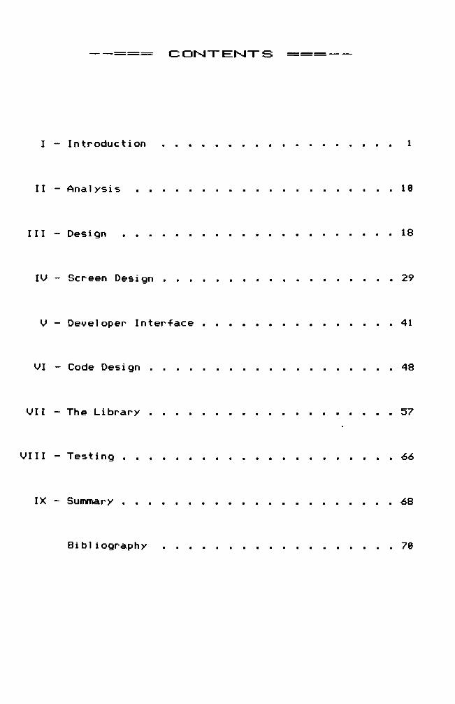
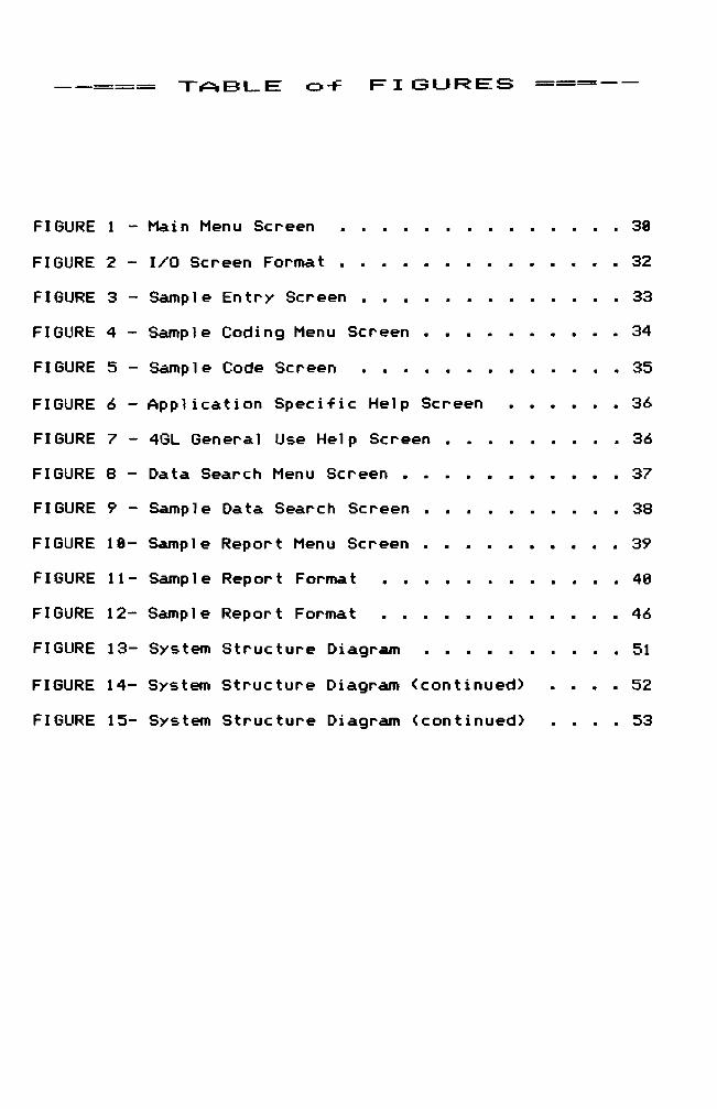
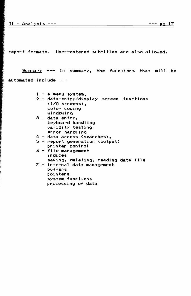
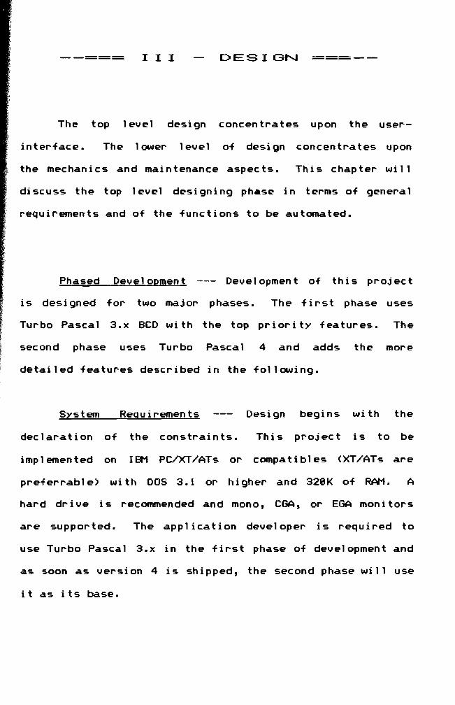
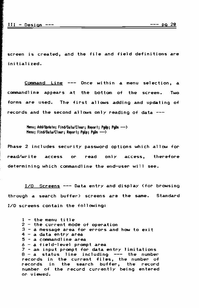
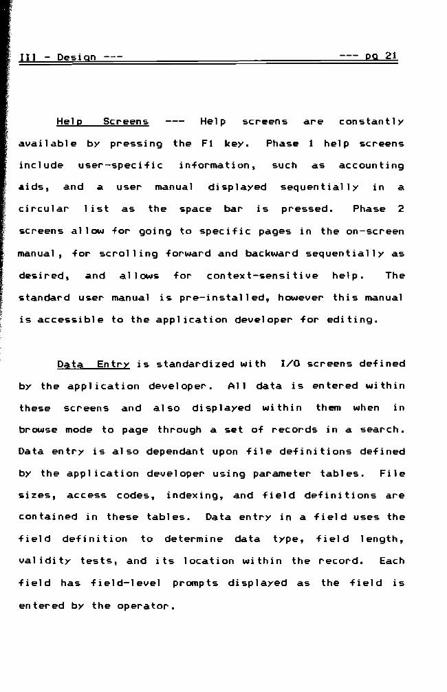