Download - Technical Specification - INIS Hydro

INIS HYDRO Seabed Mapping Technical
Specification
INIS Hydro is a project supported by the European Union's INTERREG IVA Programme
managed by the Special EU Programmes Body.
INIS HYDRO Seabed Mapping Technical Specification
Project Summary 1
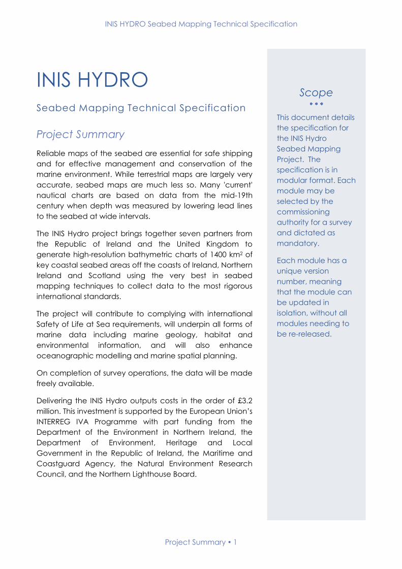
INIS HYDRO
Seabed Mapping Technical Specification
Project Summary
Reliable maps of the seabed are essential for safe shipping
and for effective management and conservation of the
marine environment. While terrestrial maps are largely very
accurate, seabed maps are much less so. Many 'current'
nautical charts are based on data from the mid-19th
century when depth was measured by lowering lead lines
to the seabed at wide intervals.
The INIS Hydro project brings together seven partners from
the Republic of Ireland and the United Kingdom to
generate high-resolution bathymetric charts of 1400 km2 of
key coastal seabed areas off the coasts of Ireland, Northern
Ireland and Scotland using the very best in seabed
mapping techniques to collect data to the most rigorous
international standards.
The project will contribute to complying with international
Safety of Life at Sea requirements, will underpin all forms of
marine data including marine geology, habitat and
environmental information, and will also enhance
oceanographic modelling and marine spatial planning.
On completion of survey operations, the data will be made
freely available.
Delivering the INIS Hydro outputs costs in the order of £3.2
million. This investment is supported by the European Union’s
INTERREG IVA Programme with part funding from the
Department of the Environment in Northern Ireland, the
Department of Environment, Heritage and Local
Government in the Republic of Ireland, the Maritime and
Coastguard Agency, the Natural Environment Research
Council, and the Northern Lighthouse Board.
Scope
This document details
the specification for
the INIS Hydro
Seabed Mapping
Project. The
specification is in
modular format. Each
module may be
selected by the
commissioning
authority for a survey
and dictated as
mandatory.
Each module has a
unique version
number, meaning
that the module can
be updated in
isolation, without all
modules needing to
be re-released.

INIS HYDRO Seabed Mapping Technical Specification
Contents 2
Contents
Scope .................................................................................................................................................... 1
Project Summary .................................................................................................................................. 1
Modules ................................................................................................................................................ 4
A ............................................................................................................................................................. 8
Module A1 – Personnel ....................................................................................................................... 9
Module A2 – Planning & Progress .................................................................................................... 12
Module A3 – Safety ........................................................................................................................... 15
Module A4 – Deliverables ................................................................................................................. 20
B ........................................................................................................................................................... 24
Module B1 – Multibeam Bathymetry IHO Order 1a ...................................................................... 25
C........................................................................................................................................................... 31
Module C1 – Dynamic Positioning .................................................................................................. 32
Module C2 – Static Positioning for Survey Control ........................................................................ 38
Module C3 – Optical Levelling ........................................................................................................ 46
Module C4 – Station Marking and Descriptions ............................................................................ 50
D ........................................................................................................................................................... 54
Module D1 – Coastal and Offshore Tide Gauges ......................................................................... 55
Module D2 – Reduction of Soundings - GNSS and VORF ............................................................ 60
Module D3 – Reduction of Soundings - Tidal Data ....................................................................... 64
E ............................................................................................................................................................ 67
Module E1 – Water Column Measurements .................................................................................. 68
F ............................................................................................................................................................ 73
Module F1 – Wreck Investigations ................................................................................................... 74
Module F2 - Seabed Sampling ........................................................................................................ 78
Module F3 - Seabed Classification ................................................................................................. 82
G .......................................................................................................................................................... 87
Module G1 – Navigational Data ..................................................................................................... 88

INIS HYDRO Seabed Mapping Technical Specification
Record of Changes 3
Record of Changes
The table below documents the version history of the INIS Hydro seabed
mapping technical specification. The INIS Hydro Project Director has final sign
off on all changes made to the specification as a whole or the modules
contained herein.
Version Date Status Approved Signature
0.1 (Draft) 10.10.2012 Working draft - -
1.0 19.4.2013 First Release AVC

INIS HYDRO Seabed Mapping Technical Specification
Modules 4
Modules
The INIS Hydro Seabed Mapping Specification contains the modules
outlined below. The current version number, issue date and the INIS Hydro
survey requirement for each module are shown:
Module Title
Current
Version
Number
Issue
Date
Module
Required
A - Mandatory Modules
A1 - Personnel 1 19.04.2013
A2 - Planning & Progress 1 19.04.2013
A3 - Safety 1 19.04.2013
A4 - Deliverables 1 19.04.2013
B - Bathymetry
B1 - MBES to IHO 1a 1 19.04.2013
C - Positioning and Survey Control
C1 - Dynamic Positioning 1 19.04.2013
C2 - Static Positioning for Survey
Control 1 19.04.2013
C3 - Optical Levelling 1 19.04.2013
C4 - Station Marking and Descriptions 1 19.04.2013
D - Tidal Data and Reduction of
Soundings
D1 - Coastal and Offshore Tide Gauges 1 19.04.2013
D2 - Reduction of Soundings - GNSS
and VORF 1 19.04.2013
HI1351,
1354, 1355
D3 - Reduction of Soundings - Tidal
Data 1 19.04.2013
HI1353,
1362
E - Environmental Data
E1 - Water Column 1 19.04.2013
F - Seabed Features and Contacts
F1 - Wreck Investigations 1 19.04.2013
F2 - Seabed Sampling 1 19.04.2013
F3 - Seabed Classification 1 19.04.2013
G - Additional Data for Charting
G1 – Navigational Data 1 19.04.2013
INIS HYDRO Seabed Mapping Technical Specification
Symbols & Abbreviated Terms 5
Symbols & Abbreviated Terms
ADCP Acoustic Doppler Current Profiler
AFBI Agri-Food and Biosciences Institute
CD Chart Datum
CORS Continuously Operating Reference Station
DGPS Differential Global Positioning System
ETRS89 European Terrestrial Reference System 1989
FIG Féderération Internationale des Géometres
GDOP Geometric Dilution of Precision
GNSS Global Navigation Satellite System
GPS Global Positioning System
GRS80 Geodetic Reference System 1980
GSF Generic Sensor Format
GSI Geological Survey of Ireland
HI Hydrographic Instruction
HMOG Hydrographic & Meteorological Operational Guidance
IHO International Hydrographic Organization
IMCA International Marine Contractors Association
MBES Multibeam Echosounder
MCA Maritime & Coastguard Agency
MI Irish Marine Institute
MSL Mean Sea Level
NLB Northern Lighthouse Board
OD Ordnance Datum
PPP Precise Point Positioning
RICS Royal Institution of Chartered Surveyors

INIS HYDRO Seabed Mapping Technical Specification
Symbols & Abbreviated Terms 6
RINEX Receiver Independent Exchange Format
RoS Report of Survey
RTK Real Time Kinematic
SAMS Scottish Association for Marine Science
UKHO United Kingdom Hydrographic Office
USB Universal Serial Bus
UTM Universal Transverse Mercator
VORF Vertical Offshore Reference Frame
WADGPS Wide Area DGPS (i.e. multiple reference station)

INIS HYDRO Seabed Mapping Technical Specification
Acknowledgements 7
Acknowledgements
1. UK Civil Hydrography Programme Survey Specification v1.3 – 5/10/12
Maritime and Coastguard Agency

INIS HYDRO Seabed Mapping Technical Specification
MANDATORY
MODULESA

INIS HYDRO Seabed Mapping Technical Specification
Module A1 – Personnel 9
Module A1 – Personnel
1. Introduction
This module of the INIS Hydro Seabed Mapping Specification details the
requirements of personnel.
2. Related Standards and Documents
The relevant sections of the following documents are to be adhered to in full
in conjunction with this module;
Name Version
Number
Date of
Issue Comment
Standards for Hydrographic
Surveys. Special Publication
No. 44
Edition 5 February
2008
3. Related Modules
Module Number Module Title
A2 Planning & Progress
A3 Safety

INIS HYDRO Seabed Mapping Technical Specification
Module A1 – Personnel 10
4. Module Author
Suggested amendments or updates should be sent to:
Organisation: Maritime & Coastguard Agency
Email: [email protected]
5. Record of Changes
Version Date Status Approved Signature
0.1 (Draft) 10.10.2012 Working draft - -
1.0 19.4.2013 First Release AVC
INIS HYDRO Seabed Mapping Technical Specification
Module A1 – Personnel 11
6. Requirements
Code Title Description
A1 - 1 Charge Surveyor
A Charge Surveyor (Party Chief/Surveyor in
Charge) shall be on site at all times during
survey operations.
The Charge Surveyor shall possess an IHO/FIG
Category A accredited qualification (or
equivalent) with a minimum of 5 years offshore
surveying experience including surveying for
Nautical Charting purposes.
The Charge Surveyor shall have the authority
and experience to make and implement
operational decisions and will be available for
project partners to contact regularly to assess
progress and modify the survey plan if
necessary.
The Charge Surveyor’s other duties and
responsibilities shall be arranged such that they
do not interfere with the management of the
project.
A1 - 2 Survey Team
The Partner shall be able to list the number,
qualifications and experience of the survey
personnel and provide these to other project
partners at any time.
Survey teams will include personnel with
adequate experience both in charge of and in
assisting with all aspects of surveys of complex
offshore areas for nautical charting purposes,
including office data compilation as well as
fieldwork.
INIS HYDRO Seabed Mapping Technical Specification
Module A2 – Planning & Progress 12
Module A2 – Planning & Progress
1. Introduction
This module of the INIS Hydro Seabed Mapping Specification details the
planning and progress requirements.
2. Related Standards and Documents
The relevant sections of the following documents are to be adhered to in full
in conjunction with this module;
Name Version
Number
Date of
Issue Comment
Standards for Hydrographic
Surveys. Special Publication
No. 44
Edition 5 February
2008
3. Related Modules
Module Number Module Title
A1 Personnel
A3 Safety

INIS HYDRO Seabed Mapping Technical Specification
Module A2 – Planning & Progress 13
4. Module Author
Suggested amendments or updates should be sent to:
Organisation: Maritime & Coastguard Agency
Email: [email protected]
5. Record of Changes
Version Date Status Approved Signature
0.1 (Draft) 10.10.2012 Working draft - -
1.0 19.4.2013 First Release AVC

INIS HYDRO Seabed Mapping Technical Specification
Module A2 – Planning & Progress 14
6. Requirements
Code Title Description
A2 - 1 Permissions
The Partner shall be responsible for arranging all
permits, permissions and licenses for access and
frequency clearance for all survey operations
whether ashore or afloat.
A2 - 2 Fishing Industry
Liaison with, and compensation to, fishermen for
loss/damage to fishing gear are matters which
rest entirely with the Partner. The Partner is to
liaise closely with local fisheries groups and the
appropriate local District Fisheries Inspectors well
in advance of the commencement of fieldwork.
A2 - 3 Daily and Weekly
Progress Report
Progress reports detailing progress, planned
activities, weather downtime and any problems
encountered shall be completed and e-mailed
to the MCA on a daily basis.
A short (e.g. 1-page) summary progress report
shall be completed and e-mailed to the MCA
Project Manager and Project partner manager
on a weekly basis.
A2 - 4 Quality Control
Robust quality control procedures shall be
provided and adhered to during processing of
all data. These procedures shall be available to
other project partners.
A2 - 5 Portable electronic
media
The Partner shall provide all media required for
transferring data from ship to shore and for
rendering completed surveys to the UKHO.
INIS HYDRO Seabed Mapping Technical Specification
Module A3 – Safety 15
Module A3 – Safety
1. Introduction
This module of the INIS Hydro Seabed Mapping Specification details the
safety requirements.
2. Related Standards and Documents
The relevant sections of the following documents are to be adhered to in full
in conjunction with this module;
Name Version
Number
Date of
Issue Comment
Standards for Hydrographic
Surveys. Special Publication
No. 44
Edition 5 February
2008
3. Related Modules
Module Number Module Title
A1 Personnel
A2 Planning & Progress

INIS HYDRO Seabed Mapping Technical Specification
Module A3 – Safety 16
4. Module Author
Suggested amendments or updates should be sent to:
Organisation: Maritime & Coastguard Agency
Email: [email protected]
5. Record of Changes
Version Date Status Approved Signature
0.1 (Draft) 10.10.2012 Working draft - -
1.0 19.4.2013 First Release AVC

INIS HYDRO Seabed Mapping Technical Specification
Module A3 – Safety 17
6. Requirements
Code Title Description
A3 - 1 Responsibility
Equipment and survey personnel provided by
the Partner for work in connection with the
project shall be the Partner's responsibility at all
times. The said equipment and survey personnel
and any loss, injury or damage suffered or
caused by them shall be at the Partner's risk
throughout.
A3 - 2 Safety
Management Plan
Partners shall have a safety policy and Safety
Management Plan which can be made
available to other project partners at any time.
A3 - 3 Drugs and Alcohol
Policy
The Partner shall have a drugs and alcohol
policy, which forbids the presence of drugs or
alcohol in vessels or offices used under this
project. Other project partners may ask for
evidence of the regime in place at any time
throughout the life of the project.
A3 - 4 Daily Meetings
The Surveyor-In-Charge shall hold daily “Toolbox
Meetings” with members of the navigational
watch. Meetings shall be minuted (briefly),
posted in the mess and shall include the
following headings as a minimum:
Date, Time, List of attendees
Activities - Last 24 Hours
Planned Activities – Next 24 Hours
Safety / Hazards
A3 - 5 Work in poorly
surveyed waters
The vessel master is responsible for the overall
navigational safety of the vessel and crew. If
the master considers that there is a conflict of
interest in terms of the safety of the vessel and
crew with regard to the proposed survey areas,
he has the overriding authority to refuse to
survey those areas.
A3 - 6 Medical
Certification
All offshore survey personnel must have an in-
date medical certificate of at least “ENG1”
standard. Evidence of certification may be
asked for by other project partners at any time.

INIS HYDRO Seabed Mapping Technical Specification
Module A3 – Safety 18
A3 - 7 Safety Training
Certification
All offshore survey personnel must have in-date
certification to demonstrate completion of the
STCW 95 Basic Safety Training package
including:
Personal Survival Techniques (STCW A-VI /
1-1)
Fire Fighting and Fire Prevention (STCW A-
VI / 1-2)
Elementary First Aid (STCW A-VI/ 1-3)
Personal Safety and Social
Responsibility(SCTW A- VI/1 – 4)
(Note that survey personnel and
supernumeraries may alternatively have in-date
certification to demonstrate completion of an
Offshore Petroleum Industry Training
Organisation approved course adhering to the
“Minimum Industry Safety Training Standards”).
Evidence of certification may be asked for by
other project partners at any time.
INIS HYDRO Seabed Mapping Technical Specification
Module A3 – Safety 19
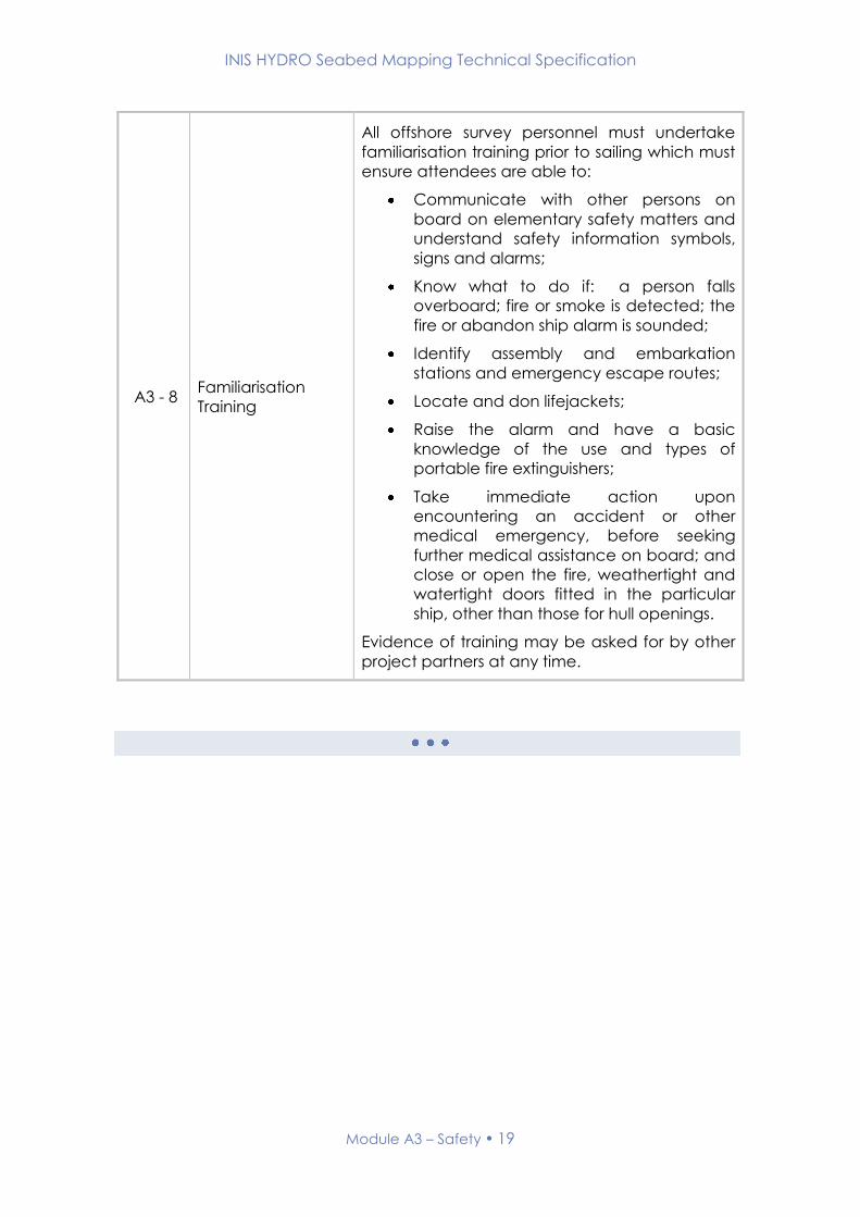
A3 - 8 Familiarisation
Training
All offshore survey personnel must undertake
familiarisation training prior to sailing which must
ensure attendees are able to:
Communicate with other persons on
board on elementary safety matters and
understand safety information symbols,
signs and alarms;
Know what to do if: a person falls
overboard; fire or smoke is detected; the
fire or abandon ship alarm is sounded;
Identify assembly and embarkation
stations and emergency escape routes;
Locate and don lifejackets;
Raise the alarm and have a basic
knowledge of the use and types of
portable fire extinguishers;
Take immediate action upon
encountering an accident or other
medical emergency, before seeking
further medical assistance on board; and
close or open the fire, weathertight and
watertight doors fitted in the particular
ship, other than those for hull openings.
Evidence of training may be asked for by other
project partners at any time.
INIS HYDRO Seabed Mapping Technical Specification
Module A4 – Deliverables 20
Module A4 – Deliverables
1. Introduction
This module of the INIS Hydro Seabed Mapping Specification details the
deliverables requirements.
2. Related Standards and Documents
The relevant sections of the following documents are to be adhered to in full
in conjunction with this module;
Name Version
Number
Date of
Issue Comment
Standards for Hydrographic
Surveys. Special Publication
No. 44
Edition 5 February
2008
3. Related Modules
None

INIS HYDRO Seabed Mapping Technical Specification
Module A4 – Deliverables 21
4. Module Author
Suggested amendments or updates should be sent to:
Organisation: Maritime & Coastguard Agency
Email: [email protected]
5. Record of Changes
Version Date Status Approved Signature
0.1 (Draft) 10.10.2012 Working draft - -
1.0 19.4.2013 First Release AVC
INIS HYDRO Seabed Mapping Technical Specification
Module A4 – Deliverables 22
6. Requirements
Code Title Description
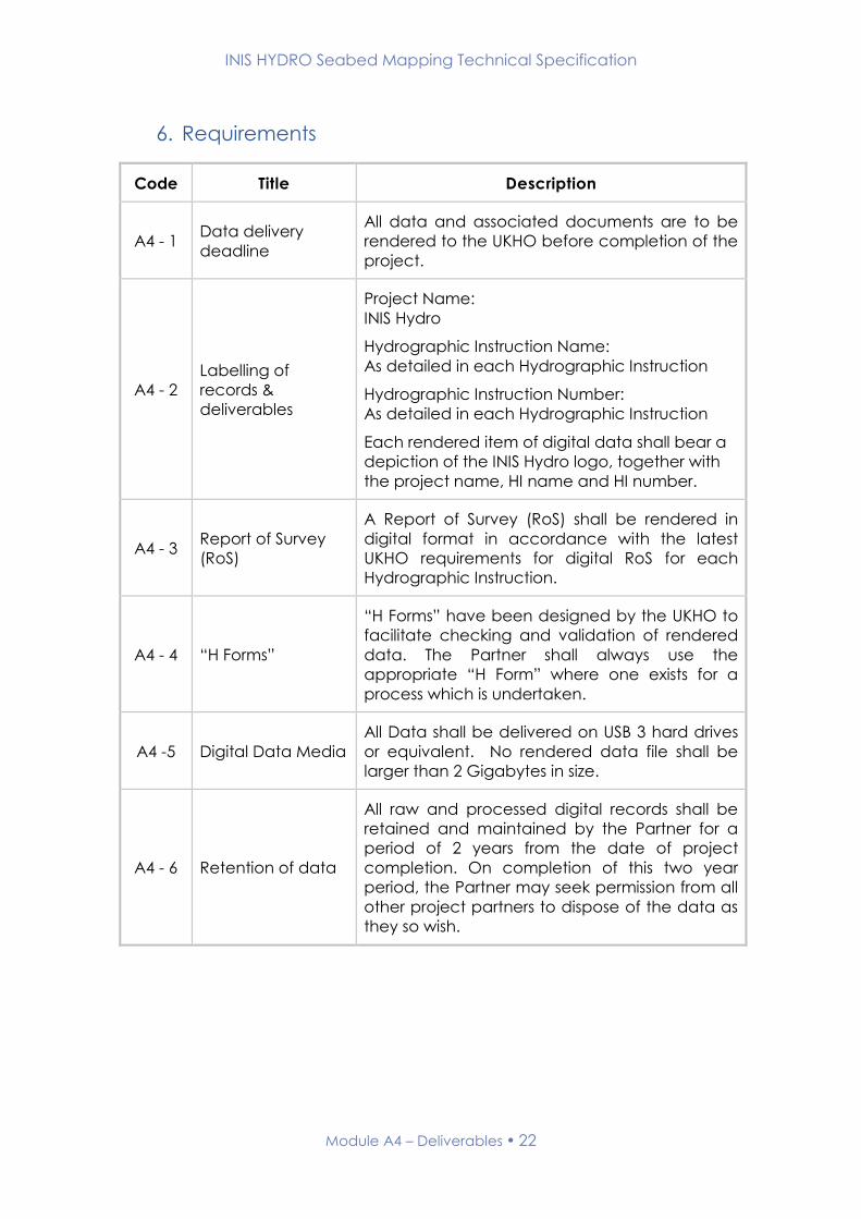
A4 - 1 Data delivery
deadline
All data and associated documents are to be
rendered to the UKHO before completion of the
project.
A4 - 2
Labelling of
records &
deliverables
Project Name:
INIS Hydro
Hydrographic Instruction Name:
As detailed in each Hydrographic Instruction
Hydrographic Instruction Number:
As detailed in each Hydrographic Instruction
Each rendered item of digital data shall bear a
depiction of the INIS Hydro logo, together with
the project name, HI name and HI number.
A4 - 3 Report of Survey
(RoS)
A Report of Survey (RoS) shall be rendered in
digital format in accordance with the latest
UKHO requirements for digital RoS for each
Hydrographic Instruction.
A4 - 4 “H Forms”
“H Forms” have been designed by the UKHO to
facilitate checking and validation of rendered
data. The Partner shall always use the
appropriate “H Form” where one exists for a
process which is undertaken.
A4 -5 Digital Data Media
All Data shall be delivered on USB 3 hard drives
or equivalent. No rendered data file shall be
larger than 2 Gigabytes in size.
A4 - 6 Retention of data
All raw and processed digital records shall be
retained and maintained by the Partner for a
period of 2 years from the date of project
completion. On completion of this two year
period, the Partner may seek permission from all
other project partners to dispose of the data as
they so wish.

INIS HYDRO Seabed Mapping Technical Specification
Module A4 – Deliverables 23
A4 - 7 Data ownership
All data and accompanying documents and
records, both working and fair, originating from
the survey become the property of the
European Union and must be handed over on
demand. Where appropriate, they are to carry
the following official markings:
"A project supported by the European Union's
INTERREG IVA Programme managed by the
Special EU Programmes Body."

INIS HYDRO Seabed Mapping Technical Specification
BATHYMETRY
MODULESB
INIS HYDRO Seabed Mapping Technical Specification
Module B1 – MBES IHO Order 1a 25
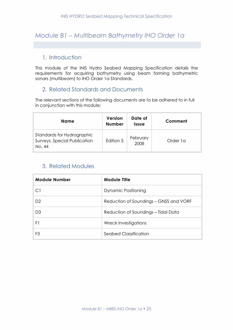
Module B1 – Multibeam Bathymetry IHO Order 1a
1. Introduction
This module of the INIS Hydro Seabed Mapping Specification details the
requirements for acquiring bathymetry using beam forming bathymetric
sonars (multibeam) to IHO Order 1a Standards.
2. Related Standards and Documents
The relevant sections of the following documents are to be adhered to in full
in conjunction with this module;
Name Version
Number
Date of
Issue Comment
Standards for Hydrographic
Surveys. Special Publication
No. 44
Edition 5 February
2008 Order 1a
3. Related Modules
Module Number Module Title
C1 Dynamic Positioning
D2 Reduction of Soundings – GNSS and VORF
D3 Reduction of Soundings – Tidal Data
F1 Wreck Investigations
F3 Seabed Classification

INIS HYDRO Seabed Mapping Technical Specification
Module B1 – MBES IHO Order 1a 26
4. Module Author
Suggested amendments or updates should be sent to:
Organisation: UK Hydrographic Office
Email: [email protected]
5. Record of Changes
Version Date Status Approved Signature
0.1 (Draft) 10.10.2012 Working draft - -
1.0 19.4.2013 First Release AVC
INIS HYDRO Seabed Mapping Technical Specification
Module B1 – MBES IHO Order 1a 27
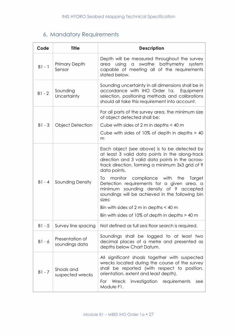
6. Mandatory Requirements
Code Title Description
B1 - 1 Primary Depth
Sensor
Depth will be measured throughout the survey
area using a swathe bathymetry system
capable of meeting all of the requirements
stated below.
B1 - 2 Sounding
Uncertainty
Sounding uncertainty in all dimensions shall be in
accordance with IHO Order 1a. Equipment
selection, positioning methods and calibrations
should all take this requirement into account.
B1 - 3 Object Detection
For all parts of the survey area, the minimum size
of object detected shall be:
Cube with sides of 2 m in depths < 40 m
Cube with sides of 10% of depth in depths > 40
m
B1 - 4 Sounding Density
Each object (see above) is to be detected by
at least 3 valid data points in the along-track
direction and 3 valid data points in the across-
track direction, forming a minimum 3x3 grid of 9
data points.
To monitor compliance with the Target
Detection requirements for a given area, a
minimum sounding density of 9 accepted
soundings will be achieved in the following bin
sizes:
Bin with sides of 2 m in depths < 40 m
Bin with sides of 10% of depth in depths > 40 m
B1 - 5 Survey line spacing Not defined as full sea floor search is required.
B1 - 6 Presentation of
soundings data
Soundings shall be logged to at least two
decimal places of a metre and presented as
depths below Chart Datum.
B1 - 7 Shoals and
suspected wrecks
All significant shoals together with suspected
wrecks located during the course of the survey
shall be reported (with respect to position,
orientation, extent and least depth).
For Wreck investigation requirements see
Module F1.

INIS HYDRO Seabed Mapping Technical Specification
Module B1 – MBES IHO Order 1a 28
B1 - 8 Backscatter
Full backscatter (format will depend on the
sonar manufacturer) shall be recorded at all
times during data acquisition.
Gain, pulse length or any other system changes
that affect backscatter intensities shall be
minimised throughout the survey.
B1 - 9 Data Cleaning
All accepted soundings within the final
bathymetric dataset shall fall within the IHO
Order 1a uncertainty allowance. All systematic
errors and obvious outliers shall be rejected from
the bathymetric data. Data points falling within
the Order 1a depth requirements but still
numerically distant from the main dataset will
still be regarded as outliers, and should be
rejected.
B1 - 10 Crosslines
A minimum of 4 bathymetric crosslines shall be
run for each Hydrographic Instruction, at
approximately equal spacing, with an optimum
of 4 crosslines for each survey block. These
crosslines shall be approximately perpendicular
to the typical mainline orientation in that block.
Crosslines shall be rendered in folders separate
from the mainline data structure, and the data
should be cleaned to allow for a statistical
analysis.
A statistical analysis between a cross-line and
the main data set is not required in the RoS – the
UKHO will undertake their own analysis against
compliancy with IHO depth accuracies.
7. Optional Requirements
None
INIS HYDRO Seabed Mapping Technical Specification
Module B1 – MBES IHO Order 1a 29
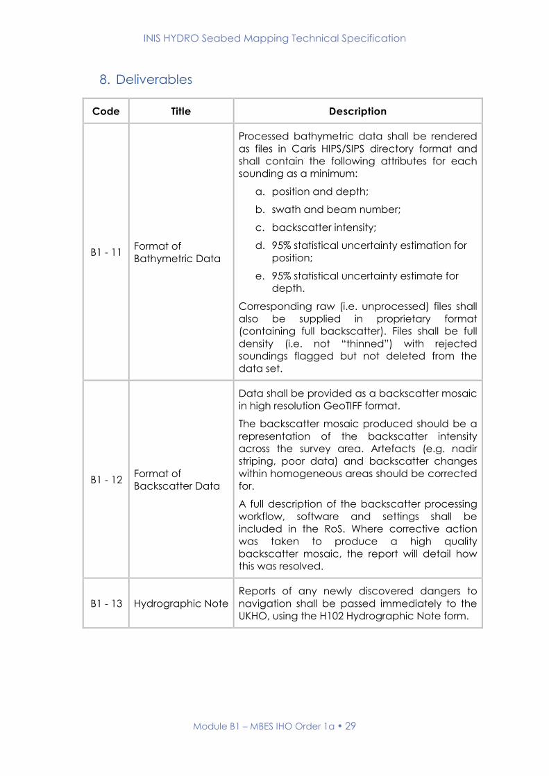
8. Deliverables
Code Title Description
B1 - 11 Format of
Bathymetric Data
Processed bathymetric data shall be rendered
as files in Caris HIPS/SIPS directory format and
shall contain the following attributes for each
sounding as a minimum:
a. position and depth;
b. swath and beam number;
c. backscatter intensity;
d. 95% statistical uncertainty estimation for
position;
e. 95% statistical uncertainty estimate for
depth.
Corresponding raw (i.e. unprocessed) files shall
also be supplied in proprietary format
(containing full backscatter). Files shall be full
density (i.e. not “thinned”) with rejected
soundings flagged but not deleted from the
data set.
B1 - 12 Format of
Backscatter Data
Data shall be provided as a backscatter mosaic
in high resolution GeoTIFF format.
The backscatter mosaic produced should be a
representation of the backscatter intensity
across the survey area. Artefacts (e.g. nadir
striping, poor data) and backscatter changes
within homogeneous areas should be corrected
for.
A full description of the backscatter processing
workflow, software and settings shall be
included in the RoS. Where corrective action
was taken to produce a high quality
backscatter mosaic, the report will detail how
this was resolved.
B1 - 13 Hydrographic Note
Reports of any newly discovered dangers to
navigation shall be passed immediately to the
UKHO, using the H102 Hydrographic Note form.

INIS HYDRO Seabed Mapping Technical Specification
Module B1 – MBES IHO Order 1a 30
B1 - 14 Comparison with
published charts
The sounding detail shown on the largest scale
published UKHO chart of the survey area is to be
critically examined and any significant
differences reported. In particular, a comment
is required for any charted dangers that were
not discovered during the survey, or where the
least depth found over a danger during the
survey is deeper than charted. Any other errors,
ambiguities or other defects shall be reported.

INIS HYDRO Seabed Mapping Technical Specification
POSITIONING
AND SURVEY
CONTROL
MODULES
C

INIS HYDRO Seabed Mapping Technical Specification
Module C1 – Dynamic Positioning 32
Module C1 – Dynamic Positioning
1. Introduction
This module of the INIS Hydro Seabed Mapping Specification details the
requirements for acquiring three dimensional dynamic position using Global
Navigation Satellite Systems (GNSS).
2. Related Standards and Documents
The relevant sections of the following documents are to be adhered to in full
in conjunction with this module;
Name Version
Number
Date of
Issue Comment
Standards for Hydrographic
Surveys. Special Publication
No. 44
Edition 5 February
2008
Guidelines for the use of GNSS
in land surveying and
mapping. RICS Guidance
Note.
Edition 2 Nov 2010 www.rics.org
Guidelines for GNSS positioning
in the oils and gas industry –
IMCA S 015
Report
No. 373-
19
June
2011 www.imca-int.com
3. Related Modules
Module Number Module Title
B Bathymetry
D2 Reduction of Soundings – GNSS and VORF
D3 Reduction of Soundings – Tidal Data

INIS HYDRO Seabed Mapping Technical Specification
Module C1 – Dynamic Positioning 33
4. Module Author
Suggested amendments or updates should be sent to:
Organisation: UK Hydrographic Office
Email: [email protected]
5. Record of Changes
Version Date Status Approved Signature
0.1 (Draft) 10.10.2012 Working draft - -
1.0 19.4.2013 First Release AVC

INIS HYDRO Seabed Mapping Technical Specification
Module C1 – Dynamic Positioning 34
6. Mandatory Requirements
Code Title Description
C1 - 1
Vessel Positioning
(utilising GNSS
Height)
If the use of GNSS height and VORF model for
reduction of soundings to datum has been
specified by the commissioning agency, three
dimensional positions for the vessel and all
related sensors are to be derived using dual
frequency carrier phase GNSS observations
combined with the relevant Ordnance Survey
Active Network. This will derive positions referred
to the ETRS89 coordinate reference system.
Local reference stations may also be
established if the relevant Ordnance Survey
Active Network is insufficient in the survey area.
These stations must meet all the requirements
outlined in Sections C & D.
If, in a given area, the above methodology
proves unreliable, the surveyor may use Precise
Point Positioning (PPP) as a secondary
alternative.
C1 - 2
Vessel Positioning
(not utilising GNSS
Height)
If the use of GNSS height and VORF model for
reduction of soundings to datum has not been
specified by the commissioning agency, then as
a minimum differential GNSS meeting the
requirements stated in this Module is to be
utilised for establishment of horizontal position.
C1 - 3 Position
Uncertainty
Position uncertainty in all dimensions to be in
accordance with the specified bathymetry
module requirements (e.g Module B1 – MBES
IHO Order 1a). Equipment selection, positioning
methods and calibrations should all take this
requirement into account.
INIS HYDRO Seabed Mapping Technical Specification
Module C1 – Dynamic Positioning 35
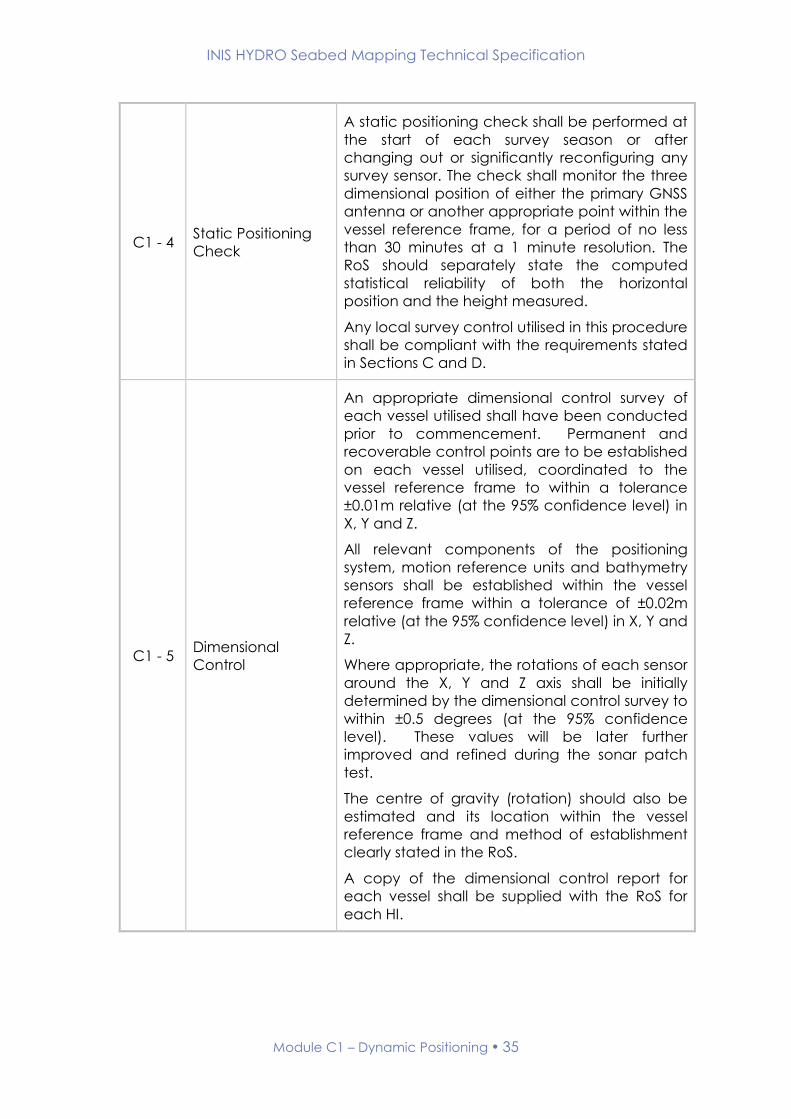
C1 - 4 Static Positioning
Check
A static positioning check shall be performed at
the start of each survey season or after
changing out or significantly reconfiguring any
survey sensor. The check shall monitor the three
dimensional position of either the primary GNSS
antenna or another appropriate point within the
vessel reference frame, for a period of no less
than 30 minutes at a 1 minute resolution. The
RoS should separately state the computed
statistical reliability of both the horizontal
position and the height measured.
Any local survey control utilised in this procedure
shall be compliant with the requirements stated
in Sections C and D.
C1 - 5 Dimensional
Control
An appropriate dimensional control survey of
each vessel utilised shall have been conducted
prior to commencement. Permanent and
recoverable control points are to be established
on each vessel utilised, coordinated to the
vessel reference frame to within a tolerance
±0.01m relative (at the 95% confidence level) in
X, Y and Z.
All relevant components of the positioning
system, motion reference units and bathymetry
sensors shall be established within the vessel
reference frame within a tolerance of ±0.02m
relative (at the 95% confidence level) in X, Y and
Z.
Where appropriate, the rotations of each sensor
around the X, Y and Z axis shall be initially
determined by the dimensional control survey to
within ±0.5 degrees (at the 95% confidence
level). These values will be later further
improved and refined during the sonar patch
test.
The centre of gravity (rotation) should also be
estimated and its location within the vessel
reference frame and method of establishment
clearly stated in the RoS.
A copy of the dimensional control report for
each vessel shall be supplied with the RoS for
each HI.

INIS HYDRO Seabed Mapping Technical Specification
Module C1 – Dynamic Positioning 36
C1 - 6 Repeatability Test
A sounding Repeatability Test shall be
performed at the start of each survey season or
after changing out or significantly reconfiguring
any survey sensor. This test should be conducted
after the static check stated above.
The test shall monitor the three dimensional
position of a clearly defined small but easily
detectable feature on the seabed. The feature
should be first surveyed near nadir from multiple
directions – as a minimum from north, south,
east and west. Secondly the feature should be
boxed in, so that it appears in the outer beams
on port for 2 lines, and the outer beams on
starboard for 2 lines.
The RoS should separately state the computed
statistical reliability of both the horizontal
position and the depth measured for the
feature.
7. Optional Requirements
None
INIS HYDRO Seabed Mapping Technical Specification
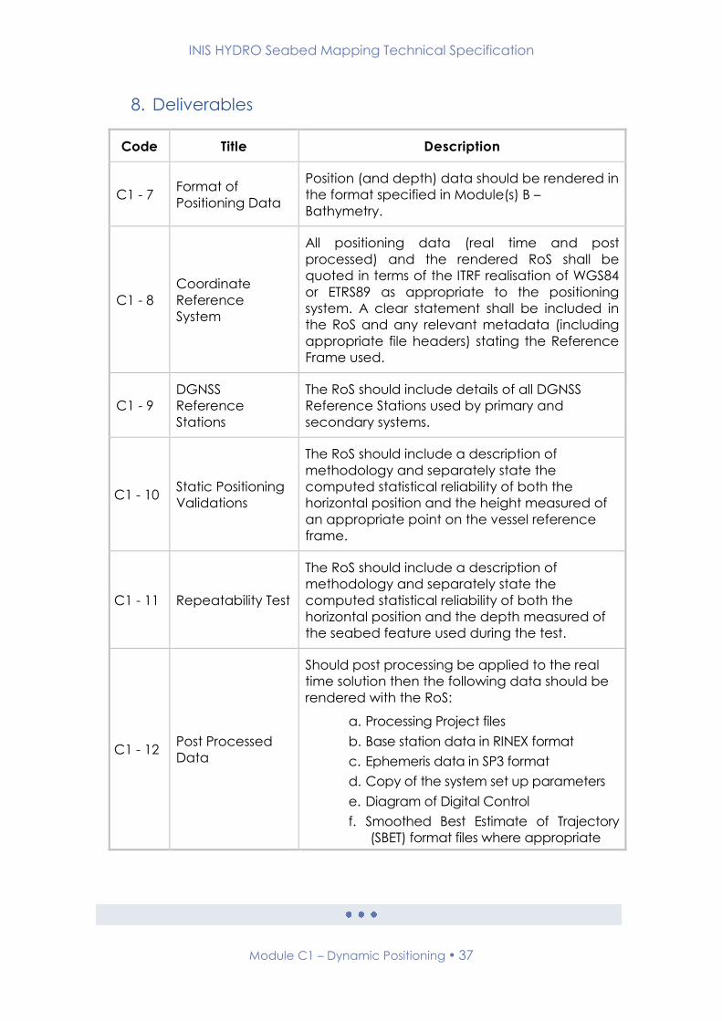
Module C1 – Dynamic Positioning 37
8. Deliverables
Code Title Description
C1 - 7 Format of
Positioning Data
Position (and depth) data should be rendered in
the format specified in Module(s) B –
Bathymetry.
C1 - 8
Coordinate
Reference
System
All positioning data (real time and post
processed) and the rendered RoS shall be
quoted in terms of the ITRF realisation of WGS84
or ETRS89 as appropriate to the positioning
system. A clear statement shall be included in
the RoS and any relevant metadata (including
appropriate file headers) stating the Reference
Frame used.
C1 - 9
DGNSS
Reference
Stations
The RoS should include details of all DGNSS
Reference Stations used by primary and
secondary systems.
C1 - 10 Static Positioning
Validations
The RoS should include a description of
methodology and separately state the
computed statistical reliability of both the
horizontal position and the height measured of
an appropriate point on the vessel reference
frame.
C1 - 11 Repeatability Test
The RoS should include a description of
methodology and separately state the
computed statistical reliability of both the
horizontal position and the depth measured of
the seabed feature used during the test.
C1 - 12 Post Processed
Data
Should post processing be applied to the real
time solution then the following data should be
rendered with the RoS:
a. Processing Project files
b. Base station data in RINEX format
c. Ephemeris data in SP3 format
d. Copy of the system set up parameters
e. Diagram of Digital Control
f. Smoothed Best Estimate of Trajectory
(SBET) format files where appropriate

INIS HYDRO Seabed Mapping Technical Specification
Module C2 – Static Positioning for Survey Control 38
Module C2 – Static Positioning for Survey Control
1. Introduction
This module of the INIS Hydro Seabed Mapping Specification details the
requirements for establishing survey control using static Global Navigation
Satellite Systems (GNSS) observations.
2. Related Standards and Documents
The relevant sections of the following documents are to be adhered to in full
in conjunction with this module;
Name Version
Number
Date of
Issue Comment
Standards for Hydrographic
Surveys. Special Publication
No. 44
Edition 5 February
2008
Guidelines for the use of GNSS
in land surveying and
mapping. RICS Guidance
Note.
Edition 2 Nov 2010 www.rics.org
Virtually Level. RICS Geomatics
and Ordnance Survey
Guidance Leaflet.
www.rics.org
3. Related Modules
Module Number Module Title
C3 Optical Levelling
C4 Station Marking and Descriptions

INIS HYDRO Seabed Mapping Technical Specification
Module C2 – Static Positioning for Survey Control 39
4. Module Author
Suggested amendments or updates should be sent to:
Organisation: UK Hydrographic Office
Email: [email protected]
5. Record of Changes
Version Date Status Approved Signature
0.1 (Draft) 10.10.2012 Working draft - -
1.0 19.4.2013 First Release AVC

INIS HYDRO Seabed Mapping Technical Specification
Module C2 – Static Positioning for Survey Control 40
6. Mandatory Requirements
Code Title Description
C2 - 1 Geodetic Control
Geodetic GNSS observations are to be carried
out in support of hydrographic survey
operations. Control stations should be installed
as required for: use as new tidal benchmarks; as
a confidence check on the height of existing
benchmarks; to provide geodetic control for the
validation of dynamic positioning systems; to
extend existing geodetic control as required for
the establishment of GNSS reference stations
where required.
C2 - 2 Coordinate System
Geodetic control stations and tidal benchmarks
should be referred to the ETRS89 datum, GRS80
spheroid. Where any grid coordinates are
computed, the appropriate UTM grid zone
should be applicable to the area of survey.
Observations are to be tied in using
Continuously Operating Reference Station
(CORS) data appropriate to the survey area,
i.e.: Ordnance Survey Active Network;
Ordnance Survey Ireland Active Network; IGS
data. GNSS derived ellipsoid heights should be
converted to orthometric heights using
OSGM02. To prevent any misunderstandings or
any incorrect assumptions, the actual
coordinate reference system of the final co-
ordinates should be stated.
C2 - 3 Equipment Dual frequency, survey quality GNSS receivers
shall be used for all static GNSS observations.

INIS HYDRO Seabed Mapping Technical Specification
Module C2 – Static Positioning for Survey Control 41
C2 - 4 Observation
Method
Survey control shall be determined by ‘Static’
dual frequency carrier phase GNSS techniques.
GNSS stations shall be located with substantially
clear sky-view and not close to buildings or
other structures that might introduce multipath
effects.
A minimum of 5 satellites must be observed for
the full observation period, with a minimum
elevation mask of 10°. GDOP values must not
exceed 5 during the observation period.
The antenna shall be horizontally located using
an optical plummet and tribrach. The height of
the antenna above the survey control point
should be measured at the beginning and end
of each session and recorded and reported. If
the vertical reference level of the antenna is
offset in the horizontal (e.g. the outer lip of an
antenna plate), then the slope distance must
be corrected to compute the vertical offset
from the survey control point.
The antenna and receiver types and serial
numbers should be recorded and included in
the RoS. Each setup should be photographed
and included in the RoS.
C2 - 5 Observation Period
A minimum of six hours observations at 15
second (maximum) intervals are required per
station. This six hour observation period should
be divided into two three hour sessions. At the
end of the first session the antenna should be
physically moved away from the mark and then
re-established over the mark before
commencing the 2nd observation session.
C2 - 6 Redundancy
checks
As a gross error check, to confirm the vertical
performance of the separation model, and
potentially to tie in to pre-existing inconsistent
control used on older surveys, control points shall
be optically levelled from two pre-existing
control points referred to the appropriate
Ordnance Datum. In some cases, this levelling
requirement may be replaced by an entirely
GNSS based redundant technique upon
agreement with the INIS representative; for
example when pre-existing control proves
unsuitable or non-existent.

INIS HYDRO Seabed Mapping Technical Specification
Module C2 – Static Positioning for Survey Control 42
C2 - 7 Processing
Software
The processing software should be able to
process Static GNSS observations and be
capable of importing and using precise
ephemeris. The software should allow the use of
NGS antenna phase centre offset calibration
data.
C2 - 8 Processing Method
and Network
Adjustment
GNSS data from a minimum of four CORS
appropriate to the survey area, i.e.: Ordnance
Survey Active Network; Ordnance Survey
Ireland Active Network; IGS data, should be
used for processing the observation data. GNSS
baselines should be processed using precise
ephemeris to the following acceptance criteria:
a. Baselines <100km
b. Horizontal 0.02m+1ppm, Vertical
0.02m+1ppm
c. Baselines >100km
d. Horizontal 0.05m+1ppm, Vertical
0.10m+1ppm
The adjustment of the dataset is to be
performed in two stages. An unconstrained
network computation shall be run holding one
known point fixed. This shall demonstrate that
the network is internally consistent and can be
used to investigate other outlier baselines, using
the following tests:
e. Network Connectivity Test (ensures
that the network is well
connected).
f. Chi-square Test (a statistical
analysis to identify gross errors).
g. Tau Test (flags vectors for further
evaluation and manual editing).
h. Control Tie Analysis (performs an
analysis of the control positions)
If the results of the unconstrained computation
are acceptable, then a constrained
computation should be performed, holding all
control points fixed.
C2 - 9 Uncertainty
The absolute uncertainty with respect to ETRS89
for any existing or newly established survey
control shall not exceed 1cm in horizontal and 2
cm in vertical at the 95% confidence level.

INIS HYDRO Seabed Mapping Technical Specification
Module C2 – Static Positioning for Survey Control 43
C2 - 10 Booking Sheets Booking sheets containing all required site and
observation information should be completed
and retained by the surveyor.
7. Optional Requirements
None
INIS HYDRO Seabed Mapping Technical Specification
Module C2 – Static Positioning for Survey Control 44
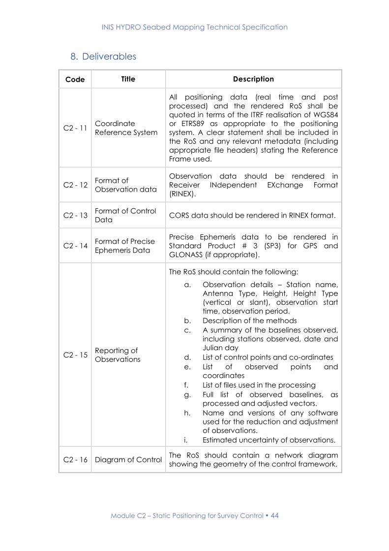
8. Deliverables
Code Title Description
C2 - 11 Coordinate
Reference System
All positioning data (real time and post
processed) and the rendered RoS shall be
quoted in terms of the ITRF realisation of WGS84
or ETRS89 as appropriate to the positioning
system. A clear statement shall be included in
the RoS and any relevant metadata (including
appropriate file headers) stating the Reference
Frame used.
C2 - 12 Format of
Observation data
Observation data should be rendered in
Receiver INdependent EXchange Format
(RINEX).
C2 - 13 Format of Control
Data CORS data should be rendered in RINEX format.
C2 - 14 Format of Precise
Ephemeris Data
Precise Ephemeris data to be rendered in
Standard Product # 3 (SP3) for GPS and
GLONASS (if appropriate).
C2 - 15 Reporting of
Observations
The RoS should contain the following:
a. Observation details – Station name,
Antenna Type, Height, Height Type
(vertical or slant), observation start
time, observation period.
b. Description of the methods
c. A summary of the baselines observed,
including stations observed, date and
Julian day
d. List of control points and co-ordinates
e. List of observed points and
coordinates
f. List of files used in the processing
g. Full list of observed baselines, as
processed and adjusted vectors.
h. Name and versions of any software
used for the reduction and adjustment
of observations.
i. Estimated uncertainty of observations.
C2 - 16 Diagram of Control The RoS should contain a network diagram
showing the geometry of the control framework.

INIS HYDRO Seabed Mapping Technical Specification
Module C2 – Static Positioning for Survey Control 45
C2 - 17
Baseline solutions,
network
adjustment results
and coordinates.
Copies of the reports produced by the geodetic
GNSS processing software should be rendered.
This data should contain copies of any
computed baseline solutions, the network
closures; final constrained network adjustment
and transformation parameters.
INIS HYDRO Seabed Mapping Technical Specification
Module C3 – Optical Levelling 46
Module C3 – Optical Levelling
1. Introduction
This module of the INIS Hydro Seabed Mapping Specification details the
requirements for optical levelling.
2. Related Standards and Documents
The relevant sections of the following documents are to be adhered to in full
in conjunction with this module;
Name Version
Number
Date of
Issue Comment
Standards for Hydrographic
Surveys. Special Publication
No. 44
Edition 5 February
2008
HM Operational Guidance
Volume 1 - Hydrography
HMOG
1/12
Admiralty Tidal Handbook No.
2,
Datums for Hydrographic
Surveys and other related
subjects
NP122(2)
3. Related Modules
Module Number Module Title
C4 Station Marking and Descriptions
D1 Coastal and Offshore Tide Gauges

INIS HYDRO Seabed Mapping Technical Specification
Module C3 – Optical Levelling 47
4. Module Author
Suggested amendments or updates should be sent to:
Organisation: UK Hydrographic Office
Email: [email protected]
5. Record of Changes
Version Date Status Approved Signature
0.1 (Draft) 10.10.2012 Working draft - -
1.0 19.4.2013 First Release AVC

INIS HYDRO Seabed Mapping Technical Specification
Module C3 – Optical Levelling 48
6. Mandatory Requirements
Code Title Description
C3 - 1 Purpose
As a gross error check, to confirm the vertical
performance of the separation model, and
potentially to tie in to pre-existing inconsistent
control used on older surveys, control points shall
be optically levelled from two pre-existing
control points referred to the appropriate
Ordnance Datum.
Levelling is also required to coordinate a tide
pole or tidal TBM to the local survey control.
In some cases, this levelling requirement may be
replaced by an entirely GNSS based redundant
technique upon agreement with the UKHO
representative; for example when pre-existing
control proves unsuitable or non-existent.
C3 - 2 Two Peg Test
A two peg test is to be conducted for each
instrument at each location to ensure the
instrument has not been damaged or rendered
out of calibration during transit.
C3 - 3 Method
Levelling is to comprise a looped traverse,
starting on the first known point and finishing on
the second.
Inter-sights are not to be used, as they offer no
redundancy.
C3 - 4 Precision Levels should be read and recorded to a
precision of 0.001m.
C3 - 5 Miscolsure The maximum acceptable misclosure for a
looped traverse is 0.02m.
7. Optional Requirements
None

INIS HYDRO Seabed Mapping Technical Specification
Module C3 – Optical Levelling 49
8. Deliverables
Code Title Description
C3 – 6 Pre-Existing Control
Where the HI refers to existing benchmarks a
report on their condition (or likely destruction if
not found) must be made, even if they are not
used in the eventual levelling operation.
C3 - 7
Form H535 –
Levelling
Reduction Form
Details of levelling to a tide pole or tidal TBM to
the local survey control are to be rendered on
Form H535.
INIS HYDRO Seabed Mapping Technical Specification
Module C4 – Station Marking and Descriptions 50
Module C4 – Station Marking and Descriptions
1. Introduction
This module of the INIS Hydro Seabed Mapping Specification details the
requirements for installing survey control points and the creation of station
description documentation.
2. Related Standards and Documents
The relevant sections of the following documents are to be adhered to in full
in conjunction with this module;
Name Version
Number
Date of
Issue Comment
Standards for Hydrographic
Surveys. Special Publication
No. 44
Edition 5 February
2008
3. Related Modules
Module Number Module Title
C2 Static Positioning for Survey Control
C3 Optical Levelling
D1 Coastal and Offshore Tide Gauges

INIS HYDRO Seabed Mapping Technical Specification
Module C4 – Station Marking and Descriptions 51
4. Module Author
Suggested amendments or updates should be sent to:
Organisation: UK Hydrographic Office
Email: [email protected]
5. Record of Changes
Version Date Status Approved Signature
0.1 (Draft) 10.10.2012 Working draft - -
1.0 19.4.2013 First Release AVC

INIS HYDRO Seabed Mapping Technical Specification
Module C4 – Station Marking and Descriptions 52
6. Requirements
Code Title Description
C4 - 1 Geodetic Stations
– Purpose
Geodetic control stations can be installed for:
use as new tidal benchmarks; as a confidence
check on the height of existing benchmarks; to
provide geodetic control for the validation of
dynamic positioning systems; to extend existing
geodetic control as required for the
establishment of GNSS reference stations.
C4 - 2 Permanent
Marking
All new geodetic stations shall be permanently
marked to assist in their future recovery. They
shall be marked with either a stainless steel
anchor bolt or a brass / bronze surveying bolt
drilled into concrete an area where they are
unlikely to be disturbed. Stations shall not be
established in tarmac. If the bolt is not an
expanding anchor type then epoxy resin or
similar should be used to secure.
The bolt shall be punched to mark the precise
horizontal measurement point.
C4 - 3 Temporary
Marking
In the event of a temporary mark being
required then in order to aid their recovery in
the short term they should be marked using
stainless steel nails (eg PK Nail or hilti nail);
wooden peg or stake; cut mark or punch mark
as appropriate to the surface in which they are
installed.
C4 - 4 Coordinate System
The coordinate system for geodetic control
stations and tidal benchmarks should be
referred to ETRS89 datum, GRS80 spheroid.
Where grid coordinates are computed, the
appropriate UTM grid zone should be
applicable to the area of survey. GNSS derived
ellipsoid heights should be converted to
orthometric heights using OSGM02. To prevent
any misunderstandings or any incorrect
assumptions, the actual system of the final co-
ordinates should be stated. Coordinates should
not be quoted to a greater precision than that
of the estimated error.
C4 - 5 Suitability for
Position Fixing
An assessment should be a made as to the
stations suitability as a site for position fixing
systems.
INIS HYDRO Seabed Mapping Technical Specification
Module C4 – Station Marking and Descriptions 53
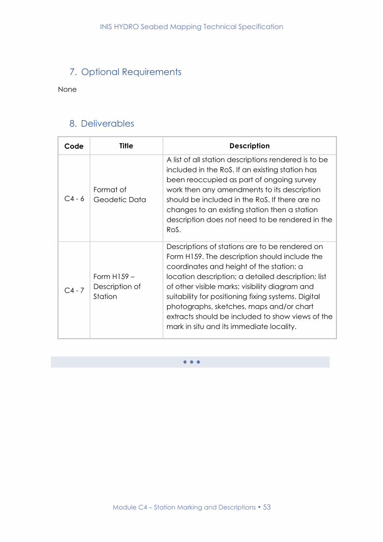
7. Optional Requirements
None
8. Deliverables
Code Title Description
C4 - 6
Format of
Geodetic Data
A list of all station descriptions rendered is to be
included in the RoS. If an existing station has
been reoccupied as part of ongoing survey
work then any amendments to its description
should be included in the RoS. If there are no
changes to an existing station then a station
description does not need to be rendered in the
RoS.
C4 - 7
Form H159 –
Description of
Station
Descriptions of stations are to be rendered on
Form H159. The description should include the
coordinates and height of the station; a
location description; a detailed description; list
of other visible marks; visibility diagram and
suitability for positioning fixing systems. Digital
photographs, sketches, maps and/or chart
extracts should be included to show views of the
mark in situ and its immediate locality.

INIS HYDRO Seabed Mapping Technical Specification
TIDAL DATA
AND
REDUCTION
OF
SOUNDINGS
MODULES
D

INIS HYDRO Seabed Mapping Technical Specification
Module D1 – Coastal and Offshore Tide Gauges 55
Module D1 – Coastal and Offshore Tide Gauges
1. Introduction
This module of the INIS Hydro Seabed Mapping Specification details the
requirements for establishing coastal and offshore tide gauges.
2. Related Standards and Documents
The relevant sections of the following documents are to be adhered to in full
in conjunction with this module;
Name Version
Number
Date of
Issue Comment
Standards for Hydrographic
Surveys. Special Publication
No. 44
Edition 5 February
2008
HM Operational Guidance
Volume 1 - Hydrography HMOG Re-issued annually
Admiralty Tidal Handbook No.
2 NP122 (2)
3. Related Modules
Module Number Module Title
B Bathymetry
C1 Dynamic Positioning
C2 Static Positioning for Survey Control
C3 Optical Levelling
C4 Station Marking and Descriptions
D3 Reduction of Soundings – Tidal Data
INIS HYDRO Seabed Mapping Technical Specification
Module D1 – Coastal and Offshore Tide Gauges 56
4. Module Author
Suggested amendments or updates should be sent to:
Organisation: UK Hydrographic Office
Email: [email protected]
5. Record of Changes
Version Date Status Approved Signature
0.1 (Draft) 10.10.2012 Working draft - -
1.0 19.4.2013 First Release AVC

INIS HYDRO Seabed Mapping Technical Specification
Module D1 – Coastal and Offshore Tide Gauges 57
6. Mandatory Requirements
Code Title Description
D1 - 1 Locations
Tidal heights will normally be required to be
measured throughout the survey period and for
a minimum of 30 days using a temporary or
permanent tide gauge capable of meeting all
of the requirements stated below. The
location(s) of required tide gauge(s) will be
stated in the HI.
D1 - 2 Measurement
Uncertainty
All automatic tide gauges (both onshore and
offshore) should be capable of resolving water
level with respect to the survey control (coastal)
or MSL (offshore) to within ±0.01m in height and
±2 min in time at the 95% confidence level for
the duration of the observation period. This
uncertainty shall include all of the measurement
uncertainty of any pole to gauge comparisons
conducted.
D1 - 3 Precision
Heights must be recorded to at least 2 decimal
places of precision and at time intervals of at
least 10 minutes.

INIS HYDRO Seabed Mapping Technical Specification
Module D1 – Coastal and Offshore Tide Gauges 58
D1 - 4
Coastal Gauges –
Pole to Gauge
Comparison
All coastal tide gauges must be calibrated by
reference to independent readings using a tide
pole or ‘top down air gap’ measurements from
a survey control point. Form H143 ‘Record of
Tidal Observations’ must be used for this
purpose to allow for both the transducer offset
from datum and the scale error of the gauge.
Readings are to be taken at 20 minutes
intervals, with 10-minute interval readings taken
for the duration of one hour before to one hour
after high and low water. If observing at a
location with a tide range larger than 6m, or
where the range is perceived to be changing
rapidly, the observations are to be taken every
10 minutes, and every 5 minutes for the duration
of one hour before to one hour after high and
low water.
Reports on the Pole to Gauge comparison are
to be recorded using the H516 ‘Summary of
Checks on Automatic Tide Gauge’ form.
When a permanent / established tide gauge is
used, a pole to gauge comparison must still be
undertaken, unless documented evidence that
this check has recently (within the last 6 months)
been undertaken by an appropriate owning
authority.
D1 - 5
Coastal Gauges –
Connection to
Survey Control
All survey control points used to coordinate
coastal tide gauges shall comply with the
requirements stated in Section C.
7. Optional Requirements
D1 - 6 Transfer of Datum
In some cases, the Surveyor may be required to
establish a tide gauge at a Standard or
Secondary Port, levelled in to Ordnance Datum,
and perform a transfer of datum for a minimum
of a 39 hour period between this gauge and
any newly established gauge in accordance
with Admiralty Tidal Handbook No2 [NP122(2)].
This requirement will be clearly stated in the HI
when necessary.
INIS HYDRO Seabed Mapping Technical Specification
Module D1 – Coastal and Offshore Tide Gauges 59
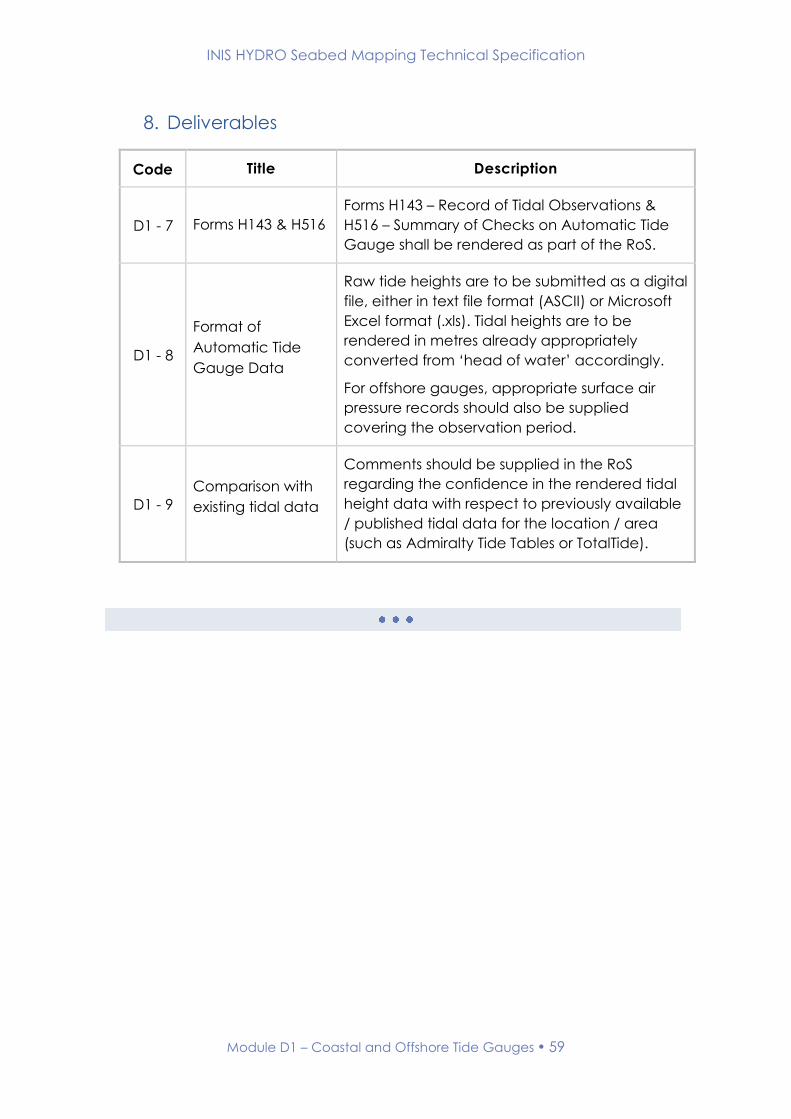
8. Deliverables
Code Title Description
D1 - 7 Forms H143 & H516
Forms H143 – Record of Tidal Observations &
H516 – Summary of Checks on Automatic Tide
Gauge shall be rendered as part of the RoS.
D1 - 8
Format of
Automatic Tide
Gauge Data
Raw tide heights are to be submitted as a digital
file, either in text file format (ASCII) or Microsoft
Excel format (.xls). Tidal heights are to be
rendered in metres already appropriately
converted from ‘head of water’ accordingly.
For offshore gauges, appropriate surface air
pressure records should also be supplied
covering the observation period.
D1 - 9
Comparison with
existing tidal data
Comments should be supplied in the RoS
regarding the confidence in the rendered tidal
height data with respect to previously available
/ published tidal data for the location / area
(such as Admiralty Tide Tables or TotalTide).

INIS HYDRO Seabed Mapping Technical Specification
Module D2 – Reduction of Soundings – GNSS and VORF 60
Module D2 – Reduction of Soundings - GNSS and
VORF
1. Introduction
This module of the INIS Hydro Seabed Mapping Specification details the
requirements for reducing soundings using GNSS and VORF.
2. Related Standards and Documents
The relevant sections of the following documents are to be adhered to in full
in conjunction with this module;
Name Version
Number
Date of
Issue Comment
Standards for Hydrographic
Surveys. Special Publication
No. 44
Edition 5 February
2008
3. Related Modules
Module Number Module Title
B Bathymetry
C1 Dynamic Positioning
D3 Reduction of Sounding – Tidal Data
INIS HYDRO Seabed Mapping Technical Specification
Module D2 – Reduction of Soundings – GNSS and VORF 61
4. Module Author
Suggested amendments or updates should be sent to:
Organisation: UK Hydrographic Office
Email: [email protected]
5. Record of Changes
Version Date Status Approved Signature
0.1 (Draft) 10.10.2012 Working draft - -
1.0 19.4.2013 First Release AVC
INIS HYDRO Seabed Mapping Technical Specification
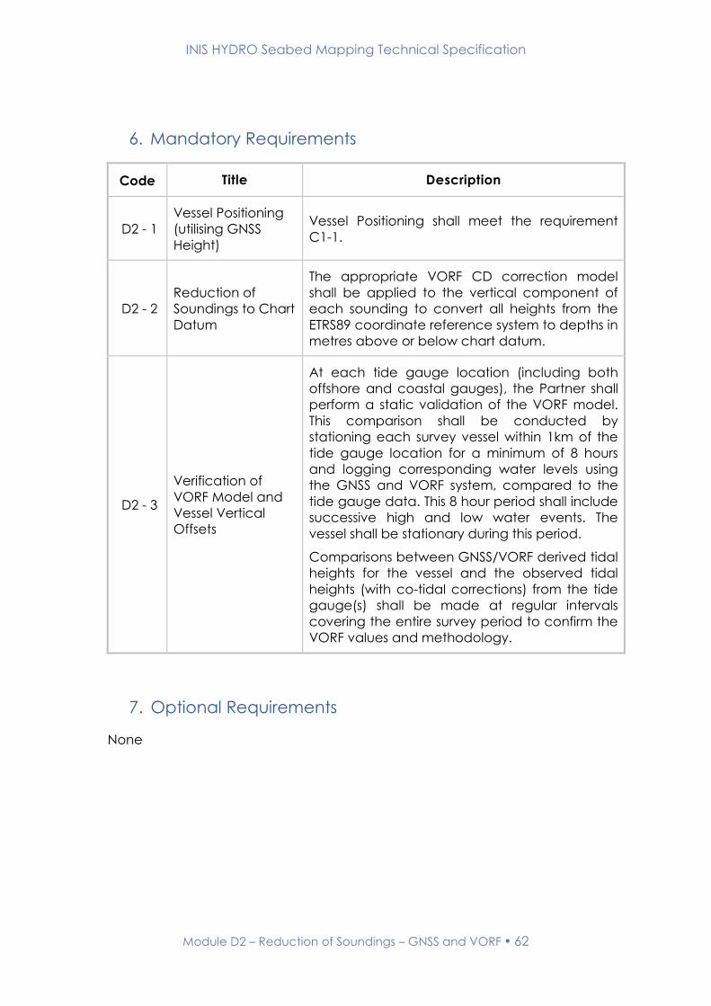
Module D2 – Reduction of Soundings – GNSS and VORF 62
6. Mandatory Requirements
Code Title Description
D2 - 1
Vessel Positioning
(utilising GNSS
Height)
Vessel Positioning shall meet the requirement
C1-1.
D2 - 2
Reduction of
Soundings to Chart
Datum
The appropriate VORF CD correction model
shall be applied to the vertical component of
each sounding to convert all heights from the
ETRS89 coordinate reference system to depths in
metres above or below chart datum.
D2 - 3
Verification of
VORF Model and
Vessel Vertical
Offsets
At each tide gauge location (including both
offshore and coastal gauges), the Partner shall
perform a static validation of the VORF model.
This comparison shall be conducted by
stationing each survey vessel within 1km of the
tide gauge location for a minimum of 8 hours
and logging corresponding water levels using
the GNSS and VORF system, compared to the
tide gauge data. This 8 hour period shall include
successive high and low water events. The
vessel shall be stationary during this period.
Comparisons between GNSS/VORF derived tidal
heights for the vessel and the observed tidal
heights (with co-tidal corrections) from the tide
gauge(s) shall be made at regular intervals
covering the entire survey period to confirm the
VORF values and methodology.
7. Optional Requirements
None

INIS HYDRO Seabed Mapping Technical Specification
Module D2 – Reduction of Soundings – GNSS and VORF 63
8. Deliverables
Code Title Description
D2 - 4 Bathymetry Data
All rendered bathymetry which has been
reduced to chart datum shall meet the
requirements stated in the relevant module in
Section B.
D2 - 5 VORF vs Tidal
Comparison
The results of the comparisons conducted in
requirement D2-3 should be presented in both
tabular and graphical format in the RoS.

INIS HYDRO Seabed Mapping Technical Specification
Module D3 – Reduction of Soundings – Tidal Data 64
Module D3 – Reduction of Soundings - Tidal Data
1. Introduction
This module of the INIS Hydro Seabed Mapping Specification details the
requirements for reducing soundings using tidal data.
2. Related Standards and Documents
The relevant sections of the following documents are to be adhered to in full
in conjunction with this module;
Name Version
Number
Date of
Issue Comment
Standards for Hydrographic
Surveys. Special Publication
No. 44
Edition 5 February
2008
3. Related Modules
Module Number Module Title
B Bathymetry
C1 Dynamic Positioning
D1 Coastal and Offshore Tide Gauges

INIS HYDRO Seabed Mapping Technical Specification
Module D3 – Reduction of Soundings – Tidal Data 65
4. Module Author
Suggested amendments or updates should be sent to:
Organisation: UK Hydrographic Office
Email: [email protected]
5. Record of Changes
Version Date Status Approved Signature
0.1 (Draft) 10.10.2012 Working draft - -
1.0 19.4.2013 First Release AVC

INIS HYDRO Seabed Mapping Technical Specification
Module D3 – Reduction of Soundings – Tidal Data 66
6. Mandatory Requirements
Code Title Description
D3 - 1
Vessel Positioning
(not utilising GNSS
Height)
Vessel Positioning shall meet the requirements
outlined in Module C1.
D3 - 2
Reduction of
Soundings to Chart
Datum
Observed tides meeting the requirements stated
in Module D1 shall be applied to all sounding
data, ensuring that all requirements stated in
Section B are met in full.
7. Optional Requirements
None
8. Deliverables
Code Title Description
D3 - 3 Bathymetry Data
All rendered bathymetry which has been
reduced to chart datum shall meet the
requirements stated in the relevant module in
Section B.

INIS HYDRO Seabed Mapping Technical Specification
ENVIRONMENTAL
DATA
MODULESE

INIS HYDRO Seabed Mapping Technical Specification
Module E1 – Water Column Measurements 68
Module E1 – Water Column Measurements
1. Introduction
This module of the INIS Hydro Seabed Mapping Specification details the water
column measurement requirements.
2. Related Standards and Documents
The relevant sections of the following documents are to be adhered to in full
in conjunction with this module;
Name Version
Number
Date of
Issue Comment
Standards for Hydrographic
Surveys. Special Publication
No. 44
Edition 5 February
2008
3. Related Modules
None

INIS HYDRO Seabed Mapping Technical Specification
Module E1 – Water Column Measurements 69
4. Module Author
Suggested amendments or updates should be sent to:
Organisation: UK Hydrographic Office
Email: [email protected]
5. Record of Changes
Version Date Status Approved Signature
0.1 (Draft) 10.10.2012 Working draft - -
1.0 19.4.2013 First Release AVC

INIS HYDRO Seabed Mapping Technical Specification
Module E1 – Water Column Measurements 70
6. Mandatory Requirements
Code Title Description
E1 - 1 Secchi Disk
Secchi depths are to be collected with an
appropriate Secchi disk – for freshwater
environments a 20cm black & white quartered
disk; for marine environments a 30 or 51 cm all-
white disk. Only one type of Secchi disk can be
used with a survey.
The Secchi disk should be lowered on the shady
side of the ship to reduce reflection from the sea
surface. The disc should be lowered into the
water on a marked lowering line with the ship
stopped and drifting. The marks on the lowering
line shall be at no greater than 0.5m intervals.
Reported Secchi measurements are preferably
collected at any point two hours before or after
noon. Secchi measurements are not
acceptable one hour after dawn or one hour
before dusk.
During Secchi collection, where possible, all
observations should be conducted by the same
member of survey staff. Where different
observers are used this shall be noted in the
deliverables.
Secchi depths are to be reported to the
decimetre or better.
Secchi disk observations shall be undertaken at
each sediment sampling location with a
spacing no greater than 5 km.
E1 - 2 Sound Speed
The Partner shall observe sound speed profiles
as and when required at an interval consistent
with the proposed error budget.
Evidence of calibration certification may be
asked for by other project partners at any time.

INIS HYDRO Seabed Mapping Technical Specification
Module E1 – Water Column Measurements 71
7. Optional Requirements
Code Title Description
E1 - 3 Water Column
measurements
Instruments shall be used to measure one or
more of the following water column attributes:
Conductivity
Temperature
Density
Salinity
Turbidity
Fluorimetry
Dissolved Oxygen
Measurements shall be undertaken at locations
and depths the Partner deems appropriate.
Evidence of calibration certification may be
asked for by other project partners at any time.

INIS HYDRO Seabed Mapping Technical Specification
Module E1 – Water Column Measurements 72
8. Deliverables
Code Title Description
E1 - 4 H631 Form
An H631 Secchi Disk Observations Reporting
Form shall be completed for all Secchi Disk
Observations.
E1 - 5 Format of Sound
Speed Data
Sound speed records shall be rendered in digital
format.
E1 - 6
Format of water
column
measurement
Data
Water column measurement records shall be
rendered in ASCII format as well as the
proprietary raw data format for the sensor
model utilised.

INIS HYDRO Seabed Mapping Technical Specification
SEABED
FEATURES &
CONTACTS
MODULES
F

INIS HYDRO Seabed Mapping Technical Specification
Module F1 – Wreck Investigations 74
Module F1 – Wreck Investigations
1. Introduction
This module of the INIS Hydro Seabed Mapping Specification details the
requirements for undertaking wreck investigations.
2. Related Standards and Documents
The relevant sections of the following documents are to be adhered to in full
in conjunction with this module;
Name Version
Number
Date of
Issue Comment
Standards for Hydrographic
Surveys. Special Publication
No. 44
Edition 5 February
2008
3. Related Modules
Module Number Module Title
B Bathymetry

INIS HYDRO Seabed Mapping Technical Specification
Module F1 – Wreck Investigations 75
4. Module Author
Suggested amendments or updates should be sent to:
Organisation: UK Hydrographic Office
Email: [email protected]
5. Record of Changes
Version Date Status Approved Signature
0.1 (Draft) 10.10.2012 Working draft - -
1.0 19.4.2013 First Release AVC
INIS HYDRO Seabed Mapping Technical Specification
Module F1 – Wreck Investigations 76
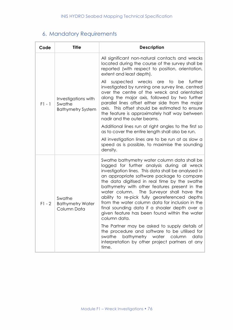
6. Mandatory Requirements
Code Title Description
F1 - 1
Investigations with
Swathe
Bathymetry System
All significant non-natural contacts and wrecks
located during the course of the survey shall be
reported (with respect to position, orientation,
extent and least depth).
All suspected wrecks are to be further
investigated by running one survey line, centred
over the centre of the wreck and orientated
along the major axis, followed by two further
parallel lines offset either side from the major
axis. This offset should be estimated to ensure
the feature is approximately half way between
nadir and the outer beams.
Additional lines run at right angles to the first so
as to cover the entire length shall also be run.
All investigation lines are to be run at as slow a
speed as is possible, to maximise the sounding
density.
F1 - 2
Swathe
Bathymetry Water
Column Data
Swathe bathymetry water column data shall be
logged for further analysis during all wreck
investigation lines. This data shall be analysed in
an appropriate software package to compare
the data digitised in real time by the swathe
bathymetry with other features present in the
water column. The Surveyor shall have the
ability to re-pick fully georeferenced depths
from the water column data for inclusion in the
final sounding data if a shoaler depth over a
given feature has been found within the water
column data.
The Partner may be asked to supply details of
the procedure and software to be utilised for
swathe bathymetry water column data
interpretation by other project partners at any
time.

INIS HYDRO Seabed Mapping Technical Specification
Module F1 – Wreck Investigations 77
7. Optional Requirements
Code Title Description
F1 - 3 Magnetometer
All suspected wrecks are to be investigated by
obtaining magnetometer data. A minimum of
two lines are required, one centred over the
centre of the wreck and orientated along the
major axis, and the second run at right angles to
the first across the minor axis.
The magnetometer shall be capable of
detecting deflections of 10 nano-Teslars from
the background noise.
Magnetometer data must be processed
onboard the vessel and magnetometer signal
strength overlaid, graphically, on a colour-
coded bathymetry plot in order to correlate
local magnetometer field distortions with
potential bathymetric features.
8. Deliverables
Code Title Description
F1 - 4 H525 Form An H525 Report of Wreck Investigation Form shall
be completed for each investigation.
F1 - 5 Format of Water
Column Data
Images or animations shall be supplied with the
RoS showing the water column replay for each
wreck to support the designation of least depth.
Raw and processed proprietary data formats for
all files shall also be rendered.
F1 - 6
Format of
Magnetometer
Data
Magnetometer data shall be supplied as an
electronic file containing lat, long and
magnetometer signal strength in a documented
file format.
INIS HYDRO Seabed Mapping Technical Specification
Module F2 – Seabed Sampling 78
Module F2 - Seabed Sampling
1. Introduction
This module of the INIS Hydro Seabed Mapping Specification details the
requirements for conducting seabed sampling.
2. Related Standards and Documents
The relevant sections of the following documents are to be adhered to in full
in conjunction with this module;
Name Version
Number
Date of
Issue Comment
Standards for Hydrographic
Surveys. Special Publication
No. 44
Edition 5 February
2008
3. Related Modules
Module Number Module Title
B Bathymetry
E1 Water Column Measurements
F3 Seabed Classification

INIS HYDRO Seabed Mapping Technical Specification
Module F2 – Seabed Sampling 79
4. Module Author
Suggested amendments or updates should be sent to:
Organisation: Maritime & Coastguard Agency
Email: [email protected]
5. Record of Changes
Version Date Status Approved Signature
0.1 (Draft) 10.10.2012 Working draft - -
1.0 19.4.2013 First Release AVC

INIS HYDRO Seabed Mapping Technical Specification
Module F2 – Seabed Sampling 80
6. Mandatory Requirements
Code Title Description
F2 - 1 Sampling
Resolution
Seabed sampling is to be conducted on an
approximate 5 km grid.
This grid shall be designed (once the area has
been fully surveyed) to target each major
textural area identified from backscatter data.
At least one sample shall be taken in each
major textural area identified.
Likely or charted anchorages shall also be
sampled irrespective of the wider sampling
regime.
A maximum of three attempts should be
conducted at each location in order for a
sample to be obtained.
F2 - 2 Sampling
Equipment
The sampling device should be appropriate for
the anticipated substratum (note that accurate
particle size analysis requires a minimum of
10,000 particles in the largest diameter class).
Samples are to be taken with the ship stopped
in the water or with samplers fitted with
underwater positioning equipment, e.g. USBL
(Ultra-Short Base-Line).
F2 - 3 Munsell Colour On recovery of a sample, the Munsell colour
shall be determined.
F2 - 4 Sample
Photographs
A photograph shall be taken of each sample on
a plain white background with a ruler or scale
bar clearly included.
F2 - 5 Sample
Classification
The surface substratum shall be documented
using the simplified Folk classification below:
Rock / Sediment Absent
Mud and sandy mud
Sand and muddy sand
Mixed sediment
Coarse sediment
Pelagic Ooze

INIS HYDRO Seabed Mapping Technical Specification
Module F2 – Seabed Sampling 81
F2 - 6 Sample
Preservation
Plastic screw top containers are to be used to
preserve the samples. The use of polythene
bags for preserving samples is not acceptable.
7. Optional Requirements
None
8. Deliverables
Code Title Description
F2 - 7 H575 Form An H575 Record of Seabed Samples and Cores
form shall be completed.
F2 - 8 Sample
Photographs
Photographs of each sample should
accompany the H575 form.
F2 - 9
Digital Data
Format of Seabed
Sampling
The surface substratum classified using the
simplified Folk classification must be rendered in
an ESRI Shape File format.
Each sample shall be expressed as a point and
shall contain the attributes included in the H575
form.
F2 - 10 Retained Seabed
Samples
Plastic screw top containers are to be used to
preserve the samples. The use of polythene
bags for preserving samples is not acceptable.
All samples are to be forward to a laboratory
undertaking a Nationally recognised external
quality control scheme, e.g. NMBAQC (National
Marine Biological Quality Assurance Quality
Control) or the British Geological Survey.
INIS HYDRO Seabed Mapping Technical Specification
Module F3 – Seabed Classification 82
Module F3 - Seabed Classification
1. Introduction
This module of the INIS Hydro Seabed Mapping Specification details the
requirements for classifying the texture of the seabed.
2. Related Standards and Documents
The relevant sections of the following documents are to be adhered to in full
in conjunction with this module;
Name Version
Number
Date of
Issue Comment
Standards for Hydrographic
Surveys. Special Publication
No. 44
Edition 5 February
2008
3. Related Modules
Module Number Module Title
B Bathymetry
F2 Seabed Sampling

INIS HYDRO Seabed Mapping Technical Specification
Module F3 – Seabed Classification 83
4. Module Author
Suggested amendments or updates should be sent to:
Organisation: Maritime & Coastguard Agency
Email: [email protected]
5. Record of Changes
Version Date Status Approved Signature
0.1 (Draft) 10.10.2012 Working draft - -
1.0 19.4.2013 First Release AVC
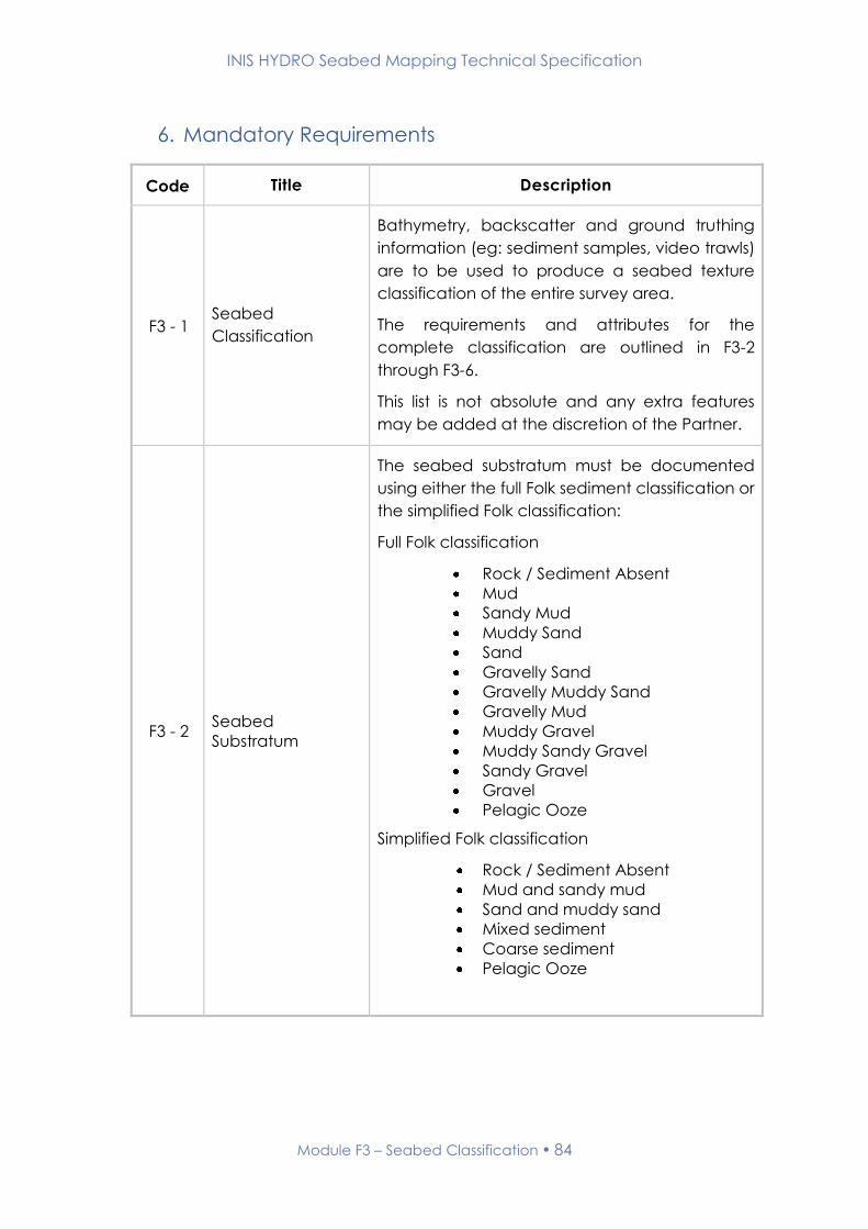
INIS HYDRO Seabed Mapping Technical Specification
Module F3 – Seabed Classification 84
6. Mandatory Requirements
Code Title Description
F3 - 1 Seabed
Classification
Bathymetry, backscatter and ground truthing
information (eg: sediment samples, video trawls)
are to be used to produce a seabed texture
classification of the entire survey area.
The requirements and attributes for the
complete classification are outlined in F3-2
through F3-6.
This list is not absolute and any extra features
may be added at the discretion of the Partner.
F3 - 2 Seabed
Substratum
The seabed substratum must be documented
using either the full Folk sediment classification or
the simplified Folk classification:
Full Folk classification
Rock / Sediment Absent
Mud
Sandy Mud
Muddy Sand
Sand
Gravelly Sand
Gravelly Muddy Sand
Gravelly Mud
Muddy Gravel
Muddy Sandy Gravel
Sandy Gravel
Gravel
Pelagic Ooze
Simplified Folk classification
Rock / Sediment Absent
Mud and sandy mud
Sand and muddy sand
Mixed sediment
Coarse sediment
Pelagic Ooze

INIS HYDRO Seabed Mapping Technical Specification
Module F3 – Seabed Classification 85
F3 - 3
Mobile Sediment
Areas
Areas of Mobile Sediment identified in the
survey area are to be documented using the
following feature types:
Sandwave Area
Ribbon Area
Ripple Area
F3 – 4
Other Seabed
Texture Areas
Areas of Seabed Texture identified in the survey
area that are not mobile sediment are to be
documented using the following feature types:
Scour Area
Thermal Vent Area
Vegetation Area
F3 – 5
Seabed Texture
line features
Seabed Texture features identified in the survey
area that can be represented as lines are to be
documented using the following feature types:
Sandwave Crest
Bedrock Scarp
Ridge
Cable
Scour Line
F3 – 6
Seabed Texture
point features
Seabed Texture features identified in the survey
area that can be represented as points are to
be documented using the following feature
types:
Sediment Sampling Point
Pockmark
Seabed Spring
Wreck (Charted & Non-Charted)
Sonar Contact (< 5 m)
Large Bottom Object (> 5 m other
than wreck)
Highly Reflective Patch
7. Optional Requirements
None
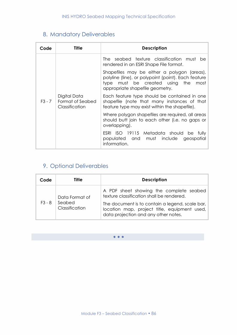
INIS HYDRO Seabed Mapping Technical Specification
Module F3 – Seabed Classification 86
8. Mandatory Deliverables
Code Title Description
F3 - 7
Digital Data
Format of Seabed
Classification
The seabed texture classification must be
rendered in an ESRI Shape File format.
Shapefiles may be either a polygon (areas),
polyline (line), or polypoint (point). Each feature
type must be created using the most
appropriate shapefile geometry.
Each feature type should be contained in one
shapefile (note that many instances of that
feature type may exist within the shapefile).
Where polygon shapefiles are required, all areas
should butt join to each other (i.e. no gaps or
overlapping).
ESRI ISO 19115 Metadata should be fully
populated and must include geospatial
information.
9. Optional Deliverables
Code Title Description
F3 - 8
Data Format of
Seabed
Classification
A PDF sheet showing the complete seabed
texture classification shall be rendered.
The document is to contain a legend, scale bar,
location map, project title, equipment used,
data projection and any other notes.
INIS HYDRO Seabed Mapping Technical Specification
ADDITIONAL
DATA FOR
CHARTING
MODULES
G
INIS HYDRO Seabed Mapping Technical Specification
Module G1 – Navigational Data 88
Module G1 – Navigational Data
1. Introduction
This module of the INIS Hydro Seabed Mapping Specification details the
navigational requirements.
2. Related Standards and Documents
The relevant sections of the following documents are to be adhered to in full
in conjunction with this module;
Name Version
Number
Date of
Issue Comment
Standards for Hydrographic
Surveys. Special Publication
No. 44
Edition 5 February
2008
3. Related Modules
None
INIS HYDRO Seabed Mapping Technical Specification
Module G1 – Navigational Data 89
4. Module Author
Suggested amendments or updates should be sent to:
Organisation: UK Hydrographic Office
Email: [email protected]
5. Record of Changes
Version Date Status Approved Signature
0.1 (Draft) 10.10.2012 Working draft - -
1.0 19.4.2013 First Release AVC
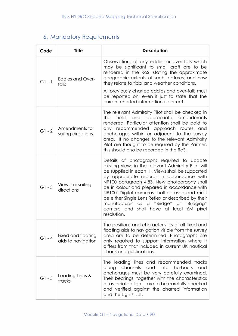
INIS HYDRO Seabed Mapping Technical Specification
Module G1 – Navigational Data 90
6. Mandatory Requirements
Code Title Description
G1 - 1 Eddies and Over-
falls
Observations of any eddies or over falls which
may be significant to small craft are to be
rendered in the RoS, stating the approximate
geographic extents of such features, and how
they relate to tidal and weather conditions.
All previously charted eddies and over-falls must
be reported on, even if just to state that the
current charted information is correct.
G1 - 2 Amendments to
sailing directions
The relevant Admiralty Pilot shall be checked in
the field and appropriate amendments
rendered. Particular attention shall be paid to
any recommended approach routes and
anchorages within or adjacent to the survey
area. If no changes to the relevant Admiralty
Pilot are thought to be required by the Partner,
this should also be recorded in the RoS.
G1 - 3 Views for sailing
directions
Details of photographs required to update
existing views in the relevant Admiralty Pilot will
be supplied in each HI. Views shall be supported
by appropriate records in accordance with
NP100 paragraph 4.83. New photography shall
be in colour and prepared in accordance with
NP100. Digital cameras shall be used and must
be either Single Lens Reflex or described by their
manufacturer as a “Bridge” or “Bridging”
camera and shall have at least 6M pixel
resolution.
G1 - 4 Fixed and floating
aids to navigation
The positions and characteristics of all fixed and
floating aids to navigation visible from the survey
area are to be determined. Photographs are
only required to support information where it
differs from that included in current UK nautical
charts and publications.
G1 - 5 Leading Lines &
tracks
The leading lines and recommended tracks
along channels and into harbours and
anchorages must be very carefully examined.
Their bearings, together with the characteristics
of associated lights, are to be carefully checked
and verified against the charted information
and the Lights' List.

INIS HYDRO Seabed Mapping Technical Specification
Module G1 – Navigational Data 91
G1 - 6 Light
characteristics
Light characteristics and sectors shall be
rendered. They are to be compared with the
entry in the current Admiralty List of Lights
Volume A NP74, amended to date. Light sectors
are to be checked against the entry in the
remarks column (column 8). Column 8 TE/(T)/(P)
remarks should also be confirmed or denied
especially the more historic entries. Any
amendments are to be noted in the RoS.
Significant changes which could lead to a
danger to navigation are to be reported
immediately to the UKHO.
All leading lights and light sectors must be
reported on, even if just to state that the current
charted information is correct.
G1 - 7 Magnetic
Anomalies
Charted or newly discovered magnetic
anomalies are to be investigated.
The ship should be steamed slowly in a wide
octagon shape centred on the charted
anomaly, both to port and starboard, made
with the standard magnetic compass on 8
equidistant points during each turn. The ship
should be steadied on each heading for at least
a minute before the observation to allow the
sub permanent magnetism resulting from the
last course, to disappear. On each leg of the
octagon, both magnetic and GNSS derived
headings shall be logged and compared.
Any anomaly found, or not found, shall be
reported in the RoS, including the extent and
magnitude of local variations.
7. Optional Requirements
None
INIS HYDRO Seabed Mapping Technical Specification
Module G1 – Navigational Data 92
8. Deliverables
Code Title Description
G1 - 8 Admiralty List of
Lights & Pilot
Amendments to the Admiralty List of Lights and
Admiralty Pilot shall be rendered in digital
format.
G1 - 9 Photographs Photographic views shall be rendered in digital
format.


