18/005/98
T
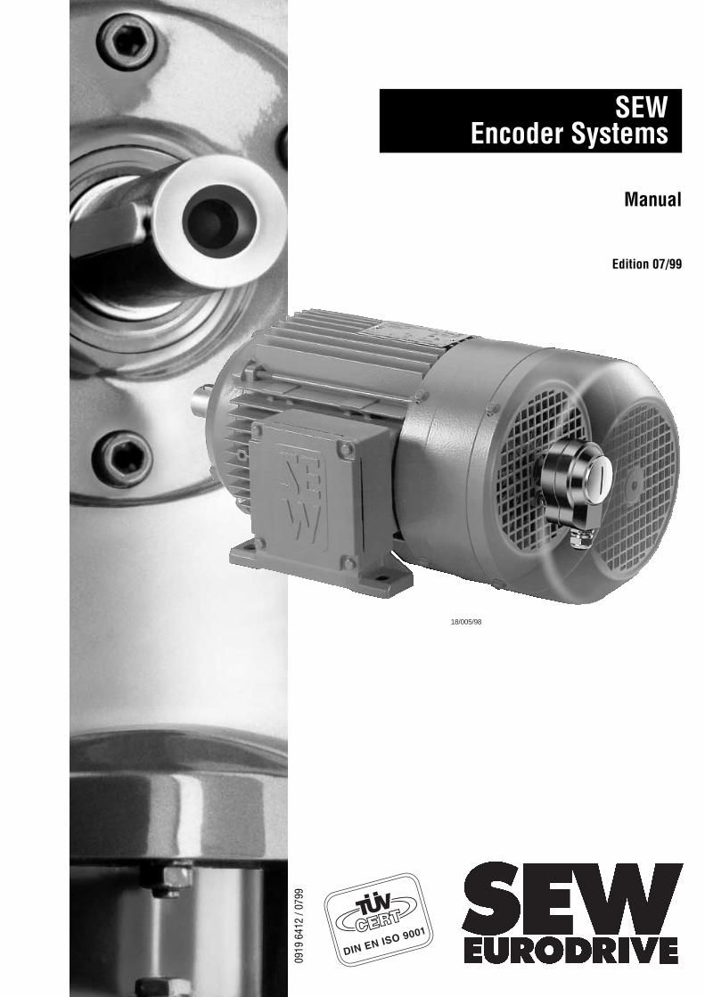
SEWEncoder Systems
Manual
Edition 07/99
0919
641
2 / 0
799
2 SEW encoder systems
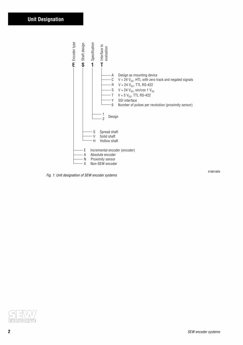
Unit Designation
01861AENFig. 1: Unit designation of SEW encoder systems
E S 1 T
E Incremental encoder (encoder)A Absolute encoderN Proximity sensorX Non-SEW encoder
S Spread shaftV Solid shaftH Hollow shaft
Enco
der t
ype
Shaf
t des
ign
Spec
ifica
tion
Inte
rfac
e to
eval
uatio
n
A Design as mounting deviceC V = 24 V , HTL with zero track and negated signalsR V = 24 V , TTL RS-422S V = 24 V , sin/cos 1 VT V = 5 V , TTL RS-422Y SSI interface6 Number of pulses per revolution (proximity sensor)
DC
DC
DC SS
DC
12 Design
Contents
SEW encoder systems 3
Page
1 System Description.....................................................................................41.1 System overview..............................................................................................................4
2 Technical Data ..........................................................................................72.1 Technical description .......................................................................................................7
2.1.1 Incremental encoders with TTL and HTL signals ...................................................72.1.2 Incremental encoders with high-resolution sin/cos signals...................................92.1.3 Absolute encoders with MSSI interface ...............................................................102.1.4 Resolver ..............................................................................................................122.1.5 Proximity sensors................................................................................................13
2.2 Incremental encoders ....................................................................................................142.2.1 Incremental encoders with spread shaft.............................................................. 142.2.2 Incremental encoders with solid shaft .................................................................15
2.3 Absolute encoder ........................................................................................................... 162.4 Resolver.........................................................................................................................172.5 Proximity sensors.......................................................................................................... 182.6 Mounting devices .......................................................................................................... 19
3 Installation............................................................................................. 203.1 General information .......................................................................................................203.2 Incremental encoders ....................................................................................................21
3.2.1 Encoders for MOVITRAC® 31C frequency inverters............................................ 213.2.2 Encoders for MOVIDRIVE® MDV60A drive inverters .........................................22
3.3 AV1Y absolute encoder.................................................................................................. 243.3.1 Absolute encoder with MOVIDYN® MAS/MKS51A servo controller..................243.3.2 Connection of absolute encoder to MOVIDRIVE® MDS60A drive inverter ........ 253.3.3 Absolute encoder with MOVIDRIVE® MDV60A drive inverter ............................25
3.4 Resolver.........................................................................................................................263.4.1 Resolver with MOVIDYN® MAS/MKS51A servo controller ..............................263.4.2 Resolver with MOVIDRIVE® MDS60A drive inverter.........................................27
3.5 Proximity sensors.......................................................................................................... 283.6 Extended motor versions with encoder and mounting devices ......................................29
3.6.1 Incremental encoders ES1_/ES2_/EV1_ .............................................................. 293.6.2 Encoder mounting devices ES1A/ES2A/EV1A......................................................313.6.3 Absolute encoder AV1Y.......................................................................................343.6.4 Encoder mounting devices AV1A.........................................................................36
3.7 Pre-fabricated cables .....................................................................................................37
4 SEW encoder systems
1 System Description
1 System Description
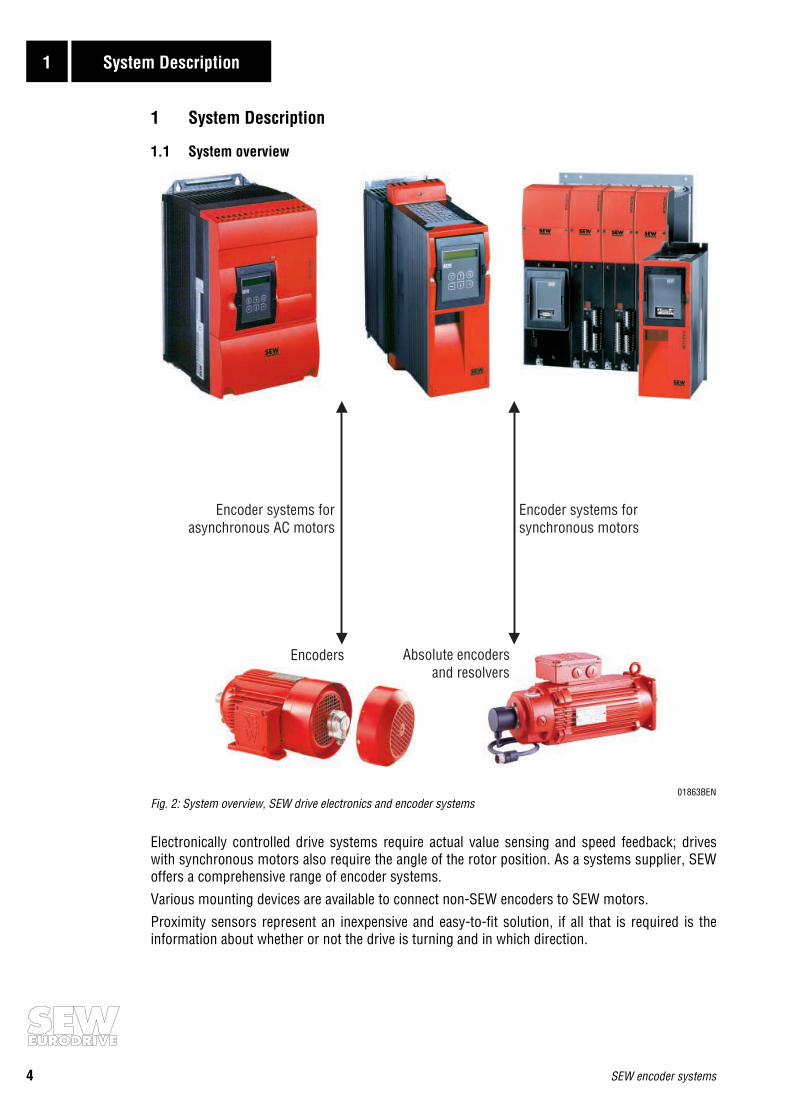
1.1 System overview
01863BENFig. 2: System overview, SEW drive electronics and encoder systems
Electronically controlled drive systems require actual value sensing and speed feedback; driveswith synchronous motors also require the angle of the rotor position. As a systems supplier, SEWoffers a comprehensive range of encoder systems.
Various mounting devices are available to connect non-SEW encoders to SEW motors.
Proximity sensors represent an inexpensive and easy-to-fit solution, if all that is required is theinformation about whether or not the drive is turning and in which direction.
Encoders Absolute encodersand resolvers
Encoder systems forasynchronous AC motors
Encoder systems forsynchronous motors
SEW encoder systems 5
System Description 1
SEW encoder systems for asynchronous AC motors:• Incremental encoders
- for 5 VDC supply voltage and with 5 V TTL signal level according to RS-422recommended for operation with the MOVITRAC® 31C frequency inverter
- for 24 VDC supply voltage and with high-resolution sinusoidal signal levelrecommended for operation with the MOVIDRIVE® drive inverter
- for 24 VDC supply voltage and with 5 V TTL signal level according to RS-422
- for 24 VDC supply voltage and with 24V HTL signal level• Absolute encoder
- for 15 VDC supply voltage and with MSSI interface
- for 24 VDC supply voltage and with MSSI interface and two sinusoidal tracks
• Proximity sensors- with six pulses per revolution
- with A track or A+B track
• Mounting devices for non-SEW encoders- mounting of spread shaft
- mounting of full shaft with coupling
SEW encoder systems for asynchronous servomotors:
• Incremental encoders
- for 24 VDC supply voltage and with high-resolution sinusoidal signal levelstandard feature in CT/CV motors
- for 24 VDC supply voltage and with 5 V TTL signal level according to RS-422• Absolute encoder
- for 24 VDC supply voltage and with MSSI interface and two sinusoidal tracks
SEW encoder systems for synchronous servomotors:
• Resolverstandard with synchronous servomotors for speed control
• Absolute encoder15/24 VDC supply voltage with MSSI interface
Encoder selection based on setting range:• Setting range up to 1:3000
- with asynchronous AC motors → encoder with TTL signals and1024 increments/revolution
- with synchronous motors → built-in resolver
• Setting range up to 1:5000
- with asynchronous AC motors → encoder with high-resolution sinusoidal signal levels- with asynchronous servomotors → encoder with high-resolution sinusoidal signal levels
6 SEW encoder systems
1 System Description
All encoder systems at a glance:
* recommended encoder for operation with MOVITRAC® 31C** recommended encoder for operation with MOVIDRIVE®
Mounting devices for non-SEW encoders
Name For SEW motorsize Type of encoder Shaft Specification Supply Signal
ES1T*
CT/DT71...100
Encoder
Spread shaft
-
5 VDC controlled 5 VDC TTL RS-422
ES1S**
24 VDC
1 VSS sin/cos
ES1C 24 VDC HTL
ES1R 5 VDC TTL RS-422
ES2T*
CV/DV112...132S
5 VDC controlled 5 VDC TTL RS-422
ES2S**
24 VDC
1 VSS sin/cos
ES2C 24 VDC HTL
ES2R 5 VDC TTL RS-422
EV1T*CT/CV71...180
DT/DV71...225Solid shaft
5 VDC controlled 5 VDC TTL RS-422
EV1S**
24 VDC
1 VSS sin/cos
EV1C 24 VDC HTL
EV1R 5 VDC TTL RS-422
NV16 DT/DV71...132S Proximity sensor Solid shaft
A track24 VDC
6 pulses/revolu-tion, NO contactNV26 A+B track
AV1Y
DS56DY71...112
CT/CV71...180DT/DV71...225
Absolute encoder Solid shaft - 15/24 VDCMSSI interface
and 1 VSS sin/cos
Name For SEW motorsize Type of encoder Shaft Specification Supply Signal
ES1A DT71...100
Non-SEW encoder
Spread shaft
- Configured as mounting device
ES2A DV112...132S
EV1A DT/DV71...225 Solid shaft
AV1A DS56, DY71...112 Solid shaft
XV1A DT/DV71...225 Solid shaft
SEW encoder systems 7
Technical Data 2
2 Technical Data
2.1 Technical description
This chapter explains the various types of signals, signal tracks and signal levels. The signal tracksare represented in the form of timing diagrams.
Encoders have a sturdy light metal housing and generously sized precision ball bearings. Theirsolid metal housing protects the encoders against interference, which lends them a high degree ofelectromagnetic compatibility.
2.1.1 Incremental encoders with TTL and HTL signals
Encoders convert the angle of rotation input parameter into a number of electrical pulses. This isperformed by means of an incremental disc incorporating radial slits permitting the passage oflight. These slits are scanned by opto-electronic means. The number of slits defines the resolution(pulses/revolution).
Signal tracks:SEW encoders are encoders with two tracks and one zero pulse track, which results in six tracksdue to negation. Two light barriers are arranged at right angles to one another in the encoder. Theysupply two pulse sequences on tracks A (K1) and B (K2). Track A (K1) is 90° ahead of B (K2) whenthe encoder is turning clockwise (to the right as viewed looking onto the motor shaft, the “A” side).This phase relationship is used for determining the direction of rotation of the motor. The zeropulse (one pulse per revolution) is sensed by a third light barrier and made available on track C(K0) as a reference signal. With TTL encoders, tracks A (K1), B (K2) and C (K0) are negated in theencoder and made available on tracks A (K1), B (K2) and C (K0) as negated signals.
01877AXXFig. 3: TTL signals with zero track and negated signals HTL signals with zero track, but without negated signals
90°
90°
180°360°
A (K1)
A K1( )
B (K2)
B K2( )
C (K0)
C K0( )
8 SEW encoder systems
2 Technical Data
Signal levels:• TTL (Transistor Transistor Logic) version
The signal levels are Vlow ≤ 0.5 V and Vhigh ≥ 2.5 V. The TTL signals are transmitted symmetri-cally and evaluated differentially. This design makes them resistant to asymmetrical interferenceand ensures good EMC behavior. The signal is transmitted in accordance with the RS-422 inter-face standard.Units with a 5 VDC encoder supply voltage, e.g. MOVITRAC® 31C, allow the user to measure theactual supply voltage at the encoder via sensor leads. The supply voltage is corrected to 5 VDCand compensates for the voltage drop along the supply cable to the encoder. Encoders with 24 VDC supply voltage do not require any supply voltage compensation and, thus, no sensor leads.The maximum permissible distance between encoder and inverter is limited by the maximumpulse frequency of the encoder signals. SEW permits a maximum distance between encoder andinverter of 330 ft. (100 m).
02542AENFig. 4: View of TTL signal levels
• HTL (High-voltage Transistor Logic) versionThe signal levels are Vlow ≤ 3 V and Vhigh ≥ VB minus 3.5 V. The HTL encoder is evaluated without thenegated tracks; the signals cannot be evaluated differentially. The HTL signals are, therefore, suscep-tible to asymmetric interferences affecting the EMC behavior.VB is the encoder supply voltage in the range of 10 to 30 VDC, with 24 VDC +/- 20% being the mostcommon value. HTL encoders do not require any supply voltage compensation and, thus, no sensorleads. The large voltage range between Vhigh-VLow results in a high current consumption. A fact thathas to be taken into consideration when planning the encoder supply.The maximum permissible distance between encoder and inverter is limited by the maximumpulse frequency of the encoder signals. SEW permits a maximum distance between encoder andinverter of 330 ft. (100 m).
02543AENFig. 5: View of HTL signal levels
5
5
2.5
2.5
0.5
0.5
0
0TTL
K
K
V [V ]DC
"1" range
"1" range
"0" range
"0" range
V [V ]DC
24
20.5
0
3
HTL
K
V [V ]DC
"1" range
"0" range
SEW encoder systems 9
Technical Data 2
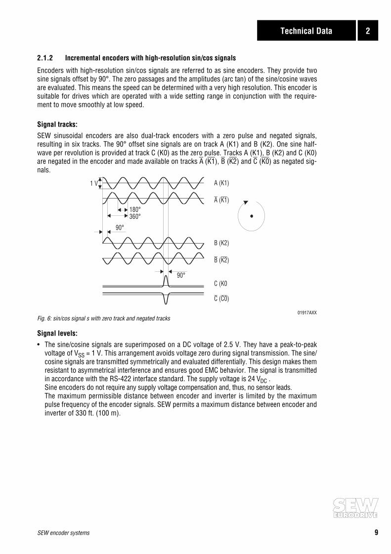
2.1.2 Incremental encoders with high-resolution sin/cos signals
Encoders with high-resolution sin/cos signals are referred to as sine encoders. They provide twosine signals offset by 90°. The zero passages and the amplitudes (arc tan) of the sine/cosine wavesare evaluated. This means the speed can be determined with a very high resolution. This encoder issuitable for drives which are operated with a wide setting range in conjunction with the require-ment to move smoothly at low speed.
Signal tracks:
SEW sinusoidal encoders are also dual-track encoders with a zero pulse and negated signals,resulting in six tracks. The 90° offset sine signals are on track A (K1) and B (K2). One sine half-wave per revolution is provided at track C (K0) as the zero pulse. Tracks A (K1), B (K2) and C (K0)are negated in the encoder and made available on tracks A (K1), B (K2) and C (K0) as negated sig-nals.
01917AXXFig. 6: sin/cos signal s with zero track and negated tracks
Signal levels:
• The sine/cosine signals are superimposed on a DC voltage of 2.5 V. They have a peak-to-peakvoltage of VSS = 1 V. This arrangement avoids voltage zero during signal transmission. The sine/cosine signals are transmitted symmetrically and evaluated differentially. This design makes themresistant to asymmetrical interference and ensures good EMC behavior. The signal is transmittedin accordance with the RS-422 interface standard. The supply voltage is 24 VDC .Sine encoders do not require any supply voltage compensation and, thus, no sensor leads.The maximum permissible distance between encoder and inverter is limited by the maximumpulse frequency of the encoder signals. SEW permits a maximum distance between encoder andinverter of 330 ft. (100 m).
90°
90°
180°360°
A (K1)
A K1( )
B (K2)
B K2( )
C (K0
C C0( )
1 V
10 SEW encoder systems
2 Technical Data
2.1.3 Absolute encoders with MSSI interface
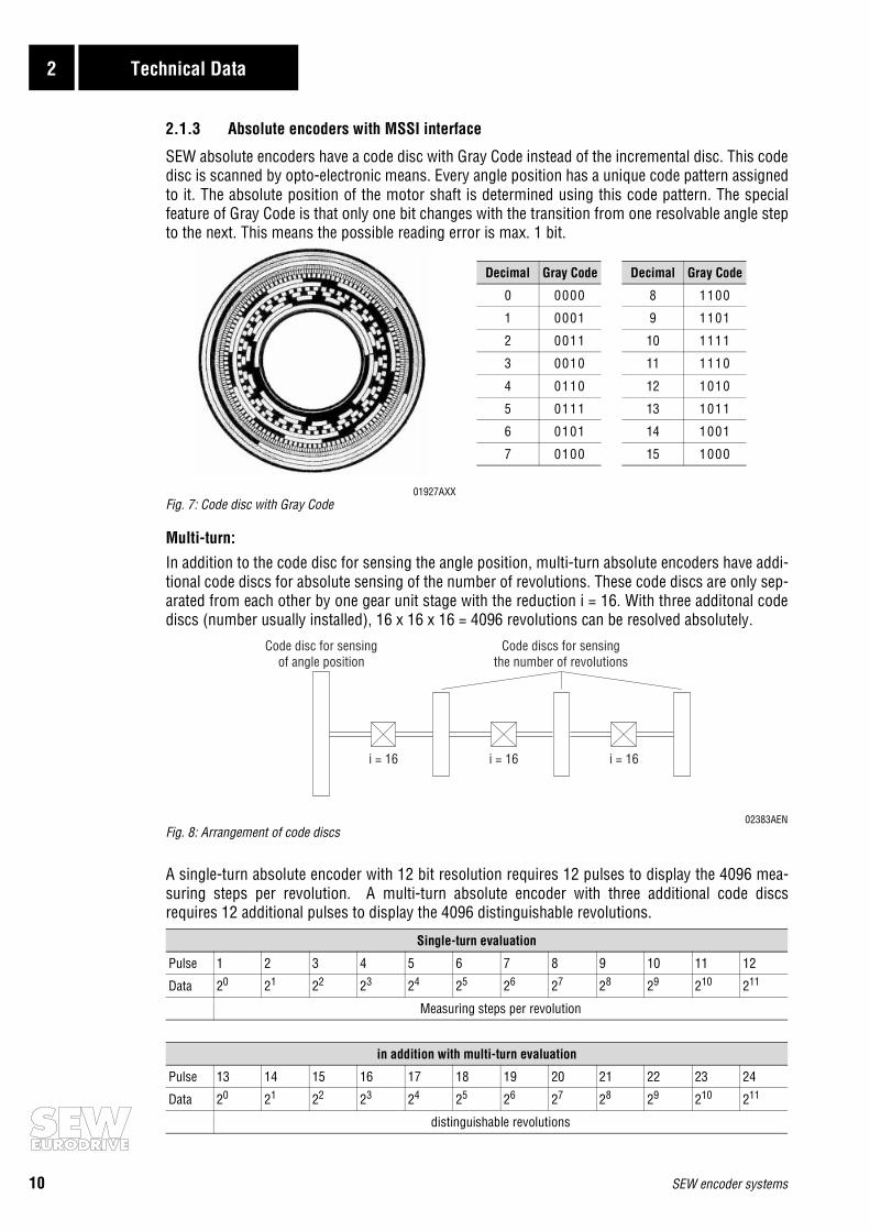
SEW absolute encoders have a code disc with Gray Code instead of the incremental disc. This codedisc is scanned by opto-electronic means. Every angle position has a unique code pattern assignedto it. The absolute position of the motor shaft is determined using this code pattern. The specialfeature of Gray Code is that only one bit changes with the transition from one resolvable angle stepto the next. This means the possible reading error is max. 1 bit.
01927AXXFig. 7: Code disc with Gray Code
Multi-turn:In addition to the code disc for sensing the angle position, multi-turn absolute encoders have addi-tional code discs for absolute sensing of the number of revolutions. These code discs are only sep-arated from each other by one gear unit stage with the reduction i = 16. With three additonal codediscs (number usually installed), 16 x 16 x 16 = 4096 revolutions can be resolved absolutely.
02383AENFig. 8: Arrangement of code discs
A single-turn absolute encoder with 12 bit resolution requires 12 pulses to display the 4096 mea-suring steps per revolution. A multi-turn absolute encoder with three additional code discsrequires 12 additional pulses to display the 4096 distinguishable revolutions.
Single-turn evaluation
Pulse 1 2 3 4 5 6 7 8 9 10 11 12
Data 20 21 22 23 24 25 26 27 28 29 210 211
Measuring steps per revolution
in addition with multi-turn evaluation
Pulse 13 14 15 16 17 18 19 20 21 22 23 24
Data 20 21 22 23 24 25 26 27 28 29 210 211
distinguishable revolutions
i = 16 i = 16 i = 16
Code discs for sensingthe number of revolutions
Code disc for sensingof angle position
Decimal Gray Code Decimal Gray Code
0 0000 8 1100
1 0001 9 1101
2 0011 10 1111
3 0010 11 1110
4 0110 12 1010
5 0111 13 1011
6 0101 14 1001
7 0100 15 1000
SEW encoder systems 11
Technical Data 2
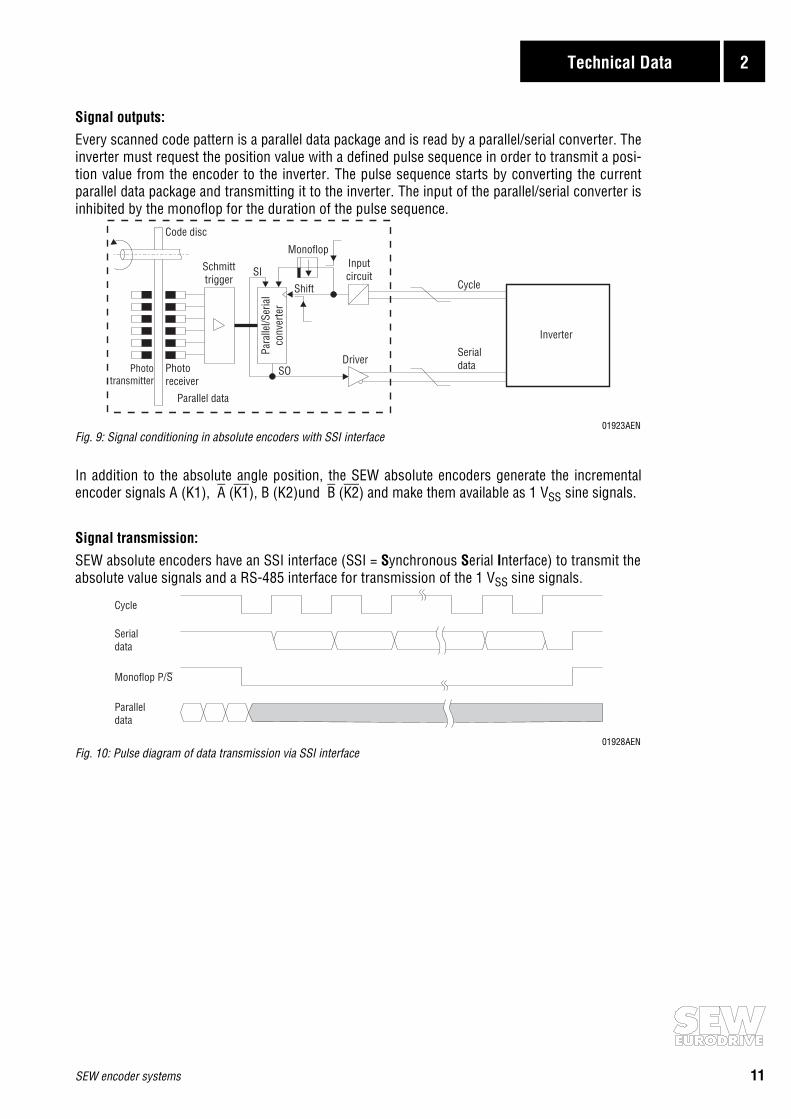
Signal outputs:Every scanned code pattern is a parallel data package and is read by a parallel/serial converter. Theinverter must request the position value with a defined pulse sequence in order to transmit a posi-tion value from the encoder to the inverter. The pulse sequence starts by converting the currentparallel data package and transmitting it to the inverter. The input of the parallel/serial converter isinhibited by the monoflop for the duration of the pulse sequence.
01923AENFig. 9: Signal conditioning in absolute encoders with SSI interface
In addition to the absolute angle position, the SEW absolute encoders generate the incrementalencoder signals A (K1), A (K1), B (K2)und B (K2) and make them available as 1 VSS sine signals.
Signal transmission:SEW absolute encoders have an SSI interface (SSI = Synchronous Serial Interface) to transmit theabsolute value signals and a RS-485 interface for transmission of the 1 VSS sine signals.
01928AENFig. 10: Pulse diagram of data transmission via SSI interface
Inverter
Cycle
Serialdata
Parallel data
Code disc
Driver
Inputcircuit
Schmitttrigger
Para
llel/S
eria
lco
nver
ter
Phototransmitter
Photoreceiver
Monoflop
Shift
SI
SO
Cycle
Serialdata
Monoflop P/S
Paralleldata
12 SEW encoder systems
2 Technical Data
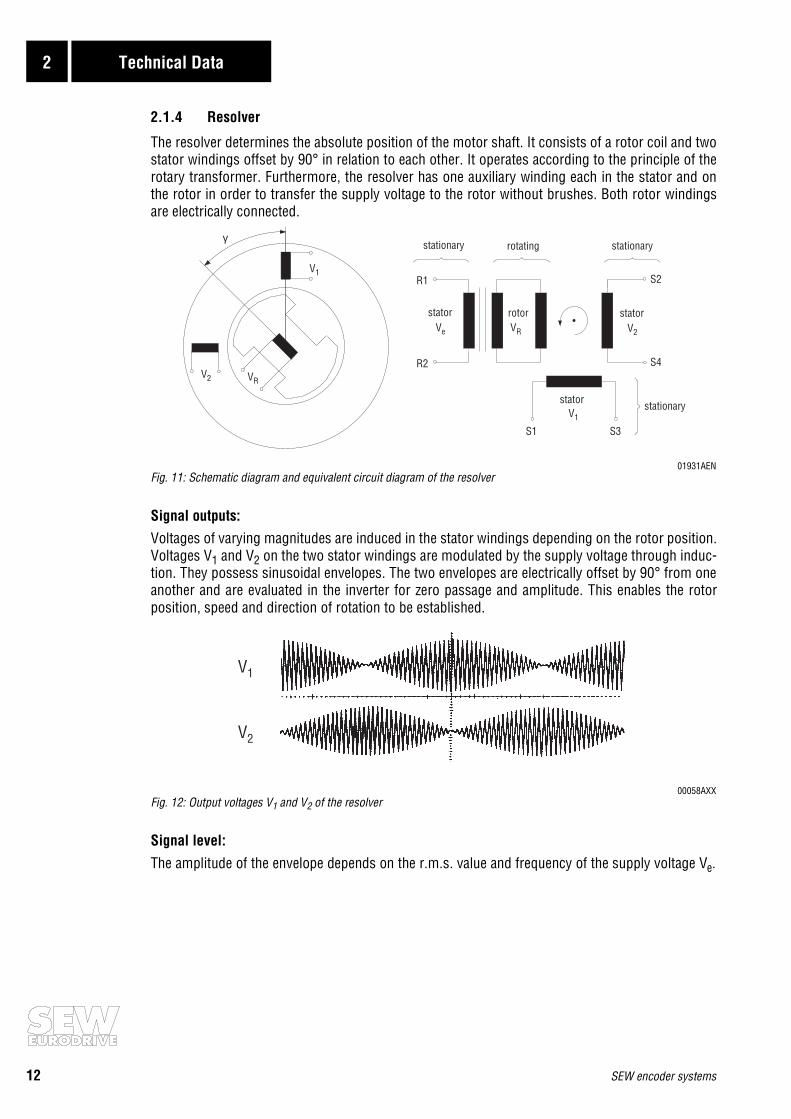
2.1.4 Resolver
The resolver determines the absolute position of the motor shaft. It consists of a rotor coil and twostator windings offset by 90° in relation to each other. It operates according to the principle of therotary transformer. Furthermore, the resolver has one auxiliary winding each in the stator and onthe rotor in order to transfer the supply voltage to the rotor without brushes. Both rotor windingsare electrically connected.
01931AENFig. 11: Schematic diagram and equivalent circuit diagram of the resolver
Signal outputs:Voltages of varying magnitudes are induced in the stator windings depending on the rotor position.Voltages V1 and V2 on the two stator windings are modulated by the supply voltage through induc-tion. They possess sinusoidal envelopes. The two envelopes are electrically offset by 90° from oneanother and are evaluated in the inverter for zero passage and amplitude. This enables the rotorposition, speed and direction of rotation to be established.
00058AXXFig. 12: Output voltages V1 and V2 of the resolver
Signal level:
The amplitude of the envelope depends on the r.m.s. value and frequency of the supply voltage Ve.
γ
S1 S3
S4
S2R1
R2
V1
stator statorrotorV2VRVe
stator stationary
rotating stationarystationary
V2 VR
V1
V1
V2

SEW encoder systems 13
Technical Data 2
2.1.5 Proximity sensors
Proximity sensors represent a simple and inexpensive means of monitoring whether the motor isturning. By using a two-track proximity sensor, it is also possible to determine the direction inwhich the motor is rotating. Proximity sensors are mounted on the side of the fan guard, and thusdo not add to the length of the motor.
Signal outputs:
Proximity sensors react to the attenuation lugs on the fan. The number of attenuation lugs deter-mines the number of pulses per revolution.
01929AXXFig. 13: Setup of the proximity sensor system
The proximity sensors are constructed with HTL technology and have an NO contact output whichis actuated every time there is a pulse. This NO contact output switches the connected supply volt-age. Proximity sensors have a mark-to-space ratio of 1:1.
01930AENFig. 14: Signal output of the proximity sensors
Signal level:
The signal level is determined by the supply voltage, usually 24 VDC.
90°A
B
PNP
PNP
VB
VB
additional with two-track proximity sensor

14 SEW encoder systems
2 Technical Data
2.2 Incremental encoders
2.2.1 Incremental encoders with spread shaft
01934AXXFig. 15: SEW encoder with spread shaft
* recommended encoder for operation with MOVITRAC® 31C** recommended encoder for operation with MOVIDRIVE®
Encoder type for asynchronous AC motors 71...100 ES1T* ES1S** ES1R ES1C
Encoder type for asynchronous AC motors 112...132S ES2T* ES2S** ES2R ES2C
Supply voltage VB 5 VDC ±5 % 24 VDC ±20 %
Max. current consumption Iin 180 mARMS 160 mARMS 180 mARMS 340 mARMS
Max. pulse frequency fmax 120 kHz
Pulses (sine periods) per A, Brevolution C
10241
Output amplitude per track VhighVlow
≥ 2.5 VDC≤ 0.5 VDC
1 VSS≥ 2.5 VDC≤ 0.5 VDC
≥ VB minus 3.5 VDC≤ 1.5 VDC
Signal output 5 V TTL sin/cos 5 V TTL HTL
Output current per track Iout 20 mARMS 40 mARMS 20 mARMS 60 mARMS
Mark-to-space ratio 1 : 1 ±20 %
Phase angle A : B 90° ±20 %
Ambient temperature ϑamb -25 °C...+60 °C (EN 60721-3-3, class 3K3)
Enclosure IP56 (EN 60529)
Connection Terminal box on encoder

SEW encoder systems 15
Technical Data 2
2.2.2 Incremental encoders with solid shaft
01935AXXFig. 16: SEW encoder with solid shaft
* recommended encoder for operation with MOVITRAC® 31C** recommended encoder for operation with MOVIDRIVE®
Encoder type EV1T* EV1S** EV1R EV1C
For motors asynchronous AC motors DT/DV/D 71...225
Supply voltage VB 5 VDC ±5 % 24 VDC ±20 %
Max. current consumption Iin 180 mARMS 160 mARMS 180 mARMS 340 mARMS
Max. pulse frequency fmax 120 kHz
Pulses (sine periods) per A, Brevolution C
10241
Output amplitude per track VhighVlow
≥ 2.5 VDC≤ 0.5 VDC
1 VSS≥ 2.5 VDC≤ 0.5 VDC
≥ VB minus 3.5 VDC≤ 1.5 VDC
Signal output 5 V TTL sin/cos 5 V TTL HTL
Output current per track Iout 20 mARMS 40 mARMS 20 mARMS 60 mARMS
Mark-to-space ratio 1 : 1 ±20 %
Phase angle A : B 90° ±20 %
Ambient temperature ϑamb -25 °C...+60 °C (EN 60721-3-3, class 3K3)
Enclosure IP56 (EN 60529)
Connection Terminal box on encoder
16 SEW encoder systems
2 Technical Data
2.3 Absolute encoder
01933BXXFig. 17: SEW absolute encoder
Encoder type AGY
For motorssynchronous servomotors DS56, DY71...112
asynchronous servomotors CT/CV71...180asynchronous AC motorsDT/DV71...225
Supply voltage VB 10 – 15 – 24 – 30 VDC protected against polarity reversal
Max. current consumption Iin 250 mA
Max. stepping frequency fmax ≥ 100 kHz
Pulses (sine periods) per revolutionA,B 512
Output amplitude per track 1 VSS sin/cos
Sensing code Gray Code
Single-turn resolution 4096 steps/revolution (12 bits)
Multi-turn resolution 4096 revolutions (12 bits)
Data transfer, absolute values Synchronous, serial (SSI)
Serial data output Driver to EIA RS-485
Serial pulse input Opto-coupler, recommended driver to EIA RS-485
Switching frequency Permitted range: 90 – 300 – 1100 kHz(max. 330 ft./100 m cable length with 300 kHz)
Monoflop time 12 – 35 µs
Vibration (55...2000 Hz) ≤ 100 m/s2 (DIN IEC 68-2-6)
Maximum speed nmax 6000 rpm
Mass m 0.30 kg
Operating temperature ϑamb -15 °C...+60 °C (EN 60721-3-3, class 3K3)
Enclosure IP65 (EN 60529)
Connection 3.3 ft/1 m cable with 17-pin round connector plugfor socket plug SPUC 17B FRAN

SEW encoder systems 17
Technical Data 2
2.4 Resolver
MD0116AXFig. 18: SEW resolver
Encoder type RH1M
For motorssynchronous servomotors
DS56 DY71 DY90 DY112
Supply voltage V12 7 VAC_eff / 7 kHz
Max. current consumption I12 70 mA 60 mA 30 mA
Number of poles 2
Ratio r 0.5 0.45 0.46
Output impedance ZSS 200...330 Ω 130...270 Ω 350...500 Ω
Operating temperature ϑB -55 °C...+125 °C
Connection Terminal box (10-pin Phoenix terminal strip) or plug connector, depending on motor type
Plug connector DS56: Intercontec, type ASTA021NN00 10 000 5 000Plug connector DY71...112: Framatone Souriou, type GN-DMS2-12S

18 SEW encoder systems
2 Technical Data
2.5 Proximity sensors
01932AXXFig. 19: SEW proximity sensors
Encoder type NV16 NV26
For motors/brake motors asynchronous AC motors 71(BMG)...132S(BMG)
Supply voltage VB 10 – 24 – 65 VDC
Max. operating current Imax 200 mA
Max. pulse frequency fmax 1.5 kHz
Pulses/revolution 6A track
6A+B track
Output NO contact (pnp)
Mark-to-space ratio 1 : 1 ±20 %
Phase angle A : B - 90° ±45 % (typical at 20 °C)
Ambient temperature ϑamb 0 °C...+60 °C (EN 60721-3-3, class 3K3)
Enclosure IP67 (EN 60529)
Connection M12 × 1 connector, e.g. RKWT4 (Lumberg)

SEW encoder systems 19
Technical Data 2
2.6 Mounting devices
01949AXXFig. 20: Mounting device for non-SEW encoders
See section 3.6.2, page 31 (ES1A, ES2A, EV1A) and section 3.6.4, page 36 (AV1A) regardingdimensions and extended motor lengths for encoder mounting devices.
Mounting device ES1A ES2A
For motors asynchronous AC motors 71...100 asynchronous AC motors 100...132S
For encoder Spread shaft encoder with8 mm center bore
Spread shaft encoder with10 mm center bore
Mounting device EV1A AV1A
For motors asynchronous AC motors DT71...DV225
synchronous servomotors DS56, DY71...112
For encoder Solid shaft encoder (synchro flange)
Diameter of flange 58 mm
Diameter of center hole 50 mm
Diameter of shaft end 6 mm
Length of shaft end 10 mm
Mounting 3 pcs. encoder mounting clamps (bolts with eccentric discs)for 3 mm flange thickness

20 SEW encoder systems
3 Installation
3 Installation
3.1 General information
Always follow the operating instructions for the relevant inverter when connecting the encoderto the SEW inverters!
• Max. line length (inverter – encoder):330 ft (100 m) with a cable capacitance per unit length ≤ 120 nF/km (193 nF/mile)
• Core cross section: 0.25 – 0.5 mm2 (AWG24 – AWG20)• Use a shielded cable with twisted pairs of cores (exception: HTL encoder cable) and connect the
shield at both ends:- on the encoder in the PG fitting or in the encoder plug- on the inverter to the electronics shield clamp or to the housing of the Sub D connector
• Route the encoder cable separately from the power cables.
Connect the shield of the encoder cable over a large surface area:
• on the inverter
01937AXXFig. 21: Connect the shield to the electronics shield clamp of the inverter
01939BXXFig. 22: Connect the shield in the Sub D connector
• on the encoder
01948AXXFig. 23: Connect the shield to the PG fitting of the encoder

SEW encoder systems 21
Installation 3
3.2 Incremental encoders
01936AXXFig. 24: Connecting terminals of the SEW encoder
3.2.1 Encoders for MOVITRAC® 31C frequency inverters
SEW recommends the 5 V TTL encoders ES1T, ES2T or EV1T for operation with the MOVITRAC®
31C frequency inverter. The sensor leads have to be connected in order to compensate the encodersupply voltage. Connect the encoder as follows:
* Connect the sensor leads on the encoder to UB and ⊥, do not jumper them on the encoder!01585BXX
Fig. 25: Connection of TTL encoders ES1T, ES2T or EV1T to MOVITRAC® 31C
Channels K0 (C) and K0 (C) are only required for position control (FPI31C option). Channels K0 (C)and K0 (C) are not required for speed control (FRN31C or FEN31C option) and synchronous opera-tion (FRS31C option).
A (K1)( )
B (K2)( )
C (K0)( )
UB
A K1
B K2
C K0
⊥
ES1T / ES2T / EV1T
UB K1 K2 K0⊥ K1 K2 K0UB A B C⊥ A B C
max. 100 m (330 ft)
8889909192939495*96*97
MC31CFEN 31C/FPI 31C
y y
X6:

22 SEW encoder systems
3 Installation
3.2.2 Encoders for MOVIDRIVE® MDV60A drive inverters The core colors indicated in the wiring diagrams according to color code meeting IEC757 corre-spond to the core colors of the pre-fabricated cables by SEW (→ section 3.7).
24 V sin/cos encoders ES1S, ES2S or EV1S
SEW recommends the high-resolution 24 V sin/cos encoders ES1S, ES2S or EV1S for operationwith the MOVIDRIVE® drive inverter. 24 V encoders do not require sensor leads. Connect theencoder as follows:
01381BXXFig. 26: Connection of sin/cos encoder ES1S, ES2S or EV1S to MOVIDRIVE®
24 V TTL encoders ES1R, ES2R or EV1R
It is also possible to connect TTL encoders with 24 VDC encoder supply ES1R, ES2R, EV1R directlyto MOVIDRIVE® MDV60A. Install the TTL encoders in exactly the same way as the high-resolutionsin/cos encoders (→ Fig. 26).
HTL encoders ES1C, ES2C or EV1CIf you are using an HTL encoder ES1C, ES2C or EV1C, you must not connect the negated channelsA (K1), B (K2) and C (K0) to MOVIDRIVE® !
02558AXXFig. 27: Connection of HTL encoder ES1C, ES2C or EV1C to MOVIDRIVE®
162738954
YEGNRDBUPKGYWHBNVT
1
5
6
9
X15:max. 100 m (330 ft)
A (K1)( )
B (K2)( )
C (K0)( )
UB
A K1
B K2
C K0
⊥
ES1S / ES2S / EV1SES1R / ES2R / EV1R
UB K1 K2 K0⊥ K1 K2 K0
y y
UB A B C⊥ A B C
1N.C. 6
2N.C. 7
3N.C. 8
95
N.C. 4
YE
RD
PK
WHBN
1
5
6
9
X15:max. 100 m (330 ft)
A (K1)( )
B (K2)( )
C (K0)( )
UB
A K1
B K2
C K0
⊥
ES1C / ES2C / EV1C
UB K1 K2 K0⊥ K1 K2 K0
y y
UB A B C⊥ A B C
SEW encoder systems 23
Installation 3
5V TTL encoders ES1T, ES2T or EV1TUse the “5 V encoder supply type DWI11A” MOVIDRIVE® option (part number 822 759 4) if youhave to connect an encoder with a 5 VDC encoder supply ES1T, ES2T or EV1T to MOVIDRIVE® . Thesensor leads have to be connected in order to compensate the supply voltage. Connect the encoderas follows:
* Connect the sensor lead on the encoder to UB, do not jumper on the DWI11A!01377BXX
Fig. 28: Connection of TTL encoder ES1T, ES2T or EV1T to MOVIDRIVE®
1
5
5
1
6
9
9
6
DWI11A
X2: E
ncod
erX1
: MOV
IDRI
VE
max. 5 m (16.5 ft)
max. 100 m (330 ft)
1
5
6
9
X15:
ES1T / ES2T / EV1T162738954*
y y
YEGNRDBUPKGYWHBNVT*
162738954
A (K1)( )
B (K2)( )
C (K0)( )
UB
A K1
B K2
C K0
⊥
A (K1)( )
B (K2)( )
C (K0)( )
UB
N.C.
A K1
B K2
C K0
⊥
162738954
y y
YEGNRDBUPKGYWHBNVT
UB K1 K2 K0⊥ K1 K2 K0UB A B C⊥ A B C
814 344 7
198 829 8198 828 X
24 SEW encoder systems
3 Installation
3.3 AV1Y absolute encoder
The AV1Y absolute encoder has a permanently installed connector that is one meter long (3.3 ft.)with a 17-pin round connector plug fitting socket plug SPUC 17B FRAN by Interconnectron. Theplug connection has the following pin assignment:
AV1Y is connected to:
• MOVIDYN® MAS/MKS51A servo controller with option “APA12 single axis positioning control”• MOVIDRIVE® MDS60A drive inverter with option “DPA11A single axis positioning control”
• MOVIDRIVE® MDS/MDV60A drive inverter with option “DIP11A absolute encoder card”
Synchronous servomotors are speed-controlled with the resolver signals. Therefore, the incremen-tal encoder signals A, A, B and B are not evaluated by MOVIDYN® MAS/MK51A or MOVIDRIVE®
MDS60A. The AV1Y connectors 12, 13, 15 and 16 will not be assigned in this instance. MOVID-RIVE® MDV60A uses the incremental encoder signals A, A, B and B for speed control of asynchro-nous motors. The AV1Y connectors 12, 13, 15 and 16 will be directed to X15: “ENCODER IN“ ofthe MOVIDRIVE® MDV60A.
The core colors in the wiring diagrams according to color code meeting IEC757 correspond to thecore colors in the pre-fabricated SEW cables (→ section 3.7).
3.3.1 Absolute encoder with MOVIDYN® MAS/MKS51A servo controller
The AV1Y absolute encoder is connected to the APA12 option:
01940BXXFig. 29: Connection to MOVIDYN® MAS/MKS51A servo controller with APA12
Pin DescriptionCore color of pre-fabricated cable
6-core cable 10-core cable
7 Supply voltage VS+13 – 15 – 24 VDC, protected against
polarity reversal white (WH) white (WH)
10 Supply voltage GND Electrically isolated from the AGY housing brown (BN) brown (BN)
14 Serial data output D+ “1” = High signal yellow (YE) black (BK)
17 Serial data output D- “0” = High signal green (GN) violet (VT)
8 Clock line, current loop T+ 7 mA towards T+ = “1” pink (PK) pink (PK)
9 Clock line, current loop T- 7 mA towards T- = “0” grey (GY) grey (GY)
15 Incremental encoder - signal A 1 Vss sin/cos - yellow (YE)
16 Incremental encoder - signal A 1 Vss sin/cos - green (GN)
12 Incremental encoder - signal B 1 Vss sin/cos - red (RD)
13 Incremental encoder - signal B 1 Vss sin/cos - blue (BU)
3
45 6
9
1011
1213
14 15
1617
12
7
8
891417107
PKGYYEGNBNWH
T+T-
D+D-
GNDUS
max. 100 m (330 ft)
323334353839
APA12X11:
y y
AV1Y

SEW encoder systems 25
Installation 3
3.3.2 Connection of absolute encoder to MOVIDRIVE® MDS60A drive inverterThe AV1Y absolute encoder is connected to the DPA11A option:
01941BXXFig. 30: Connection to MOVIDRIVE® MDS60A drive inverter with DPA11A
The AV1Y absolute encoder is connected to the DIP11A option:
01942BXXFig. 31: Connection to MOVIDRIVE® MDS60A drive inverter with DIP11A
3.3.3 Absolute encoder with MOVIDRIVE® MDV60A drive inverterThe AV1Y absolute encoder is connected to the DIP11A option and to X15:
02544AXXFig. 32: Connection to MOVIDRIVE® MDV60A drive inverter with DIP11A
T+T-
D+D-
GNDUS
max. 100 m (330 ft)
323334353839
DPA11AX50:
yy
3
45 6
9
1011
1213
14 15
1617
12
7
8
891417107
AV1YPKGYYEGNBNWH
T+T-
D+D-
GNDUS
max. 100 m (330 ft)
y
381659
(N.C.) 2(N.C.) 4(N.C.) 7
1
5
6
9
DIP11AX62:
y
3
45 6
9
1011
1213
14 15
1617
12
7
8
891417107
AV1YPKGYYEGNBNWH
T+T-
D+D-
GNDU
A (K1)( )
B (K2)( )
S
A K1
B K2
max. 100 m (330 ft)
y
y
381659
(N.C.) 2(N.C.) 4(N.C.) 7
1627
(N.C.) 3(N.C.) 4(N.C.) 5(N.C.) 8(N.C.) 9
1
5
6
9
1
5
6
9
DIP11AX62:
MOVIDRIVEX15:
®
y
3
45 6
9
1011
1213
14 15
1617
12
7
8
89141710715161213
AV1YPKGYBKVTBNWHYEGNRDBU
26 SEW encoder systems
3 Installation
3.4 Resolver
Resolvers are installed into SEW synchronous motors as standard feature. The inverter uses theresolver signals to control the motor speed. The resolver connections are located in the terminalbox on a 10-pin Phoenix terminal strip or in the plug connection, depending on the motor type. Plug connector DS56: Intercontec, type ASTA021NN00 10 000 5 000Plug connector DY71...112:: Framatone Souriou, type GN-DMS2-12S
The resolver signals have the same numbers on the 10-pin Phoenix terminal strip and in the plugconnectors.
The resolver is connected to:
• MOVIDYN® MAS/MKS51A servo controller
• MOVIDRIVE® MDS60A drive inverterThe core colors in the wiring diagrams according to color code meeting IEC757 correspond to thecore colors in the pre-fabricated SEW cables (→ section 3.7).
3.4.1 Resolver with MOVIDYN® MAS/MKS51A servo controller
Connect the resolver as follows:
01952AEN1) Plug connector2) Terminal stripFig. 33: Connection to MOVIDYN® servo controller
Terminal/pin Description Core color in pre-fabricated cable
1 Ref.+Reference
Pink (PK)
2 Ref.- Gray (GY)
3 cos+Cosine signal
Red (RD)
4 cos- Blue (BU)
5 sin+Sine signal
Yellow (YE)
6 sin- Green (GN)
9 TF/THMotor protection
White (WH)
10 TF/TH Brown (BN)
Ref.+Ref.-cos+cos-sin+sin-N.C.N.C.
TF/THTF/TH
12345678910
max. 100 m (330 ft)
34 5
6
9
10
11
12
1
2 7
8
123456
MAS51A/MKS51AX31:
DFS56DFY71...112 PK
GYRDBUYEGN
WHBN
1)
2) y y
Thermalshut off

SEW encoder systems 27
Installation 3
3.4.2 Resolver with MOVIDRIVE® MDS60A drive inverterConnect the resolver as follows:
01414AXX1) Plug connector2) Terminal stripFig. 34: Connection to MOVIDRIVE® MDS drive inverter
Ref.+Ref.-cos+cos-sin+sin-N.C.N.C.
TF/THTF/TH
12345678910
1
5
6
9
382716954
PKGYRDBUYEGN
WHBNVT
X15:max. 100 m (330 ft)
34 5
6
9
10
11
12
1
2 7
8
DFS56DFY71...112
y y
1)
2)
28 SEW encoder systems
3 Installation
3.5 Proximity sensors
Assembly:
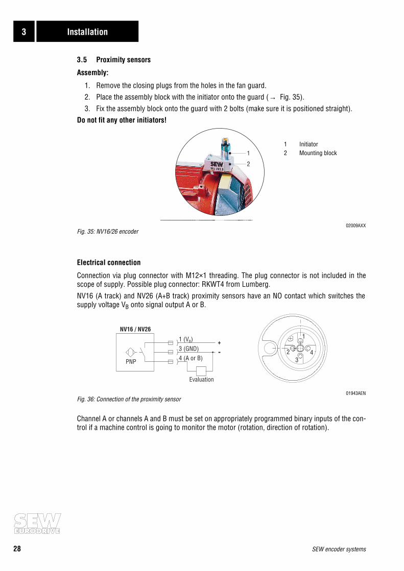
1. Remove the closing plugs from the holes in the fan guard.
2. Place the assembly block with the initiator onto the guard (→ Fig. 35).
3. Fix the assembly block onto the guard with 2 bolts (make sure it is positioned straight).Do not fit any other initiators!
02009AXXFig. 35: NV16/26 encoder
Electrical connection
Connection via plug connector with M12×1 threading. The plug connector is not included in thescope of supply. Possible plug connector: RKWT4 from Lumberg.
NV16 (A track) and NV26 (A+B track) proximity sensors have an NO contact which switches thesupply voltage VB onto signal output A or B.
01943AENFig. 36: Connection of the proximity sensor
Channel A or channels A and B must be set on appropriately programmed binary inputs of the con-trol if a machine control is going to monitor the motor (rotation, direction of rotation).
1
2
3PNP
1
2 4
NV16 / NV26
+
-
Evaluation
1 (V )B
3 (GND)4 (A or B)
1 Initiator2 Mounting block
SEW encoder systems 29
Installation 3
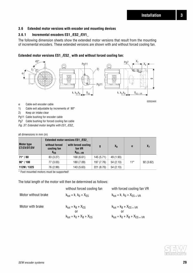
3.6 Extended motor versions with encoder and mounting devices
3.6.1 Incremental encoders ES1_/ES2_/EV1_
The following dimension sheets show the extended motor versions that result from the mountingof incremental encoders. These extended versions are shown with and without forced cooling fan.
Extended motor versions ES1_/ES2_ with and without forced cooling fan:
02552AXXα Cable exit encoder cable1) Cable exit adjustable by increments of 90°2) Keep air intake clearPg11 Cable bushing for encoder cablePg7 Cable bushing for forced cooling fan cableFig. 37: Extended motor lengths with ES1_/ES2_
all dimensions in mm (in)
* Foot mounted motors must be supported!
The total length of the motor will then be determined as follows:
Motor typeCT/CV/DT/DV
Extended motor versions ES1_/ES2_
g X8 α X7without forced
cooling fanXES
with forced cooling fan VRXES + VR
71* / 80 83 (3.27) 168 (6.61) 145 (5.71) 49 (1.93)
11° 92 (3.62)90* / 100 77 (3.03) 180 (7.09) 197 (7.76) 54 (2.13)
112M / 132S 76 (2.99) 143 (5.63) 221 (8.70) 54 (2.13)
without forced cooling fan with forced cooling fan VR
Motor without brake ktot = k, k0 + XES ktot = k, k0 + XES + VR
Motor with brake ktot = kB + XESor
ktot = k0 + XB + XES
ktot = kB + XES + VRor
ktot = k0 + XB + XES + VR
α
45°
1)
XES
2)
Pg11
Pg11
XES + VR
g
X7X8
Pg7
k, k ,k0 B k, k ,k0 B

30 SEW encoder systems
3 Installation
Extended motor versions EV1_ with and without forced cooling fans VR, VS, V:
02553AXX1) Keep air intake clearPg11 Cable bushing for encoder cableFig. 38: Extended motor versions with EV1_
all dimensions in mm (in)
* Foot mounted versions have to be supported!
The total length of the motor will then be calculated as follows:without forced cooling fan ktot = k, k0 + XEV
with forced cooling fan VR ktot = k, k0 + XEV + VR
with forced cooling fan VS ktot = k, k0 + XEV + VS
with forced cooling fan V ktot = k, k0 + XEV + V
Motor typeCT/CV/DT/DV
Extended motor versions EV1_
gwithout forced cooling fan
XEV
with forced cooling fan VRXEV + VR
with forced cooling fan VSXEV + VS
with forced cooling fan V
XEV + V
71* / 80 193 (7.60) 265 (10.43) 293 (11.54) - 150 (5.91)
90* / 100 196 (7.72) 307 (12.09) 332 (13.07) - 201 (7.91)
112 / 132S 191 (7.52) 273 (10.75) 342 (13.46) - 226 (8.90)
132M* / 160M 224 (8.82) - - 429 (16.89) 285 (11.22)
160L* / 180 265 (10.43) - - 405 (15.94) 342 (13.46)
200 / 225 265 (10.43) - - 415 (16.34) 394 (15.51)
k, k0 XEV
XEV + VS, V
k, k0 XEV
XEV + VR
1)1)
gg
Pg11Pg11
VS, VVR
SEW encoder systems 31
Installation 3
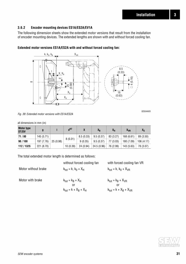
3.6.2 Encoder mounting devices ES1A/ES2A/EV1AThe following dimension sheets show the extended motor versions that result from the installationof encoder mounting devices. The extended lengths are shown with and without forced cooling fan.
Extended motor versions ES1A/ES2A with and without forced cooling fan:
02554AXXFig. 39: Extended motor versions with ES1A/ES2A
all dimensions in mm (in)
The total extended motor length is determined as follows:
Motor typeDT/DV g l dH7 X XB XH XVR XS
71 / 80 145 (5.71)
25 (0.98)8 (0.31)
8.5 (0.33) 9.5 (0.37) 83 (3.27) 168 (6.61) 89 (3.50)
90 / 100 197 (7.76) 9 (0.35) 9.5 (0.37) 77 (3.03) 180 (7.09) 106 (4.17)
112 / 132S 221 (8.70) 10 (0.39) 24 (0.94) 24.5 (0.96) 76 (2.99) 143 (5.63) 78 (3.07)
without forced cooling fan with forced cooling fan VR
Motor without brake ktot = k, k0 + XH ktot = k, k0 + XVR
Motor with brake ktot = kB + XH or
ktot = k + XB + XH
ktot = kB + XVR or
ktot = k + XB + XVR
k, k , k0 B XVR
g
XS
XH
lX, XB
d
25(0
.98)
8.5(0.33)
16(0.63)
∅4
(0.1
6)
32 SEW encoder systems
3 Installation
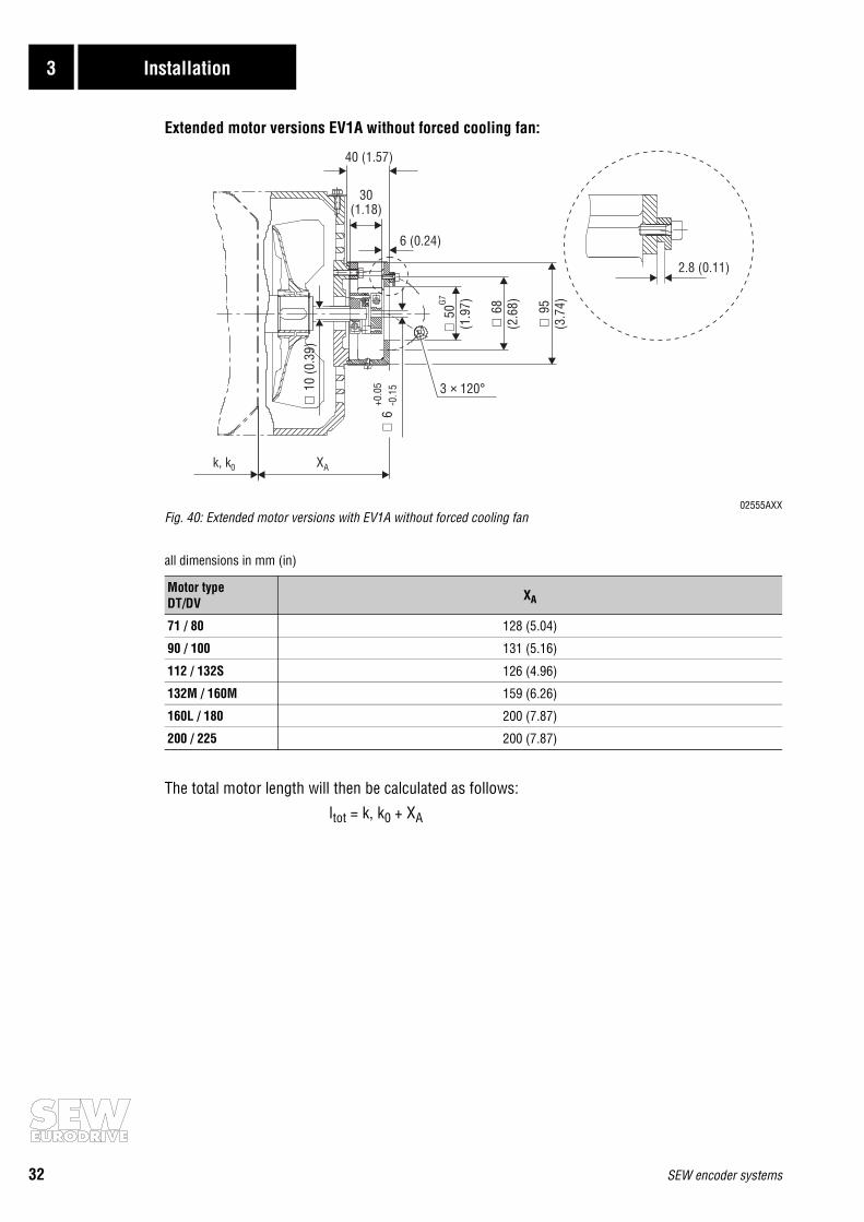
Extended motor versions EV1A without forced cooling fan:
02555AXXFig. 40: Extended motor versions with EV1A without forced cooling fan
all dimensions in mm (in)
The total motor length will then be calculated as follows:
ltot = k, k0 + XA
Motor typeDT/DV XA
71 / 80 128 (5.04)
90 / 100 131 (5.16)
112 / 132S 126 (4.96)
132M / 160M 159 (6.26)
160L / 180 200 (7.87)
200 / 225 200 (7.87)
40 (1.57)
k, k0 XA
2.8 (0.11)
∅10
(0.3
9)
3 120°×∅
6+0
.05
-0.1
5
6 (0.24)
30(1.18)
∅ ∅ ∅
50(1
.97) 68
(2.6
8) 95(3
.74)G7

SEW encoder systems 33
Installation 3
Extended motor versions with forced cooling fan VR and EV1A (→ Fig. 40, page 32):
02556AXXFig. 41: Extended motor versions with forced cooling fan VR and EV1A
all dimensions in mm (in)
The total motor length will then be calculated as follows: ltot = k, k0 + XVR
Extended motor versions forced cooling fans VS, V with EV1A (→ Fig. 40, page 32):
02557AXXFig. 42: Extended motor versions with forced cooling fans VS, V and EV1A
all dimensions in mm (in)
The total motor length will then be calculated as follows: ltot = k, k0 + XVS, V
Motor typeDT/DV XA XS/VR XVR g
71 / 80 128 (5.04) 94 (3.70) 290 (11.42) 150 (5.91)
90 / 100 131 (5.16) 105 (4.13) 307 (12.09) 201 (7.91)
112 / 132S 126 (4.96) 82 (3.23) 273 (10.75) 226 (8.90)
Motor typeDT/DV XA XS / VS, V XVS XV g
71 / 80 128 (5.04) 80 (3.15) 293 (11.54) - 150 (5.91)
90 / 100 131 (5.16) 114 (4.49) 332 (13.07) - 201 (7.91)
112 / 132S 126 (4.96) 121 (4.76) 337 (13.27) - 226 (8.90)
132M / 160M 159 (6.26) 70 (2.76) - 339 (13.35) 285 (11.22)
160L / 180 200 (7.87) 71 (2.80) - 405 (15.94) 342 (13.46)
200 / 225 200 (7.87) 70 (2.76) - 415 (16.34) 394 (15.51)
XA XS/VR
k, k0 XVR
g
k, k0 XVS, V
XA XS / VS, V
g

34 SEW encoder systems
3 Installation
3.6.3 Absolute encoder AV1YThe following dimension sheets show the extended motor versions resulting from the installationof the AV1Y absolute encoder. The extended versions are shown with and without forced coolingfan.
Extended motor versions AV1Y with and without forced cooling fans VR, VS, V on CT/CV/DT/DVmotors:
02559AXX1) Keep air intake clearFig. 43: Extended motor versions CT/CV/DT/DV with AV1Y
all dimensions in mm (in)
* Foot mounted motors must be supported!
The total motor length will then be calculated as follows:without forced cooling fan ktot = k, k0 + XAV1Y
with forced cooling fan VR ktot = k, k0 + XAV1Y+VR
with forced cooling fan VS ktot = k, k0 + XAV1Y+VS
with forced cooling fan V ktot = k, k0 + XAV1Y+V
Motor typeCT/CV/DT/DV
Extended motor versions AV1Y
gwithout forced cooling fan
XAV1Y
with forced cooling fan VR
XAV1Y + VR
with forced cooling fan VS
XAV1Y + VS
with forced cooling fan V
XAV1Y + V
71* / 80 187 (7.36) 290 (11.42) 293 (11.54) - 150 (5.91)
90* / 100 191 (7.52) 307 (12.09) 332 (13.07) - 201 (7.91)
112 / 132S 185 (7.28) 273 (10.75) 337 (13.27) - 226 (8.90)
132M* / 160M 218 (8.58) - - 339 (13.35) 285 (11.22)
160L* / 180 259 (10.20) - - 405 (15.94) 342 (13.46)
200 / 225 259 (10.20) - - 415 (16.34) 394 (15.51)
k, k0 XAV1Y
XAV1Y + VS, V
k, k0 XAV1Y
XAV1Y + VR
1)1)
gg1 m(3.3 ft)
1 m(3.3 ft)
VR VS / V

SEW encoder systems 35
Installation 3
Extended motor versions AV1Y at DS/DY motors:without brake with brake
02560AXX1) Brake connectionThe dimension k0 depends on the motor version, please observe the respective dimension sheet. Fig. 44: Extended motor versions DS/DY with AV1Y
all dimensions in mm (in)
Motor type k5 k6 k7 g3 g4B g5 g6
DS56 96 (3.78) -
59 (2.32)
73 (2.87) - -
58 (2.28)DY71 126 (4.96) 27 (1.06) 118 (4.65) 101 (3.98) 16 (0.63)
DY90 133 (5.24) 31 (1.22) 142 (5.59) 96 (3.78) 20 (0.79)
DY112 133 (5.24) 30 (1.18) 186 (7.32) 111 (4.37) 20 (0.79)
1 m(3.3 ft)
1)
1 m(3.3 ft)
k0 k5
k7
g 6 g 3
g5
k0 k5
k7
k6
g 4B
g 6 g 3

36 SEW encoder systems
3 Installation
3.6.4 Encoder mounting devices AV1AThe following dimension sheet shows the extended motor versions resulting from the installationof encoder mounting devices.
Extended motor versions AV1A on DS/DY motors:
02632AXX1) Plugs with brake motorsFig. 45: Extended motor versions DS/DY with AV1A
all measurements in mm (in)
Motor type b d e k6 s2 α β χ M
DS56
50 (1.97) 6 (0.24) 68 (2.68)
36 (1.42) 5 (0.20) -15° 120° -15°
M4DY71 61 (2.40)
5.5 (0.22)
30° 120° 20°
DY9069 (2.72) 0° 3×120° -
DY112
1)
α
βχ
M
e
k6
s2
∅bG7
∅d

SEW encoder systems 37
Installation 3
3.7 Pre-fabricated cables
SEW offers pre-fabricated cables for a convenient and secure connection of encoder systems toasynchronous AC motors and synchronous servomotors. It is necessary to differentiate betweencables intended for fixed or trailing-cable installations. The cables are pre-fabricated in 40 inch (1 m) steps to the required length.
02547AXXFig. 46: Pre-fabricated cable for encoder connection and incremental encoders
02548AXXFig. 47: Pre-fabricated cables for absolute encoders
MOVIDRIVEMDV60A
®
X2:E
ncod
erX1
:MOV
IDRI
VE
DWI
2
1
MOVIDRIVEMDV60A
®
2 3+
ES1T, ES2T, EV1T
DWI11A
ES1S, ES2S, EV1S,ES1R, ES2R, EV1R
ES1C,ES2C,EV1C
MOVIDRIVEMDR60A
®MOVIDRIVE
MDS60A
®MOVIDRIVE
MDV60A
®
APA12DPA11A
DIP11ADIP11A
MOVIDYNMAS/MKS51A
®
5 644
38 SEW encoder systems
3 Installation
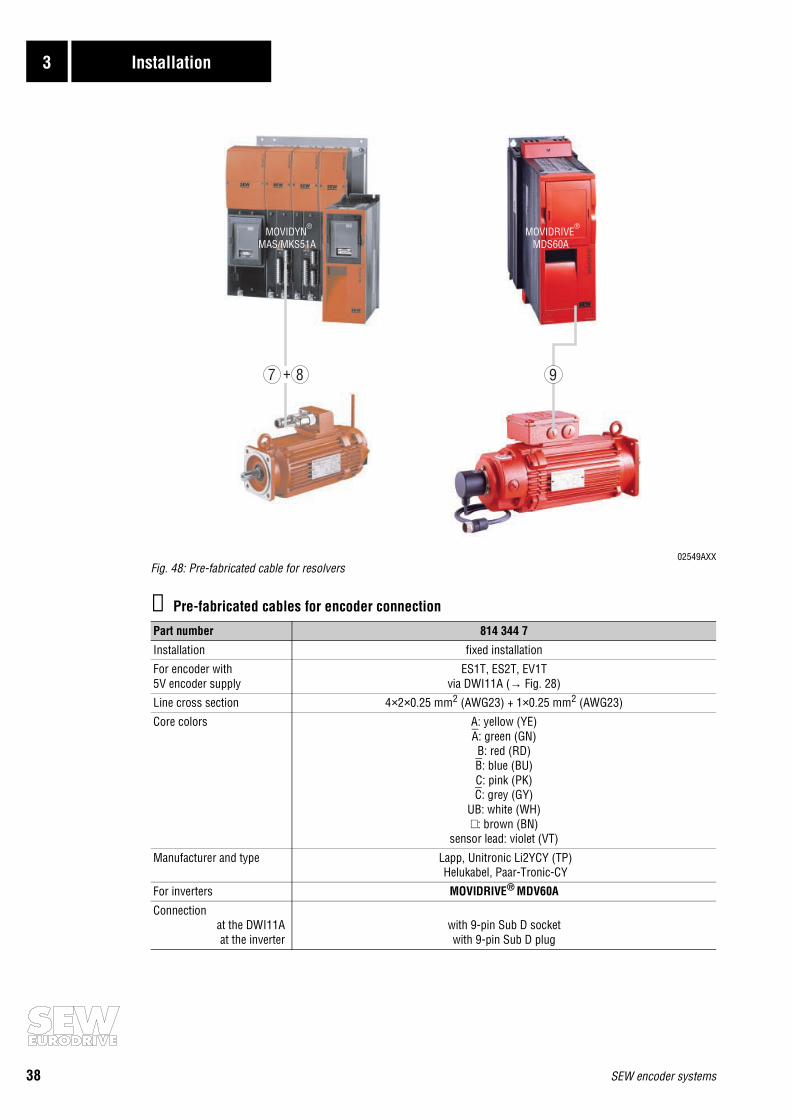
02549AXXFig. 48: Pre-fabricated cable for resolvers
① Pre-fabricated cables for encoder connection
Part number 814 344 7
Installation fixed installation
For encoder with5V encoder supply
ES1T, ES2T, EV1Tvia DWI11A (→ Fig. 28)
Line cross section 4×2×0.25 mm2 (AWG23) + 1×0.25 mm2 (AWG23)
Core colors A: yellow (YE)A: green (GN)B: red (RD)B: blue (BU)C: pink (PK)C: grey (GY)
UB: white (WH)⊥: brown (BN)
sensor lead: violet (VT)
Manufacturer and type Lapp, Unitronic Li2YCY (TP) Helukabel, Paar-Tronic-CY
For inverters MOVIDRIVE® MDV60A
Connectionat the DWI11Aat the inverter
with 9-pin Sub D socketwith 9-pin Sub D plug
MOVIDYNMAS/MKS51A
®MOVIDRIVE
MDS60A
®
7 8+ 9

SEW encoder systems 39
Installation 3
② Pre-fabricated cables for incremental TTL and sin/cos encoders
③ Pre-fabricated cables for incremental HTL encoders
Part number 198 829 8 198 828 X
Installation fixed installation trailing-cable installation
For encoders ES1T, ES2T, EV1T via DWI11A and cable 814 344 7ES1S, ES2S, EV1S, ES1R, ES2R, EV1R directly at the inverter
Line cross section 4×2×0.25 mm2 (AWG23) + 1×0.25 mm2 (AWG23)
Core colors A: yellow (YE)A: green (GN)B: red (RD)B: blue (BU)C: pink (PK)C: grey (GY)
UB: white (WH)⊥: brown (BN)
sensor lead: violet (VT)
Manufacturer and type Lapp, Unitronic Li2YCY (TP) Helukabel, Paar-Tronic-CY
Lapp, Unitronic LiYCY Helukabel, Super-Paar-Tronic-C-PUR
For inverters MOVIDRIVE® MDV60A
Connection toencoder / motor
inverter / DWI11A
with wire end sleeveWith ES1T, ES2T, EV1T connect the violet core (VT) at the encoder to UB.
With ES1S, ES2S, EV1S, ES1R, ES2R, EV1Rcut off the violet wire (VT) of the cable on the encoder side.
with 9-pin Sub D connector
Part number 198 932 4 198 931 6
Installation fixed installation trailing-cable installation
For encoders ES1C, ES2C, EV1C directly at inverter
Line cross section 5×0.25 mm2 (AWG23)
Core colors A: yellow (YE)B: red (RD)C: pink (PK)
UB: white (WH)⊥: brown (BN)
Manufacturer and type Lapp, Unitronic LiYCY Helukabel, Tronic-CY
Lapp, Unitronic FD CP Helukabel, Super-Tronic-C-PURö
For inverters MOVIDRIVE® MDV60A
Connection toencoder / motor
inverterwith core end sleeves
with 9-pin Sub D connector
40 SEW encoder systems
3 Installation
④ Pre-fabricated cables for absolute encoder
⑤ Pre-fabricated cables for absolute encoders
Part number 198 887 5 198 888 3
Installation fixed installation trailing-cable installation
For encoder AV1Y
Line cross section 3×2×0.25 mm2 (AWG23)
Core colors T+: pink (PK)T-: grey (GY)
D+: yellow (YE)D-: green (GN)
GND: brown (BN)US: white (WH)
Manufacturer and type Lapp, Unitronic Li2YCY (TP) Helukabel, Paar-Tronic-CY
Lapp, Unitronic FD CP (TP) Helukabel, Super-Paar-Tronic-C-PUR
For inverters MOVIDYN® MAS/MKS51A with option APA12MOVIDRIVE® MDS60A with option DPA11A
Connection atencoder / motor
inverterwith 17-pin socket connector SPUC 17B FRAN
with core end sleeves
Part number 198 929 4 198 930 8
Installation fixed installation trailing-cable installation
For encoder AV1Y
Line cross section 3×2×0.25 mm2 (AWG23)
Core colors T+: pink (PK)T-: grey (GY)
D+: yellow (YE)D-: green (GN)
GND: brown (BN)US: white (WH)
Manufacturer and type Lapp, Unitronic Li2YCY (TP) Helukabel, Paar-Tronic-CY
Lapp, Unitronic FD CP (TP) Helukabel, Super-Paar-Tronic-C-PUR
For inverters MOVIDRIVE® MDS60A with option DIP11A
Connection toencoder / motor
inverterwith 17-pin plug connector SPUC 17B FRAN
with 9-pin Sub D connector

SEW encoder systems 41
Installation 3
⑥ Pre-fabricated cables for absolute encoders with connection of sine signals
Part number 198 890 5 198 891 3
Installation fixed installation trailing-cable installation
For encoders AV1Y
Line cross section 5×2×0.25 mm2 (AWG23)
Core colors T+: pink (PK)T-: grey (GY)
D+: black (BK)D-: violet (VT)
GND: brown (BN)US: white (WH)A: yellow (YE)A: green (GN)B: red (RD)B: blue (BU)
Manufacturer and type Lapp, Unitronic Li2YCY (TP) Helukabel, Paar-Tronic-CY
Lapp, Unitronic FD CP (TP) Helukabel, Super-Paar-Tronic-C-PUR
For inverters MOVIDRIVE® MDV60A with option DIP11A
Connection toencoder / motor
inverterwith 17-pin socket plug SPUC 17B FRAN
with two 9-pin Sub D connectors

42 SEW encoder systems
3 Installation
⑦ Pre-fabricated cables for resolvers in motor DS56
Part number 198 672 4 198 744 5
Installation fixed installation trailing-cable installation
For resolver in motor DS56
Line cross section 4×2×0.25 mm2 (AWG23)
Core colors Ref.+: pink (PK)Ref.-: grey (GY)cos+: red (RD)cos-: blue (BU)
sin+: yellow (YE)sin-: green (GN)
TF/TH: white (WH)TF/TH: brown (BN)
Manufacturer and type Lapp, Unitronic Li2YCY (TP) Helukabel, Paar-Tronic-CY
Lapp, Unitronic FD CP (TP) Helukabel, Super-Paar-Tronic-C-PUR
For inverters MOVIDYN® MAS/MKS51A
Connection toresolver / motor
inverterwith resolver connector (Intercontec, type ASTA021NN00 10 000 5 000)
with core end sleeves
Part number 198 927 8 198 928 6
Installation fixed installation trailing-cable installation
For resolvers in motor DS56
Line cross section 4×2×0.25 mm2 (AWG23)
Core colors Ref.+: pink (PK)Ref.-: grey (GY)cos+: red (RD)cos-: blue (BU)
sin+: yellow (YE)sin-: green (GN)
TF/TH: white (WH)TF/TH: brown (BN)
Manufacturer and type Lapp, Unitronic Li2YCY (TP) Helukabel, Paar-Tronic-CY
Lapp, Unitronic FD CP (TP) Helukabel, Super-Paar-Tronic-C-PUR
For inverters MOVIDRIVE® MDS60A
Connection toresolver / motor
inverterwith resolver connector (Intercontec, type ASTA021NN00 10 000 5 000)
with 9-pin Sub D connector
SEW encoder systems 43
Installation 3
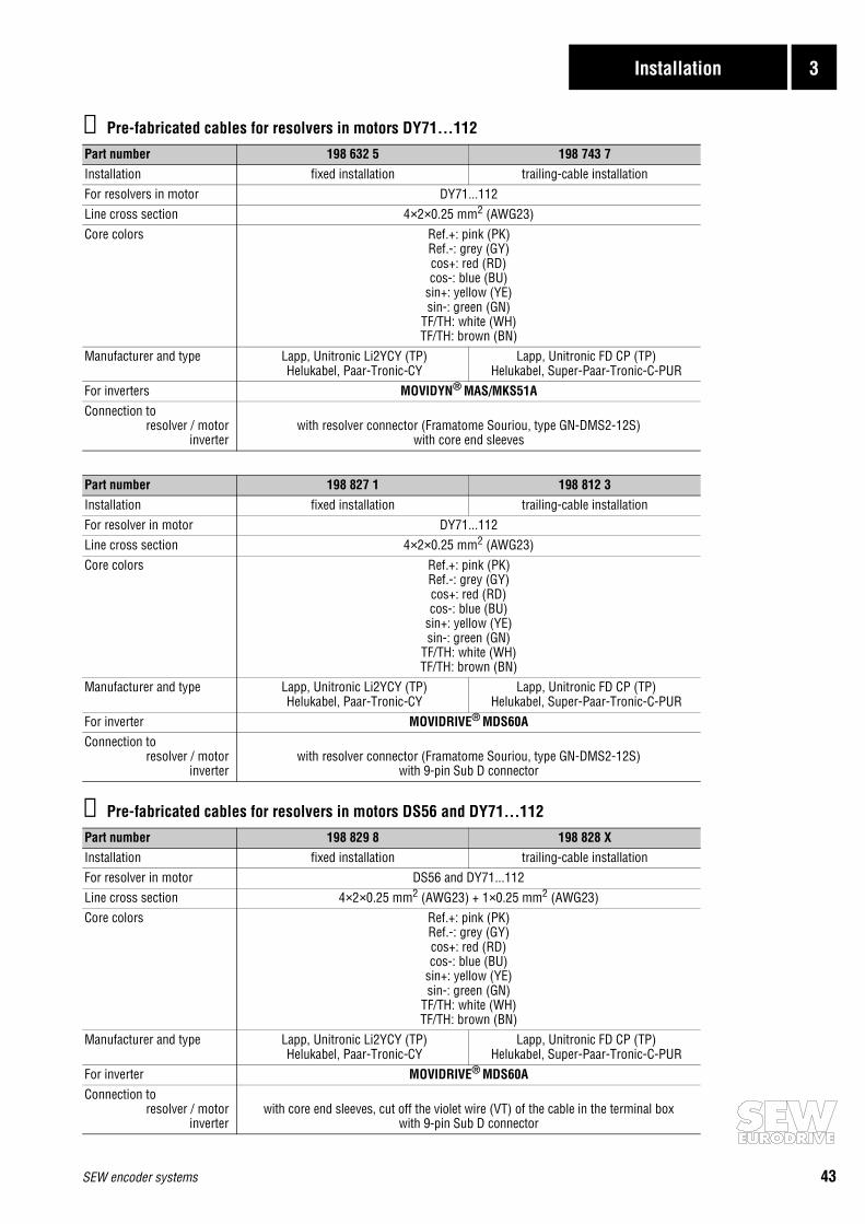
⑧ Pre-fabricated cables for resolvers in motors DY71...112
⑨ Pre-fabricated cables for resolvers in motors DS56 and DY71...112
Part number 198 632 5 198 743 7Installation fixed installation trailing-cable installationFor resolvers in motor DY71...112Line cross section 4×2×0.25 mm2 (AWG23)Core colors Ref.+: pink (PK)
Ref.-: grey (GY)cos+: red (RD)cos-: blue (BU)
sin+: yellow (YE)sin-: green (GN)
TF/TH: white (WH)TF/TH: brown (BN)
Manufacturer and type Lapp, Unitronic Li2YCY (TP) Helukabel, Paar-Tronic-CY
Lapp, Unitronic FD CP (TP) Helukabel, Super-Paar-Tronic-C-PUR
For inverters MOVIDYN® MAS/MKS51AConnection to
resolver / motorinverter
with resolver connector (Framatome Souriou, type GN-DMS2-12S)with core end sleeves
Part number 198 827 1 198 812 3Installation fixed installation trailing-cable installationFor resolver in motor DY71...112Line cross section 4×2×0.25 mm2 (AWG23)Core colors Ref.+: pink (PK)
Ref.-: grey (GY)cos+: red (RD)cos-: blue (BU)
sin+: yellow (YE)sin-: green (GN)
TF/TH: white (WH)TF/TH: brown (BN)
Manufacturer and type Lapp, Unitronic Li2YCY (TP) Helukabel, Paar-Tronic-CY
Lapp, Unitronic FD CP (TP) Helukabel, Super-Paar-Tronic-C-PUR
For inverter MOVIDRIVE® MDS60AConnection to
resolver / motorinverter
with resolver connector (Framatome Souriou, type GN-DMS2-12S)with 9-pin Sub D connector
Part number 198 829 8 198 828 XInstallation fixed installation trailing-cable installationFor resolver in motor DS56 and DY71...112Line cross section 4×2×0.25 mm2 (AWG23) + 1×0.25 mm2 (AWG23)Core colors Ref.+: pink (PK)
Ref.-: grey (GY)cos+: red (RD)cos-: blue (BU)
sin+: yellow (YE)sin-: green (GN)
TF/TH: white (WH)TF/TH: brown (BN)
Manufacturer and type Lapp, Unitronic Li2YCY (TP) Helukabel, Paar-Tronic-CY
Lapp, Unitronic FD CP (TP) Helukabel, Super-Paar-Tronic-C-PUR
For inverter MOVIDRIVE® MDS60AConnection to
resolver / motorinverter
with core end sleeves, cut off the violet wire (VT) of the cable in the terminal boxwith 9-pin Sub D connector

SEW-EURODRIVE right around the globe isyour competent partner in matters of power
transmission with manufacturing and assem-bly plants in most major industrial countries.
We are available, wherever you need us.Worldwide.
SEW-EURODRIVE GmbH & Co · P.O.Box 30 23 · D-76642 Bruchsal/GermanyTel. +49-7251-75-0 · Fax +49-7251-75-19 70 · Telex 7 822 391http://www.SEW-EURODRIVE.com · [email protected]


