
IJSRD - International Journal for Scientific Research & Development| Vol. 2, Issue 06, 2014 | ISSN (online): 2321-0613
All rights reserved by www.ijsrd.com 91
Switching Table Based Direct Torque Control of Induction Motor Drive
Saurabh Sharma1 Sandeep Kumar Gautam
2 Dr. A.K Pandey
3
1,2M.Tech Student
3Associate Professor
1,2,3Department of Electrical Engineering
Abstract— Among all control methods of induction motor
drive Direct Torque Control is very good because control
process is independent of rotor circuit parameters and also
there is no requirement of speed sensor. DTC has been used
for smooth steady state and transient performance of
induction motor. This paper presents simulink model of
switching table based DTC of an Induction Motor drive ,
various waveform of electromagnetic torque, mechanical
speed, stator currents of induction motor are also shown.
Key words: induction motor, switching table, etc.
I. INTRODUCTION
Induction motor is widely used in industry because of its
simple construction, low cost, low maintenance and good
reliability. and also it can be used in any environment
because of absence of commutator and related spark
problems. IM control methods can be divided into scalar
and vector control. The general classification of the
variable-frequency methods is presented in Fig. 1. In scalar
control, which is based on relationships valid in steady state,
only magnitude and frequency (angular speed) of voltage,
current, and flux linkage space vectors are controlled. Thus,
the scalar control does not act on space vector position
during transients. Contrarily, in vector control, which is
based on relations valid for dynamic states, not only
magnitude and frequency (angular speed) but also
instantaneous positions of voltage, current, and flux space
vectors are controlled. Thus, the vector control acts on the
positions of the space vectors and provides their correct
orientation both in steady state and during transients.
In recent years, the commercial applications of the
Field-Oriented Control (FOC) of Induction Motor (IM)
drives have greatly increased. A number of studies has been
developed to find out different solutions for the control of
the IM drives with two objectives, namely i) fulfilment of
the requirements for a precise and quick control of the motor
flux and torque, and ii) reduction of the complexity of the
algorithms involved in a FOC. The basic scheme of DSC is
preferable in the high power range applications, where a
lower inverter switching frequency can justify higher current
distortion. Differently from FOC, DTC does not tend to
reproduce the electromechanical behaviour of a dc motor
drive but is aimed at a complete exploitation of the flux and
torque-producing capabilities of an IM fed by a Voltage
Source Inverter (VSI).
The DTC scheme is characterized by the absence
of PI regulators, coordinate transformations, current
regulators and PWM signals generators.
The basic principles of flux and torque control and
the switching table are firstly presented in order to
accomplish the DTC concept. The switching strategies as
well as the influence of the torque and flux hysteresis band
amplitude on the drive behaviour are then shown. A
particular attention has been made on the analytical
relationship between the applied voltage and the
corresponding torque variation in a cycle period.
II. BASIC PRINCIPLE
In the case of voltage-source (VS) inverter-fed IM drives,
not only the stator current but also the stator flux may be
used as the torque control quantity.
Electromagnetic torque of induction motor is given by
following equation:
Tem =
Ψr
Ψs sin δΨ ..(1)
Where Ψs is the stator flux magnitude, Ψr is rotor flux
magnitude , δΨ is the torque angle and σ is the leakage
factor.
Stator flux is a state variable, which can be adjusted by
stator voltage. Stator voltage of induction motor is given as:
Usk = Rs isk + (1/ 2π 50)
+ jωkΨsk ..(2)
Where where Usk , isk , Ψsk , ωk , and are the stator voltage,
stator current, stator flux linkage vectors, and angular speed
of reference frame, respectively and the index k denotes
rotating reference frame.
Now if Rs = 0 ,
= Us =Uv …(3)
Where Uv is inverter output voltage vector.
Uv is described by following equation:
..(4)
Where Udc = udc /√ Usn andUsn is the rms value of the
phase voltage. By (3), assumes six nonzero values (active
vectors) and two zero values (zero vectors). It follows from
(2) that,
Ψs = ∫
…(5)
For six-step operation, the inverter output voltage
constitutes a cyclic and symmetric sequence of active
vectors, so that, in accordance with (3), the stator flux
moves with constant speed along a hexagonal path. The
introduction of zero vectors stops the flux, an effect known
as stop pulse, but does not change its path. There is only a
change of cycle of the voltage vector sequence.
The operation of a VS inverter-fed IM is characterized by
the following properties.
The inverter output voltage can only be in one of
two states, either active (one of the nonzero vectors
u1,...u6) or zero ( u0,u7).
The active forward vectors produce stator flux
movement with constant linear speed while the
zero vectors stop the flux; from the point of view of
torque production, the two states correspond,
respectively, to torque increase and torque
reduction conditions.
Switching Table Based Direct Torque Control of Induction Motor Drive
(IJSRD/Vol. 2/Issue 06/2014/023)
All rights reserved by www.ijsrd.com 92
The active backward vectors produce stator field
movement with constant linear speed in the
opposite direction.
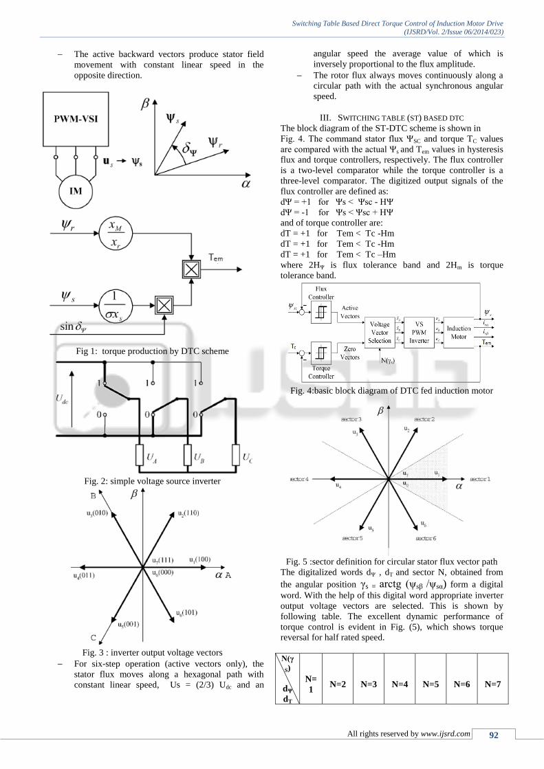
Fig 1: torque production by DTC scheme
Fig. 2: simple voltage source inverter
Fig. 3 : inverter output voltage vectors
For six-step operation (active vectors only), the
stator flux moves along a hexagonal path with
constant linear speed, Us = (2/3) Udc and an
angular speed the average value of which is
inversely proportional to the flux amplitude.
The rotor flux always moves continuously along a
circular path with the actual synchronous angular
speed.
III. SWITCHING TABLE (ST) BASED DTC
The block diagram of the ST-DTC scheme is shown in
Fig. 4. The command stator flux ΨSC and torque TC values
are compared with the actual Ψs and Tem values in hysteresis
flux and torque controllers, respectively. The flux controller
is a two-level comparator while the torque controller is a
three-level comparator. The digitized output signals of the
flux controller are defined as:
dΨ = +1 for Ψs < Ψsc - HΨ
dΨ = -1 for Ψs < Ψsc + HΨ
and of torque controller are:
dT = +1 for Tem < Tc -Hm
dT = +1 for Tem < Tc -Hm
dT = +1 for Tem < Tc –Hm
where 2HΨ is flux tolerance band and 2Hm is torque
tolerance band.
Fig. 4:basic block diagram of DTC fed induction motor
Fig. 5 :sector definition for circular stator flux vector path
The digitalized words dΨ , dT and sector N, obtained from
the angular position γs = arctg (ψsβ /ψsα) form a digital
word. With the help of this digital word appropriate inverter
output voltage vectors are selected. This is shown by
following table. The excellent dynamic performance of
torque control is evident in Fig. (5), which shows torque
reversal for half rated speed.
N(γ
S)
dΨ
dT
N=
1
N=2
N=3
N=4
N=5
N=6
N=7

Switching Table Based Direct Torque Control of Induction Motor Drive
(IJSRD/Vol. 2/Issue 06/2014/023)
All rights reserved by www.ijsrd.com 93
dΨ=
1
dT
= 1
u2(11
0)
u3(01
0)
u4(01
1)
u5(00
1)
u6(10
1)
u1(10
0)
dT
= 0
u7(11
1)
u0(00
0)
u7(11
1)
u0(00
0)
u7(11
1)
u0(00
0)
dT
= -
1
u6(10
1)
u1(10
0)
u2(11
0)
u3(01
0)
u4(01
1)
u5(00
1)
dΨ=
0
dT
= 1
u3(01
0)
u4(01
1)
u5(00
1)
u6(10
1)
u1(10
0)
u2(11
0)
dT
= 0
u0(00
0)
u7(11
1)
u0(00
0)
u7(11
1)
u0(00
0)
u7(11
1)
dT
= -
1
u5(00
1)
u6(10
1)
u1(10
0)
u2(11
0)
u3(01
0)
u4(01
1)
Table 1: Selection Of Voltage Vector In St-Dtc
The characteristic features of the ST-DTC scheme of
include:
Nearly sinusoidal stator flux and current
waveforms; the harmonic content is determined by
the flux and torque controller hysteresis bands HΨ
and Hm ;
Excellent torque dynamics;
Flux and torque hysteresis bands determine the
inverter switching frequency, which varies with the
synchronous speed and load conditions.
IV. SIMULINK MODEL FOR ST BASED DTC OF INDUCTION
MOTOR DRIVE
Ratings of induction motor used are:
Power = 3kw
Voltage = 380V
Stator current = 6A
Frequency = 50Hz
Nominal Torque = 20Nm
Rated speed = 1415rpm
Stator resistance, Rs = 1.77Ω
Rotor resistance, Rr = 1.34 Ω
Stator leakage inductance, Ls= 13.93 mH
Rotor leakage inductance, Lr =12.12mH
Mutual Inductance, Lm = 369mH
V. SIMULATION RESULT
After successful completion of simulation of ST based direct
torque control of induction motor drive various waveforms
of electromagnetic torque, reference torque, mechanical
speed of motor, slip speed, stator currents of motor, stator
and rotor flux space vectors ,are obtained and motor torque
is compared with reference torque. Above mentioned
waveforms are shown in following figure:
Fig. 5:comparison b/w motor torque Tem and reference
torque Tref
Fig. 6: Load Torque Tl
Fig. 7: Reference Torque Tref
Fig. 8: mechanical speed of motor ωm versus time

Switching Table Based Direct Torque Control of Induction Motor Drive
(IJSRD/Vol. 2/Issue 06/2014/023)
All rights reserved by www.ijsrd.com 94
Fig. 9: angular speed of induction motor ωm , rotor speed ωr
and slip speed ωslip
Fig. 10 :stator current of induction motor
Fig. 11:stator flux and rotor flux vector trajectories
VI. CONCLUSION
Switching table based direct torque control of induction
motor drive is successfully simulated by using MATLAB 13
software. It is clear from the waveform of electromagnetic
torque of induction motor that it follows the values of
reference torque. Torque of induction motor is directly
controlled using DTC without affecting rotor circuit
parameters and without using any speed or position sensing.
This technique also gives very good transient as well as
steady state performance control induction motor.
REFERENCES
[1] U. Baader, ―High dynamic torque control of
induction motor in stator flux oriented coordinates‖
(in German), ETZ Arch., vol. 11, no. 1, pp 11–17,
1998.
[2] U. Baader, M. Depenbrock, and G. Gierse, ―Direct
self control (DSC) of inverter-fed-induction
machine—A basis for speed control without speed
measurement,‖ IEEE Trans. Ind. Applicat., vol. 28,
pp. 581–588, May/June 1992.
[3] M. Bertoluzzo, G. Buja, and R. Menis, ―Analytical
formulation of the direct control of induction motor
drives,‖ in Proc. IEEE Int. Symp. Industrial
Electronics, 1999, pp. 14–20.
[4] ―Operation of DFTC IM drives under estimation
process errors,‖ in Proc. Int. Conf. Power
Electronics and Motion Control, 2000, pp. 1.27–
1.34.
[5] F. Blaschke, ―The principle of field-orientation as
applied to the transvector closed-loop control
system for rotating-field machines,‖ Siemens Rev.,
vol. 34, pp. 217–220, 1972.
[6] M. Bodson, J. Chiasson, and R. Novotnak, ―High
performance induction motor control via input-
output linearization,‖ IEEE Contr. Syst. Mag., vol.
14, pp. 25–33, Aug. 1994.
[7] I. Boldea and S. A. Nasar, ―Torque vector control.
A class of fast and robust torque, speed and
position digital controllers for electric drives,‖
Electromech. Power Syst., vol. 15, pp. 135–147,
1988.
[8] Electric Drives. Boca Raton, FL: CRC Press, 1999.
[9] F. Bonanno, A. Consoli, A. Raciti, and A. Testa,
―An innovative direct self-control scheme for
induction motor drives,‖ IEEE Trans. Power
Electron., vol. 12, pp. 800–806, Sept. 1997.
[10] B. K. Bose, Modern Power Electronics and AC
Drives. Englewood Cliffs, NJ: Prentice-Hall, 2001.
[11] G. Buja, D. Casadei, and G. Serra, ―DTC-Based
strategies for induction motor drives,‖ in Proc.
IEEE IECON’97, vol. 4, 1997, pp. 1506–1516.
[12] G. Buja, ―A new control strategy of the induction
motor drives: The direct flux and torque control,‖
IEEE Ind. Electron. Newslett., vol. 45, pp. 14–16,
Dec. 1998.
[13] L. A. Cabrera, M. E. Elbuluk, and D. S. Zinger,
―Learning techniques to train neural networks as a
state selector for inverter-fed induction machines
using direct torque control,‖ IEEE Trans. Power
Electron., vol.
12, pp. 788–799, Sept. 1997.
[14] [D. Casadei, F. Profumo, G. Serra, and A. Tani,
―FOC and DTC: Two viable schemes for induction
motors torque control,‖ IEEE Trans. Power
Electron., vol. 17, pp. 779–787, Sept. 2002.
[15] D. Casadei, G. Serra, and A. Tani, ―Constant
frequency operation of a DTC induction motor
drive for electric vehicle,‖ in Proc. ICEM’96, vol.
3, 1996, pp. 224–229.
[16] A. D. Cheok and P. H. Hoon, ―A new torque
control method for switched reluctance motor

Switching Table Based Direct Torque Control of Induction Motor Drive
(IJSRD/Vol. 2/Issue 06/2014/023)
All rights reserved by www.ijsrd.com 95
drives,‖ in Proc. IEEE IECON’00, 2000, CD-
ROM.
[17] V. Cascone, L. Mantica, and M. Oberti, ―Three
level inverter DSC control strategy for traction
drives,‖ in Proc. 5th Eur. Conf. Power Electronics
and Applications, vol. 1, Florence, Italy, 1989, pp.
135–139.
[18] S. Chung, H.-S. Kim, C.-G. Kim, and M.-J. Youn,
―A new instantaneous torque control of PM
synchronous motor for high-performance direct
drive applications,‖ IEEE Trans. Power Electron.,
vol. 13, pp. 388–400, May 1998.
[19] M. Depenbrock, ―Direct self control of inverter-fed
induction machines,‖ IEEE Trans. Power Electron.,
vol. 3, pp. 420–429, Oct. 1988.
[20] ―Direct self-control of the flux and rotary moment
of a rotary-field machine,‖ U.S. Patent 4 678 248,
July 7, 1987.
[21] ―Direct torque control—The world’s most
advanced AC drive technology,‖ ABB Finland,
Helsinki, Tech. Guide 1, 1996.
[22] C. French and P. Acarnley, ―Direct torque control
of permanent magnet drives,‖ IEEE Trans. Ind.
Applicat., vol. 32, pp. 1080–1088, Sept./Oct. 1996.
[23] P. Z. Grabowski, M. P. Kazmierkowski, B. K.
Bose, and F. Blaabjerg, ―A simple direct-torque
neuro-fuzzy control of PWM-inverter-fed induction
motor drive,‖ IEEE Trans. Ind. Electron., vol. 47,
pp. 863–870, Aug. 2000.
[24] T. G. Habetler and D. D. Divan, ―Control strategies
for direct torque control using discrete pulse
modulation,‖ IEEE Trans. Ind. Applicat., vol. 27,
pp. 893–901, Sept./Oct. 1991.
[25] T. G. Habetler, F. Profumo, and M. Pastorelli,
―Direct torque control of induction machines over a
wide speed range,‖ in Conf. Rec. IEEE-IAS Annu.
Meeting, 1992, pp. 600–606.
[26] T. G. Habetler, F. Profumo, M. Pastorelli, and L.
M. Tolbert, ―Direct torque control of induction
motor using space vector modulation,‖ IEEE Trans.
Ind. Applicat., vol. 28, pp. 1045–1053, Sept./Oct.
1992.
[27] M. E. Haque, L. Zhong, and M. F. Rahman, ―A
sensorless speed estimation for application in a
direct torque controller of an interior permanent
magnet synchronous motor drive, incorporating
compensation of offset error,‖ in Proc. IEEE
PESC’02, vol. 1, 2002, pp. 276–281.
[28] F. Hoffman and M. Janecke, ―Fast torque control of
an IGBT-inverter- fed tree-phase A.C. drive in the
whole speed range—Experimental result,‖ in Proc.
EPE Conf., 1995, pp. 3.399–3.404.
[29] N. R. N. Idris and A. H. Yatim, ―Reduced torque
ripple and constant torque switching frequency
strategy for induction motors,‖ in Proc. IEEE
APEC’00, 2000, pp. 154–161.
[30] T. Noguchi and I. Takahashi, ―Quick torque
response control of an induction motor based on a
new concept‖, IEEJ Tech. Meeting Rotating Mach.
RM84-76, 61–70 (1984), (in Japanese).
[31] I. Takahashi and T. Noguchi, ―A new quick-
response and high efficiency control strategy of an
induction machine‖, IEEE Trans. Ind. Applicat. 22,
820–827 (1986).
[32] I. Takahashi and Y. Ohmori, ―High-performance
direct torque control of an induction motor‖, IEEE
Trans. Ind. Applicat. 25, 257–264 (1989).
[33] M. Depenbrok, ―Direct self-control (DSC) of
inverter-fed induction machine‖, IEEE Trans.
Power Electron. 3, 20–429 (1988).
[34] M. Depenbrock and A. Steimel, ―High power
traction drives and convertors‖, Proc. Elect. Drives
Symp.’90, 1–9 (1990).
[35] I. Boldea and S.A. Nasar, ―Torque vector control
(TVC)-A class of fast and robust torque speed and
position digital controller for electric drives‖, Proc.
EMPS’88 Conf. 15, 135–148 (1988).
[36] T. Ohtani, N. Takada, and K. Tanaka, ―Vector
control of induction motor without shaft encoder‖,
IEEE Trans. IA 28 (1), 157– 164 (1992). 252 Bull.
Pol. Ac.: Tech. 54


