
SURVEYING THE UNDERGROUND
A Surveyor’s Guide to Subsurface Utility Location & Mapping
Maryland Society of SurveyorsSpring Technical Conference
April 20, 2017
Michael T. Maguire, MA, LSJohn P. Berrettini

1
SURVEYING THE UNDERGROUNDAgenda
• Introduce ASCE 38-02 & Subsurface Utility Engineering (SUE).
• One Call System • ALTA/NSPS Land Title Surveys & Utilities
• Review technical aspects of locating UG utilities• Field Demonstration – Designating & Test Holes• Answer questions about surveying & mapping UG
utilities
THE CHALLENGE
Source: Federal Laboratory Consortium for Technology Transfer
COMPLEX UTILITY LAYERS UNDERGROUND
THE CHALLENGE INCREASING COMPLEXITY UNDERGROUND

2
INCREASING COMPLEXITY UNDERGROUND
WHAT ARE TRADITIONAL METHODS TO MAP UTILITIES?
Records researchField survey of surface features
• Valves, hand boxes, meters, manholes, hydrantsPerhaps locate One Call - 811 marks if found in fieldFit record information to surface evidence & marksDisclaim responsibility for underground utilities – “per plan”
RECORDS DON’T TELL THE WHOLE STORY.
Utility records are not always: • In existence
• Lost• Never drawn
• Available• Homeland Security• Privacy concerns• Personnel and other costs for utilities to share records
• Reliable
RECORDS DON’T TELL THE WHOLE STORY.
Records may be schematic onlyRecords may be out of date
• Utilities modified but no records made of field changesRecords refer to conditions that have changed
• Roads widened“As-builts” may not always be

3
WHAT HAPPENS IF RELIABLE INFORMATION IS NOT AVAILABLE?Incomplete or inaccurate base dataDesigns that cannot be executed or constructed as plannedConstruction delaysRe-designsChange ordersBack chargesDamagesInsurance claimsLoss of profitsLoss of client confidence, loss of client
SURVEYING THE UNDERGROUND
Miss Utility MD – 811 - One Call
Notification Center
Marking by member utilities – multiple different locators
Ticket system per site, per utility
Primarily for Excavation
Private utilities not usually marked (65% +/_ of all utilities)
Designer Ticket – October 1, 2010• 15 day response time.• Informational Purposes Only• Not liable for incomplete or inaccurate information provided• Abandoned/ unknown utilities not addressed• Something for (almost) nothing – ID of utilities
PRIVATE UTILITIES ARE NOT MARKED BY MISS UTILITY
DISCLAIMER #1
CAUTION!!THE LOCATIONS OF ALL EXISTING UNDERGROUND UTILITIES SHOWN ON THIS PLAN ARE BASED UPON ABOVEGROUND EVIDENCE (INCLUDING BUT NOT LIMITED TO MANHOLES AND INLETS, VALVES AND MARKS MADE UPON THE GROUND BY OTHERS) AND ARE SPECULATIVEIN NATURE. THERE MAY ALSO BE OTHER EXISTING UNDERGROUND UTILITIES FOR WHICH THERE IS NO ABOVEGROUND EVIDENCE [OR] FOR WHICH NO ABOVEGROUND EVIDENCE WAS OBSERVED. EXACT LOCATIONS OF SAID EXISTING UNDERGROUND UTILITY SHALL BE VERIFIED BY THE CONTRACTOR PRIOR TO ANY AND ALL CONSTRUCTION.

4
DISCLAIMER #2
LOCATION OF ALL UNDERGROUND UTILITIES ARE APPROXIMATE, SOURCE INFORMATION FROM PLANS AND MARKINGS HAS BEEN COMBINED WITH OBSERVED EVIDENCE OF UTILITIES TO DEVELOP A VIEW OF THOSE UNDERGROUND UTILITIES. HOWEVER, LACKING EXCAVATION, THE EXACT LOCATION OF UNDERGROUND FEATURES CANNOT BE ACCURATELY, COMPLETELY AND RELIABLY DEPICTED. WHERE ADDITIONAL OR MORE DETAILED INFORMATION IS REQUIRED, THE CLIENT IS ADVISED THAT EXCAVATION MAY BE NECESSARY.APPROXIMATE LOCATION OF UNDERGROUND UTILITIES ARE SHOWN PER PRIVATE UTILITY MARKOUT PERFORMED BY INSIGHT ON FEBRUARY 25, 2015 AND JUNE 27, 2016 AND FIELD LOCATED WITH CONVENTIONAL FIELD SURVEY UNLESS OTHERWISE NOTED.
DISCLAIMER #2 - CONTINUED
UTILITIES:THE FOLLOWING COMPANIES WERE NOTIFIED BY DELMARVA MISS UTILITY SYSTEM (1-800-552-7001) AND REQUESTED TO MARK OUT UNDERGROUND FACILITIES AFFECTING AND SERVICING THIS SITE. THE UNDERGROUND UTILITY INFORMATION SHOWN HEREON IS BASED UPON THE UTILITY COMPANIES RESPONSE TO THIS REQUEST. SERIAL NUMBER(S) A411400590.
UTILITY COMPANY PHONE NUMBER
SUE
THE NEED TO KNOW HORIZONTAL AND VERTICAL POSITIONS & TYPE, SIZE AND LOCATION OF EXISTING SUBSURFACE UTILITIES
LED TO THE DEVELOPMENT OF SUBSURFACE UTILITY ENGINEERING
SO-DEEP, INC. – ORIGINAL SUE COMPANY
19901970 TODAY
Garon Stutzman @WGL
Stutzman forms So‐Deep, Inc.
1981
Fairfax Co., VA – 1st locating contract
1982
Jim Anspach – adds geophysical locating
1983
1985
VDOT saves big $$$ using So‐Deep service set19
85
1st Statewide VDOT contract to So‐Deep19
83
CNA issues professional liability policy
WSSC requires professional seal for locating results
1988
SUE “named” by So‐Deep
1989
1989
VA Courts find So‐Deep “professional”
2000
FHWA CI/ASCE38‐02

5
SUE & FHWA1990’S – (Early) – Federal Highway Administration (US DOT)
• Aggressively promotes use of SUE• Defines “quality level” outcomes
• ‘D’ –records only• ‘C’ – adds surveyed utility features• ‘B’ – includes surface geophysical techniques to determine the existence
and horizontal position of utilities • ‘A’ –excavation to determine the precise H & V position, and type, size,
material and condition of underground utilities and structures
1990’s – (Late) • FHWA funds Purdue University study
• $4.62 in avoided costs for every dollar spent on SUE activities• FHWA helps fund development of national standard to classify utility data
CI/ ASCE 38-02
FHWA REMAINS AN ADVOCATE
https://www.fhwa.dot.gov/design/sue/suebrochure.cfm

6
CI/ ASCE 38-02Standard Guideline for the Collection and Depiction of
Existing Subsurface Utility Data©2003 – American Society of Civil Engineers
• Increasing complexity of national subsurface infrastructure • Subsurface “unknowns” create risks on construction
projects– Many records are inaccurate, incomplete, out of date
• One Call-811 – in most states a construction excavation period service
– Post-design & after bidding– Some States have Designer Tickets – Informational only, – USUALLY - NO LIABILITY FOR INACCURATE
INFORMATION– When conflicts arise during construction solutions are costly
– change orders, extra work orders, insurance payouts and contingency pricing
ASCE 38-02Scope of 38-02
• Consensus standard guideline• Defines quality of utility depictions
• Associated attribute data • Addresses implementation
• Methods• Available technologies • Communication of data
Intent of 38-02• Establish classification system to describe quality of
data associated with existing subsurface utilities• Facilitate communication about the quality of utility
data needed or provided for construction documents
KEY TERMSDesignating
• Interpret the presence of subsurface utility through surface geophysical methods • Mark its approximate horizontal position on the ground
Locating• Expose and record the precise vertical and horizontal location of a utility.
Utility Quality Level • A professional opinion of the quality and reliability of utility information.
Utility Depiction• A visual image of existing utility information in a computer-aided design and drafting
system (CADD) or on project plan sheets.
QUALITY LEVEL ‘D’QL D
• Information derived from existing records • State and local utility departments• One Call Center• Landowners• Internet• Utility companies
• Types of Records• Construction Drawings• Conduit , Distribution and Transmission Maps• As-builts• Oral Histories
• May include a field visit to look for visual cues to utility systems
• Composite drawing plotted for schematic representation without registration to ground features – all representation are at QL D
• May be adequate for preliminary planning purposes

7
QUALITY LEVEL ‘C’QL C
• Perform QL D tasks• Identify and field survey, process and plot utility surface
features• Correlate applicable utility records to surveyed features
considering record utility system geometries• Determine conflicts between records and surface features
and attempt to resolve discrepancies, if possible• The Information obtained by surveying and plotting visible
above-ground utility features and by using professional judgment in correlating this information to QL D information may result in a combination of QL C and QL D depictions
QUALITY LEVEL ‘B’QL B
• Perform QL C Tasks • Select an appropriate suite of surface geophysical methods• Apply surface geophysics to search for utilities• Interpret the geophysics in the field or office depending on
method• Mark and survey indications of subsurface utilities• Depict approximate horizontal positions of all detected utilities• Surveys of depicted positions must be merged with field
records & historic documentation through professional analysis and judgment to produce final mapping.
• QLB data to be reproducible by surface geophysics at any point of depiction
• Positions surveyed to applicable project standards• Recommend to project owner when additional methods such
as test holes may be needed to determine positions• May result in a combination of QL B, C & D depictions
SURVEYING THE UNDERGROUND
PENN DOT DESIGN MANUAL
Note that surveying existing one-call marks does not lead to QL B data, since the genesis of the marks was not under the direct responsible charge of the professional certifying the QL B depictions, and one-call generally does not address unknown utilities, privately owned utilities, utilities without records, abandoned utilities, and so on.
Nor does the professional have knowledge of the field technician's qualifications, training, and level of effort.
QUALITY LEVEL ‘A’QL A
• Perform QL B tasks at appropriate project locations• Excavate test holes to expose the utility to be measured• Minimally intrusive excavation
• Air-vacuum & sometimes hydro-vacuum extraction• Hand dig• Sometimes as built measurements during construction
• Actual exposure or verification of previously exposed and surveyed utilities and subsequent measurement of subsurface utilities, usually at a specific point
• Horizontal and vertical position, existing grade at ground surface, size and configuration of utility, material type, general condition, ground condition encountered
• Precise horizontal and vertical positions reported• Accuracy is typically set to 15-mm (0.05 feet) vertical and to the specified
horizontal survey and mapping accuracy of the project

8
ENGINEER’S RESPONSIBILITIESAdvise owner of potential utility impacts on projectInform and educate the project owner about quality levels
• costs and benefits of eachRecommend QL, scope, depiction
• required quality level may vary across project• Recommend formatting of deliverables to be maintained across
the project team and throughout the project lifeDiscuss sequence of acquiring appropriate quality level dataRecommend quality level upgrades as indicated by design needs
Follow one-call statutes, if any apply; e.g. designer ticket number in VA.
OWNER’S RESPONSIBILITIESReview scope with engineer; amend or approve as appropriate Assist in contact with existing utility owners; (may improve access to records)Review quality levels with project team; approve format of deliverables for all team membersNotify the engineer of suspected deficiencies in the utility depiction if familiar with site and utility systems in placeFurnish utility information to utility owners for utility marking for construction (one-call systems)
ASCE 38-02ASCE 38-02 Originally established for transportation (highway) projects
• Generally public utilities (with records) involved Can be applied to site specific design projects
• Shortage of available (private) utility records add to challenges on site specific projects
• Patterns of utility configurations are often less regular (and predictable) than in or through transportation corridors
SURVEYING THE UNDERGROUND
Professional SUE providers use ASCE 38-02 as their professional framework for methods and procedures to meet standards of professional careSUE is distinctly different from One Call - 811
• Meticulous care in research, field investigation – from mains to mechanical room, search & trace unknowns, all conductors, active & abandoned , survey, map, correlate with records
• Comprehensive consideration of all utilities; known and unknown; public & private, active & abandoned
• QL labels inform designer about the reliability of utility • Test holes are excavated to validate utility designating• Comprehensive investigation enables SUE providers to
assume professional liability
9
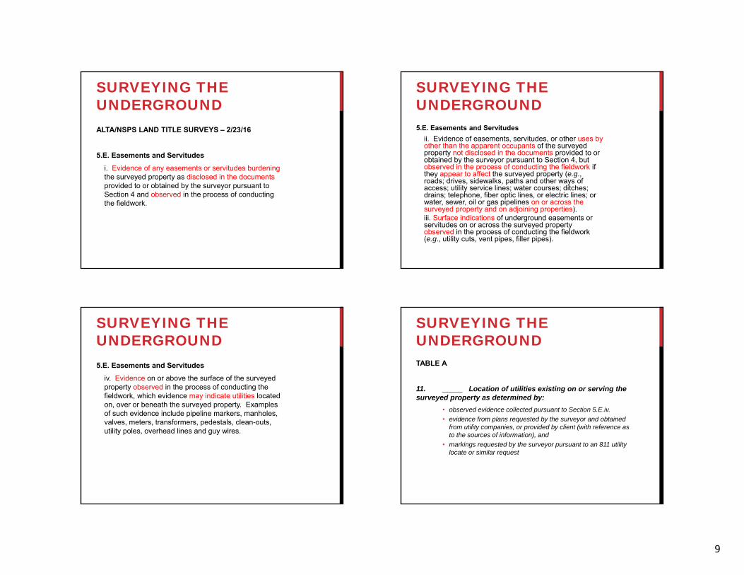
SURVEYING THE UNDERGROUNDALTA/NSPS LAND TITLE SURVEYS – 2/23/16
5.E. Easements and Servitudesi. Evidence of any easements or servitudes burdening the surveyed property as disclosed in the documents provided to or obtained by the surveyor pursuant to Section 4 and observed in the process of conducting the fieldwork.
SURVEYING THE UNDERGROUND5.E. Easements and Servitudes
ii. Evidence of easements, servitudes, or other uses by other than the apparent occupants of the surveyed property not disclosed in the documents provided to or obtained by the surveyor pursuant to Section 4, but observed in the process of conducting the fieldwork if they appear to affect the surveyed property (e.g., roads; drives, sidewalks, paths and other ways of access; utility service lines; water courses; ditches; drains; telephone, fiber optic lines, or electric lines; or water, sewer, oil or gas pipelines on or across the surveyed property and on adjoining properties).iii. Surface indications of underground easements or servitudes on or across the surveyed property observed in the process of conducting the fieldwork (e.g., utility cuts, vent pipes, filler pipes).
SURVEYING THE UNDERGROUND5.E. Easements and Servitudes
iv. Evidence on or above the surface of the surveyed property observed in the process of conducting the fieldwork, which evidence may indicate utilities located on, over or beneath the surveyed property. Examples of such evidence include pipeline markers, manholes, valves, meters, transformers, pedestals, clean-outs, utility poles, overhead lines and guy wires.
SURVEYING THE UNDERGROUNDTABLE A
11. _____ Location of utilities existing on or serving the surveyed property as determined by:
• observed evidence collected pursuant to Section 5.E.iv. • evidence from plans requested by the surveyor and obtained
from utility companies, or provided by client (with reference as to the sources of information), and
• markings requested by the surveyor pursuant to an 811 utility locate or similar request

10
SURVEYING THE UNDERGROUNDTABLE A, Item 11
Representative examples of such utilities include, but are not limited to:• Manholes, catch basins, valve vaults and other surface indications
of subterranean uses;
• Wires and cables (including their function, if readily identifiable) crossing the surveyed property, and all poles on or within ten feet of the surveyed property. Without expressing a legal opinion as to the ownership or nature of the potential encroachment, the dimensions of all encroaching utility pole crossmembers or overhangs; and
• Utility company installations on the surveyed property.
SURVEYING THE UNDERGROUNDTABLE A, Item 11
Note to the client, insurer, and lender - With regard to Table A, item 11, source information from plans and markings will be combined with observed evidence of utilities pursuant to Section 5.E.iv. to develop a view of the underground utilities. However, lacking excavation, the exact location of underground features cannot be accurately, completely, and reliably depicted. In addition, in some jurisdictions, 811 or other similar utility locate requests from surveyors may be ignored or result in an incomplete response, in which case the surveyor shall note on the plat or map how this affected the surveyor’s assessment of the location of the utilities. Where additional or more detailed information is required, the client is advised that excavation and/or a private utility locate request may be necessary.
QUESTIONS?
What’s next• Locating Theory and Practice• QLB and QLA
LOCATING THEORY & PRACTICEBasic introduction to utility detection theory and methods
• Electromagnetic Pipe and Cable Detection• Ground Penetrating Radar
Utility Designating – Quality Level B• making a more accurate, more complete plan view utility map
Utility Locating (Test Holes) – Quality Level A• when x, y, and z accuracy and precision are critical and to
validate mapping

11
ELECTROMAGNETIC PIPE AND CABLE LOCATING SOME DEFINITIONS:
Signal: a flow of alternating electrical current at a set frequency on conductors such as metallic pipes, wires or cablesConductor: a linear object that electrical current can travel through (in our case… a utility pipe, wire or cable)Magnetic Field: a cylindrical field that forms around a conductor when current is flowing through it
PIPE AND CABLE LOCATING INSTRUMENT SETS• Typically a two piece transmitter and receiver set• Transmitter produces tracing signal (current) that can be
applied to a metallic conductor to generate a magnetic field.
• Receiver collects and processes data about the magnetic field and provides feedback in the form of sounds, signal strength, depth information, etc.
DETECTING MAGNETIC FIELDS
We don’t really “locate underground utilities”What we really do is infer locations based on detected magnetic fields
APPLYING THE SIGNALDIRECT CONNECT – ACCESS TO THE CONDUCTOR

12
APPLYING THE SIGNALINDUCTIVE CLAMPING – ACCESS TO CABLES
APPLYING THE SIGNALSURFACE INDUCTION – “DROP BOX” OR “SWEEP”
PASSIVE SIGNAL DETECTIONPOWER AND RADIO SIGNALS CREATE MAGNETIC FIELDS THAT CAN BE DETECTED
ALTERNATING CURRENTAND FREQUENCY
• The frequency measured in Hertz (Hz) is the number of times (cycles) per second that the current begins in one direction, changes to opposite direction and then returns to the original direction. Normal house current in US is…
• There are 10 cycles represented above. If it takes 2 seconds to transmit these 10 cycles the frequency is…
60 Hz
5 Hz

13
ALTERNATING CURRENTAND FREQUENCY
• Common locating frequencies generated by pipe and cable transmitters range from 512 Hz to 480 kHz
• Low frequency good for long locates on good conductors and don’t easily jump on to adjacent conductors. Not good forinduction.
• High frequency can overcome resistance in the conductor and are good for induction… good for sweeping.
• Passive receivers can detect the 60 Hz signal on energized electrical lines.
• Some frequencies are better suited to certain utilities and situations.
• A variety of frequencies should be available to locate the wide range of utility types and situations encountered in the field.
COMMON UTILITY PROPERTIESWHAT CAN YOU EXPECT?
Electrical Lines (copper, aluminum)• Designed to carry a current so by their nature are easier to
detect. • Passive locating in power mode - 60 Hz
Telephone Lines (copper pairs w/ bonding sheath)• Also designed to carry a current (at a low voltage) so also easy
to detect.Fiber Optic / Other Data Lines
• The individual fiber strands are made of glass (non-conductive) but may have metallic sheath surrounding the strands.
• If no conductor present they can’t be detected. May need to rely on buried tracer or snake an adjacent conduit.
• CAT 5, CAT 6 and similar data cables are copper but often not grounded. Difficult to trace.
COMMON UTILITY TYPES…Gas Lines (steel or wrapped steel, cast, copper plastic)
• Steel lines locate well. Lengths are welded together so current flows freely. However, insulators are sometimes placed in the line to electrically isolate segments and reduce corrosion.
• Copper, not common for gas but easy to locate. • Cast iron gas can be good or bad. Can also have insulators. • Plastic gas lines are required to be buried with a trace wire…
good if you can find it to direct connect. Trace wires often corrode and / or are not continuous.
Water Lines (ductile/ cast iron, steel, AC, • If metallic (cast or ductile iron, steel, copper, etc.) can be located
but generally buried deeper than other lines. Bell and spigot joints (push on with gasket) can resist current flow. Hard to trace for long distances because current travels to ground.
• If non-conductive (plastic, asbestos cement, etc.) will need trace wire to detect. Acoustic methods might be used but carries some risk.
Gravity Sewers• Usually rely on surface features and direction / next
connecting structure to determine location• Can be snaked or videoed and then detected (cost and labor
intensive) Other / less common…
• Steam or high temp water is usually welded steel i.e. good to detect.
• Chilled water can be made from same materials as water lines with similar characteristics.
• Irrigation almost always plastic. Can detect control wiring. Often considered expendable and/ or not costly to repair or replace.
• Septic systems – challenging due to lack of access to system components and non-conductive materials
COMMON UTILITY TYPES…

14
INFLUENCING FACTORS: ELECTROMAGNETIC PIPE AND CABLE LOCATING
Depth of bury • Shallow - stronger field easily detected• Deep – weaker field, more difficult to detect
Physical access to utility • surface induction may be the only option for applying signal
Utility type and material • The easiest utilities to detect are conductive cables and pipes with
minimal resistance to current travel.Conductor congestion both above and below ground
• Interference and signal bleed to adjacent conductors making it difficult to interpret the multitude of magnetic fields present
• Fences, guardrails, building walls and columns and overhead cable can all be sources of interference.
BASIC GPR PRINCIPALSElectromagnetic “pulses” of energy are emitted from transmitting antenna downward through the groundThe pulses reflect back from objects that contrast with the surrounding soilsThe reflections are detected by the receiving antenna and processed through circuitry and software to produce an “image” of the reflections
MODERN GPR UNITS CLASSIC GPR DATAA SINGLE SCAN (CROSS SECTION)

15
GPR REFLECTIONSHYPERBOLIC SHAPE
GPR SEARCH PATTERN
EM VS GPR COMPARISONEM Pipe and Cable Locators Ground Penetrating Radar
Works in variety of soils Wet or conductive soils will limit or prevent use
Utilities need to be conductive (or snaked with conductor)
Non-conductive utilities can be detected
Small diameter utilitescan be detected
Small diameter utilities hard to detect
Instrument detects magnetic field Instrument detects reflected wave
Best employed on nearly all investigations
Best employed when circumstances dictate
Useful for linear utilities (lines) Useful for tanks, drums, vaults, voids, etc.
Best bang for buck on most utilities Expensive to deploy.Used when needed.
DESIGNATING – QL BSTANDARDIZED APPROACH
Records Research – Utility Inventory… at least know what’s knownField Investigation
• Geophysical detection tools (utility locating instruments)• Interpret, verify and/ or correct information from utility records• Visible field evidence
Field Marking in APWA-ULCC colors• Red–electric, blue-water, yellow – gas, etc.
Field Sketch, Survey Collect and Reduce to CAD Map• Utilize survey control established for project
Review in office and / or field• Reconcile utility records, field sketches and notes with final
mapping. Revisit the site to iron out discrepancies• Determine what utilities should be represented at QL C or D• Documented Results Represent “Professional Opinion”
• Most reliable location of utilities short of excavation and eyes on• Includes private, public, abandoned and undocumented utilities

16
UTILITY RECORDS UTILITY RECORDSWHY BOTHER? YOU ARE GOING TO LOCATE EVERYTHING ANYWAY RIGHT?
Without records:• Some important information may be missing
• Utility sizes, materials, etc. • Utilities might be missed if:
• There are no visible indications that they are present • They are non-conductive• They are conductive but aren’t “discovered”
• There will be knowledge of them if they are missed. no knowledge = no warning = Potential Disaster
The best way to ensure a utility does not go undocumented is to have a credible record
indicating its existence.
RECORD TYPESFROM VERY GENERAL TO VERY DETAILED
FIBER ROUTE MAP WSSC AS-BUILT
System Maps / Schematics• Indication of existence• Difficult to discern location
(somewhere in/ near street?)• Surface features not shown
Engineering As-builts• Good indication of existence• Good indication of location• Surface features and sizes• Other utilities shown
1963 WSSC AS-BUILT
UTILITY RECORDSSECONDARY UTILITY INFORMATION

17
DESIGNATING EQUIPMENTA VARIETY TO COVER A WIDE RANGE OF UTILITY LOCATING SCENARIOS
UTILITY DESIGNATION MARKINGS CAREFULLY PLACED
FIELD SKETCHING, SURVEY & CAD PROCESSING
• Debrief field crew for unique site issues and problems
• Reduce QL C and D • Troubleshoot difficult
detection scenarios• Compare field sketch to
mapped results• Compare records to
mapped results• Extract information from
records… pipe sizes etc.• Assign QL to utility
depictions (QL-B is the goal with QL-C or D as needed
• Provide mapping in AutoCAD or MicroStation
FIELD/ OFFICE COLLABORATION

18
SURFACE FEATURES… DON’T TELL THE WHOLE STORY!
• Open /inspect manholes, hand-holes, vaults, pedestals, cabinets
• Connect, clamp or induce on all observable utilities and trace
• Snake with rods and sondes as needed and trace
• 2 person sweep – seek out & trace and ID unknowns
• Field technicians needed to use the full “bag of tricks”
SUMMARYQUALITY LEVEL “B”A Standardized Procedure
Records Research Field Investigation
• Direct Connect• Clamp• Induce (Sweep)
Field MarkingField SketchData Collection (Total Station, RTK GPS)Map & Correlate With RecordsReview & EditDeliver In AutoCAD Or MicroStation
LOCATING – QL“A”AIR/ VACUUM TEST HOLESTHE BASIC STEPS
• Perform test hole setup at the site.• Test hole plan based on QL B info?• QL C or QL D info?
• Notify the One Call - 811utility notification center.
• Plan traffic control.• Apply for an excavation permit.• Coordinate with utility inspectors.• Schedule the rig, test hole crew and survey
crew.• Compile results and report to client / engineer

19
VACUUM EXCAVATIONTRUCK MOUNTED UNIT
VACUUM EXCAVATIONPORTABLE UNIT
DOWN-HOLE VIEWUTILITY EXPOSED
TEST HOLE OPERATIONSSET MARKER, MEASURE AND
DOCUMENT
BACKFILL, COMPACT AND
RESTORE
HORIZONTAL AND VERTICAL POSITION
20
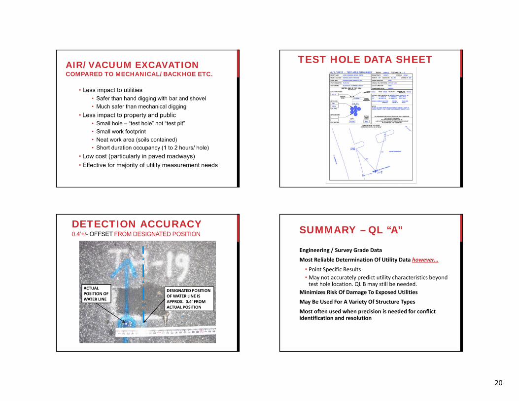
AIR/ VACUUM EXCAVATIONCOMPARED TO MECHANICAL/ BACKHOE ETC.
• Less impact to utilities • Safer than hand digging with bar and shovel• Much safer than mechanical digging
• Less impact to property and public• Small hole – “test hole” not “test pit”• Small work footprint• Neat work area (soils contained)• Short duration occupancy (1 to 2 hours/ hole)
• Low cost (particularly in paved roadways)• Effective for majority of utility measurement needs
TEST HOLE DATA SHEET
DETECTION ACCURACY0.4’+/- OFFSET FROM DESIGNATED POSITION
DESIGNATED POSITION OF WATER LINE IS APPROX. 0.4’ FROM ACTUAL POSITION
ACTUAL POSITION OF WATER LINE
SUMMARY – QL “A”
Engineering / Survey Grade Data
Most Reliable Determination Of Utility Data however…
• Point Specific Results • May not accurately predict utility characteristics beyond test hole location. QL B may still be needed.
Minimizes Risk Of Damage To Exposed Utilities
May Be Used For A Variety Of Structure Types
Most often used when precision is needed for conflict identification and resolution
21
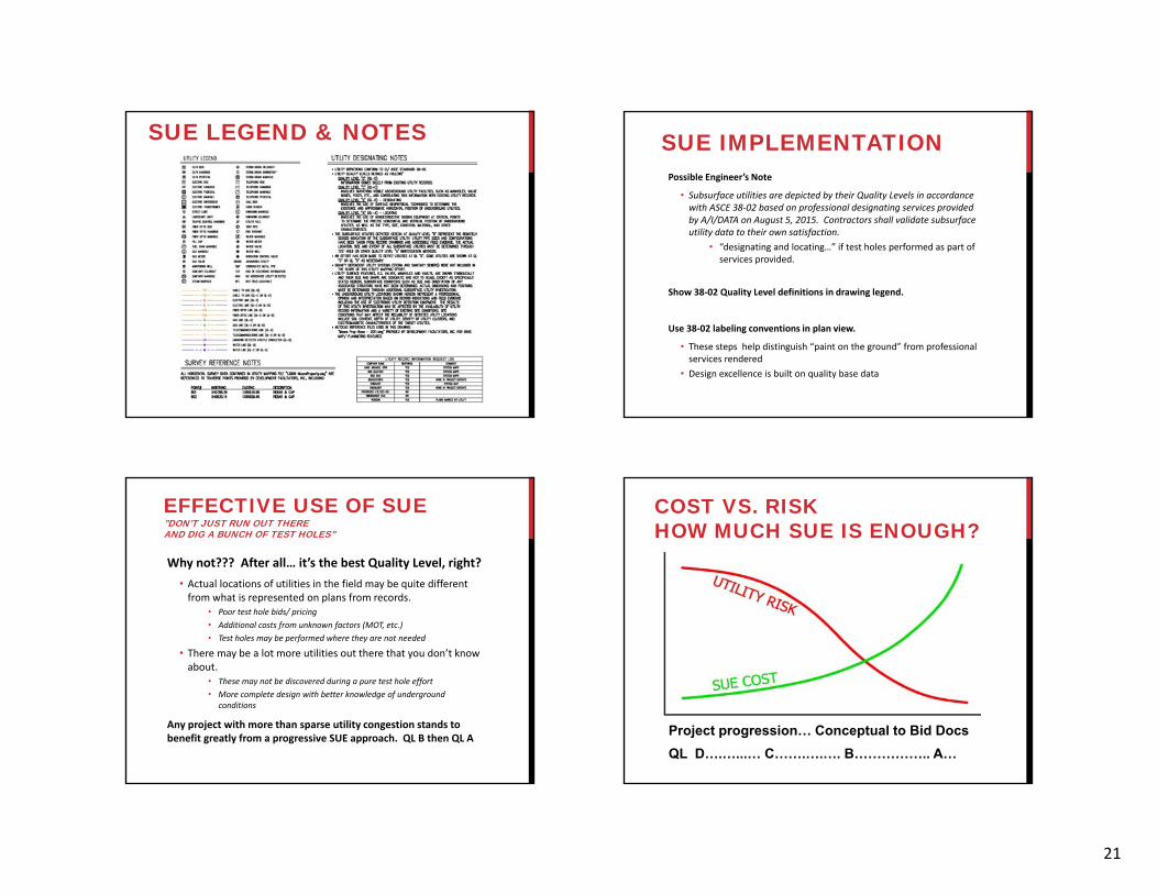
SUE LEGEND & NOTES SUE IMPLEMENTATIONPossible Engineer’s Note
• Subsurface utilities are depicted by their Quality Levels in accordance with ASCE 38‐02 based on professional designating services provided by A/I/DATA on August 5, 2015. Contractors shall validate subsurface utility data to their own satisfaction.
• “designating and locating…” if test holes performed as part of services provided.
Show 38‐02 Quality Level definitions in drawing legend.
Use 38‐02 labeling conventions in plan view.
• These steps help distinguish “paint on the ground” from professional services rendered
• Design excellence is built on quality base data
EFFECTIVE USE OF SUE”DON’T JUST RUN OUT THERE AND DIG A BUNCH OF TEST HOLES”
Why not??? After all… it’s the best Quality Level, right?• Actual locations of utilities in the field may be quite different from what is represented on plans from records.
• Poor test hole bids/ pricing• Additional costs from unknown factors (MOT, etc.)• Test holes may be performed where they are not needed
• There may be a lot more utilities out there that you don’t know about.
• These may not be discovered during a pure test hole effort• More complete design with better knowledge of underground
conditions
Any project with more than sparse utility congestion stands to benefit greatly from a progressive SUE approach. QL B then QL A
COST VS. RISKHOW MUCH SUE IS ENOUGH?
Project progression… Conceptual to Bid DocsQL D….…...… C…….….…. B…………….. A…

QUESTIONS?FHWA ‐
http://www.fhwa.dot.gov/programadmin/sueindex.cfmASCE ‐ http://www.asce.org/codes‐standards/list/
COMMON GROUND ALLIANCE http://www.commongroundalliance.com/UNDERGROUND CONSTRUCTION http://www.undergroundconstructionmagazine.com/UNDERGROUND FOCUShttp://www.underspace.com/
ACCURATE INFRASTRUCTURE DATA, INC.
1123 Hanzlik AvenueBaltimore, MD 21237888‐686‐5091 (TOLL FREE)410‐686‐5091 (PHONE)410‐686‐5093 (FAX)
[email protected]@aidatainc.com
THE END?


