Download - Steps to Selecting the Right Cable Enclosure
8
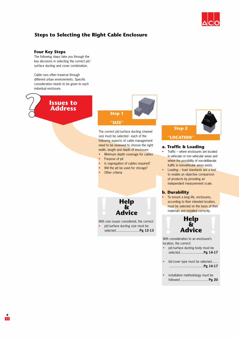
Four Key StepsThe following steps take you through the key decisions in selecting the correct pit/surface ducting and cover combination.
Cable runs often traverse through different urban environments. Specific consideration needs to be given to each individual enclosure.
Step 2
“LOCATION”
Help&
AdviceWith size issues considered, the correct:
pit/surface ducting size must be selected .........................Pg 12-13
The correct pit/surface ducting channel size must be selected - each of the following aspects of cable management need to be reviewed to choose the right width, length and depth of enclosure:
Minimum depth coverage for cablesPurpose of pit Is segregation of cables required?Will the pit be used for storage?Other criteria
Steps to Selecting the Right Cable Enclosure
Step 1
“SIZE”
Help&
AdviceWith consideration to an enclosure’s location, the correct:
pit/surface ducting body must be selected .........................Pg 14-17
lid/cover type must be selected ...... .....................................Pg 14-17
installation methodology must be followed .............................. Pg 20
Issues to Address
a. Traffic & Loading Traffic – where enclosures are located in vehicular or non vehicular areas and where the possibility of non-deliberate traffic in non-vehicular areas exists.Loading – load standards are a tool to enable an objective comparison of products by providing an independent measurement scale.
b. DurabilityTo ensure a long life, enclosures, according to their intended location, must be selected on the basis of their materials and installed correctly.
www.acoaus.com.au/cablemate
ACO CABLEMATE®
9
CorrectSelection
Step 3“SAFETY
& SECURITY”
With safety & security issues considered, the correct:
lid/cover type must be selected ...... .....................................Pg 18-19
installation methodology must be followed .........................Pg 18-19
maintenance procedures for authorised access must be established - consult client and/or regulatory body
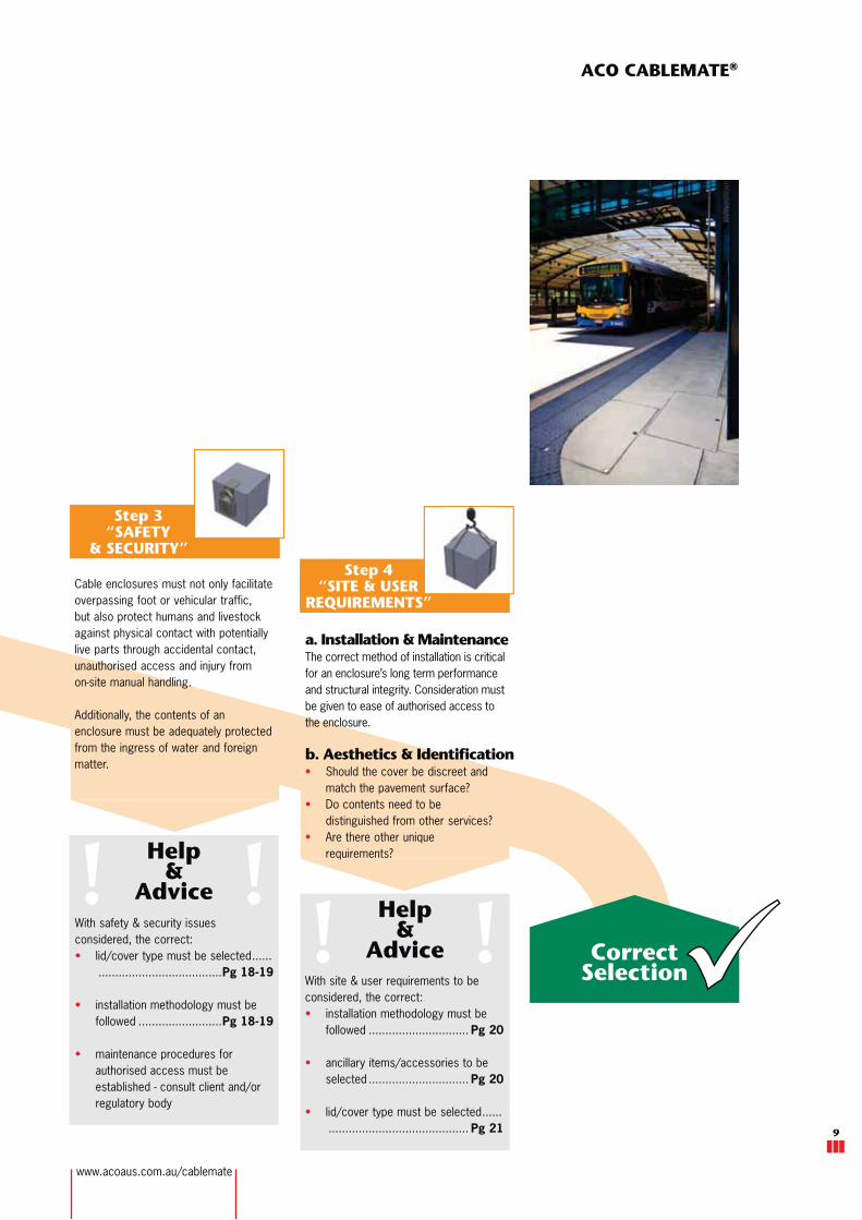
a. Installation & MaintenanceThe correct method of installation is critical for an enclosure’s long term performance and structural integrity. Consideration must be given to ease of authorised access to the enclosure.
b. Aesthetics & IdentificationShould the cover be discreet and match the pavement surface? Do contents need to be distinguished from other services?Are there other unique requirements?Help
&Advice
Help&
AdviceWith site & user requirements to be considered, the correct:
installation methodology must be followed .............................. Pg 20
ancillary items/accessories to be selected .............................. Pg 20
lid/cover type must be selected ...... .......................................... Pg 21
Cable enclosures must not only facilitate overpassing foot or vehicular traffic, but also protect humans and livestock against physical contact with potentially live parts through accidental contact, unauthorised access and injury from on-site manual handling.
Additionally, the contents of an enclosure must be adequately protected from the ingress of water and foreign matter.
Step 4“SITE & USER
REQUIREMENTS”

10
LANDSCAPE
A
HARDSCAPE
A - B
PAVEMENTS
BConfined areas exposed to foot traffic only. Plastic pits are suitable, as no accidental vehicular traffic is anticipated.
Paved areas exposed to general pedestrian thoroughfare traffic. Generally enclosures require discreet cover options.
Light duty pavements exposed to high volumes of foot traffic. Generally enclosures require footpath friendly lid options with slip resistance.
Typical Uses of Cable Enclosures
Discreet cover options
Footpath friendly lid options with slip resistance
Light duty landscaped applications
High security enclosures
General purpose surface ducting systems
This diagram shows typical applications where enclosures are used. Refer to page 8-9 when selecting the right cable enclosure for their intended application.
10
Application Type -See note pg 11 top
AS 3996 Load Class -

www.acoaus.com.au/cablemate
ACO CABLEMATE®
11
ROADS
B - D
HEAVY COMMERCIAL/INDUSTRIAL
E - F
INFRASTRUCTURE
GWhere possible, enclosures should be installed away from fast moving main road applications. On verges and traffic islands, where accidental vehicular traffic is anticipated, lids and covers must be locked into their enclosures. Ductile iron access cover systems are required for areas above class B.
Heavy vehicular and regularly trafficked areas require ductile iron access cover systems to be installed above rigid bodied pits.
Typical docks and aircraft pavements, where enclosures generally require a fully encased reinforced cement concrete encasement, for extreme loadings.
High security surface ducting systems
Access cover options for heavier duty applications
Heavy duty access covers with slip resistance
Heavy duty access cover options for extreme loadings
Note: The applications shown below are indicative only. It is the customer’s responsibility to determine/verify the
anticipated design loads for each application. Engineering advice may be necessary.
11

12
To meet an enclosure’s functional requirements, correct pit/ducting channel sizing is critical to allow an acceptable working area or free space. This is to maintain the mechanical protection of cables and the uninterrupted continuity (depth & direction) of the cable route.
Undersized enclosures can result in damaged cables and possible hazards to utility workers and the general public.
To ensure a correctly sized enclosure is selected, refer to the product pages in this catalogue where the clear working area within the pit or ducting channel is illustrated. This is the free space inside the enclosure (without obstruction). Note: most cable pits have tapered walls.
Clear working area of pits
Other specific factors include:
Depth of Cables
For safety, cables need to be installed to the minimum depth of cover and protection governed by AS/NZS 3000 and HB 29. The type of cables, their communal location (e.g. footpaths as opposed to parks) and the nature of the overlying pavement/slab are important determinants. AS/ACIF S009 specifies cable depth requirements for larger maintenance (or access) holes. All enclosures must be deep enough to cater for these depths.
Change of Direction
Enclosures must be sized large enough so that when cable routes change direction, minimum allowable radii specified by the cable manufacturer are adhered to. If this information is not available, consult AS/NZS 3000 & HB 29, or contact ACO. To ensure the bending radius is maintained, HB 29 recommends communications cables are to be anchored immediately before and after a bend (not at a bend in a pit).
Jointing
AS/NZS 3000 defines a number of connection methods for joining cables. These joints are generally housed in cable pits to protect them from undue mechanical stresses. Pits must be sized adequately to accommodate the type of connector chosen for the enclosure.
Drawing
When drawing (pulling/hauling) cables through a cable pit, care must be taken to ensure the cable is not damaged. AS/NZS 2053.1 & AS/NZS 3084 specifies the requirements for correct conduit preparation applicable at pit/conduit interfaces.
A correctly sized pit will allow for an adequate working area for the cable drawing operation. Various communications carriers and HB 29 also offer guidelines to assist with this practice.
On occasions, bellmouth fittings may be required to ensure no damage occurs to cables during cable drawing. Unlike other materials used in cable pits, polymer concrete can be ground to a smooth edge which will not damage cables.
1. Size
There are a number of factors that determine the size of a cable enclosure. AS/NZS 3000 and AS/NZS 3084 stipulate the criteria governing the number and size of conduits in these spaces.
L W
DZ
B A
Y X

www.acoaus.com.au/cablemate
ACO CABLEMATE®
13
Segregation
On occasions, enclosures need to be large enough to be divided into different sub-enclosures to preserve the segregation of heterogeneous cables. Occasionally, these can comprise a mix of low voltage power cables, communications cables, pipes supplying gas and water etc.
AS/ACIF S008 sets out the conditions for segregation and clearances in enclosures specifically for communications cables with low voltage power cables whilst AS/NZS 3000 & HB 29 gives general guidance for the arrangement of cables in trenches. Larger maintenance (or access) holes and cable trunking systems may contain high voltage cables. Segregation and separation conditions for these applications are detailed in AS/ACIF S009.
Segregation in a cable pit can be achieved by installing a dividing wall. ACO manufactures a bracket (part no. 76514) which can be attached to a polymer concrete pit by means of nuts and bolts. A divider should be cut from 15mm thick wood, plastic or other suitable material and fitted into the bracket’s angles to provide an internal wall. All compartments need to be waterproofed from other compartments, therefore the divider would need to be sealed with a suitable sealant. Additional drainage holes may be required within each compartment of the pit.
ACO does not recommend plastic pits for these applications, as wall distortion together with the pit’s side ribbing profile, would make sealing of dividers difficult.
For surface cable ducting applications, ACO can provide permanent cable separation with the provision of cable spacers.
Storage
Cable storage pits are enclosures used for any of the above purposes but are large enough to store equipment and/or additional cabling for future cable route expansion. Cable pits must be sized accordingly.
Cable spacer

14
(a) Traffic & Loading
When selecting an enclosure type, designers and end users must determine if the enclosure will be placed in a trafficable application; whether the traffic is deliberate (e.g. along a driveway) or accidental (e.g. along a footpath); and whether the traffic is of a vehicular or pedestrian nature. In addition to this, consideration must be given to ground topography, soil conditions, and building location.
Pits positioned along a long cable route can typically cross various types of load scenarios. Each pit location should be individually considered.
Non Vehicular Pavements
Footpaths
Enclosures located in footpaths are generally exposed to a high volume of pedestrian traffic but can also be subjected to non deliberate vehicular loads. Good practice requires that enclosures are selected so that only a minimal surface area of a footpath space is occupied, particularly along cycleways, pedestrian alignments, wheelchair access paths or ramps. It is also recommended that cable pits are located outside the ‘drip lines’ of footpath vegetation.
Landscaped Areas
Enclosures installed in landscaped areas are generally exposed only to pedestrian traffic. Plastic pits are ideal for this application as long as the sand or soil is stable and vehicles in close proximity to them do not surcharge the soil and introduce side loads to each pit.
Designers must also aim to locate cable enclosures at high points along a terrain so that they do not become significant drainage collection points.
Vehicular Pavements
Cable enclosures located in rigid pavements (e.g. vehicle paths, driveways, cycleways, ramps) are generally subjected to deliberate vehicular traffic. Pit bodies need to be strong enough to support the traffic rated covers bearing the loads and be encased in cement concrete (base and surround). ACO does not recommend the use of plastic pits in these applications.
For these applications, AS/NZS 3084 specifies minimum distances for access holes with respect to each other, roadway corners and other highly trafficked zones.
Unless enclosures are designed for heavy duty applications, they must not be placed in locations where heavy loading is anticipated. Guards or barriers that prevent entry of this type of traffic are recommended. If a heavy duty cable pit is required or where constant deliberate vehicular traffic is anticipated, ACO recommends Rhinocast®, ductile iron access covers to be installed in the slab/pavement above the enclosure or ACO’s CS System, if surface cable ducting is required.
Designers should avoid locating cable pits in fast moving road applications unless certified by a qualified engineer and approved by the relevant roads authority. Austroads document: AP-G72 provides further guidelines for cable pits and access holes to be located on or near urban or rural roads.
2. Location
www.acoaus.com.au/cablemate
ACO CABLEMATE®
15
Modular surface ducting systems - dependent on cover/type/size
Load Class A
15kN
Load Class B
125kN
Load Class C
250kN
Load Class D
400kN
Load Class E
600kN
Load Class F
900kN
Load Class
A10kN
Extra light duty
Load Class
B80kN
Light duty
Load Class
C150kN
Medium duty
Load Class
D210kN
Heavy duty
Load Class
E400kN
Extra heavy duty
Load Class
F600kN
Extra heavy duty
Load Class
G900kN
Extra heavy duty
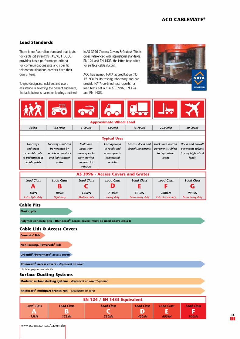
AS 3996 - Access Covers and Grates
Approximate Wheel Load
330kg 2,670kg 5,000kg 8,000kg 13,700kg 20,000kg 30,000kg
Plastic pits
Polymer concrete pits - Rhinocast® access covers must be used above class B
Non-locking/PowerLok® lids
Rhinocast® access covers - dependent on cover
Concrete1 lids
Rhinocast® multipart trench run - dependent on cover
Load Standards
There is no Australian standard that tests for cable pit strengths. AS/ACIF S008 provides basic performance criteria for communications pits and specific telecommunications carriers have their own criteria.
To give designers, installers and users assistance in selecting the correct enclosure, the table below is based on loadings outlined
in AS 3996 (Access Covers & Grates). This is cross referenced with international standards, EN 124 and EN 1433, the latter, best suited for surface cable ducting.
ACO has gained NATA accreditation (No. 15193) for its testing laboratory and can provide NATA certified test reports for load tests set out in AS 3996, EN 124 and EN 1433.
Cable Lids & Access Covers
Surface Ducting Systems
Cable Pits
Typical Uses
Footways
and areas
accessible only
to pedestrians &
pedal cyclists
Footways that can
be mounted by
vehicle or livestock
and light tractor
paths
Malls and
pedestrian
areas open to
slow moving
commercial
vehicles
Carriageways
of roads and
areas open to
commercial
vehicles
General docks and
aircraft pavements
Docks and aircraft
pavements subject
to high wheel
loads
Docks and aircraft
pavements subject
to very high wheel
loads
EN 124 / EN 1433 Equivalent
Urbanfil®/Pavermate® access covers
1. Includes polymer concrete lids

16
2. Location
(b) Durability - Material Properties
Different materials for components used in enclosures exhibit different physical and mechanical properties which may affect performance life cycle.
Cable pit bodies are typically made from moulded plastic, concrete or polymer concrete. Other materials e.g. fibreglass or aluminium are used for very specific applications.
Polymer Concrete (Polycrete®)
Polymer concrete is produced by mixing mineral aggregates with a resin binding agent.
The resulting enclosure and its components are smooth and of high quality as they are made with matched surface tooling for consistent quality. The pits are lightweight and easy to handle ensuring cost effective installations. Although having thinner side walls, properly designed polymer concrete cable pits are strong, durable and possess mechanical properties typical of bulkier concrete enclosures. They can also be cut with masonry drills and grinders.
Polymer concrete pits provide excellent electrical insulation because castings are homogenous (do not contain steel reinforcing) and there are no macroscopic voids (moisture traps).
The material is non porous and offers a much higher resistance to chemical, weathering and biological attack than concrete, ensuring pits have a superior life cycle.
Cement Concrete
Precast concrete is occasionally used for small cable enclosures. However, large maintenance holes are generally cast-in-situ. Precast concrete pits require thick walls to provide their structural integrity and are therefore heavy, cumbersome and difficult to transport. Higher installation costs must also be considered as cranes or other special equipment may be required on site. Cement concrete is typically a porous material and can
Lids & Access Covers
Pit lids and/or access covers are available in precast concrete, polymer concrete, composite, steel and aluminium. Cast iron and steel are used in the manufacture of access covers.
Precast concrete and polymer concrete lids are not recommended for vehicular applications whilst steel and cast (ductile) iron covers have higher tensile strengths and are best suited for wheel loads.
For optimum corrosion resistance, ACO recommends steel access covers and lids are hot dip galvanised to AS 4680.
Effect of Fire on Pits
Polymer concrete is a self extinguishing material which does not give off toxicor any other dangerous fumes.
Plastics are combustible. They will burn and disintegrate when subject to high temperature.
In areas which have been subjected to fire, particular care should be taken in respect to pit covers. Cement concrete and polymer concrete will lose their structural integrity and should nothave loads applied to them.
Steel & cast iron covers may keep their strength but their seating may be damaged and subject to collapse.
absorb up to 9% water by weight. In aggressive environments, it is also prone to deterioration, particularly in alkaline soils. Therefore, concrete enclosures require regular maintenance and in some cases are susceptible to early failure.
Glass Reinforced Concrete
Glass reinforced concrete (GRC) is sometimes used in the manufacture of precast pits. GRC is a mixture of cement, fine aggregate, water, chemical admixtures, glass fibres and is considered porous.
Plastic
Plastic cable pits are generally injection or rotational moulded and can offer an effective economic solution for light duty applications.
Product design can be used to overcome some of the mechanical weaknesses inherent to plastic. Walls are typically designed with ribs for increased strength but side walls are often still flexible and will distort when placed in unstable soils or load bearing applications.
ACO’s plastic pits have straight sidewalls with moulded continuous ribs for the efficient transfer of loads without causing additional stresses to the structure. ACO’s plastic pits have undergone a finite element analysis (FEA) to ensure the most effective design for their intended use. Pits have also been physically tested in
an independent test laboratory.
FEA moulded designs

www.acoaus.com.au/cablemate
ACO CABLEMATE®
17
Mechanical PropertiesCement Concrete
Polymer Concrete GRC Plastic
Compressive strength
The enclosure’s wall/base is subject to compressive
loads in use and needs to withstand specified loads.25MPa 96MPa C-579 50MPa 58MPa D-695
Flexural strength
Affects site handling and when enclosure is installed
in areas where encasement and soils are suspect. 3MPa 27MPa C-580 12MPa 15MPa D-790
Tensile strength
Generally only relevant to an enclosure’s lid/cover. 2MPa 21MPa C-307 5.5MPa 14MPa D-638
Thermal/Electrical PropertiesWater absorption
The enclosure’s wall/base is designed to keep
moisture away from it’s contents where possible.<3% +0.07% C-97 12% +0.31% D-570
Electrical resistivity
The electrical insulation capability of an enclosure’s
materials. 1 x 10⁸ �/sq 1 x 10⁸ �/sq 1 x 10⁸ �/sq 1 x 10¹⁶ �/sq
Freeze-thaw
Inability to withstand freeze-thaw cycles causes
surface spoiling and leads ultimately to an
enclosure’s failure.
300 cycles maintain
80% structural
integrity
300 cycles
modulus of elasticity
95.1% C666
modulus of elasticity
unchanged
223 cycles
FAILED modulus of
elasticity test C666
Coefficient of expansion/contraction
Excessive movement between enclosure’s wall/base
and encasement materials (usually concrete) creates
unwanted stresses which may lead to failure.
11.7 x 10⁻⁶ per oC 19.8 x 10⁻⁶ per oC
D696
20 x 10-6 per oC 97.2 x 10⁻⁶ per oC
D696
Water vapour transmission
WVT is a measurement of water vapour flow
through a material. Passage of water vapour may
be critical in some instances.
See water
absorption test
WVT - 0.0364g/m2 -
1,592hrs
E96
1 x 10⁻⁴ gm/s.MN
WVT - 0.1392g/m2
1,592hrs
E96
Surface PropertiesSurface burning
Cable enclosures are often used around petrol
stations, chemical processing and interior
applications and may be subject to fire. They
should be non-flammable and not give off fumes
or smoke.
Non-combustible
Flame spread : 0
Smoke density : 5
E84
Non combustible
Ignitability: P
Fire propagation: 0
Flame spread : 1
BS476
Flammable
Weathering
The majority of cable enclosures are used in
exterior applications. Ability to withstand adverse
weather will ensure long service life (erosion, UV
degradation etc).
Good depending
upon proper curing
2000hr exposure no
change G-153
Similar to cement
concrete. UV stable
1000hr exposure
no change G-154
FAILED TEST
Chemical resistance
Cable enclosures may be subject to acidic or
alkaline soils.Poor Good
Poor - better than
cement concreteGood
Colour Key: - Good - Acceptable - Poor
Cement concrete values obtained from AS 3600 and SA HB64 Guide to Concrete Construction (Cement & Concrete Assoc. of Australia)
Polymer concrete values obtained from experimental data using ASTM testing procedures
GRC values obtained from Design, Manufacture & Installation of Glass Reinforced Concrete (GRC Industry Group of NPCAA)
Plastic values obtained from experimental data using ASTM testing procedures
Electrical resistivity test based upon experimental data conducted by University of NSW

Page | 1
ACO Comparison sheet - Polycrete® Pits v. GRC pits [Cable pits]
Polycrete Pits from the ACO Cablemate range are manufactured from polymer concrete. Polymer concrete is
produced by mixing mineral aggregates with a resin binding agent.
Glass reinforced concrete (GRC), although mainly used in exterior building façade panels and as architectural
precast concrete, is sometimes used in the manufacture of precast pits. GRC is a mixture of cement, fine
aggregate, water, chemical admixtures, and glass fibres.
Both types of pits are lightweight ensuring cost effective installations. For vehicular load bearing applications, if a
cover & frame system (access cover) is required above a pit; the frame needs to be adequately concrete
encased (an example is shown, overleaf). Beware of manufacturers recommendations that state otherwise.
There are significant differences between Polycrete Pits and GRC pits.
Onsite fabrications and handling
Polycrete Pits can be easily cut with masonry drills, holesaws and grinders. The smooth walls allow
for easy fastening of brackets and other cable accessories. There are also standard pipe cable entry
plastic inserts for ease of creating a conduit connection.
In contrast GRC pits contain rough walls which are more difficult to work with. In addition to this, GRC
will have abrasive edges and may have fibres protruding from the surface which could cause skin
irritation or abrasions.
Strength
Polycrete Pits are purpose designed to be strong. They possess almost twice the compressive
strength and more than twice the flexural strength of GRC pits. Polycrete Pits also have almost 4
times the tensile strength of GRC pits.
Mechanical Properties Cement Concrete Polymer Concrete GRC HDPE
Compressive strength
The trench body is subject to
compressive loads in use and
needs to withstand the
specified load.
25MPa 96MPa C-579 50MPa 58MPa D-695
Flexural strength
Affects site handling and when
trench body is in areas where
encasement and soils are
suspect.
3MPa 27MPa C-580 12MPa 15MPa D-790
Tensile strength
Not generally required in
trench bodies, but relevant to
grates. Used as material
measurement.
2MPa 21MPa C-307 5.5MPa 14MPa D-638
Page | 2
Porosity & electrical resistivity
Compared with GRC pits, Polycrete Pits have an extremely low porosity (0.07% v. 12%-GRC). This is
important in cable pits where water ingress needs to be addressed to keep the pit contents dry. GRC
pits are also prone to moisture traps (large voids) which may reduce the pit’s electrical insulation.
Chemical resistance
Due to the resin binding agent used, Polycrete Pits offer a higher resistance to chemical, weathering
and biological attack than GRC, ensuring pits have a superior life cycle. In aggressive environments,
GRC is prone to deterioration, particularly in alkaline soils. Therefore, GRC pits require regular
maintenance and in some cases are susceptible to early failure.
Quality & maintenance
Polycrete Pits have smooth high quality walls. Modular components come from matched precision
tooling for consistent quality. In contrast, GRC pits have rough walls of inconsistent quality.
In the external environment Polycrete Pits are unaffected by biological attack i.e. there is no need to
continuously remove vegetation which may otherwise grow on concrete based products such as GRC.
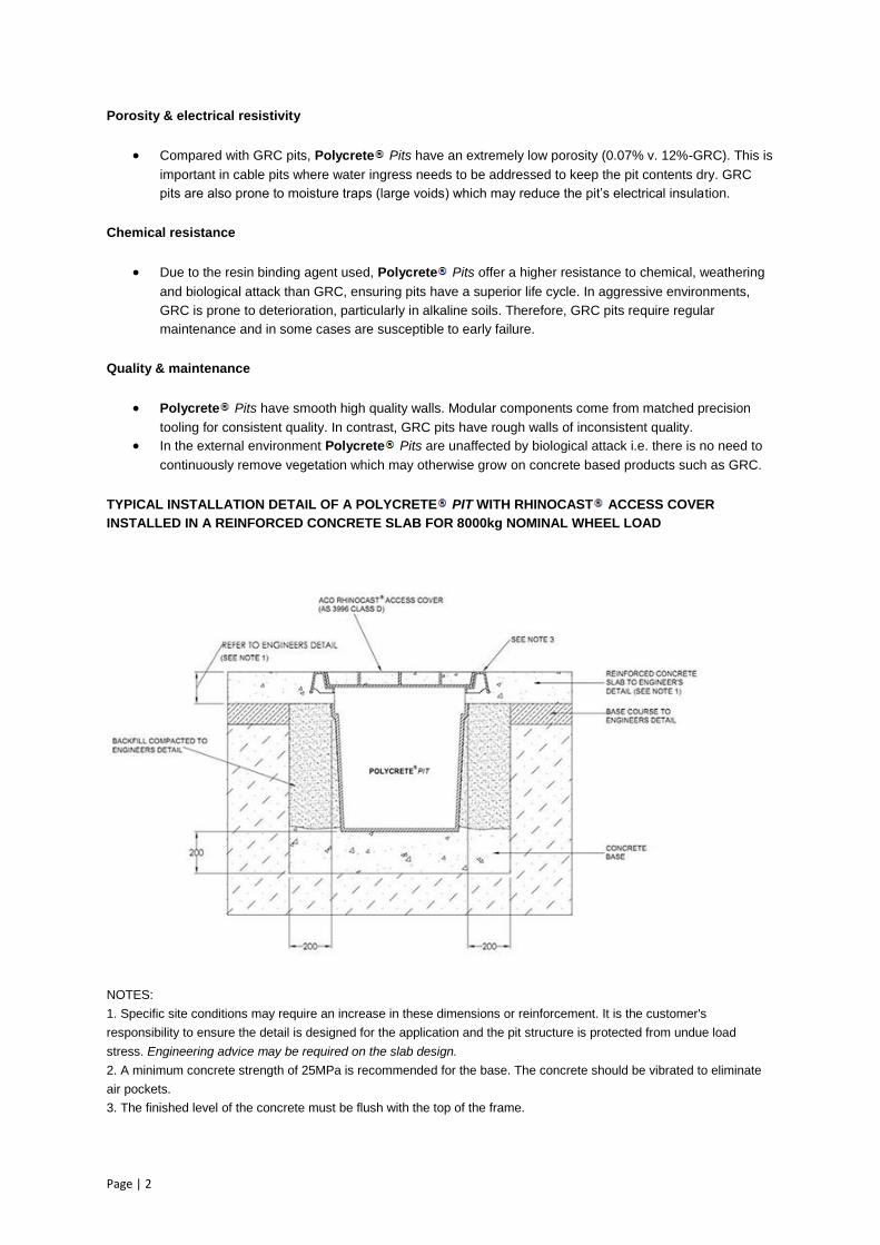
TYPICAL INSTALLATION DETAIL OF A POLYCRETE PIT WITH RHINOCAST ACCESS COVER
INSTALLED IN A REINFORCED CONCRETE SLAB FOR 8000kg NOMINAL WHEEL LOAD
NOTES:
1. Specific site conditions may require an increase in these dimensions or reinforcement. It is the customer's
responsibility to ensure the detail is designed for the application and the pit structure is protected from undue load
stress. Engineering advice may be required on the slab design.
2. A minimum concrete strength of 25MPa is recommended for the base. The concrete should be vibrated to eliminate
air pockets.
3. The finished level of the concrete must be flush with the top of the frame.
18
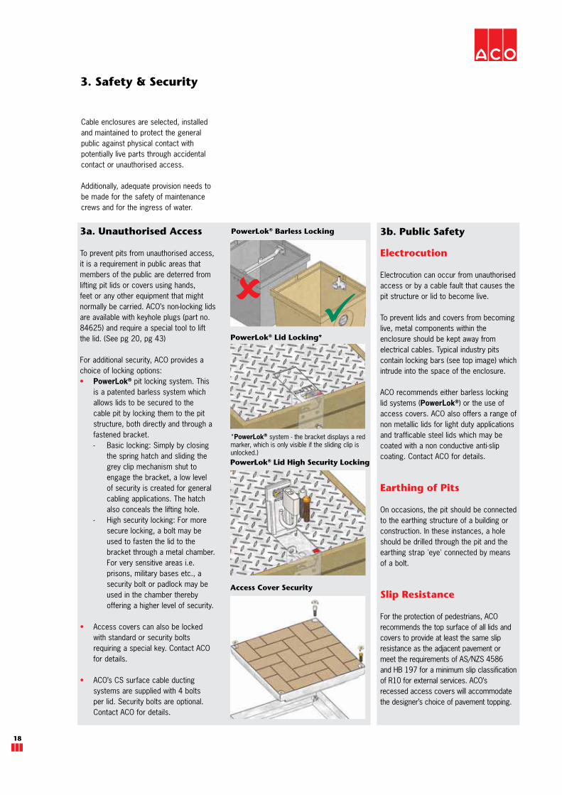
PowerLok® Barless Locking3a. Unauthorised Access
To prevent pits from unauthorised access, it is a requirement in public areas that members of the public are deterred from lifting pit lids or covers using hands, feet or any other equipment that might normally be carried. ACO’s non-locking lids are available with keyhole plugs (part no. 84625) and require a special tool to lift the lid. (See pg 20, pg 43)
For additional security, ACO provides a choice of locking options:
PowerLok® pit locking system. This is a patented barless system which allows lids to be secured to the cable pit by locking them to the pit structure, both directly and through a fastened bracket. - Basic locking: Simply by closing
the spring hatch and sliding the grey clip mechanism shut to engage the bracket, a low level of security is created for general cabling applications. The hatch also conceals the lifting hole.
- High security locking: For more secure locking, a bolt may be used to fasten the lid to the bracket through a metal chamber. For very sensitive areas i.e. prisons, military bases etc., a security bolt or padlock may be used in the chamber thereby offering a higher level of security.
Access covers can also be locked with standard or security bolts requiring a special key. Contact ACO for details.
ACO’s CS surface cable ducting systems are supplied with 4 bolts per lid. Security bolts are optional. Contact ACO for details.
3b. Public Safety
Electrocution
Electrocution can occur from unauthorised access or by a cable fault that causes the pit structure or lid to become live.
To prevent lids and covers from becoming live, metal components within the enclosure should be kept away from electrical cables. Typical industry pits contain locking bars (see top image) which intrude into the space of the enclosure.
ACO recommends either barless locking lid systems (PowerLok®) or the use of access covers. ACO also offers a range of non metallic lids for light duty applications and trafficable steel lids which may be coated with a non conductive anti-slip coating. Contact ACO for details.
Earthing of Pits
On occasions, the pit should be connected to the earthing structure of a building or construction. In these instances, a hole should be drilled through the pit and the earthing strap 'eye' connected by means of a bolt.
Slip Resistance
For the protection of pedestrians, ACO recommends the top surface of all lids and covers to provide at least the same slip resistance as the adjacent pavement or meet the requirements of AS/NZS 4586and HB 197 for a minimum slip classification of R10 for external services. ACO’s recessed access covers will accommodate the designer’s choice of pavement topping.
PowerLok® Lid High Security Locking
PowerLok® Lid Locking*
3. Safety & Security
Cable enclosures are selected, installed and maintained to protect the general public against physical contact with potentially live parts through accidental contact or unauthorised access.
Additionally, adequate provision needs to be made for the safety of maintenance crews and for the ingress of water.
Access Cover Security
*PowerLok® system - the bracket displays a red marker, which is only visible if the sliding clip is unlocked.)

www.acoaus.com.au/cablemate
ACO CABLEMATE®
19
3c. Worker Safety
For maintenance operations, some basic precautions should be exercised.
Field maintenance crews trained to service communication pits should not perform any work on pits suspected of containing unprotected electrical cables, terminations or joints (whether sealed or not). Only specialist authorised electrical crews should carry out work on electrical pits.
Ingress of Foreign Matter
A cable enclosure must provide reasonable protection against damage from environmental and other external influences. Typically this includes exposure to weather (UV and water), flora, fauna, galvanic action and the accumulation of dust.
Excessive ingress of any, or a combination of the above factors, may make cable enclosures hazardous as well as causing damage to their contents.
The degree of protection provided by a lid or access cover against the ingress of water or foreign objects, (needles, fingers etc) is expressed as an IP (International Protection) rating, in accordance with AS 60529. AS/NZS 2053.1 applies this to all conduits and fittings and AS/ACIF S008 applies this specifically to communications enclosures.
Field maintenance crews should always check for the presence of hidden hazards such as dangerous gases, reptiles, insects or sharp objects.
Needle Safety
In certain areas of high drug use, hypodermic needles can be disposed of by pushing the needle through the lifting keyhole of the cover into the pit below. If this is a concern, ACO recommends an access cover. Alternatively, ACO’s steel lids are fitted with syringe guards and plugs are available for all non-locking lids. Additionally, PowerLok® lids are designed with concealed keyholes. All ACO’s lids and covers meet up to IP4X, AS 60529, if keyhole plugs are used. Contact ACO for specific IP ratings and definitions for each lid/cover.
3d. Water
Weather Resistance
AS/NZS 3000 requires enclosures that are exposed to weather, provide protection by ‘adequate means’. Contractors can improve the protection of cables against ingress of moisture and termite attack. HB 29 provides details with respect to communication cables.
Entry holes for conduits should be capable of being sealed to prevent siltation. Cable jointing pits should contain connectors that are suitably selected, enclosed, positioned and supported to prevent ingress of dust or moisture.
Cable enclosures are not designed to be waterproof. A reasonable degree of weather resistance can be achieved by sealing edges of covers and lifting holes each time the cover is removed for servicing. ACO, however recommend Rhinocast® access covers are used to meet the gas & water tightness requirements of AS 3996. For further information on ensuring weather resistance of enclosures, contact ACO.
Ponding
Pit drainage is recommended particularly for pits positioned at sag points. See pg 80.
It is extremely hazardous to reach into a pit to handle cables if it is filled with water, particularly if the enclosure houses electrical cables and joints. It should be noted that pits with superior electrical insulation properties such as plastic and polymer concrete can hold water which may be live despite the surrounding earth/pavement appearing inert and safe. HB 29 recommends the use of non conductive snags to lift communications cables and connectors out of the water if drainage of the pit is not practical.
Manual Handling
The National Code of Practice for Manual Handling recommends a maximum unassisted lifting weight of 55kg. However, it highlights that as weight increases from 16kg to 55kg, safety of individuals doing the lifting is compromised.*
ACO’s steel lids do not exceed a lifting weight of 25kg, meeting the requirements of regulatory authorities for steel lids. ACO also offer a range of lid lifters and a NATA certified pit lifter to facilitate installation and maintenance (pg 43). Product lifting weights are also specified in this catalogue.
* Certain regulatory authorities, states and carriers
may have their own criteria.

20
4. Site and User requirements
On occasions a bar(s) is/are required to hang a joint or fuse inside an electrical pit. ACO’s plastic pits have moulded sockets in the walls to hang either a 40mm diameter plastic or metal tube across the pit.
Where hangers are required on a polymer concrete pit, ACO manufactures a bracket (part no. 76509) which can be attached to pit walls in the appropriate positions to support the 40mm diameter bar.
Multiple conduit entry points to the pit should be via correctly sized holes to minimise the amount of pit wall removed. ACO offers a range of holesaws (pg 43) to facilitate this operation.
Cable and Joint Hangers
4a. Installation
Encasement
Correct installation is critical for long term performance and structural integrity. See pg 79 for installation methodology.
In load applications, a correctly installed cable enclosure involves proper in situ encasement. ACO recommends a minimum grade 25MPa correctly sized concrete surround. A hole larger than the external size of the cable pit/channel duct must be excavated to accommodate this. See pg 82 for ACO’s recommended excavation guidelines.
Plastic moulded pits are recommended only in landscaped applications. All cable pits must be installed according to the minimum cement concrete dimensions shown on pg 84. These dimensions are based on average ground conditions.
Specific site conditions may require an increase in these dimensions or reinforcement. Engineering advice may be necessary for certain applications and all installations should conform to accepted building standards and as directed by relevant authority inspectors.
Multiple Conduit Entry
There is a restriction on the number of conduits that can be connected to a pit. Care must be taken that the pit’s structural integrity is not compromised by removing excessive pit wall area, particularly in trafficable applications. To spread loads transmitted through the pit structure, ACO recommends concrete haunching around conduits to prevent pit collapse.
4b. Access
All cable pit covers can be removed by means of the Australian Standards (AS 3996) lifting keys or in the case of cement concrete lids, the industry standard communications key is required. To lock/unlock the metal hatch of the PowerLok® lid, a PowerLok® tool (part no. 01318) is required or a wide bladed screw driver.
A full range of accessories for the installation and maintenance of ACO’s cable enclosures is listed on pg 43.
www.acoaus.com.au/cablemate
ACO CABLEMATE®
21
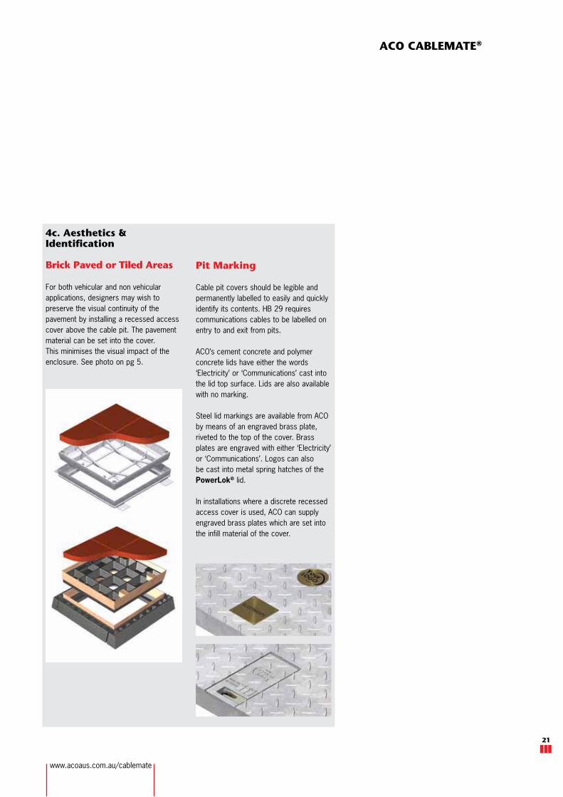
4c. Aesthetics & Identification
Brick Paved or Tiled Areas For both vehicular and non vehicular applications, designers may wish to preserve the visual continuity of the pavement by installing a recessed access cover above the cable pit. The pavement material can be set into the cover. This minimises the visual impact of the enclosure. See photo on pg 5.
Pit Marking
Cable pit covers should be legible and permanently labelled to easily and quickly identify its contents. HB 29 requires communications cables to be labelled on entry to and exit from pits.
ACO’s cement concrete and polymer concrete lids have either the words ‘Electricity’ or ‘Communications’ cast into the lid top surface. Lids are also available with no marking.
Steel lid markings are available from ACO by means of an engraved brass plate, riveted to the top of the cover. Brass plates are engraved with either ‘Electricity’ or ‘Communications’. Logos can also be cast into metal spring hatches of the PowerLok® lid.
In installations where a discrete recessed access cover is used, ACO can supply engraved brass plates which are set into the infill material of the cover.


