SHAKER STEP-STOOL Prepared by: Harry Hawkins
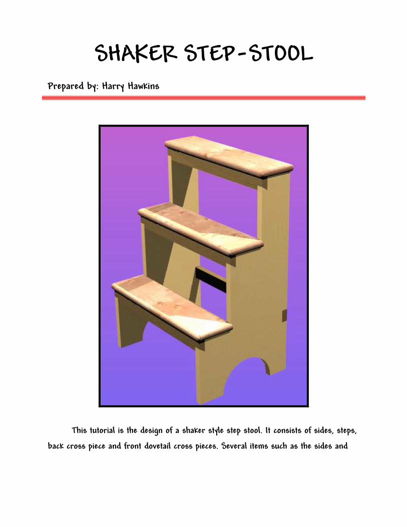
This tutorial is the design of a shaker style step stool. It consists of sides, steps,
back cross piece and front dovetail cross pieces. Several items such as the sides and
© Harry Hawkins 2005 Page 2 Pro/DESKTOP Tutorial
bottom and middle steps need only be designed once since they will be used more than
once in the final assembly.
When you open Pro/DESKTOP, set the Options, Units to inches. It is expected
that you already know how to move between orthographic and pictorial views and have a
reasonable amount of skill in using the mouse.
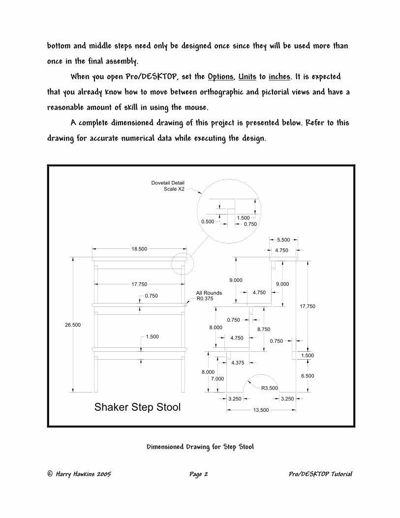
A complete dimensioned drawing of this project is presented below. Refer to this
drawing for accurate numerical data while executing the design.
Dovetail Detail
Scale X2
18.500
Shaker Step Stool
17.750
0.750
26.500
1.500
17.750
R0.375
9.000
8.750
R3.500
13.500
7.000
8.000
3.250
4.750
4.375
8.000
0.750
6.500
3.250
1.500
0.750
4.750
9.000
All Rounds
0.5001.500
0.750
5.500
4.750
Dimensioned Drawing for Step Stool
© Harry Hawkins 2005 Page 3 Pro/DESKTOP Tutorial
Knowledge or information you should know prior to beginning
this tutorial: ���� Navigate in Windows ���� Create, save, rename and delete
folders and files ���� Mouse commands – right and
left click and mouse wheel ���� Basic Pro/DESKTOP sketching
tools – lines, circles etc. ���� Pro/D Workplanes and sketches.
What you should learn from completing this tutorial:
���� Create sketches ���� Draw valid profiles ���� Extrude profiles ���� Rounding Edges ���� Assembly ���� Alignment, Centering Axis and
Mating
.
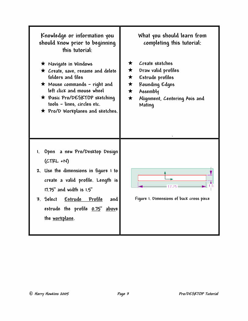
1. Open a new Pro/Desktop Design
(CTRL +N)
2. Use the dimensions in figure 1 to
create a valid profile. Length is
17.75” and width is 1.5”
3. Select Extrude Profile and
extrude the profile 0.75” above
the workplane.
Figure 1. Dimensions of back cross piece
© Harry Hawkins 2005 Page 4 Pro/DESKTOP Tutorial
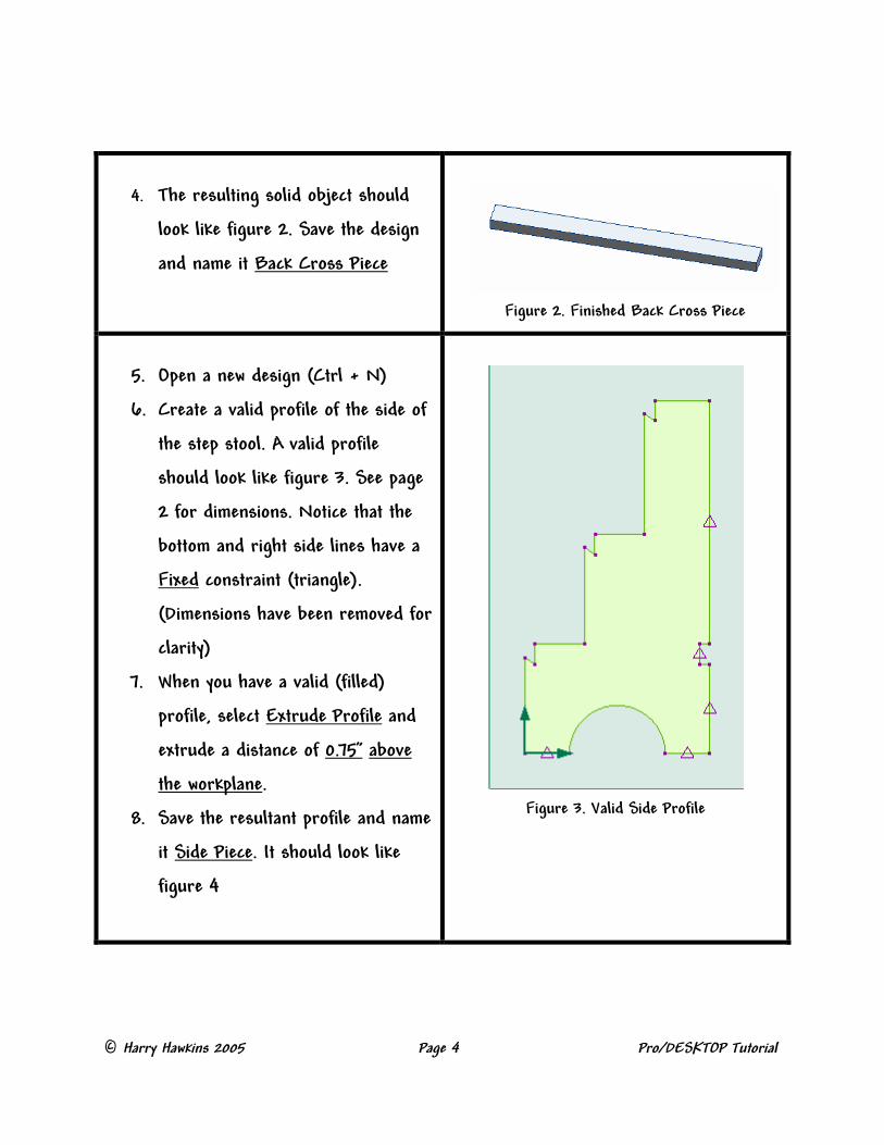
4. The resulting solid object should
look like figure 2. Save the design
and name it Back Cross Piece
Figure 2. Finished Back Cross Piece
5. Open a new design (Ctrl + N)
6. Create a valid profile of the side of
the step stool. A valid profile
should look like figure 3. See page
2 for dimensions. Notice that the
bottom and right side lines have a
Fixed constraint (triangle).
(Dimensions have been removed for
clarity)
7. When you have a valid (filled)
profile, select Extrude Profile and
extrude a distance of 0.75” above
the workplane.
8. Save the resultant profile and name
it Side Piece. It should look like
figure 4
Figure 3. Valid Side Profile
© Harry Hawkins 2005 Page 5 Pro/DESKTOP Tutorial
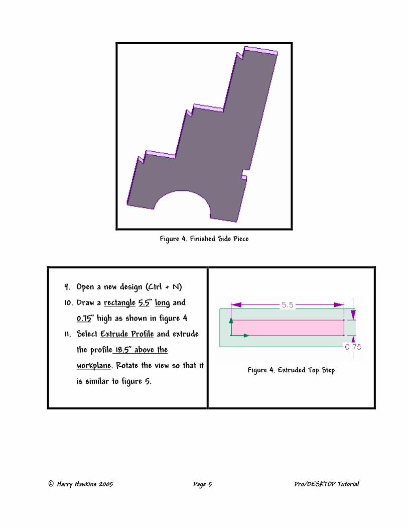
Figure 4. Finished Side Piece
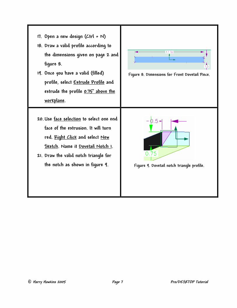
9. Open a new design (Ctrl + N)
10. Draw a rectangle 5.5” long and
0.75” high as shown in figure 4
11. Select Extrude Profile and extrude
the profile 18.5” above the
workplane. Rotate the view so that it
is similar to figure 5.
Figure 4. Extruded Top Step

© Harry Hawkins 2005 Page 6 Pro/DESKTOP Tutorial
12. Use Face Selection to select
either the Top or Bottom face. The
face will turn red.
13. With the face selected, right click
and select Round Edges.
Figure 5. Extruded Top Step
14. Figure 6 shows the top face
selected and the Round Edges
dialog box correctly filled for a
0.375” round. Notice the yellow trial
view in the background. Click OK to
complete the rounds.
Figure 6. Top Face selected for rounding.
15. Rotate the image and select the
bottom face. Right Click and select
Round Edges. Set the radius to
0.375” and click OK to complete the
round.
16. The image should look like figure 7.
Save it and name it Top Step.
Figure 7. Completed Top Step.
© Harry Hawkins 2005 Page 7 Pro/DESKTOP Tutorial
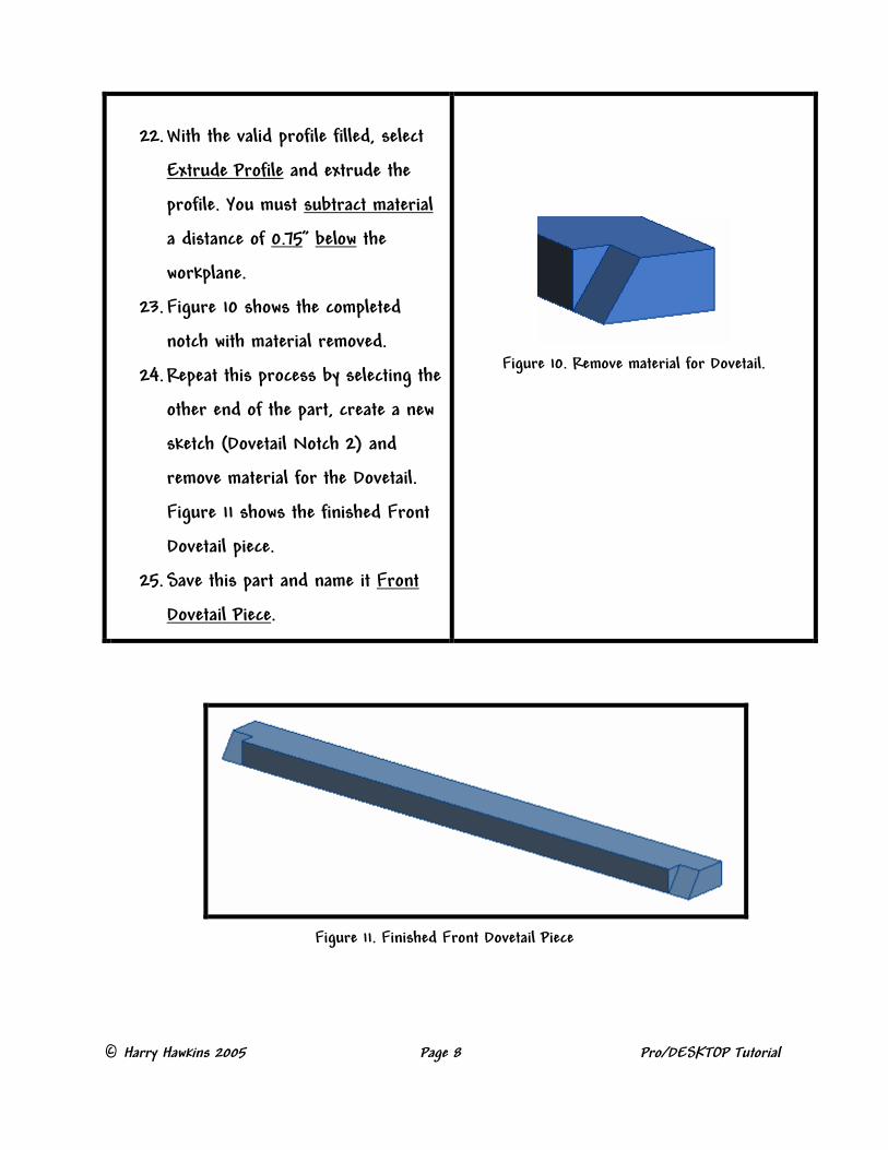
17. Open a new design (Ctrl + N)
18. Draw a valid profile according to
the dimensions given on page 2 and
figure 8.
19. Once you have a valid (filled)
profile, select Extrude Profile and
extrude the profile 0.75” above the
workplane.
Figure 8. Dimensions for Front Dovetail Piece.
20. Use face selection to select one end
face of the extrusion. It will turn
red. Right Click and select New
Sketch. Name it Dovetail Notch 1.
21. Draw the valid notch triangle for
the notch as shown in figure 9.
Figure 9. Dovetail notch triangle profile.
© Harry Hawkins 2005 Page 8 Pro/DESKTOP Tutorial
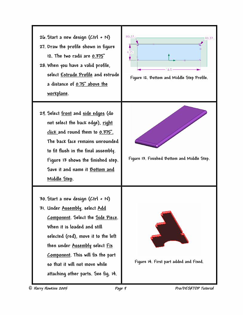
Figure 11. Finished Front Dovetail Piece
22. With the valid profile filled, select
Extrude Profile and extrude the
profile. You must subtract material
a distance of 0.75” below the
workplane.
23. Figure 10 shows the completed
notch with material removed.
24. Repeat this process by selecting the
other end of the part, create a new
sketch (Dovetail Notch 2) and
remove material for the Dovetail.
Figure 11 shows the finished Front
Dovetail piece.
25. Save this part and name it Front
Dovetail Piece.
Figure 10. Remove material for Dovetail.
© Harry Hawkins 2005 Page 9 Pro/DESKTOP Tutorial
26. Start a new design (Ctrl + N)
27. Draw the profile shown in figure
12. The two radii are 0.375”
28. When you have a valid profile,
select Extrude Profile and extrude
a distance of 0.75” above the
workplane.
Figure 12. Bottom and Middle Step Profile.
29. Select front and side edges (do
not select the back edge), right
click and round them to 0.375”.
The back face remains unrounded
to fit flush in the final assembly.
Figure 13 shows the finished step.
Save it and name it Bottom and
Middle Step.
Figure 13. Finished Bottom and Middle Step.
30. Start a new design (Ctrl + N)
31. Under Assembly, select Add
Component. Select the Side Piece.
When it is loaded and still
selected (red), move it to the left
then under Assembly select Fix
Component. This will fix the part
so that it will not move while
attaching other parts. See fig. 14.
Figure 14. First part added and Fixed.
© Harry Hawkins 2005 Page 10 Pro/DESKTOP Tutorial
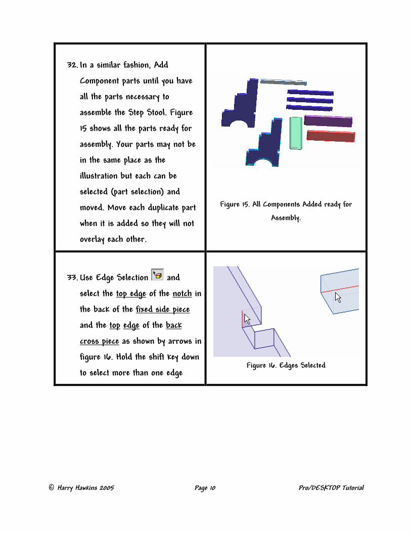
32. In a similar fashion, Add
Component parts until you have
all the parts necessary to
assemble the Step Stool. Figure
15 shows all the parts ready for
assembly. Your parts may not be
in the same place as the
illustration but each can be
selected (part selection) and
moved. Move each duplicate part
when it is added so they will not
overlay each other.
Figure 15. All Components Added ready for
Assembly.
33. Use Edge Selection and
select the top edge of the notch in
the back of the fixed side piece
and the top edge of the back
cross piece as shown by arrows in
figure 16. Hold the shift key down
to select more than one edge
Figure 16. Edges Selected

© Harry Hawkins 2005 Page 11 Pro/DESKTOP Tutorial
34. With the two edges selected (red),
right click and select Center Axis.
The cross piece will center with
the notch. Use part selection to
select the cross piece and move it
so it is similar to figure 17. It will
slide in the constraint plane. Be
sure to move the cross piece so
that the left end is near the
notch.
Figure 17. Cross Piece moved prior to mating.
35. The Center constraint applied to
the cross piece may need to be
suppressed so that another
constraint can be applied. To do
this, select Components in the
browser, then highlight Back
Cross Piece. See figure 18. Notice
at the bottom of the browser a
Constraint tree will be visible.
Right click on any constraint and
select Suppress. Now Right Click
on any remaining constraints and
select Suppress. This will
suppress all constraints and allow
you to apply another constraint.
Figure 18. Suppressing Constraints.
© Harry Hawkins 2005 Page 12 Pro/DESKTOP Tutorial
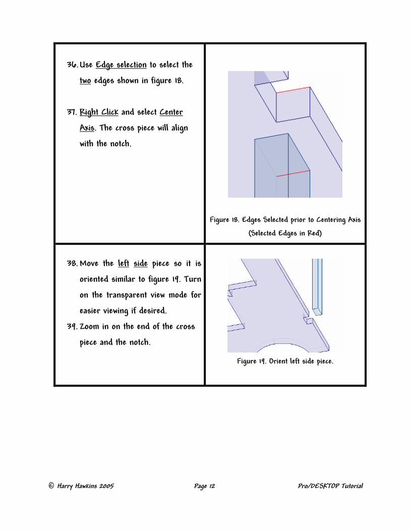
36. Use Edge selection to select the
two edges shown in figure 18.
37. Right Click and select Center
Axis. The cross piece will align
with the notch.
Figure 18. Edges Selected prior to Centering Axis
(Selected Edges in Red)
38. Move the left side piece so it is
oriented similar to figure 19. Turn
on the transparent view mode for
easier viewing if desired.
39. Zoom in on the end of the cross
piece and the notch.
Figure 19. Orient left side piece.
© Harry Hawkins 2005 Page 13 Pro/DESKTOP Tutorial
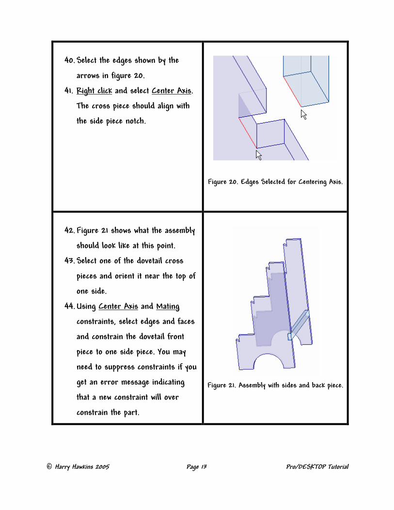
40. Select the edges shown by the
arrows in figure 20.
41. Right click and select Center Axis.
The cross piece should align with
the side piece notch.
Figure 20. Edges Selected for Centering Axis.
42. Figure 21 shows what the assembly
should look like at this point.
43. Select one of the dovetail cross
pieces and orient it near the top of
one side.
44. Using Center Axis and Mating
constraints, select edges and faces
and constrain the dovetail front
piece to one side piece. You may
need to suppress constraints if you
get an error message indicating
that a new constraint will over
constrain the part.
Figure 21. Assembly with sides and back piece.
© Harry Hawkins 2005 Page 14 Pro/DESKTOP Tutorial
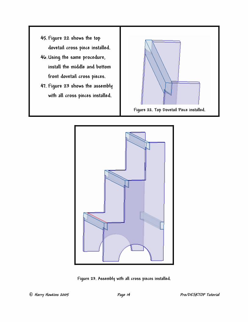
45. Figure 22 shows the top
dovetail cross piece installed.
46. Using the same procedure,
install the middle and bottom
front dovetail cross pieces.
47. Figure 23 shows the assembly
with all cross pieces installed.
Figure 22. Top Dovetail Piece installed.
Figure 23. Assembly with all cross pieces installed.

© Harry Hawkins 2005 Page 15 Pro/DESKTOP Tutorial
48. Select the top step and orient it
near the top of the sides. Use
edge select, select one of the
outside edges of the top and a
corresponding outside edge of the
step end. Do not select the
outside of the round. Use Center
Axis to constrain the step to both
directions so the step fits exactly
on top of the sides. Figure 24
shows the step installed.
Figure 24. Top step installed.
49. In a similar fashion, install the
middle and bottom steps. Use
edge and face selection and
constraints such as Center Axis
and Mating. You may need to
suppress some constraints in
order to apply new constraints.
50. Figure 25 show the completed
step stool. Save it and name it
Step Stool Assembly.
Figure 25. Completed Assembly
© Harry Hawkins 2005 Page 16 Pro/DESKTOP Tutorial
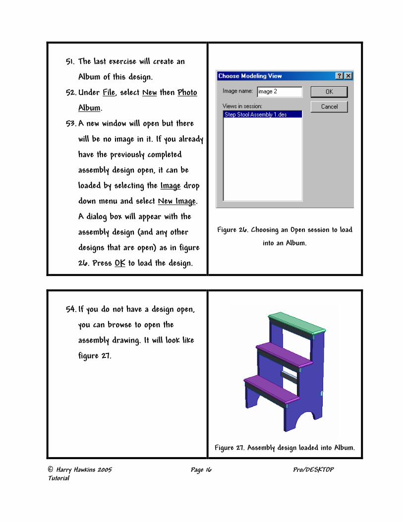
51. The last exercise will create an
Album of this design.
52. Under File, select New then Photo
Album.
53. A new window will open but there
will be no image in it. If you already
have the previously completed
assembly design open, it can be
loaded by selecting the Image drop
down menu and select New Image.
A dialog box will appear with the
assembly design (and any other
designs that are open) as in figure
26. Press OK to load the design.
Figure 26. Choosing an Open session to load
into an Album.
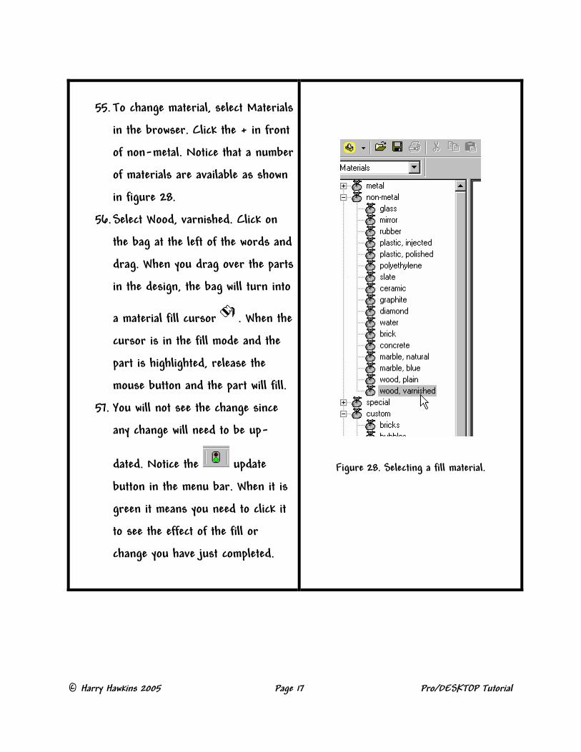
54. If you do not have a design open,
you can browse to open the
assembly drawing. It will look like
figure 27.
Figure 27. Assembly design loaded into Album.
© Harry Hawkins 2005 Page 17 Pro/DESKTOP Tutorial
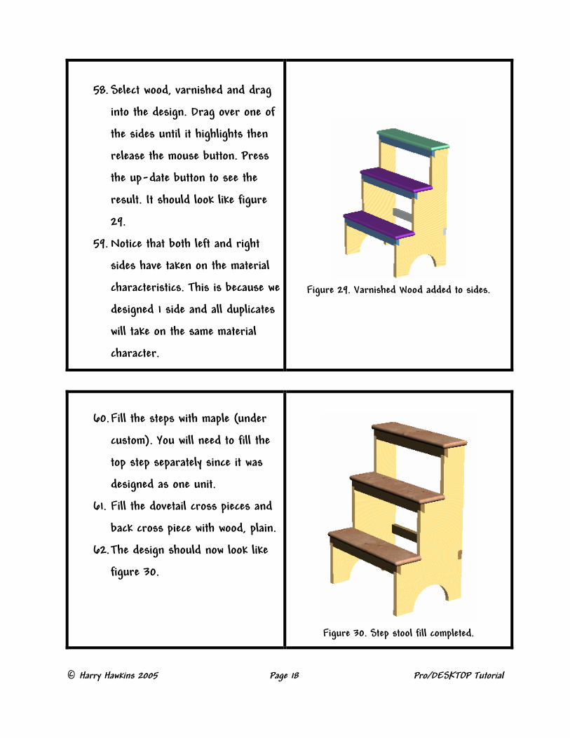
55. To change material, select Materials
in the browser. Click the + in front
of non-metal. Notice that a number
of materials are available as shown
in figure 28.
56. Select Wood, varnished. Click on
the bag at the left of the words and
drag. When you drag over the parts
in the design, the bag will turn into
a material fill cursor . When the
cursor is in the fill mode and the
part is highlighted, release the
mouse button and the part will fill.
57. You will not see the change since
any change will need to be up-
dated. Notice the update
button in the menu bar. When it is
green it means you need to click it
to see the effect of the fill or
change you have just completed.
Figure 28. Selecting a fill material.
© Harry Hawkins 2005 Page 18 Pro/DESKTOP Tutorial
58. Select wood, varnished and drag
into the design. Drag over one of
the sides until it highlights then
release the mouse button. Press
the up-date button to see the
result. It should look like figure
29.
59. Notice that both left and right
sides have taken on the material
characteristics. This is because we
designed 1 side and all duplicates
will take on the same material
character.
Figure 29. Varnished Wood added to sides.
60. Fill the steps with maple (under
custom). You will need to fill the
top step separately since it was
designed as one unit.
61. Fill the dovetail cross pieces and
back cross piece with wood, plain.
62. The design should now look like
figure 30.
Figure 30. Step stool fill completed.
© Harry Hawkins 2005 Page 19 Pro/DESKTOP Tutorial
63. You can change the color of any
part by highlighting it then right
click. A color selection box can be
used to select any desired color.
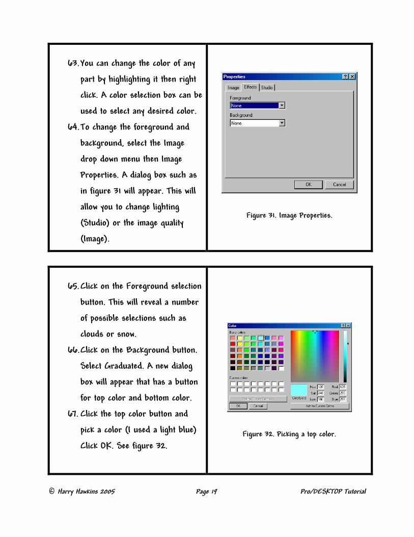
64. To change the foreground and
background, select the Image
drop down menu then Image
Properties. A dialog box such as
in figure 31 will appear. This will
allow you to change lighting
(Studio) or the image quality
(Image).
Figure 31. Image Properties.
65. Click on the Foreground selection
button. This will reveal a number
of possible selections such as
clouds or snow.
66. Click on the Background button.
Select Graduated. A new dialog
box will appear that has a button
for top color and bottom color.
67. Click the top color button and
pick a color (I used a light blue)
Click OK. See figure 32.
Figure 32. Picking a top color.

© Harry Hawkins 2005 Page 20 Pro/DESKTOP Tutorial
68. Click the bottom color button and
select a color (dark blue) Click OK
then click OK to get back to the
design.
69. Click the up-date button and notice
that the background now starts at a
light blue at the top and gradually
changes to dark blue at the bottom
as shown in figure 33.
70. Save this album and give any name
you choose.
Figure 33. Graduated background.
71. You can also change the quality of
the image by increasing the pixel
setting.
72. Under Image properties, select
Image. The dialog box in figure 34
will appear. Notice you can set the
rendering quality to Presentation
and change the pixel resolution to a
number of high values. Figure 35 is
the image after setting the values
shown in figure 34.
Figure 34. Setting the quality of the image.
© Harry Hawkins 2005 Page 21 Pro/DESKTOP Tutorial
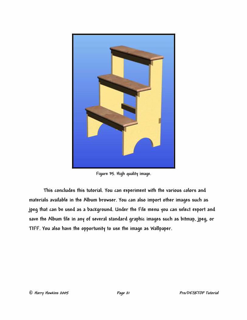
Figure 35. High quality image.
This concludes this tutorial. You can experiment with the various colors and
materials available in the Album browser. You can also import other images such as
jpeg that can be used as a background. Under the File menu you can select export and
save the Album file in any of several standard graphic images such as bitmap, jpeg, or
TIFF. You also have the opportunity to use the image as Wallpaper.


