
Mitsubishi Electric power devices meet demands for energy-saving and eco-friendly semiconductors with advanced technology and a diversified product line-up. Industrial use, traction, home appliances ... wherever electric power or motor control is needed, we have the means and tools to respond, including the industry's first DIPIPMsTM (Dual-In-line Package Intelligent Power Modules), and the HVIPMs (High-voltage Intelligent Power Modules).
State-of-the-art technology pursuing energy-savingsand environmental protection.
Power Devices General Catalog
Applications
Trends in Power Device Technology
Power Modules
High-power Devices
High-voltage Integrated Circuits
Transistor Arrays
1
3
5
37
53
54

100M
10M
1M
100k
10k
10k
1k
1k
100
100
10
Cap
acity
(V
A)
Industrial
HomeAppliances
Operation Frequency (Hz)
Thyristor
GCT/GTO thyristor
Triac
IGBT
IPM
IGBTmodule
� Electric power� UPSs
� Welders� Iron mills
� Inductionheating cookers
� Medicalequipment
� Robots� Welders
� Motor control
� Wind power
� Solar power� Inverters
� Automotive
� Air conditioners� Refrigerators� Washing machines
� Electric ovens� Electric fans� Washing
machines
HVIGBTHVDiHVIPM
� Electric power� Iron mills� Electric trains
DIPIPM TM
Thyristor
GCT/GTO thyristor
IPM
IGBTmodule
HVIGBTHVDiHVIPM
DIPIPM TM
1M
100k
MOSFET
Forecast
Now
1
Power Devices Offering UnlimitedApplications
Mitsubishi Electric powerdevices have a wide varietyof applications in variousfields, such as industrialmachinery, electric railways,office automation, householdpower appliances and motorcontrol. We are pursuing improve-ments in energy efficiency,development of technologiesthat reduce power consump-tion, and the expansion ofour product line-up.
2
Air conditioners
Refrigerators
Washing machines
Ind
ust
rial
use
Hom
e A
pplia
nces
IGBTmoduleIPMDIPIPMTM
GCT/GTO
thyristorThyristor HVIGBT
HVIPM
Electric power
Electric Trains
Iron mills
Automotive
UPSs
Motor control
Welders
Inverters
Medical equipment
Wind powerSolar power
�1
�1
� Main application & products
�1: This is limited to the case when the relevant mutual parties can confirm and agreewith the operating conditions, quality control and guarantee system
Application Potential

3 4
CSTBTTM has achieved an extremely low-loss structure by advancing a conventional trench structure IGBT.In addition to the conventional trench structure, CSTBTTM has a carrier-stored n layer to accumulate carriers as shown in the diagram on the right. The concentration of the n layer (conservation of charge layer) connected with the p base layer is higher than the n– layer, and the internal electric potential difference between the p base and the n layer is higher than that of the p base and the n– layer.This high internal electric potential serves as a barrier to prevent holes infused from the p+ layer to n– layer from going through to the emitter side. In short, holes can be stored on the emitter side of an element by the conservation of a charge layer, and the n layer controls the shift of holes to the p base layer.This conservation of charge function drastically improves the on-state characteristics of CSTBTTM, compared to the trench structure of IGBTs. Increasing the carrier density on the emitter side and decreasing the impedance in silicon makes on-state voltage reduction possible.
CSTBTTM: Mitsubishi Electric's original IGBT, utilizing a novel carrier storage effect
High-hFEBip. Tr. (module)
Bip. Tr. (module)
IGBT(module)
Bipolar power transistor (Bip. Tr.)
Power MOSFET
Power MOSFET module
TrenchIGBT
Reverse-conductingthyristor
Light-triggeredthyristor
Thyristor
GTO
GCT
GTO
GCT
IPMIPM
HEV-IPM
CSTBTTM
600V
1200V
ASIPM
DIPIPMTM
HVIPM
1950 1970 1980 2000 20101990
ASIPM
DIPIPMTM
HVIPM
HEV-IPM
CSTBTTM
600V
1200V
� Advances in power devices
High-hFEBip. Tr. (module)
Bip. Tr. (module)
IGBT(module)
New-type MOS gate device
Bipolar power transistor (Bip. Tr.)
Trends in Power DeviceTechnology
The technological progress of power devices is closely related to market needs. There is a constant requirement for them to be less noisy, more efficient, smaller, lighter, more advanced in function, more accurate, and have larger capacities.In order to meet these needs with precision, Mitsubishi Electric is now accelerating the improvement of its existing devices and the research and development of new devices. Energetic efforts are being mode to develop and commercialize IGBT modules, and in particular IPMs.
Actual Principle of CSTBTTM
Utilizing reduced surface field (RESURF) technology, Mitsubishi Electric Corporation has developed a 1200V horizontal MOSFET for level shift circuits.We have further developed a split-RESURF structure for level shift technology without high-potential wiring.Our high-voltage integrated circuits (HVICs) have a high-rating of 1200V.
Reverse-conductingthyristor
Light-triggeredthyristor
Thyristor
High-voltage IC
Power MOSFET
Power MOSFET module
TrenchIGBT
High-voltage Technology of1200V HVICs
The split-RESURF structure is characterized by a narrow p– substrate area exposed on the surface between the drain and island areas of the horizontal MOSFET for level shift circuits.When high-voltage is applied across the power supply electrodes, the p– substrate becomes a depletion layer between the n-diffusion areas; therefore, the surface potential of this p– substrate area is not significantly different from that of the n-diffusion areas.In the past, HVIC maximum ratings were limited to 600V because, under high-potential wiring, a dielectric film is required to have the ability to withstand the same voltage as semiconductor junctions. The split-RESURF structure enables an HVIC to achieve a rating of 1200V.
Emitter electrode
p base layer
n– layer
n+ buffer layer
p+ sub layer
Collector electrode
Barrier metal layer
Gate oxide layer
p+ layer
Emitter layerPolysilicon gate
Carrier stored n layer
n– layer
n+ bufferlayer
p+ substrate
n+ emitter n+ emitter
Collector electrode
n– layer
n+ bufferlayer
p+ substrate
Collector electrode
Trench IGBT CSTBTTM
p+ hole
Potentialbarrier forp+ hole
n+electron
n+electron
p+ hole
Carrierstoredn layer
� CSTBTTM chip structure � Comparison of trench IGBT and CSTBTTM
Hole density VCE(sat) vs, Eoff
Cathode side
Increase
Anode side
IGBTCSTBTTM
Low High
Eoff
VCE(sat)
TrenchIGBT
CSTBTTM
When the n– layer is thick enough When RESURF technology is applied
The p– substrate depletion layer forcibly extends the p+n– junction depletion layer underneath the surface. The n– layer becomes a complete depletion layer, and the surface electric field is thereby reduced.The RESURF structure has the ability to withstand high-voltage in the vertical direction because the p– substrate depletion layer extends in the depth direction. The rating of the entire device can therefore be increased significantly.
n–p+
p–
n+n– well
n– well n well n well
p+
p
n+ n+
p
p– substrate
� What is RESURF?
High-voltage island area
� What is split-RESURF structure?
E
E
Source Gate Drain
Depletion layer Depletion layer

5
Power Modules
�: Please refer to high-power device for IGBTmodules over 2500V
PM25 to 800A 600 to 1200V
TM20 to 400A 300 to 1600V
FM100 to 300A 75 to 150V
MOSFET Module
PS3 to 75A 600V/1200V
DIPIPM TM
Intelligent Power Module
RM20 to 500A 300 to 2000V
Diode Module
Thyristor Module
PowerModule
ClassificationCM
50 to 1400A 250 to 1700V
IGBT Module
�
Change of appearance or othersRated currentChange of IGBT chipChange of packageVoltage classSeries name
PS
Series nameVoltage classChange of appearance or othersSeries nameConnectionRated currentType
CM 150 D Y -24 NFPM 100 R L A 120
PS
� Codes for power module naming
� Codes for DIPIPM TM naming
� Application of IPM/IGBT to AC motor controls(VVVF inverter, servo amps, etc.)
Converter Brake Inverter
IM
The power module is a compound-type semiconductor that is installed in apackage after wiring semiconductor chips to meet the application needs andspecifications. Power modules are classified into diodes, thyristors, IGBTsand intelligent power modules (IPMs) according to the type of chips installed.Since 1978, when we placed these power modules in practical use,Mitsubishi Electric has always been endeavoring to extend the correspondingmarket through developing new devices. In recent years, the demand forIGBT modules and IPMs has rapidly increased and we are doing our utmostto develop products and improve product characteristics in this field.
� Features:� New package design for less environmental pollution, which also contributes
to energy savings due to reduced power loss� Long creeping distance and high dielectric strength (1500V to 3500V)� Since we offer a variety of models in terms of voltage, current, wiring pattern,
etc., our power modules can be used in a wide range of applications such asinverters, choppers and uninterruptible power supplies (UPSs)
� Compliance with international standards (UL1557) has been certified (YellowCard No. E80276, File No.E80271) (excluding some products)
� The ease of both installation and wiring due to the design allows applicationequipment to be reduced in size and weight
Industry-leading Technologies and a Wide Range of Products

6
DIPIPMTM
Dual In-line Package Intelligent Power Module
DIPIPMTM Series are being used widely in both home appliances such as air conditioners, refrigerators and washing machines,as well as small-capacity industrial equipment such as inverters and servo amplifiers.They contribute greatly to power-savings and product miniaturization.In addition to 600V-rated devices, 1200V-rated devices designed for the global market are included in the line-up.
� Applications� Air conditioners, refrigerators, washing machines, and package air conditioners� Low-power industrial motor drives
� Features� Wide line-up from 3A to 75A/600V, and 5A to 35A/1200V� Use of low-loss IGBT or CSTBTTM
� Direct drive by control unit possible (non-optocoupler interface)� Single supply scheme simplifies the power supply circuits� External-terminal plating using a lead-free solder in compliance with the
RoHS directiveThe lead-free solder is used for soldering the power chips in the DIPIPMTM
Ver. 4 series
Strongly supporting smaller and more energy-savingelectric home appliances and low-power industrial equipment.
� Series map
Mini DIPIPMTM Ver. 3 Series� PS2156✱-P� PS2156✱-SP
Large DIPIPMTM Ver. 3 /3.5 Series� PS2126✱-P/-AP� PS21869-P/-AP
Large DIPIPMTM
Ver. 4 Series� PS21A7✱
DIPPSCTM Series� PS81B9✱-A/-W
DIPPFCTM Series 1)
� PS5178✱
Mini DIPIPMTM
Ver. 4 Series� PS2176✱
Large DIPIPMTM Ver. 4 Series� PS22A7✱
Super-mini DIPIPMTM Ver. 4 Series� PS2196✱-4/-4S/-T/-ST� PS2199✱-4/-T
VCES
(V)
600V
1200V
Ic (A)3A 5A 10A 15A 20A 25A 30A 35A 50A 75A
1) PS5178✱ correspond to input current 20Arms and 30Arms
7
� Line-up
� Block diagram
AC line inputAC output
Inrush limiter
Z C
Input signal conditioning
N-side input (PWM)
Fo logic
Drive circuit
N-side IGBTs
P-side IGBTs
Protectioncircuit
Control supplyUV protection
VNC CIN
N1 N
P
P-side input (PWM)
MU
V
W
(15V line)VNC VD
Fault outputFo
DIPIPMTM
Input signalconditioning
Level shifter
Protectioncircuit (UV)
Drive circuit
Input signalconditioning
Level shifter
Protectioncircuit (UV)
Drive circuit
Input signalconditioning
Level shifter
Protectioncircuit (UV)
Drive circuit
PS219✱✱
Bootstrap circuit
Super-mini and Mini DIPIPMTM Ver. 4 SeriesSuper-mini and Mini Dual In-line Package Intelligent Power Module Ver. 4 Series
� Applications� Low-power home appliances
(air conditioners, washing machines and refrigerators)� Small-capacity industrial motor drives
� Internal functions� For P-side IGBTs:
Drive circuit, high-voltage, high-speed level shifting, andcontrol supply under-voltage (UV) protection
� For N-side IGBTs:Drive circuit, control supply under-voltage (UV)protection, and short-circuit (SC) protectionOver-temperature (OT) protection [ -T series only ]
� Error output:Corresponds to SC, UV (N-side only), and OT protection
� IGBT drive power supply:15VDC single power supply (bootstrap supply schemecan be applied)
� Input interface:3V, 5V compatible, high active logic
� Features� Use of an insulated thermal radiating sheet structure
realizes low thermal resistance� A lead-free solder is used in terminal plating and power
chip soldering (RoHS directive compliance)
-V: Higher switching speed
PS2196✱Series
Isolation voltage1500Vrms class
Type RatingsOutline
drawingsno.
fcmax.(kHz)
PS21963-4E/-4ES/-ET/-ESTPS21962-4/-4S/-T/-ST
PS21964-4/-4S/-T/-ST20
8A/600VPS21963-4/-4S/-T/-ST 10A/600V
5A/600V
Isolation voltage2500Vrms class
Mini-package Series
Super-mini-package Series
Type RatingsOutline
drawingsno.
fcmax.(kHz)
PS21767/-V20
30A/600VPS10
PS21765 20A/600V
PS21961-4/-4S/-T/-ST 3A/600V
15A/600VPS21965-4/-4S/-T/-ST 20A/600VPS21997-4/-T 30A/600V
PS1PS2PS3
(�2)
PS4
�1: Corresponds to isolation voltage 2500Vrms in the case of using the convex-shaped heat sink�2: 3 shunts type is not available for PS21997-T: Over temperature protection is available-S: N-side open emitter (3 shunts)(Other 3 terminal forming types are available)
(�1)
(PS219✱✱ block diagram)

8
DIPIPMTM Ver. 3/3.5 SeriesDual In-line Package Intelligent Power Module Ver. 3/3.5 Series
� Line-up
� Block diagram
AC line inputAC output
Inrush limiter
Input signal conditioning
N-side input (PWM)
Fo logic
Drive circuit
N-side IGBTs
P-side IGBTs
Protectioncircuit
Control supplyUV protection
VNC CIN
N1 N
P
P-side input (PWM)
MU
V
W
Bootstrap circuit
(15V line)VNC VDFault output
Fo CFo
DIPIPMTM
Input signalconditioning
Level shifter
Protectioncircuit (UV)
Drive circuit
Input signalconditioning
Level shifter
Protectioncircuit (UV)
Drive circuit
Input signalconditioning
Level shifter
Protectioncircuit (UV)
Drive circuit
PS2186✱
Z C
� Applications� Low-power home appliances
(air conditioners, washing machines, refrigerators)� Small-capacity industrial motor drives
� Internal functions� For P-side IGBTs:
Drive circuit, high-voltage, high-speed level shifting, andcontrol supply under-voltage (UV) protection
� For N-side IGBTs:Drive circuit, control supply under-voltage (UV)protection, and short-circuit (SC) protection
� Error output:Corresponds to SC and UV (N-side only) protection
� IGBT drive power supply:15VDC single power supply (bootstrap supply schemecan be applied)
� Input interface:3V, 5V compatible, high active logic
� Features� A lead-free solder is used in terminal plating
(RoHS directive compliance)
-SP: N-side open emitter (3 shunts)
-AP: Long outer terminal
Isolation voltage2500Vrms class
TypeVer. RatingsOutline
drawingsno.
fcmax.(kHz)
PS21563-P/-SP20
10A/600VPS21564-P/-SP 15A/600VPS21565-P/-SP 20A/600V
PS5PS6
PS21562-P/-SP 5A/600V
3
Mini-package Series
Isolation voltage2500Vrms class
TypeVer. RatingsOutline
drawingsno.
fcmax.(kHz)
PS21265-P/-AP 20A/600VPS21267-P/-AP 30A/600VPS21869-P/-AP 50A/600V
20 PS9
20 PS7
3.5
3
Large-package Series
(PS2186✱ block diagram)
9
Large DIPIPMTM Ver. 4 SeriesLarge Dual In-line Package Intelligent Power Module Ver. 4 Series
� Line-up
� Applications� Low-power appliances
(air conditioners, general-purpose inverter, AC servoamplifier, etc.)
� Internal functions� For P-side IGBTs:
Drive circuit, high-voltage, high-speed level shifting, andcontrol supply under-voltage (UV) protection
� For N-side IGBTs:Drive circuit, control supply under-voltage (UV)protection, and short-circuit (SC) protection
� Error output:Corresponds to SC and UV (N-side only) protection
� IGBT drive power supply:15VDC single power supply (bootstrap supply schemecan be applied)
� Input interface:5V compatible, high active logic
� Block diagram
AC line input AC output
Input signal conditioning
Temp. Output
N-side input (PWM)
Fo logic
Drive circuit
N-side IGBTs
P-side IGBTs
Protectioncircuit
Control supplyUnder-Voltageprotection (UV)
VNC VSC
CIN
N
P
P-side input (PWM)
MU
V
W
Bootstrap circuit
VNC VD
Fooutput
CFo
Input signalconditioning
Level shifter
Protectioncircuit (UV)
Drive circuit
Input signalconditioning
Level shifter
Protectioncircuit (UV)
Drive circuit
Input signalconditioning
Level shifter
Protectioncircuit (UV)
Drive circuit
PS21A7✱
VOT
Z C
DIPIPMTM
Inrush limiter
Isolation voltage2500Vrms class
Type RatingsOutline
drawingsno.
fcmax.(kHz)
PS21A7A
20
75A/600VPS22A72 5A/1200VPS22A73 10A/1200VPS22A74 15A/1200VPS22A76 25A/1200VPS22A78-E 35A/1200V
PS8
20 PS8PS21A79 50A/600V
Large-package Series
� Features� Outputting LVIC temperature by analog signal� Use of an insulated thermal radiating sheet structure
realizes low thermal resistance� A lead-free solder is used in terminal plating and power
chip soldering (RoHS directive compliance)
(PS21A7✱ block diagram)

10
Mini DIPPFCTM SeriesMini Dual In-line Package Power Factor Correction Series
Isolationvoltage2500Vrmsclass
TypeRatings
Input voltage Input current
Outlinedrawings
no.fc
typ.(kHz)
20 PS10PS51789
PS5178790 to 264Vrms
30Arms
20Arms
Mini DIPPFCTM Series
� Block diagram
AC line input
Reactor
AC output
MU
V
W
PS5178✱
Control supplyUnder-Voltageprotection (UV)
Control ICM63914
MCU
Drivecircuit
Inverter circuit
Input signalconditioning
R
P
S
N2
GNDN
VD (15V line)
GND
VIN
DIPPFCTM
� Applications� Air conditioners, general purpose inverters, etc.
� Internal functions� Low-loss IGBT� Rectifier circuit� IGBT drive circuit� Control supply under-voltage protection (UV)
� Features� A lead-free solder is used in terminal plating
(RoHS directive compliance)� Special IC M63914FP for DIPPFCTM control is available.
The combination with the IC can offer short circuit and overvoltage protection
� Line-up
(PS5178✱ block diagram)

11
DIPPSCTM SeriesDual In-line Package Partial Switching Circuit Series
Isolationvoltage2500Vrmsclass
TypeRatings
Partial SW part Inverter part Inverter part
Outlinedrawings
no.
fcmax.(kHz)
PS81B94-A/-W20
15A/600V
PS81B95-A/-W20A/600V20A/600V
PS11PS12
PS81B93-A/-WPS81B93-AE/-EW 15A/600V
10A/600V15A/600V20A/600V
8A/600V
-A : Long outer terminal-W: Both sides zigzag terminal
DIPPSCTM Series
� Block diagram
AC line output
Input signal conditioning
Temp. Output
N-side input (PWM)
Fo logic
Drive circuit
N-side IGBTs
P-side IGBTs
Protectioncircuit
Control supplyUnder-Voltageprotection (UV)
CIN
NUNVNW
P
S
R
P-side input (PWM)Fault output
AFoPSC part input
MU
V
W
VNC VD (17V line)
Fo CFo
DIPPSCTM
Input signalconditioning
Level shifter
Protectioncircuit (UV)
Drive circuit
Input signalconditioning
Protectioncircuit(UV)
Level shifter
Protectioncircuit (UV)
Drive circuit
Input signalconditioning
Level shifter
Protectioncircuit (UV)
Drive circuit
Input signalconditioning
Protectioncircuit
Fologic
Drive circuit
PS81B9✱
VOT
Z C
VNC
VAC
VAC VA1(15V line)
VNO
VRS
Fault output
PSC part Inverter part
AC line input
Reactor
� Applications� Low-power home appliances
(air conditioners, washing machines and refrigerators)� Small-capacity industrial motor drive
� Internal functions� Inverter part
� For P-side IGBTs:Drive circuit, high-voltage, high-speed level shifting,and control supply under-voltage (UV) protection
� For N-side IGBTs:Drive circuit, control supply under-voltage (UV)protection, .and short-circuit (SC) protection
� Error output:Corresponds to SC and UV (N-side only) protection
� IGBT drive power supply:17VDC single power supply (bootstrap supply schemecan be applied)
� Input interface: 3, 5V compatible, high active logic
� PSC partDrive circuit, control supply under-voltage (UV) protection,and Short-circuit (SC) protectionError output for SC and UV protection
� Line-up
� Features� Built-in PSC (Partial Switching Circuit) for power factor corrector� Outputting LVIC temperature by analog signal� Use of an insulated thermal radiating sheet structure
realizes low thermal resistance.� A lead-free solder is used in terminal plating
(RoHS directive compliance)
(PS81B9✱ block diagram)

12
IPM Intelligent Power Modules
In recent years, new demands for ease-of-use andenvironmental concerns have been added to the need forimproved performance, miniaturization, compactness andreduced power loss in motor controllers such as generalpurpose inverters and AC servos for industrial equipment.Mitsubishi Electric is already in production of power modules
such as the 3rd-generation IPM "S Series" and 4th-generation IPM "S-DASH Series", and now adds theminiaturized and lightweight 5th-generation "L Series" to itsline-up. The "L Series" incorporates a CSTBTTM chip forreduced power loss and a new compact package.
� Intelligent Power Modules (L1 Series)
� IPM series map
600V
1200V
VCES
(V) Connection Mainterminal
Connection Mainterminal
ScrewPin
Screw
3�
3�+Brake Pin
600
50 75 100 150 200 300
PM100CL1A060PM75CL1A060 PM150CL1A060 PM200CL1A060 PM300CL1A060
PM50RL1A060PM50CL1B060PM50CL1A060
PM75RL1A060 PM100RL1A060 PM150RL1A060PM100CL1B060PM75CL1B060 PM150CL1B060 — —
PM200RL1A060
—
PM300RL1A060
—PM50RL1B060PM50RL1C060 PM75RL1B060 PM100RL1B060 PM150RL1B060
Ic (A)
VCES
(V)
3rd-generation (former) 3rd-generation (latter) 4th-generation 5th-generation
ScrewPin
Pin
Screw
3�
3�+Brake
1200
25 50 75 100 150
PM75CL1A120PM50CL1A120 PM100CL1A120 PM150CL1A120
PM25RL1A120PM25CL1B120PM25CL1A120
PM50RL1A120 PM75RL1A120 PM100RL1A120PM75CL1B120PM50CL1B120 — —
PM150RL1A120
—PM25RL1B120PM25RL1C120 PM50RL1B120 PM75RL1B120 —
Ic (A)
S-DASH SeriesV SeriesS Series
L Series
L1 Series
S1 SeriesS-DASH Servo Series
V Series, S-DASH Series, S-DASH Servo Series, L Series, L1 Series, S1 Series are RoHS directive compliance.S Series are not RoHS directive compliance.
� Applications� Motor control devices
(220VAC/440VAC inverters, servos, etc.)� DC power supplies such as UPS� IPMs for photovoltaic generation using solar devices series
� Features (L1/S1 Series) � Low-loss by new CSTBT TM chip optimized VCE(sat) vs
Eoff trade-off� Optimized thermal sensor on chip (Tj sensor)� Improved of power cycle capability� Completely lead-free (RoHS directive compliance)� The package compatible to the L-Series IPM .....L1 Series� Adoption of new small-package
(50A/600V and 25A/1200V Pin type) ............L1 Series

13
L S
erie
s P37
P38
OC: Overcurrent protectionSC: Short-circuit protectionUV: Control supply under-voltageOT: Over-temperature protection
BR : Elements for braking controlPFo: P-side fault outputNFo: N-side fault output
: Built-in integrated: Non-integrated
�
�
PM200CLA060PM300CLA060PM450CLA060PM600CLA060
200300450600
�
�
�
�
�
�
�
�
�
�
�
�
�
�
�
�
�
�
�
�
�
�
�
�
�
�
�
�
2230
37/4555
L1
Ser
ies
S1
Ser
ies
P35P36P35P36P35P36P35P36
P37
P35P36P35P36P35P36P35P36
P37
P39
VacPhaseIC(A)VCES(V)Applicable motor
rating(kW)Outline
drawingsno.
TypeOutput characteristicsRating Built-in functions
OC SC UV OT BR PFo NFo
220VAC for Line
PM50RL1A060PM50RL1B060PM75RL1A060PM75RL1B060PM100RL1A060PM100RL1B060PM150RL1A060PM150RL1B060PM200RL1A060PM300RL1A060PM50CL1A060PM50CL1B060PM75CL1A060PM75CL1B060PM100CL1A060PM100CL1B060PM150CL1A060PM150CL1B060PM200CL1A060PM300CL1A060PM50RL1C060
50
75
100
150
200300
50
75
100
150
20030050
3.7� �
�
�
�
�
�
�
�
�
�
�
�
�
�
�
�
�
�
�
�
�
�
�
�
�
�
�
�
�
�
�
�
�
�
�
�
�
�
�
�
�
�
�
�
�
�
�
�
�
�
�
�
�
�
�
�
�
�
�
�
�
�
�
�
�
�
�
�
�
�
�
�
�
�
�
�
�
�
�
�
�
�
�
�
�
�
�
�
�
�
�
�
�
�
�
�
�
�
�
�
�
�
�
��
�
�
�
�
�
�
�
�
�
�
�
�
�
�
�
�
�
�
�
�
�
�
�
�
�
�
�
�
�
�
�
�
�
�
�
�
�
�
�
�
�
P40
� � � �� ��� � � �� ��� � � �� ��� � � �� ��� � � �� ��
5.5/7.5
11
15/18.5
2230
3.7
5.5/7.5
11
15/18.5
22303.7
PM50CS1D060 50 3.7PM75CS1D060 75 5.5/7.5PM100CS1D060 100 11PM150CS1D060 150 15/18.5PM200CS1D060 200 22
600 2203
� High-speed intelligent power modules
IPMIntelligent Power Modules

14
IPMIntelligent Power Modules
P26
P27
P25
P28P29
OC: Overcurrent protectionSC: Short-circuit protectionUV: Control supply under-voltageOT: Over-temperature protection
BR : Elements for braking controlPFo: P-side fault outputNFo: N-side fault output
: Built-in integrated: Installed only with N-side: Non-integrated
�
��
PM100CVA060PM150CVA060PM200CVA060PM300CVA060
PM75RVA060
PM400DVA060PM600DVA060
100150200300
75
400600
600 2203
1
11152230
5.5/7.5
3745/55
�
�
�
�
�
�
�
�
�
�
�
�
�
�
�
�
�
�
�
�
�
�
�
�
�
�
�
�
�
�
�
�
�
�
�
�
�
�
�
�
�
�
�
�
�
�
�
�
�
V S
erie
s
VacPhaseIC(A)VCES(V)Applicable motor
rating(kW)Outline
drawingsno.
TypeOutput characteristicsRating Built-in functions
OC SC UV OT BR PFo NFo
220VAC for Line
� High-speed intelligent power modules
S-D
AS
H S
erie
s
P2
P31
P32
P31
P32
P3
P2
P3
PM50RSD060PM75RSD060PM100RSD060PM150RSD060PM200RSD060PM300RSD060PM50CSD060PM75CSD060PM100CSD060PM150CSD060PM200CSD060PM300CSD060PM50RSE060PM75RSE060PM100RSE060PM150RSE060PM200RSE060PM300RSE060PM50CSE060PM75CSE060PM100CSE060PM150CSE060PM200CSE060PM300CSE060
5075
1001502003005075
1001502003005075
1001502003005075
100150200300
3.75.5/7.5
1115/18.5
22303.7
5.5/7.511
15/18.522303.7
5.5/7.511
15/18.522303.7
5.5/7.511
15/18.52230
�
�
�
�
�
�
�
�
�
�
�
�
�
�
�
�
�
�
�
�
�
�
�
�
�
�
�
�
�
�
�
�
�
�
�
�
�
�
�
�
�
�
�
�
�
�
�
�
�
�
�
�
�
�
� �
�
�
�
�
�
�
�
�
�
�
�
�
�
�
�
�
�
�
�
�
�
�
�
�
�
�
�
�
�
�
�
�
�
�
�
�
�
�
�
�
�
�
�
�
�
�
�
�
�
�
�
�
�
�
�
�
�
�
�
�
�
�
�
�
�
�
�
�
�
�
�
�
�
�
�
�
�
�
�
�
�
�
�
�
�
�
�
�
�
�
�
�
�
�
�
�
�
�
�
�
�
�
�
�
�
�
�
�
�
�
�
�

15
IPMIntelligent Power Modules
P35P36P35P36
P36
P37
P35
P35P36P35P36
P36
P37
P39
P35
L1
Ser
ies
PM25RL1A120PM25RL1B120PM50RL1A120PM50RL1B120PM75RL1A120PM75RL1B120PM100RL1A120PM150RL1A120PM25CL1A120PM25CL1B120PM50CL1A120PM50CL1B120PM75CL1A120PM75CL1B120PM100CL1A120PM150CL1A120PM25RL1C120
25
50
75
100150
25
50
75
10015025
3.7
7.5
15
18.5/2230
3.7
7.5
15
18.5/22303.7
�� � ��
�� � ��
�� � ��
�� � ��
�� � ��
�� � ��
�� � ��
�� � ��
�� � ��
�� � ��
�� � ��
�� � ��
�� � ��
�� � ��
�� � ��
�� �
�
�
�
�
�
�
�
�
�
�
�
�
�
�
�
�
�
�
�
�
�
�
�
� ��
�� � ��
�
�
�
�
�
�
�
�
��
OC: Overcurrent protectionSC: Short-circuit protectionUV: Control supply under-voltageOT: Over-temperature protection
BR : Elements for braking controlPFo: P-side fault outputNFo: N-side fault output
: Built-in integrated: Installed only with N-side: Non-integrated
�
��
V S
erie
sS
-DA
SH
Ser
ies
1200 4403
1
P26
P25
P27P28P29
P2
P31
P32
P37
P38
P2
P3
P32
P3
P31
VacPhaseIC(A)VCES(V)Applicable motor
rating(kW)Outline
drawingsno.
TypeOutput characteristicsRating Built-in functions
OC SC UV OT BR PFo NFo
440VAC for Line
L S
erie
s
PM75CVA120PM100CVA120PM150CVA120
PM50RVA120
PM200DVA120PM300DVA120
PM50RSD120PM75RSD120PM100RSD120PM150RSD120PM50CSD120PM75CSD120PM100CSD120PM150CSD120PM50RSE120PM75RSE120PM100RSE120PM150RSE120PM50CSE120PM75CSE120PM100CSE120PM150CSE120
PM100CLA120PM150CLA120PM200CLA120PM300CLA120PM450CLA120
75100150
50
200300
5075
1001505075
1001505075
1001505075
100150
100150200300450
1518.5/22
30
7.5
30/3745/55
7.515
18.5/22307.515
18.5/22307.515
18.5/22307.515
18.5/2230
18.5/2230
37/455575
�
�
�
�
�
�
�
�
�
�
�
�
�
�
�
�
�
�
�
�
�
�
�� � ��
�� �
�
� ��
�� � ��
�� � ��
��
�
�
�
�
�
�
�
�
�
�
�
�
�
�
�
�
�
�
�
�
�
�
�
�
�
� �
� �
� �
� �
� �
� �
� �
� �
� �
� �
� �
� �
�
�
�
�
� �
� �
� �
� �
� �
� �
� �
� � �
� �
�
�
�
�
�
�
�
�
�
�
�
�
�
�
�
�
�
�
�
�
�
�
� �
�
�
�
�
�
�
�
�
�
�
�
�
�
�
�
�
�
�
�
�
�
�
�
�
�
�
�
�
�
�
�
�
�
�
�
�
�
�
�
�
�
�
� ��
�
�
P40
PM25CS1D120PM50CS1D120PM75CS1D120PM100CS1D120
25 3.750 7.575 15
100 18.5/22
�� � ����
�� � ����
�� � ����
�� � ����S1
Ser
ies

16
IPMIntelligent Power Modules
VacPhaseIC(A)VCES(V)Outline
drawingsno.
TypeOutput characteristicsRating Built-in functions
OC: Overcurrent protectionSC: Short-circuit protectionUV: Control supply under-voltageOT: Over-temperature protection
Con: Step up converterPFo: P-side fault outputNFo: N-side fault output
: Built-in integrated: Non-integrated � Built-in 1 converter � Built-in 2 converter
50
75
600 2202
P35P36P35P36P35P36P35P36P35P36P35P36
� � � � �
�� : 1
� : 1
� : 2
� : 2
�
�� : 1
� : 1
� : 2
� : 2
� �
OC SC UV OT PFo
� � � � � �
� � � � � �
� � � � � �
� � � � � �
� � � � � �
� � � � � �
� � � � � �
� � � � � �
� � � � � �
� � � � � �
� � � � � �
Con NFo
For Solar Power
PM50B4LA060PM50B4LB060PM50B5LA060PM50B5LB060PM50B6LA060PM50B6LB060PM75B4LA060PM75B4LB060PM75B5LA060PM75B5LB060PM75B6LA060PM75B6LB060
�
�� : 1
� : 2

17
IGBT ModulesInsulated Gate Bipolar Transistor Modules
In the past 15 years since the development of the IGBT asthe industrial power semiconductor switch, performance hasbeen improved and applications have increased, and now ithas replaced transistors in most electric powered industrialequipment. Mitsubishi Electric developed the "F Series", a4th-generation trench IGBT module that delivers power-savings and noise reduction at the same time. The "NF/A
Series", a 5th-generation IGBT module that adopts theCSTBTTM chip, combines the characteristics of the popularplanar IGBT and the trench IGBT, and is known for reducingpower loss. The "NFH Series", suitable for higher-frequencyswitching-use, has been newly-developed and put into massproduction.
� IGBT modules series map
3rd-generation (former) 3rd-generation (latter) 4th-generation 5th-generation
F SeriesU Series
KA SeriesH Series
NF/A Series
NX Series
Mega Power Dual
NFH Series (high-frequency)
DUS Series (high-frequency)
(NF Series)
� Applications� General-purpose inverters� AC servo amplifiers� Wind power/solar power� UPS
(NFH Series)
� Applications� CT scanners� MRIs� Induction heating
equipment� Welding machines
� Features� Same outer dimensions as 3rd-generation H Series� Uses low-loss CSTBTTM
� Same driving power as the H Series� High-speed soft recovery free-wheel diode� Low-inductance
(half the value of the H Series)� High-power cycle lifetime� Low thermal resistance
(Utilizes an aluminum nitride ceramic substrate)� Compliant with RoHS directives
� Features� 5th-generation CSTBTTM
� Low turn-off losses(below 20% standard 1200V NFH Series)
� Soft switching turn-off function� Enhanced inner wiring (skin effect)� High-power cycle lifetime� Compliant with RoHS directives
18
� Numbers H106, H107, U201, U203, U205, U206, N201 to N203, NF601, NF602, NX101, NX201, NX701, NXM01, NXL21 are recorded withproduct names to show the outline drawing numbers
� IGBT modules <For high-frequency switching use (NFH Series / F Series DUS)>
Connection
� IGBT modules <A Series>
�: Not RoHS directive compliant
�: High-speed turn-off F Series
� IGBT modules <NF Series>
� IGBT modules <NX Series>
Ic (A)
Ic (A)
Connection
Connection
Connection
VCES
(V)
VCES
(V)
VCES
(V)
600
1200
100 150 200 300 400 600
U203 U201
CM200DU-12NFHCM150DUS-12F �CM100DUS-12F � CM300DU-12NFH CM400DU-12NFH
U203 U201 U206
CM100DU-24NFH CM150DU-24NFH CM200DU-24NFH CM300DU-24NFH CM400DU-24NFH CM600DU-24NFH
1200
1200
100 200150 300 400 600
N201 N202 N203
Ic (A)
CM100DY-24A CM150DY-24A CM200DY-24A CM300DY-24A CM400DY-24A CM600DY-24A
D
D
N201 N202 N203
CM200DY-12NFCM150DY-12NF CM300DY-12NF CM400DY-12NF CM600DY-12NF
N201 N202 N203 U205
CM100DY-24NF CM150DY-24NF CM200DY-24NF CM300DY-24NF CM400DY-24NF CM600DU-24NF
600
1200
600
1200
600
1200
1007550 150 200 300 400 600
NF602
NF602
NF601
NF601
NF602
NF602NF601
NF601
CM200TL-12NFCM150TL-12NFCM100TL-12NFCM75TL-12NF
CM200TL-24NFCM150TL-24NFCM100TL-24NFCM75TL-24NFCM50TL-24NF
CM200RL-24NFCM150RL-24NFCM100RL-24NFCM75RL-24NFCM50RL-24NF
CM200RL-12NFCM150RL-12NFCM100RL-12NFCM75RL-12NF
T
R
D
HH106
CM400HA-24A �
H107
CM600HA-24A �
CM600HB-24A �
U206
CM600DU-12NFH
NX101
CM600HX-12A �
CM600HX-24A �NX101
CM400HX-24A �
CM400DX-12A �
CM450DX-24A � CM1000DXL-24ANXL21
CM600DXL-24ANX201
CM300DX-12A �
CM300DX-24A �NX201
CM200DX-24A �
CM200RX-12A �
CM150DX-24A �
NX701
CM150RX-12A �CM100RX-12A �
CM100RX-24A �
CM100MX-12A �NX701
CM75RX-24A �
NXM01
CM75MX-12A �
CM75MX-24A �NXM01
CM50MX-24A �CM35MX-24A �
VCES
(V)
600
1200
600
1200
600
1200
1007535 50 150 200 300 400(450) 600 1000Ic (A)
D
R
600
1200M
H
�: Built-in NTC thermistor
IGBT ModulesInsulated Gate Bipolar Transistor Modules

19
� IGBT modules <F Series>
� IGBT modules <1700V Dual>
� IGBT modules <KA Series>
� IGBT modules <For brake systems>
Connection
Connection
Connection
Connection
� Numbers H105, H106, U101, U102, U111, U112, U201 to U205, U601, U602, N201 to N205 are recorded with product names to show the outline drawing numbers
VCES
(V)
VCES
(V)
VCES
(V)
D
T
250
600
600
1200
50 75 100 150 200 300(350) 400(450) 600
U101
CM600HU-12FH105 H106
CM450HA-5F
1200U101 U102
CM400HU-24F CM600HU-24F
250
600
U202
CM600DU-5FU201
CM400DU-5FU202
CM350DU-5F
U201
CM300DU-12FCM200DU-12FCM150DU-12FCM100DU-12FU203
CM75DU-12F CM400DU-12F
1200U204 U205
CM400DU-24FU202
CM300DU-24FU201
CM200DU-24FCM150DU-24FCM100DU-24FU203
CM75DU-24FCM50DU-24F CM600DU-24F
U602U601
CM75TU-12F CM100TU-12F CM150TU-12F CM200TU-12F
U602U601
CM50TU-24F CM75TU-24F CM100TU-24F
Ic (A)
1700
1700
50 75 100 150 200 300 400
U201 U202 U205
CM150DU-34KACM100DU-34KA
U602
CM75TU-34KACM50TU-34KA
CM200DU-34KA CM300DU-34KA CM400DU-34KA
Ic (A)
CM600HA-5FCM600HN-5F
600
1200
50 75 100 150 200 300
U111 U112
CM100E3U-12H �CM75E3U-12H � CM150E3U-12H � CM200E3U-12NF � CM300E3U-12H �
U111 U112
CM50E3U-24H � CM75E3U-24H � CM100E3U-24NF � CM150E3U-24H �
Ic (A)
H
D
T
E3
1700
VCES
(V)
D
75 150100 200 300 400Ic (A)
N201 N202 N205N203
CM75DY-34A CM100DY-34A CM150DY-34A CM200DY-34A CM300DY-34A CM400DY-34A
�: Production on orders
� IGBT modules <Mega Power Dual>Connection
VCES
(V)
1200
1700
1000900 1400Ic (A)
DN204N204
N204
CM900DU-24NF �
CM1000DU-34NF �
CM1400DU-24NF �
�: Not RoHS directive compliant
IGBT ModulesInsulated Gate Bipolar Transistor Modules
20
IGBT ModulesInsulated Gate Bipolar Transistor Modules
H
D
B
T
� IGBT modules <U Series>1 arm to 2 arms
4 arms to 6 arms
VCES
(V)
600
600
1200
50 75 100 150 200
U401
CM75BU-12H CM100BU-12H
U601 U602
CM75TU-12H CM100TU-12H CM150TU-12H CM200TU-12H
U601 U602
CM50TU-24H CM75TU-24H CM100TU-24H
Ic (A)
VCES
(V)
600
1200
600
1200
50 75 100 150 200 300 400 600
U101
CM600HU-12H
U101 U102
CM400HU-24H CM600HU-24H
U203 U201
CM75DU-12H CM100DU-12H CM150DU-12H CM200DU-12H CM300DU-12H CM400DU-12H
U203 U201 U202
CM50DU-24H CM75DU-24H CM100DU-24H CM150DU-24H CM200DU-24H CM300DU-24H
Ic (A)
Connection
Connection
� Numbers U101, U102, U201 to U203, U401, U601 and U602 are recordedwith product names to show the outline drawing numbers

21
Power MOSFET ModulesCircuits which made from parallel connection of low-voltageIGBT module and discrete MOSFET up to now are mainlyused by the electric power conversion equipment for drivesmotors, typically like a battery drive forklift.
However, the ease of an assembly, the miniaturization ofequipment, and the improvement in reliability are beingstrongly required recently. The line-up of the low-voltageMOSFET module has been realized corresponding to sucha large-capacity and low-voltage use.
� Applications� Battery forklift� UPS
� Features� Using low-loss trench MOSFET chip� Using connector terminal for gate source� Built-in temperature sensor� Completely lead-free
(RoHS directive compliance)
Connection
� Numbers F601 is recorded with product names to show the outline drawing number
� Power MOSFET modulesVDSS
(V)
T
75
100
100 200 300
F601
FM400TU-07AFM200TU-07A FM600TU-07A
F601
FM200TU-2A FM400TU-2A FM600TU-2A
150F601
FM200TU-3A FM400TU-3A FM600TU-3A
ID (A)

22
Diode Modules
250/500
600
1000
1200
1700300
600
1000
1200300
600
1000
1200
600
10001200
VRRM
(V)
H
C
C1
D
20(25) 50(35) 100 200 250 300 400/450
R2
R9
R10
R9
R10
R2R4
R5
R5
R3
R4
R3R4
R3
R24
R5
R1 R23
R1 R6
R7
R5
R5
RM250HA-10F
RM20HA-12F RM50HA-12FRM50HG-12S RM100HA-12F
RM20HA-20F RM50HA-20F RM100HA-20F RM200HA-20F
RM450HA-5H
RM20HA-24FRM25HG-24S RM50HA-24F RM100HA-24F RM200HA-24F RM300HA-24F RM400HA-24S
RM20CA-6S RM50CA-6SRM35HG-34S
450 RM300CA-9WRM20CA-12FRM20CA-12S
RM50CA-12FRM50CA-12S RM100CA-12F
RM20CA-20F RM50CA-20FRM50CA-20S RM100CA-20F
RM20CA-24F RM50CA-24F RM100CA-24FRM20C1A-6S RM50C1A-6SRM20C1A-12FRM20C1A-12S
RM50C1A-12FRM50C1A-12S RM100C1A-12F
RM20C1A-20F RM50C1A-20FRM50C1A-20S RM100C1A-20F
RM20C1A-24F RM50C1A-24F RM100C1A-24FRM20DA-12FRM20DA-12S
RM50DA-12FRM50DA-12S
RM20DA-20F RM200DA-20FRM20DA-24F RM200DA-24F
IDC (A)
40080012001600400800120016004008001200160040080012001600
2000
400
800
1200
1600
2000
VRRM
(V)
D
C
U
D2
H
20 30 40 50 60 100 150 250 500RM500HA-MRM500HA-HRM500HA-24RM500HA-2H
RM30DZ-M RM60DZ-M RM100DZ-M RM150DZ-M RM250DZ-M RM500DZ-MRM30DZ-H RM60DZ-H RM100DZ-H RM150DZ-H RM250DZ-H RM500DZ-HRM30DZ-24 RM60DZ-24 RM100DZ-24 RM150DZ-24 RM250DZ-24 RM500DZ-24RM30DZ-2H RM60DZ-2H RM100DZ-2H RM150DZ-2H RM250DZ-2H RM500DZ-2HRM30CZ-M RM60CZ-M RM100CZ-M RM150CZ-M RM250CZ-MRM30CZ-H RM60CZ-H RM100CZ-H RM150CZ-H RM250CZ-HRM30CZ-24 RM60CZ-24 RM100CZ-24 RM150CZ-24 RM250CZ-24RM30CZ-2H RM60CZ-2H RM100CZ-2H RM150CZ-2H RM250CZ-2H
RM150UZ-M RM250UZ-M RM500UZ-MRM150UZ-H RM250UZ-H RM500UZ-HRM150UZ-24 RM250UZ-24 RM500UZ-24RM150UZ-2H RM250UZ-2H RM500UZ-2H
RM50D2Z-40 RM100D2Z-40
RM10TA-M RM15TA-M RM20TPM-MRM30TA-MRM30TB-MRM30TPM-M
RM50TC-M RM75TC-MRM75TPM-M
RM10TA-H RM15TA-H RM20TPM-HRM30TA-HRM30TB-HRM30TPM-H
RM50TC-H RM75TC-HRM75TPM-H
RM10TA-24 RM15TA-24 RM20TA-24RM20TPM-24 RM30TC-24 RM50TC-24 RM75TC-24
RM75TPM-24
RM10TA-2H RM15TA-2H RM20TA-2HRM20TPM-2H RM30TC-2H RM50TC-2H RM75TC-2H
RM75TPM-2HRM15TC-40 RM30TC-40
IF(AV) (A) / IO (A)
R13 R13
R14
R15R21
R15R21
R20
R10 R10
R16R17R20
R16R17R20
R18
R14
R18
R19R22
R19R22
R19R22
R19R22
R9 R9
R11 R11
R12
R8
R12
�1
�1
�1
�2
800
1600
VRRM
(V)
TN
7 24 12 36
R25 R25
R25 R25RM10TN-2H RM25TN-2H
RM20TNA-H RM30TNA-H
IO (A)
� High-speed diode modules
� Diode modules
� New diode modules
Note: "F" at the end of type name means the high-speed diode module for the transistor modules"H" or "S" at the end of type name means the super high-speed diode module for the MOSFET or IGBT modules
�1: For the snubber circuit of IGBT modules and IPMs�2: Exclusive use for welder
Connection
Connection
Connection
T
( DC
out
put c
urre
nt)
� �
� �
�
�
��
�
�
�
�: Plan for production discontinue
�: Plan for production discontinue
� Numbers from R1 to R25 are recorded with product namesto show the outline drawing numbers
Not RoHS directive compliant (Except. RM25HG-24S, RM50HG-12S, RM35HG-34S)
RoHS directive compliant
RoHS directive compliant

23
Thyristor Modules
400800
H
D
C
P
U
R
E
G
T3
S
1200160040080012001600400800120016004008001200160040080012001600400800120016004008001200160040080012001600
400
800
300
400
VRRM
(V) 20 25 55 90 130 150 200 400
TM400HA-M
T1TM400HA-HTM400HA-24TM400HA-2H
T2TM20DA-M
T3TM25DZ-M TM55DZ-M TM90DZ-M TM130DZ-M TM200DZ-M TM400DZ-M
TM20DA-H TM25DZ-H TM55DZ-H TM90DZ-H TM130DZ-H TM200DZ-H TM400DZ-H
T4TM25DZ-24 TM55DZ-24 TM90DZ-24 TM130DZ-24 TM200DZ-24 TM400DZ-24TM25DZ-2H TM55DZ-2H TM90DZ-2H TM130DZ-2H TM200DZ-2H TM400DZ-2H
T3TM25CZ-M TM55CZ-M TM90CZ-M TM130CZ-M TM200CZ-M TM400CZ-MTM25CZ-H TM55CZ-H TM90CZ-H
T5TM130CZ-H TM200CZ-H TM400CZ-H
T4
T8
T9
T8
T5
T5
T5
T9
T8
T9
T8
T9
T8
T9
T8
T9
T3
T4
T3
T4
T3
T4
T3
T4TM25CZ-24 TM55CZ-24 TM90CZ-24 TM130CZ-24 TM200CZ-24 TM400CZ-24TM25CZ-2H TM55CZ-2H TM90CZ-2H TM130CZ-2H TM200CZ-2H
T6TM400CZ-2H
TM130PZ-M TM200PZ-M TM400PZ-MTM130PZ-H TM200PZ-H TM400PZ-HTM130PZ-24 TM200PZ-24 TM400PZ-24TM130PZ-2H TM200PZ-2H TM400PZ-2H
TM400UZ-MTM400UZ-HTM400UZ-24TM400UZ-2H
T7TM20RA-M TM25RZ-M TM55RZ-M TM90RZ-M TM130RZ-M TM200RZ-MTM20RA-H TM25RZ-H TM55RZ-H TM90RZ-H TM130RZ-H TM200RZ-H
TM25RZ-24 TM55RZ-24 TM90RZ-24 TM130RZ-24 TM200RZ-24TM25RZ-2H TM55RZ-2H TM90-RZ-2H TM130RZ-2H TM200RZ-2HTM25EZ-M TM55EZ-M TM90EZ-M TM130EZ-M TM200EZ-MTM25EZ-H TM55EZ-H TM90EZ-H TM130EZ-H TM200EZ-HTM25EZ-24 TM55EZ-24 TM90EZ-24 TM130EZ-24 TM200EZ-24TM25EZ-2H TM55EZ-2H TM90EZ-2H TM130EZ-2H TM200EZ-2H
TM130GZ-M TM200GZ-MTM130GZ-H TM200GZ-HTM130GZ-24 TM200GZ-24TM130GZ-2H TM200GZ-2H
T10
�1
TM10T3B-MT11
�1 �3 �
TM15T3A-MT11
�1 �4
TM25T3A-M
�1
TM10T3B-H �1 �3
TM15T3A-H �1 �4
TM25T3A-H
T12 �1 �4
TM60SA-6 T12 �2
TM90SA-6 T14 �2
TM150SA-6
T13 �1 �4
TM60SZ-M T13 �2 �5
TM100SZ-M
IT (AV) (A)
DA
DZ
RA
RZ
� Thyristor modules
�1: DC output current �2: Non-isolation �3: IT=30A �4: IT=60A �5: IT=100A � Numbers from T1 to T14 are recorded with product namesto show the outline drawing numbers
Connection
�
�
�
�
�
�
�
�
�
�
�: Plan for production discontinue

24
PS1
PS2 PS5
PS6
PS8
PS4 PS7
Mini DIPIPMTM Ver. 3PS2156✱-P
Mini DIPIPMTM Ver. 3PS2156✱-SP
Large DIPIPMTM Ver. 3PS21869-P/-AP
PS3
Large DIPIPMTM Ver. 4
DIPIPMTM
Dual In-Line PackageIntelligent Power Modules
Super-mini DIPIPMTM Ver. 4PS219✱✱-4/-4A/-T/-ATPS219✱3-4E/-4AE/-ET/-AET
Super-mini DIPIPMTM Ver. 4PS219✱✱-4W/-TWPS219✱3-4EW/-ETW
Super-mini DIPIPMTM Ver. 4PS2196✱-4S/-STPS21963-4ES/-EST
Super-mini DIPIPMTM Ver. 4PS219✱✱-4C/-CTPS219✱3-4CE/-CET
QR Code: QR Code is registered trademarks of DENSO WAVE INCORPORATED in JAPAN and other countries
PS22A72PS22A73
PS22A74PS22A76PS22A78-E
PS21A79PS21A7A
Type name, Lot No.
(1)
(3.1
)(3
.5)
(4.6
5)(4
.5)
2.8�0.3
(8.5) (14.4) (17.6)(2.4) (2.4)
(10)
(3.5)(4
.65) (2.
9)
(2.5)
27�2.8(=75.6)
11.5
�0.
531
�0.
5
2-�4.5�0.2
(0.6)(2)
(1.5)
79�0.5
67�0.3
(0.6)
(1.5)
(2)10�0.38.5�0.3 20�0.310�0.310�0.3
HEAT SINK SIDE7�
0.5 12.8
(16.
0)
1.778�26 (=46.228)
7.62�4 (=30.48)(41)
�3.3
(�2 DEPTH2)
0.5
Type name, Lot No.
15.2
5
30.5
10.5
6.5
0.5
1.778�0.15
42�0.15
49
HEAT SINK SIDE
�3.3
(�2 DEPTH2)
HEAT SINK SIDE
7.62�0.3 4.62
1.778�26 (=46.228)
41
0.5
Type name, Lot No.
15.2
5
30.5
9
50.
5
1.778�0.15
42�0.15
49
0.8 0.5
7.626.7
2.542.54
7.62 7.62
1
3135
28
2930
1
31
1 21
27 35
36
4041
22 26
37
28
2930
In the case of -AP, this length is 16.0mmIn the case of -A, this length is 14.0mm
2.54�0.28-0.6
14�2.54(=35.56)
HEAT SINK SIDE
18
3 MIN
12 2-R1.6
0.2825
4-C1.2
Type nameLot No.
QRCode
24�
0.5
5.5�
0.5
(1)
0.281.778�0.2
35�0.3
20�1.778(=35.56)38�0.5
17 1
16-0.5
0.50.50.50.5
2.54�0.2
8-0.6
14�2.54(=35.56)
HEAT SINK SIDE
18
3 MIN
12 2-R1.6
0.28
25
4-C1.2
Type nameLot No.
QRCode
24�
0.5
9.5�
0.5
5.5�
0.5
(1)
0.281.778�0.2
35�0.3
20�1.778(=35.56)38�0.5
17 1
0.5
16-0.5
0.50.5
0.281.778�0.2
24�
0.5
2.54�0.2
9.5�
0.5
5.5�
0.5
3 MIN.
35�0.3
20�1.778(=35.56)38�0.5
14�2.54(=35.56)
0.5
HEAT SINK SIDE
0.50.5 0.5
17 1
18
12
2-R1.6
0.28
25
4-C1.2
Type nameLot No.
QRCode
(1)
8-0.6
16-0.5
2.54�0.25
7-0.6
14�2.54(=35.56)
HEAT SINK SIDE
18
3 MIN
12(1
.8)
2-R1.6
0.2825
4-C1.2
Type nameLot No.
QRCode
24�
0.5
11�
0.5
5.5�
0.5
(1)
0.281.778�0.25
35�0.3
20�1.778(=35.56)38�0.5
17 1
16-0.5
0.50.5
0.5
9.5
(14�
0.5)
1.8
8.6
0.8 2
2.7
16
8
(2.54�10)
10�0.3 10�0.3 10�0.3 10�0.3 10�0.3 10�0.3
70�0.3
79�0.5
2.54�0.3
31�
0.5
A = 2.54�0.3
B = 5.08�0.3
B B B
12 53 4 6 87 9 1110 15 1716 20
303132
333440
294241
18 1914
12 13
B
B
B
A AA A
A AA
2.8
12.7
Type name, Lot No.2-�4.5�0.2
5-�2.9(DEPTH1.6)
� Power modules outline drawings (unit: mm)

25
PS9
PS10 Mini DIPIPMTM Ver. 4PS21765PS21767/-V
DIPPFCTM
PS51787PS51789
PS11
PS12Large DIPIPMTM Ver. 3.5PS21265-P/-APPS21267-P/-AP
DIPPSCTM
PS81B93-AEPS81B93-A
PS81B94-APS81B95-A
DIPPSCTM
PS81B93-EWPS81B93-W
PS81B94-WPS81B95-W
QR Code: QR Code is registered trademarks of DENSO WAVE INCORPORATED in JAPAN and other countries
Type name, Lot No.
2622
1
8�0.
5
HEAT SINK SIDE
21
20�0.310�0.310�0.310�0.3
79�0.5
(71)
67�0.3
2-�4.5�0.2
2.8�0.3
27�2.8(=75.6)
11.5
�0.
5 31�
0.5
12.8
(16.
0)
In the case of -AP, this length is 16.0mm
Note: All outer lead terminals are with lead free solder (Sn-Cu) plating
1.78�0.2
3.3�0.3 3.3�0.3
6.6�0.3 7.62�0.3 7.62�0.3 7.62�0.3 7.62�0.3
3.95�0.3
1.78�0.21.78�0.2
2.04�0.3(11�1.78)
31
15.5
46�0.2 3.25
0.51.51
2
52.5
7.112
.7
28
2930
31 38
1
Type name, Lot No.
QRCode
4.32�0.2 4.32�0.2
5-�2.2(DEPTH 2.6)
2-�3.3
0.61
1
0.4�0.2
28×1.778 = (49.784)
2.54×18 = (45.72)
3.48
0.4 0.5
46 �0.3
22-0.5
11-0.511-0.6
22-0.4�0.20.4�0.2
2.54�0.25
52.5�0.5
14�
0.5
7.35
27�
0.5
16
1.778�0.25
0.5
3.250.5
25 1
26 36
2-�3.3
QRCode Type name, Lot No.
28×1.778 = (49.784)
2.54×18 = (45.72)
3.48
0.40.5 0.6
0.5
46 �0.3
5-0.56-0.6
12-0.4�0.2 12-0.5
2.54 �0.25
52.5�0.5
11�
0.5
7.35
27 �
0.5
16
1.778�0.25
3.25
25 1
26 36
2-�3.3
QRCode Type name, Lot No.
26
(unit: mm)
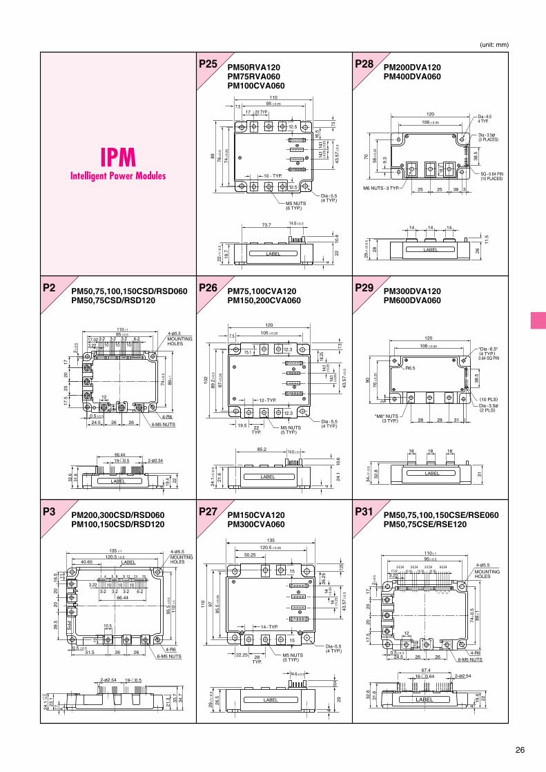
P2
P3
P26
P27
P29
P25 P28
P31PM200,300CSD/RSD060PM100,150CSD/RSD120
PM50,75,100,150CSD/RSD060PM50,75CSD/RSD120
PM50RVA120PM75RVA060PM100CVA060
PM75,100CVA120PM150,200CVA060
PM150CVA120PM300CVA060
PM200DVA120PM400DVA060
PM300DVA120PM600DVA060
PM50,75,100,150CSE/RSE060PM50,75CSE/RSE120
IPMIntelligent Power Modules
M5 NUTS(6 TYP.)
Dia - 5.5(4 TYP.)
95�0.257.5
110
89
22+
1/-0
.5
19.7
76�
0.5
74�
0.25
20 TYP.17
43.5
7�0.
314.1
�0.
2514
.1�
0.25
16.5
7.5
10 - TYP.
12.5
12.5
22
4
10.6
73.7 14.6�0.3
LABEL
M5 NUTS(5 TYP.)
Dia - 5.5(4 TYP.)
105�0.257.5
120
22TYP.
19.5
14.1
�0.
2514
.1�
0.25
18.2
5
7.5
43.5
7�0.
3
12.3
12.3
12 - TYP.
85.2 14.6�0.3
10.6
4
24.1
15.1
87�
0.25
89.2
�0.
5
102
24.1
+1/
-0.5
21.6 LABEL
LABEL
M5 NUTS(5 TYP.)
Dia -5.5(4 TYP.)
120.5�0.25
135
28TYP.
22.25
26.2
514
�0.
2514
�0.
25
43.5
7�0.
37.2
5
14 - TYP.
50.25
110
10.4
29
4
9729
+1/
-0.5
26.5
15
15
95.5
�0.
25
14.6�0.3
106�0.25
120
70
28 26
11.5
9.3 38
.5
56�
0.25
29+
1.0/
-0.5
3382525
LABEL
M6 NUTS - 3 TYP.
14 14 14
Dia - 6.54 TYP.
SQ - 0.64 PIN(10 PLACES)
Dia - 3.5�(2 PLACES)
18.3
"Dia - 6.5" (4 TYP.)0.64 SQ PIN
"M8" NUTS(3 TYP.)
(10 PLS)
106�0.25
76�
0.25
3
34+
1/-0
.5
32.8
3138
.5
90
120
3312828
18 18 18
Dia - 3.5� (2 PLS)
R6.5
LABEL
1615
1413
1211
1097 8654321
MOUNTINGHOLES
10
12
16-�0.64
31.6
2-�2.54
32.6
110�1
95�0.5
24.5
17.5
0.5�0.3
3.22
2�0.
5
17
74�
0.5
89�
14
19.4
67.4
22
2626
2020
17.022-2.54 2-2.54 6-2.542-2.54
4-R6
6-M5 NUTS
4-�5.510.16 10.16 10.16
LABEL
103-2 3-2 6-2
4-�5.5
6-M5 NUTS
4-R6
3-210 10
17.02
2020
26 26
22
66.44
19.4
4
89�
1
74�
0.5
17
2�0.
5 3.22
0.5�0.3
17.5
24.5
95�0.5
110�1
32.6
2-�2.54
31.6
19-�0.5
12
10
MOUNTINGHOLES
LABEL
16.5
135
MOUNTINGHOLES40.65
3.22 103-2 3-2 3-2 6-2
10
66.44
10
1120
2039
.5
�1
1 4 5 8 9 12 13 19
95.5
�0.
5
110
�1
120.5LABEL
4-�5.5
2-�2.54
�0.5
0.551.5 26
10.5
13
23.1
7.7
4
26
21.3 33
.734
.7
4-R6
6-M5 NUTS
�0.3
24.1
–0.5
+1.0
PP
S
19-�0.5

27
P32
P35
P37
P36
P38PM50,75,100,150CL1A/RL1A060PM25,50,75CL1A/RL1A120PM50,75B4/B5/B6LA060
PM50,75,100,150CL1B/RL1B060PM25,50,75CL1B/RL1B120PM50,75B4/B5/B6LB060
PM200,300CLA/CL1A/RL1A060PM100,150CLA/CL1A/RL1A120
PM200,300,450CLA120PM450,600CLA060
P39 PM50RL1C060PM25RL1C120
P40 PM50,75,100,150,200CS1D060PM25,50,75,100CS1D120
PM200,300CSE/RSE060PM100,150CSE/RSE120
10.5 10.5
10.5
10.5
78�
0.5
6.05
6.05
34.7
33.6
24.1
+1 –0
.510
.5 21.5
18.7
20 110
2016
.5
71.5
3.25
2-�2.5
4-�5.5MOUNTINGHOLES
19-�0.5
6-2
19 13 9 5 1
1130.15
3-2 3-2 3-2 3.2510 10 10
66.5
26
1811
26
135
110�0.56.05
6-M5NUTS
6.0540.5 11.7
10.5
LABEL
106
19.753.25
7
16 15.25 2-�5.5MOUNTINGHOLES
6-M5NUTS
6-23-23-23-2
10.75
712
(SCR
EWIN
G D
EPTH
)
19-�0.5
32.75 23 23 23
13
3155
11.75
3213
.5
17.5
17.5
19.75
12
14.5
1616
12011
1 5 9 13 19
12
16.5
135
39.7
3.22 10.16 10.16 10.16
2-2.54 2-2.54 2-2.54 6-2.5467.474.4
11
2020
39.5
�1
1 2 3 4 5 6 7 8 9 1011
1213
1415
16
95.5
�0.
5
110
�1
120.5LABEL
4- �5.5MOUNTINGHOLES
2-�2.54 16-�0.64
�0.5
51.5 26
10.5
13
4
26
21.3 33
.734
.7
4-R6
6-M5 NUTS
0.5�0.3
24.1
+1.
0–0
.5
35.5
36.6
12 7
1 6
13 36
9.08
21 3-2.54
50
53.75 50 53.75
31.843-2.543.22
50
21 3-2.54
31.843-2.543.22
21 3-2.54
31.843-2.543.22
17
12
17
12
17
12
17
12
17
12
17
12
162
172
50�0.5614 22 28 22 2228
50�0.5 50�0.5
11
8-�5.5MOUNTINGHOLES
6-�2.5
12-M6NUTS
94.5
7.75
55
3.75
(15.
5)
150
137
123
110�
0.5
99
20
13.5
5.5
6.5
24-�0.64
227.75 98.25
2.5232323
19.5
5525
.75
25
19-�0.5
9.5
11.5
27.5
106�0.25
66.519.753.25
7
44
354
4
44 44 44 44
16 15.256-23-23-23-2
1616
120
1 5 9 13 19
4-�2.5
2-�5.5MOUNTINGHOLES
13951
2320
.5
25
50
2
13
25
2- �4.3MOUNTINGHOLES
16.5
90
5 10 2 2 2 10 2 2 2 10 2 2 2 10 2 2 2 2 2 2
12 12 12 12 1210
80
LABEL
5-M4 NUTSCREWINGDEPTH 7.5
23.79 2-2.
54
2-2.
54
2-2.
54
5-2.5410.16 10.16
15
3
197
19 19 19
10.16
106 ±0.3
28 6.5
211
.61.
1
10
16.5
30
7
120
1 4
9
67.4
5.5750 398.
52.
525
1.65 7 10 15
31.2 42
.7
LABEL
2-�5.5MOUNTINGHOLES
2-R7
15-�0.64

28
(unit: mm)
H106 CM400HA-24ACM600HA-24A,-5FCM600HN-5F
H107 CM600HB-24A
IGBT ModuleInsulated Gate Bipolar
Transistor Modules
CM600HU-12H,-12FCM400HU-24H,-24F
U101
U111 CM50E3U-24HCM75E3U-12H,-24HCM100E3U-12H,-24NFCM150E3U-12HCM200E3U-12NF
CM600HU-24H,-24FU102 U201
U112 CM150E3U-24HCM300E3U-12H
CM100DU-34KACM150DU-24H,-24F,-34KACM200DU-24H,-24F,-24NFHCM300DU-12H,-12F,-12NFH,-24NFHCM400DU-5F,-12H,-12F,-12NFH
H105 CM450HA-5F
93�0.25
108
16
29
6
7.9
17.57.5
10
2025
.8+
1/-0
.5
36+
1/-0
.5
9
10 1348 62
Dia - 6.5(4 TYP.)
24 20
(8.5
)
M6 - THD.(2 TYP.)M4 - THD.
(2 TYP.)
LABEL
CM
20
24.5
2062
�0.
25+
1.0
–0.5
93�0.25
2-M4 NUTS
L A B E L
2-M8 NUTS
4-�6.5MOUNTINGHOLES
110
13 21 29 17.5
80
35+
1.0
–0.5
107
2613.5
62
26+
1/-0
.5
34+
1/-0
.5
9.5
10
12.5
5
48�
0.25
Dia - 6.5(4 - MOUNTINGHOLES)
29
2 - M4 NUTS 2 - M8 NUTS
20.5
93�0.25
LABEL
94
23
24
114
48 13
7.5
21.2
30+
1/-0
.5
4
17
2 - MOUNTINGHOLES (6.5 Dia.)
723
3 - M5 NUTS
80�0.25
13.512
16 16252.5
LABEL
2.5 2.5 TAB#110,t=0.5
110
LABEL
24.513.5
80
26+
1/-0
.5
34+
1/-0
.59.
5
14.5
5.5
62�
0.25
Dia - 6.5(4 - MOUNTINGHOLES)
29
2 - M4 NUTS2 - M8 NUTS
21.5
93�0.25
93�0.25
48�
0.25
TAB#110,t=0.5
29+
1.0
–0.5
4-�6.5 MOUNTING HOLES
LABEL
3-M6 NUTS
108
62
18 7 18 7 18
8.5
224
610
.515
.85
14
18
8.25
14 14
25 2.521.525
93�0.25
48�
0.25
TAB#110,t=0.5
29+
1–0
.58.
858.
25
4
4-�6.5 MOUNTING HOLES
3-M6 NUTS
108
62
18 187 7 18
8.5
22
2.8
4
7.5
615
67
17.5
14 14 14
25 2.521.525
Tc MEASURED POINT
7.57.5
LABEL
25.7
18
LABEL
97
80
2926.5
6
6.7Dia-6.5.(2 TYP.)
M6-THD.(2 TYP.)
9
16 48
13
29+
1/–
0.5
36+
1/–0
.5
13
M4-THD.(2 TYP.)
17.5

29
U204
U203 CM50DU-24H,-24FCM75DU-12H,-24H,-12F,-24FCM100DU-12H,-24H,-12F,-24F,-24NFHCM150DU-12H,-12F,-24NFHCM200DU-12H,-12F,-12NFH
CM400DU-24F
CM100DUS-12FCM150DUS-12F
U206 CM600DU-12NFHCM400DU-24NFHCM600DU-24NFH
U205 CM300,400DU-34KACM600DU-24F,-24NF
U601 CM50TU-24H,-24FCM75TU-12H,-12FCM100TU-12H,-12F
U401 CM75,100BU-12H
U602
N201 CM75DY-34ACM100DY-24NF,-24A,-34ACM150DY-12NF,-24NF,-24ACM200DY-12NF,-24ACM300DY-12NF
CM75TU-24H,-24FCM100TU-24H,-24FCM150TU-12H,-12FCM200TU-12H,-12FCM50,75TU-34KA
U202 CM200DU-34KACM300DU-24H,-24FCM350DU-5FCM600DU-5F
140130
110�0.25
20
1020
.414
.5
9
14.5
408
130
110�
0.25
65
36
3–M8 NUTS 4–M4 NUTS
43.8 13.8 11.510
26 26 26
15
15
4–�6.5MOUNTING HOLES LABEL
35+
1–0
.5
24.5
+1
–0.5
94
2317
24
4830
+1/
-0.5
421
.2
4
7.5
1118
2 - MOUTINGHOLES (6.5 Dia.)
723
3 - M5 NUTS
80�0.25
13.512
16 1625
LABEL
2.5 2.52.5 TAB#110,t=0.5
140130
110�0.25
20
1020
.414
.5
9
14.5
408
130
110 �
0.25
65
36
3–M8 NUTS 4–M4 NUTS
43.8 13.8 11.510
2626 26
15
35+
1–0
.5
24.5
+1
–0.5
15
4–�6.5MOUNTING HOLES LABEL
3-M6 NUTS
4-�6.5 MOUTINGHOLES
LABEL
(8.5)
(22.
2)
9.25
(10)
(8.5)
(9)
(9)
93�0.25
62�
0.25
110
17.5
18.2
5
80
615
6
29+
1.0
–0.5
21.2
8.5
25
18 18 187 7
14 14 14
25 21.5
TAB#110. t=0.5
102
Dia - 5.5(4 - MOUTINGHOLES)
80�0.25
11
10
74�
0.25
1.25
268.
1
39.3
18.7 1.
25
91
20
10
11 11 11.8519.1 19.1
11 11 11
TAB#110,t=0.5
TAB#110,t=0.5
3.05
19.1 19.1
20 20
LABEL
5 - M4 NUTS
11 1119.1 14.4
17.520
55�0.25
10
Dia - 5.5(4 - MOUTINGHOLES)
4 - M4 NUTS 10
0.5
8.1
1639
.318
.71.
251.
25
26
91
74�
0.25
10.5
17.520
11 19.1
155
LABEL
41
15
72
TAB#110,t=0.5
80�0.25
94
48 13
47.
521
.218
4
121212
2323 1717
2-�6.5 MOUNTING HOLES
3-M5 NUTS
7716 16 16
LABEL
29+
1.0
–0.5
5 - M5 NUTS
17
3.75
3.75
8.1
26
Dia - 5.5(4 - MOUTINGHOLES)
48.5
11
80�
0.25
102
11
12 12
90�0.25
23
1121.7 21.7 14.4
107
11 11 1121.7
23
21.70.8
23
LABEL
TAB#110,t=0.5
3-M6 NUTS
4-�6.5MOUTINGHOLES
LABEL
(8.2
5)
18.2
5(18.
5)
62�
0.25
80
110
93�0.25
2.521.5
615
6
1414
29
18718718
14
218.
5
7.5
2.8
4
25 25
+1.
0–0
.5

30
(unit: mm)
N203
N204
CM300DY-24NF,-34ACM400DY-24NF,-24ACM600DY-12NF,-24A
CM900,1400DU-24NFCM1000DU-34NF
N205 CM400DY-34A
NF601 CM50TL/RL-24NFCM75TL/RL-12NF,-24NFCM100TL/RL-12NF,-24NFCM150TL/RL-12NF
NF602 CM150TL/RL-24NFCM200TL/RL-12NF,-24NF
NX101 CM400HX-24ACM600HX-12A,-24A
NX201 CM150DX-24ACM200DX-24ACM300DX-12A,-24ACM400DX-12ACM450DX-24A
NX701 CM75RX-24ACM100RX-12A,-24ACM150RX-12ACM200RX-12A
N202 CM150DY-34ACM200DY-24NF,-34ACM300DY-24ACM400DY-12NF
8-�6.5MOUNTINGHOLES
74�
0.25
74�
0.25
129.
516
6
42.5
�0.
2538
�0.
2519
42
150137.5�0.25
12 21414
21
15.7
18
42 421414 141414 14
15.7
1138
�0.
255.
5
10.5
25.1LABEL
9-M6 NUTS 12
62�
0.25
80
25 25 21.5
4-�6.5 MOUNTING HOLES
8.5
21.2
7718
14 14 14
18 18TAB#110,t=0.5
3-M6 NUTS
LABEL
29+
1.0
–0.5
615
6
93�0.25
110
36 43.8 13.8 11.510110�0.2
1013010
130
1010
20.5
14.5
4014
.511
0�0.
2
99
920
9
(25.9) (15)
4-�6.5
24.5
+1
–0.5
35+
1–0
.5
2-�5.5
5511
.75
32(1
3.5)
106�0.5
13.62
7
17 1740.78
12011
6-M5NUTS
35
(19.75)
10.75
22 23 23 23
16
3 23.212
22 (SCR
EWIN
G D
EPTH
)
12
1212
12 12 12
+1
–0.5
MOUNTINGHOLES
2020
16.5
18
110�0.5(6.05) (6.05)
11.7262617.5
135
10.5
10.5
18.7
110
10.5
10.5
10.5 10.5
(13)
48.7
5
13.7
526
.5
4
4-�5.5
78�
0.5
(6.0
5)
2530.5 25 (13)
1146.3
13
24.1
(SCR
EWIN
G DE
PTH)
6-M5 NUTS
(6.0
5)+
1–0
.5
LABEL
MOUNTINGHOLES
�1
8.8
�4.
2
�1
5
(102
.25)
�9
5
�7
2.1
4�
68
.33
(7.7
5)
3.5
22(1
4)(1
4)
(13.5) (13.5)
121712 6
6
17
121.7
110�0.5
50�
0.5
6257.5
39
9994.5
137152
6.5
(21.14)
4-M6NUTS
(5.4
)12
.5(S
CREW
ING
DEP
TH)
0
LABEL
46
47
48
24
23
22
25
1
4-�5.5MOUNTINGHOLES
17+
1–0
.5
46
47
48
24
23
22
25
1
4-�5.5MOUNTINGHOLES
�18.8
�15
�45.4
8�
41.6
6
(102
.25)
�95
�72.1
4�
68.3
4
(7.7
5)
3.5
22(1
4)(1
4)(4
.2)
(13.5) (13.5)
�58
.4
121712 6
6
17
121.7
110�0.5
50�
0.5
6257.5
39
9994.5
137152
6.5(21.14)
4-M6NUTS
(5.4
)12
.5(S
CREW
ING
DEP
TH)
0
LABEL
17+
1–0
.5
22 3914
6.5
1217
13.5 20.71 22.86 22.86 22.86
6-M5NUTS12 17
6 8.5
12 66
17
13.6
4
(21.
14)
6.5
(21.14)
121.7110�0.5
50�
0.5
77.16257
.5
39
9994.5
136.9
34
35
36
13
12
51 2 43
4-�5.5MOUNTINGHOLES
0.8
3.5
�114.0
6(1
10)
(102
.25)
�95
�91.2
�79.7
6�
75.9
6
�64.5
2�
60.7
2
�49.2
8�
45.4
8
�34.0
4�
30.2
4
�18.8
�15
(7.7
5)
(20.
5)
0
LABEL
48�
0.25
62
21.5 25 25 24
4-�6.5 MOUNTING HOLES
8.5
22.2
771814 14 14
18 18TAB#110,t=0.5
3-M6 NUTS
LABEL
30+
1.0
–0.5
615
6
93�0.25
108
�0.5� All dimensions with a tolerance of
�0.5� All dimensions with a tolerance of
�0.5� All dimensions with a tolerance of
31
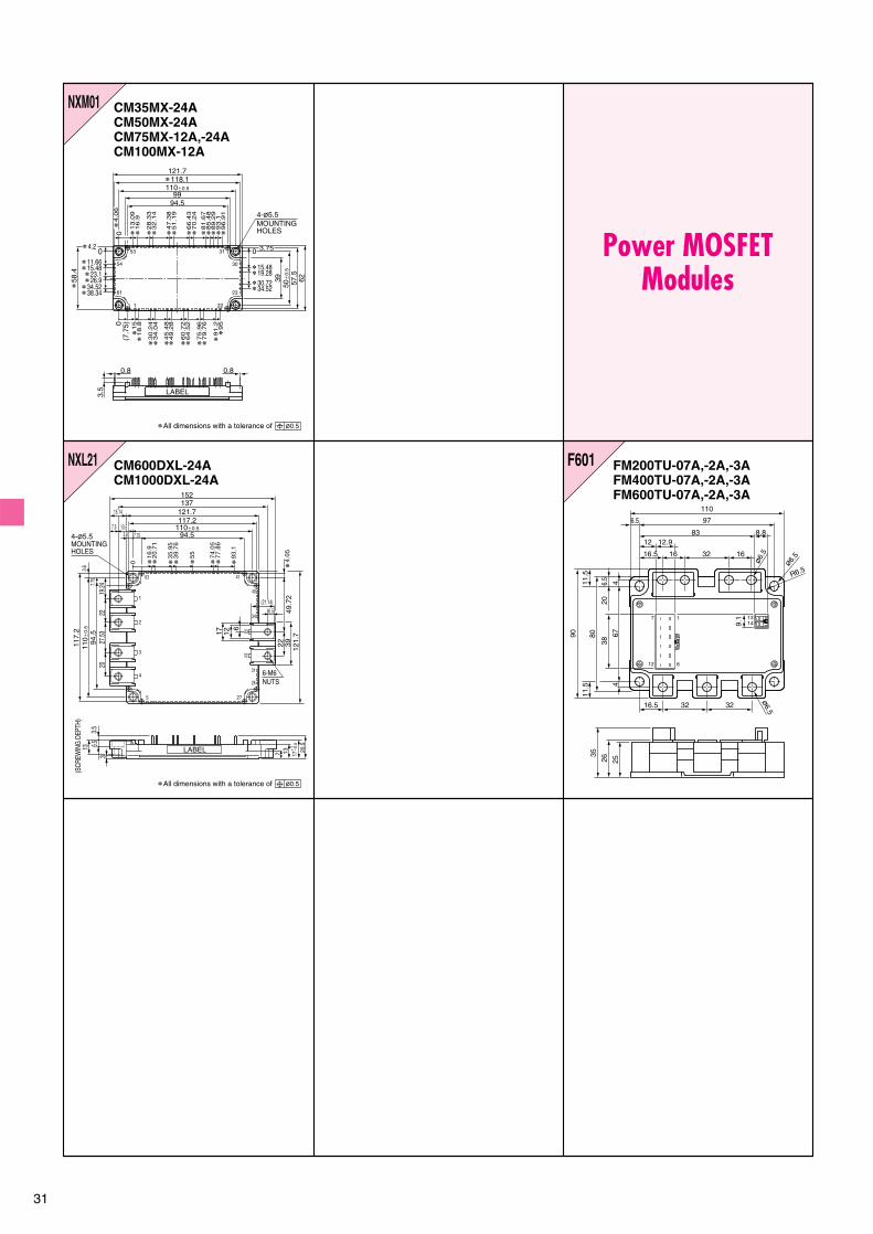
F601 FM200TU-07A,-2A,-3AFM400TU-07A,-2A,-3AFM600TU-07A,-2A,-3A
Power MOSFETModules
NXM01 CM35MX-24ACM50MX-24ACM75MX-12A,-24ACM100MX-12A
NXL21 CM600DXL-24ACM1000DXL-24A
11.5
9.1
110
97
83 8.812 12.9
16.5 16 1632
1 1314
7
612
6.5
11.5
35
26 25
16.5 32 32
6.5
20
44
67
38
90 80
R6.5
�6.
5
�6.
5
�6.5
53
54
61
1 22
31
30
23
99
121.7� 118.1110�0.5
94.5
�58
.4
0
0.8
3950
�0.
5
57.5
62
� 4.2
� 15.48� 11.66
�4
.06
�1
3.0
9�
16
.9�
15
�1
8.8
�3
0.2
4�
34
.04
�4
5.4
8�
49
.28
�6
0.7
2�
64
.52
�7
5.9
6�
79
.76
�9
1.2
�9
50(7
.75)
�2
8.3
3�
32
.14
�6
6.4
3�
70
.24
�8
1.6
7�
85
.48
�8
9.2
9�
93
.1�
96
.91
� 15.48� 19.28� 30.72� 34.52
�4
7.3
8�
51
.19
� 26.9� 23.1
� 38.34� 34.52
0 0 3.75
0.8
3.5 LABEL
4-�5.5MOUNTINGHOLES
4-�5.5110�0.5
121.
7
117.
2
94.5
7.75
3.6
27.5
320
2219
.24
49.7
23922
20.5
137
61217
110 �
0.5
MOUNTINGHOLES
152137
121.7117.2
94.5
15.14
7.57.75
63 41
33
40
34
32
28
31
1
2
3
4
5 27
�16.9
�20.7
1
0 �35.9
5�
39.7
6
�74.0
5
�55
�77.8
6
�93.1
�4.0
5
(21.14)6.5
6-M6NUTS
17+
1–0
.5
LABEL
3.5
13 6.53
(SCR
EWIN
G D
EPTH
)
13.53.6
�0.5� All dimensions with a tolerance of
�0.5� All dimensions with a tolerance of

32
(unit: mm)
R3
R4 RM25HG-24SRM50HG-12SRM35HG-34S
R1 RM250HA-10FRM300HA-24F
RM400HA-24SR6
R7 RM200DA-20F,-24F
R5R2 RM20HA-12F,20F,-24F R8 RM500HA-M,-H,-24,-2H
RM50HA-12F,-20F,-24FRM100HA-12F,-20F,-24F
RM100C1A-12F,-20F,-24FRM100CA-12F,-20F,-24FRM200HA-20F,-24FRM20C1A-6S,-12F,-12S,-20F,-24FRM20CA-6S,-12F,-12S,-20F,-24FRM20DA-12F,-12S,-20F,-24FRM50C1A-6S,-12F,-12S,-20F,-20S,-24FRM50CA-6S,-12F,-12S,-20F,-20S,-24FRM50DA-12F,-12S
R6
53.5
43.38
99
14
5.3
36.5
3323
.5
4.5 29
�5.3 3-M4
LABEL
6.35�4.2
R2.1
0.8
7.0
19.530.239.0
3.7
7.0
0.4
0.4
4.2
24
�1.7�2.4
3.2
9
24
6.35
0.8
LABEL
6.35
LABEL
22 46
2-�5.535
65
80
2
17
2-M8
30
9
64 65
3
14.5 14.5
67.580
15 35
20 25.5
29.5
2-�5.4 2-M6
LABEL
Mark
�3.2�0.2
6�
0.2
26�
0.5
2.5
2.5�0.3
2�0.3
5.45�0.5
1�0.2
5.45�0.5
3�
0.3
93�0.3
16
29
4-�6.5
48�
0.3
2-M6
LABEL
(93)
25 25 21.5
( 48)
62�
0.5
3 17 8 17 8 17 3
23
37
LABEL
4-�6.5
3-M6
53.543.316
�5.3 8 3-M4
R6
18 14
5.3
36.5
333.5 3.5
24 4.5
227
LABEL
108 MAX.
36 M
AX
.
41.5
MA
X.
62 M
AX
.
30 M
AX
.
20.5 MIN.
20 M
IN.
92.2 MAX.
27.5
MAX
.Diode Modules

33
R12
R13R10
R9 R15
R16
R14R11 R17
RM500DZ-M,-H,-24,-2HRM500UZ-M,-H,-24,-2H
RM10TA-M,-H,-24,-2HRM15TA-M,-H,-24,-2H
RM30CZ-24,-2HRM30DZ-24,-2HRM50D2Z-40RM100D2Z-40
RM30CZ-M,-HRM30DZ-M,-HRM60CZ-M,-H,-24,-2HRM60DZ-M,-H,-24,-2H RM100CZ-M,-H,-24,-2HRM100DZ-M,-H,-24,-2H
RM20TA-24,-2H
RM30TA-M,-H
RM15TC-40RM30TC-40
RM150CZ-M,-H,-24,-2HRM150DZ-M,-H,-24,-2HRM150UZ-M,-H,-24,-2HRM250CZ-M,-H,-24,-2HRM250DZ-M,-H,-24,-2HRM250UZ-M,-H,-24,-2H
RM30TB-M,-H
93.580
17.5 20 203-M5
2-�6.512
.5 26
6.5
21 30LABEL
93.580
12.5
26
2 -�6.5
3-M516.5 23 23
6.5
2130LABEL
620
3 -�6.54-M8
40
18 16 18 16
30 32 30
150
68.5 68.5
7
23 32 392
LABEL
LABEL
60 50 36 16
24 24 24 24
23 35 35
80�0.2 80�0.2
180
3-�6.54-M8
36 44 50
44
LABEL
3022 12 12 12 (22)
13
R12.536880
29
2-�6.5
4
218
.5 31LABEL
TAB#250, t=0.8
25 25
10 10 10 4-�4.5
5-M4
1313
33
10 10285075
90 78 66
31.5
6.5
15 15
R13
1.1 15 1.167
80
9.5
12.5
40
TAB#250, t=0.8
5
2033 36
LABEL
2-�6.5
14.5 28
10 2-�4.5
20 40
5 -M413.5 15 168
57
70
6
22 24LABEL
17.5 17.5
105-M5
2-�6.5
40
3
186780
20
5 25
35
LABEL

34
(unit : mm)
R21
R22R19
R18
R23R20
R24
R25
RM20TPM-2H,-24
RM75TPM-M,-H,-24,-2HRM75TC-M,-H,-24,-2H
RM30TC-24,-2H RM50TC-M,-H,-24,-2H
RM450HA-5HRM20TPM-H,-MRM30TPM-H,-M
RM10TN-2HRM20TNA-HRM25TN-2HRM30TNA-H
RM300CA-9W
Mark17.5
�0.
5
11.5
12.08 1.2�0.5�0.1
40.64�0.5
� � � � �
10.16�0.25
5�4
71.8�1
64.8�0.5
56.230
�1
13.7 5
514
2-�4
2-R4
0.6
1.5
� � �
20 20
11.5
10.5
40
2-�5.5
105-M530
6880
8
26.5
29.5
LABEL
23 23
14 14 14
90 78 66 32
2020
5 -M6 4-�4.5
16 16
305074
316.
5
20 20
3
11.5
10.5
40
2-�5.5
5-M530
68�0.25
80
8 24.1LABEL
LABEL10
+15
-0.5
40201822
�1
6
2-�4.5MOUNTINGHOLES
5-M4 NUTS
13.5 15 158
7057�0.25
14.5 2810
LABEL
402018
2622
�1
6
2-�4.5MOUNTINGHOLES
5-M4 NUTS
13.5 15 158
7057�0.25
14.5 2810
LABEL
9780�0.25
29
(8)(10.5)
17.5
2-M6NUTS
48( 16)
2-�6.5MOUNTINGHOLES
LABEL
36+
1–0
.5
41�
0.25
( 19.
4)
55
4-R7
( 7) ( 2
8.5)
30+
1–0
.5
(18)
30 30
3-M8 NUTS
4-�5.5 MOUNTING HOLES
86�0.25
100
LABEL
Stamp

35
T3
T4T1 TM400HA-M,-H,-24,-2H
T5 TM130CZ/DZ/EZ/GZ/PZ/RZ-M,-H,-24,-2HTM200CZ/DZ/EZ/GZ/PZ/RZ-M,-H,-24,-2H
T2 TM20DA-M,-H
TM400CZ/DZ/PZ/UZ-M,-H,-24,-2HT6
TM20RA-M,-HT7
T8
TM25CZ/DZ-M,-HTM55CZ/DZ-M,-HTM90CZ/DZ-M,-H
TM25CZ/DZ-24,-2HTM55CZ/DZ-24,-2HTM90CZ/DZ-24,-2H
TM25EZ/RZ-M,-HTM55EZ/RZ-M,-HTM90EZ/RZ-M,-H
LABEL
22 46
2 - �5.535
65
80
2
17
2 - M8TAB#110, t=0.5
730
9
64 65
93.580
17.5 20 20 3 - M5
2 - �6.5
2612.5
TAB#110,t=0.5
30
216.5
9
LABEL
8.51536 4 - M4
13 18 32
2 - �5.560
47.6
TAB#110, t=0.5
11
2.0
16.5 24
.5 30
LABEL
93.580
16.5 23 23 3 - M5
2 - �6.5
2613
TAB#110,t=0.5
30
216.5
9
LABEL
3 - �6.54 - M8
18 16 18 16
32 30
68.5
30
68.5
150
TAB#110,t=0.5
40
3932
23
7
206
9
LABEL
16365060
24
3626
3 -�6.5
4 - M824 24 24
2635443523
80�0.2 80�0.2
180
TAB#110, t=0.5
936 50
9
LABEL
8.5
1536
4 - M4
13 18 32
2 -�5.5
6047.6
TAB#110, t=0.5
11
2.0
16.5 24
.5 30
LABEL
93.580
17.5 20 20
3 - M5
2 - �6.5
2612.5
TAB#110,t=0.5
30216.5
9
LABEL
Thyristor Modules

36
(unit: mm)
T12T9
T13T10 TM10T3B-M,-H
T14 TM150SA-6T11
TM60SA-6TM90SA-6
TM25EZ/RZ-24,-2HTM55EZ/RZ-24,-2HTM90EZ/RZ-24,-2H
TM60SZ-MTM100SZ-M
TM15T3A-M,-HTM25T3A-M,-H
93.580
16.5 23 23 3 - M5
2 - �6.5
2613
TAB#110,t=0.5
30
216.5
9
LABEL
31 27
62 4520
20
4 - �5.561.7
74
86
TAB#110, t=0.5 5 - M5
316
722LABEL
3 - �65718 20 20 12 - �6.5
13 26
8093.5
TAB#110,t=0.5
4 2.2
6.5
199
4156
LABEL
3 - �9.0
TAB#110, t=0.5
20.5 26 26
3413
4 2.5 4
93108
2.5
2 - �6.5
2 - ø1.0
6045
1221
8
LABEL
4
2 2
80
2 - �4.5
347
2
18.5
2231
7.5
68
17 17
TAB#250, t=0.8TAB#110, t=0.5
LABEL
6
93.580
17.5 20 20 3 - M5
2 - �6.5
26
12.5
TAB#110,t=0.5
30 M
AX
.21
6.5
9
LABEL

37
PM 1200 H CE 330 -1 (TYPE 1)CM 1200 H C -66 H (TYPE 2)FG 4000 G X -90 DA (TYPE 3)GCU 15 CA -130 (TYPE 3)
Type of device
Rated current capacity(however, the GCT thyristor unit isshown as a value multiplied by 1/100.)
Connection
Auxiliary number (denotes the type of outline ormanufacturing process)
Voltage classification or turn-offtime or high-frequency type incase of "x"
Voltage classFor TYPE 1:
Withstand voltage class � 10 = VCES
Example: 330 � 10 = 3,300 VFor TYPE 2:
Withstand voltage class � 50 = VCES
Example: 66 � 50 = 3,300 VFor TYPE 3:
Withstand voltage class � 50 = VDRM or VRRM
Example: 90 � 50 = 4,500 V
Series code
High-power devices are semiconductor devices represented by gatecommutated turn-off (GCT) thyristors and high-voltage insulated-gatebipolar transistor (HVIGBT) modules, and these devices are now used inequipment designed for traction, including high-speed express trains, andin power system equipment.We offer a variety of high-power devices to suit diversified applications.These devices include diodes, thyristors, GTO thyristors, GCT thyristors,HVIGBT modules, and high-voltage intelligent power modules (HVIPM).
High-powerdevices
Thyristors
GCTthyristors
unit
GTOthyristors
Rectifierdiodes
High-voltagediode module
High-voltageIPM
High-voltageIGBT module
200 to 1800A 1700 to 6500V
GCU 400 to 1500A / 6500V
HVDi
General-purpose 800 to 5000A 500 to 5000V
500 to 3000A 2800 to 6000VHigh-speed switching
General-purpose 1000 to 5000A 400 to 12000V
800 to 1500A 1200 to 2500VHigh-speed switching
GTO 1000 to 6000A 2500 to 6000V
1200A 3300VHVIPM
200 to 2400A 1700 to 6500VHVIGBT
� Types and symbols
Stud or flat base Flat Module Type
SR FD — 3
CR FT — 3
— FG — 3
— GCU — 3
— — CM 2
— — PM 1
— — RM 2
General-purpose rectifier diode /High-speed switching rectifier diode
General-purpose thyristor /High-speed switching thyristor
GTO thyristor
GCT thyristor unit
HVIGBT module
HVIPM
HVDi module
Symbol Outline
Type of device
� Naming system
High-power DevicesLarge Product Variety for Wide-Ranging Needs

38
GTO / GCT Thyristors and HVIGBT Module Series
High-power modules are used in various installations, such as tractions, power supply systems, and other large-capacity industrial equipment.In today's market, there are increasing demands for these modules to have enhanced withstand voltage and capacity together with lower power loss.The established series of Mitsubishi Electric diodes, general-purpose thyristors, GTO thyristors, GCT thyristor units, and high-voltage insulated-gate bipolartransistor (HVIGBT) modules meet a variety of customer needs. We are also actively engaged in improving existing modules and developing new products.
� Main circuit of PWM converter/inverter system
M
3-phaseAC powersupply
PWM converter Filter circuit PWM inverter unitR-phase S-phase T-phase U-phase V-phase W-phase
3-phase inductionmotor
DCreactor
Capacitor
1.0 2.0 3.0 4.0 5.0 6.0 7.00
1.0
2.0
3.0
4.0
5.0
6.0
7.0
VD
RM
/VC
ES
(kV
)
ITQRM / ICM (kA) �1�1: lCM = lC � 2�2: "H" denotes the single type, "D" denotes the dual type, and "E" denotes the chopper type
: De-alloy GTO Series (DA Series)
: HVIGBT module SeriesHVIPM Series
: GCT thyristor unit Series
�2Main tractioninverter
Motor control
HD H
HDEHDDE H H H
HHD HE
HH
HH HE
H
Paper millSteel millSVG
� GCT thyristor Series(Gate Commutated Turn-off thyristor)
The GCT thyristor is high-power device that takes the placeof existing GTO thyristors. Because the turn-off capabilityhas rapidly improved, and the turn-off time shortened toabout 1/10 of GTO thyristors, it is most suitable forapplications which require series connection.Because the GCT thyristor can be turned-off using only theclamping circuit, even if there is no snubber circuit like thatrequired by the GTO thyristor, low-loss, small size andlighter equipment are achieved.
� HVIGBT modules(High Voltage Insulated Gate Bipolar Transistor module)
HVIGBT modules are manufactured in an exclusive assembly lines understrict quality control. Use of aluminum silicon carbide (AlSiC) base platesenables improved reliability and extended service life for these modules.With a line-up of high withstand voltage modules in the voltage range of1.7kV to 6.5kV, the highest level in the world, Mitsubishi Electric is ready tomeet various customer needs for applications in tractions and other large-scale industrial installations.The newly-developed N Series HVIGBT modules are equipped with CSTBTTM
chip that allows lower power loss and the minimization of package size.Mitsubishi Electric has also produced a series of "HG" modules that arehoused in a well-insulated packages and demonstrate an insulatingperformance as high as 10.2kV.

39
Rectifier Diodes
Flat type ø45Flat type ø35Flat type ø35Flat type ø50Flat type ø60Flat type ø60Flat type ø80Flat type ø85
Flat type �60Flat type �60Flat type �50Flat type �70Flat type �130
�1: Shown by the average forward current
� Rectifier diodes for fast switching (Soft recovery type)
Flat type �47Flat type �85Flat type �85Flat type �130
�1: Shown by the average forward current
� Rectifier diodes for fast switching
�1: Shown by the average forward current
FD1000A-56FD1000D-56FD1600CP-10FD1600A-60FD1600CV-80FD3500BP-12FD3500AH-56FD5000AV-100DA
800
1600
3500
5000
�
�
�
�
�
�
�
�
FD1000FV-90FD1000FX-90FD1000FH-56FD1500AV-90FD2000DU-120
800
100015001700
�
�
�
�
�
FD500JV-90DAFD1500CV-90DAFD1500AU-120DAFD3000AU-120DA
500150015003000
�
�
�
�
Current (A)�1
� Rectifier diodes for general use
TypeVoltage (V)
500 Shape600 2800 3000 4000 5000
Current (A)�1Type
Voltage (V)Shape4500 6000
Current (A)�1Type
Voltage (V)Shape2800 4500 6000

40
Thyristors / GTO ThyristorsThyristors / Gate Turn-off Thyristors
� Thyristors for general use
400
FT1000A-50FT1000BV-80FT1500DL-28FT1500CH-54FT1500DV-80FT1500GV-80FT1500AU-240FT2500CL-24FT2500BH-56FT5000AP-8
1000
1500
2500
5000
1200
�
1400
�
�
2500 2700 2800
�
�
�
4000 12000
�
��
�
Flat type �50Flat type �60Flat type �50Flat type �60Flat type �80Flat type �80Flat type �105Flat type �60Flat type �80Flat type �80
� Fast switching thyristors
1200
FT1000CY-24FT1000CX-36FT1000AX-50FT1500EX-24FT1500EY-24
�2
800
1000
1500
�
1800
�
2500
�
(15)
� (30)
� (20)
(30)(35)
Flat type �50Flat type �50Flat type �60Flat type �60Flat type �60
�1: Shown by the average ON currentNote: Numerical values in ( ) indicate the maximum shut-off time [s]
TypeVoltage (V)
Current (A)�1
Current (A)�1
Shape
TypeVoltage (V)
Shape
�1: Shown by the average ON current�2: Current type inverter thyristor
Flat type �47Flat type �63Flat type �63Flat type �70Flat type �75
�1: Shown by the repeatable control ON current
� GTO thyristors
FG1000BV-90DAFG2000JV-90DAFG2000FX-50DAFG3000DV-90DAFG3000GX-90DAFG4000BX-90DAFG3300AH-50DAFG4000EX-50DAFG4000CX-90DAFG4000GX-90DAFG6000AU-120D
100020002200
Flat type �853000
Flat type �70Flat type �85
3300
Flat type �85Flat type �85
4000
6000 Flat type �130
�
�
�
�
�
�
�
�
�
�
�
Current (A)�1Type
Voltage (V)Shape2500 4500 6000

41
GCT Thyristor UnitGate-commutated Turn-off Thyristor Unit
� FeaturesGCT thyristor units are a new product which combine the aGCT thyristor and a gate driver.The GCT thyristor is operated by an optimally designed gatedriver to obtain the highest performance based on itsperformance characteristics.
� ApplicationsThe handling of GCT thyristor units is easy because the GCTthyristor and gate driver are combined into a single unit.The GCT thyristor unit is most suitable for high-powerelectronic applications.
� Electric power applications� SVG (Static Var Generator)� BTB (Back to Back)� Frequency exchanger
� Heavy industrial applications� Motor drive for fans, pumps, steel mills and paper mills
� AC switch applications
Image of the GCT Thyristor Unit Series
� GCT units
Type Structure Control input signalSupply connectorVc
Gate driver supply
Made byPhoenix Contact Co.,Ltd.Type name:MSTB2.5/2-G-5.08AU
Symmetrical
Optical fiber data linkTransmitter: HFBR-1521:
Made byAgilent Co.,Ltd.
Receiver: HFBR-2521:Made byAgilent Co.,Ltd.
400
6500 6500 800 20V DC780
1500
125
GCU04AA-130
GCU08BA-130
GCU15CA-130
VDRM
(V)VRRM
(V)ITQRM
(A)Tj
(:)f
(Hz)Repetitive peakoff-state voltage
Repetitive peakreverse voltage
Repetitivecontrollable
on-state current
Frequency
Junctiontemperature

42
GCU04AA-130
GCU08BA-130
20V POWER SUPPLY INPUT(MSTB2.5/2-G-5.08AU)
FAULT SIGNAL OUTPUT (HFBR-1521)FIBER-OPTIC INPUT (HFBR-2521)
�38�0.2
LED
3LE
D4
LED
1LE
D2
Detail A
Detail A
3.6
1.6
13.7
20
10M
IN.
37
9MAX.
375
6�M4
�3.5�0.22.2�0.2 DEPTH
�3.5�0.22.2�0.2 DEPTH
220
170
(20)
170104
208
190
77
68 (R39.5)
A
�3.5�0.22.2�0.2 DEPTH
�3.5�0.22.2�0.2 DEPTH
20M
AX
.
120160
20
TP
GT
PK O
E1
OE
2
9
20
37
5
13.7
20
10 1.6
37
A20M
AX
. 16080
2-6�M42-6�M4
208
165
80
250 85
46.546.54848
160120160
104
140
120
K
G
K
K
G
K
G
K
G
K
G
G
�38�0.2
6�0.56�0.5
6�0.5
6�0.5 26�
0.5
�47�0.26�0.5
6�0.5
6�0.56�0.5
14.5
�1.
3
26.2
�0.
380
�0.
5
10.1
�0.
914
.3�
1.3
10.1
�0.
9
80�
0.5
�47�0.2
LED
3LE
D4
LED
1LE
D2
TP
GT
PK O
E1
OE
2
20V POWER SUPPLY INPUT(MSTB2.5/2-G-5.08AU)
CAPTIVE SCREW (M4)(HEAT SINK SIDE DEPTH 6 to 8mm)
CAPTIVE SCREW (M4)(HEAT SINK SIDE DEPTH 6 to 8mm)
FAULT SIGNAL OUTPUT (HFBR-1521)FIBER-OPTIC INPUT (HFBR-2521)
LED1: GATE OFF (RED)LED2: GATE ON (YELLOW)LED3: G-K OK (GREEN)LED4: POWER SUPPLY OK (GREEN)
GATE TEST POINTCATHODE TEST POINT
LED1: GATE OFF (RED)LED2: GATE ON (YELLOW)LED3: G-K OK (GREEN)LED4: POWER SUPPLY OK (GREEN)
GATE TEST POINTCATHODE TEST POINT
� GCT thyristor outline drawings (Unit: mm)

43
(Unit: mm)
GCU15CA-130
37
1.6
13.7
20120
Detal A
�3.5�0.22.2�0.2 DEPTH
FAULT SIGNAL OUTPUT(HFBR-1521)
FIBER-OPTIC INPUT (HFBR-2521)
20V POWER SUPPLY INPUT(MSTB2.5/2-G-5.08AU)
A
80160
20M
AX
.
120
170
WITH METAL SUPPORT PARTS
2-3�M3
165
290
32.5
32.5
85
166.
5
K
GK
G
K
G K
G
160160
208
140
104
54.554.5
80
5
37
20
9
10M
IN.
6�0.5
6�0.5
�3.5�0.2 2.2�0.2 DEPTH
6�0.5
6�0.5
6�0.56�0.5
�63�0.2
26.2
�0.
3
80�
0.5
14.5
�1.
3
10.1
�0.
9
LED
3LE
D4
LED
1LE
D2
TP
GT
PK O
E1
OE
2
K
G
K
G
�63�0.2
LED1: GATE OFF (RED)LED2: GATE ON (YELLOW)LED3: G-K OK (GREEN)LED4: POWER SUPPLY OK (GREEN)
GATE TEST POINTCATHODE TEST POINT
CAPTIVE SCREW (M4)(HEAT SINK SIDE DEPTH 6 to 8mm)
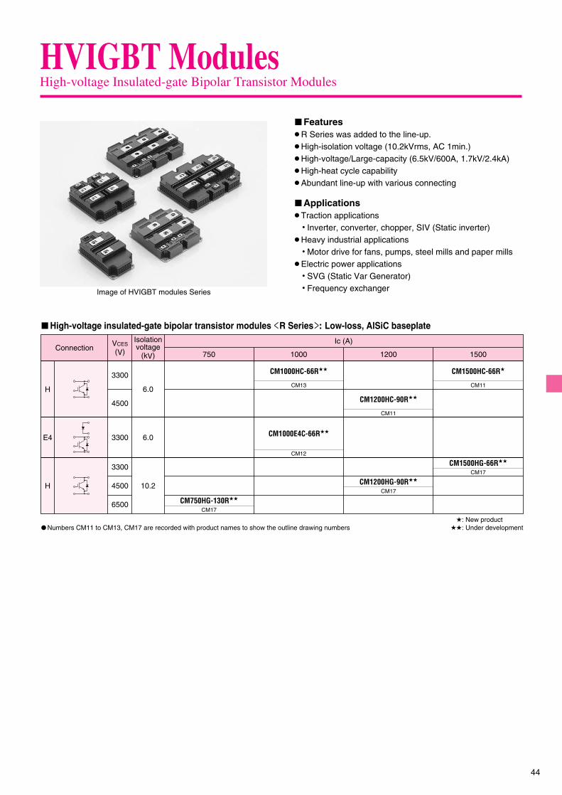
44
HVIGBT ModulesHigh-voltage Insulated-gate Bipolar Transistor Modules
� Numbers CM11 to CM13, CM17 are recorded with product names to show the outline drawing numbers�: New product
��: Under development
� High-voltage insulated-gate bipolar transistor modules R Series �: Low-loss, AlSiC baseplate
ConnectionVCES
(V)Ic (A)
1000750 1200 1500
H
CM1000E4C-66R��
H
3300
3300
4500
CM12
CM1500HC-66R�
CM11
CM1000HC-66R��
CM13
CM1200HC-90R��
CM11
E4
4500
Isolationvoltage
(kV)
6.0
6.0
10.2
6500
3300 CM1500HG-66R��
CM17
CM750HG-130R��
CM1200HG-90R��
CM17
CM17
Image of HVIGBT modules Series
� Features� R Series was added to the line-up.� High-isolation voltage (10.2kVrms, AC 1min.)� High-voltage/Large-capacity (6.5kV/600A, 1.7kV/2.4kA)� High-heat cycle capability� Abundant line-up with various connecting
� Applications� Traction applications
� Inverter, converter, chopper, SIV (Static inverter)� Heavy industrial applications
� Motor drive for fans, pumps, steel mills and paper mills� Electric power applications
� SVG (Static Var Generator)� Frequency exchanger

45
HVIGBT ModulesHigh-voltage Insulated-gate Bipolar Transistor Modules
� High-voltage insulated-gate bipolar transistor modules HG Series �: High-isolation, AlSiC baseplate
� Numbers CM4, CM7 to CM10, CM14 to CM16 are recorded with product names to show the outline drawing numbers�: New product
��: Under development
�: New product
Connection
� High-voltage insulated-gate bipolar transistor modules N Series / N Series B Type �: Low-loss, CSTBTTM chip
Connection
VCES
(V) 200 400 600 1200Ic (A)
3300
4500
6500
CM400HG-66H�
CM14
900
CM900HG-90H�
CM16
CM600HG-90H�
CM15
CM1200HG-66H�
CM16
CM600HG-130H�
CM16
CM200HG-130H�
CM14
CM400E4G-130H��
H
H
E4 6500
CM16
CM400E2G-130H��E2 6500
CM16
VCES
(V) 1200800Ic (A)
CM1200E4C-34N
CM800DZB-34N�
E4 1700
1700
1700
CM10
CM1200DB-34NCM1200DC-34N
CM9CM4
1800 2400
CM2400HC-34NCM1800HC-34N
CM10
CM2400HCB-34N�CM1800HCB-34N�
CM8CM7
CM1200HCB-34N�
D

46
HVIGBT ModulesHigh-voltage Insulated-gate Bipolar Transistor Modules
VCES
(V) 800 900 1200 1600 1800 2400Ic (A)
1700
2500
1700
3300
3300
CM1800HC-34H
CM1200HC-50H
CM1200HC-66H
CM8
CM2400HC-34HCM1600HC-34HCM1200HC-34HCM1
CM8
CM8
CM800HC-66HCM7
4500 CM900HC-90HCM8
CM800DZ-34H
CM4
CM800E4C-66H
CM8
CM800E2C-66HCM800E6C-66H
CM8
H
D
E2/
E6
1200900800600400VCES
(V)Ic (A)
2500
3300
4500
CM1200HB-50HCM8
CM1200HB-66HCM8
CM900HB-90HCM8
CM800HB-50HCM7
CM600HB-90HCM400HB-90HCM7
CM800HB-66HCM7
H
� High-voltage insulated-gate bipolar transistor modules HC Series �: Low-loss, AlSiC baseplate
Connection
Connection
� High-voltage insulated-gate bipolar transistor modules HB Series �: Low-loss, Cu baseplate
Connection
� High-voltage insulated-gate bipolar transistor modules HA Series �: Cu baseplate
� Numbers CM1 to CM8 are recorded with product names to show the outline drawing numbers
400 600 800 1200
2500
3300
1700
1700
2500
3300
1700 CM1200HA-34H
CM1200HA-50H
CM1200HA-66H
CM800HA-34H
CM800HA-50H
CM800HA-66H
CM1
CM3CM2
CM3CM2
CM600DY-34HCM4
CM600E2Y-34H
CM6
CM400DY-66H
CM400DY-50H
CM5
CM5
H
D
E2
VCES
(V)Ic (A)
E4 3300

47
CM800HA-50H,-66HCM2
CM800,1200HA-34H CM1200,1600HC-34HCM1
CM4
CM6
CM8
CM5 CM400DY-50H,-66H
CM600E2Y-34H
CM600DY-34H CM800DZ-34H CM800DZB-34N
CM1200HA-50H,-66HCM3 CM7 CM400,600HB-90HCM800HB-50H,-66H
CM1200HCB-34NCM800HC-66H
CM1200HB/HC-50H,-66HCM1800,2400HC-34H
CM800E2C/E4C/E6C-66HCM900HB/HC-90HCM1800,2400HCB-34N
130
30 140
4-M8 NUTS
6-�7 MOUNTING HOLES
11457�0.25
40
55.211.85
57�0.25
124�
0.25
20
3-M4 NUTS16
53
5 38
130
140
4-M8 NUTS
6-�7 MOUNTING HOLES
11457�0.25
61.518
5 38
57�0.25
124�
0.25
3020
16.5 2.518.5
3-M4 NUTS
4020
140
6-M8 NUTS
8-�7 MOUNTING HOLES
17157�0.25 57�0.25 57�0.25
124�
0.25
3-M4 NUTS41.2579.4
61.5 61.5
20.25
13
5 38
190
130
4020
140
4-M8 NUTS
6-�7 MOUNTING HOLES
11457�0.25
61.5
48.8
18
5 38
57�0.25
124�
0.25
5-M4 NUTS
53.6
7.236.3 24.5
130
4020
140
4-M8 NUTS
6-�7 MOUNTING HOLES
11457�0.25
10.65
61.5
48.5
18
5 38
57�0.25
124�
0.25
3-M4 NUTS10.35
LABELLABEL
LABEL
LABEL LABEL
13040 14
0
4-M8 NUTS
6-�7 MOUNTING HOLES
11457�0.25 57�0.25
124�
0.25
3-M4 NUTS10.65
48.861.5
10.35
18
5 38
20
LABEL
130
30
20
140
4-M8 NUTS
6-�7 MOUNTING HOLES
11457�0.25
55.2
53
11.85
5 38
57�0.25
124�
0.25
5-M4 NUTS
57
1640 44
18
LABEL
1906-M8 NUTS
8-�7 MOUNTING HOLES
17157�0.25 57�0.25 57�0.25
61.5 61.513
5 3840
20
140
124�
0.25
3-M4 NUTS 41.2579.420.25
LABEL
� HVIGBT modules outline drawings

48
(Unit: mm)
CM1200E4C-34N CM1800,2400HC-34NCM10
CM1200DB-34N CM1200DC-34NCM9
CM15
CM16
CM600HG-90H
CM200HG-130H CM400HG-66HCM14
CM1000HC-66RCM13
CM400E2G-130HCM400E4G-130H
CM11
CM12
CM1200HC-90R CM1500HC-66R
CM1000E4C-66R CM600HG-130HCM900HG-90H
CM1200HG-66H
4 2
3 1
20�
0.1
140�
0.5
124�
0.25
18�0.2
4-M8 NUTS
6-�7 MOUNTING HOLES3-M4 NUTS
130�0.5
57�0.25 57�0.25
40�
0.2
61.5�0.3
10.35�0.210.65�0.2
48.8�0.2
5�0.
2
38+
1–0
SCREWING DEPTHMIN. 16.5SCREWING DEPTH
MIN. 7.7
17�
0.1
140�
0.5
124�
0.25
44�
0.3
73�0.5
57�0.25
2
1
16.2�0.3
2-M8 NUTS
4-�7 MOUNTING HOLES
28.7
36
521.6�0.3 12.9�0.3
5.8
5 �0.
15
36.2
48+
1.0
0
SCREWING DEPTHMIN. 16.5
SCREWING DEPTHMIN. 4
11.85�0.2
20�
0.1
4 2
3 1
130�0.5
57�0.25 57�0.25
140�
0.5
124�
0.25
30�
0.2
55.2�0.3
6-�7 MOUNTING HOLES
4-M8 NUTS
6-M4 NUTS 18�0.216�0.2
53�0.2 57�0.2
40�0.2 44�0.2
5�0.
2
38+
1–0
SCREWING DEPTHMIN. 16.5SCREWING DEPTH
MIN. 7.7
4
3
2
1
61.2�0.5
16.5�0.3
4-M8 NUTS
17�
0.1
9�0.
1
124�
0.25
44�
0.3
130�0.5
57�0.25 57�0.25
140�
0.5
4-�7 MOUNTING HOLES3-M4 NUTS 28.5�0.5
42.5�0.3 30.7�0.5
5�0.
15
48+
1.0
0
SCREWING DEPTHMIN. 7.7
SCREWING DEPTHMIN. 16.5
38+
1.0
0
6
5
4
3
2
1
61.2�0.5 61.2�0.5
12�0.3
6-M8 NUTS
17�
0.1
9�0.
1
124�
0.25
44�
0.3
190�0.5
57�0.25 57�0.2557�0.25
140�
0.5
8-�7MOUNTING HOLES3-M4 NUTS 14�0.3 59.2�0.5
5�0.
15
48+
1.0
0
SCREWING DEPTHMIN. 7.7
SCREWING DEPTHMIN. 16.5
10.65�0.3 10.35�0.3
48.8�0.3
18�0.3
61.5�0.3
28�
0.5
5�0.
2
9�0.
2
40�
0.3
57�0.25 57�0.25
130�0.5
124�
0.25
140�
0.5
SCREWING DEPTHMIN. 16.5
6-�7 MOUNTING HOLES
SCREWING DEPTHMIN. 7.7
4-M8 NUTS
3-M4 NUTS
38+
1 0
20+
0.1
-0.
2
1
2
3
4
20.25�0.3
41.25�0.3
79.4�0.3
124�
0.25
140�
0.5
61.5�0.3
57�0.25 57�0.25 57�0.25
40�
0.3
13�0.3
9�0.
2
6-M8 NUTS
3-M4 NUTS 8-�7 MOUNTING HOLES
190�0.5
SCREWING DEPTHMIN. 16.5SCREWING DEPTH
MIN. 7.7
28�
0.5
5�0.
2
61.5�0.3
20+
0.1
-0.
238
+1
0
1
2
3
4
5
6
28�
0.5
5�0.
3
20.25�0.3
41.25�0.3
79.4�0.3
124�
0.25
140�
0.5
61.5�0.361.5�0.3
57�0.25 57�0.25 57�0.25
40�
0.3
13�0.3
190�0.5
SCREWING DEPTHMIN. 16.5SCREWING DEPTH
MIN. 7.7
6-M8 NUTS
3-M4 NUTS 8-�7 MOUNTING HOLES
38+
1 0
1
2
3
4
5
6

49
(Unit: mm)
CM750HG-130R CM1200HG-90R CM1500HG-66RCM17
57�0.25 57�0.25 57�0.25
190�0.5
124�
0.25
140�
0.5
44�
0.3
14�0.3
12�0.3
59.2�0.3
61.2�0.361.2�0.3
6-M8 NUTS
3-M4 NUTS
9�0.
2
5�0.
2
38�
0.5
SCREWING DEPTHMIN. 16.5SCREWING DEPTH
MIN. 7.7
8-�7 MOUNTING HOLES
48+
1 0
17+
0.1
-0.
2
1
2
3
4
5
6

50
HVDi ModulesHigh-voltage Diode Modules
� HVDi modules: Cu baseplate
� HVDi modules: AISiC baseplate
Connection
Connection
Connection
� HVDi modules: High-isolation, AISiC baseplate
�: New product
�: New product
Ic (A)
3300
1700
4500
VRRM
(V) 400 600 900 1200
D
RM900DB-90S�
RM400DY-66S RM1200DB-66S�RM600DY-66SRM1 RM3
RM1200DB-34S�
RM5
RM3
VRRM
(V) 900 1200 1800
1700
H
RM1800HE-34SRM2
RM3
RM2RM1200HE-66S3300
RM900HC-90S�
600
RM2RM600HE-90S4500
Ic (A)
Ic (A)
3300
4500
6500
VRRM
(V) 200 300 400 600 1200
D
RM600DG-130S�RM200DG-130S�
RM1200DG-66S�
RM4
RM4RM4
RM300DG-90S�
RM4
RM400DG-66S�
RM4
�: New product
Connection
� HVDi modules R Series �: Low-loss, AlSiC baseplateIc (A)
3300
VRRM
(V) 1000
D RM1000DC-66F��
RM6
��: Under development
� Numbers RM1 to RM6 are recorded with product names to show the outline drawing numbers

51
RM400,600DY-66SRM1 RM1200DB-34SRM5
RM1000DC-66FRM6RM600HE-90S RM1200HE-66S RM1800HE-34SRM2
RM900DB/HC-90S RM1200DB-66SRM3
RM200,600DG-130S RM1200DG-66SRM300DG-90S RM400DG-66S
RM4
130
140
4 - M8 NUTS
LABEL
6-�7 MOUNTING HOLES
11457�0.25
61.518
5 38
57�0.25
124
�0.
25
4020
4-�6.5 MOUNTING HOLES
130
>P
PS
<
114�
0.3
74�0.3
38+
1.0
0
29.7 9.
361
.5
40
90
4-M8 NUTS
4-M8 NUTS
CM
40
57�0.2557�0.25
140
130
1861.5
124�
0.25
205
6-�7 MOUNTING HOLES
SCREWING DEPTHMIN. 16.5
38+
1–
0
4
3
2
1
61.2�0.516.5�0.3
4-M8 NUTS
17�
0.1
124 �
0.25
44�
0.3
130�0.557�0.25 57�0.25
140�
0.5
6-�7 MOUNTING HOLES
5�0.
15
48+
1.0
0
SCREWING DEPTHMIN. 16.5
4
3
2
1
55.2�0.311.85�0.2
4-M8 NUTS
20�
0.1
130�0.5
57�0.25 57�0.25
140�
0.5
124�
0.25
30�
0.2
6-�7 MOUNTING HOLES
5�0.
2
38+
1.0
0
SCREWING DEPTHMIN. 16.5
>PET+PBT<
5�0.
2
40�
0.3
57�0.25 57�0.25
130�0.5
124�
0.25
140�
0.5
18�0.3
61.5�0.3
4-M8 NUTS
SCREWING DEPTHMIN. 16.5
6-�7 MOUNTING HOLES
38+
1 0
20+
0.1
-0.
2
1
2
3
4
� HVDi modules outline drawings (Unit: mm)

52
HVIPMHigh-voltage Intelligent Power Modules
PM1200HCE330-1PM1
� Outline drawing (Unit: mm)
LABEL
6CONTROL CONNECTOR TERMINAL CONFIGURATION
5 4 3 2 1
V1 NC VC CI FO NC
13
61.5�0.3
57�0.3
2.6
57�0.3
190�0.3
57�0.3
1745
61.5�0.3 6-M8 NUTS
124�
0.3
140�
0.3
41
1123
15.85
18.3
40(15)
(14) (16.5)
(15)
38+
1 09.3
2-M3
CONTROL CONNECTOR
( )8-�6.5
CONTROL CONNECTORFEMALE TYPE : IL-AG5-6S-S3C1
Connection
� High-voltage intelligent power modulesIC (A)
3300
VRRM
(V) 1200
HPM1200HCE330-1
PM1

53
This product is a semiconductor integrated circuit designed to directly drivethe power MOS/IGBT modules of half-bridge composition by integrating the600V (1200V) and 8/24V dielectric elements onto one chip.The internal installation of high-side/low-side driver circuits, protectivecircuits against power supply voltage drop and interlocking circuits enablesa devices to drive/control the power elements without using thephotocoupler from a logic circuit such as a microcomputer.
� ApplicationsMost suitable for the following, applied in products to drive the powerMOS/IGBT modules for inverters.� General inverters� Air conditioners, refrigerators and washing machines� AC servo motors� Brushless DC motors� Plasma display panels� Illumination machinery
High-voltage Integrated Circuits
��: Under development
Half-bridge
High-side
High-side
Half-bridgeDual high-side
Dual high-side
Half-bridge
Half-bridge
Half-bridge
Half-bridge
Half-bridge
Dual low-side
Low-side
3� bridge
Inside
Inside—
Input-signalInside
Inside
Input-signal
Input-signal
Input-signal
Input-signal
Input-signal
Input-signal
With interlock function
With interlock function
With interlock function
With interlock function
With interlock function
With interlock function
SD/With interlock function
With SD function
Type Outlinedrawings
Drivingmethod
Number ofinput-signals
Dead-timecontrol Remarks Package
outlineFloating supply
voltage [V]Output current
[A]
1200
600
600
24 1
1
2
2
2�3 (6)1
1
1
2
2
—
—
—
—
—
2
2
—
—
—
—
—
—
—
—
16P2N
10P2N
8P2S
16P2N
16P2N
8P2S
8P2S
36P2R
�
�
�
��
�
�
�
�
16P2N
16P2N
�16P2N
�8P2S
24P2Q
8P2S
�
16P2N �
24P2Q
8P2S �
—
With interlock function—
8P2S �With interlock function 28X9R
�16P2N �
8P2S �
�0.5
�2.0�0.3
3� bridge 2�3 (6)
�0.5
�0.15 / �0.125
�0.5 / �0.25
�0.12 / �0.25
�0.12 / �0.25�0.1
�0.1
�0.5
�0.2
�1.0�0.12 / �0.25�0.2 / �0.35
�0.5�1.0
�3.0
�3.0
�0.524
600
600
1�2
1�2
�2.0
�2.0
�2.0
(pb-free)(Lead-free)(Lead-free)(Lead-free)(Lead-free)(Lead-free)
(Lead-free)(Lead-free)(pb-free)(pb-free)(Lead-free)
M81705FPM81706AFPM81707FPM81708FPM81709FP
M81703FPM81702FPM81701FPM81700FP
M63994FP
(pb-free)(pb-free)(pb-free)(pb-free)(pb-free)(pb-free)(pb-free)(pb-free)
(pb-free)(pb-free)(pb-free)(pb-free)(pb-free)
(pb-free)
M63996FP
M63993FPM63992FPM63991FPM63975FP
M81713FPM81019FPM81711FPM81716FP
M81719FPM81721FPM81722FPM81723FPM81725FP
Dual high-side 1�2
Half-bridge 12
Dual high-side 1�2
(pb-free)M81731FP(pb-free)M81734FP(pb-free)M81735FP(pb-free)M81737FP
M63958FP
(pb-free)M81712FP
������
� Reference by function
600V and 1200V Half-bridge Driver HVIC
M81709FP VB
HO
VS
VCC
LO
GND
HIN
LIN
GND
VREG HVLEVELSHIFT
INTERLOCK
DELAY
VREG/VCC
LEVELSHIFT
PULSEGEN
R
UVDETECTFILTER
VREG/VCC
LEVELSHIFT
UVDETECTFILTER
12
7
8
6
3
1
2
14
15
R
S
Q
� Block diagram
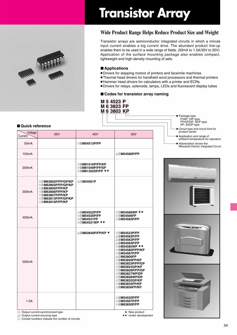
54
Transistor arrays are semiconductor integrated circuits in which a minuteinput current enables a big current drive. The abundant product line-upenables them to be used in a wide range of fields. (50mA to 1.5A/35V to 50V)Application of the surface mounting package also enables compact,lightweight and high-density mounting of sets.
� Applications� Drivers for stepping motors of printers and facsimile machines� Thermal head drivers for handheld word processors and thermal printers� Hammer head drivers for calculators with a printer and ECRs� Drivers for relays, solenoids, lamps, LEDs and fluorescent display tubes
Transistor Array
Package typeP/WP: DIP typeFP/GP/DP: SOP typeKP: SSOP type
Abbreviation shows theMitsubishi Electric Integrated Circuit
Application and range ofambient temperature for operation
Circuit type and circuit kind forproduct series
M 5 4523 PM 6 3823 FPM 6 3803 KP
� Codes for transistor array naming
Wide Product Range Helps Reduce Product Size and Weight
400mA
500mA
��M63802P/FP/GP/KP��M63803P/FP/GP/KP��M63805P/FP/KP��M63806P/FP/KP��M63807P/FP/KP��M63813P/FP/GP/KP��M63816P/FP/KP
1.5A� M54532P/FP� M54567P/FP� M63830P/FP
��M63840P/FP/KP � ��M54523P/FP��M54562P/FP��M54563P/FP��M54564P/FP��M54585WP ����M54585P/FP/KP��M54587P/FP��M63800FP��M63820FP/KP��M63823P/FP/GP��M63824GP/KP��M63826P/FP/GP��M63827WP/DP��M63828WP/DP��M63832GP/KP��M63834FP/KP��M63836FP/KP
��M54522P/FP��M54530P/FP��M54531FP��M54531WP ��
��M54566WP ����M54566FP��M54583P/FP
300mA
150mA
50mA ��M54513P/FP
��M54561P
��M54580P/FP
��M81016P/FP/KP��M81049P/FP/SP��M81302SP/FP ��
200mA
35V 40V 50VVoltageCurrent
�: Output current-synchronized type�: Output current-sourcing type� : Circled numbers indicate the number of circuits
�: New product��: Under development
� Quick reference
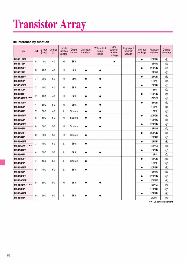
55
M54513FP
M54513P
M54522FP
M54522P
M54523FP
M54523P
M54530FP
M54530P
M54531FP
M54531WP ��
M54532FP
M54532P
M54561P
M54562FP
M54562P
M54563FP
M54563P
M54564FP
M54564P
M54566FP
M54566WP ��
M54567FP
M54567P
M54580FP
M54580P
M54583FP
M54583P
M54585FP
M54585KP
M54585WP ��
M54585P
M54587FP
M54587P
�
�
�
�
�
�
�
�
�
�
�
�
�
�
�
�
�
�
�
�
�
�
�
�
�
�
�
�
�
�
�
�
�
�
�
�
�
�
�
�
�
�
�
20P2N
18P4G
20P2N
18P4G
16P2N
16P4
16P2N
16P4
16P2N
16P4X
16P2N
16P4
16P4
20P2N
18P4G
20P2N
18P4G
20P2N
18P4G
16P2N
16P4X
16P2N
16P4
16P2N
16P4
20P2N
18P4G
20P2N
20P2E
18P4X
18P4G
20P2N
20P4
8
8
7
7
7
4
7
8
8
8
7
4
7
8
8
8
Sink
Sink
Sink
Sink
Sink
Sink
Source
Source
Source
Source
Sink
Sink
Source
Sink
Sink
Sink
H
H
H
H
H
H
L
H
H
H
L
L
L
L
H
L
40
40
50
40
40
50
40
50
50
50
50
50
50
50
50
50
50
400
500
400
400
1500
300
500
500
500
400
1500
150
400
500
500
�
�
�
�
�
�
�
�
�
�
�
�
�
�
�
�
�
�
�
�
�
�
�
�
�
�
�
�
�
�
�
�
Type Io max[mA]Unit Outline
drawingsVo max
[V]
Input-functionvoltage
Outputcurrent
Darlingtontransistor
With outputclamp-diode
Low collector-emitter voltage
High-inputthresholdvoltage
Mini-fratpackage
Packageoutlines
� Reference by function
��: Under development
Transistor Array

56
Type Io max[mA]Unit Outline
drawingsVo max
[V]
Input-functionvoltage
Outputcurrent
Darlingtontransistor
With outputclamp-diode
Low collector-emitter voltage
High-inputthresholdvoltage
Mini-fratpackage
Packageoutlines
� Reference by function
�: New product
M63800FP
M63802FP
M63802GP
M63802KP
M63802P
M63803FP
M63803GP
M63803KP
M63803P
M63805FP
M63805KP
M63805P
M63806FP
M63806KP
M63806P
M63807FP
M63807KP
M63807P
M63813FP
M63813GP
M63813KP
M63813P
M63816FP
M63816KP
M63816P
M63820FP
M63820KP
M63823FP
M63823GP
M63823P
M63824GP
M63824KP
M63826FP
M63826GP
M63826P
M63827WP
M63827DP
M63828WP
M63828DP
M63830FP
M63830P
M63832GP
M63832KP
M63834FP
M63834KP
M63836FP
M63836KP
M63840FP �
M63840KP �
M63840P �
16P2N
16P2N
16P2S
16P2Z
16P4
16P2N
16P2S
16P2Z
16P4
20P2N
20P2E
18P4G
20P2N
20P2E
18P4G
20P2N
20P2E
18P4G
16P2N
16P2S
16P2Z
16P4
20P2N
20P2E
18P4G
20P2N
20P2E
16P2N
16P2S
16P4
16P2S
16P2E
16P2N
16P2S
16P4
16P4X
16P2X
16P4X
16P2X
16P2N
16P4
16P2S
16P2E
20P2N
20P2E
20P2N
20P2E
20P2N
20P2F
18P4G
�
�
�
�
�
�
�
�
�
�
�
�
�
�
�
�
�
�
�
�
�
�
�
�
�
�
�
�
�
�
�
�
�
�
�
�
�
�
�
�
�
�
�
�
�
�
�
�
�
�
�
�
�
��
�
�
�
�
��
�
�
�
�
���
�
�
�
�
�
�
�
�
�
�
�
�
7
7
7
8
8
8
7
8
�
�
�
��
�
��
�
��
�
��
��
��
��
�
�
�
�
�
�
�
��
�
��
8
7
7
7
7
7
4
7
8
8
8
H
H
H
H
H
H
H
H
H
H
H
H
H
H
L
L
L
L
H
Source
Sink
Sink
Sink
Sink
Sink
Sink
Sink
Sink
Sink
Sink
Sink
Sink
Sink
Sink
Sink
Sink
Sink
Source
50
35
35
35
35
35
35
35
50
50
50
50
50
50
50
50
50
50
40
500
300
300
300
300
300
300
300
500
500
500
500
500
500
1500
500
500
500
500
�
�
�
�
�
�
�
�
�
Transistor Array

57
M81016P
M81016FP
M81016KP
M81049P
M81049FP8 Sink
OCTAL D-TYPE, FLIP-FLOP DRIVER WITH CLEAR
OCTAL INVERTER WITH OPEN-DREIN OUTPUTS
40200
�
�
�
�
20P4B �
20P2N �
20P2E �
20P4
20P2N �
M81049SP 20P4B �
M81302SP �� 20P4B �
M81302FP �� 20P2N �
� CMOS array
Type Io max[mA]Unit Outline
drawingsVo max
[V]Outputcurrent Function Mini-frat
packagePackageoutlines
��: Under development
Transistor Array

58
3
4
6
2
1
5
TYPE 20P2N 20pin 300mil SOP
TYPE 16P2N 16pin 300mil SOP
TYPE 14P4 14pin 300mil DIP
TYPE 16P4 16pin 300mil DIP
TYPE 18P4G 18pin 300mil DIP
TYPE 20P4 20pin 300mil DIP
24�0.2
7.62
0.5�0.12.54
6.3
�0.
150.
51 M
IN.
4.5
MAX
.3
MIN
.
3.3
19�0.2
7.62
0.5�0.12.54
6.3
�0.
150.
51 M
IN.
4.5
MAX
.3
MIN
.
3.3
19�0.2
7.62
0.5�0.12.54
6.3
�0.
150.
5 M
IN.
4.5
MAX
.3
MIN
.
3.3
24�0.2
7.62
0.5�0.12.54
6.3
�0.
150.
51 M
IN.
4.5
MA
X.
3 M
IN.
3.3
10.1�0.1
5.3
�0.
1 0.1�0.1
1.27
A
7.8
�0.
3
0.6
�0.
2
1.25
2.1 MAX.
1.8
Detail A
4��4�
12.6�0.1
1.27
5.3
�0.
11.
8
0.1�0.1
A
7.8
�0.
3
1.25
2.1MAX.
0.6
�0.
2
Detail A
4��4�
1.5+0.3–0.1
1.5+0.3–0.1
0.27+0.07–0.05
0.27+0.07–0.05
0.25+0.07–0.05
1.0+0.3–0.1
1.2+0.3–0.1
0.2+0.05–0.02
0.2+0.05–0.02
0.4+0.10–0.05
0.4+0.10–0.05
1.5+0.3–0.11.0
+0.3–0.1
0.27+0.07–0.05
� High-voltage integrated circuits and transistor array outline drawings (Unit: mm)

59
11
12
10
9 TYPE 20P2E-A 20pin 225mil SSOPTYPE 20P2F-A
TYPE 36P2R-D 36pin 450mil SSOP
TYPE 8P2S-A 8pin 225mil SOP
7
8
TYPE 16P2S 16pin 225mil SOP
TYPE 16P2Z 16pin 225mil SSOP
TYPE 10P2N-A 10pin 300mil SOP
1.45 MAX.
6.5�0.1
0.65
1.15
Detail A
0� to 10�
4.4�
0.1
6.4�
0.2
0.5�
0.2
1.0
A
0.1�0.1
8.4�
0.2
11.9
3�0.
3
0.85 MAX.
36
0.8
0.7
0.15 MAX.
2.35 MAX.G 15.0�0.2
2.05
0� to 8�
0.1�0.1
Detail G Detail F
1.76
5
0.5
�0.
2
F
19
1 18
5
4
8
1
6.2�
0.3
4.4�
0.2
0� to 10�
1.9 MAX.
0.1 MAX.0.25 MAX.
0.745 MAX.
0.05 MIN.
F
5.0�0.2
1.27
G
0.9
1.5
Detail F
0.4�
0.2
Detail G0.595
6.8�0.1
1.27
0.86
5.7�
0.1
8.12
�0.
3
1.21
F
2.1 MAX.
G
0.5�
0.2
Detail F
0�~ 8�
610
51
0.1 MAX.
1.01 MAX.
0.25 MAX.
Detail G
1.8 0.1�0.1
0.05 MIN.
A
6.2
�0.
3
0.9
1.9 MAX.
0.4
�0.
2
Detail A
0� to 10�
5�0.2
4.4
�0.
2
0.65
1.5
10�0.2
4.4
�0.
20.05 MIN.
1.27
A
6.2
�0.
3
0.4
�0.
2
0.9
1.9 MAX.
1.5
Detail A
0� to 10�0.4
+0.10–0.05
0.15+0.05–0.02
0.15+0.05–0.02
0.22+0.10–0.05
0.15+0.05–0.02
0.22+0.10–0.05
0.4+0.10–0.05
0.2+0.05–0.02
0.15+0.05–0.02
0.4+0.10–0.05
0.35+0.10–0.05
0.2+0.05–0.02
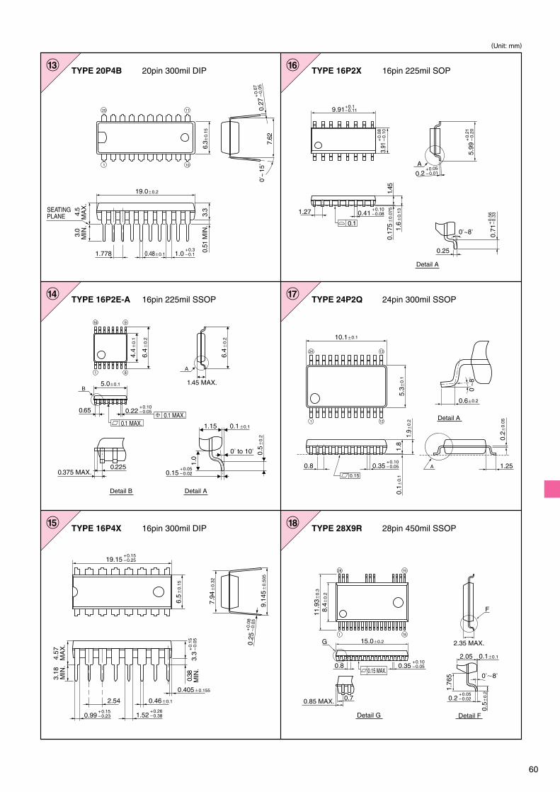
60
13
14
TYPE 20P4B 20pin 300mil DIP
15
TYPE 16P2E-A 16pin 225mil SSOP
16
TYPE 16P4X 16pin 300mil DIP
TYPE 24P2Q 24pin 300mil SSOP17
TYPE 16P2X 16pin 225mil SOP
18 TYPE 28X9R 28pin 450mil SSOP
A
Detail ADetail B
6.4
�0.
2
6.4
�0.
2
5.0�0.1
4.4
�0.
1
B
0.65
0.1 MAX.0.1 MAX.
1.45 MAX.
0.5
�0.
2
1.0
1.15 0.1�0.1
0� to 10�
0.375 MAX.0.225
81
916
7.94
�0.
32
9.14
5�
0.50
5
0.46�0.12.54
0.405�0.155
6.5
�0.
15
0.38
MIN
.
3.18
MIN
.4.
57 M
AX
.
0.17
5�
0.07
5
1.6
�0.
13
9.91
1.27
1.45
A
+0.1– 0.11
0.71
0.25
+0.
56– 0
.33
0�~8�
19.0�0.2
0.48�0.11.778
4.5
MA
X.
3.0
MIN
.
0.51
MIN
.3.
3
7.62
6.3�
0.15
0�~
15�
20 11
101
SEATINGPLANE
24 13
121
5.3�
0.1
A0.80.15
1.250�
~8�
1.9�
0.2
0.6�0.2
10.1�0.1
1.8
0.1�
0.1
0.2�
0.05
Detail A
0.15+0.05–0.02
Detail A
0.1
8.4�
0.2
11.9
3�0.
3
28
0.8
0.7
G 15.0�0.2
2.05
0��8�
0.1�0.1
Detail G Detail F
1.76
5
0.5�
0.2
F
19
1 18
0.15 MAX.
0.85 MAX.
2.35 MAX.
1.0+0.3–0.1
0.22+0.10–0.05
19.15+0.15–0.25
1.52+0.26–0.380.99
+0.15–0.23
3.3
+0.
15–
0.05 0.25
+0.
08–
0.05
0.35+0.10–0.05
0.2+0.05–0.02
0.35+0.10–0.05
0.41+0.10–0.08
3.91
+0.
08–
0.10
0.2+0.05–0.01
5.99
+0.
21–
0.20
0.27
+0.
07–
0.05
(Unit: mm)

61
19TYPE 18P4X 16pin 300mil DIP
2.54
6.5
�0.
150.
38M
IN.
3.18
MIN
.4.
57M
AX
.
9.01
5 �0.
635
7.96
�0.
32
0.46�0.1
22.96+0.16–0.25
1.52+0.26–0.25
0.56+0.14–0.13
3.3
+0.
26–
0.00 0.
25+
0.08
–0.
05
(Unit: mm)


