Download - STAND- ALONE-SYSTEMS - Eltek
STAND-ALONE-SYSTEMS

STAND-ALONE-SYSTEMS
Power Supply System SVS 48/60 V-120/100A SVS 48/60 V-360/300 A HPS 200 Wall 24/48 V-200 A
Type SVS-G48, 60/120-8GRS SVS-G48, 60/360-5GRS SVS-G48/200-1GRW
Rectifier RM 1800 RM 1800 HR 1300 / HR 1400
Rectifier type E60/25 WBrug-2GRM E60/25 WBrug-2GRM E48/25 WBrug-1GRM
Max. rectifier number 4 12 8 (2 x HPU 5200)
Control and monitoring unit SVS-SM7 SVS-SM7 HPU-SM2
Input 1ph or 3ph with N 1ph or 3ph with N 1ph or 3ph with N
Voltage 230 V / 400 V 230 V / 400 V 3 x 120 V / 208 V, 3 x 230 V / 400 V
Max. current per phase 22 A 3 44 A 3 24 A 3
Frequency 45–65 Hz 45–65 Hz 45–65 Hz
Power factor cos φ ≈ 1, EN 61000-3-2 cos φ ≈ 1, EN 61000-3-2 cos φ ≈ 1, EN 61000-3-2
Output
Voltage selectable 24 V / 48 V / 60 V 1 24 V / 48 V / 60 V 1 24 V / 48 V / 60 V 1
Max. current 120 A 360 A 200 A
Psophometric noise < 2 mV, ETSI 300 132-2/ITU-T < 2 mV, ETSI 300 132-2/ITU-T < 2 mV, ETSI 300 132-2/ITU-T
General data
Load feeders 5 x circuit breaker 3 x 16 A 2 x 50 A
17 x NH0031 x circuit breaker
14 x circuit breaker (expandable)
Protection class IP20, EN 60529 IP20, EN 60529 IP20, EN 60529
Ambient temperature –10 to +45 °C 2 –10 to +45 °C 2 –20 to +60 °C with derating > 50 °C
Weight
Without modules 43 kg 170 kg 48 kg
Fully equipped 66 kg 240 kg 70 kg
DimensionsH x W x D (in mm)
650 x 600 x 500 2000 x 600 x 500 670 x 600 x 400
Options
SNMP-adapter yes yes yes
Modem-signalling yes yes yes
Deep voltage discharge protection
yes yes yes
Temperature compensation yes yes yes
Battery Cabinets(H x W x D in mm)
650 x 600 x 5001000 x 600 x 5001400 x 600 x 500
on request on request
1 24 V with suitable LVD
2 –33 to +55 °C possible
3 if 3 ph
Right to make technical changes reserved

STAND-ALONE-SYSTEMS
Power Supply System HPS 400 Floor 24/48 V-400 A HPS 760 with BVS 800 SVS 48/60 V-1250 A
Type SVS-G48/400-1GRF G48,60/760-1GRS01 / BV48,60/800-1BVS01
according implementation
Rectifier HR 1300 / HR 1400 HR 1300 / HR 1400 RM 18000
Rectifier type E48/25 WBrug-1GRM E48/25 WBrug-1GRM / E60/21 WBrug-1GRM01
D60/250 WBrug-1GRM
Max. rectifier number 16 (4x HPU 5200) 32 (8 x HPU 5200) 5
Control and monitoring unit HPU-SM2 HPU-SM2 HPU-SM3
Input 1ph or 3ph with N 1ph or 3ph with N 3 ph without N
Voltage 3 x 120 V / 208 V, 3 x 230 V / 400 V
3 x 120 V / 208 V, 3 x 230 V / 400 V
400 V
Max. current per phase 32 A 3 88 A 3 140 A
Frequency 45–66 Hz 45–66 Hz 45–65 Hz
Power factor cos φ ≈ 1, EN 61000-3-2 cos φ ≈ 1, EN 61000-3-2 λ > 0,94
Output
Voltage selectable 24 V / 48 V / 60 V 24 V / 48 V (HR1300) 48 V / 60 V (HR1400) 24 V / 48 V / 60 V 1
Max. current 400 A 800 A 1250 A
Psophometric noise < 2 mV, ETSI 300 132-2/ITU-T < 2mV, ETSI 300 132-2/ITU-T < 2 mV, ETSI 300 132-2/ITU-T
General data
Load feeders 14 x circuit breaker (expandable) 18 x NH00 TPS (400A) closedor -27 x NH00 closedor -18 x NH1-3 openor -39 x NH00 open
10 x NH3 closedor -22 x NH00 closedor - 22 x NH1-3 open or - 32 x NH00 open
Protection class IP20, EN 60529 IP20, EN 60529 IP20, EN 60529
Ambient temperature –20 bis +60 °C with derating > 50 °C –20 to +60 °C with derating > 50 °C –10 to +45 °C
Weight
Without modules 76 kg 95 kg (HPS760) 122 kg (BVS800) 302 kg
Fully equipped 118 kg 230 kg (HPS760) 180 kg BVS800) 519 kg
DimensionsH x W x D (in mm)
1800 x 600 x 600 1800 x 600 x 600 (HPS760)1800 x 600 x 600 (BVS800)
2000 x 1400 x 600
Options
SNMP-adapter yes yes yes
Modem-signalling yes yes yes
Deep voltage discharge protection
yes yes yes
Temperature compensation yes yes yes
Battery Cabinets(H x W x D in mm)
integrated battery compartment, max. 3 levels per 100 Ah
on request on request
1 24 V with suitable LVD
2 –33 to +55 °C possible
3 if 3 ph
Right to make technical changes reserved

STAND-ALONE-SYSTEMS
Power Supply System SVS 48/60 V-2500 A FP2 Systems 600A Outdoorsystems customized
Type according implementation FP2 Sytem 400Vac 48V 600A SVS-G48/300-1OUT
Rectifier RM 18000 FP2 48V 2000W HR 1300/ HR 1400
Rectifier type D60/250 WBrug-1GRM E48/41 WBrug-1GRM E48/25 WBrug-1GRM
Max. rectifier number 10 16 (expandable on request) 12 (3 x HPU 5200)
Control and monitoring unit HPU-SM3 Smartpack HPU-SM2
Input 3 ph without N 1ph or 3ph with N 1ph or 3ph with N
Voltage 400 V 400 V 3 x 230 V / 400 V
Max. current per phase 280 A 60 A 3 32 A 3
Frequency 45–65 Hz 45–65 Hz 45–66 Hz
Power factor λ > 0,94 cos φ ≈ 1, EN 61000-3-2 cos φ ≈ 1, EN 61000-3-2
Output
Voltage selectable 24 V / 48 V / 60 V 1 48 V 24 V / 48 V / 60 V 1
Max. current 2500 A 600 A 300 A
Psophometric noise < 2 mV, ETSI 300 132-2/ITU-T < 1 mV, ETSI 300 132-2/ITU-T < 2 mV, ETSI 300 132-2/ITU-T
General data
Load feeders 8 x NH3 closedor -19 x NH00 closedor - 19 x NH1-3 open or - 28 x NH00 open
up to 46 x circuit breaker 1 to 125 A
10 x circuit breaker (expandable)
Protection class IP20, EN 60529 IP20, EN 60529 IP54, EN 60529
Ambient temperature –10 to +45 °C 2 –40 to +70 °C (with derating > 50 °C) –33 to +45 °C
Weight
Without modules 454 kg 100 227 kg
Fully equipped 889 kg 130 258 kg
DimensionsH x W x D (in mm)
2000 x 2100 x 600 (without mains distribution cabinet)
2000 x 600 x 600 1940 x 770 x 805
Options
SNMP-adapter yes yes yes
Modem-signalling yes yes yes
Deep voltage discharge protection
yes yes yes
Temperature compensation yes yes yes
Battery Cabinets(H x W x D in mm)
– 4 x 150 A / 48 V integrable integrated battery compartment, max. 2 levels per 100 Ah
1 24 V with suitable LVD
2 –33 to +55 °C possible
3 if 3 ph
Right to make technical changes reserved
STAND-ALONE-SYSTEMS
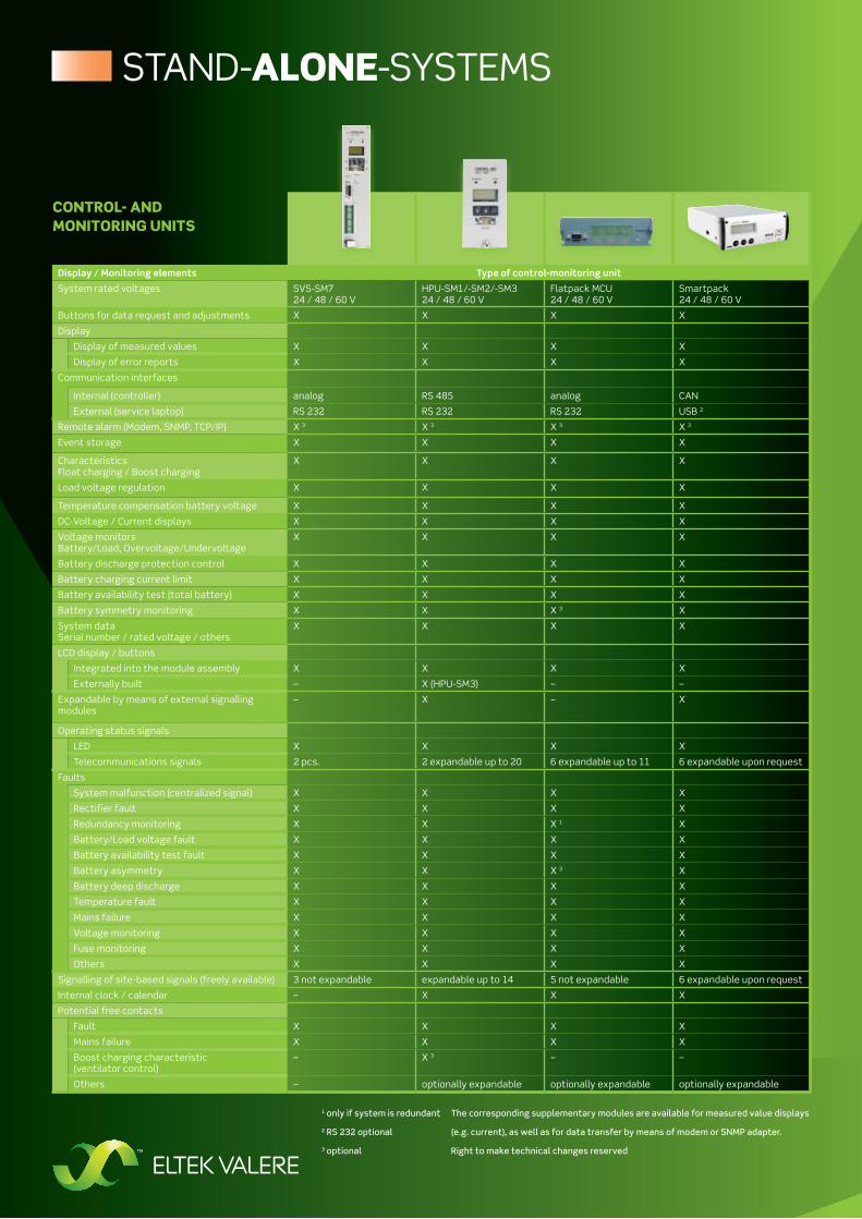
Display / Monitoring elements Type of control-monitoring unit
System rated voltages SVS-SM724 / 48 / 60 V
HPU-SM1/-SM2/-SM324 / 48 / 60 V
Flatpack MCU24 / 48 / 60 V
Smartpack 24 / 48 / 60 V
Buttons for data request and adjustments X X X X
Display
Display of measured values X X X X
Display of error reports X X X X
Communication interfaces
Internal (controller) analog RS 485 analog CAN
External (service laptop) RS 232 RS 232 RS 232 USB 2
Remote alarm (Modem, SNMP, TCP/IP) X 3 X 3 X 3 X 3
Event storage X X X X
Characteristics Float charging / Boost charging
X X X X
Load voltage regulation X X X X
Temperature compensation battery voltage X X X X
DC-Voltage / Current displays X X X X
Voltage monitors Battery/Load, Overvoltage/Undervoltage
X X X X
Battery discharge protection control X X X X
Battery charging current limit X X X X
Battery availability test (total battery) X X X X
Battery symmetry monitoring X X X 3 X
System dataSerial number / rated voltage / others
X X X X
LCD display / buttons
Integrated into the module assembly X X X X
Externally built – X (HPU-SM3) – –
Expandable by means of external signalling modules
– X – X
Operating status signals
LED X X X X
Telecommunications signals 2 pcs. 2 expandable up to 20 6 expandable up to 11 6 expandable upon request
Faults
System malfunction (centralized signal) X X X X
Rectifier fault X X X X
Redundancy monitoring X X X 1 X
Battery/Load voltage fault X X X X
Battery availability test fault X X X X
Battery asymmetry X X X 3 X
Battery deep discharge X X X X
Temperature fault X X X X
Mains failure X X X X
Voltage monitoring X X X X
Fuse monitoring X X X X
Others X X X X
Signalling of site-based signals (freely available) 3 not expandable expandable up to 14 5 not expandable 6 expandable upon request
Internal clock / calendar – X X X
Potential free contacts
Fault X X X X
Mains failure X X X X
Boost charging characteristic (ventilator control)
– X 3 – –
Others – optionally expandable optionally expandable optionally expandable
The corresponding supplementary modules are available for measured value displays
(e.g. current), as well as for data transfer by means of modem or SNMP adapter.
Right to make technical changes reserved
1 only if system is redundant
2 RS 232 optional
3 optional
CONtrOL- ANd mONitOriNg uNits

ELTEK VALERE DEuTschLAnD Gmbh
Ferdinand-Porsche-Straße 4560386 Frankfurt am MainGermany
P.O. Box 61 06 5160348 Frankfurt am MainGermany
Phone: +49 (69) 420 02 0Telefax: +49 (69) 420 02 389
www.eltekvalere.deemail: [email protected]


