Download - Shaft Mounted Clutches & Brakes - Literature
A L T R A I N D U S T R I A L M O T I O N
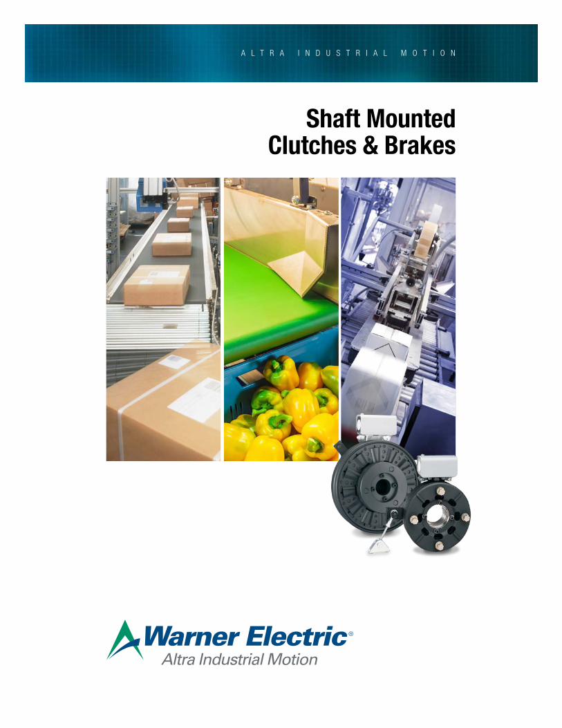
Shaft Mounted Clutches & Brakes
Altra is a leading global designer and producer of a wide range of electromechanical power transmission and motion control components and systems. Providing the essential control of equipment speed, torque, positioning, and other functions, Altra products can be used in nearly any machine, process or application involving motion. From engine braking systems for heavy duty trucks to precision motors embedded in medical robots to brakes used on offshore wind turbines, Altra has been serving customers around the world for decades.
Altra’s leading brands include Ameridrives, Bauer Gear Motor, Bibby Turboflex, Boston Gear, Delevan, Delroyd Worm Gear, Deltran, Formsprag Clutch, Guardian Couplings, Huco, Jacobs Vehicle Systems, Kilian, Kollmorgen, Lamiflex Couplings, Marland Clutch, Matrix, Nuttall Gear, Portescap, Stieber, Stromag, Svendborg Brakes, TB Wood’s, Thomson, Twiflex, Warner Electric, Warner Linear and Wichita Clutch.
VISIT US ON THE WEB AT ALTRAMOTION.COM
Altra Motion
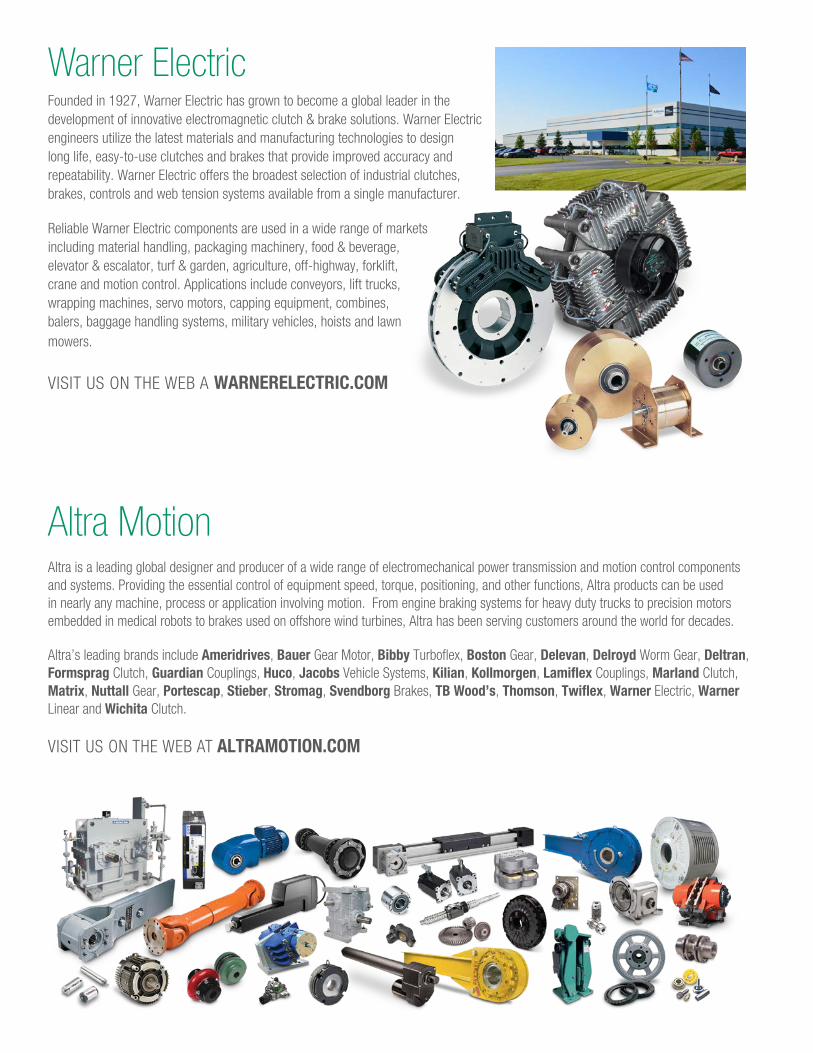
Warner ElectricFounded in 1927, Warner Electric has grown to become a global leader in the development of innovative electromagnetic clutch & brake solutions. Warner Electric engineers utilize the latest materials and manufacturing technologies to design long life, easy-to-use clutches and brakes that provide improved accuracy and repeatability. Warner Electric offers the broadest selection of industrial clutches, brakes, controls and web tension systems available from a single manufacturer.
Reliable Warner Electric components are used in a wide range of markets including material handling, packaging machinery, food & beverage, elevator & escalator, turf & garden, agriculture, off-highway, forklift, crane and motion control. Applications include conveyors, lift trucks, wrapping machines, servo motors, capping equipment, combines, balers, baggage handling systems, military vehicles, hoists and lawn mowers.
VISIT US ON THE WEB A WARNERELECTRIC.COM
TOC1www.warnerelectric.comP-8587-WE 3/19
Pages Shaft Mounted Clutches & Brakes
1-6 Product Line Overview Introduction to Packaged Performance Products
A-2 Electro Clutches (EC Series)
A-9 Electro Brakes (EB Series)
A-15 Advanced Technology Clutches (ATC Series)
A-23 Advanced Technology Brakes (ATB Series)
A-25 Packaged Stationary Field Clutches (SFP Series)
SP-1 Shaft Mounted Compatible Service Parts
G-1
G-3
G-4
G-8
General Engineering Data
NEMA Standard Ordering Info
Mechanical
Electrical Data
AD-1 Application Data Form
B-1 Bushing Part Numbers
CTL-1 Clutch/Brake Controls
PN-1 Part Number Ordering Information
I-1 Index
Shaft Mounted Clutches & Brakes
Need to update for P-8587-WE
1 www.warnerelectric.com Introduction to Packaged Performance Products 3/19
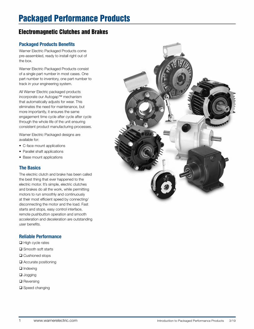
Packaged Products BenefitsWarner Electric Packaged Products come pre-assembled, ready to install right out of the box.
Warner Electric Packaged Products consist of a single part number in most cases. One part number to inventory, one part number to track in your engineering system.
All Warner Electric packaged products incorporate our Autogap™ mechanism that automatically adjusts for wear. This eliminates the need for maintenance, but more importantly, it ensures the same engagement time cycle after cycle after cycle through the whole life of the unit ensuring consistent product manufacturing processes.
Warner Electric Packaged designs are available for:
• C-face mount applications
• Parallel shaft applications
• Base mount applications
The BasicsThe electric clutch and brake has been called the best thing that ever happened to the electric motor. It’s simple, electric clutches and brakes do all the work, while permitting motors to run smoothly and continuously at their most efficient speed by connecting/disconnecting the motor and the load. Fast starts and stops, easy control interface, remote pushbutton operation and smooth acceleration and deceleration are outstanding user benefits.
Reliable Performanceq High cycle rates
q Smooth soft starts
q Cushioned stops
q Accurate positioning
q Indexing
q Jogging
q Reversing
q Speed changing
Packaged Performance ProductsElectromagnetic Clutches and Brakes
2Introduction to Packaged Performance Products 3/19 www.warnerelectric.com
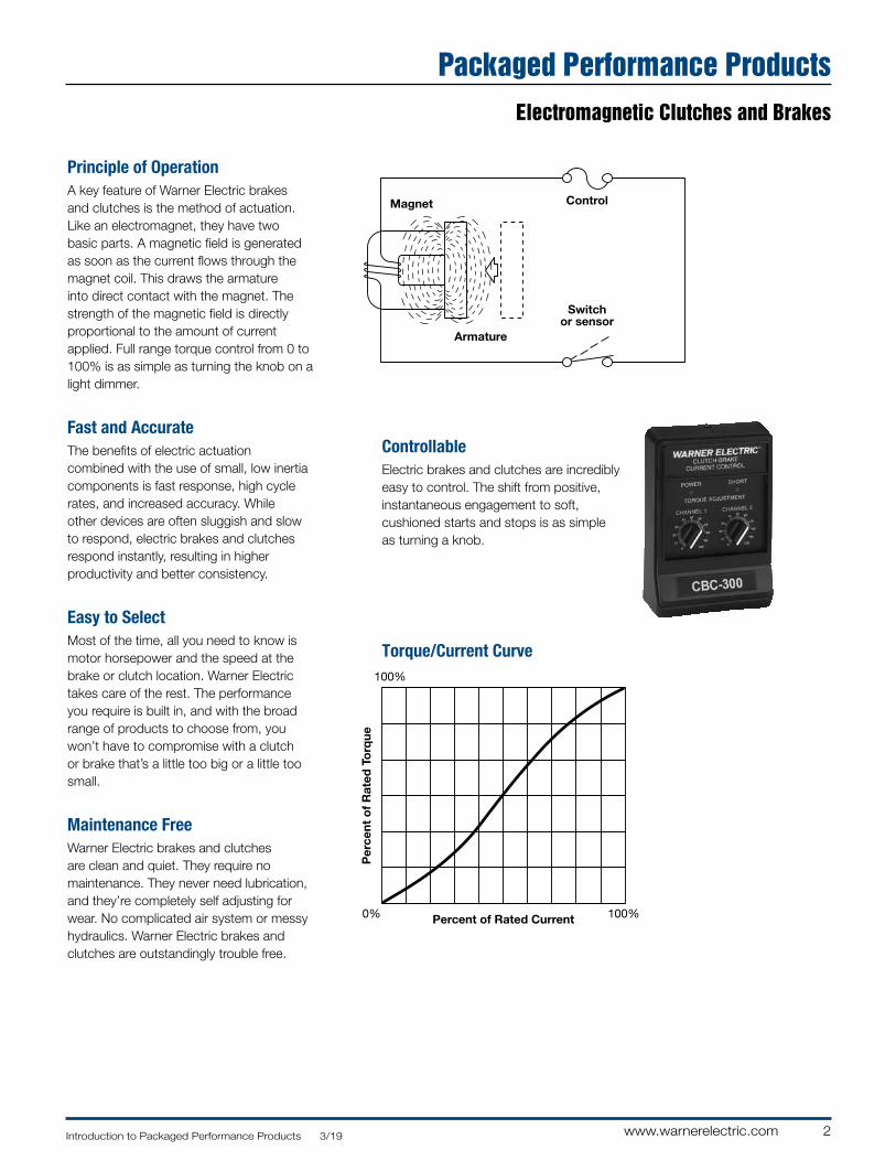
ControllableElectric brakes and clutches are incredibly easy to control. The shift from positive, instantaneous engagement to soft, cushioned starts and stops is as simple as turning a knob.
Control
Switchor sensor
Armature
Magnet
Principle of Operation3/3/00
Voltage/Torque Curve3/3/00
Percent of Rated Current
Per
cent
of
Rat
ed T
orq
ue
0% 100%
100%
Principle of OperationA key feature of Warner Electric brakes and clutches is the method of actuation. Like an electromagnet, they have two basic parts. A magnetic field is generated as soon as the current flows through the magnet coil. This draws the armature into direct contact with the magnet. The strength of the magnetic field is directly proportional to the amount of current applied. Full range torque control from 0 to 100% is as simple as turning the knob on a light dimmer.
Fast and AccurateThe benefits of electric actuation combined with the use of small, low inertia components is fast response, high cycle rates, and increased accuracy. While other devices are often sluggish and slow to respond, electric brakes and clutches respond instantly, resulting in higher productivity and better consistency.
Easy to SelectMost of the time, all you need to know is motor horsepower and the speed at the brake or clutch location. Warner Electric takes care of the rest. The performance you require is built in, and with the broad range of products to choose from, you won’t have to compromise with a clutch or brake that’s a little too big or a little too small.
Maintenance FreeWarner Electric brakes and clutches are clean and quiet. They require no maintenance. They never need lubrication, and they’re completely self adjusting for wear. No complicated air system or messy hydraulics. Warner Electric brakes and clutches are outstandingly trouble free.
Torque/Current Curve
Packaged Performance ProductsElectromagnetic Clutches and Brakes
3 www.warnerelectric.com Introduction to Packaged Performance Products 3/19
Packaged Performance Products
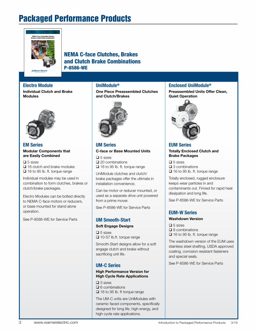
Electro ModuleIndividual Clutch and Brake Modules
UniModule®
One Piece Preassembled Clutches and Clutch/Brakes
Enclosed UniModule®
Preassembled Units Offer Clean, Quiet Operation
EM Series Modular Components that are Easily Combined
q 5 sizesq 16 clutch and brake modulesq 16 to 95 lb. ft. torque range
Individual modules may be used in combination to form clutches, brakes or clutch/brake packages.
Electro Modules can be bolted directly to NEMA C-face motors or reducers, or base mounted for stand alone operation.
See P-8586-WE for Service Parts
UM Series C-face or Base Mounted Units
q 5 sizesq 20 combinationsq 16 to 95 lb. ft. torque range
UniModule clutches and clutch/brake packages offer the ultimate in installation convenience.
Can be motor or reducer mounted, or used as a separate drive unit powered from a prime mover.
See P-8586-WE for Service Parts
UM Smooth-Start Soft Engage Designs
q 5 sizesq 10-57 lb.ft. torque range
Smooth-Start designs allow for a soft engage clutch and brake without sacrificing unit life.
UM-C Series High Performance Version for High Cycle Rate Applications
q 3 sizesq 6 combinationsq 16 to 95 lb. ft torque range
The UM-C units are UniModules with ceramic faced components, specifically designed for long life, high energy, and high cycle rate applications.
EUM Series Totally Enclosed Clutch and Brake Packages
q 5 sizesq 3 combinationsq 16 to 95 lb. ft. torque range
Totally enclosed, rugged enclosure keeps wear particles in and contaminants out. Finned for rapid heat dissipation and long life.
See P-8586-WE for Service Parts
EUM-W Series Washdown Version
q 5 sizesq 8 combinationsq 16 to 95 lb. ft. torque range
The washdown version of the EUM uses stainless steel shafting, USDA approved coating, corrosion resistant fasteners and special seals.
See P-8586-WE for Service Parts
NEMA C-face Clutches, Brakes and Clutch Brake Combinations P-8586-WE
A L T R A I N D U S T R I A L M O T I O N
NEMA C-Face Compatible Clutches, Brakes & Clutch Brake Combinations
WARNER ELECTRIC
NEMA C-Face Clutches &
Brakes
4Introduction to Packaged Performance Products 3/19 www.warnerelectric.com
Packaged Performance Products
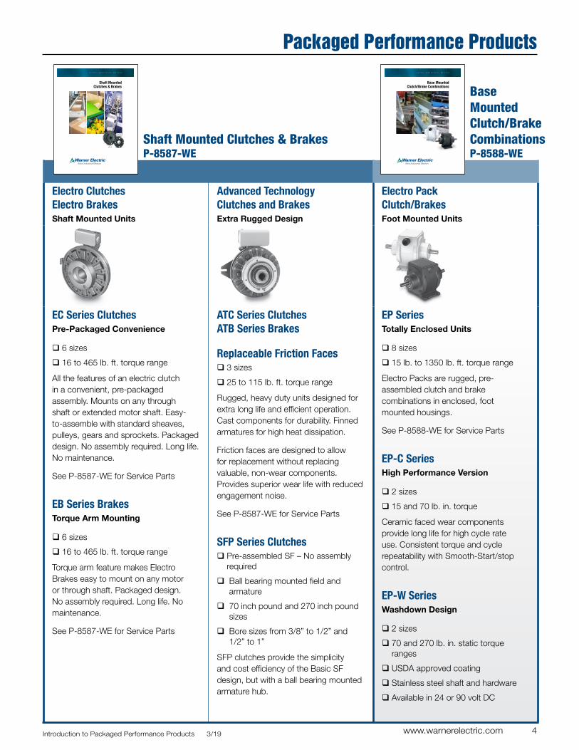
Electro Clutches Electro BrakesShaft Mounted Units
Advanced Technology Clutches and BrakesExtra Rugged Design
Electro Pack Clutch/BrakesFoot Mounted Units
EC Series ClutchesPre-Packaged Convenience
q 6 sizes
q 16 to 465 lb. ft. torque range
All the features of an electric clutch in a convenient, pre-packaged assembly. Mounts on any through shaft or extended motor shaft. Easy-to-assemble with standard sheaves, pulleys, gears and sprockets. Packaged design. No assembly required. Long life. No maintenance.
See P-8587-WE for Service Parts
EB Series BrakesTorque Arm Mounting
q 6 sizes
q 16 to 465 lb. ft. torque range
Torque arm feature makes Electro Brakes easy to mount on any motor or through shaft. Packaged design. No assembly required. Long life. No maintenance.
See P-8587-WE for Service Parts
ATC Series Clutches ATB Series Brakes
Replaceable Friction Faces q 3 sizes
q 25 to 115 lb. ft. torque range
Rugged, heavy duty units designed for extra long life and efficient operation. Cast components for durability. Finned armatures for high heat dissipation.
Friction faces are designed to allow for replacement without replacing valuable, non-wear components. Provides superior wear life with reduced engagement noise.
See P-8587-WE for Service Parts
SFP Series Clutchesq Pre-assembled SF – No assembly
required
q Ball bearing mounted field and armature
q 70 inch pound and 270 inch pound sizes
q Bore sizes from 3/8” to 1/2” and 1/2” to 1”
SFP clutches provide the simplicity and cost efficiency of the Basic SF design, but with a ball bearing mounted armature hub.
EP SeriesTotally Enclosed Units
q 8 sizes
q 15 lb. to 1350 lb. ft. torque range
Electro Packs are rugged, pre-assembled clutch and brake combinations in enclosed, foot mounted housings.
See P-8588-WE for Service Parts
EP-C SeriesHigh Performance Version
q 2 sizes
q 15 and 70 lb. in. torque
Ceramic faced wear components provide long life for high cycle rate use. Consistent torque and cycle repeatability with Smooth-Start/stop control.
EP-W SeriesWashdown Design
q 2 sizes
q 70 and 270 lb. in. static torque ranges
q USDA approved coating
q Stainless steel shaft and hardware
q Available in 24 or 90 volt DC
Shaft Mounted Clutches & Brakes P-8587-WE
Base Mounted Clutch/Brake Combinations P-8588-WE
A L T R A I N D U S T R I A L M O T I O N
Shaft Mounted Clutches & Brakes
A L T R A I N D U S T R I A L M O T I O N
Base Mounted Clutch/Brake Combinations

5 www.warnerelectric.com Introduction to Packaged Performance Products 3/19
Spring-Set BrakesFor Power-Off Static Holding and Emergency Stopping Applications
WARNING For general use in horizontal shaft applications only. For possible vertical applications, contact technical support.
Permanent Magnet BrakesFor Power-Off Dynamic Stopping and Cycling Applications
ERS SeriesStatic Engaged
q 5 sizes
q 1.5 to 100 lb. ft. holding torque
Designed for static holding. ERS models feature multiple coil springs that force armature and friction faces together to generate braking torque when power is off. The Electromagnet counters the spring force to disengage the brake when power is applied.
Although this brake should be engaged only when the shaft is a rest, it can occasionally act as a dynamic braking device to stop a rotating load in an emergency situation.
Spring Set Brake Module q 7 to 100 lb. ft. holding torque
NEMA C-face version of the ERS Series
ERD SeriesDynamic Braking
q 8 sizes
q 4 to 221 lb. ft. holding torque
ERD units are electrically released, static and dynamic engaged, spring-set brakes for power-off load holding applications. These spring-set brakes automatically stop and hold a load in the event of a power failure or other emergency stop situations. Fully dynamic friction material allows for repeated braking cycles from full motor speed with no torque fade. An optional manual release allows the brake to be released by hand.
Unibrake Series AC Motor Brakes
q Spring Set/Solenoid Released
q Direct acting/manual release standard 3 families
q 3, 6, 10 and 15 lb. ft. capacity
q Steel or cast iron covers
q Rear mount or double C-face designs
FB SeriesShaft Mounted, Dynamic Braking
q 3 models
q 10.5 to 56 lb. ft. static torque
Permanent magnet brakes are designed to dynamically stop and hold a moving load and also for high cycle rate stopping. Electric power to the coil nullifies the attraction of the permanent magnet, releasing the brake.
FB models are pre-assembled and feature a torque arm for convenient shaft mounting.
See P-8590-WE for Service Parts.
ER Series Flange Mounted, Dynamic Braking
q 5 models
q 10.5 to 400 lb. ft. static torque
The ER style brake offers a bulk head flange mounting system, the highest torque rating offered by Warner Electric in the power released series, high cycle rate capability, and excellent life. They require some assembly.
See P-8590-WE for Service Parts.
Packaged Performance Products
Electrically Released Spring-Set Brakes & Unibrake AC Motor Brakes P-8589-WE
A L T R A I N D U S T R I A L M O T I O N
Electrically Released Spring-Set Brakes & Unibrake AC Motor Brakes
6Introduction to Packaged Performance Products 3/19 www.warnerelectric.com
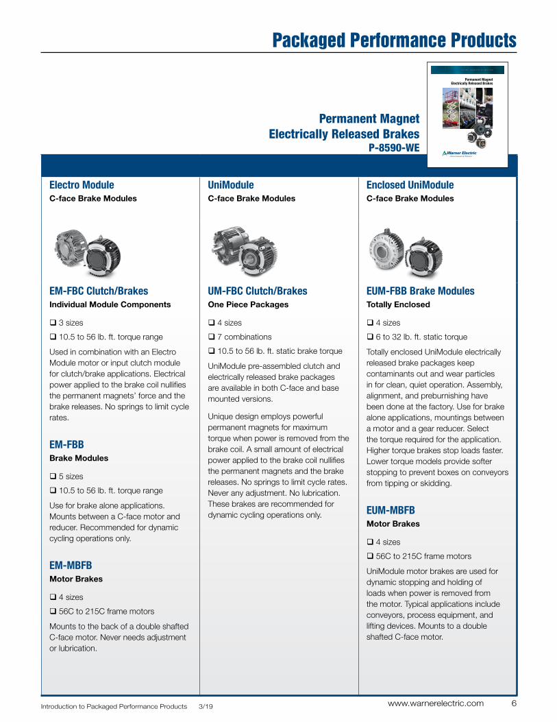
Electro ModuleC-face Brake Modules
UniModuleC-face Brake Modules
Enclosed UniModuleC-face Brake Modules
EM-FBC Clutch/BrakesIndividual Module Components
q 3 sizes
q 10.5 to 56 lb. ft. torque range
Used in combination with an Electro Module motor or input clutch module for clutch/brake applications. Electrical power applied to the brake coil nullifies the permanent magnets’ force and the brake releases. No springs to limit cycle rates.
EM-FBB Brake Modules
q 5 sizes
q 10.5 to 56 lb. ft. torque range
Use for brake alone applications. Mounts between a C-face motor and reducer. Recommended for dynamic cycling operations only.
EM-MBFBMotor Brakes
q 4 sizes
q 56C to 215C frame motors
Mounts to the back of a double shafted C-face motor. Never needs adjustment or lubrication.
UM-FBC Clutch/BrakesOne Piece Packages
q 4 sizes
q 7 combinations
q 10.5 to 56 lb. ft. static brake torque
UniModule pre-assembled clutch and electrically released brake packages are available in both C-face and base mounted versions.
Unique design employs powerful permanent magnets for maximum torque when power is removed from the brake coil. A small amount of electrical power applied to the brake coil nullifies the permanent magnets and the brake releases. No springs to limit cycle rates. Never any adjustment. No lubrication. These brakes are recommended for dynamic cycling operations only.
EUM-FBB Brake ModulesTotally Enclosed
q 4 sizes
q 6 to 32 lb. ft. static torque
Totally enclosed UniModule electrically released brake packages keep contaminants out and wear particles in for clean, quiet operation. Assembly, alignment, and preburnishing have been done at the factory. Use for brake alone applications, mountings between a motor and a gear reducer. Select the torque required for the application. Higher torque brakes stop loads faster. Lower torque models provide softer stopping to prevent boxes on conveyors from tipping or skidding.
EUM-MBFB Motor Brakes
q 4 sizes
q 56C to 215C frame motors
UniModule motor brakes are used for dynamic stopping and holding of loads when power is removed from the motor. Typical applications include conveyors, process equipment, and lifting devices. Mounts to a double shafted C-face motor.
Packaged Performance Products
Permanent Magnet Electrically Released Brakes
P-8590-WE
A L T R A I N D U S T R I A L M O T I O N
Permanent Magnet Electrically Released Brakes
7 www.warnerelectric.com Introduction to Packaged Performance Products 3/19
Notes
A-1www.warnerelectric.comP-8587-WE 3/19
A
Electro Clutches and Brakes
Advanced Technology Clutches and Brakes
Packaged Stationary Field Clutches
A-2 www.warnerelectric.com P-8587-WE 3/19
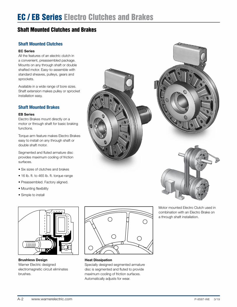
Shaft Mounted Clutches and Brakes
EC / EB Series Electro Clutches and Brakes
Shaft Mounted ClutchesEC SeriesAll the features of an electric clutch in a convenient, preassembled package. Mounts on any through shaft or double shafted motor. Easy-to-assemble with standard sheaves, pulleys, gears and sprockets.
Available in a wide range of bore sizes. Shaft extension makes pulley or sprocket installation easy.
Shaft Mounted BrakesEB SeriesElectro Brakes mount directly on a motor or through shaft for basic braking functions.
Torque arm feature makes Electro Brakes easy to install on any through shaft or double shaft motor.
Segmented and fluted armature disc provides maximum cooling of friction surfaces.
• Six sizes of clutches and brakes
• 16 lb. ft. to 465 lb. ft. torque range
• Preassembled. Factory aligned.
• Mounting flexibility
• Simple to install
Brushless DesignWarner Electric designed electromagnetic circuit eliminates brushes.
Heat DissipationSpecially designed segmented armature disc is segmented and fluted to provide maximum cooling of friction surfaces. Automatically adjusts for wear.
Electro Clutch/Segmented11/5/99page 74
Electro Clutch/Brushless11/5/99page 74
Motor mounted Electro Clutch used in combination with an Electro Brake on a through shaft installation.
A-3www.warnerelectric.comP-8587-WE 3/19
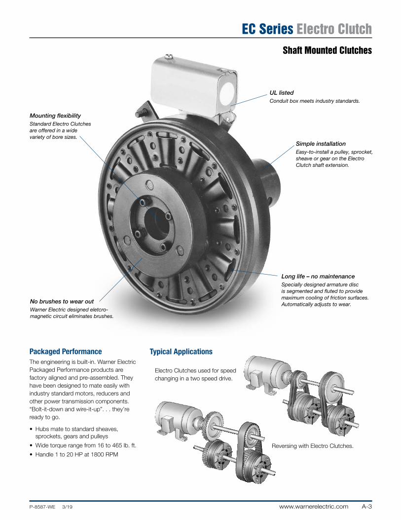
EC Series Electro Clutch
Mounting flexibilityStandard Electro Clutches are offered in a wide variety of bore sizes.
Packaged PerformanceThe engineering is built-in. Warner Electric Packaged Performance products are factory aligned and pre-assembled. They have been designed to mate easily with industry standard motors, reducers and other power transmission components. “Bolt-it-down and wire-it-up”. . . they’re ready to go.
• Hubs mate to standard sheaves, sprockets, gears and pulleys
• Wide torque range from 16 to 465 lb. ft.
• Handle 1 to 20 HP at 1800 RPM
Simple installationEasy-to-install a pulley, sprocket, sheave or gear on the Electro Clutch shaft extension.
UL listedConduit box meets industry standards.
Typical Applications
Long life – no maintenanceSpecially designed armature disc is segmented and fluted to provide maximum cooling of friction surfaces. Automatically adjusts to wear.
Reversing with Electro Clutches.
Electro Clutches used for speed changing in a two speed drive.
No brushes to wear outWarner Electric designed eletcro- magnetic circuit eliminates brushes.
Shaft Mounted Clutches
A-4 www.warnerelectric.com P-8587-WE 3/19
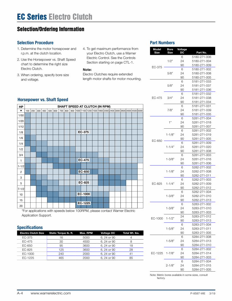
Selection/Ordering Information
EC Series Electro Clutch
Selection Procedure1. Determine the motor horsepower and
r.p.m. at the clutch location.
2. Use the Horsepower vs. Shaft Speed chart to determine the right size Electro Clutch.
3. When ordering, specify bore size and voltage.
4. To get maximum performance from your Electro Clutch, use a Warner Electric Control. See the Controls Section starting on page CTL-1.
Note:Electro Clutches require extended length motor shafts for motor mounting.
EC HP/Shaft Speed Chart11/14/99page 76
100
1/50
1/20
1/12
1/8
1/6
1/4
1/2
3/4
1
1-1/2
2
3
5
7-1/2
10
15
20
HP
Horsepower vs. Shaft Speed
SHAFT SPEED AT CLUTCH (IN RPM)1000
EC-375
EC-475
EC-650
EC-825
EC-1000
EC-1225
200 300 400 500 600 700 800 900 1100 1200 1500 1800 2000 2400 3000 3600 4000 4500 5000
Horsepower vs. Shaft Speed
SpecificationsElectro Clutch Size Static Torque lb. ft. Max. RPM Voltage DC Total Wt. lbs.
EC-375 16 5000 6, 24 or 90 4EC-475 30 4500 6, 24 or 90 8EC-650 95 3600 6, 24 or 90 18EC-825 125 3600 6, 24 or 90 28EC-1000 240 2000 6, 24 or 90 41EC-1225 465 2000 6, 24 or 90 85
Part NumbersModel Size
Bore Size
Voltage DC Part No.
EC-375
6 5180-271-0061/2” 24 5180-271-004
90 5180-271-0096 5180-271-002
5/8” 24 5180-271-00890 5180-271-005
EC-475
6 5181-271-0335/8” 24 5181-271-037
90 5181-271-0366 5181-271-032
3/4” 24 5181-271-03890 5181-271-0346 5181-271-031
7/8” 24 5181-271-03990 5181-271-035
EC-650
6 5281-271-0041” 24 5281-271-018
90 5281-271-0076 5281-271-002
1-1/8” 24 5281-271-01990 5281-271-0056 5281-271-009
1-1/4” 24 5281-271-02090 5281-271-0086 5281-271-003
1-3/8” 24 5281-271-01690 5281-271-006
EC-825
6 5282-271-0021-1/8” 24 5282-271-008
90 5282-271-0116 5282-271-003
1-1/4” 24 5282-271-00990 5282-271-0126 5282-271-004
1-3/8” 24 5282-271-01090 5282-271-013
EC-1000
6 5283-271-0021-3/8” 24 5283-271-010
90 5283-271-003
1-1/2”24 5283-271-01290 5283-271-0136 5283-271-004
1-5/8” 24 5283-271-01190 5283-271-005
EC-1225
6 5284-271-0081-5/8” 24 5284-271-013
90 5284-271-0106 5284-271-002
1-7/8” 24 5284-271-01490 5284-271-0036 5284-271-004
2-1/8” 24 5284-271-01590 5284-271-005
Note: Metric bores available in some sizes, consult factory.
*For applications with speeds below 100RPM, please contact Warner Electric Application Support.
A-5www.warnerelectric.comP-8587-WE 3/19
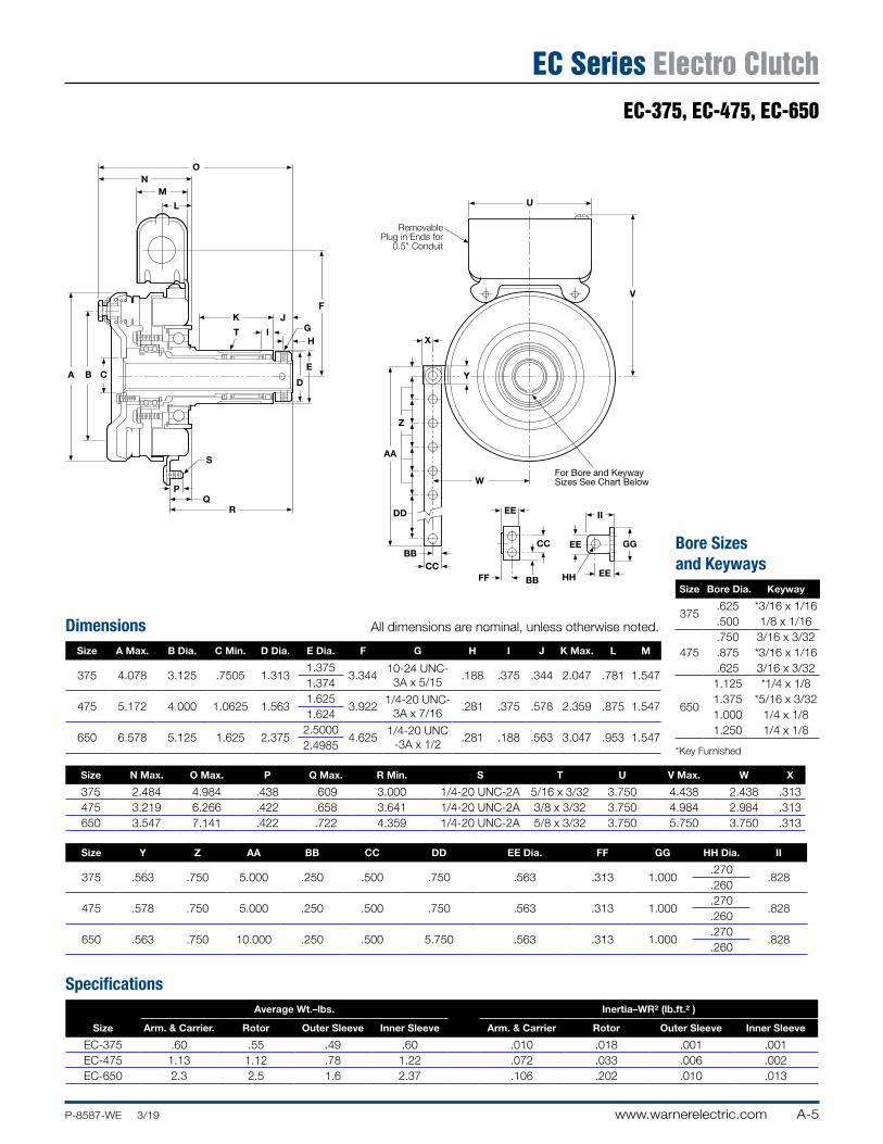
Dimensions All dimensions are nominal, unless otherwise noted.
Size A Max. B Dia. C Min. D Dia. E Dia. F G H I J K Max. L M
375 4.078 3.125 .7505 1.3131.375
3.34410-24 UNC- 3A x 5/15
.188 .375 .344 2.047 .781 1.5471.374
475 5.172 4.000 1.0625 1.5631.625
3.9221/4-20 UNC-
3A x 7/16.281 .375 .578 2.359 .875 1.547
1.624
650 6.578 5.125 1.625 2.3752.5000
4.6251/4-20 UNC
-3A x 1/2.281 .188 .563 3.047 .953 1.547
2.4985
Size N Max. O Max. P Q Max. R Min. S T U V Max. W X
375 2.484 4.984 .438 .609 3.000 1/4-20 UNC-2A 5/16 x 3/32 3.750 4.438 2.438 .313475 3.219 6.266 .422 .658 3.641 1/4-20 UNC-2A 3/8 x 3/32 3.750 4.984 2.984 .313650 3.547 7.141 .422 .722 4.359 1/4-20 UNC-2A 5/8 x 3/32 3.750 5.750 3.750 .313
Size Y Z AA BB CC DD EE Dia. FF GG HH Dia. II
375 .563 .750 5.000 .250 .500 .750 .563 .313 1.000.270
.828.260
475 .578 .750 5.000 .250 .500 .750 .563 .313 1.000.270
.828.260
650 .563 .750 10.000 .250 .500 5.750 .563 .313 1.000.270
.828.260
Specifications
Size
Average Wt.–lbs. Inertia–WR2 (lb.ft.2 )
Arm. & Carrier. Rotor Outer Sleeve Inner Sleeve Arm. & Carrier Rotor Outer Sleeve Inner Sleeve
EC-375 .60 .55 .49 .60 .010 .018 .001 .001EC-475 1.13 1.12 .78 1.22 .072 .033 .006 .002EC-650 2.3 2.5 1.6 2.37 .106 .202 .010 .013
EC Series Electro ClutchEC-375, EC-475, EC-650
EC-375, 475, 650 Dim11/5/99page 77
ON
M
L
CBA
S
R
PQ
D
E
FJ
GK
T IH
AA
CCBB
DD
Z
Y
X
RemovablePlug in Ends for
0.5" Conduit
U
V
FF BB
W
CC
EE
EE
EE
GG
HH
II
For Bore and KeywaySizes See Chart Below
Bore Sizes and KeywaysSize Bore Dia. Keyway
375.625 *3/16 x 1/16.500 1/8 x 1/16
475.750 3/16 x 3/32.875 *3/16 x 1/16.625 3/16 x 3/32
650
1.125 *1/4 x 1/81.375 *5/16 x 3/321.000 1/4 x 1/81.250 1/4 x 1/8
*Key Furnished
A-6 www.warnerelectric.com P-8587-WE 3/19
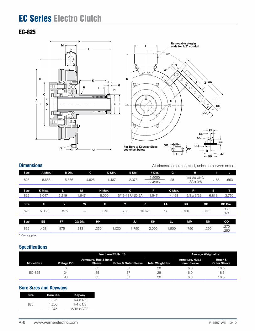
EC-825
EC Series Electro ClutchEC-825 Dim
N
B
D
C
A
R
K
L
G I
H
J
E F
QPO
S
TRemovable plug inends for 1/2" conduit
X
W
V
U
Z AA
CC
DD
Y
45°
For Bore & Keyway Sizessee chart below
MMOO
LL
DDHH
KKJJ
BB
FF
GGEE
II
M
Dimensions All dimensions are nominal, unless otherwise noted.
Size A Max. B Dia. C D Min. E Dia. F Dia. G H I J
825 8.656 5.656 4.625 1.437 2.3752.5000
.2811/4-20 UNC
-3A x 3/8.188 .563
2.4985
Size K Max. L M N Max. O P Q Max. R* S T
825 3.047 5.219 1.547 8.000 5/16-18 UNC-2A 1.547 4.468 5/8 x 3/32 6.813 3.750
Size U V W X Y Z AA BB CC DD Dia.
825 5.063 .875 — .375 .750 16.625 17 .750 .375.330 .321
Size EE FF GG Dia. HH II JJ KK LL MM NN OO
825 .438 .875 .313 .250 1.000 1.750 2.000 1.500 .750 .250.270 .260
* Key supplied
SpecificationsInertia–WR2 (lb. ft2) Average Weight–lbs.
Model Size Voltage DCArmature, Hub & Inner
Sleeve Rotor & Outer Sleeve Total Weight lbs.Armature, Hub&
Inner SleeveRotor &
Outer Sleeve
6 .35 .87 28 6.0 18.5EC-825 24 .35 .87 28 6.0 18.5
90 .35 .87 28 6.0 18.5
Bore Sizes and KeywaysSize Bore Dia. Keyway
1.125 1/4 x 1/8825 1.250 1/4 x 1/8
1.375 5/16 x 3/32
A-7www.warnerelectric.comP-8587-WE 3/19
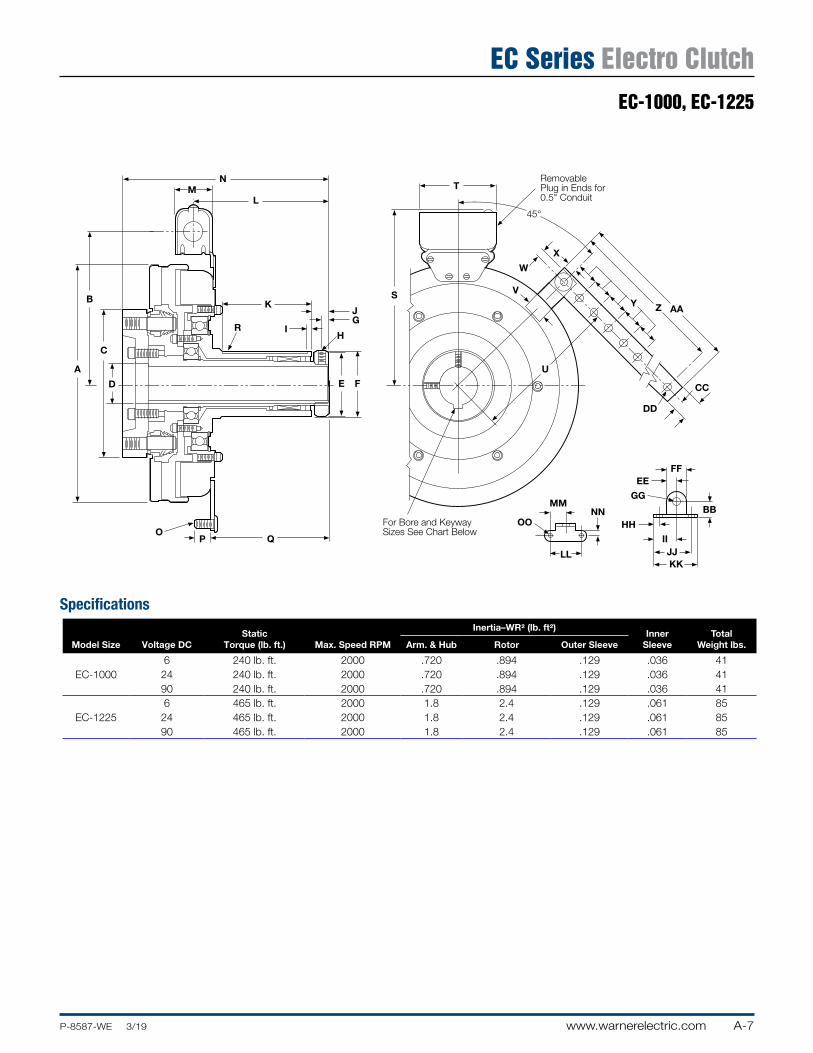
EC-1000, EC-1225
EC Series Electro Clutch
EC-1000,1225 Dim11/5/99page 82
A
D
C
B
P QO
E F
RH
JG
I
K
N
LM
For Bore and KeywaySizes See Chart Below
S
T
45°
W
AAZY
DD
CC
V
U
MM
OO
LL
NN
KKJJ
II
HH
BBGG
FFEE
RemovablePlug in Ends for0.5" Conduit
X
Specifications
Model Size Voltage DCStatic
Torque (lb. ft.) Max. Speed RPM
Inertia–WR2 (lb. ft2)Inner
SleeveTotal
Weight lbs.Arm. & Hub Rotor Outer Sleeve
6 240 lb. ft. 2000 .720 .894 .129 .036 41EC-1000 24 240 lb. ft. 2000 .720 .894 .129 .036 41
90 240 lb. ft. 2000 .720 .894 .129 .036 416 465 lb. ft. 2000 1.8 2.4 .129 .061 85
EC-1225 24 465 lb. ft. 2000 1.8 2.4 .129 .061 8590 465 lb. ft. 2000 1.8 2.4 .129 .061 85

A-8 www.warnerelectric.com P-8587-WE 3/19
EC-1000, EC-1225
EC Series Electro Clutch
Dimensions All dimensions are nominal, unless otherwise noted.
Size A Max. B Dia. C D Min. E Dia. F Dia. G H I J K Max. L M
1000 10.328 6.531 6.344 1.750 2.8752.9375
.3445/16-18 UNC
-3A x 3/8.188 .750 3.969 6.000 1.547
2.9365
1225 12.672 7.531 6.969 2.234 3.6253.750
.4065/81-16 UNC
-3A x 3/4.375 .859 5.219 7.781 1.547
3.749
Size N Max. O P Q Max. R* S T U V W X Y
1000 9.031 5/16-18 UNC-2A 1.547 5.281 3/4 x 1/8 7.688 3.750 6.125 .875 .344 .375 .750
1225 11.016 5/16-18 UNC-2A 1.547 7.047 7/8 x /8 8.688 3.750 7.000 .875 .344 .375 .750
Size Z AA BB CC DD Dia. EE FF GG Dia. HH II JJ KK LL MM NN OO
1000 16.625 17 .750 .375.330
.438 .875 .313 .250 1.000 1.750 2.000 1.500 .750 .250.270
.321 .260
1225 16.625 17 .750 .375.330
.438 .875 .313 .250 1.000 1.750 2.000 1.500 .750 .250.270
.321 .260
* Key supplied
Bore Sizes and KeywaySize Bore Dia. Keyway
1.375 *5/16 x 5/321000 1.500 *3/8 x 11/64
1.625 *3/8 x 1/81.625 *3/8 x 5/32
1225 1.875 *1/2 x 1/42.125 *1/2 x 3/16
*Key Furnished
A-9www.warnerelectric.comP-8587-WE 3/19
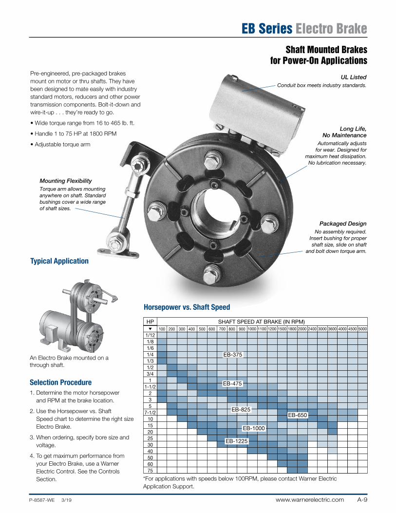
Shaft Mounted Brakes for Power-On Applications
EB Series Electro Brake
An Electro Brake mounted on a through shaft.
Selection Procedure1. Determine the motor horsepower
and RPM at the brake location.
2. Use the Horsepower vs. Shaft Speed chart to determine the right size Electro Brake.
3. When ordering, specify bore size and voltage.
4. To get maximum performance from your Electro Brake, use a Warner Electric Control. See the Controls Section.
Typical Application
EB HP/Shaft Speed Chart11/14/99page 86
1/121/81/61/41/31/23/41
1-1/2235
7-1/2101520253040506075
HP
Horsepower vs. Shaft Speed
SHAFT SPEED AT BRAKE (IN RPM)
EB-375
EB-475
EB-650EB-825
EB-1225
EB-1000
100 1000200 300 400 500 600 700 800 900 1100 1200 1500 1800 2000 2400 3000 3600 4000 4500 5000
Pre-engineered, pre-packaged brakes mount on motor or thru shafts. They have been designed to mate easily with industry standard motors, reducers and other power transmission components. Bolt-it-down and wire-it-up . . . they’re ready to go.
• Wide torque range from 16 to 465 lb. ft.
• Handle 1 to 75 HP at 1800 RPM
• Adjustable torque arm
Mounting FlexibilityTorque arm allows mounting anywhere on shaft. Standard bushings cover a wide range of shaft sizes.
UL ListedConduit box meets industry standards.
Long Life, No Maintenance
Automatically adjusts for wear. Designed for
maximum heat dissipation. No lubrication necessary.
Packaged DesignNo assembly required.
Insert bushing for proper shaft size, slide on shaft
and bolt down torque arm.
Horsepower vs. Shaft Speed
*For applications with speeds below 100RPM, please contact Warner Electric Application Support.
A-10 www.warnerelectric.com P-8587-WE 3/19
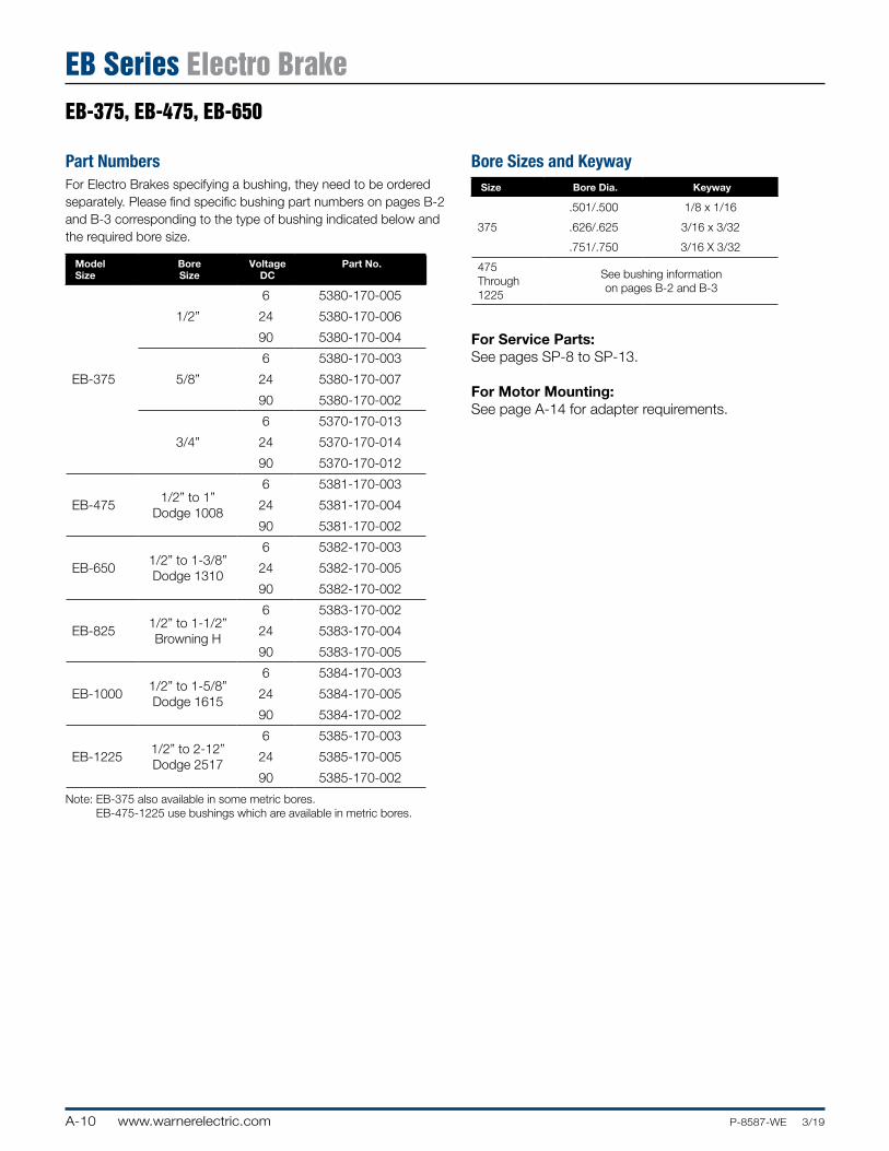
EB Series Electro BrakeEB-375, EB-475, EB-650
Part NumbersFor Electro Brakes specifying a bushing, they need to be ordered separately. Please find specific bushing part numbers on pages B-2 and B-3 corresponding to the type of bushing indicated below and the required bore size.
Model Size
Bore Size
Voltage DC
Part No.
EB-375
1/2”
6 5380-170-005
24 5380-170-006
90 5380-170-004
5/8”
6 5380-170-003
24 5380-170-007
90 5380-170-002
3/4”
6 5370-170-013
24 5370-170-014
90 5370-170-012
EB-4751/2” to 1”
Dodge 1008
6 5381-170-003
24 5381-170-004
90 5381-170-002
EB-6501/2” to 1-3/8” Dodge 1310
6 5382-170-003
24 5382-170-005
90 5382-170-002
EB-8251/2” to 1-1/2” Browning H
6 5383-170-002
24 5383-170-004
90 5383-170-005
EB-10001/2” to 1-5/8” Dodge 1615
6 5384-170-003
24 5384-170-005
90 5384-170-002
EB-12251/2” to 2-12” Dodge 2517
6 5385-170-003
24 5385-170-005
90 5385-170-002
Note: EB-375 also available in some metric bores. EB-475-1225 use bushings which are available in metric bores.
Bore Sizes and KeywaySize Bore Dia. Keyway
.501/.500 1/8 x 1/16
375 .626/.625 3/16 x 3/32
.751/.750 3/16 X 3/32
475 Through 1225
See bushing information on pages B-2 and B-3
For Service Parts:See pages SP-8 to SP-13.
For Motor Mounting:See page A-14 for adapter requirements.
A-11www.warnerelectric.comP-8587-WE 3/19
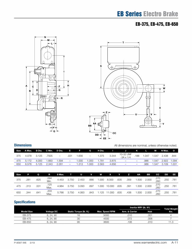
EB-375, EB-475, EB-650
EB Series Electro Brake
Dimensions All dimensions are nominal, unless otherwise noted.
Size A Max. B Dia. C Min. D Dia. E F G H Dia. I J K L M N Max. O
375 4.078 3.125 .7505 – .031 1.656 – 1.375 3.34410-32 UNF -3A x 1/4
.188 1.047 1.547 2.438 .844
475 5.172 4.000 1.663 1.594 – 1.000 1.000 1.781 3.875 – – .986 1.547 2.922 1.094650 6.578 5.125 2.343 2.281 – 1.313 1.000 2.563 4.656 – – .986 1.547 3.109 1.031
Size P Q R S Max. T U V W X Y Z AA BB CC DD EE
375 .281 .625.094 Min.
4.453 3.750 2.453 .666 1.000 8.000 .635 .359 1.500 2.000.270 .260
.250 .781
475 .313 .531.125 Max.
4.984 3.750 3.093 .697 1.000 10.000 .635 .391 1.500 2.000.270 .260
.250 .781
650 .344 .641.203 Max.
5.766 3.750 4.063 .843 1.125 11.000 .635 .438 1.500 2.000.270 .260
.250 .781
Specifications
Model Size Voltage DC Static Torque (lb. ft.) Max. Speed RPM
Inertia–WR2 (lb. ft2)Total Weight
lbs.Arm. & Carrier Hub
EB-375 6, 24, 90 16 5000 .010 .001 4EB-475 6, 24, 90 30 4500 .072 .006 7EB-650 6, 24, 90 95 3600 .106 .010 11.3
w
EB-375, 475, 650 Dim11/7/99page 88
NM
L
I
HF
GDC
B
A
R
O
P
Q
AABB
DD
EE
Z
CC
Y
VU
X
W
S
T
A-12 www.warnerelectric.com P-8587-WE 3/19
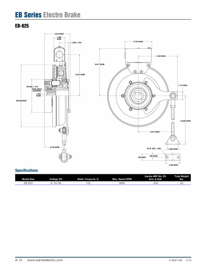
EB-825
EB Series Electro Brake
Specifications
Model Size Voltage DC Static Torque lb. ft. Max. Speed RPMInertia–WR2 (lb. ft2)
Arm. & HubTotal Weight
lbs.
EB-825 6, 24, 90 125 3600 .459 20
EB-825 Dim3/2014page 77
3.618 MAX
1.560NOM
1.269 ± .034
5.641 NOM
Ø8.646 MAX
Ø4.625 ± .015AVAILABLEBUSHING
1.250NOM
2.732 NOM
3.755 NOM
5.483 MAX
6.611 NOM
1.141 MAX
12.000 NOM
4.812 NOM
1.500 NOM
.950 MAX
2X Ø .265 ± .005
.460 NOM
2.050 MAX
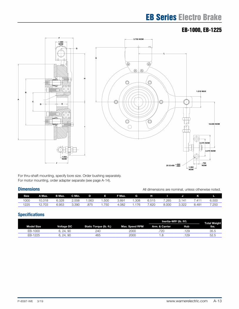
A-13www.warnerelectric.comP-8587-WE 3/19
EB-1000, EB-1225
EB Series Electro Brake
Adapter RequirementsFor thru-shaft mounting, specify bore size. Order bushing separately. For motor mounting, order adapter separate (see page A-14).
Dimensions All dimensions are nominal, unless otherwise noted.
Size A Max. B Max. C Min. D E F Max. G H I J K L
1000 10.318 6.328 2.558 1.563 1.500 3.891 1.308 6.515 7.265 3.141 7.411 6.5001225 12.703 6.953 3.390 .875 1.750 4.082 1.176 7.620 8.000 3.322 8.481 7.250
Specifications
Model Size Voltage DC Static Torque (lb. ft.) Max. Speed RPM
Inertia–WR2 (lb. ft2)Total Weight
lbs.Arm. & Carrier Hub
EB-1000 6, 24, 90 240 2000 .720 .129 35.5EB-1225 6, 24, 90 465 2000 1.8 .129 52.5
3.755 NOM
K
L
18.000 NOM
2.375 NOM
3.375 NOM
.750NOM2X Ø.408 +.005
-.004
1.516 MAX
1.362NOM
H
EB Series Electro BrakeEB-1000, EB-1225Page 78
A
B
D E
I
C
1.560 NOM
J
F
G
1.062NOM
A-14 www.warnerelectric.com P-8587-WE 3/19
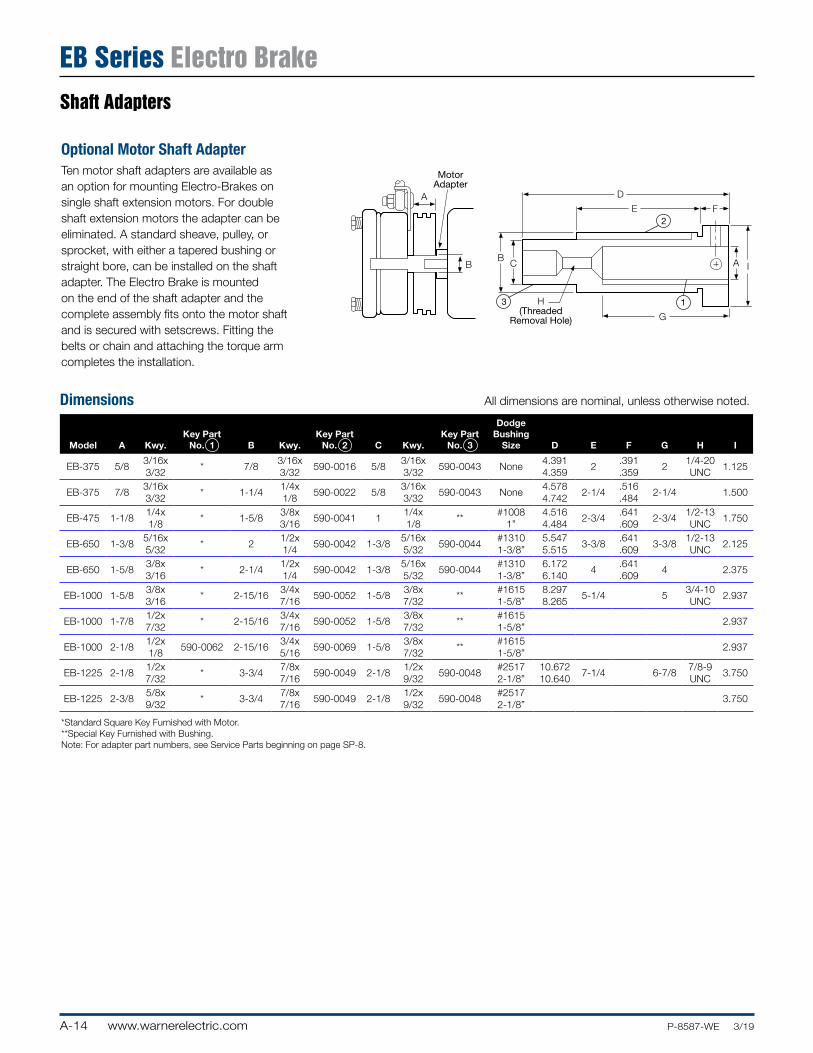
Shaft Adapters
EB Series Electro Brake
Optional Motor Shaft AdapterTen motor shaft adapters are available as an option for mounting Electro-Brakes on single shaft extension motors. For double shaft extension motors the adapter can be eliminated. A standard sheave, pulley, or sprocket, with either a tapered bushing or straight bore, can be installed on the shaft adapter. The Electro Brake is mounted on the end of the shaft adapter and the complete assembly fits onto the motor shaft and is secured with setscrews. Fitting the belts or chain and attaching the torque arm completes the installation.
Dimensions All dimensions are nominal, unless otherwise noted.
Model A Kwy.Key Part
No. 1 B Kwy.Key Part
No. 2 C Kwy.Key Part
No. 3
Dodge Bushing
Size D E F G H I
EB-375 5/83/16x 3/32
* 7/83/16x 3/32
590-0016 5/83/16x 3/32
590-0043 None4.391 4.359
2.391 .359
21/4-20 UNC
1.125
EB-375 7/83/16x 3/32
* 1-1/41/4x 1/8
590-0022 5/83/16x 3/32
590-0043 None4.578 4.742
2-1/4.516 .484
2-1/4 1.500
EB-475 1-1/81/4x 1/8
* 1-5/83/8x 3/16
590-0041 11/4x 1/8
**#1008
1”4.516 4.484
2-3/4.641 .609
2-3/41/2-13 UNC
1.750
EB-650 1-3/85/16x 5/32
* 21/2x 1/4
590-0042 1-3/85/16x 5/32
590-0044#1310 1-3/8”
5.547 5.515
3-3/8.641 .609
3-3/81/2-13 UNC
2.125
EB-650 1-5/83/8x 3/16
* 2-1/41/2x 1/4
590-0042 1-3/85/16x 5/32
590-0044#1310 1-3/8”
6.172 6.140
4.641 .609
4 2.375
EB-1000 1-5/83/8x 3/16
* 2-15/163/4x 7/16
590-0052 1-5/83/8x 7/32
**#1615 1-5/8”
8.297 8.265
5-1/4 53/4-10 UNC
2.937
EB-1000 1-7/81/2x 7/32
* 2-15/163/4x 7/16
590-0052 1-5/83/8x 7/32
**#1615 1-5/8”
2.937
EB-1000 2-1/81/2x 1/8
590-0062 2-15/163/4x 5/16
590-0069 1-5/83/8x 7/32
**#1615 1-5/8”
2.937
EB-1225 2-1/81/2x 7/32
* 3-3/47/8x 7/16
590-0049 2-1/81/2x 9/32
590-0048#2517 2-1/8”
10.672 10.640
7-1/4 6-7/87/8-9 UNC
3.750
EB-1225 2-3/85/8x 9/32
* 3-3/47/8x 7/16
590-0049 2-1/81/2x 9/32
590-0048#2517 2-1/8”
3.750
*Standard Square Key Furnished with Motor.**Special Key Furnished with Bushing.Note: For adapter part numbers, see Service Parts beginning on page SP-8.
MotorAdapter
A
B
EB Series Options Dim11/7/99page 87
D
E
B C
G
A I
F
H(Threaded
Removal Hole)
2
3 1
A-15www.warnerelectric.comP-8587-WE 3/19
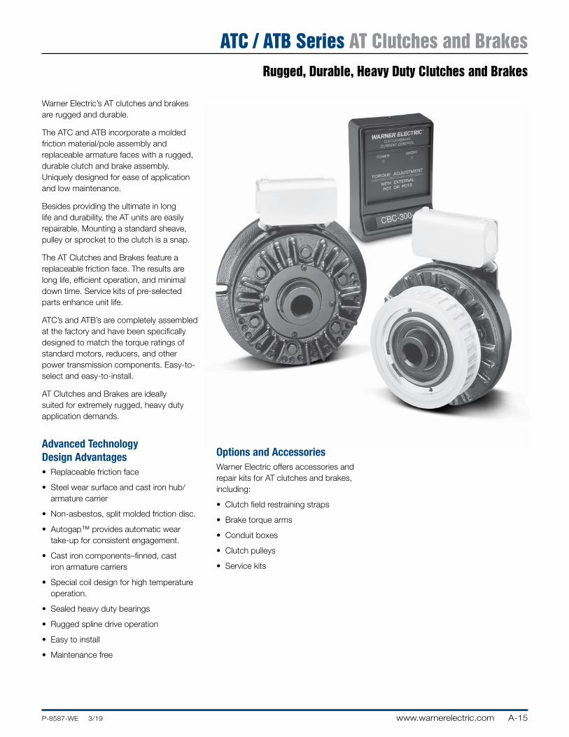
Rugged, Durable, Heavy Duty Clutches and Brakes
ATC / ATB Series AT Clutches and Brakes
Warner Electric’s AT clutches and brakes are rugged and durable.
The ATC and ATB incorporate a molded friction material/pole assembly and replaceable armature faces with a rugged, durable clutch and brake assembly. Uniquely designed for ease of application and low maintenance.
Besides providing the ultimate in long life and durability, the AT units are easily repairable. Mounting a standard sheave, pulley or sprocket to the clutch is a snap.
The AT Clutches and Brakes feature a replaceable friction face. The results are long life, efficient operation, and minimal down time. Service kits of pre-selected parts enhance unit life.
ATC’s and ATB’s are completely assembled at the factory and have been specifically designed to match the torque ratings of standard motors, reducers, and other power transmission components. Easy-to-select and easy-to-install.
AT Clutches and Brakes are ideally suited for extremely rugged, heavy duty application demands.
Advanced Technology Design Advantages• Replaceable friction face
• Steel wear surface and cast iron hub/armature carrier
• Non-asbestos, split molded friction disc.
• Autogap™ provides automatic wear take-up for consistent engagement.
• Cast iron components–finned, cast iron armature carriers
• Special coil design for high temperature operation.
• Sealed heavy duty bearings
• Rugged spline drive operation
• Easy to install
• Maintenance free
Options and AccessoriesWarner Electric offers accessories and repair kits for AT clutches and brakes, including:
• Clutch field restraining straps
• Brake torque arms
• Conduit boxes
• Clutch pulleys
• Service kits
A-16 www.warnerelectric.com P-8587-WE 3/19
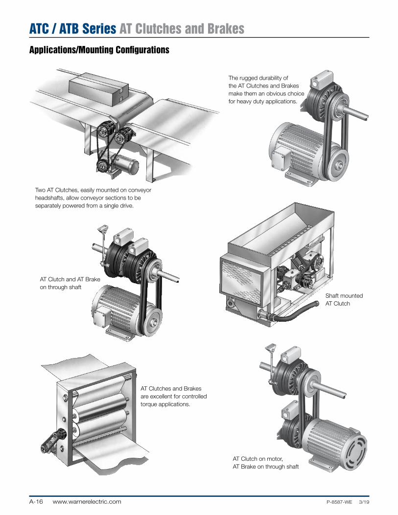
Applications/Mounting Configurations
ATC / ATB Series AT Clutches and Brakes
Two AT Clutches, easily mounted on conveyor headshafts, allow conveyor sections to be separately powered from a single drive.
AT Clutches and Brakes are excellent for controlled torque applications.
Shaft mounted AT Clutch
AT Clutch on motor, AT Brake on through shaft
AT Clutch and AT Brake on through shaft
The rugged durability of the AT Clutches and Brakes make them an obvious choice for heavy duty applications.
A-17www.warnerelectric.comP-8587-WE 3/19
Performance Advantages
ATC / ATB Series AT Clutches and Brakes
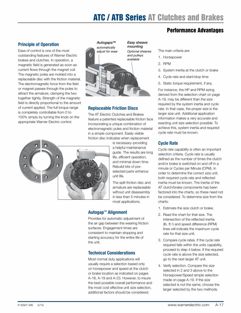
Principle of OperationEase of control is one of the most outstanding features of Warner Electric brakes and clutches. In operation, a magnetic field is generated as soon as current flows through the magnet coil. The magnetic poles are molded into a replaceable disc with the friction material. The electromagnetic force from the field or magnet passes through the poles to attract the armature, clamping the two together tightly. Strength of the magnetic field is directly proportional to the amount of current applied. The full torque range is completely controllable from 0 to 100% simply by turning the knob on the appropriate Warner Electric control.
Replaceable Friction DiscsThe AT Electric Clutches and Brakes feature a patented replaceable friction face incorporating a unique combination of electromagnetic poles and friction material in a simple component. Easily visible friction disc indicates when replacement
is necessary–providing a helpful maintenance guide. The results are long life, efficient operation, and minimal down time. Rebuild kits of pre-selected parts enhance unit life.
The split friction disc and armature are replaceable without unit disassembly in less than 5 minutes in most applications.
Autogap™ AlignmentProvides for automatic adjustment of the air gap between the wearing friction surfaces. Engagement times are consistent to maintain stopping and starting accuracy for the entire life of the unit.
Technical ConsiderationsMost normal duty applications will usually require a selection based only on horsepower and speed at the clutch or brake location as indicated on pages A-18, A-19 and A-23. However, to insure the best possible overall performance and the most cost effective unit size selection, additional factors should be considered.
The main criteria are:
1. Horsepower
2. RPM
3. System inertia at the clutch or brake
4. Cycle rate and start/stop time
5. Static torque requirement, if any.
For instance, the HP and RPM sizing derived from the selection chart on page A-19, may be different than the size required by the system inertia and cycle rate. In that case, the proper size is the larger size unit. Additional application information makes a very accurate and exacting unit size selection possible. To achieve this, system inertia and required cycle rate must be known.
Cycle RateCycle rate capability is often an important selection criteria. Cycle rate is usually defined as the number of times the clutch and/or brake is switched on and off in a minute or Cycles per Minute (CPM). In order to determine the correct size unit, both required cycle rate and reflected inertia must be known. The inertia of the AT clutch/brake components has been factored into the charts, so these need not be considered. To determine size from the charts:
1. Estimate the size clutch or brake.
2. Read the chart for that size. The intersection of the reflected inertia (lb. ft.2) and speed difference (RPM) lines will indicate the maximum cycle rate for that size unit.
3. Compare cycle rates. If the cycle rate required falls within the units capability, proceed to step 4 below. If the required cycle rate is above the size selected, go to the next larger AT unit.
4. Verify selection. Compare the size selected in 2 and 3 above to the Horsepower/Speed simple selection made on page A-19. If the size selected is not the same, choose the larger selected by the two methods.
Easy sheave mountingOptional sheaves and pulleys available
AutogapsTM
automatically adjust for wear
A-18 www.warnerelectric.com P-8587-WE 3/19
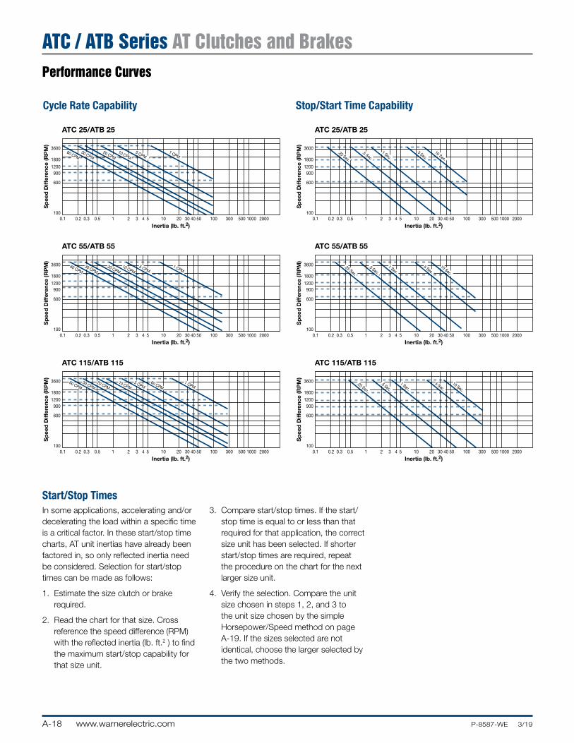
Performance Curves
ATC / ATB Series AT Clutches and Brakes
Cycle Rate Capability Stop/Start Time Capability
AT Clutch/Brake Curves11/14/99page 101
0.1 0.2 0.3 0.5
Sp
eed
Diff
eren
ce (R
PM
)
Inertia (lb. ft.2)
100
600
9001200
1800
3600
1 2 3 54 10 20 30 5040 100 300 500 1000 2000
0.1 0.2 0.3 0.5
Sp
eed
Diff
eren
ce (R
PM
)
Inertia (lb. ft.2)
600
9001200
1800
3600
1 2 3 54 10 20 30 5040 100 300 500 1000 2000
0.1 0.2 0.3 0.5
Sp
eed
Diff
eren
ce (R
PM
)
Inertia (lb. ft.2)
600
9001200
1800
3600
1 2 3 54 10 20 30 5040 100 300 500 1000 2000 0.1 0.2 0.3 0.5
Sp
eed
Diff
eren
ce (R
PM
)
Inertia (lb. ft.2)
600
9001200
1800
3600
1 2 3 54 10 20 30 5040 100 300 500 1000 2000
0.1 0.2 0.3 0.5
Sp
eed
Diff
eren
ce (R
PM
)
Inertia (lb. ft.2)
600
9001200
1800
3600
1 2 3 54 10 20 30 5040 100 300 500 1000 2000
0.1 0.2 0.3 0.5
Sp
eed
Diff
eren
ce (R
PM
)
Inertia (lb. ft.2)
600
9001200
1800
3600
1 2 3 54 10 20 30 5040 100 300 500 1000 2000
100
100 100
100
100
ATC 25/ATB 25 ATC 25/ATB 25
ATC 55/ATB 55 ATC 55/ATB 55
ATC 115/ATB 115 ATC 115/ATB 115
60 CPM30 CPM
20 CPM10 CPM
5 CPM1 CPM
60 CPM30 CPM
20 CPM10 CPM
5 CPM1 CPM
60 CPM30 CPM
20 CPM10 CPM
5 CPM60 CPM
1 CPM
.25 Sec.
.5 Sec.
1 Sec.5 Sec.
10 Sec.
.25 Sec.
.25 Sec.
.5 Sec.
1 Sec.5 Sec.
10 Sec.
.5 Sec.
1 Sec.5 Sec.
10 Sec.
Start/Stop TimesIn some applications, accelerating and/or decelerating the load within a specific time is a critical factor. In these start/stop time charts, AT unit inertias have already been factored in, so only reflected inertia need be considered. Selection for start/stop times can be made as follows:
1. Estimate the size clutch or brake required.
2. Read the chart for that size. Cross reference the speed difference (RPM) with the reflected inertia (lb. ft.2 ) to find the maximum start/stop capability for that size unit.
3. Compare start/stop times. If the start/stop time is equal to or less than that required for that application, the correct size unit has been selected. If shorter start/stop times are required, repeat the procedure on the chart for the next larger size unit.
4. Verify the selection. Compare the unit size chosen in steps 1, 2, and 3 to the unit size chosen by the simple Horsepower/Speed method on page A-19. If the sizes selected are not identical, choose the larger selected by the two methods.
A-19www.warnerelectric.comP-8587-WE 3/19
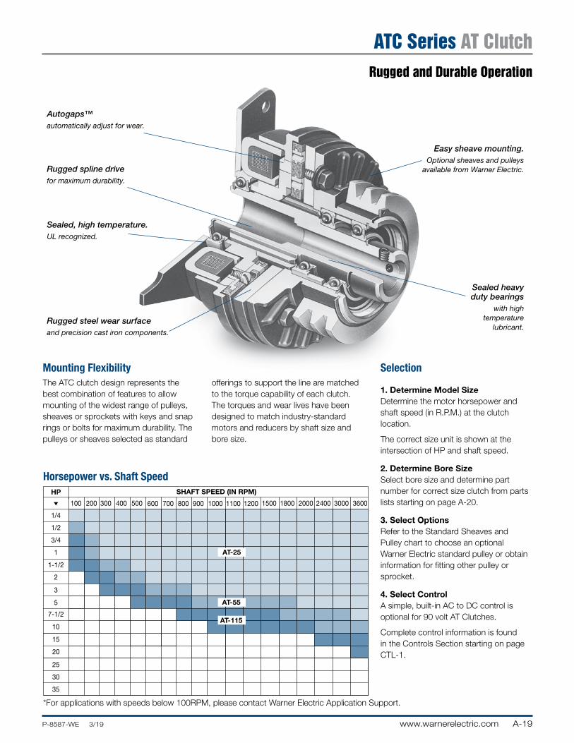
Rugged and Durable Operation
ATC Series AT Clutch
Mounting FlexibilityThe ATC clutch design represents the best combination of features to allow mounting of the widest range of pulleys, sheaves or sprockets with keys and snap rings or bolts for maximum durability. The pulleys or sheaves selected as standard
offerings to support the line are matched to the torque capability of each clutch. The torques and wear lives have been designed to match industry-standard motors and reducers by shaft size and bore size.
Selection
1. Determine Model SizeDetermine the motor horsepower and shaft speed (in R.P.M.) at the clutch location.
The correct size unit is shown at the intersection of HP and shaft speed.
2. Determine Bore SizeSelect bore size and determine part number for correct size clutch from parts lists starting on page A-20.
3. Select OptionsRefer to the Standard Sheaves and Pulley chart to choose an optional Warner Electric standard pulley or obtain information for fitting other pulley or sprocket.
4. Select ControlA simple, built-in AC to DC control is optional for 90 volt AT Clutches.
Complete control information is found in the Controls Section starting on page CTL-1.
AT Clutch HP/SS Chart11/14/99page 102
AT-205
AT-305
1/4
1/2
3/4
1
1-1/2
2
3
5
7-1/2
10
15
20
25
30
35
HP
Horsepower vs. Shaft Speed
100 600 1000 1100 1200 1500 1800 2000 2400 3000 3600200 300 400 500 700 800 900
SHAFT SPEED (IN RPM)
AT-25
AT-55
AT-115
Horsepower vs. Shaft Speed
Autogaps™automatically adjust for wear.
Rugged spline drivefor maximum durability.
Sealed, high temperature.UL recognized.
Rugged steel wear surfaceand precision cast iron components.
Sealed heavy duty bearings
with high temperature
lubricant.
Easy sheave mounting.Optional sheaves and pulleys
available from Warner Electric.
*For applications with speeds below 100RPM, please contact Warner Electric Application Support.
A-20 www.warnerelectric.com P-8587-WE 3/19
Selection/Ordering Information
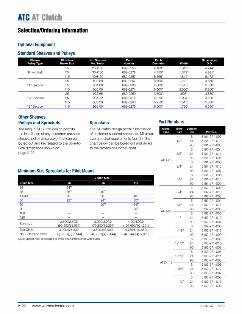
ATC AT Clutch
Standard Sheaves and PulleysSheave
Pulley TypeClutch or
Brake SizeNo. Grooves
No. TeethPart
NumberPitch
Diameter WidthDimensions
O.D.
25 26H100 689-0256 4.138” 1.312” 4.244”Timing Belt 55 30H100 689-0278 4.755” 1.312” 4.881”
115 40H150 689-0257 6.366” 1.812” 6.472”25 1G3.60 689-0267 3.600” .750” 3.850”
“A” Section 55 2G4.80 689-0308 4.800” 1.445” 5.050”115 3G6.00 689-0271 6.000” 2.000” 6.250”25 1G3.65 689-0259 3.600” .695” 3.650”
“3V” Section 55 2G4.12 689-0315 4.070” 1.094” 4.120”115 3G5.30 689-0263 5.250” 1.515” 5.300”
“B” Section 115 2G6.00 689-0275 6.000” 1.750” 6.350”
Optional Equipment
Part NumbersModel Size
Bore Size
Voltage DC Part No.
ATC-25
6 5161-271-0021/2” 24 5161-271-010
90 5161-271-0036 5161-271-004
5/8” 24 5161-271-01190 5161-271-0056 5161-271-006
3/4” 24 5161-271-01290 5161-271-0076 5161-271-008
7/8” 24 5161-271-01390 5161-271-009
ATC-55
6 5162-271-0023/4” 24 5162-271-010
90 5162-271-0036 5162-271-004
7/8” 24 5162-271-01190 5162-271-0056 5162-271-006
1” 24 5162-271-01290 5162-271-0076 5162-271-008
1-1/8” 24 5162-271-01390 5162-271-009
ATC-115
6 5163-271-0021-1/8” 24 5163-271-010
90 5163-271-0036 5163-271-004
1-1/4” 24 5163-271-01190 5163-271-0056 5163-271-006
1-3/8” 24 5163-271-01290 5163-271-0076 5163-271-008
1-1/2” 24 5163-271-01390 5163-271-009
Minimum Size Sprockets for Pilot MountClutch Size
Chain Size 25 55 115
25 54T — —35 35T 40T —41/40 28T 30T 40T50 22T 24T 30T60 — 20T 24T80 — — 20T100 — — —120 — — —
Bore size2.500/2.502/
(63.500/63.551)3.000/3.002/
(76.200/76.251)4.00/4.002/
(101.600/101.651)Bolt Circle 3.000/(76.200) 3.500/(88.900) 4.750/(120.650)No. Holes and Sizes (3) .281/[(3) 7.144] (4) .281/[(4) 7.144] (4) .344/[(4) 8.731]
Note: Spacer may be required to avoid chain interference with clutch.
Other Sheaves, Pulleys and SprocketsThe unique AT Clutch design permits the installation of any customer provided sheave, pulley or sprocket that can be bored out and key seated to the Bore-to-Size dimensions shown on page A-22.
SprocketsThe AT clutch design permits installation of customer supplied sprockets. Minimum size sprocket requirements found in the chart below can be bored out and drilled to the dimensions in that chart.
A-21www.warnerelectric.comP-8587-WE 3/19
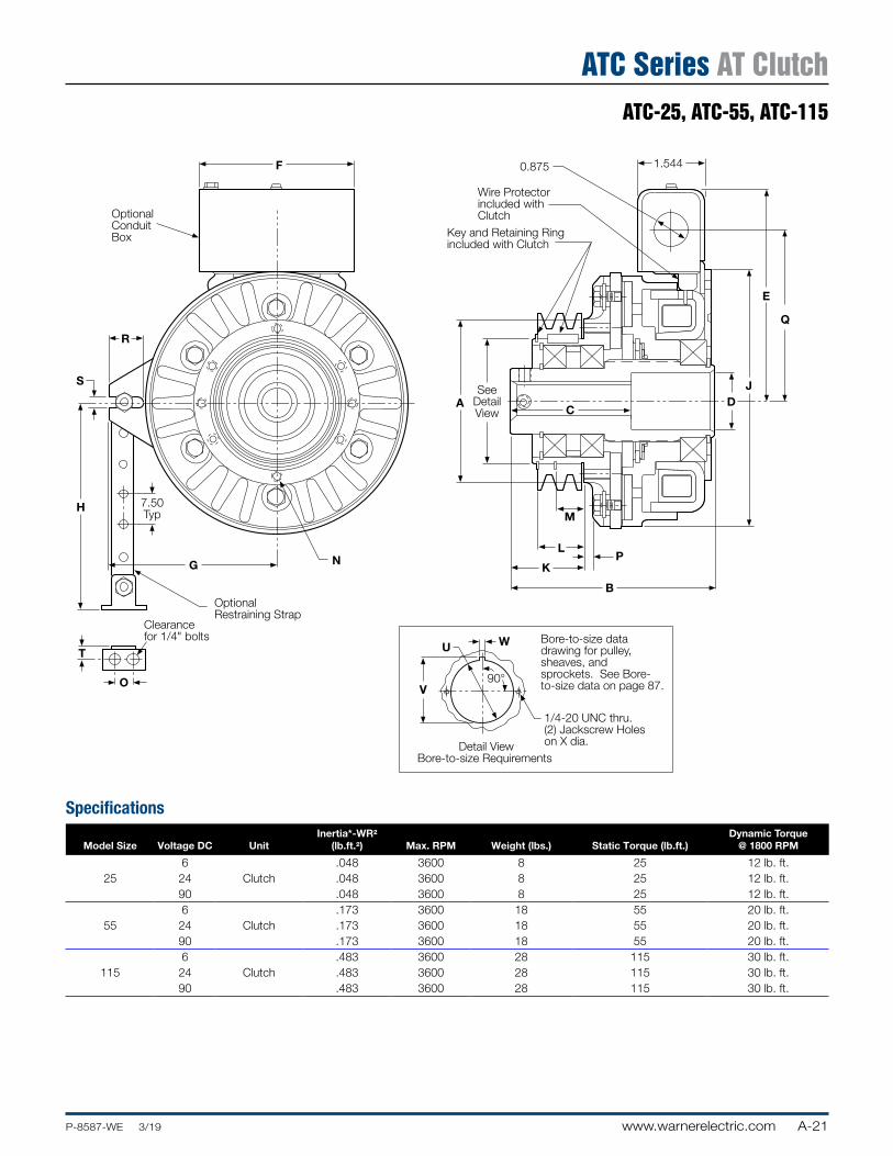
ATC-25, ATC-55, ATC-115
ATC Series AT Clutch
Clearancefor 1/4" bolts
O
T
OptionalRestraining Strap
G N
H 7.50Typ
S
R
OptionalConduitBox
F 0.875
Wire Protectorincluded withClutch
Key and Retaining Ringincluded with Clutch
1.544
SeeDetailView
AC
M
L
KP
B
DJ
E
Q
WU
V90°
1/4-20 UNC thru.(2) Jackscrew Holeson X dia.
ATC 25, 55, 115 Dim11/7/99page 104
Detail ViewBore-to-size Requirements
Bore-to-size datadrawing for pulley,sheaves, andsprockets. See Bore-to-size data on page 87.
Specifications
Model Size Voltage DC UnitInertia*-WR2
(lb.ft.2) Max. RPM Weight (lbs.) Static Torque (lb.ft.)Dynamic Torque
@ 1800 RPM
6 .048 3600 8 25 12 lb. ft.25 24 Clutch .048 3600 8 25 12 lb. ft.
90 .048 3600 8 25 12 lb. ft.6 .173 3600 18 55 20 lb. ft.
55 24 Clutch .173 3600 18 55 20 lb. ft.90 .173 3600 18 55 20 lb. ft.6 .483 3600 28 115 30 lb. ft.
115 24 Clutch .483 3600 28 115 30 lb. ft.90 .483 3600 28 115 30 lb. ft.
A-22 www.warnerelectric.com P-8587-WE 3/19
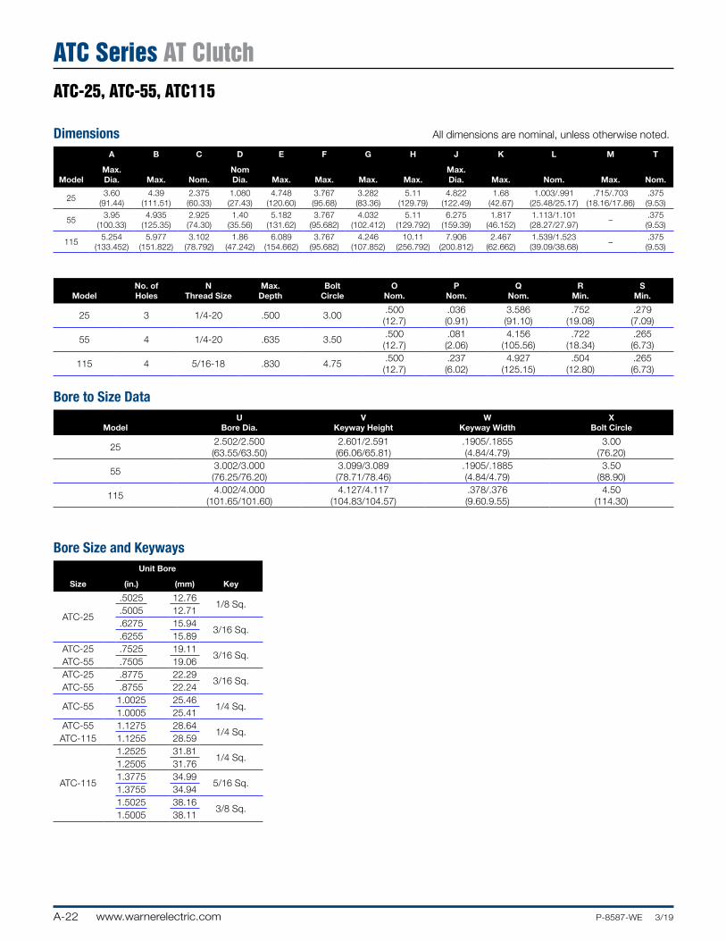
ATC-25, ATC-55, ATC115
ATC Series AT Clutch
Dimensions All dimensions are nominal, unless otherwise noted.
A B C D E F G H J K L M T
ModelMax. Dia. Max. Nom.
Nom Dia. Max. Max. Max. Max.
Max. Dia. Max. Nom. Max. Nom.
253.60
(91.44)4.39
(111.51)2.375 (60.33)
1.080 (27.43)
4.748 (120.60)
3.767 (95.68)
3.282 (83.36)
5.11 (129.79)
4.822 (122.49)
1.68 (42.67)
1.003/.991 (25.48/25.17)
.715/.703 (18.16/17.86)
.375 (9.53)
553.95
(100.33)4.935
(125.35)2.925 (74.30)
1.40 (35.56)
5.182 (131.62)
3.767 (95.682)
4.032 (102.412)
5.11 (129.792)
6.275 (159.39)
1.817 (46.152)
1.113/1.101 (28.27/27.97)
–.375 (9.53)
1155.254
(133.452)5.977
(151.822)3.102
(78.792)1.86
(47.242)6.089
(154.662)3.767
(95.682)4.246
(107.852)10.11
(256.792)7.906
(200.812)2.467
(62.662)1.539/1.523 (39.09/38.68)
–.375 (9.53)
ModelNo. of Holes
N Thread Size
Max. Depth
Bolt Circle
O Nom.
P Nom.
Q Nom.
R Min.
S Min.
25 3 1/4-20 .500 3.00.500 (12.7)
.036 (0.91)
3.586 (91.10)
.752 (19.08)
.279 (7.09)
55 4 1/4-20 .635 3.50.500 (12.7)
.081 (2.06)
4.156 (105.56)
.722 (18.34)
.265 (6.73)
115 4 5/16-18 .830 4.75.500 (12.7)
.237 (6.02)
4.927 (125.15)
.504 (12.80)
.265 (6.73)
Bore to Size Data
ModelU
Bore Dia.V
Keyway HeightW
Keyway WidthX
Bolt Circle
252.502/2.500 (63.55/63.50)
2.601/2.591 (66.06/65.81)
.1905/.1855 (4.84/4.79)
3.00 (76.20)
553.002/3.000 (76.25/76.20)
3.099/3.089 (78.71/78.46)
.1905/.1885 (4.84/4.79)
3.50 (88.90)
1154.002/4.000
(101.65/101.60)4.127/4.117
(104.83/104.57).378/.376 (9.60.9.55)
4.50 (114.30)
Bore Size and Keyways
Size
Unit Bore
Key(in.) (mm)
ATC-25
.5025 12.761/8 Sq.
.5005 12.71
.6275 15.943/16 Sq.
.6255 15.89ATC-25 .7525 19.11
3/16 Sq.ATC-55 .7505 19.06ATC-25 .8775 22.29
3/16 Sq.ATC-55 .8755 22.24
ATC-551.0025 25.46
1/4 Sq.1.0005 25.41
ATC-55 1.1275 28.641/4 Sq.
ATC-115 1.1255 28.59
ATC-115
1.2525 31.811/4 Sq.
1.2505 31.761.3775 34.99
5/16 Sq.1.3755 34.941.5025 38.16
3/8 Sq.1.5005 38.11
A-23www.warnerelectric.comP-8587-WE 3/19
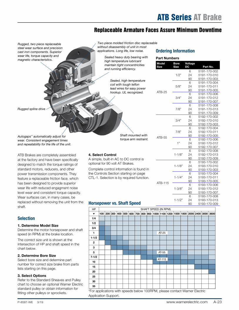
Replaceable Armature Faces Assure Minimum Downtime
ATB Series AT Brake
Ordering InformationPart NumbersModel Size
Bore Size
Voltage DC Part No.
ATB-25
6 5191-170-0021/2” 24 5191-170-010
90 5191-170-0036 5191-170-004
5/8” 24 5191-170-01190 5191-170-0056 5191-170-006
3/4” 24 5191-170-01290 5191-170-0076 5191-170-008
7/8” 24 5191-170-01390 5191-170-009
ATB-55
6 5192-170-0023/4” 24 5192-170-010
90 5192-170-0036 5192-170-004
7/8” 24 5192-170-01190 5192-170-0056 5192-170-006
1” 24 5192-170-01290 5192-170-0076 5192-170-008
1-1/8” 24 5192-170-01390 5192-170-009
ATB-115
6 5193-170-0021-1/8” 24 5193-170-010
90 5193-170-0036 5193-170-004
1-1/4” 24 5193-170-01190 5193-170-0056 5193-170-006
1-3/8” 24 5193-170-01290 5193-170-0076 5193-170-008
1-1/2” 24 5193-170-01390 5193-170-009
ATB Brakes are completely assembled at the factory and have been specifically designed to match the torque ratings of standard motors, reducers, and other power transmission components. They feature a replaceable friction face. which has been designed to provide superior wear life with reduced engagment noise level wear and consistent torque capacity. Wear surfaces can, in many cases, be replaced without removing the unit from the shaft.
Selection1. Determine Model SizeDetermine the motor horsepower and shaft speed (in RPM) at the brake location.
The correct size unit is shown at the intersection of HP and shaft speed in the chart below.
2. Determine Bore SizeSelect bore size and determine part number for correct size brake from parts lists starting on this page.
3. Select OptionsRefer to the Standard Sheaves and Pulley chart to choose an optional Warner Electric standard pulley or obtain information for fitting other pulleys or sprockets.
AT Brake HP/SS Chart11/14/99page 108
AT-205
AT-305
1/4
1/2
3/4
1
1-1/2
2
3
5
7-1/2
10
15
20
25
30
35
HP
Horsepower vs. Shaft Speed
100 600 1000 1100 1200 1500 1800 2000 2400 3000 3600200 300 400 500 700 800 900
SHAFT SPEED (IN RPM)
AT-25
AT-55
AT-115
Horsepower vs. Shaft Speed
AutogapsTM automatically adjust for wear. Consistent engagement times and repeatability for the life of the unit.
Rugged, two piece replaceable steel wear surface and precision cast iron components. Superior wear life, torque capacity and magnetic characterisitcs.
Two piece molded friction disc replaceable without disassembly of unit in most applications. Long life, low noise.
Rugged spline drive
Sealed heavy duty bearing with high temperature lubricant maintain tight concentricities and running efficiency.
Sealed, high temperature coil with tough teflon lead wires for easy power hookup. UL recognized.
Shaft mounted with torque arm restraint.
4. Select ControlA simple, built-in AC to DC control is optional for 90 volt AT Brakes.
Complete control information is found in the Controls Section starting on page CTL-1. Selection is by required function.
*For applications with speeds below 100RPM, please contact Warner Electric Application Support.
A-24 www.warnerelectric.com P-8587-WE 3/19
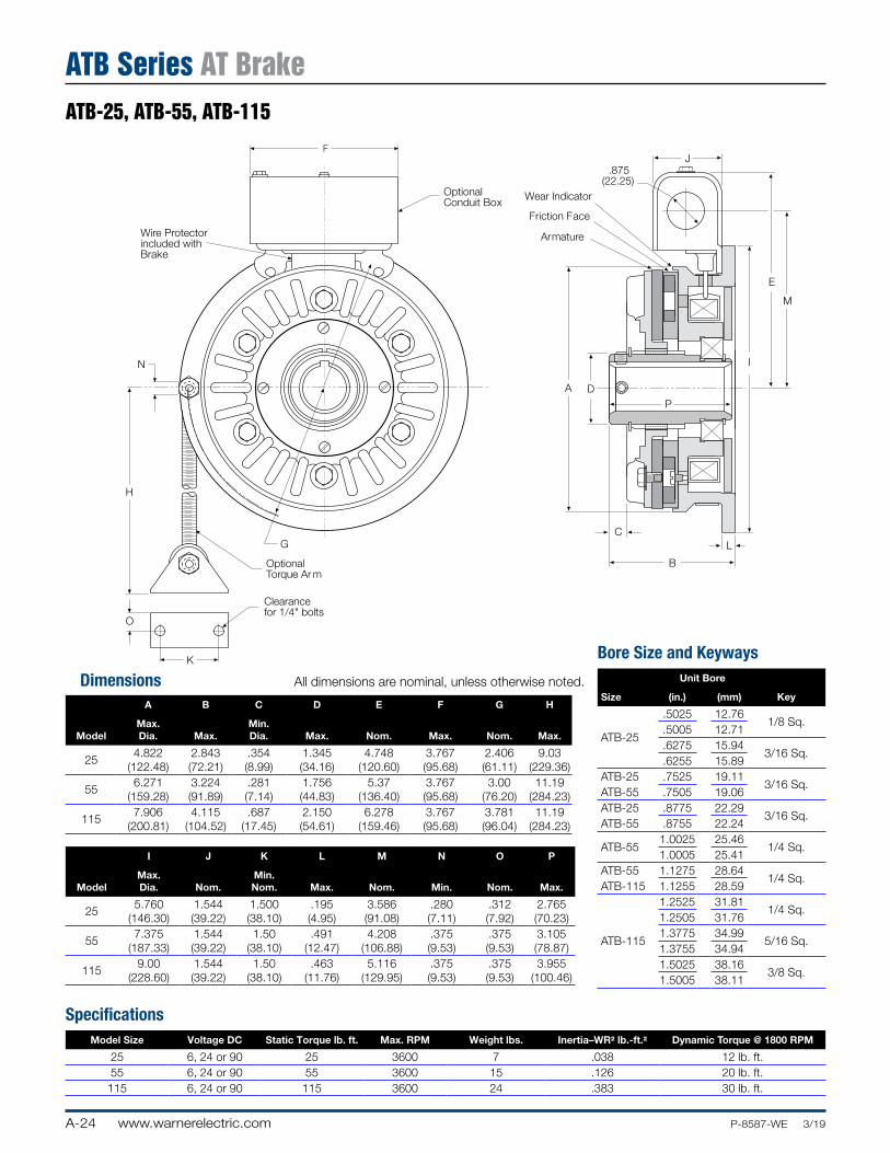
A B C D E F G H
ModelMax. Dia. Max.
Min. Dia. Max. Nom. Max. Nom. Max.
254.822
(122.48)2.843 (72.21)
.354 (8.99)
1.345 (34.16)
4.748 (120.60)
3.767 (95.68)
2.406 (61.11)
9.03 (229.36)
556.271
(159.28)3.224 (91.89)
.281 (7.14)
1.756 (44.83)
5.37 (136.40)
3.767 (95.68)
3.00 (76.20)
11.19 (284.23)
1157.906
(200.81)4.115
(104.52).687
(17.45)2.150 (54.61)
6.278 (159.46)
3.767 (95.68)
3.781 (96.04)
11.19 (284.23)
I J K L M N O P
ModelMax. Dia. Nom.
Min. Nom. Max. Nom. Min. Nom. Max.
255.760
(146.30)1.544 (39.22)
1.500 (38.10)
.195 (4.95)
3.586 (91.08)
.280 (7.11)
.312 (7.92)
2.765 (70.23)
557.375
(187.33)1.544 (39.22)
1.50 (38.10)
.491 (12.47)
4.208 (106.88)
.375 (9.53)
.375 (9.53)
3.105 (78.87)
1159.00
(228.60)1.544 (39.22)
1.50 (38.10)
.463 (11.76)
5.116 (129.95)
.375 (9.53)
.375 (9.53)
3.955 (100.46)
SpecificationsModel Size Voltage DC Static Torque lb. ft. Max. RPM Weight lbs. Inertia–WR2 lb.-ft.2 Dynamic Torque @ 1800 RPM
25 6, 24 or 90 25 3600 7 .038 12 lb. ft.55 6, 24 or 90 55 3600 15 .126 20 lb. ft.115 6, 24 or 90 115 3600 24 .383 30 lb. ft.
Wire Protectorincluded withBrake
OptionalConduit Box
F
G
H
B
A DP
LC
I
E
M
J
Wear Indicator
Friction Face
Armature
.875(22.25)
O
K
Clearancefor 1/4" bolts
OptionalTorque Ar m
N
A-112
Dimensions All dimensions are nominal, unless otherwise noted.
ATB-25, ATB-55, ATB-115
ATB Series AT Brake
Bore Size and Keyways
Size
Unit Bore
Key(in.) (mm)
ATB-25
.5025 12.761/8 Sq.
.5005 12.71
.6275 15.943/16 Sq.
.6255 15.89ATB-25 .7525 19.11
3/16 Sq.ATB-55 .7505 19.06ATB-25 .8775 22.29
3/16 Sq.ATB-55 .8755 22.24
ATB-551.0025 25.46
1/4 Sq.1.0005 25.41
ATB-55 1.1275 28.641/4 Sq.
ATB-115 1.1255 28.59
ATB-115
1.2525 31.811/4 Sq.
1.2505 31.761.3775 34.99
5/16 Sq.1.3755 34.941.5025 38.16
3/8 Sq.1.5005 38.11
A-25www.warnerelectric.comP-8587-WE 3/19
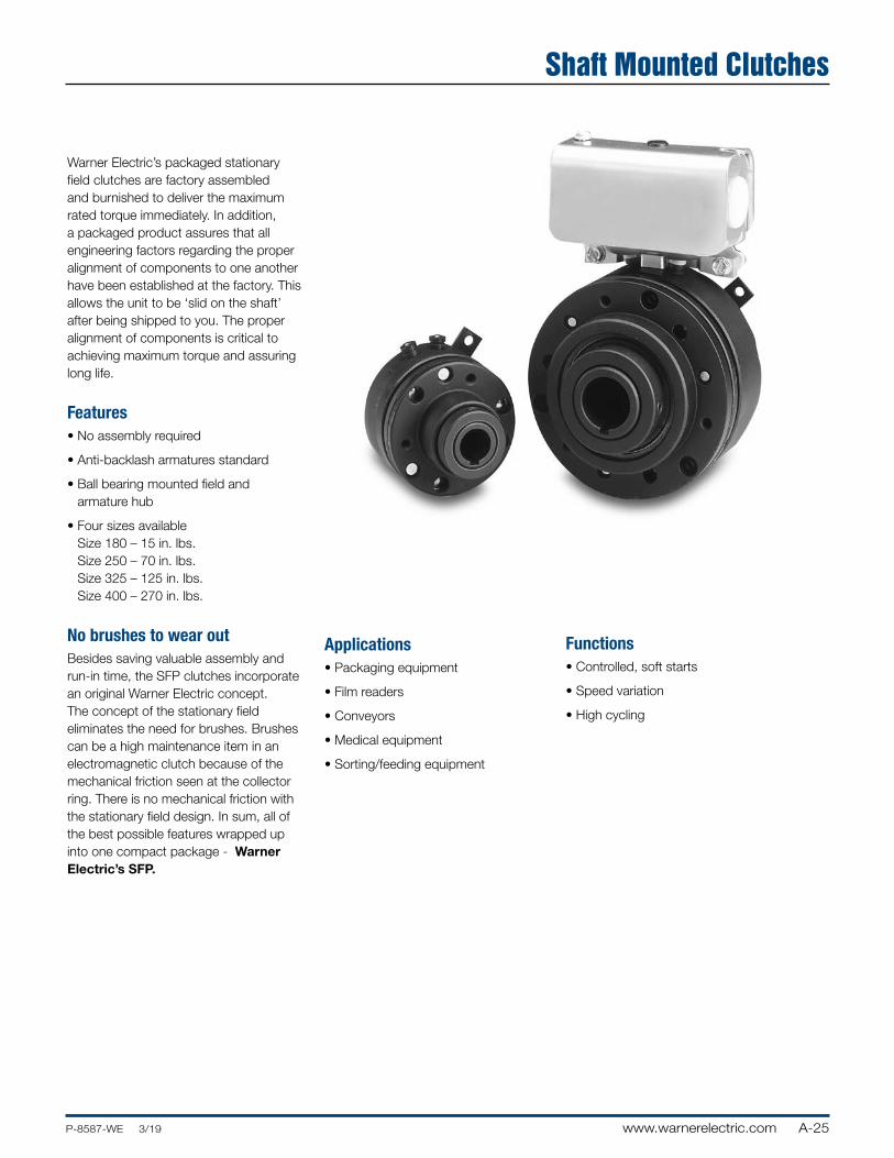
Warner Electric’s packaged stationary field clutches are factory assembled and burnished to deliver the maximum rated torque immediately. In addition, a packaged product assures that all engineering factors regarding the proper alignment of components to one another have been established at the factory. This allows the unit to be ‘slid on the shaft’ after being shipped to you. The proper alignment of components is critical to achieving maximum torque and assuring long life.
Features• No assembly required
• Anti-backlash armatures standard
• Ball bearing mounted field and armature hub
• Four sizes available Size 180 – 15 in. lbs. Size 250 – 70 in. lbs. Size 325 – 125 in. lbs. Size 400 – 270 in. lbs.
No brushes to wear outBesides saving valuable assembly and run-in time, the SFP clutches incorporate an original Warner Electric concept. The concept of the stationary field eliminates the need for brushes. Brushes can be a high maintenance item in an electromagnetic clutch because of the mechanical friction seen at the collector ring. There is no mechanical friction with the stationary field design. In sum, all of the best possible features wrapped up into one compact package - Warner Electric’s SFP.
Applications• Packaging equipment
• Film readers
• Conveyors
• Medical equipment
• Sorting/feeding equipment
Functions• Controlled, soft starts
• Speed variation
• High cycling
Shaft Mounted Clutches
A-26 www.warnerelectric.com P-8587-WE 3/19
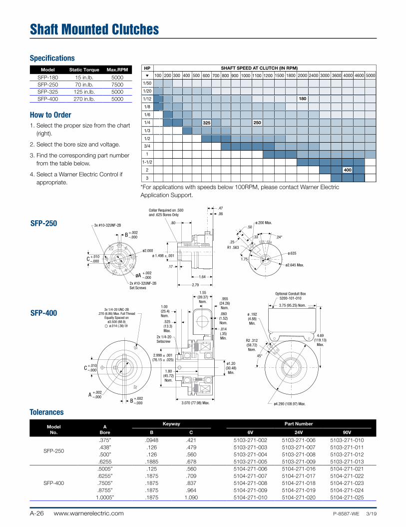
Shaft Mounted Clutches
SpecificationsModel Static Torque Max.RPM
SFP-180 15 in.lb. 5000SFP-250 70 in.lb. 7500SFP-325 125 in.lb. 5000SFP-400 270 in.lb. 5000
How to Order1. Select the proper size from the chart
(right).
2. Select the bore size and voltage.
3. Find the corresponding part number from the table below.
4. Select a Warner Electric Control if appropriate.
Tolerances
Model No.
A Bore
Keyway Part Number
B C 6V 24V 90V
SFP-250
.375” .0948 .421 5103-271-002 5103-271-006 5103-271-010
.438” .126 .479 5103-271-003 5103-271-007 5103-271-011
.500” .126 .560 5103-271-004 5103-271-008 5103-271-012.6255 .1885 .678 5103-271-005 5103-271-009 5103-271-013
SFP-400
.5005” .125 .560 5104-271-006 5104-271-016 5104-271-021
.6255” .1875 .709 5104-271-007 5104-271-017 5104-271-022
.7505” .1875 .837 5104-271-008 5104-271-018 5104-271-023
.8755” .1875 .964 5104-271-009 5104-271-019 5104-271-0241.0005” .1875 1.090 5104-271-010 5104-271-020 5104-271-025
1/50
1/20
1/12
1/8
1/6
1/4
1/3
1/2
3/4
1
1-1/2
2
3
HP
100 600 1000 1100 1200 1500 1800 2000 2400 3000 3600 4000 4600 5000200 300 400 500 700 800 900
SHAFT SPEED AT CLUTCH (IN RPM)
250
400
180
325
SFP-250
SFP-400
+.002–.000B
+.010–.000C
+.002–.000A
3x #10-32UNF-2B
2x #10-32UNF-2BSet Screws
+.002–.000B
+.010–.000C
+.002–.000øA
ø2.000
Collar Required on .500and .625 Bores Only
.80
ø 1.498 ± .001
.17
1.64
2.79
.47
.06
ø.200 Max..50
.25R1 .563
1.75
.33 .24°
ø.635
ø2.645 Max.
Optional Conduit Box5200-101-010
3.75 (95.25) Nom.
4.69(119.13)
Max.
ø .192(4.88)Min.
R2 .312(58.72)Nom.
ø4.290 (108.97) Max.
45°
3x 1/4-20 UNC-2B.270 (6.86) Max. Full Thread
Equally Spaced onø3.500 (88.9)
ø.014 (.36) M
1.55(39.37)Nom.
.955(24.26)Nom.
.060(1.52)Nom.
.014(.35)Min.
1.00(25.4)Nom.
.525(13.3)Max.
2x 1/4-20Setscrew
2.998 ± .001(76.15 ± .025)
1.80(45.72)Nom.
3.070 (77.98) Max.
ø1.20(30.48)
Min.
*For applications with speeds below 100RPM, please contact Warner Electric Application Support.
A-27www.warnerelectric.comP-8587-WE 3/19
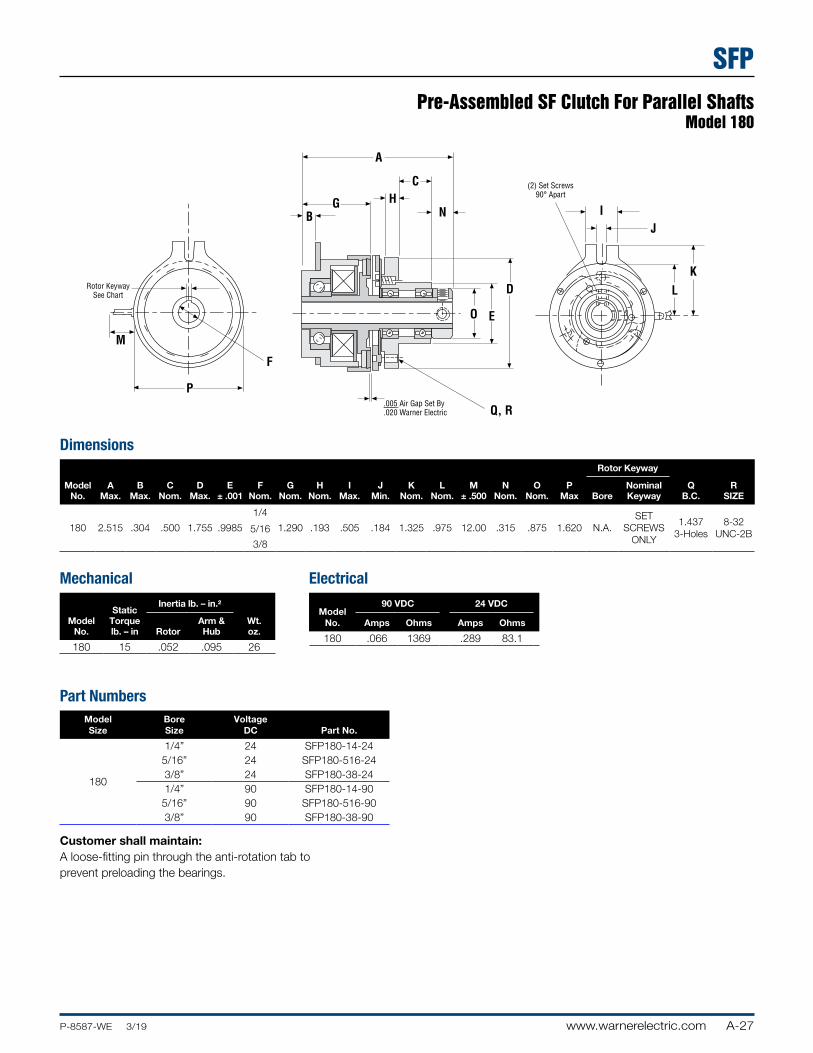
Pre-Assembled SF Clutch For Parallel ShaftsModel 180
SFP
M
P
F
Q, R
Rotor Keyway See Chart
.005 Air Gap Set By
.020 Warner Electric
I J
K
L
(2) Set Screws90° Apart
D
EO
NH
C
GB
A
Dimensions
Model No.
AMax.
BMax.
CNom.
DMax.
E± .001
FNom.
GNom.
HNom.
IMax.
JMin.
KNom.
LNom.
M± .500
NNom.
ONom.
PMax
Rotor Keyway
QB.C.
RSIZEBore
Nominal Keyway
180 2.515 .304 .500 1.755 .9985
1/4
1.290 .193 .505 .184 1.325 .975 12.00 .315 .875 1.620 N.A.SET
SCREWS ONLY
1.437 3-Holes
8-32 UNC-2B5/16
3/8
Mechanical
Model No.
Static Torque lb. – in
Inertia lb. – in.2
Wt. oz.Rotor
Arm & Hub
180 15 .052 .095 26
Electrical
Model No.
90 VDC 24 VDC
Amps Ohms Amps Ohms
180 .066 1369 .289 83.1
Part NumbersModel Size
Bore Size
Voltage DC Part No.
180
1/4” 24 SFP180-14-245/16” 24 SFP180-516-243/8” 24 SFP180-38-241/4” 90 SFP180-14-905/16” 90 SFP180-516-903/8” 90 SFP180-38-90
Customer shall maintain:A loose-fitting pin through the anti-rotation tab to prevent preloading the bearings.
A-28 www.warnerelectric.com P-8587-WE 3/19
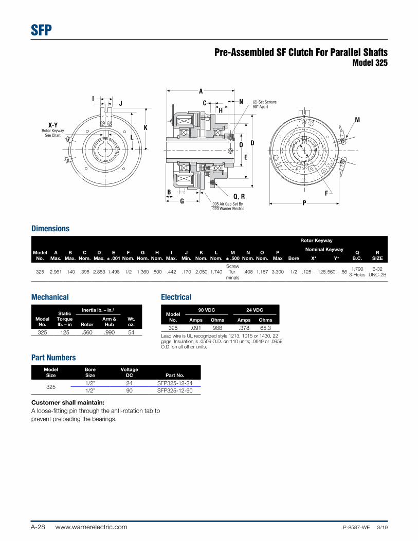
Dimensions
Model No.
AMax.
BMax.
CNom.
DMax.
E± .001
FNom.
GNom.
HNom.
IMax.
JMin.
KNom.
LNom.
M± .500
NNom.
ONom.
PMax
Rotor Keyway
QB.C.
RSIZEBore
Nominal Keyway
X* Y*
325 2.961 .140 .395 2.883 1.498 1/2 1.360 .500 .442 .170 2.050 1.740Screw Ter-
minals.408 1.187 3.300 1/2 .125 – .128.560 – .56
1.790 3-Holes
6-32 UNC-2B
Mechanical
Model No.
Static Torque lb. – in
Inertia lb. – in.2
Wt. oz.Rotor
Arm & Hub
325 125 .560 .990 54
Electrical
Model No.
90 VDC 24 VDC
Amps Ohms Amps Ohms
325 .091 988 .378 65.3Lead wire is UL recognized style 1213, 1015 or 1430, 22 gage. Insulation is .0509 O.D. on 110 units; .0649 or .0959 O.D. on all other units.
Part NumbersModel Size
Bore Size
Voltage DC Part No.
3251/2” 24 SFP325-12-241/2” 90 SFP325-12-90
Customer shall maintain:A loose-fitting pin through the anti-rotation tab to prevent preloading the bearings.
I J
L
K Rotor Keyway See Chart
.005 Air Gap Set By
.020 Warner Electric
(2) Set Screws90° Apart
Q, R
D
E
P
F
O
NH
C
GB
A
MX-Y
Pre-Assembled SF Clutch For Parallel ShaftsModel 325
SFP
SP-1www.warnerelectric.comP-8587-WE 3/19
Service Parts
SP
EC clutches• Replace clutch rotor and armature
EB brakes• Replace magnet and armature
ATC clutches• Replace clutch rotor facing and
armature facing
• Inspect splined hub
ATB brakes• Replace magnet facing and armature
facing
• Inspect splined hub
A note on burnishing:When new friction surfaces are installed it will be necessary to burnish the unit prior to returning to full production rates. Burnishing is the act of wearing in the friction faces to ensure full engagement and therefore full torque. Burnishing is achieved by simply cycling the unit under less than full load (machine empty, if possible). Most units will achieve full torque in less than 100 cycles. Refer to the service manual for more details.
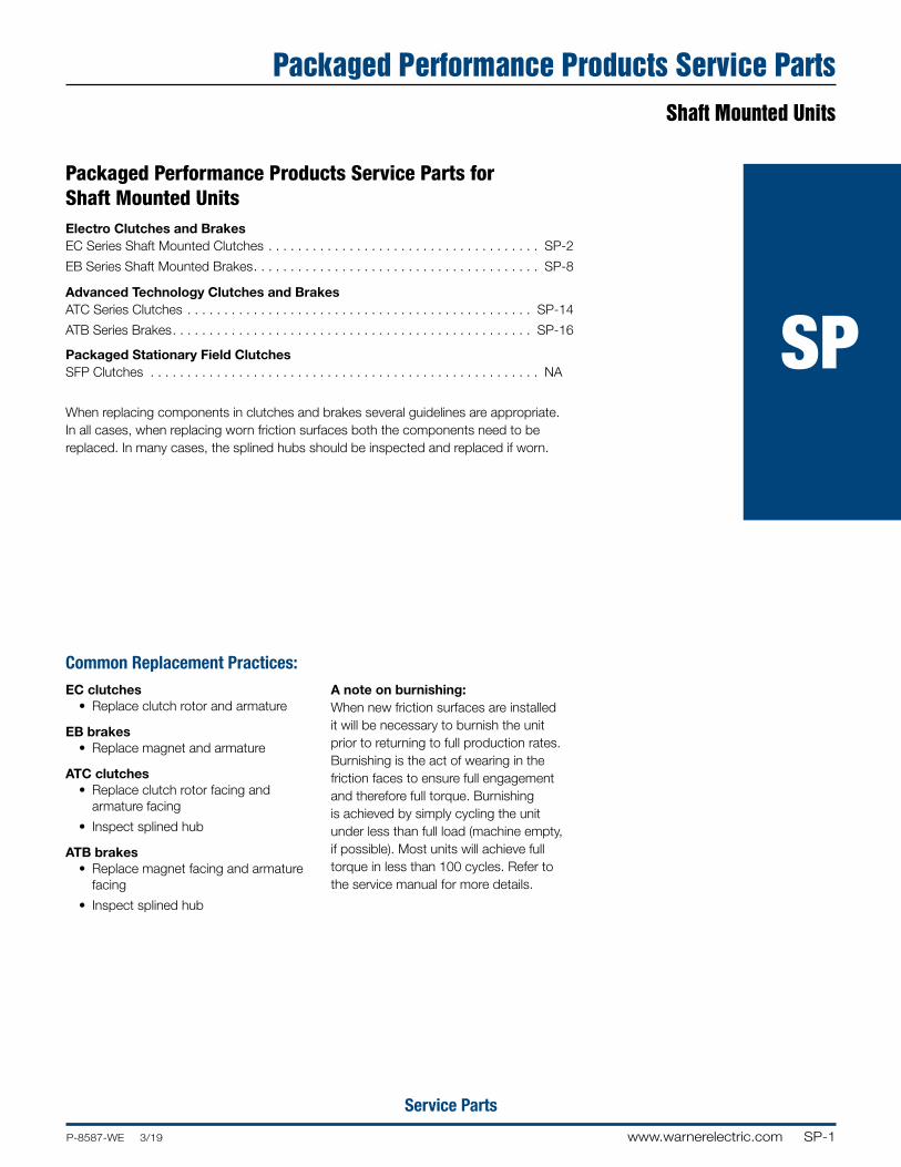
Packaged Performance Products Service Parts for Shaft Mounted UnitsElectro Clutches and BrakesEC Series Shaft Mounted Clutches . . . . . . . . . . . . . . . . . . . . . . . . . . . . . . . . . . . . . SP-2
EB Series Shaft Mounted Brakes. . . . . . . . . . . . . . . . . . . . . . . . . . . . . . . . . . . . . . . SP-8
Advanced Technology Clutches and BrakesATC Series Clutches . . . . . . . . . . . . . . . . . . . . . . . . . . . . . . . . . . . . . . . . . . . . . . . SP-14
ATB Series Brakes. . . . . . . . . . . . . . . . . . . . . . . . . . . . . . . . . . . . . . . . . . . . . . . . . SP-16
Packaged Stationary Field ClutchesSFP Clutches . . . . . . . . . . . . . . . . . . . . . . . . . . . . . . . . . . . . . . . . . . . . . . . . . . . . . NA
When replacing components in clutches and brakes several guidelines are appropriate. In all cases, when replacing worn friction surfaces both the components need to be replaced. In many cases, the splined hubs should be inspected and replaced if worn.
Common Replacement Practices:
Packaged Performance Products Service PartsShaft Mounted Units
SP-2 www.warnerelectric.com P-8587-WE 3/19
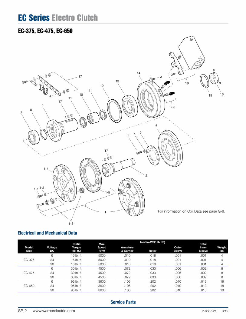
Service Parts
EC-375, 475, 650 Exploded11/5/99page 78
17
A
78
917
1110
11
1213
14A
18
15 16
14-1
6
543
17
1-4
1-21-1
1-3
1
1-5
2
ModelSize
VoltageDC
StaticTorque(lb. ft.)
Max.SpeedRPM
Inertia–WR2 (lb. ft2)TotalInner
SleeveWeight
lbs.Armature& Carrier Rotor
OuterSleeve
6 16 lb. ft. 5000 .010 .018 .001 .001 4EC-375 24 16 lb. ft. 5000 .010 .018 .001 .001 4
90 16 lb. ft. 5000 .010 .018 .001 .001 46 30 lb. ft. 4500 .072 .033 .006 .002 8
EC-475 24 30 lb. ft. 4500 .072 .033 .006 .002 890 30 lb. ft. 4500 .072 .033 .006 .002 86 95 lb. ft. 3600 .106 .202 .010 .013 18
EC-650 24 95 lb. ft. 3600 .106 .202 .010 .013 1890 95 lb. ft. 3600 .106 .202 .010 .013 18
For information on Coil Data see page G-8.
Electrical and Mechanical Data
EC-375, EC-475, EC-650
EC Series Electro Clutch

SP-3www.warnerelectric.comP-8587-WE 3/19
Service Parts
EC-375, EC-475, EC-650
EC Series Electro Clutch
Component PartsEC-375 EC-475 EC-650
Item Description Part No. Qty. Part No. Qty. Part No. Qty.
1
Armature & Carrier Assembly 5380-101-006 1 5181-101-003 1 5281-101-003 11-1 Capscrew 797-1214 3 797-1214 3 797-0086 31-2 Lockwasher 950-0102 3 950-0102 3 950-0102 31-3 Autogap Accessory 5180-101-011 3 5181-101-010 4 5181-101-010 41-4 Carrier 5380-295-002 1 5181-295-002 1 5281-295-002 11-5 Armature 5180-111-002 1 5181-111-002 1 5281-111-002 1
2
Inner Sleeve 1 1 11/2” Bore 803-00545/8” Bore 803-0055 803-10073/4” Bore 803-10057/8” Bore 803-10061” Bore 803-00471-1/8” Bore 803-00491-1/4” Bore 803-00481-3/8” Bore 803-0050
3 Screw 797-1050 6 797-1039 4 797-0083 44 Lockwasher 950-0105 6 950-0102 4 950-0103 45 Retainer Plate 748-0391 1 748-0393 1 748-0389 16 Rotor 5180-751-001 1 5181-751-003 1 5281-751-001 17 Ball Bearing 166-0149 1 166-2016 2 166-0110 18 Retainer ring 748-0017 1 748-0023 2 748-0002 19 Outer Sleeve 5180-104-001 1 803-1003 1 5281-104-001 110 Sleeve Bearing 166-0177 1 166-0179 1 166-0178 111 Oil Seal 795-0027 2 795-0028 2 795-0026 212 Retainer Ring 748-0101 1 748-0102 1 748-0104 113 Ball Bearing 166-0150 1 166-0110 1 166-0104 1
14
Field 1 1 16 volt 5180-451-002 5181-451-002 5281-451-00224 volt 5180-451-004 5181-451-004 5281-451-00490 volt 5180-451-005 5181-451-005 5281-451-00514-1 Terminal Accessory 5103-101-002 1 5103-101-002 1 5311-101-001 1
15 Retainer Ring 748-0018 1 748-0002 1 748-0004 116 Set Collar 266-0011 1 266-0012 1 266-0010 1
17
Accessory, W/Keys 1 1 11/2” Bore 5180-101-0015/8” Bore 5180-101-001 5181-101-0013/4” Bore 5181-101-0017/8” Bore 5181-101-0021” Bore 5281-101-0011-1/8” Bore 5281-101-0011-1/4” Bore 5281-101-0011-3/8” Bore 5281-101-002
18 Conduit Box 5200-101-010 1 5200-101-010 1 5200-101-010 1
Refer to service manual P-273-5-WE. These units meet the standards of UL 508 and are listed under guide card #NMTR2, file #59164.
SP-4 www.warnerelectric.com P-8587-WE 3/19
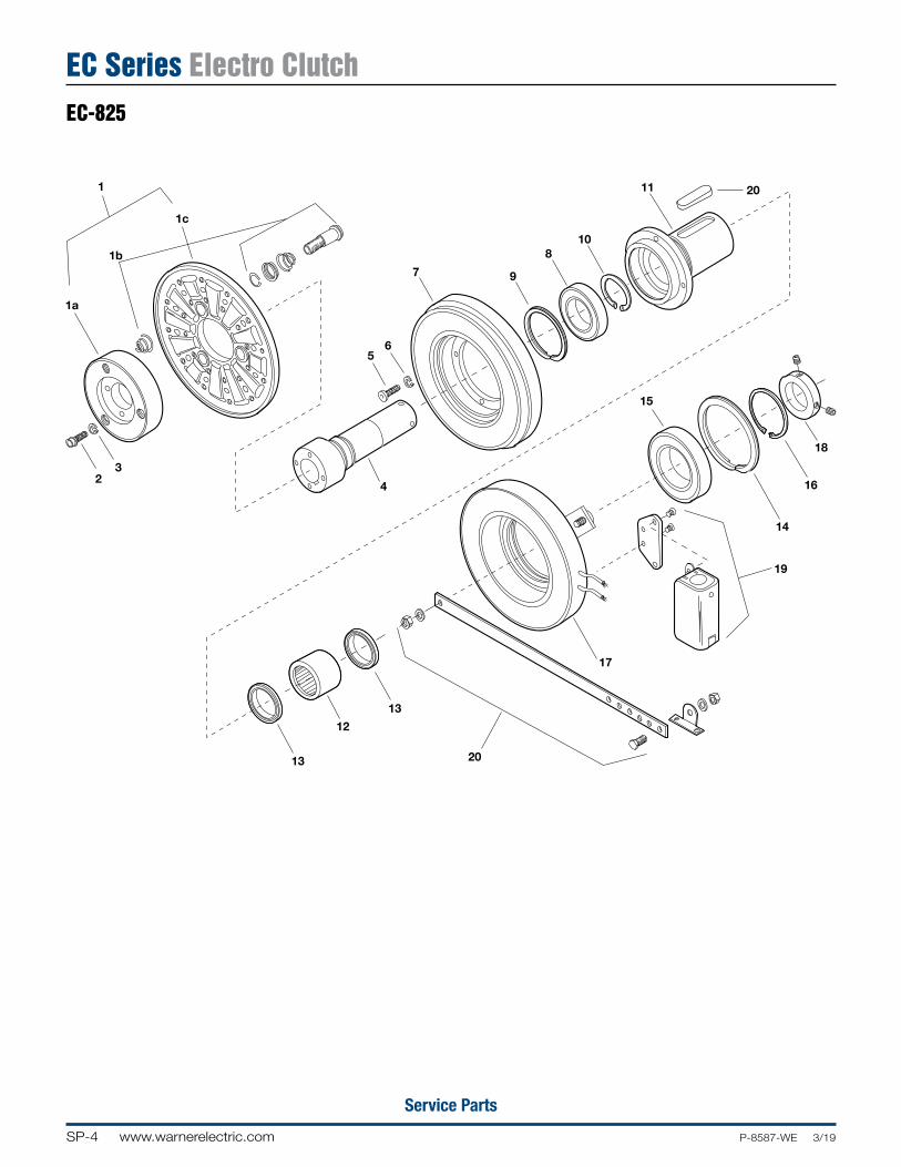
Service Parts
EC-825 Exploded11/5/99page 81
1
1c
1b
1a
32
13
12
13
20
17
19
14
16
18
4
56
7 9
810
11 20
15
EC-825
EC Series Electro Clutch
SP-5www.warnerelectric.comP-8587-WE 3/19
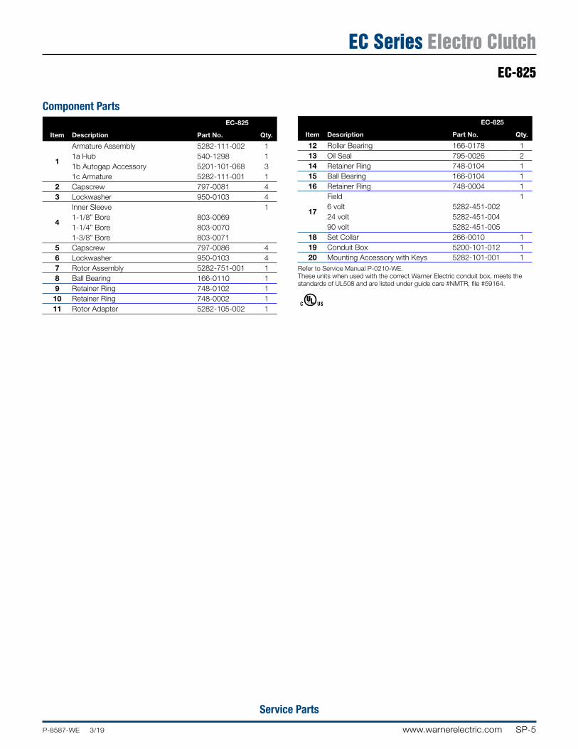
Service Parts
Component PartsEC-825
Item Description Part No. Qty.
1
Armature Assembly 5282-111-002 11a Hub 540-1298 11b Autogap Accessory 5201-101-068 31c Armature 5282-111-001 1
2 Capscrew 797-0081 43 Lockwasher 950-0103 4
4
Inner Sleeve 11-1/8” Bore 803-00691-1/4” Bore 803-00701-3/8” Bore 803-0071
5 Capscrew 797-0086 46 Lockwasher 950-0103 47 Rotor Assembly 5282-751-001 18 Ball Bearing 166-0110 19 Retainer Ring 748-0102 1
10 Retainer Ring 748-0002 111 Rotor Adapter 5282-105-002 1
EC-825
Item Description Part No. Qty.
12 Roller Bearing 166-0178 113 Oil Seal 795-0026 214 Retainer Ring 748-0104 115 Ball Bearing 166-0104 116 Retainer Ring 748-0004 1
17
Field 16 volt 5282-451-00224 volt 5282-451-00490 volt 5282-451-005
18 Set Collar 266-0010 119 Conduit Box 5200-101-012 120 Mounting Accessory with Keys 5282-101-001 1
Refer to Service Manual P-0210-WE.These units when used with the correct Warner Electric conduit box, meets the standards of UL508 and are listed under guide care #NMTR, file #59164.
EC-825
EC Series Electro Clutch
SP-6 www.warnerelectric.com P-8587-WE 3/19
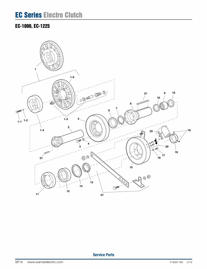
Service Parts
EC-1000, 1225 Exploded11/5/99page 84
1
1-1 1-2
1-4
21
1112
1413
21
15
1617
18
20
1922
34
2
5
67
8
21
10
9 10
1-3
1-5
EC-1000, EC-1225
EC Series Electro Clutch
SP-7www.warnerelectric.comP-8587-WE 3/19
Service Parts
EC-1000, EC-1225
EC Series Electro Clutch
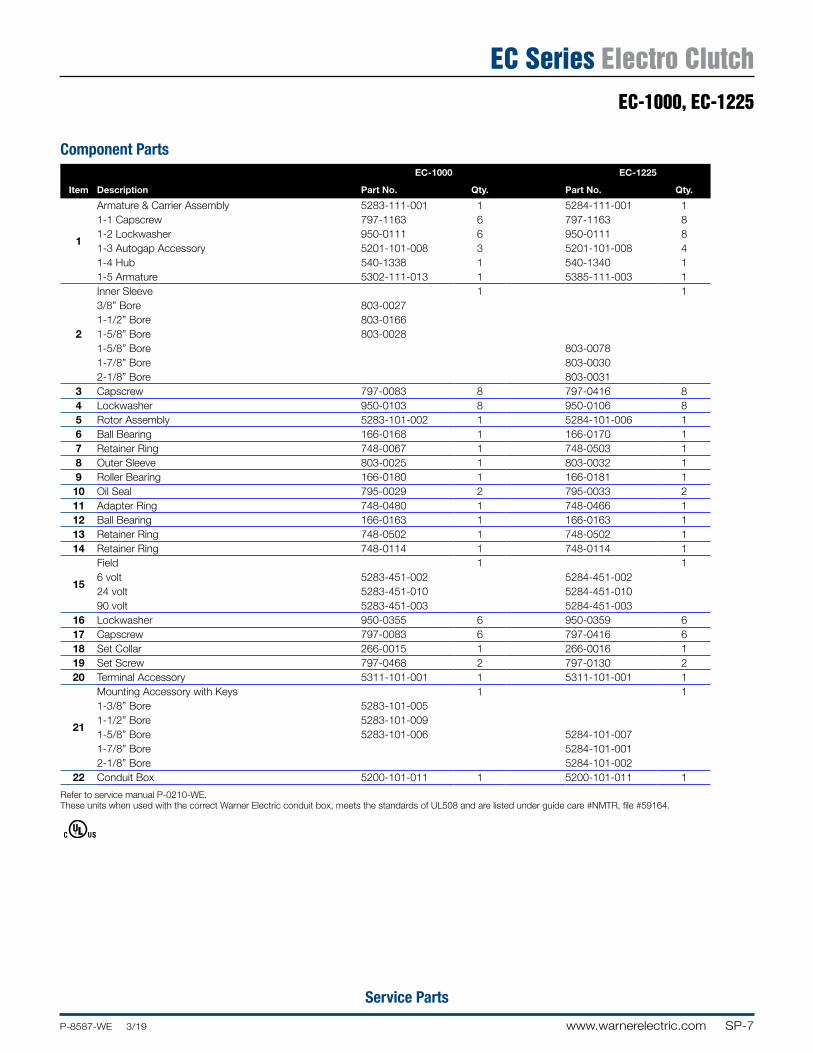
Component PartsEC-1000 EC-1225
Item Description Part No. Qty. Part No. Qty.
1
Armature & Carrier Assembly 5283-111-001 1 5284-111-001 11-1 Capscrew 797-1163 6 797-1163 81-2 Lockwasher 950-0111 6 950-0111 81-3 Autogap Accessory 5201-101-008 3 5201-101-008 41-4 Hub 540-1338 1 540-1340 11-5 Armature 5302-111-013 1 5385-111-003 1
2
Inner Sleeve 1 13/8” Bore 803-00271-1/2” Bore 803-01661-5/8” Bore 803-00281-5/8” Bore 803-00781-7/8” Bore 803-00302-1/8” Bore 803-0031
3 Capscrew 797-0083 8 797-0416 84 Lockwasher 950-0103 8 950-0106 85 Rotor Assembly 5283-101-002 1 5284-101-006 16 Ball Bearing 166-0168 1 166-0170 17 Retainer Ring 748-0067 1 748-0503 18 Outer Sleeve 803-0025 1 803-0032 19 Roller Bearing 166-0180 1 166-0181 110 Oil Seal 795-0029 2 795-0033 211 Adapter Ring 748-0480 1 748-0466 112 Ball Bearing 166-0163 1 166-0163 113 Retainer Ring 748-0502 1 748-0502 114 Retainer Ring 748-0114 1 748-0114 1
15
Field 1 16 volt 5283-451-002 5284-451-00224 volt 5283-451-010 5284-451-01090 volt 5283-451-003 5284-451-003
16 Lockwasher 950-0355 6 950-0359 617 Capscrew 797-0083 6 797-0416 618 Set Collar 266-0015 1 266-0016 119 Set Screw 797-0468 2 797-0130 220 Terminal Accessory 5311-101-001 1 5311-101-001 1
21
Mounting Accessory with Keys 1 11-3/8” Bore 5283-101-0051-1/2” Bore 5283-101-0091-5/8” Bore 5283-101-006 5284-101-0071-7/8” Bore 5284-101-0012-1/8” Bore 5284-101-002
22 Conduit Box 5200-101-011 1 5200-101-011 1
Refer to service manual P-0210-WE. These units when used with the correct Warner Electric conduit box, meets the standards of UL508 and are listed under guide care #NMTR, file #59164.
SP-8 www.warnerelectric.com P-8587-WE 3/19
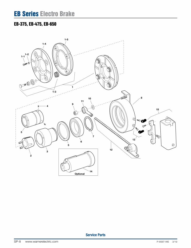
Service Parts
EB-375, 475, 650 Exploded11/7/99page 90
1-11-2
1-4
1-3
1
911
10
4
3
1-5
2
3
56
7
14Optional
12
8
15
13
EB Series Electro BrakeEB-375, EB-475, EB-650
SP-9www.warnerelectric.comP-8587-WE 3/19
Service Parts
EB-375, EB-475, EB-650
EB Series Electro Brake
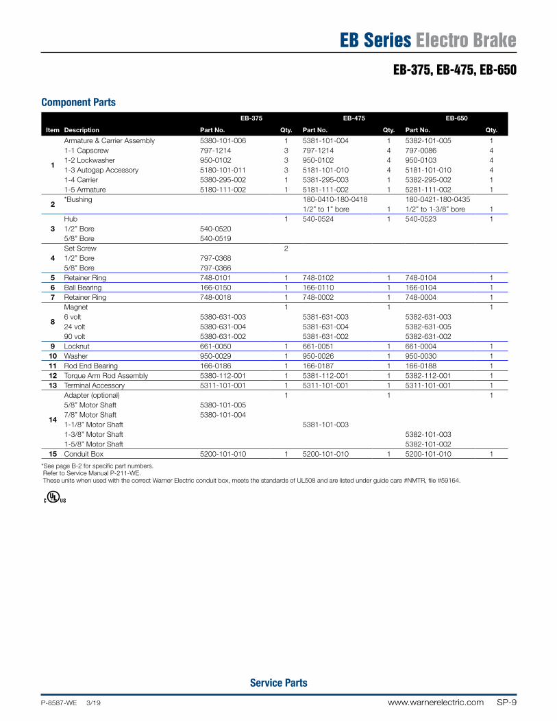
Component PartsEB-375 EB-475 EB-650
Item Description Part No. Qty. Part No. Qty. Part No. Qty.
1
Armature & Carrier Assembly 5380-101-006 1 5381-101-004 1 5382-101-005 11-1 Capscrew 797-1214 3 797-1214 4 797-0086 41-2 Lockwasher 950-0102 3 950-0102 4 950-0103 41-3 Autogap Accessory 5180-101-011 3 5181-101-010 4 5181-101-010 41-4 Carrier 5380-295-002 1 5381-295-003 1 5382-295-002 11-5 Armature 5180-111-002 1 5181-111-002 1 5281-111-002 1
2*Bushing 180-0410-180-0418 180-0421-180-0435
1/2” to 1” bore 1 1/2” to 1-3/8” bore 1
3Hub 1 540-0524 1 540-0523 11/2” Bore 540-05205/8” Bore 540-0519
4Set Screw 21/2” Bore 797-03685/8” Bore 797-0366
5 Retainer Ring 748-0101 1 748-0102 1 748-0104 16 Ball Bearing 166-0150 1 166-0110 1 166-0104 17 Retainer Ring 748-0018 1 748-0002 1 748-0004 1
8
Magnet 1 1 16 volt 5380-631-003 5381-631-003 5382-631-00324 volt 5380-631-004 5381-631-004 5382-631-00590 volt 5380-631-002 5381-631-002 5382-631-002
9 Locknut 661-0050 1 661-0051 1 661-0004 110 Washer 950-0029 1 950-0026 1 950-0030 111 Rod End Bearing 166-0186 1 166-0187 1 166-0188 112 Torque Arm Rod Assembly 5380-112-001 1 5381-112-001 1 5382-112-001 113 Terminal Accessory 5311-101-001 1 5311-101-001 1 5311-101-001 1
14
Adapter (optional) 1 1 15/8” Motor Shaft 5380-101-0057/8” Motor Shaft 5380-101-0041-1/8” Motor Shaft 5381-101-0031-3/8” Motor Shaft 5382-101-0031-5/8” Motor Shaft 5382-101-002
15 Conduit Box 5200-101-010 1 5200-101-010 1 5200-101-010 1
*See page B-2 for specific part numbers. Refer to Service Manual P-211-WE. These units when used with the correct Warner Electric conduit box, meets the standards of UL508 and are listed under guide care #NMTR, file #59164.
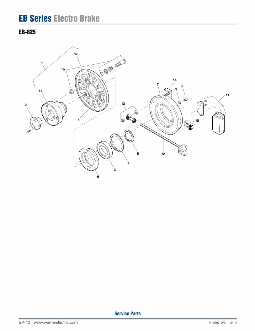
SP-10 www.warnerelectric.com P-8587-WE 3/19
Service Parts
EB-825 Exploded11/7/99page 93
1
1c
1b
2
1a
1
13
6
3
4
5 12
79
8
10
11
14
EB-825
EB Series Electro Brake
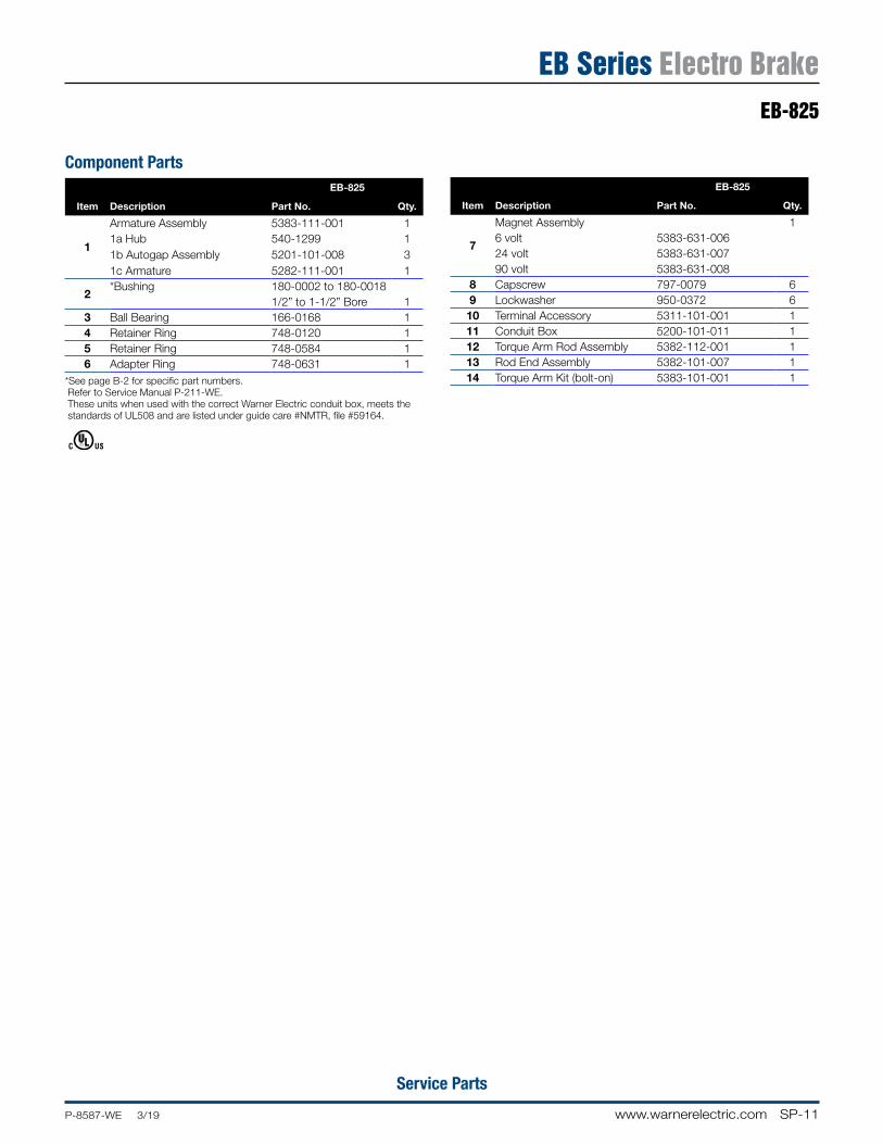
SP-11www.warnerelectric.comP-8587-WE 3/19
Service Parts
EB-825
EB Series Electro Brake
Component PartsEB-825
Item Description Part No. Qty.
1
Armature Assembly 5383-111-001 11a Hub 540-1299 11b Autogap Assembly 5201-101-008 31c Armature 5282-111-001 1
2*Bushing 180-0002 to 180-0018
1/2” to 1-1/2” Bore 13 Ball Bearing 166-0168 14 Retainer Ring 748-0120 15 Retainer Ring 748-0584 16 Adapter Ring 748-0631 1
*See page B-2 for specific part numbers. Refer to Service Manual P-211-WE. These units when used with the correct Warner Electric conduit box, meets the standards of UL508 and are listed under guide care #NMTR, file #59164.
EB-825
Item Description Part No. Qty.
7
Magnet Assembly 16 volt 5383-631-00624 volt 5383-631-00790 volt 5383-631-008
8 Capscrew 797-0079 69 Lockwasher 950-0372 610 Terminal Accessory 5311-101-001 111 Conduit Box 5200-101-011 112 Torque Arm Rod Assembly 5382-112-001 113 Rod End Assembly 5382-101-007 114 Torque Arm Kit (bolt-on) 5383-101-001 1

SP-12 www.warnerelectric.com P-8587-WE 3/19
Service Parts
EB-100, 1225 Exploded11/10/99page 96
14
Optional
1-1 1-2
1-4
1-52
3
1-3
1
13-4 13-3
8
12-1
74
5 6
12-312-2
12
12-1
12-312-2
12-4
11
15
910
13-1
13-2
12-212-3
12-5
13
EB-1000, EB-1225
EB Series Electro Brake
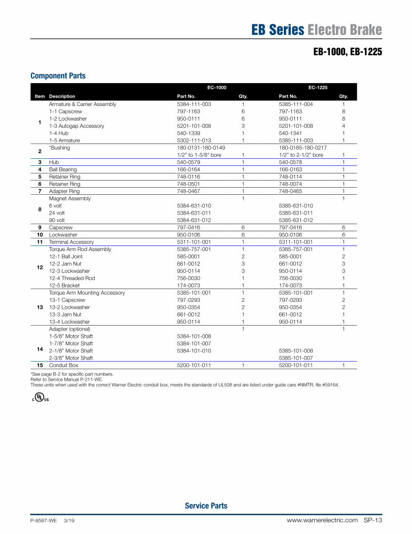
SP-13www.warnerelectric.comP-8587-WE 3/19
Service Parts
EB-1000, EB-1225
EB Series Electro Brake
Component PartsEC-1000 EC-1225
Item Description Part No. Qty. Part No. Qty.
1
Armature & Carrier Assembly 5384-111-003 1 5385-111-004 11-1 Capscrew 797-1163 6 797-1163 81-2 Lockwasher 950-0111 6 950-0111 81-3 Autogap Accessory 5201-101-008 3 5201-101-008 41-4 Hub 540-1339 1 540-1341 11-5 Armature 5302-111-013 1 5385-111-003 1
2*Bushing 180-0131-180-0149 180-0185-180-0217
1/2” to 1-5/8” bore 1 1/2” to 2-1/2” bore 13 Hub 540-0579 1 540-0578 14 Ball Bearing 166-0164 1 166-0163 15 Retainer Ring 748-0116 1 748-0114 16 Retainer Ring 748-0501 1 748-0074 17 Adapter Ring 748-0467 1 748-0465 1
8
Magnet Assembly 1 16 volt 5384-631-010 5385-631-01024 volt 5384-631-011 5385-631-01190 volt 5384-631-012 5385-631-012
9 Capscrew 797-0416 6 797-0416 610 Lockwasher 950-0106 6 950-0106 611 Terminal Accessory 5311-101-001 1 5311-101-001 1
12
Torque Arm Rod Assembly 5385-757-001 1 5385-757-001 112-1 Ball Joint 585-0001 2 585-0001 212-2 Jam Nut 661-0012 3 661-0012 312-3 Lockwasher 950-0114 3 950-0114 312-4 Threaded Rod 756-0030 1 756-0030 112-5 Bracket 174-0073 1 174-0073 1
13
Torque Arm Mounting Accessory 5385-101-001 1 5385-101-001 113-1 Capscrew 797-0293 2 797-0293 213-2 Lockwasher 950-0354 2 950-0354 213-3 Jam Nut 661-0012 1 661-0012 113-4 Lockwasher 950-0114 1 950-0114 1
14
Adapter (optional) 1 11-5/8” Motor Shaft 5384-101-0081-7/8” Motor Shaft 5384-101-0072-1/8” Motor Shaft 5384-101-010 5385-101-0082-3/8” Motor Shaft 5385-101-007
15 Conduit Box 5200-101-011 1 5200-101-011 1
*See page B-2 for specific part numbers. Refer to Service Manual P-211-WE. These units when used with the correct Warner Electric conduit box, meets the standards of UL508 and are listed under guide care #NMTR, file #59164.
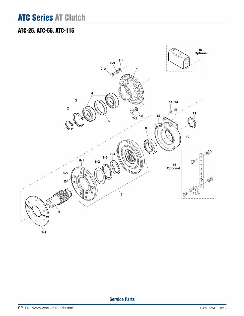
SP-14 www.warnerelectric.com P-8587-WE 3/19
Service Parts
ATC-25, 55, 115 Exploded
2
3
9
12
14
15
13
11
16
7-1
6
10
8-1
8
Optional
Optional
5
4
7-37-2
7-2
7-37-4
1
8-2
8-48-3
8-5
ATC Series AT ClutchATC-25, ATC-55, ATC-115
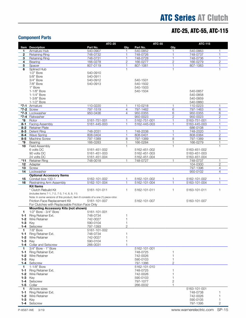
SP-15www.warnerelectric.comP-8587-WE 3/19
Service Parts
ATC Series AT ClutchATC-25, ATC-55, ATC-115
Component PartsATC-25 ATC-55 ATC-115
Item Description Part No. Qty. Part No. Qty.1 Armature Hub 540-0907 1 540-0852 1 540-0863 12 Retaining Ring 748-0732 1 748-0726 1 748-0737 13 Retaining Ring 748-0731 1 748-0728 1 748-0736 14 Bearing 166-0278 2 166-0277 2 166-0279 25 Spacer 807-0119 1 807-1061 1 807-1063 16 Splined Hub 1 1 1
1/2” Bore 540-09105/8” Bore 540-09113/4” Bore 540-0912 540-15017/8” Bore 540-0913 540-15021” Bore 540-15031-1/8” Bore 540-1504 540-08571-1/4” Bore 540-08581-3/8” Bore 540-08591-1/2” Bore 540-0860
*7-1 Armature 110-0220 1 110-0218 1 110-0223 1*7-2 Screw 797-1519 4 797-1462 6 797-1463 6*7-3 Lockwasher 950-0436 4 950-0355 6 950-0355 6*7-4 Flatwasher 950-0023 2 950-0023 2*8 Rotor 5161-751-001 1 5162-751-001 1 5163-751-001 18-1 Facing Assembly 5161-445-003 1 5162-445-003 1 5163-445-003 18-2 Retainer Plate 686-0108 18-3 Detent Ring 748-2031 1 748-2038 1 748-2020 18-4 Wave Spring 808-0404 1 808-0401 1 808-0384 28-5 Machine Screw 797-1389 8 797-1389 8 797-1389 8*9 Bearing 166-0283 1 166-0284 1 166-0279 110 Field Assembly 1 1 1
6 volts DC 5161-451-002 5162-451-002 5163-451-00290 volts DC 5161-451-003 5162-451-003 5163-451-00324 volts DC 5161-451-004 5162-451-004 5163-451-004
*11 Retainer Ring 748-0018 1 748-0727 1 748-0737 112 Adapter 104-0300 213 Screw 797-1396 414 Lockwasher 950-0102 4
Optional Accessory Items15 Conduit box 100-1 5162-101-002 1 5162-101-002 1 5162-101-002 116 Restraining Arm Assembly 5162-101-004 1 5162-101-004 1 5163-101-004 1
Kit Items* Clutch Rebuild Kit 5161-101-011 1 5162-101-011 1 5163-101-011 1(includes items 7-1, 7-2, 7-3, 7-4, 8, 9, 11)Note: In some versions of this product, item 8 consists of a one (1) piece rotor.
Friction Face Replacement Kit 5161-101-007 5162-101-007 5163-101-007For Clutches with Replaceable Friction Face OnlyMounting Accessory Kits (not shown)
1 1/2” Bore - 3/4” Bore 5161-101-0011-1 Ring Retainer Ext. 748-0734 11-2 Wire Retainer 742-0027 11-3 Key 590-0104 11-4 Setscrew 797-1393 21 7/8” Bore 5161-101-002
1-1 Ring Retainer Ext. 748-0734 11-2 Wire Retainer 742-0027 11-3 Key 590-0104 11-4 Collar and Setscrew 266-0031 11 3/4” Bore - 1” Bore 5162-101-001
1-1 Ring Retainer Ext. 748-0725 11-2 Wire Retainer 742-0026 11-3 Key 590-0103 11-4 Setscrew 797-1386 21 1-1/8” Bore 5162-101-010
1-1 Ring Retainer Ext. 748-0725 11-2 Wire Retainer 742-0026 11-3 Key 590-0103 11-4 Setscrew 797-1077 21-5 Collar 266-0032 11 All bore sizes 5163-101-001
1-1 Ring Retainer Ext. 748-0738 11-2 Wire Retainer 742-0026 11-3 Key 590-0105 11-4 Setscrew 797-1395 2
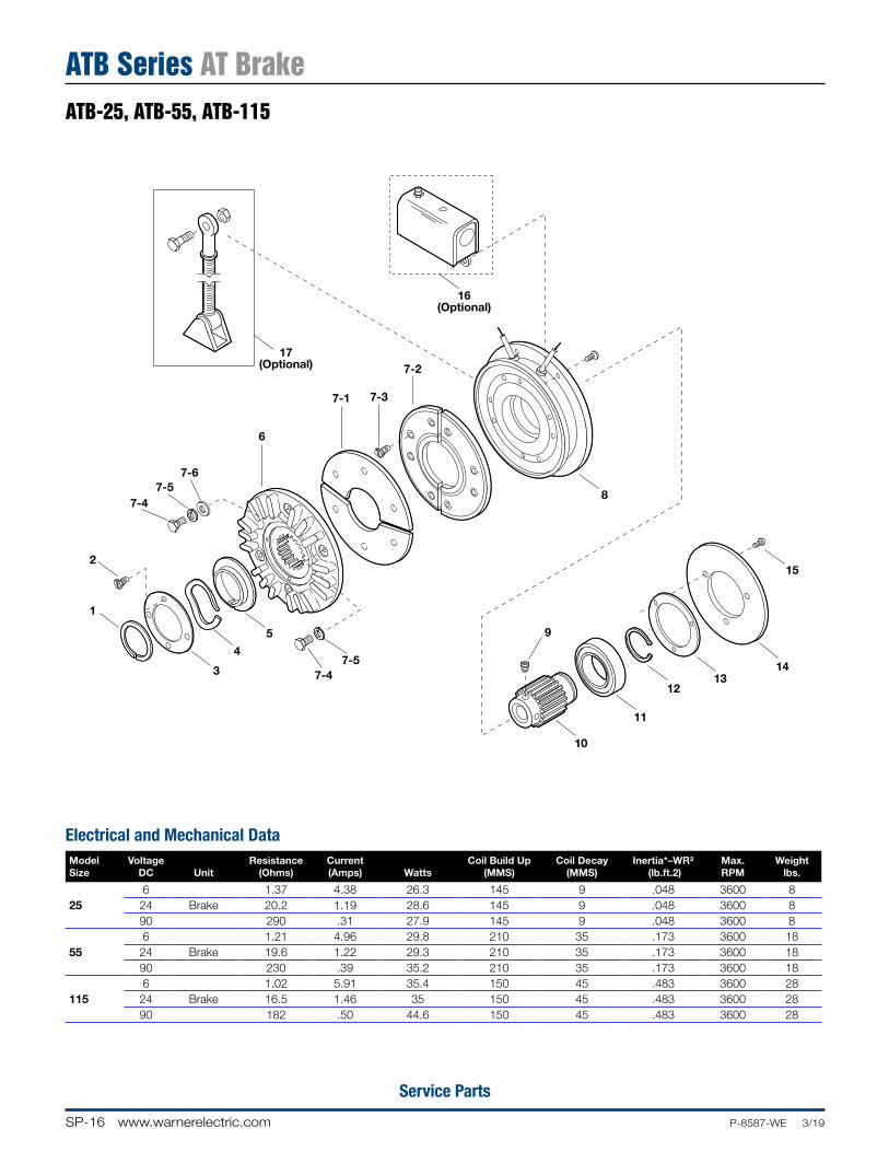
SP-16 www.warnerelectric.com P-8587-WE 3/19
Service Parts
Electrical and Mechanical DataModelSize
VoltageDC Unit
Resistance(Ohms)
Current(Amps) Watts
Coil Build Up(MMS)
Coil Decay(MMS)
Inertia*–WR2 (lb.ft.2)
Max. RPM
Weightlbs.
256 1.37 4.38 26.3 145 9 .048 3600 8
24 Brake 20.2 1.19 28.6 145 9 .048 3600 890 290 .31 27.9 145 9 .048 3600 8
556 1.21 4.96 29.8 210 35 .173 3600 18
24 Brake 19.6 1.22 29.3 210 35 .173 3600 1890 230 .39 35.2 210 35 .173 3600 18
1156 1.02 5.91 35.4 150 45 .483 3600 28
24 Brake 16.5 1.46 35 150 45 .483 3600 2890 182 .50 44.6 150 45 .483 3600 28
ATB-25, 55, 115 ExplodedDate 11/11/99page 110
17(Optional)
16(Optional)
2
1
3
4
5
7-47-5
7-47-5
7-6
6
7-1 7-3
7-2
8
9
10
11
1213
14
15
ATB-25, ATB-55, ATB-115
ATB Series AT Brake

SP-17www.warnerelectric.comP-8587-WE 3/19
Service Parts
ATB-25, ATB-55, ATB-115
ATB Series AT Brake
Component PartsATB-25 ATB-55 ATB-115
Item Description Part No. Qty. Part No. Qty. Part No. Qty.
†1 Retainer 748-0018 1 748-0727 1 748-0737 1†2 Screw 797-0321 3 797-0321 4 797-0321 43 Plate 686-0166 1 686-0162 1 686-0171 1
†4 Wave Spring 808-0404 1 808-0401 1 808-0384 2†5 Detent Ring 748-2031 1 748-2038 1 748-2020 16 Armature Hub 540-0908 1 540-0851 1 540-0864 1
*†7-1 Armature 110-0220 1 110-0218 1 110-0223 1*†7-2 Facing Assembly 5161-445-003 1 5162-445-003 1 5163-445-003 1*†7-3 Screw 797-1389 6 797-1389 8 797-1389 8*†7-4 Screw 797-1519 4 797-1462 6 797-1463 6*†7-5 Lockwasher 950-0436 4 950-0355 4 950-0355 6*†7-6 Flatwasher 950-0023 2 950-0023 2
8
Magnet Assembly 1 1 16 volts DC 5191-631-002 5192-631-002 5193-631-00224 volts DC 5191-631-004 5192-631-004 5193-631-00490 volts DC 5191-631-003 5192-631-003 5193-631-003
†9 Setscrew 797-1393 2 797-1386 2 797-1395 2
10
Splined Hub 1 1 11/2” Bore 540-09015/8” Bore 540-09023/4” Bore 540-0903 540-15127/8” Bore 540-0904 540-15131” Bore 540-15141-1/8” Bore 540-1515 540-08661-1/4” Bore 540-08671-3/8” Bore 540-0868 1-1/2” Bore 540-0869
†11 Ball Bearing 166-0283 1 166-0277 1 166-0279 1†12 Retainer Ring 748-0018 1 748-0726 1 748-0737 113 Shim 801-1035 1 801-1034 1 801-1036 114 Backplate 686-0167 1 686-0163 1 686-0172 1
†15 Screw 797-1392 4 797-0437 3 797-0447 3Optional Accessory Items
16 Conduit box 5162-101-002 1 5162-101-002 1 5162-101-002 117 Torque Arm 5191-101-001 1 5192-101-001 1 5193-101-001 1
Kit Items
*18Friction Face Replacement Kit 5161-101-007 1 5162-101-007 1 5163-101-007 1(includes items 7-1, 7-2, 7-3, 7-4, 7-5, 7-6)
†19Brake Rebuild Kit 5191-101-006 1 5192-101-006 1 5193-101-006 1(includes items, 1, 2, 4, 5, 7-1, 7-2, 7-3, 7-4, 7-5, 7-6, 9, 11, 12, 15)
Refer to Service Manual P-0218-WE.

Notes
SP-18 www.warnerelectric.com P-8587-WE 3/19

Notes
SP-19www.warnerelectric.comP-8587-WE 3/19

Notes
SP-20 www.warnerelectric.com P-8587-WE 3/19

G-1General Engineering Data 3/19 www.warnerelectric.com
General Engineering Data G
G-2 www.warnerelectric.com General Engineering Data 3/19
Mechanical Data Application Engineering
Ordering Information / Standard NEMA Frame Dimensions ............................. G-3
Mechanical Data / Dynamic Torque .................................................................... G-4
Mechanical Data / Rotational Speed ................................................................... G-6
Mechanical Data / Clutch Field Restraining Devices ......................................... G-7
Electrical Data / Coil Ratings .............................................................................. G-8
Electrical Data / Installation Procedure ............................................................ G-11
Electrical Data / Coil Suppression & Clutch/Brake Overlap ........................... G-12
Electrical Data / Overexcitation ......................................................................... G-13
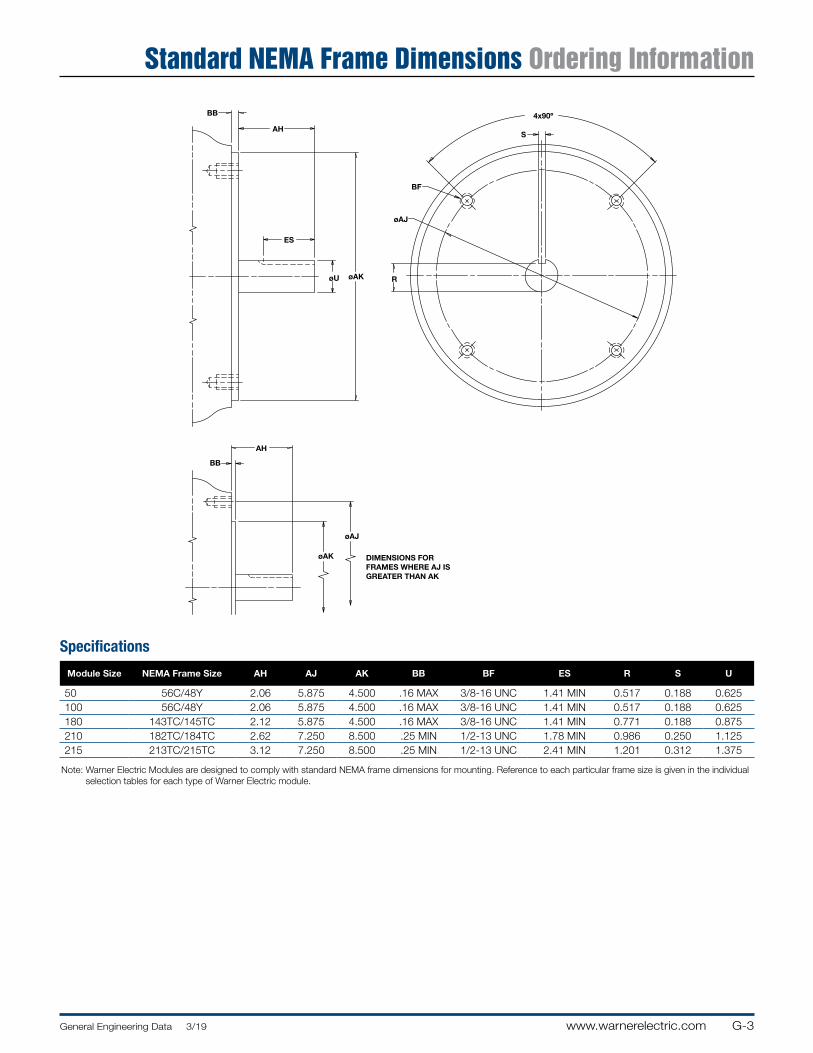
G-3General Engineering Data 3/19 www.warnerelectric.com
Standard NEMA Frame Dimensions Ordering Information
BB
AH
ES
øU
BF
øAJ
S
4x90º
AH
øAJ
øAK
BB
R
DIMENSIONS FORFRAMES WHERE AJ ISGREATER THAN AK
øAK
Specifications
Module Size NEMA Frame Size AH AJ AK BB BF ES R S U
50 56C/48Y 2.06 5.875 4.500 .16 MAX 3/8-16 UNC 1.41 MIN 0.517 0.188 0.625100 56C/48Y 2.06 5.875 4.500 .16 MAX 3/8-16 UNC 1.41 MIN 0.517 0.188 0.625180 143TC/145TC 2.12 5.875 4.500 .16 MAX 3/8-16 UNC 1.41 MIN 0.771 0.188 0.875210 182TC/184TC 2.62 7.250 8.500 .25 MIN 1/2-13 UNC 1.78 MIN 0.986 0.250 1.125215 213TC/215TC 3.12 7.250 8.500 .25 MIN 1/2-13 UNC 2.41 MIN 1.201 0.312 1.375
Note: Warner Electric Modules are designed to comply with standard NEMA frame dimensions for mounting. Reference to each particular frame size is given in the individual selection tables for each type of Warner Electric module.
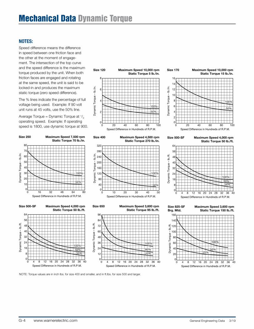
G-4 www.warnerelectric.com General Engineering Data 3/19
Mechanical Data Dynamic Torque
NOTES:Speed difference means the difference in speed between one friction face and the other at the moment of en gage-ment. The intersection of the top curve and the speed difference is the maximum torque produced by the unit. When both friction faces are engaged and rotating at the same speed, the unit is said to be locked-in and produces the maximum static torque (zero speed difference).
The % lines indicate the percentage of full voltage being used. Example: If 90 volt unit runs at 45 volts, use the 50% line.
Average Torque = Dynamic Torque at 1/2
operating speed. Example: If operating speed is 1800, use dynamic torque at 900.
100%
50%
8
6
4
2
00 20 40 60 80 100
Speed Difference in Hundreds of R.P.M.
Dyn
amic
Tor
que
– lb
./in
.
Size 120 Maximum Speed 10,000 rpmStatic Torque 5 lb./in.
100%
50%
16
14
12
10
8
6
4
2
00 20 40 60 80 100
Speed Difference in Hundreds of R.P.M.
Dyn
amic
Tor
que
– lb
./in
.
Size 170 Maximum Speed 10,000 rpmStatic Torque 15 lb./in.
100%
50%
0 16 32 48 64 80
Speed Difference in Hundreds of R.P.M.
Dyn
amic
Tor
que
– lb
./in
.
Size 250 Maximum Speed 7,500 rpmStatic Torque 70 lb./in.
80
70
60
50
40
30
20
10
0
100%
50%
0 10 20 30 40 50
Speed Difference in Hundreds of R.P.M.
Dyn
amic
Tor
que
– lb
./in
.
Size 400 Maximum Speed 4,500 rpmStatic Torque 270 lb./in.
320
280
240
200
160
120
80
40
0
100%
50%35%
64
56
48
40
32
24
16
8
00 4 8 12 16 20 24 28 32 36 40
Speed Difference in Hundreds of R.P.M.
Dyn
amic
Tor
que
– lb
./ft
.
Size 500-SF Maximum Speed 4,000 rpmStatic Torque 50 lb./ft.
100%
50%35%
64
56
48
40
32
24
16
8
00 4 8 12 16 20 24 28 32 36 40
Speed Difference in Hundreds of R.P.M.
Dyn
amic
Tor
que
– lb
./ft
.
Size 500-SF Maximum Speed 4,000 rpmStatic Torque 50 lb./ft.
100%
60%
25%
0 4 8 12 16 20 24 28 32 36 40
Speed Difference in Hundreds of R.P.M.
Dyn
amic
Tor
que
– lb
./ft
.
Size 650 Maximum Speed 3,600 rpmStatic Torque 95 lb./ft.
96
84
72
60
48
36
24
12
0
100%
50%25%
160
140
120
100
80
60
40
20
00 4 8 12 16 20 24 28 32 36 40
Speed Difference in Hundreds of R.P.M.
Dyn
amic
Tor
que
– lb
./ft
.
Size 825-SFBrg. Mtd.
Maximum Speed 3,600 rpmStatic Torque 150 lb./ft.
NOTE: Torque values are in inch lbs. for size 400 and smaller, and in ft.lbs. for size 500 and larger.
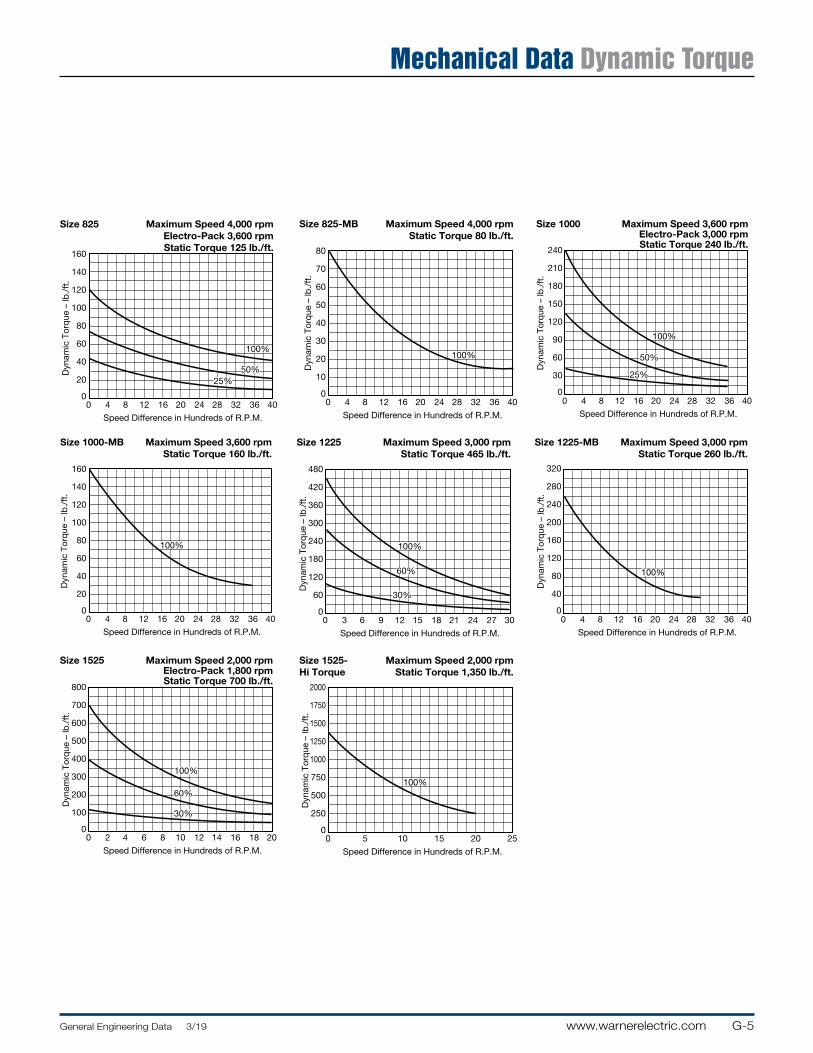
G-5General Engineering Data 3/19 www.warnerelectric.com
Mechanical Data Dynamic Torque
100%
25%50%
0 4 8 12 16 20 24 28 32 36 40
Speed Difference in Hundreds of R.P.M.
Dyn
amic
Tor
que
– lb
./ft
.
Size 825 Maximum Speed 4,000 rpmElectro-Pack 3,600 rpmStatic Torque 125 lb./ft.
160
140
120
100
80
60
40
20
0
100%
0 4 8 12 16 20 24 28 32 36 40
Speed Difference in Hundreds of R.P.M.
Dyn
amic
Tor
que
– lb
./ft
.
Size 825-MB Maximum Speed 4,000 rpmStatic Torque 80 lb./ft.
80
70
60
50
40
30
20
10
0
100%
50%
25%
240
210
180
150
120
90
60
30
00 4 8 12 16 20 24 28 32 36 40
Speed Difference in Hundreds of R.P.M.
Dyn
amic
Tor
que
– lb
./ft
.
Size 1000 Maximum Speed 3,600 rpmElectro-Pack 3,000 rpmStatic Torque 240 lb./ft.
100%
0 4 8 12 16 20 24 28 32 36 40
160
140
120
100
80
60
40
20
0
Speed Difference in Hundreds of R.P.M.
Dyn
amic
Tor
que
– lb
./ft
.
Size 1000-MB Maximum Speed 3,600 rpmStatic Torque 160 lb./ft.
100%
60%
30%
0 3 6 9 12 15 18 21 24 27 30
Speed Difference in Hundreds of R.P.M.
Dyn
amic
Tor
que
– lb
./ft
.
Size 1225 Maximum Speed 3,000 rpmStatic Torque 465 lb./ft.
480
420
360
300
240
180
120
60
0
100%
320
280
240
200
160
120
80
40
00 4 8 12 16 20 24 28 32 36 40
Speed Difference in Hundreds of R.P.M.
Dyn
amic
Tor
que
– lb
./ft
.
Size 1225-MB Maximum Speed 3,000 rpmStatic Torque 260 lb./ft.
100%
30%
60%
0 2 4 6 8 10 12 14 16 18 20
Speed Difference in Hundreds of R.P.M.
Dyn
amic
Tor
que
– lb
./ft
.
Size 1525 Maximum Speed 2,000 rpmElectro-Pack 1,800 rpmStatic Torque 700 lb./ft.
800
700
600
500
400
300
200
100
0
100%
0 5 10 15 20 25
Speed Difference in Hundreds of R.P.M.
Dyn
amic
Tor
que
– lb
./ft
.
Size 1525-Hi Torque
Maximum Speed 2,000 rpmStatic Torque 1,350 lb./ft.
2000
1750
1500
1250
1000
750
500
250
0
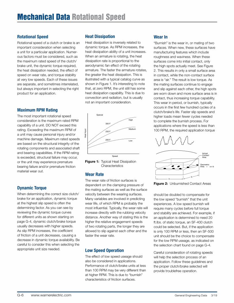
G-6 www.warnerelectric.com General Engineering Data 3/19
Mechanical Data Rotational Speed
Rotational SpeedRotational speed of a clutch or brake is an im por tant con sid er ation when selecting a unit for a particular ap pli ca tion. Nu mer-ous factors must be con sid ered, such as the maximum rated speed of the clutch/brake unit, the dynamic torque required, the heat dissipation needed, the effect of speed on wear rate, and torque stability at very low speeds. Each of these issues are separate, and sometimes interrelated, but always important in selecting the right product for an application.
Maximum RPM RatingThe most important rotational speed consideration is the maximum rated RPM capability of a unit. DO NOT exceed this rating. Exceeding the maximum RPM of a unit may cause personal injury and/or machine damage. Maximum rated speeds are based on the structural integrity of the rotating components and associated shaft and bearing capabilities. If the RPM rating is exceeded, struc tur al failure may occur, or the unit may experience premature bearing failure and/or pre ma ture friction material wear out.
Dynamic TorqueWhen determining the correct size clutch/brake for an ap pli ca tion, dynamic torque at the highest slip speed is often the determining factor. As you can see by reviewing the dynamic torque curves for different units as shown starting on page G-4, dynamic clutch/brake torque usually decreases with higher speeds. As slip RPM increases, the co ef fi cient of friction of a unit de creas es, causing a decrease in dynamic torque avail abil i ty. Be careful to consider this when selecting the appropriate unit size needed.
Wear RateThe wear rate of friction surfaces is dependent on the clamping pressure of the mating surfaces as well as the surface velocity between the wearing surfaces. Many variables are involved in predicting wear life, of which RPM is probably the most influential. Typically, the wear rate will increase directly with the rubbing velocity distance. Another way of stating this is the higher the relative engagement speeds of two rotating parts, the longer they are allowed to slip against each other and the faster the wear rate.
Special
High
Medium
Low
Speed
Figure 1
Typical Heat Dissipation Characteristics
300 F
250 F
200 F
Hea
t In
put
Heat DissipationHeat dissipation is inversely related to dynamic torque. As RPM increases, the heat dissipation ability of a unit in creas es. When an armature is rotating, the heat dis si pa tion rate is proportional to the aero dy nam ic fan effect of the rotating armature. The faster the armature rotates, the greater the heat dissipation. This is illustrated with a typical catalog curve as shown in Figure 1. It’s interesting to note that, at zero RPM, the unit still has some heat dissipation capability. This is due to convection and radiation, but is usually not an important consideration.
Low Speed OperationThe effect of low speed useage should also be considered in applications. Performance of clutch/brake units at less than 100 RPM may be very different than at higher RPM. This is due to “bur nish” characteristics of friction sur fac es.
Figure 2: Unburnished Contact Areas
Wear In“Burnish” is the wear in, or mating of two surfaces. When new, these surfaces have manufacturing features which include roughness and waviness. When these surfaces come into initial contact, only the high spots actually meet. See Figure 2. This results in only a small surface area in contact, while the non-contact surface area is “air.” The result is low torque. As the mating surfaces continue to engage and slip against each other, the high spots are worn down and more surface area is in contact, thus increasing torque ca pa bil i ty. This wear in period, or burnish, typically occurs in the first few hundred cycles of a clutch/brake’s life. Faster slip speeds and higher loads mean fewer cycles needed to complete the burnish process. For applications where the speed is less than 100 RPM, the required application torque
should be doubled to compensate for the low speed “burnish” that the unit experiences. A low speed burnish will require many cycles before full torque and stability are achieved. For example, if an application is determined to need 20 ft.lbs. of static torque, an SF-400 clutch could be selected. But, if the application is only 100 RPM or less, then an SF-500 unit should be the choice to com pen sate for the low RPM useage, as indicated on the selection chart found on page G-4.
Careful consideration of rotating speeds will help the selection process of an application. Follow these guide lines and the proper clutch/brake selected will provide troublefree operation.
ab
ActualContactArea
GeometricArea = a x b
ab
ActualContactArea
GeometricArea = a x b
Figure 1: Typical Heat Dissipation Characteristics
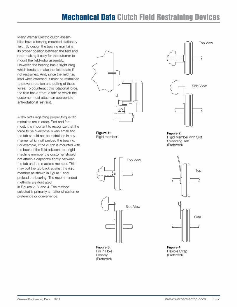
G-7General Engineering Data 3/19 www.warnerelectric.com
Mechanical Data Clutch Field Restraining Devices
Many Warner Electric clutch as sem-blies have a bearing mounted stationery field. By design the bearing maintains its proper position between the field and rotor making it easy for the cutomer to mount the field-rotor assembly. How ev er, the bearing has a slight drag which tends to make the field rotate if not restrained. And, since the field has lead wires at tached, it must be restrained to prevent rotation and pulling of these wires. To counteract this rotational force, the field has a “torque tab” to which the customer must attach an appropriate anti-rotational restraint.
A few hints regarding proper torque tab restraints are in order. First and fore-most, it is important to recognize that the force to be overcome is very small and the tab should not be restrained in any manner which will preload the bearing. For example, if the clutch is mounted with the back of the field adjacent to a rigid machine member the customer should not attach a capscrew tightly between the tab and the machine member. This may pull the tab back against the rigid member as shown in Figure 1 and preload the bearing. The rec om mend ed methods are illustrated in Figures 2, 3, and 4. The method selected is primarily a matter of cus tom er pref er ence or convenience.
Figure 3:Pin in Hole Loosely (Preferred)
Figure 1:Rigid member
Top View
Figure 4:Flexible Strap (Preferred)
Side View
Top View
Side View
Top
Side
Figure 2:Rigid Member with Slot Straddling Tab (Preferred)
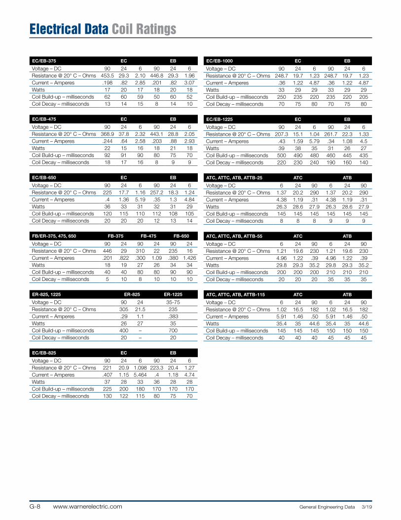
G-8 www.warnerelectric.com General Engineering Data 3/19
Electrical Data Coil Ratings
EC/EB-375 EC EB
Voltage – DC 90 24 6 90 24 6Resistance @ 20° C – Ohms 453.5 29.3 2.10 446.8 29.3 1.96Current – Amperes .198 .82 2.85 .201 .82 3.07Watts 17 20 17 18 20 18Coil Build-up – milliseconds 62 60 59 50 60 52Coil Decay – milliseconds 13 14 15 8 14 10
EC/EB-475 EC EB
Voltage – DC 90 24 6 90 24 6Resistance @ 20° C – Ohms 368.9 37.8 2.32 443.1 28.8 2.05Current – Amperes .244 .64 2.58 .203 .88 2.93Watts 22 15 16 18 21 18Coil Build-up – milliseconds 92 91 90 80 75 70Coil Decay – milliseconds 18 17 16 8 9 9
EC/EB-650 EC EB
Voltage – DC 90 24 6 90 24 6Resistance @ 20° C – Ohms 225 17.7 1.16 257.2 18.3 1.24Current – Amperes .4 1.36 5.19 .35 1.3 4.84Watts 36 33 31 32 31 29Coil Build-up – milliseconds 120 115 110 112 108 105Coil Decay – milliseconds 20 20 20 12 13 14
FB/ER-375, 475, 650 FB-375 FB-475 FB-650
Voltage – DC 90 24 90 24 90 24Resistance @ 20° C – Ohms 446 29 310 22 235 16Current – Amperes .201 .822 .300 1.09 .380 1.426Watts 18 19 27 26 34 34Coil Build-up – milliseconds 40 40 80 80 90 90Coil Decay – milliseconds 5 10 8 10 10 10
ER-825, 1225 ER-825 ER-1225
Voltage – DC 90 24 35-75Resistance @ 20° C – Ohms 305 21.5 235Current – Amperes .29 1.1 .383Watts 26 27 35Coil Build-up – milliseconds 400 – 700Coil Decay – milliseconds 20 – 20
EC/EB-825 EC EB
Voltage – DC 90 24 6 90 24 6Resistance @ 20° C – Ohms 221 20.9 1.098 223.3 20.4 1.27Current – Amperes .407 1.15 5.464 .4 1.18 4.74Watts 37 28 33 36 28 28Coil Build-up – milliseconds 225 200 180 170 170 170Coil Decay – milliseconds 130 122 115 80 75 70
EC/EB-1000 EC EB
Voltage – DC 90 24 6 90 24 6Resistance @ 20° C – Ohms 248.7 19.7 1.23 248.7 19.7 1.23Current – Amperes .36 1.22 4.87 .36 1.22 4.87Watts 33 29 29 33 29 29Coil Build-up – milliseconds 250 235 220 235 220 205Coil Decay – milliseconds 70 75 80 70 75 80
EC/EB-1225 EC EB
Voltage – DC 90 24 6 90 24 6Resistance @ 20° C – Ohms 207.3 15.1 1.04 261.7 22.3 1.33Current – Amperes .43 1.59 5.79 .34 1.08 4.5Watts 39 38 35 31 26 27Coil Build-up – milliseconds 500 490 480 460 445 435Coil Decay – milliseconds 220 230 240 190 160 140
ATC, ATTC, ATB, ATTB-25 ATC ATB
Voltage – DC 6 24 90 6 24 90Resistance @ 20° C – Ohms 1.37 20.2 290 1.37 20.2 290Current – Amperes 4.38 1.19 .31 4.38 1.19 .31Watts 26.3 28.6 27.9 26.3 28.6 27.9Coil Build-up – milliseconds 145 145 145 145 145 145Coil Decay – milliseconds 8 8 8 9 9 9
ATC, ATTC, ATB, ATTB-55 ATC ATB
Voltage – DC 6 24 90 6 24 90Resistance @ 20° C – Ohms 1.21 19.6 230 1.21 19.6 230Current – Amperes 4.96 1.22 .39 4.96 1.22 .39Watts 29.8 29.3 35.2 29.8 29.3 35.2Coil Build-up – milliseconds 200 200 200 210 210 210Coil Decay – milliseconds 20 20 20 35 35 35
ATC, ATTC, ATB, ATTB-115 ATC ATB
Voltage – DC 6 24 90 6 24 90Resistance @ 20° C – Ohms 1.02 16.5 182 1.02 16.5 182Current – Amperes 5.91 1.46 .50 5.91 1.46 .50Watts 35.4 35 44.6 35.4 35 44.6Coil Build-up – milliseconds 145 145 145 150 150 150Coil Decay – milliseconds 40 40 40 45 45 45
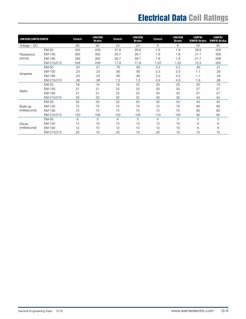
G-9General Engineering Data 3/19 www.warnerelectric.com
Electrical Data Coil Ratings
UM/EM/UMFB/EMFB ClutchUM/EM Brake
ClutchUM/EM Brake
ClutchUM/EM Brake
UMFB/EMFB Brake
UMFB/EMFB Brake
Voltage – DC 90 90 24 24 6 6 24 90
Resistance(ohms)
EM-50 452 429 31.8 28.8 1.9 1.9 28.8 429EM-100 392 392 26.7 26.7 1.8 1.8 21.7 308EM-180 392 392 26.7 26.7 1.8 1.8 21.7 308EM-210/215 248 248 17.9 17.9 1.22 1.22 13.3 205
Amperes
EM-50 .20 .21 .76 .83 3.2 3.2 .83 .21EM-100 .23 .23 .90 .90 3.3 3.3 1.1 .29EM-180 .23 .23 .90 .90 3.3 3.3 1.1 .29EM-210/215 .36 .36 1.3 1.3 4.9 4.9 1.8 .38
Watts
EM-50 18 19 19 20 20 20 20 19EM-100 21 21 22 22 20 20 27 27EM-180 21 21 22 22 20 20 27 27EM-210/215 33 33 32 32 30 30 43 34
Build-up(millisecond)
EM-50 52 53 52 53 52 53 40 40 EM-100 72 75 72 75 72 70 80 80EM-180 72 75 72 75 72 70 80 80EM-210/215 120 100 120 100 110 100 90 90
Decay(millisecond)
EM-50 6 5 6 5 6 5 5 5EM-100 12 10 12 10 12 10 8 8EM-180 12 10 12 10 12 10 8 8EM-210/215 20 10 20 10 20 10 10 10
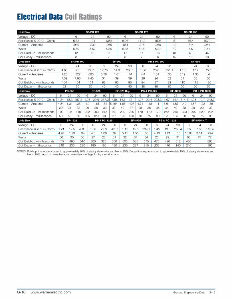
G-10 www.warnerelectric.com General Engineering Data 3/19
Electrical Data Coil Ratings
Unit Size SF/PB 120 SF/PB 170 SF/PB 250
Voltage – DC 6 24 90 6 24 90 6 24 90Resistance @ 20°C – Ohms 6.32 104 1386 6.96 111.2 1506 5 76.4 1079Current – Amperes .949 .230 .065 .861 .215 .060 1.2 .314 .084Watts 5.69 5.52 5.85 5.85 5.16 5.37 7.2 7.5 7.51Coil Build-up – milliseconds 12 12 11 17 17 16 48 48 44Coil Decay – milliseconds 8 8 7 8 7 6 15 15 13Unit Size SF/PB 400 SF-500 PB & PC 500 SF-650
Voltage – DC 6 24 90 6 24 90 6 24 90 6 24 90Resistance @ 20°C – Ohms 4.88 73 1087 1.076 14.9 206.1 1.36 23.8 251.1 1.16 17.7 225Current – Amperes 1.23 .322 .083 5.58 1.61 .44 4.4 1.01 .36 5.19 1.36 .4Watts 7.39 7.96 7.45 34 39 39 26 24 32 31 33 36Coil Build-up – milliseconds 154 154 154 82 85 90 84 87 93 110 115 120Coil Decay – milliseconds 62 60 55 40 40 40 38 35 30 50 50 50Unit Size PB-650 SF-825 SF-825 Brg PB & PC 825 SF-1000 PB & PC 1000
Voltage – DC 6 24 90 6 24 90 6 24 90 6 24 90 6 24 90 6 24 90Resistance @ 20°C – Ohms 1.24 18.3 257.2 1.23 20.9 267.0 1.098 14.6 221 1.27 20.4 223.3 1.07 14.4 214.4 1.23 19.7 248.7Current – Amperes 4.84 1.31 .35 4.9 1.15 .34 5.464 1.65 .407 4.74 1.18 .4 5.61 1.67 .42 4.87 1.22 .36Watts 29 31 32 29 28 30 33 40 37 28 28 36 34 40 38 29 29 33Coil Build-up – milliseconds 100 105 110 222 200 245 180 200 225 170 170 170 256 275 283 205 220 235Coil Decay – milliseconds 50 50 50 105 120 100 115 120 130 70 75 80 123 105 90 70 75 80Unit Size SF-1225 PB & PC 1225 SF-1525 PB & PC 1525 SF-1525 H.T.
Voltage – DC 6 24 90 6 24 90 6 24 90 6 24 90 6 24 90Resistance @ 20°C – Ohms 1.21 19.5 268.3 1.33 22.3 261.7 1.11 15.5 239.1 1.45 19.8 258.4 .55 7.63 113.4Current – Amperes 4.97 1.23 .34 4.5 1.08 .34 5.41 1.55 .38 4.13 1.21 .35 10.83 3.14 .794Watts 30 30 30 27 26 31 32 37 34 25 29 31 65 75 72Coil Build-up – milliseconds 475 490 510 300 320 350 505 535 575 470 490 512 480 560Coil Decay – milliseconds 240 230 220 190 190 190 230 237 215 200 170 140 210 160
NOTES: Build-up time equals current to approximately 90% of steady state value and flux to 90%. Decay time equals current to approximately 10% of steady state value and flux to 10%. Approximately because current leads or lags flux by a small amount.
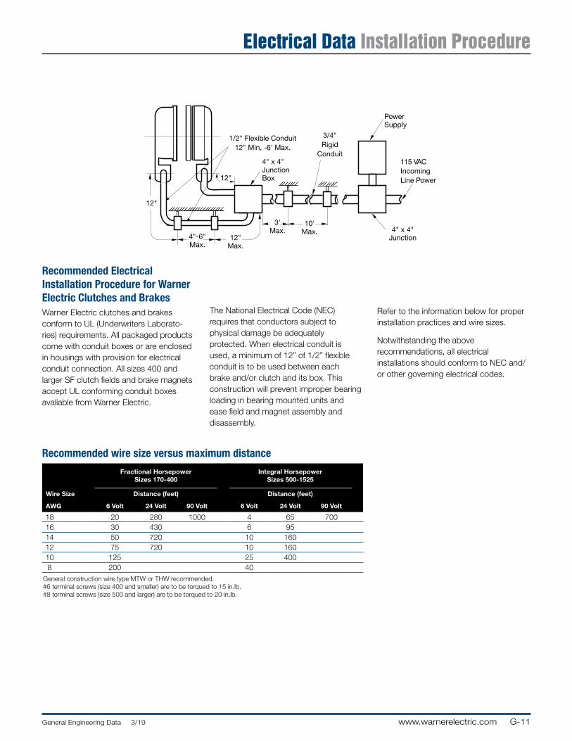
G-11General Engineering Data 3/19 www.warnerelectric.com
1/2" Flexible Conduit12" Min, -6' Max.
4" x 4" Junction Box
Power Supply
115 VACIncomingLine Power
4" x 4" Junction
10' Max.
3' Max.
12" Max.
4"-6" Max.
12"
12"
3/4" Rigid
Conduit
Recommended Electrical In stal la tion Procedure for Warner Electric Clutches and BrakesWarner Electric clutches and brakes conform to UL (Un der writ ers Lab o ra to-ries) requirements. All packaged products come with conduit boxes or are enclosed in housings with provision for electrical conduit connection. All sizes 400 and larger SF clutch fields and brake magnets accept UL conforming conduit boxes avaliable from Warner Electric.
The National Electrical Code (NEC) requires that con duc tors subject to physical damage be adequately pro tect ed. When electrical conduit is used, a minimum of 12” of 1/2” flexible conduit is to be used between each brake and/or clutch and its box. This construction will prevent improper bearing loading in bearing mounted units and ease field and magnet assembly and disassembly.
Refer to the information below for proper installation practices and wire sizes.
Notwithstanding the above rec om men da tions, all electrical installations should conform to NEC and/or other gov ern ing electrical codes.
Electrical Data Installation Procedure
Recommended wire size versus maximum distance
Fractional HorsepowerSiz es 170-400
Integral HorsepowerSizes 500-1525
Wire Size Dis tance (feet) Dis tance (feet)
AWG 6 Volt 24 Volt 90 Volt 6 Volt 24 Volt 90 Volt
18 20 280 1000 4 65 70016 30 430 6 9514 50 720 10 16012 75 720 10 16010 125 25 400 8 200 40
General construction wire type MTW or THW recommended.#6 terminal screws (size 400 and smaller) are to be torqued to 15 in.lb.#8 terminal screws (size 500 and larger) are to be torqued to 20 in.lb.
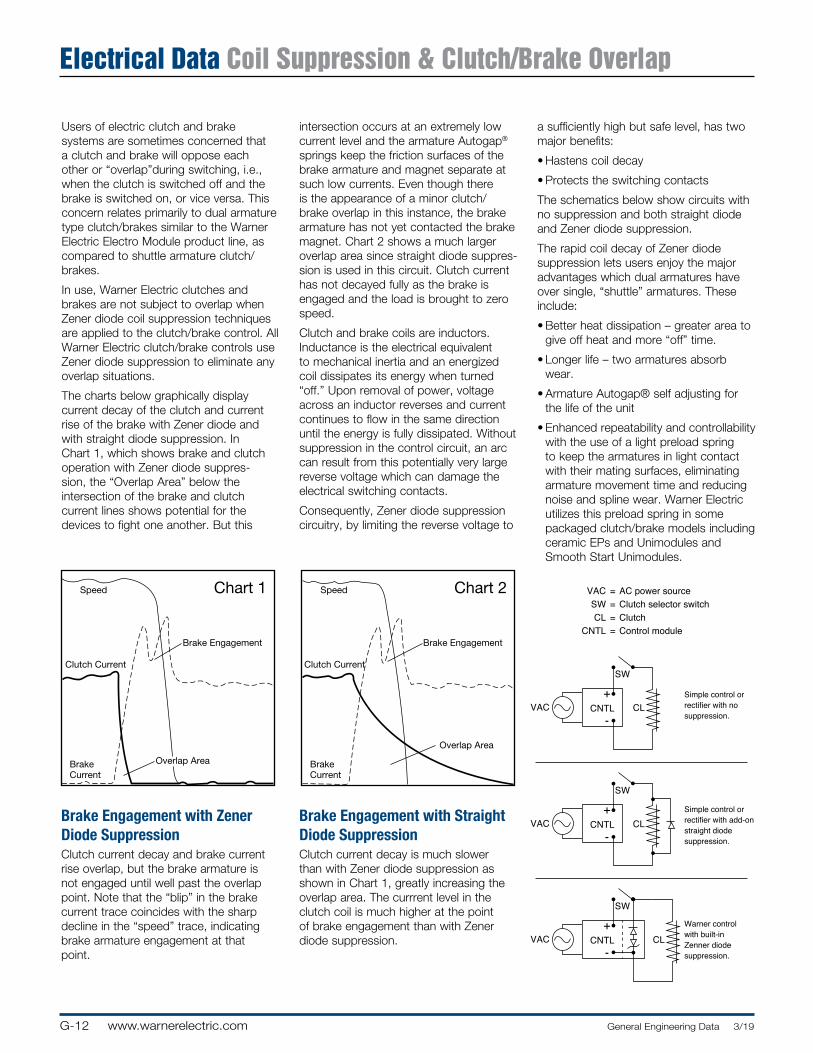
G-12 www.warnerelectric.com General Engineering Data 3/19
Electrical Data Coil Suppression & Clutch/Brake Overlap
Users of electric clutch and brake systems are sometimes concerned that a clutch and brake will oppose each other or “overlap”during switching, i.e., when the clutch is switched off and the brake is switched on, or vice versa. This concern relates primarily to dual armature type clutch/brakes similar to the Warner Electric Electro Module product line, as compared to shuttle armature clutch/brakes.
In use, Warner Electric clutches and brakes are not subject to overlap when Zener diode coil suppression tech niques are applied to the clutch/brake control. All Warner Electric clutch/brake controls use Zener diode suppression to eliminate any overlap situations.
The charts below graphically display current decay of the clutch and current rise of the brake with Zener diode and with straight diode suppression. In Chart 1, which shows brake and clutch operation with Zener diode sup pres-sion, the “Overlap Area” below the intersection of the brake and clutch current lines shows potential for the devices to fight one another. But this
Brake Engagement with Zener Diode SuppressionClutch current decay and brake current rise overlap, but the brake armature is not engaged until well past the overlap point. Note that the “blip” in the brake current trace coincides with the sharp decline in the “speed” trace, indicating brake armature engagement at that point.
Brake Engagement with Straight Diode Sup pres sionClutch current decay is much slower than with Zener diode suppression as shown in Chart 1, greatly increasing the overlap area. The currrent level in the clutch coil is much higher at the point of brake engagement than with Zener diode suppression.
Chart 1Speed
Brake Engagement
Clutch Current
BrakeCurrent
Overlap Area
Chart 2Speed
Brake Engagement
Clutch Current
BrakeCurrent
Overlap Area
Chart 1Speed
Brake Engagement
Clutch Current
BrakeCurrent
Overlap Area
Chart 2Speed
Brake Engagement
Clutch Current
BrakeCurrent
Overlap Area
CNTL+
-
CNTL CL
SW
VAC +
-
CNTLVAC +
-CL
SW
SW
CLVAC
Simple control orrectifier with add-onstraight diodesuppression.
Warner controlwith built-in Zenner diodesuppression.
Simple control orrectifier with no suppression.
VAC = AC power source SW = Clutch selector switch CL = Clutch CNTL = Control module
intersection occurs at an ex treme ly low current level and the armature Autogap® springs keep the friction sur fac es of the brake armature and magnet separate at such low currents. Even though there is the ap pear anc e of a minor clutch/brake overlap in this in stance, the brake armature has not yet contacted the brake magnet. Chart 2 shows a much larger overlap area since straight diode sup pres-sion is used in this circuit. Clutch current has not decayed fully as the brake is engaged and the load is brought to zero speed.
Clutch and brake coils are inductors. Inductance is the elec tri cal equivalent to mechanical inertia and an en er gized coil dissipates its energy when turned “off.” Upon removal of power, voltage across an inductor reverses and current continues to flow in the same direction until the energy is fully dissipated. Without sup pres sion in the control circuit, an arc can result from this potentially very large reverse voltage which can damage the electrical switching contacts.
Consequently, Zener diode suppression circuitry, by limiting the reverse voltage to
a sufficiently high but safe level, has two major benefits:
• Hastens coil decay
• Protects the switching contacts
The schematics below show circuits with no sup pres sion and both straight diode and Zener diode suppression.
The rapid coil decay of Zener diode suppression lets users enjoy the major advantages which dual armatures have over single, “shuttle” armatures. These include:
• Better heat dissipation – greater area to give off heat and more “off” time.
• Longer life – two armatures absorb wear.
• Armature Autogap® self adjusting for the life of the unit
• Enhanced repeatability and controllability with the use of a light preload spring to keep the armatures in light contact with their mating surfaces, elim i nat ing armature movement time and reducing noise and spline wear. Warner Electric utilizes this preload spring in some packaged clutch/brake models including ceramic EPs and Unimodules and Smooth Start Unimodules.
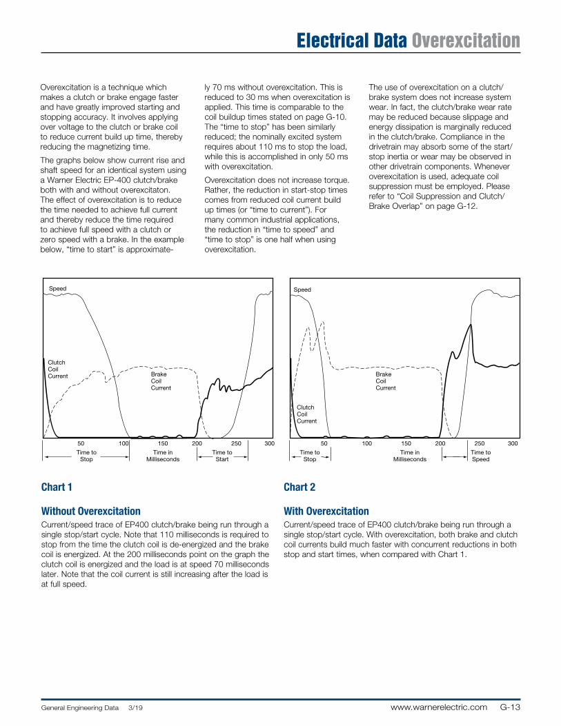
G-13General Engineering Data 3/19 www.warnerelectric.com
Electrical Data Overexcitation
Overexcitation is a technique which makes a clutch or brake engage faster and have greatly improved starting and stopping accuracy. It involves applying over voltage to the clutch or brake coil to reduce current build up time, thereby reducing the magnetizing time.
The graphs below show current rise and shaft speed for an identical system using a Warner Electric EP-400 clutch/brake both with and without overexcitaton. The effect of overexcitation is to reduce the time needed to achieve full current and thereby reduce the time required to achieve full speed with a clutch or zero speed with a brake. In the example below, “time to start” is ap prox i mate-
Chart 1
Without OverexcitationCurrent/speed trace of EP400 clutch/brake being run through a single stop/start cycle. Note that 110 mil li sec onds is required to stop from the time the clutch coil is de-energized and the brake coil is energized. At the 200 milliseconds point on the graph the clutch coil is energized and the load is at speed 70 milliseconds later. Note that the coil current is still increasing after the load is at full speed.
Chart 2
With OverexcitationCurrent/speed trace of EP400 clutch/brake being run through a single stop/start cycle. With overexcitation, both brake and clutch coil currents build much faster with concurrent reductions in both stop and start times, when compared with Chart 1.
ly 70 ms without overexcitation. This is reduced to 30 ms when overexcitation is applied. This time is com pa ra ble to the coil buildup times stated on page G-10. The “time to stop” has been similarly reduced; the nominally excited system requires about 110 ms to stop the load, while this is accomplished in only 50 ms with overexcitation.
Overexcitation does not increase torque. Rather, the reduction in start-stop times comes from reduced coil current build up times (or “time to current”). For many common industrial applications, the reduction in “time to speed” and “time to stop” is one half when using overexcitation.
Speed
BrakeCoilCurrent
ClutchCoilCurrent
50 100 150 200 250 300
Time toStop
Time inMilliseconds
Time toStart
Speed
BrakeCoilCurrent
ClutchCoilCurrent
50 100 150 200 250 300
Time toStop
Time inMilliseconds
Time toSpeed
The use of overexcitation on a clutch/brake system does not increase system wear. In fact, the clutch/brake wear rate may be reduced because slippage and energy dissipation is marginally reduced in the clutch/brake. Compliance in the drivetrain may absorb some of the start/stop inertia or wear may be observed in other drivetrain components. Whenever overexcitation is used, adequate coil suppression must be employed. Please refer to “Coil Suppression and Clutch/Brake Overlap” on page G-12.
G-14 www.warnerelectric.com General Engineering Data 3/19
Notes
B-1www.warnerelectric.comBushing Part Numbers 3/19
Bushing Part Numbers B
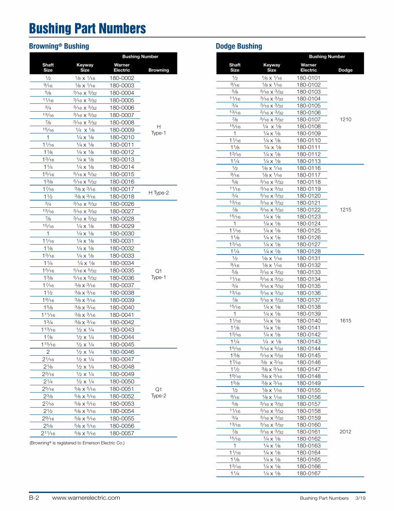
B-2 www.warnerelectric.com Bushing Part Numbers 3/19
Browning® Bushing Dodge Bushing
Bushing Part Numbers
Shaft Size
Keyway Size
Bushing Number
Warner Electric Browning
1⁄2 1⁄8 x 1⁄16 180-0002
H Type-1
9⁄16 1⁄8 x 1⁄16 180-00035⁄8 3⁄16 x 3⁄32 180-0004
11⁄16 3⁄16 x 3⁄32 180-00053⁄4 3⁄16 x 3⁄32 180-0006
13⁄16 3⁄16 x 3⁄32 180-00077⁄8 3⁄16 x 3⁄32 180-0008
15⁄16 1⁄4 x 1⁄8 180-00091 1⁄4 x 1⁄8 180-0010
11⁄16 1⁄4 x 1⁄8 180-001111⁄8 1⁄4 x 1⁄8 180-001213⁄16 1⁄4 x 1⁄8 180-001311⁄4 1⁄4 x 1⁄8 180-001415⁄16 5⁄16 x 5⁄32 180-001513⁄8 5⁄16 x 5⁄32 180-0016 17⁄16 3⁄8 x 3⁄16 180-0017
H Type-211⁄2 3⁄8 x 3⁄16 180-00183⁄4 3⁄16 x 3⁄32 180-0026
Q1 Type-1
13⁄16 3⁄16 x 3⁄32 180-00277⁄8 3⁄16 x 3⁄32 180-0028
15⁄16 1⁄4 x 1⁄8 180-00291 1⁄4 x 1⁄8 180-0030
11⁄16 1⁄4 x 1⁄8 180-003111⁄8 1⁄4 x 1⁄8 180-003213⁄16 1⁄4 x 1⁄8 180-003311⁄4 1⁄4 x 1⁄8 180-003415⁄16 5⁄16 x 5⁄32 180-003513⁄8 5⁄16 x 5⁄32 180-003617⁄16 3⁄8 x 3⁄16 180-003711⁄2 3⁄8 x 3⁄16 180-003819⁄16 3⁄8 x 3⁄16 180-003915⁄8 3⁄8 x 3⁄16 180-0040
111⁄16 3⁄8 x 3⁄16 180-004113⁄4 3⁄8 x 3⁄16 180-0042
113⁄16 1⁄2 x 1⁄4 180-004317⁄8 1⁄2 x 1⁄4 180-0044
115⁄16 1⁄2 x 1⁄4 180-0045 2 1⁄2 x 1⁄4 180-0046
Q1 Type-2
21⁄16 1⁄2 x 1⁄4 180-004721⁄8 1⁄2 x 1⁄4 180-004823⁄16 1⁄2 x 1⁄4 180-004921⁄4 1⁄2 x 1⁄4 180-005025⁄16 5⁄8 x 5⁄16 180-005123⁄8 5⁄8 x 5⁄16 180-005227⁄16 5⁄8 x 5⁄16 180-005321⁄2 5⁄8 x 5⁄16 180-005429⁄16 5⁄8 x 5⁄16 180-005525⁄8 5⁄8 x 5⁄16 180-0056
211⁄16 5⁄8 x 5⁄16 180-0057
(Browning® is registered to Emerson Electric Co.)
Shaft Size
Keyway Size
Bushing Number
Warner Electric Dodge
1⁄2 1⁄8 x 1⁄16 180-0101
1210
9⁄16 1⁄8 x 1⁄16 180-01025⁄8 3⁄16 x 3⁄32 180-0103
11⁄16 3⁄16 x 3⁄32 180-01043⁄4 3⁄16 x 3⁄32 180-0105
13⁄16 3⁄16 x 3⁄32 180-01067⁄8 3⁄16 x 3⁄32 180-0107
15⁄16 1⁄4 x 1⁄8 180-01081 1⁄4 x 1⁄8 180-0109
11⁄16 1⁄4 x 1⁄8 180-011011⁄8 1⁄4 x 1⁄8 180-011113⁄16 1⁄4 x 1⁄8 180-011211⁄4 1⁄4 x 1⁄8 180-01131⁄2 1⁄8 x 1⁄16 180-0116
1215
9⁄16 1⁄8 x 1⁄16 180-01175⁄8 3⁄16 x 3⁄32 180-0118
11⁄16 3⁄16 x 3⁄32 180-01193⁄4 3⁄16 x 3⁄32 180-0120
13⁄16 3⁄16 x 3⁄32 180-01217⁄8 3⁄16 x 3⁄32 180-0122
15⁄16 1⁄4 x 1⁄8 180-01231 1⁄4 x 1⁄8 180-0124
11⁄16 1⁄4 x 1⁄8 180-012511⁄8 1⁄4 x 1⁄8 180-012613⁄16 1⁄4 x 1⁄8 180-012711⁄4 1⁄4 x 1⁄8 180-01281⁄2 1⁄8 x 1⁄16 180-0131
1615
9⁄16 1⁄8 x 1⁄16 180-01325⁄8 3⁄16 x 3⁄32 180-0133
11⁄16 3⁄16 x 3⁄32 180-01343⁄4 3⁄16 x 3⁄32 180-0135
13⁄16 3⁄16 x 3⁄32 180-01367⁄8 3⁄16 x 3⁄32 180-0137
15⁄16 1⁄4 x 1⁄8 180-01381 1⁄4 x 1⁄8 180-0139
11⁄16 1⁄4 x 1⁄8 180-014011⁄8 1⁄4 x 1⁄8 180-014113⁄16 1⁄4 x 1⁄8 180-014211⁄4 1⁄4 x 1⁄8 180-014315⁄16 5⁄16 x 5⁄32 180-014413⁄8 5⁄16 x 5⁄32 180-014517⁄16 3⁄8 x 3⁄16 180-014611⁄2 3⁄8 x 3⁄16 180-014719⁄16 3⁄8 x 3⁄16 180-014815⁄8 3⁄8 x 3⁄16 180-01491⁄2 1⁄8 x 1⁄16 180-0155
2012
9⁄16 1⁄8 x 1⁄16 180-01565⁄8 3⁄16 x 3⁄32 180-0157
11⁄16 3⁄16 x 3⁄32 180-01583⁄4 3⁄16 x 3⁄32 180-0159
13⁄16 3⁄16 x 3⁄32 180-01607⁄8 3⁄16 x 3⁄32 180-0161
15⁄16 1⁄4 x 1⁄8 180-01621 1⁄4 x 1⁄8 180-0163
11⁄16 1⁄4 x 1⁄8 180-016411⁄8 1⁄4 x 1⁄8 180-016513⁄16 1⁄4 x 1⁄8 180-016611⁄4 1⁄4 x 1⁄8 180-0167
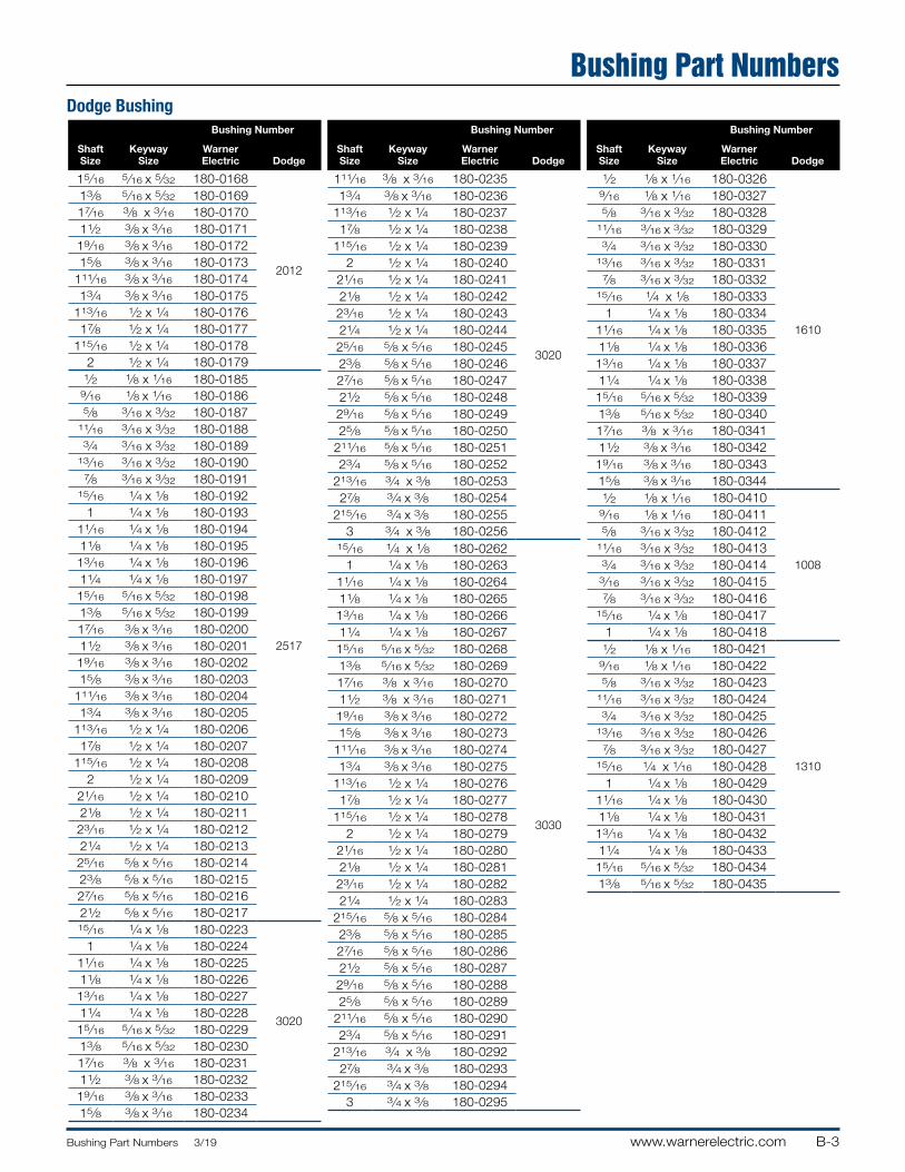
B-3www.warnerelectric.comBushing Part Numbers 3/19
Dodge Bushing
Bushing Part Numbers
Shaft Size
Keyway Size
Bushing Number
Warner Electric Dodge
15⁄16 5⁄16 x 5⁄32 180-0168
2012
13⁄8 5⁄16 x 5⁄32 180-016917⁄16 3⁄8 x 3⁄16 180-017011⁄2 3⁄8 x 3⁄16 180-017119⁄16 3⁄8 x 3⁄16 180-017215⁄8 3⁄8 x 3⁄16 180-0173
111⁄16 3⁄8 x 3⁄16 180-017413⁄4 3⁄8 x 3⁄16 180-0175
113⁄16 1⁄2 x 1⁄4 180-017617⁄8 1⁄2 x 1⁄4 180-0177
115⁄16 1⁄2 x 1⁄4 180-01782 1⁄2 x 1⁄4 180-0179
1⁄2 1⁄8 x 1⁄16 180-0185
2517
9⁄16 1⁄8 x 1⁄16 180-01865⁄8 3⁄16 x 3⁄32 180-0187
11⁄16 3⁄16 x 3⁄32 180-01883⁄4 3⁄16 x 3⁄32 180-0189
13⁄16 3⁄16 x 3⁄32 180-01907⁄8 3⁄16 x 3⁄32 180-0191
15⁄16 1⁄4 x 1⁄8 180-01921 1⁄4 x 1⁄8 180-0193
11⁄16 1⁄4 x 1⁄8 180-019411⁄8 1⁄4 x 1⁄8 180-019513⁄16 1⁄4 x 1⁄8 180-019611⁄4 1⁄4 x 1⁄8 180-019715⁄16 5⁄16 x 5⁄32 180-019813⁄8 5⁄16 x 5⁄32 180-019917⁄16 3⁄8 x 3⁄16 180-020011⁄2 3⁄8 x 3⁄16 180-020119⁄16 3⁄8 x 3⁄16 180-020215⁄8 3⁄8 x 3⁄16 180-0203
111⁄16 3⁄8 x 3⁄16 180-020413⁄4 3⁄8 x 3⁄16 180-0205
113⁄16 1⁄2 x 1⁄4 180-020617⁄8 1⁄2 x 1⁄4 180-0207
115⁄16 1⁄2 x 1⁄4 180-02082 1⁄2 x 1⁄4 180-0209
21⁄16 1⁄2 x 1⁄4 180-021021⁄8 1⁄2 x 1⁄4 180-021123⁄16 1⁄2 x 1⁄4 180-021221⁄4 1⁄2 x 1⁄4 180-021325⁄16 5⁄8 x 5⁄16 180-021423⁄8 5⁄8 x 5⁄16 180-021527⁄16 5⁄8 x 5⁄16 180-021621⁄2 5⁄8 x 5⁄16 180-021715⁄16 1⁄4 x 1⁄8 180-0223
3020
1 1⁄4 x 1⁄8 180-022411⁄16 1⁄4 x 1⁄8 180-022511⁄8 1⁄4 x 1⁄8 180-022613⁄16 1⁄4 x 1⁄8 180-022711⁄4 1⁄4 x 1⁄8 180-022815⁄16 5⁄16 x 5⁄32 180-022913⁄8 5⁄16 x 5⁄32 180-023017⁄16 3⁄8 x 3⁄16 180-023111⁄2 3⁄8 x 3⁄16 180-023219⁄16 3⁄8 x 3⁄16 180-023315⁄8 3⁄8 x 3⁄16 180-0234
Shaft Size
Keyway Size
Bushing Number
Warner Electric Dodge
111⁄16 3⁄8 x 3⁄16 180-0235
3020
13⁄4 3⁄8 x 3⁄16 180-0236113⁄16 1⁄2 x 1⁄4 180-023717⁄8 1⁄2 x 1⁄4 180-0238
115⁄16 1⁄2 x 1⁄4 180-02392 1⁄2 x 1⁄4 180-0240
21⁄16 1⁄2 x 1⁄4 180-024121⁄8 1⁄2 x 1⁄4 180-024223⁄16 1⁄2 x 1⁄4 180-024321⁄4 1⁄2 x 1⁄4 180-024425⁄16 5⁄8 x 5⁄16 180-024523⁄8 5⁄8 x 5⁄16 180-024627⁄16 5⁄8 x 5⁄16 180-024721⁄2 5⁄8 x 5⁄16 180-024829⁄16 5⁄8 x 5⁄16 180-024925⁄8 5⁄8 x 5⁄16 180-0250
211⁄16 5⁄8 x 5⁄16 180-025123⁄4 5⁄8 x 5⁄16 180-0252
213⁄16 3⁄4 x 3⁄8 180-025327⁄8 3⁄4 x 3⁄8 180-0254
215⁄16 3⁄4 x 3⁄8 180-02553 3⁄4 x 3⁄8 180-0256
15⁄16 1⁄4 x 1⁄8 180-0262
3030
1 1⁄4 x 1⁄8 180-026311⁄16 1⁄4 x 1⁄8 180-026411⁄8 1⁄4 x 1⁄8 180-026513⁄16 1⁄4 x 1⁄8 180-026611⁄4 1⁄4 x 1⁄8 180-026715⁄16 5⁄16 x 5⁄32 180-026813⁄8 5⁄16 x 5⁄32 180-026917⁄16 3⁄8 x 3⁄16 180-027011⁄2 3⁄8 x 3⁄16 180-027119⁄16 3⁄8 x 3⁄16 180-027215⁄8 3⁄8 x 3⁄16 180-0273
111⁄16 3⁄8 x 3⁄16 180-027413⁄4 3⁄8 x 3⁄16 180-0275
113⁄16 1⁄2 x 1⁄4 180-027617⁄8 1⁄2 x 1⁄4 180-0277
115⁄16 1⁄2 x 1⁄4 180-02782 1⁄2 x 1⁄4 180-0279
21⁄16 1⁄2 x 1⁄4 180-028021⁄8 1⁄2 x 1⁄4 180-028123⁄16 1⁄2 x 1⁄4 180-028221⁄4 1⁄2 x 1⁄4 180-0283
215⁄16 5⁄8 x 5⁄16 180-028423⁄8 5⁄8 x 5⁄16 180-028527⁄16 5⁄8 x 5⁄16 180-028621⁄2 5⁄8 x 5⁄16 180-028729⁄16 5⁄8 x 5⁄16 180-028825⁄8 5⁄8 x 5⁄16 180-0289
211⁄16 5⁄8 x 5⁄16 180-029023⁄4 5⁄8 x 5⁄16 180-0291
213⁄16 3⁄4 x 3⁄8 180-029227⁄8 3⁄4 x 3⁄8 180-0293
215⁄16 3⁄4 x 3⁄8 180-02943 3⁄4 x 3⁄8 180-0295
Shaft Size
Keyway Size
Bushing Number
Warner Electric Dodge
1⁄2 1⁄8 x 1⁄16 180-0326
1610
9⁄16 1⁄8 x 1⁄16 180-03275⁄8 3⁄16 x 3⁄32 180-0328
11⁄16 3⁄16 x 3⁄32 180-03293⁄4 3⁄16 x 3⁄32 180-0330
13⁄16 3⁄16 x 3⁄32 180-03317⁄8 3⁄16 x 3⁄32 180-0332
15⁄16 1⁄4 x 1⁄8 180-03331 1⁄4 x 1⁄8 180-0334
11⁄16 1⁄4 x 1⁄8 180-033511⁄8 1⁄4 x 1⁄8 180-033613⁄16 1⁄4 x 1⁄8 180-033711⁄4 1⁄4 x 1⁄8 180-033815⁄16 5⁄16 x 5⁄32 180-033913⁄8 5⁄16 x 5⁄32 180-034017⁄16 3⁄8 x 3⁄16 180-034111⁄2 3⁄8 x 3⁄16 180-034219⁄16 3⁄8 x 3⁄16 180-034315⁄8 3⁄8 x 3⁄16 180-03441⁄2 1⁄8 x 1⁄16 180-0410
1008
9⁄16 1⁄8 x 1⁄16 180-04115⁄8 3⁄16 x 3⁄32 180-0412
11⁄16 3⁄16 x 3⁄32 180-04133⁄4 3⁄16 x 3⁄32 180-0414
3⁄16 3⁄16 x 3⁄32 180-04157⁄8 3⁄16 x 3⁄32 180-0416
15⁄16 1⁄4 x 1⁄8 180-04171 1⁄4 x 1⁄8 180-0418
1⁄2 1⁄8 x 1⁄16 180-0421
1310
9⁄16 1⁄8 x 1⁄16 180-04225⁄8 3⁄16 x 3⁄32 180-0423
11⁄16 3⁄16 x 3⁄32 180-04243⁄4 3⁄16 x 3⁄32 180-0425
13⁄16 3⁄16 x 3⁄32 180-04267⁄8 3⁄16 x 3⁄32 180-0427
15⁄16 1⁄4 x 1⁄16 180-04281 1⁄4 x 1⁄8 180-0429
11⁄16 1⁄4 x 1⁄8 180-043011⁄8 1⁄4 x 1⁄8 180-043113⁄16 1⁄4 x 1⁄8 180-043211⁄4 1⁄4 x 1⁄8 180-043315⁄16 5⁄16 x 5⁄32 180-043413⁄8 5⁄16 x 5⁄32 180-0435

B-4 www.warnerelectric.com Bushing Part Numbers 3/19
Notes
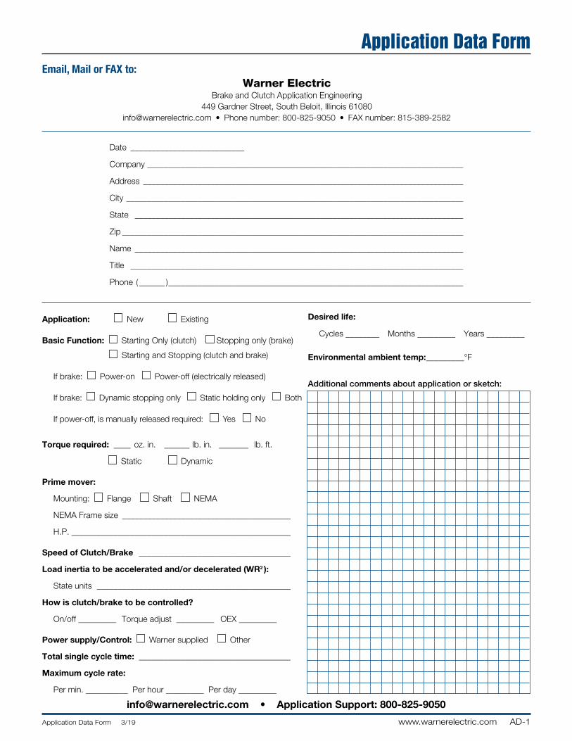
AD-1Application Data Form 3/19 www.warnerelectric.com
Email, Mail or FAX to:Warner Electric
Brake and Clutch Application Engineering 449 Gardner Street, South Beloit, Illinois 61080
[email protected] • Phone number: 800-825-9050 • FAX number: 815-389-2582
Date ___________________________
Company ___________________________________________________________________________
Address ____________________________________________________________________________
City ________________________________________________________________________________
State ______________________________________________________________________________
Zip _________________________________________________________________________________
Name ______________________________________________________________________________
Title _______________________________________________________________________________
Phone ( ______ ) ______________________________________________________________________
Desired life:
Cycles ________ Months _________ Years _________
Environmental ambient temp: _________°F
Additional comments about application or sketch:
Application: New Existing
Basic Function: Starting Only (clutch) Stopping only (brake)
Starting and Stopping (clutch and brake)
If brake: Power-on Power-off (electrically released)
If brake: Dynamic stopping only Static holding only Both
If power-off, is manually released required: Yes No
Torque required: ____ oz. in. ______ lb. in. _______ lb. ft.
Static Dynamic
Prime mover:
Mounting: Flange Shaft NEMA
NEMA Frame size ________________________________________
H.P. ____________________________________________________
Speed of Clutch/Brake ____________________________________
Load inertia to be accelerated and/or decelerated (WR2 ):
State units ______________________________________________
How is clutch/brake to be controlled?
On/off _________ Torque adjust _________ OEX _________
Power supply/Control: Warner supplied Other
Total single cycle time: ____________________________________
Maximum cycle rate:
Per min. __________ Per hour _________ Per day _________
Application Data Form
[email protected] • Application Support: 800-825-9050

Notes
AD-2 www.warnerelectric.com Application Data Form 3/19
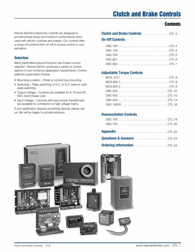
CTL-1Clutch and Brake Controls 3/19 www.warnerelectric.com
Clutch and Brake ControlsContents
Clutch and Brake Controls . . . . . . . . . . . . . . . . . CTL-2
On-Off Controls
CBC-100 . . . . . . . . . . . . . . . . . . . . . . . . . . . . . . . . CTL-4
CBC-150 . . . . . . . . . . . . . . . . . . . . . . . . . . . . . . . . CTL-4
CBC-160 . . . . . . . . . . . . . . . . . . . . . . . . . . . . . . . . CTL-5
CBC-801 . . . . . . . . . . . . . . . . . . . . . . . . . . . . . . . . CTL-6
CBC-802 . . . . . . . . . . . . . . . . . . . . . . . . . . . . . . . . CTL-7
Adjustable Torque Controls MCS-103-1 . . . . . . . . . . . . . . . . . . . . . . . . . . . . . . CTL-8
MCS-805-1 . . . . . . . . . . . . . . . . . . . . . . . . . . . . . . CTL-9
MCS-805-2 . . . . . . . . . . . . . . . . . . . . . . . . . . . . . . CTL-9
CBC-300 . . . . . . . . . . . . . . . . . . . . . . . . . . . . . . . CTL-10
CBC-500 . . . . . . . . . . . . . . . . . . . . . . . . . . . . . . . CTL-12
CBC-550 . . . . . . . . . . . . . . . . . . . . . . . . . . . . . . . CTL-14
CBC-1825R . . . . . . . . . . . . . . . . . . . . . . . . . . . . . CTL-16
Overexcitation Controls CBC-700 . . . . . . . . . . . . . . . . . . . . . . . . . . . . . . . CTL-18
CBC-750 . . . . . . . . . . . . . . . . . . . . . . . . . . . . . . . CTL-20
Appendix . . . . . . . . . . . . . . . . . . . . . . . . . . . . . . . CTL-22
Questions & Answers . . . . . . . . . . . . . . . . . . . . CTL-23
Ordering Information . . . . . . . . . . . . . . . . . . . . CTL-24
Warner Electric’s electronic controls are designed to provide simple setup and maximum performance when used with electric clutches and brakes . Our controls offer a range of functions from on-off to torque control to over-excitation .
SelectionMany parameters beyond function can impact control selection . Warner Electric produces a variety of control options to suit numerous application requirements . Control selection parameters include:
• Mounting Location – Panel or conduit box mounting
• Switching – Relay switching of A .C . or D .C . lines or solid state switching
• Output Voltage – Controls are avail able for 6, 24 and 90 VDC clutch/brake coils
• Input Voltage – Controls with input power transformers are available for connection to high voltage mains .
If your application requires something special, please call us . We will be happy to provide solutions .
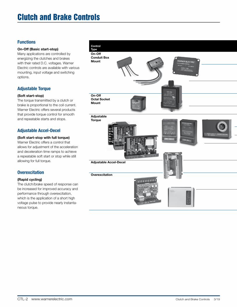
CTL-2 www.warnerelectric.com Clutch and Brake Controls 3/19
ControlType
ModelNumber
No. ofChannels
TorqueControl
Channels
A.C.Input
Voltages
D.C. Output
VoltagesOver-
Excitation
Customer SuppliedSwitchingOptions Description
PageNumber
On-OffConduit Box Mount
CBC-100-1 1 No 120 90 No Relay A .C . Single channel control tomount inside standard
conduit boxCTL-4CBC-100-2 1 No 220/240
CBC-150-1 2 No 120 90 No Relay A .C . Dual channel control for clutch/brake to
mount inside module conduit box
CTL-4CBC-150-2 2 No 220/240
CBC-160-1 120 Single channel control with torque adjust for module
electrically released brakesCTL-5CBC-160-2 1 1 220/240 90 No Relay A .C .
On-Off Octal Socket Mount
CBC-801-1 2 No 120 90 No Relay D .C .Dual channel control for 2 clutches and/or brakes
CTL-6CBC-801-2 2 220/240
CBC-802 2 No 120 90 No Transistor or Dual channel control with transistor switching
CTL-7Relay D .C .
AdjustableTorque
MCS-103-1 2 1 120 90 No Relay D .C . Dual channel controlwith torque adjust for one channel
CTL-8
MCS-805-1 1 1 120/240 35-75 No Relay D .C . Single adjustable channel controlfor use with ER-1225 brake .
CTL-9MCS-805-2CBC-300 2 2 120 90 No Transistor or Dual channel adjustable
current controlCTL-10 to
CTL-11CBC-300-1 Relay D .C .CBC-500-90 2 2 120 90 No Dual channel control for two
clutches and/or brakes withtwo torque adjust channels;
Emergency stop input
CTL-12 to CTL-15
CBC-500-24 2 2 24-30 24 No Transistor orCBC-550-90 2 2 120/220/240/380/480 90 No Relay D .C .CBC-550-24 2 2 120/220/240/380/480 24 No
Adjustable Accel-Decel CBC-1825-R 2 2 120 90 No Transistor or Dual channel adjustable time ramp with short
circuit protection
CTL-16 to CTL-17
Relay D .C .
Overexcitation CBC-700-90 2 No 120 90 Yes Transistor or Dual channel compact overexcitation control for
24 or 90 volt clutches and brakes
CTL-18 to CTL-19
CBC-700-24 2 24–28 24 Relay D .C .
CBC-750-6 2 2 120/220/240 6 Yes Transistor, Dual channel full function overexcitation control;
provides input/output logic, torque adjustable current
and remote inputs
CTL-20 to CTL-21
Relay D .C . orTriac A .C .
Clutch and Brake Controls
FunctionsOn-Off (Basic start-stop)Many applications are controlled by energizing the clutches and brakes with their rated D .C . voltages . Warner Electric controls are available with various mounting, input voltage and switching options .
Adjustable Torque(Soft start-stop)The torque transmitted by a clutch or brake is proportional to the coil current . Warner Electric offers several products that provide torque control for smooth and repeatable starts and stops .
Adjustable Accel-Decel(Soft start-stop with full torque)Warner Electric offers a control that allows for adjustment of the acceleration and deceleration time ramps to achieve a repeatable soft start or stop while still allowing for full torque .
Overexcitation(Rapid cycling)The clutch/brake speed of response can be increased for im proved accuracy and per for mance through overexcitation, which is the application of a short high voltage pulse to provide nearly in stan ta-neous torque .
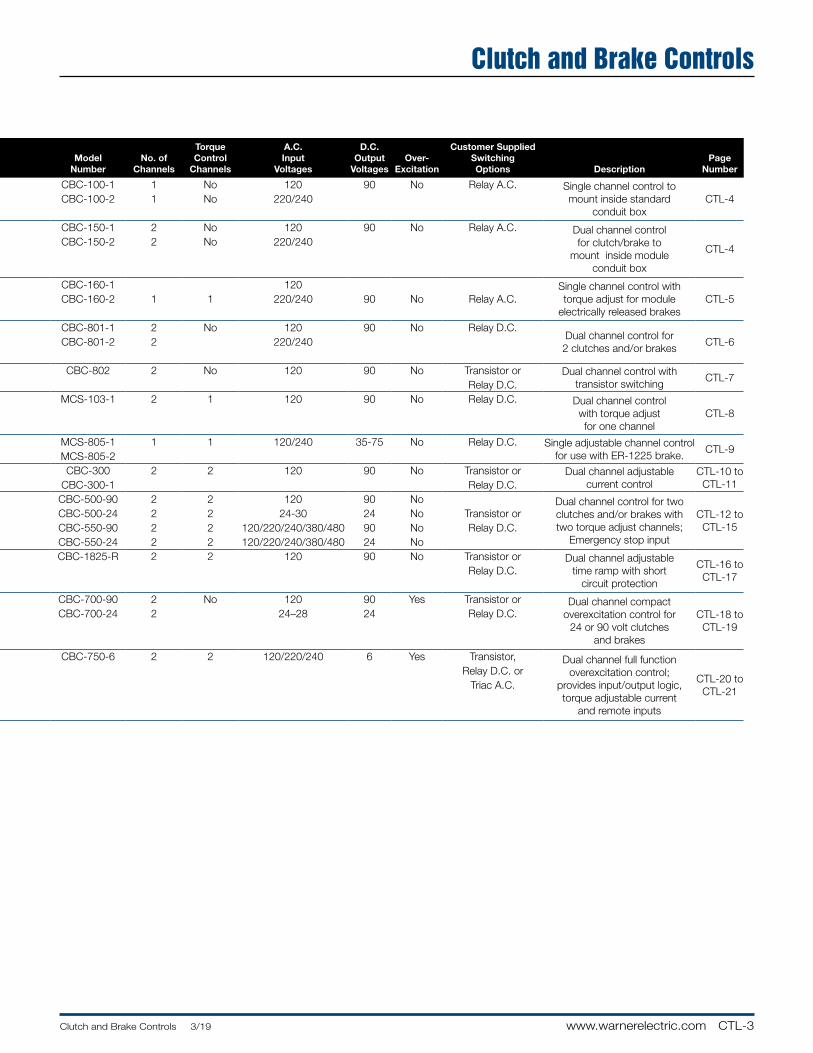
CTL-3Clutch and Brake Controls 3/19 www.warnerelectric.com
ControlType
ModelNumber
No. ofChannels
TorqueControl
Channels
A.C.Input
Voltages
D.C. Output
VoltagesOver-
Excitation
Customer SuppliedSwitchingOptions Description
PageNumber
On-OffConduit Box Mount
CBC-100-1 1 No 120 90 No Relay A .C . Single channel control tomount inside standard
conduit boxCTL-4CBC-100-2 1 No 220/240
CBC-150-1 2 No 120 90 No Relay A .C . Dual channel control for clutch/brake to
mount inside module conduit box
CTL-4CBC-150-2 2 No 220/240
CBC-160-1 120 Single channel control with torque adjust for module
electrically released brakesCTL-5CBC-160-2 1 1 220/240 90 No Relay A .C .
On-Off Octal Socket Mount
CBC-801-1 2 No 120 90 No Relay D .C .Dual channel control for 2 clutches and/or brakes
CTL-6CBC-801-2 2 220/240
CBC-802 2 No 120 90 No Transistor or Dual channel control with transistor switching
CTL-7Relay D .C .
AdjustableTorque
MCS-103-1 2 1 120 90 No Relay D .C . Dual channel controlwith torque adjust for one channel
CTL-8
MCS-805-1 1 1 120/240 35-75 No Relay D .C . Single adjustable channel controlfor use with ER-1225 brake .
CTL-9MCS-805-2CBC-300 2 2 120 90 No Transistor or Dual channel adjustable
current controlCTL-10 to
CTL-11CBC-300-1 Relay D .C .CBC-500-90 2 2 120 90 No Dual channel control for two
clutches and/or brakes withtwo torque adjust channels;
Emergency stop input
CTL-12 to CTL-15
CBC-500-24 2 2 24-30 24 No Transistor orCBC-550-90 2 2 120/220/240/380/480 90 No Relay D .C .CBC-550-24 2 2 120/220/240/380/480 24 No
Adjustable Accel-Decel CBC-1825-R 2 2 120 90 No Transistor or Dual channel adjustable time ramp with short
circuit protection
CTL-16 to CTL-17
Relay D .C .
Overexcitation CBC-700-90 2 No 120 90 Yes Transistor or Dual channel compact overexcitation control for
24 or 90 volt clutches and brakes
CTL-18 to CTL-19
CBC-700-24 2 24–28 24 Relay D .C .
CBC-750-6 2 2 120/220/240 6 Yes Transistor, Dual channel full function overexcitation control;
provides input/output logic, torque adjustable current
and remote inputs
CTL-20 to CTL-21
Relay D .C . orTriac A .C .
Clutch and Brake Controls
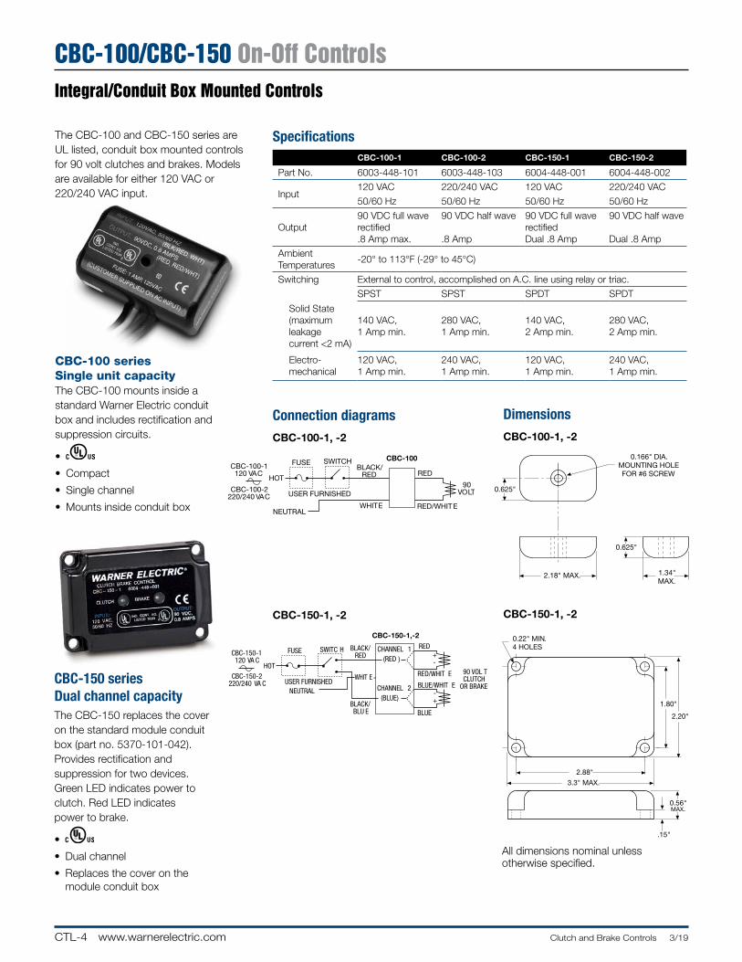
CTL-4 www.warnerelectric.com Clutch and Brake Controls 3/19
CBC-100/CBC-150 On-Off ControlsIntegral/Conduit Box Mounted Controls
Connection diagramsCBC-100-1, -2
CBC-150-1, -2
DimensionsCBC-100-1, -2
CBC-150-1, -2
All dimensions nominal unless otherwise specified .
The CBC-100 and CBC-150 series are UL listed, conduit box mounted controls for 90 volt clutches and brakes . Models are available for either 120 VAC or 220/240 VAC input .
FUSE SWITCHBLACK/
REDHOT
CBC-100-1120 VAC
CBC-100-2220/240 VAC
NEUTRAL
USER FURNISHED
WHITE
CBC-100
RED
RED/WHITE
90VOLT
2.18" MAX. 1.34"MAX.
0.625"
0.166" DIA.MOUNTING HOLEFOR #6 SCREW
0.625"
CBC-150-1120 VA C
CBC-150-2220/240 VA C
HOT
FUSE SWITC H BLACK/RED
CBC-150-1,-2RED
NEUTRALUSER FURNISHED
WHIT E RED/WHIT E
BLACK/BLU E
CHANNEL 1
(BLUE)
BLUE/WHIT E
BLUE
CHANNEL 2
(RED )
90 VOL TCLUTCH
OR BRAKE
+-
-+
2.88"
3.3" MAX.
1.80"
2.20"
0.22" MIN.4 HOLES
0.56"MAX.
.15"
CBC-150 series Dual channel capacityThe CBC-150 replaces the cover on the standard module conduit box (part no . 5370-101-042) . Provides rec ti fi ca tion and sup pres sion for two devices . Green LED indicates power to clutch . Red LED indicates power to brake .
•
• Dual channel
• Replaces the cover on the module conduit box
CBC-100 series Single unit capacityThe CBC-100 mounts inside a standard Warner Electric conduit box and includes rectification and sup pres sion circuits .
•
• Compact
• Single channel
• Mounts inside conduit box
SpecificationsCBC-100-1 CBC-100-2 CBC-150-1 CBC-150-2
Part No . 6003-448-101 6003-448-103 6004-448-001 6004-448-002
Input120 VAC 220/240 VAC 120 VAC 220/240 VAC
50/60 Hz 50/60 Hz 50/60 Hz 50/60 Hz
Output90 VDC full wave rectified .8 Amp max .
90 VDC half wave
.8 Amp
90 VDC full wave rectifiedDual .8 Amp
90 VDC half wave
Dual .8 Amp
AmbientTemperatures
-20° to 113°F (-29° to 45°C)
Switching External to control, accomplished on A .C . line using relay or triac .
SPST SPST SPDT SPDT
Solid State(maximumleakagecurrent <2 mA)
140 VAC, 1 Amp min .
280 VAC, 1 Amp min .
140 VAC, 2 Amp min .
280 VAC, 2 Amp min .
Electro-mechanical
120 VAC, 1 Amp min .
240 VAC, 1 Amp min .
120 VAC, 1 Amp min .
240 VAC, 1 Amp min .
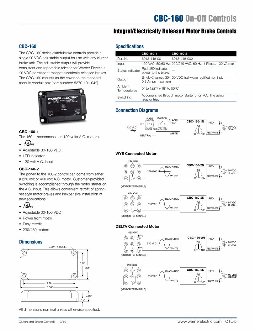
CTL-5Clutch and Brake Controls 3/19 www.warnerelectric.com
CBC-160 On-Off Controls
0.56"
.15"
2.2"
1.8"
0.22" , 4 HOLES
2.88"
3.30"
Integral/Electrically Released Motor Brake Controls
Connection Diagrams
Dimensions
All dimensions nominal unless otherwise specified .
•
•
CBC-160-1N
90 VDCBRAKE
+
-0 100
50RED
RED/WHITE
460 VAC
•
•
CBC-160-2N
230 VAC 90 VDCBRAKE
+
-0 100
50
230 VAC
•
•
CBC-160-2N
230 VAC90 VDCBRAKE
+
-0 100
50
460 VAC
•
•
CBC-160-2N
230 VAC 90 VDCBRAKE
+
-0 100
50
230 VAC
RED
RED/WHITE
BLACK/RED
WHITE
(MOTOR TERMINALS)
RED
RED/WHITE
•
•
CBC-160-2NBLACK/RED
WHITE
230 VAC 90 VDCBRAKE
(MOTOR TERMINALS)
+
-0 100
50T7 T8 T9
T1 T2 T3
T4 T5 T6
T7 T8 T9
T1 T2 T3
T4 T5 T6
T7 T8 T9
T1 T2 T3
T4 T5 T6
T7 T8 T9
T1 T2 T3
T4 T5 T6
RED
RED/WHITE
BLACK/RED
WHITE
(MOTOR TERMINALS)
RED
RED/WHITE
BLACK/RED
WHITE
(MOTOR TERMINALS)
FUSE SWITCHBLACK/
REDHOT120 VAC
NEUTRAL
USER FURNISHED
WHITE
WYE Connected Motor
DELTA Connected Motor
CBC-160The CBC-160 series clutch/brake controls provide a single 90 VDC adjustable output for use with any clutch/brake unit . The adjustable output will provide con sis tent and re peat able release for Warner Elec tric’s 90 VDC per ma nent magnet elec tri cal ly released brakes . The CBC-160 mounts as the cover on the standard module conduit box (part number: 5370-101-042) .
CBC-160-1The 160-1 accommodates 120 volts A .C . motors .
•
• Adjustable 30-100 VDC
• LED indicator
• 120 volt A .C . input
CBC-160-2The power to the 160-2 control can come from either a 230 volt or 460 volt A .C . motor . Cus tom er-provided switching is ac com plished through the motor starter on the A .C . input . This allows convenient retrofit of spring-set style motor brakes and inexpensive in stal la tion of new ap pli ca tions .
•
• Adjustable 30-100 VDC
• Power from motor
• Easy retrofit
• 230/460 motors
SpecificationsCBC-160-1 CBC-160-2
Part No . 6013-448-001 6013-448-002
Input 120 VAC, 50/60 Hz 220/240 VAC, 60 Hz, 1 Phase, 100 VA max .
Status IndicatorRed LED indicatespower to the brake
—
OutputSingle Channel, 30-100 VDC half-wave rectified nominal,0 .8 Amps maximum
Ambient Temperatures
0° to 122°F (-18° to 50°C)
SwitchingAccomplished through motor starter or on A .C . line using relay or triac
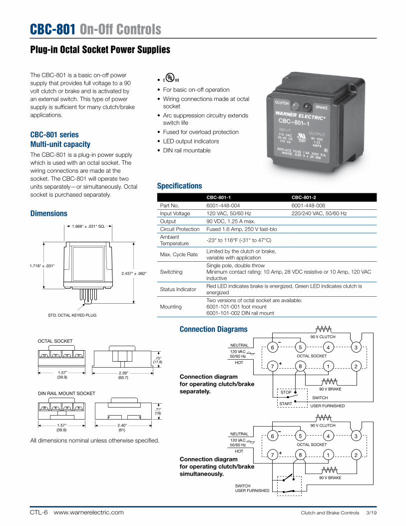
CTL-6 www.warnerelectric.com Clutch and Brake Controls 3/19
CBC-801 On-Off Controls
6 5 4 3
7 8 1 2
NEUTRAL
90 V CLUTCH
OCTAL SOCKET120 VAC50/60 Hz
HOT
STOP
START
90 V BRAKE
SWITCH
USER FURNISHED
6 5 4 3
7 8 1 2
NEUTRAL
90 V CLUTCH
OCTAL SOCKET120 VAC50/60 Hz
HOT
90 V BRAKE
SWITCHUSER FURNISHED
+
+
–
–
1.718" ± .031"
1.968" ± .031" SQ.
2.437" ± .062"
STD. OCTAL KEYED PLUG
1.57"(39.9)
2.39"(60.7)
.70"(17.8)
2.40"(61)
.71"(18)
1.57"(39.9)
OCTAL SOCKET
DIN RAIL MOUNT SOCKET
Plug-in Octal Socket Pow er Supplies
The CBC-801 is a basic on-off power supply that provides full voltage to a 90 volt clutch or brake and is activated by an external switch . This type of power supply is sufficient for many clutch/brake applications .
CBC-801 series Multi-unit capacityThe CBC-801 is a plug-in power supply which is used with an octal socket . The wiring connections are made at the socket . The CBC-801 will operate two units separately—or si mul ta neous ly . Octal socket is purchased separately .
•
• For basic on-off operation
• Wiring connections made at octal socket
• Arc suppression circuitry extends switch life
• Fused for overload protection
• LED output indicators
• DIN rail mountable
Dimensions
Connection Diagrams
All dimensions nominal unless otherwise specified .
Connection diagram for operating clutch/brake separately.
Connection diagram for operating clutch/brake si mul ta neous ly.
SpecificationsCBC-801-1 CBC-801-2
Part No . 6001-448-004 6001-448-006
Input Voltage 120 VAC, 50/60 Hz 220/240 VAC, 50/60 Hz
Output 90 VDC, 1 .25 A max .
Circuit Protection Fused 1 .6 Amp, 250 V fast-blo
Ambient Temperature
-23° to 116°F (-31° to 47°C)
Max . Cycle RateLimited by the clutch or brake, variable with application
SwitchingSingle pole, double throw Minimum contact rating: 10 Amp, 28 VDC resistive or 10 Amp, 120 VAC inductive
Status Indicator Red LED indicates brake is energized, Green LED indicates clutch is energized
MountingTwo versions of octal socket are available:6001-101-001 foot mount6001-101-002 DIN rail mount
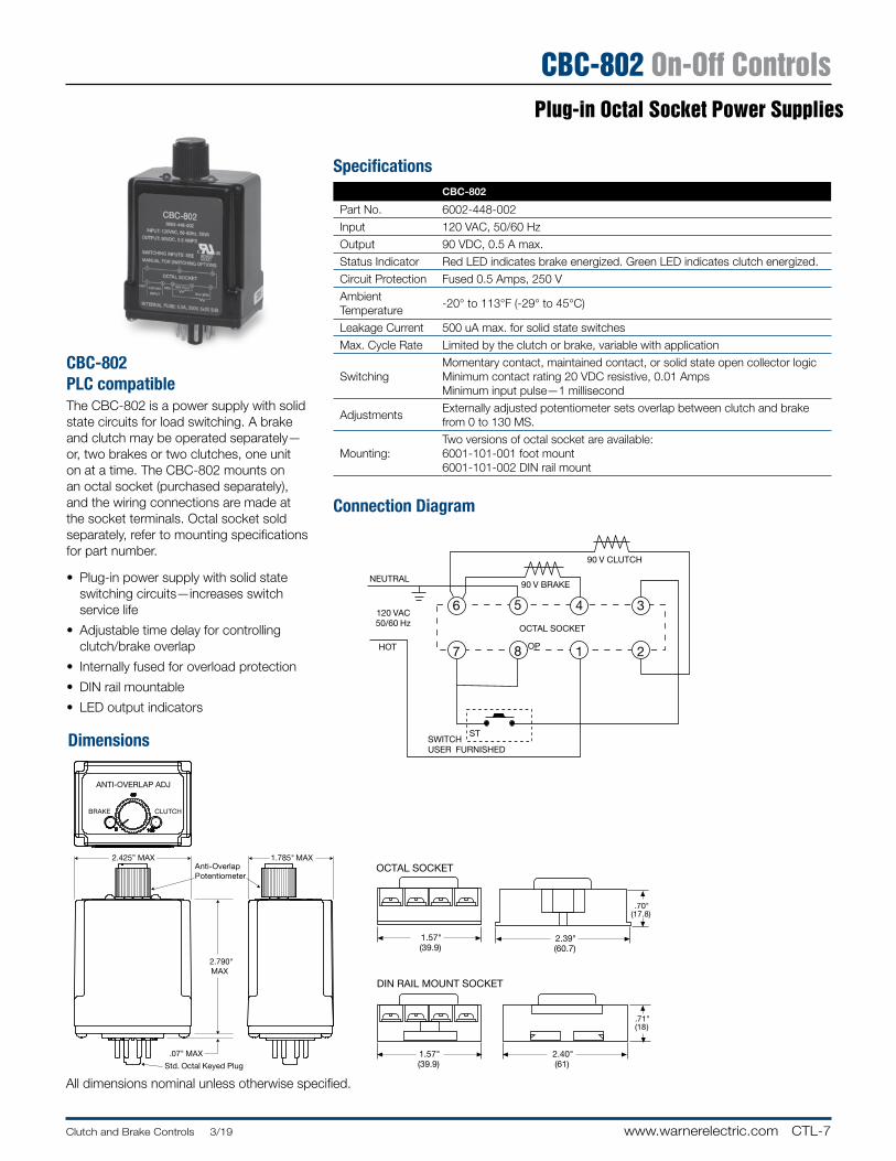
CTL-7Clutch and Brake Controls 3/19 www.warnerelectric.com
CBC-802 On-Off ControlsPlug-in Octal Socket Pow er Supplies
CBC-802 PLC compatibleThe CBC-802 is a power supply with solid state circuits for load switching . A brake and clutch may be operated separately—or, two brakes or two clutches, one unit on at a time . The CBC-802 mounts on an octal socket (pur chased sep a rate ly), and the wiring connections are made at the socket terminals . Octal socket sold separately, refer to mounting specifications for part number .
• Plug-in power supply with solid state switching circuits—increases switch service life
• Adjustable time delay for controlling clutch/brake overlap
• Internally fused for overload protection
• DIN rail mountable
• LED output indicators
Dimensions
Connection Diagram
3.562"
3.75"
.062"
STD. OCTAL KEYED PLUG
1.437"
1.57"(39.9)
2.39"(60.7)
.70"(17.8)
2.40"(61)
.71"(18)
1.57"(39.9)
OCTAL SOCKET
DIN RAIL MOUNT SOCKET
NEUTRAL
OCTAL SOCKET
120 VAC50/60 Hz
HOT
SWITCHUSER FURNISHED
ST
OP
5 3
7 8 1 2
90 V BRAKE
90 V CLUTCH
46
All dimensions nominal unless otherwise specified .
ANTI-OVERLAP ADJ
BRAKE CLUTCH
2.425” MAX
2.790"MAX
.07" MAX
Anti-OverlapPotentiometer
MAX1.785"
Std. Octal Keyed Plug
SpecificationsCBC-802
Part No . 6002-448-002
Input 120 VAC, 50/60 Hz
Output 90 VDC, 0 .5 A max .
Status Indicator Red LED indicates brake energized . Green LED indicates clutch energized .
Circuit Protection Fused 0 .5 Amps, 250 V
Ambient Temperature
-20° to 113°F (-29° to 45°C)
Leakage Current 500 uA max . for solid state switches
Max . Cycle Rate Limited by the clutch or brake, variable with application
SwitchingMomentary contact, maintained contact, or solid state open collector logicMinimum contact rating 20 VDC resistive, 0 .01 AmpsMinimum input pulse—1 millisecond
AdjustmentsExternally adjusted potentiometer sets overlap between clutch and brake from 0 to 130 MS .
Mounting:Two versions of octal socket are available:6001-101-001 foot mount6001-101-002 DIN rail mount
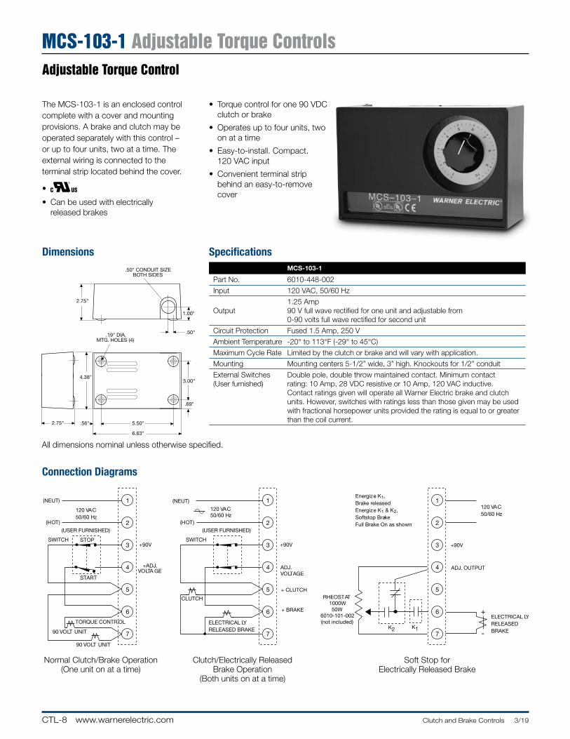
CTL-8 www.warnerelectric.com Clutch and Brake Controls 3/19
MCS-103-1 Adjustable Torque Controls
2.75"
4.38"
.56" 5.50"
6.63"
2.75"
.19" DIA.MTG. HOLES (4)
.50"
1.00"
.50" CONDUIT SIZEBOTH SIDES
3.00"
.69"
1
2
3
4
5
6
7
+
-K1K2
120 VAC50/60 Hz
+90V
ADJ. OUTPUT
RHEOSTAT1000W50W
6010-101-002(not included)
120 VAC50/60 Hz
1
2
3
4
5
6
7
+90V
+ADJ.VOLTA GE
TORQUE CONTR OL
SWITCH
(USER FURNISHED)
(NEUT)
(HOT)
STOP
START
90 VOLT UNIT
90 VOLT UNIT
+ CLUTCH
+ BRAKE
1
2
3
4
5
6
7
+90V
ADJ.VOLTAGE
CLUTCH
ELECTRICAL LYRELEASED BRAKE
SWITCH
120 VAC50/60 Hz
(USER FURNISHED)
(NEUT)
(HOT)
Energize K1,Brake releasedEnergize K1 & K2,Softstop BrakeFull Brake On as shown
ELECTRICAL LYRELEASEDBRAKE
Adjustable Torque Control
The MCS-103-1 is an enclosed control complete with a cover and mounting provisions . A brake and clutch may be operated separately with this control – or up to four units, two at a time . The external wiring is connected to the terminal strip located behind the cover .
•
• Can be used with electrically released brakes
Dimensions
Connection Diagrams
All dimensions nominal unless otherwise specified .
Soft Stop for Electrically Released Brake
Normal Clutch/Brake Op er a tion (One unit on at a time)
Clutch/Electrically Released Brake Operation
(Both units on at a time)
• Torque control for one 90 VDC clutch or brake
• Operates up to four units, two on at a time
• Easy-to-install . Compact . 120 VAC input
• Convenient terminal strip behind an easy-to-remove cover
SpecificationsMCS-103-1
Part No . 6010-448-002
Input 120 VAC, 50/60 Hz
Output1 .25 Amp90 V full wave rectified for one unit and adjustable from 0-90 volts full wave rectified for second unit
Circuit Protection Fused 1 .5 Amp, 250 V
Ambient Temperature -20° to 113°F (-29° to 45°C)
Maximum Cycle Rate Limited by the clutch or brake and will vary with application .
Mounting Mounting centers 5-1/2” wide, 3” high . Knockouts for 1/2” conduit
External Switches(User furnished)
Double pole, double throw maintained contact . Minimum contact rating: 10 Amp, 28 VDC resistive or 10 Amp, 120 VAC inductive . Contact ratings given will operate all Warner Electric brake and clutch units . However, switches with ratings less than those given may be used with fractional horsepower units provided the rating is equal to or greater than the coil current .
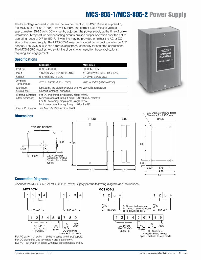
CTL-9Clutch and Brake Controls 3/19 www.warnerelectric.com
MCS-805-1/MCS-805-2 Power Supply
Connection DiagramsConnect the MCS-805-1 or MCS-805-2 Power Supply per the following diagram and instructions:
The DC voltage required to release the Warner Electric ER-1225 Brake is supplied by the MCS-805-1 or MCS-805-2 Power Supply . The correct brake release voltage—approximately 35-75 volts DC—is set by adjusting the power supply at the time of brake installation . Temperature compensating circuits provide proper operation over the entire operating range of 0°F to 150°F . Switching may be provided on either the AC or DC side of the power supply . The MCS-805-1 may be mounted on its back panel or on 1/2” conduit . The MCS-805-2 has a torque adjustment capability for soft stop applications . The MCS-805-2 requires two switching circuits when used for those applications requiring soft engagement .
MCS 805-1
1 2 3 4
1 2 3 4 5 6 7 8 9
1 2 3 4
120 VAC
MCS 805-2
1 2 3 4
1 2 3 4 5 6 7 8 9
1 2 3 4
120 VAC
AC INPUT120/230 VAC
50/60 Hz
230 VAC 230 VAC
– +
Brake DC Switching(Jumper if not used)
S1
S1 S1
S2
GND AC INPUT120/230 VAC
50/60 Hz
– +
BrakeDC Switching
Closed – brake releaseOpen – brake in tq. adj. mode
S1
GND
S1Open – brake engagedClosed – brake released
or tq. adj. mode per S1
0.28 Diameter (4) Mtg HolesClearance for .25" Screw
BACK
0.875 Diameter Knockouts for 0.50 Conduit Both Ends Typical
TOP AND BOTTOM
3.44
2.625
1.125
FRONT
7.125
5.0
SIDE
3.44
0.56
6.0
4.81
5.0
3.750.53
Dimensions
For AC switching, switch may be in series with input supply .For DC switching, use terminals 7 and 8 as shown .DO NOT put switch in series with load on terminals 5 and 6 .
SpecificationsMCS-805-1 MCS-805-2
Part No . 6090-448-006 6090-448-007
Input 115/230 VAC, 50/60 Hz ±10% 115/230 VAC, 50/60 Hz ±10%
Output 0 .4 Amp, 35/75 VDC 0 .4 Amp, 35/75 VDC
Ambient Temperature
-20° to 150°F (-29° to 65°C) -20° to 150°F (-29° to 65°C)
MaximumCycle Rate
Limited by the clutch or brake and will vary with application . Consult factoryfor specifics .
External Switches(User furnished)
For DC switching: single pole, single throw . Minimum contact rating 1 amp, 120 volts DC resistive . For AC switching: single pole, single throw . Minimum contact rating 1 amp, 120 volts AC .
Circuit Protection .75 Amp 250V Slow Blow 3 AG
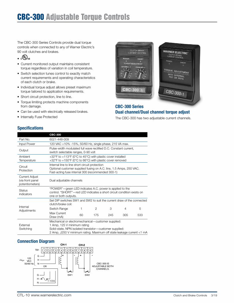
CTL-10 www.warnerelectric.com Clutch and Brake Controls 3/19
CBC-300 Adjustable Torque Controls
Connection Diagram
The CBC-300 Series Controls provide dual torque controls when connected to any of Warner Electric’s 90 volt clutches and brakes .
•
• Current monitored output maintains consistent torque regardless of variation in coil temperature .
• Switch selection tunes control to exactly match current requirements and operating characteristics of each clutch or brake .
• Individual torque adjust allows preset maximum torque tailored to ap pli ca tion re quire ments .
• Short circuit protection, line to line .
• Torque limiting protects machine components from damage .
• Can be used with electrically released brakes .
• Internally Fuse Protected
CBC-300 Series Dual channel/Dual channel torque adjustThe CBC-300 has two adjustable current channels .
1 2 3 4 5 6 7 8 9TB1
120VAC
50/60 Hz
G
H
NOR
G
H
N
CBC-300 ISADJUSTABLE BOTH
CHANNELS.
1-1/2 A
CH-1 CH-2
+ - + -
SW1 SW2 ADJUSTABLEVOLTAGE CHANNEL 1
SpecificationsCBC-300
Part No . 6021-448-009
Input Power 120 VAC +10% -15%, 50/60 Hz, single phase, 215 VA max .
OutputPulse-width modulated full wave rectified D .C . Constant current, switch selectable ranges, 0-90 volt
AmbientTemperature
+32°F to +113°F (0°C to 45°C) with plastic cover installed+32°F to +150°F (0°C to 66°C) with plastic cover removed
CircuitProtection
Internal line to line short circuit protectionOptional customer supplied fusing on A .C . line, 1 .5 Amps, 250 VAC . Fast-acting fuse internal 300 (recommended 300-1)
Current Adjust(via front panelpotentiometers)
Dual adjustable channels
Status indicators
“POWER”—green LED indicates A .C . power is applied to the control . “SHORT”—red LED indicates a short circuit condition exists on one or both outputs .
InternalAdjustments
Set DIP switches SW1 and SW2 to suit the current draw of the connected clutch/brake coil:
Switch Range 1 2 3 4 5
Max Current Draw (mA)
60 175 245 305 533
ExternalSwitching
Mechanical or electromechanical—customer supplied:1 Amp, 125 V minimum ratingSolid-state, NPN isolated transistor—customer supplied:2 Amp, J250 V minimum rating . Maximum off state leakage current <1 mA
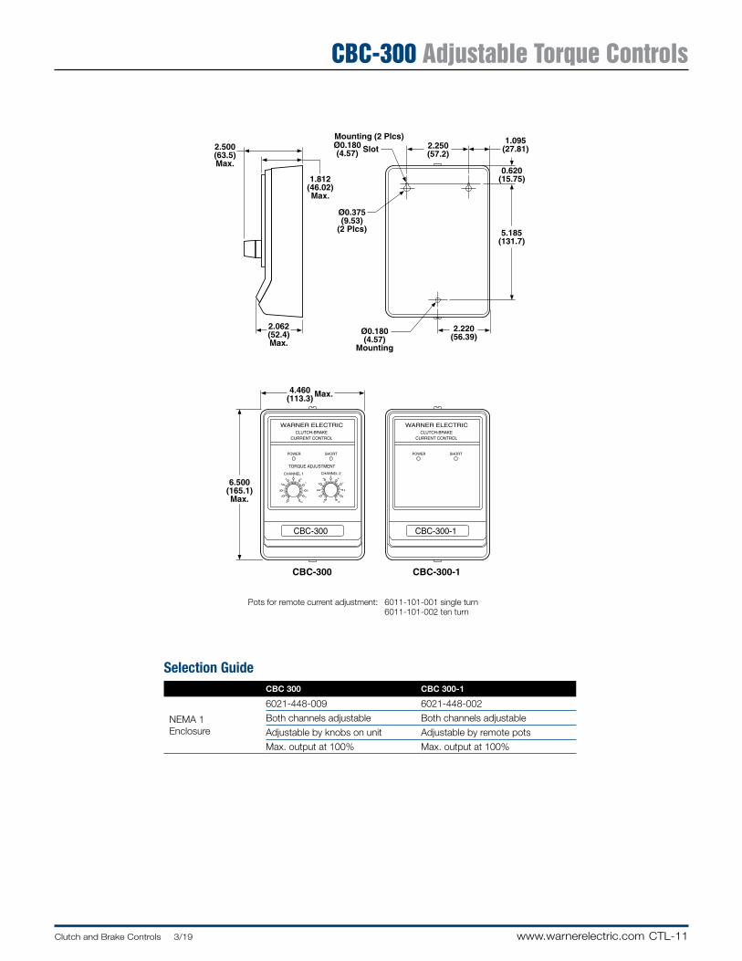
CTL-11Clutch and Brake Controls 3/19 www.warnerelectric.com
CBC-300 Adjustable Torque Controls
Pots for remote current adjustment: 6011-101-001 single turn 6011-101-002 ten turn
SHORTPOWER
WARNER ELECTRICCLUTCH-BRAKE
CURRENT CONTROL
CBC-300-1
SHORTPOWER
WARNER ELECTRICCLUTCH-BRAKE
CURRENT CONTROL
CHANNEL 1
TORQUE ADJUSTMENT
CBC-300
1
2
3
45
6
7
8
9
100
CBC-300-1CBC-300-3
CBC-300CBC-300-2
4.460(113.3) Max.
6.500(165.1)Max.
2.250(57.2)
1.095(27.81)
0.620(15.75)
5.185(131.7)
2.220(56.39)
Ø0.180(4.57)
Mounting
Ø0.375(9.53)
(2 Plcs)
Ø0.180(4.57) Slot
Mounting (2 Plcs)2.500(63.5)Max.
1.812(46.02)Max.
2.062(52.4)Max.
CHANNEL 2
1
2
3
45
6
7
8
9
100
Selection GuideCBC 300 CBC 300-1
NEMA 1Enclosure
6021-448-009 6021-448-002
Both channels adjustable Both channels adjustable
Adjustable by knobs on unit Adjustable by remote pots
Max . output at 100% Max . output at 100%

CTL-12 www.warnerelectric.com Clutch and Brake Controls 3/19
CBC-500 Adjustable Torque ControlsPanel Mounted
CBC-500 series Dual torque adjustable power suppliesThe CBC-500 series is a dual channel ad just able voltage control with optically isolated input switching for 24 and 90 volt electric clutches and brakes . These controls can be set up to energize the two outputs alternately (single) or si mul ta neous ly (dual) . Refer to the Appendix for additional setup and switching in for ma tion .
• Dual adjustable channels
• Optically isolated input switching
• Single or dual channel operation
• Auxiliary 12V supply
• Can be used with electrically released brakes
• Lift off hinge
• Quick-release latches
• Conforms to NEMA Type 13
• European Standard IEC 529, IP65
Enclosure (Optional)
SpecificationsCBC-500-90 CBC-500-24
Part No . 6024-448-003 6024-448-002
Input Voltage 120 VAC 24-30 VAC or VDC
Output Voltage 0-90 VDC 0-24 VDC
Output Current1 Amp/Channel2 Amps Total
5 Amps/Channel5 Amps Total
AuxiliarySupply
12 VDC 250 mA 12 VDC 250 mA
CircuitProtection
Fused2 .5 Amp, 250 V Fast-blo
Fused6 .3 Amp, 250 V Fast-blo
Ambient Temperature
+32° to 122°F (0° to 50°C)
StatusIndicators
Red LED indicates channel is energized .
Adjustments
Two potentiometers for voltage adjustment of channel 1 and channel 2 output from 0 to full rated voltage . Frequency adjustment from 60 to 400 Hz to reduce clutch/brake “Hum” associated with machine frequencies . Jumper for single or dual operation . See Appendix for explanation .
Inputs:3 Optically coupled, 10-30 VDC, 3-9 mA for Channel 1, Channel 2 and Channel 2 override (applies full voltage to channel 1 output)
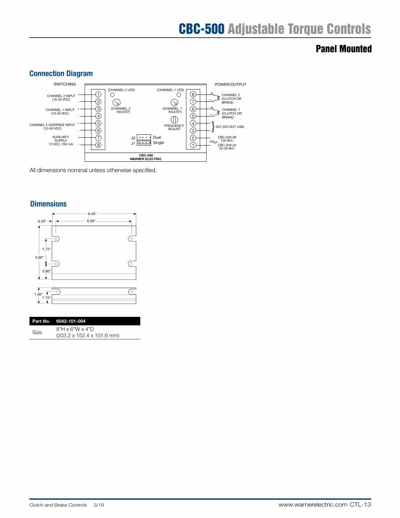
CTL-13Clutch and Brake Controls 3/19 www.warnerelectric.com
CBC-500 Adjustable Torque Controls
CHANNEL 2 OVERRIDE INPUT(10-30 VDC)
CBC-500WARNER ELECTRIC
POWER/OUTPUT
CHANNEL 1 INPUT(10-30 VDC)
CHANNEL 2 INPUT(10-30 VDC)
AUXILIARYSUPPLY
12 VDC, 250 mA
SWITCHING
+
-
+
-
+
-
+
-
1
2
3
4
5
6
7
8
CHANNEL 2(CLUTCH ORBRAKE)
8
7
6
5
4
3
2
1
CHANNEL 1(CLUTCH ORBRAKE)
}
+
-
+
-
N/C (DO NOT USE)
CBC-500-90120 VAC
CBC-500-2424-30 VAC
DualSingle
(CHANNEL 2 LED) (CHANNEL 1 LED)
J2J1
(CHANNEL 1ADJUST)
(CHANNEL 2ADJUST)
FREQUENCYADJUST
• • • •
• • • •
1.75"
0.90"
6.00"0.20"
3.90"
1.15"1.40"
6.40"
Part No. 6042-101-004
Size8”H x 6”W x 4”D(203 .2 x 152 .4 x 101 .6 mm)
Connection Diagram
Dimensions
All dimensions nominal unless otherwise specified .
Panel Mounted
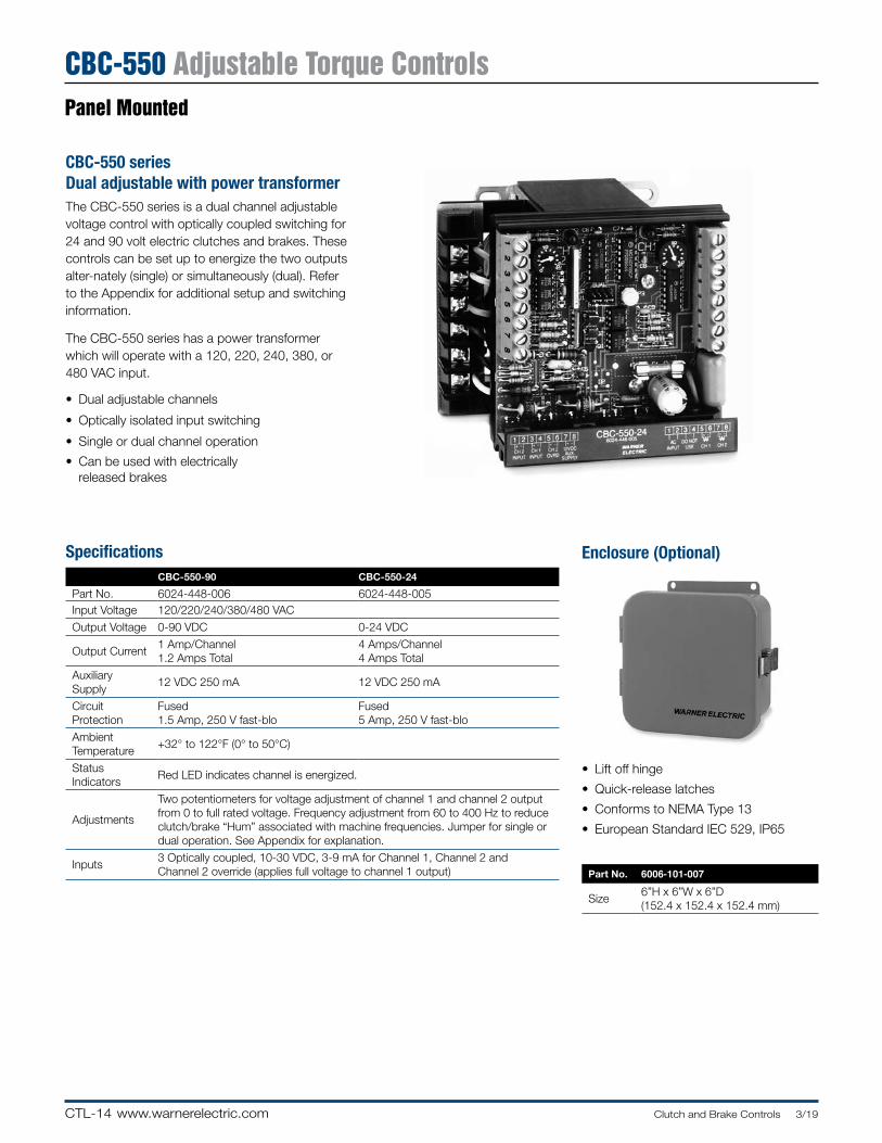
CTL-14 www.warnerelectric.com Clutch and Brake Controls 3/19
CBC-550 Adjustable Torque Controls Panel Mounted
Enclosure (Optional)
• Lift off hinge
• Quick-release latches
• Conforms to NEMA Type 13
• European Standard IEC 529, IP65
Part No. 6006-101-007
Size6”H x 6”W x 6”D (152 .4 x 152 .4 x 152 .4 mm)
CBC-550 series Dual ad just able with power transformerThe CBC-550 series is a dual channel ad just able voltage control with optically coupled switch ing for 24 and 90 volt electric clutches and brakes . These controls can be set up to energize the two outputs al ter -nate ly (single) or si mul ta neous ly (dual) . Refer to the Ap pen dix for additional setup and switch ing information .
The CBC-550 series has a power transformer which will operate with a 120, 220, 240, 380, or 480 VAC input .
• Dual adjustable channels
• Optically isolated input switching
• Single or dual channel operation
• Can be used with electrically released brakes
SpecificationsCBC-550-90 CBC-550-24
Part No . 6024-448-006 6024-448-005Input Voltage 120/220/240/380/480 VAC
Output Voltage 0-90 VDC 0-24 VDC
Output Current1 Amp/Channel1 .2 Amps Total
4 Amps/Channel4 Amps Total
AuxiliarySupply
12 VDC 250 mA 12 VDC 250 mA
CircuitProtection
Fused1 .5 Amp, 250 V fast-blo
Fused5 Amp, 250 V fast-blo
Ambient Temperature
+32° to 122°F (0° to 50°C)
StatusIndicators
Red LED indicates channel is energized .
Adjustments
Two potentiometers for voltage adjustment of channel 1 and channel 2 output from 0 to full rated voltage . Frequency adjustment from 60 to 400 Hz to reduce clutch/brake “Hum” associated with machine frequencies . Jumper for single or dual operation . See Appendix for explanation .
Inputs3 Optically coupled, 10-30 VDC, 3-9 mA for Channel 1, Channel 2 and Channel 2 override (applies full voltage to channel 1 output)
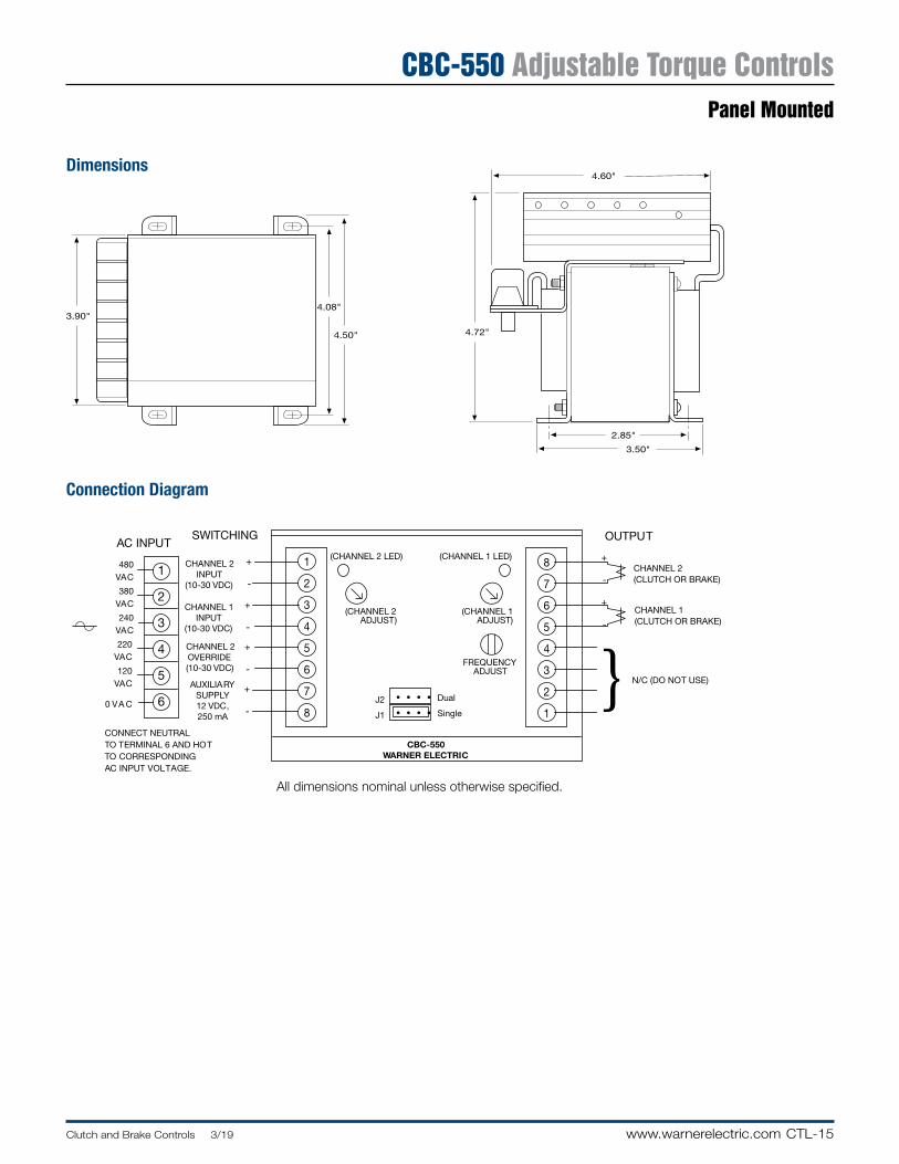
CTL-15Clutch and Brake Controls 3/19 www.warnerelectric.com
CBC-550 Adjustable Torque Controls
CBC-550WARNER ELECTRIC
AC INPUT
CHANNEL 1INPUT
(10-30 VDC)
CHANNEL 2INPUT
(10-30 VDC)
AUXILIARYSUPPLY12 VDC,250 mA
CHANNEL 2OVERRIDE(10-30 VDC)
1
2
3
4
5
6
480V AC
380V AC
240V AC
220V AC
120V AC
0 V A C
+
-
+
-
+
-
+
-
1
2
3
4
5
6
7
8
+
-
+
-
8
7
6
5
4
3
2
1
OUTPUTSWITCHING
}CONNECT NEUTRALTO TERMINAL 6 AND HOTTO CORRESPONDINGAC INPUT VOLT AGE.
CHANNEL 2(CLUTCH OR BRAKE)
CHANNEL 1(CLUTCH OR BRAKE)
N/C (DO NOT USE)
Dual
Single
(CHANNEL 2 LED) (CHANNEL 1 LED)
J2
J1
(CHANNEL 1ADJUST)
(CHANNEL 2ADJUST)
FREQUENCYADJUST
• • • •
• • • •
4.60"
2.85"
3.50"
4.72"4.50"
4.08"3.90"
Dimensions
Connection Diagram
All dimensions nominal unless otherwise specified .
Panel Mounted
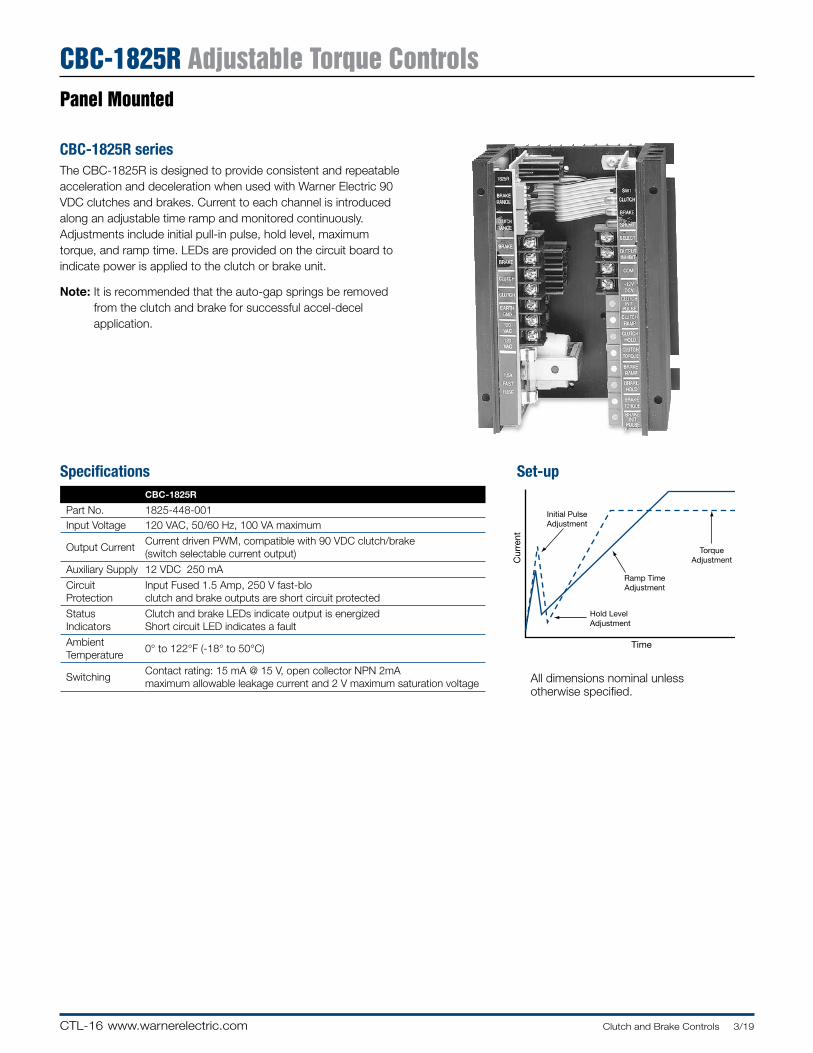
CTL-16 www.warnerelectric.com Clutch and Brake Controls 3/19
CBC-1825R Adjustable Torque Controls Panel Mounted
CBC-1825R seriesThe CBC-1825R is designed to provide consistent and repeatable acceleration and deceleration when used with Warner Electric 90 VDC clutches and brakes . Current to each channel is introduced along an adjustable time ramp and monitored continuously . Adjustments include initial pull-in pulse, hold level, maximum torque, and ramp time . LEDs are provided on the circuit board to indicate power is applied to the clutch or brake unit .
Note: It is recommended that the auto-gap springs be removed from the clutch and brake for successful accel-decel application .
Initial PulseAdjustment
Ramp TimeAdjustment
Hold LevelAdjustment
TorqueAdjustment
Time
Cur
rent
Set-up
All dimensions nominal unless otherwise specified .
SpecificationsCBC-1825R
Part No . 1825-448-001Input Voltage 120 VAC, 50/60 Hz, 100 VA maximum
Output CurrentCurrent driven PWM, compatible with 90 VDC clutch/brake(switch selectable current output)
Auxiliary Supply 12 VDC 250 mA
Circuit Protection
Input Fused 1 .5 Amp, 250 V fast-bloclutch and brake outputs are short circuit protected
Status Indicators
Clutch and brake LEDs indicate output is energizedShort circuit LED indicates a fault
Ambient Temperature
0° to 122°F (-18° to 50°C)
SwitchingContact rating: 15 mA @ 15 V, open collector NPN 2mA maximum allowable leakage current and 2 V maximum saturation voltage
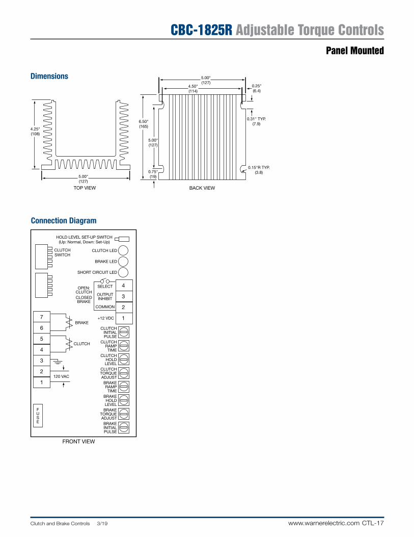
CTL-17Clutch and Brake Controls 3/19 www.warnerelectric.com
CBC-1825R Adjustable Torque Controls
BACK VIEWTOP VIEW
4.25"(108)
5.00"(127)
6.50"(165)
5.00"(127)
5.00"(127)
0.31" TYP.(7.9)
0.15"R TYP.(3.8)
0.25"(6.4)
4.50"(114)
0.75"(19)
CLUTCHSWITCH
+12 VDC
HOLD LEVEL SET-UP SWITCH(Up: Normal, Down: Set-Up)
CLUTCH LED
BRAKE LED
SHORT CIRCUIT LED
OPEN:CLUTCHCLOSEDBRAKE
BRAKE
CLUTCH
120 VAC
SELECT
OUTPUTINHIBIT
COMMON
4
3
2
17
6
5
4
3
2
1
CLUTCHINITIALPULSE
CLUTCHRAMPTIME
CLUTCHHOLDLEVEL
CLUTCHTORQUEADJUSTBRAKERAMPTIME
BRAKEHOLDLEVEL
BRAKETORQUEADJUSTBRAKEINITIALPULSE
FUSE
FRONT VIEW
Connection Diagram
Dimensions
Panel Mounted
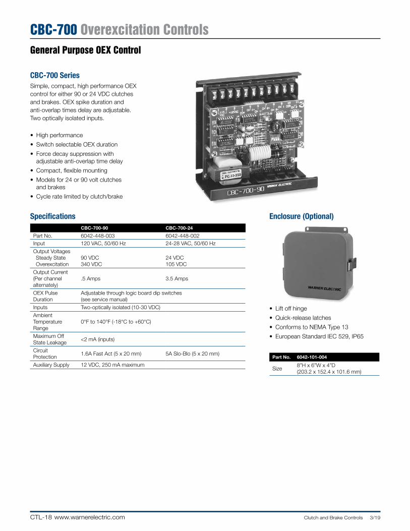
CTL-18 www.warnerelectric.com Clutch and Brake Controls 3/19
CBC-700 Overexcitation ControlsGeneral Purpose OEX Control
Enclosure (Optional)
• Lift off hinge
• Quick-release latches
• Conforms to NEMA Type 13
• European Standard IEC 529, IP65
Part No. 6042-101-004
Size8”H x 6”W x 4”D (203 .2 x 152 .4 x 101 .6 mm)
CBC-700 SeriesSimple, compact, high performance OEX control for either 90 or 24 VDC clutches and brakes . OEX spike duration and anti-overlap times delay are adjustable . Two optically isolated inputs .
• High performance
• Switch selectable OEX duration
• Force decay suppression with adjustable anti-overlap time delay
• Compact, flexible mounting
• Models for 24 or 90 volt clutches and brakes
• Cycle rate limited by clutch/brake
SpecificationsCBC-700-90 CBC-700-24
Part No . 6042-448-003 6042-448-002Input 120 VAC, 50/60 Hz 24-28 VAC, 50/60 Hz
Output Voltages Steady State Overexcitation
90 VDC340 VDC
24 VDC105 VDC
Output Current(Per channelalternately)
.5 Amps 3 .5 Amps
OEX PulseDuration
Adjustable through logic board dip switches(see service manual)
Inputs Two-optically isolated (10-30 VDC)
AmbientTemperatureRange
0°F to 140°F (-18°C to +60°C)
Maximum OffState Leakage
<2 mA (inputs)
CircuitProtection
1 .6A Fast Act (5 x 20 mm) 5A Slo-Blo (5 x 20 mm)
Auxiliary Supply 12 VDC, 250 mA maximum
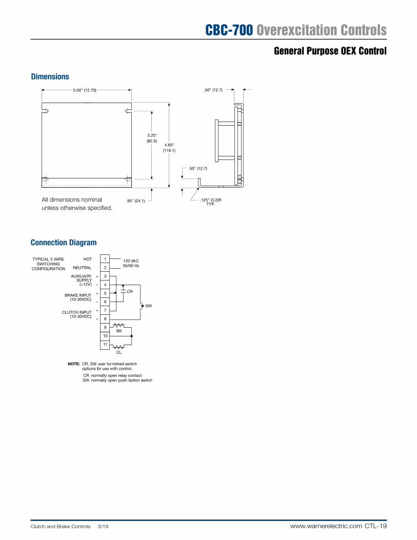
CTL-19Clutch and Brake Controls 3/19 www.warnerelectric.com
CBC-700 Overexcitation Controls
1
2
3
4
5
6
7
8
9
10
11
120 VAC50/60 Hz
SW
BK
CL
CR
CR, SW user furnished switchoptions for use with control.
normally open relay contact normally open push button switch
NOTE:
CRSW
TYPICAL 3 WIRESWITCHING
CONFIGURATION
HOT
NEUTRAL
+
–
+
–
+
–
AUXILIARYSUPPLY
(+12V)
BRAKE INPUT(10-30VDC)
CLUTCH INPUT(10-30VDC)
5.00" (12.70)
3.25"(82.5)
4.65"(118.1)
.95" (24.1)
.50" (12.7)
.125" (3.2)RTYP.
.50" (12.7)
Dimensions
Connection Diagram
All dimensions nominal unless otherwise specified .
General Purpose OEX Control
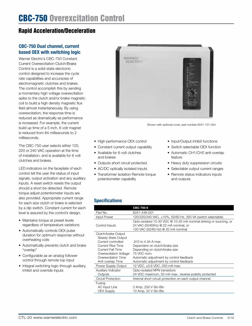
CTL-20 www.warnerelectric.com Clutch and Brake Controls 3/19
CBC-750 Overexcitation ControlRapid Acceleration/Deceleration
• High performance OEX control
• Constant current output capability
• Available for 6 volt clutches and brakes
• Outputs short circuit protected .
• AC/DC optically isolated inputs
• Transformer isolation Remote torque potentiometer capability
• Input/Output inhibit functions
• Switch selectable OEX function
• Automatic CH1/CH2 anit-overlap feature
• Heavy duty suppression circuits
• Selectable output current ranges
• Remote status indicators inputs and outputs
CBC-750 Dual channel, current based OEX with switch ing logicWarner Electric’s CBC-750 Constant Current Overexcitation Clutch/Brake Control is a solid-state electronic control designed to increase the cycle rate capabilities and accuracies of electromagnetic clutches and brakes . The control accomplish this by sending a momentary high voltage overexcitation spike to the clutch and/or brake magnetic coil to build a high density magnetic flux field almost instantaneously . By using overexcitation, the response time is reduced as dramatically as performance is increased . For example, the current build up time of a 5 inch, 6 volt magnet is reduced from 84 milliseconds to 2 milliseconds .
The CBC-750 user selects either 120, 220 or 240 VAC operation at the time of installation, and is available for 6 volt clutches and brakes .
LED indicators on the faceplate of each control tell the user the status of input signals, output activation and any auxiliary inputs . A reset switch resets the output should a short be detected . Remote torque adjust potentiometer inputs are also provided . Appropriate current range for each size clutch or brake is selected by a dip switch . Constant current for each level is assured by the control’s design .
• Maintains torque at preset levels regardless of temperature variations
• Automatically controls OEX pulse duration for optimum response without overheating coils
• Automatically prevents clutch and brake “overlap”
• Configurable as an analog follower control through remote top input
• Integral switching logic through auxiliary, inhibit and override inputs
Shown with optional cover, part number 6041-101-004
SpecificationsCBC-750-6
Part No . 6041-448-001Input Power 120/220/240 VAC, ±10%, 50/60 Hz, 350 VA (switch selectable)
Control InputsOpto-isolated 10-30 VDC @ 10-35 mA nominal sinking or sourcing, or24 VAC (50/60Hz) @ 22 mA nominal, or 120 VAC (50/60 Hz) @ 20 mA nominal
Clutch/brake OutputSteady State OutputCurrent controlledCurrent Rise TimeCurrent Fall TimeOverexcitation VoltageOverexcitation TimeAnti-overlap Time
.910 to 4 .34 A max .Dependent on clutch/brake sizeDepending on clutch/brake size75 VDC nom .Automatic adjustment by control feedbackAutomatic adjustment by control feedback
Power Supply Output 12 VDC, ±0 .6 VDC, 250 mA max .Auxiliary Indicator
OutputsOpto-isolated NPN transistors24 VDC maximum, 20 mA max ., reverse polarity protected
Circuit Protection Internal short circuit protection on each output channel .Fusing
AC Input LineOEX Supply
2 Amp, 250 V Slo-Blo10 Amp, 32 V Slo-Blo
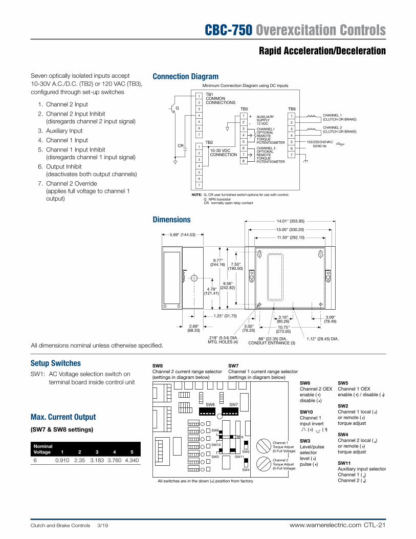
CTL-21Clutch and Brake Controls 3/19 www.warnerelectric.com
CBC-750 Overexcitation ControlsRapid Acceleration/Deceleration
1
2
3
4
5
6
7
120/220/240 VAC50/60 Hz
CHANNEL 1(CLUTCH OR BRAKE)
CHANNEL 2(CLUTCH OR BRAKE)
CR
Minimum Connection Diagram using DC inputs.
1
2
3
4
5
6
7
TB1COMMONCONNECTIONS
TB2
10-30 VDC CONNECTION
1
2
3
4
5
6
7
8
TB5Q
1
2
3
4
5
6
7
TB6
Q, CR user furnished switch options for use with control. NPN transistor
normally open relay contact
NOTE:QCR
AUXILIARYSUPPLY12 VDC
CHANNEL1OPTIONALREMOTETORQUEPOTENTIOMETER
CHANNEL 2OPTIONALREMOTETORQUEPOTENTIOMETER
+
-
SW8
SW6
SW10
SW3 SW11
SW5
SW2
SW4
SW7
SW5Channel 1 OEXenable ( ) / disable ( )
SW2Channel 1 local ( )or remote ( )torque adjust
SW4Channel 2 local ( )or remote ( )torque adjust
SW11Auxiliary input selectorChannel 1 ( )Channel 2 ( )
SW6Channel 2 OEXenable ( )disable ( )
SW10Channel 1 input invert ( ) ( )
SW3Level/pulse selector level ( )pulse ( )
SW8Channel 2 current range selector(settings in diagram below)
SW7Channel 1 current range selector(settings in diagram below)
All switches are in the down ( ) position from factory
Channel 1Torque Adjust(0-Full Voltage)
Channel 2Torque Adjust(0-Full Voltage)
5.69" (144.53)
14.01" (355.85)
13.00" (330.20)
11.50" (292.10)
7.50"(190.50)
9.56"(242.82)
9.77"(244.16)
4.78"(121.41)
10.75"(273.05)
3.09"(78.49)
1.12" (28.45) DIA .
1.25" (31.75)
2.69"(68.33)
.88" (22.35) DIA .CONDUIT ENTRANCE (3)
3.16"(80.26)
3.00"(76.20)
.218" (5.54) DIA .MTG. HOLES (4)
Dimensions
Connection Diagram
Setup SwitchesSW1: AC Voltage selection switch on terminal board inside control unit
Max. Current Output(SW7 & SW8 settings)
Nominal Voltage 1 2 3 4 5
6 0 .910 2 .35 3 .183 3 .760 4 .340
Seven optically isolated inputs accept 10-30V A .C ./D .C . (TB2) or 120 VAC (TB3), configured through set-up switches
1 . Channel 2 Input
2 . Channel 2 Input Inhibit (disregards channel 2 input signal)
3 . Auxiliary Input
4 . Channel 1 Input
5 . Channel 1 Input Inhibit (disregards channel 1 input signal)
6 . Output Inhibit (deactivates both output channels)
7 . Channel 2 Override (applies full voltage to channel 1 output)
All dimensions nominal unless otherwise specified .
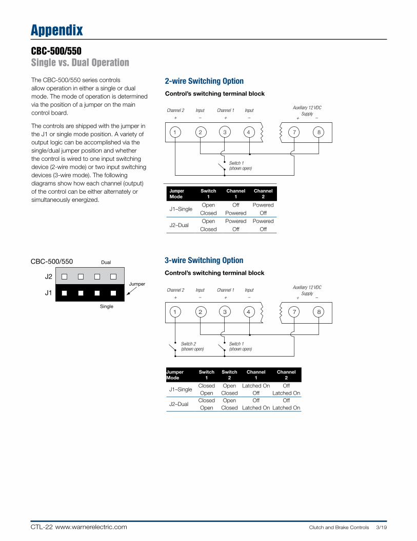
CTL-22 www.warnerelectric.com Clutch and Brake Controls 3/19
AppendixCBC-500/550 Single vs. Dual Operation
3-wire Switching OptionControl’s switching terminal block
Jumper Mode
Switch 1
Switch 2
Channel 1
Channel 2
J1–SingleClosed Open Latched On OffOpen Closed Off Latched On
J2–DualClosed Open Off OffOpen Closed Latched On Latched On
2-wire Switching OptionControl’s switching terminal block
Jumper Mode
Switch 1
Channel 1
Channel 2
J1–SingleOpen Off Powered
Closed Powered Off
J2–DualOpen Powered Powered
Closed Off Off
The CBC-500/550 series controls allow operation in either a single or dual mode . The mode of operation is de ter mined via the position of a jumper on the main control board .
The controls are shipped with the jumper in the J1 or single mode position . A variety of output logic can be ac com plished via the single/dual jumper position and whether the control is wired to one input switching device (2-wire mode) or two input switching devices (3-wire mode) . The following diagrams show how each channel (output) of the control can be either al ter nate ly or si mul ta neous ly en er gized .
J2
J1
Dual
Jumper
Single
J1
DualSingle
CBC-400/450
CBC-500/550
Channel 2 Input Channel 1 Input
+ – + –
Switch 1(shown open)
Auxiliary 12 VDCSupply
+ –
1 2 3 4 7 8
Channel 2 Input Channel 1 Input
+ – + –
Switch 1(shown open)
Switch 2(shown open)
Auxiliary 12 VDCSupply
+ –
1 2 3 4 7 8
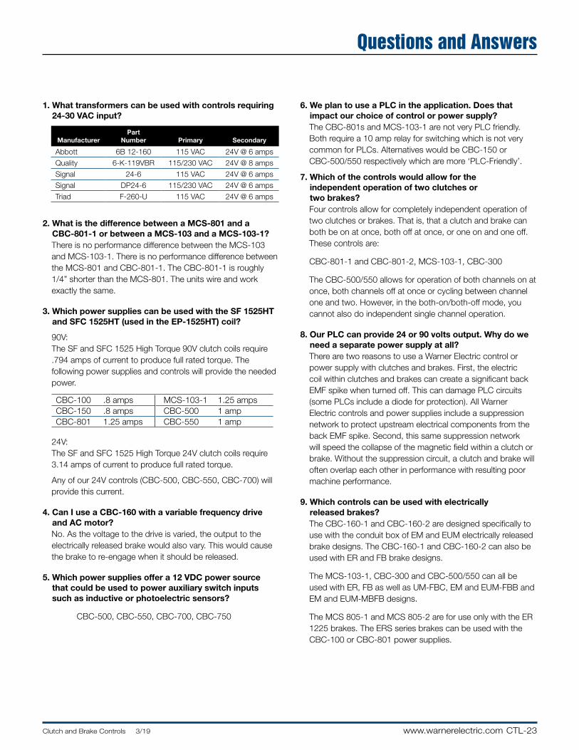
CTL-23Clutch and Brake Controls 3/19 www.warnerelectric.com
Questions and Answers
1. What transformers can be used with con trols requiring 24-30 VAC input?
ManufacturerPart
Number Pri ma ry Secondary
Abbott 6B 12-160 115 VAC 24V @ 6 amps
Quality 6-K-119VBR 115/230 VAC 24V @ 8 amps
Signal 24-6 115 VAC 24V @ 6 amps
Signal DP24-6 115/230 VAC 24V @ 6 amps
Triad F-260-U 115 VAC 24V @ 6 amps
2. What is the difference between a MCS-801 and a CBC-801-1 or between a MCS-103 and a MCS-103-1?
There is no performance difference between the MCS-103 and MCS-103-1 . There is no per for mance difference between the MCS-801 and CBC-801-1 . The CBC-801-1 is roughly 1/4” shorter than the MCS-801 . The units wire and work exactly the same .
3. Which power supplies can be used with the SF 1525HT and SFC 1525HT (used in the EP-1525HT) coil?
90V: The SF and SFC 1525 High Torque 90V clutch coils require
.794 amps of current to produce full rated torque . The following power supplies and controls will provide the needed power . CBC-100 .8 amps MCS-103-1 1 .25 ampsCBC-150 .8 amps CBC-500 1 ampCBC-801 1 .25 amps CBC-550 1 amp
24V: The SF and SFC 1525 High Torque 24V clutch coils require
3 .14 amps of current to produce full rated torque .
Any of our 24V controls (CBC-500, CBC-550, CBC-700) will provide this current .
4. Can I use a CBC-160 with a variable frequency drive and AC motor?
No . As the voltage to the drive is varied, the output to the electrically released brake would also vary . This would cause the brake to re-engage when it should be released .
5. Which power supplies offer a 12 VDC power source that could be used to power auxiliary switch inputs such as inductive or photoelectric sensors?
CBC-500, CBC-550, CBC-700, CBC-750
6. We plan to use a PLC in the application. Does that impact our choice of control or power supply?
The CBC-801s and MCS-103-1 are not very PLC friendly . Both require a 10 amp relay for switching which is not very common for PLCs . Alternatives would be CBC-150 or CBC-500/550 respectively which are more ‘PLC-Friendly’ .
7. Which of the controls would allow for the independent operation of two clutches or two brakes?
Four controls allow for completely independent operation of two clutches or brakes . That is, that a clutch and brake can both be on at once, both off at once, or one on and one off . These controls are:
CBC-801-1 and CBC-801-2, MCS-103-1, CBC-300
The CBC-500/550 allows for operation of both channels on at once, both channels off at once or cycling between channel one and two . However, in the both-on/both-off mode, you cannot also do independent single channel operation .
8. Our PLC can provide 24 or 90 volts output. Why do we need a separate power supply at all?
There are two reasons to use a Warner Electric control or power supply with clutches and brakes . First, the electric coil within clutches and brakes can create a significant back EMF spike when turned off . This can damage PLC circuits (some PLCs include a diode for protection) . All Warner Electric controls and power supplies include a suppression network to protect upstream electrical components from the back EMF spike . Second, this same suppression network will speed the collapse of the magnetic field within a clutch or brake . Without the suppression circuit, a clutch and brake will often overlap each other in performance with resulting poor machine performance .
9. Which controls can be used with electrically released brakes?
The CBC-160-1 and CBC-160-2 are designed specifically to use with the conduit box of EM and EUM electrically released brake designs . The CBC-160-1 and CBC-160-2 can also be used with ER and FB brake designs .
The MCS-103-1, CBC-300 and CBC-500/550 can all be used with ER, FB as well as UM-FBC, EM and EUM-FBB and EM and EUM-MBFB designs .
The MCS 805-1 and MCS 805-2 are for use only with the ER 1225 brakes . The ERS series brakes can be used with the CBC-100 or CBC-801 power supplies .
CTL-24 www.warnerelectric.com Clutch and Brake Controls 3/19
Ordering Information
CBC-100-1 ........................................................................ 6003-448-101 .............................CTL-4CBC-100-2 ........................................................................ 6003-448-103 .............................CTL-4MCS-103-1 ........................................................................ 6010-448-002 .............................CTL-8CBC-150-1 ........................................................................ 6004-448-001 .............................CTL-4CBC-150-2 ........................................................................ 6004-448-002 .............................CTL-4CBC-160-1 ........................................................................ 6013-448-001 .............................CTL-5CBC-160-2 ........................................................................ 6013-448-002 .............................CTL-5
CBC-300 ............................................................................ 6021-448-009 .............CTL-10, CTL-11CBC-300-1 ........................................................................ 6021-448-002 ...........................CTL-11
CBC-500-24 ...................................................................... 6024-448-002 ...........................CTL-12CBC-500-90 ...................................................................... 6024-448-003 ...........................CTL-12CBC-550-24 ...................................................................... 6024-448-005 ...........................CTL-14CBC-550-90 ...................................................................... 6024-448-006 ...........................CTL-14
CBC-1825R ....................................................................... 1825-448-001 ...........................CTL-16
CBC-700-24 ...................................................................... 6042-448-002 ...........................CTL-18 CBC-700-90 ...................................................................... 6042-448-003 ...........................CTL-18CBC-750-6 ........................................................................ 6041-448-001 ...........................CTL-20
CBC-801-1 ........................................................................ 6001-448-004 .............................CTL-6CBC-801-2 ........................................................................ 6001-448-006 .............................CTL-6
Octal Socket, Foot Mount .................................................. 6001-101-001 .................CTL-6, CTL-7Octal Socket, DIN Rail Mount ............................................. 6001-101-002 .................CTL-6, CTL-7
CBC-802 ............................................................................ 6002-448-002 .............................CTL-7
Optional Enclosure: CBC-500, CBC-700 ........................... 6042-101-004 .............CTL-12, CTL-18Optional Enclosure: CBC-550 ............................................ 6006-101-007 ...........................CTL-14
MCS-805-1 ........................................................................ 6090-448-006 .............................CTL-9MCS-805-2 ........................................................................ 6090-448-007 .............................CTL-9
Model Part Number Page

PN-1www.warnerelectric.comP-8587-WE 3/19
Part Numbers Ordering Information PN
PN-2 www.warnerelectric.com P-8587-WE 3/19
Electro Brakes - EBDescription Model Part No. Voltage Pg. No.
EB-375 5380-170-005 6EB-375-1/2 5380-170-006 24 A-10
5380-170-004 905380-170-003 6
EB-375-5/8 5380-170-007 24 A-105380-170-002 90
EB-475 5381-170-003 6EB-475 5381-170-004 24 A-10
5381-170-002 90EB-650 5382-170-003 6
EB-650 5382-170-005 24 A-105382-170-002 90
EB-825 5383-170-002 6EB-825 5383-170-004 24 A-10
5383-170-005 90EB-1000 5384-170-003 6
EB-1000 5384-170-005 24 A-105384-170-002 90
EB-1225 5385-170-003 6EB-1225 5385-170-005 24 A-10
5385-170-002 90
Adapters for Electro BrakesDescription Part No. Pg. No.
375-3/8 5380-101-005 A-14375-7/8 5380-101-004 A-14475-1-1/8 5381-101-003 A-14650-1-3/8 5382-101-003 A-14650-1-5/8 5382-101-002 A-141000-1-5/8 5384-101-008 A-141000-1-7/8 5384-101-007 A-141000-2-1/8 5384-101-010 A-141225-2-1/8 5385-101-008 A-141225-2-3/8 5383-101-007 A-14
Bushings for Electro BrakesDescription Model Part No.
1008 Specify Bore Size180-0410 to 180-0418 B-3
1310 Specify Bore Size180-0421 to 180-0435 B-3
H-1, H-2 Specify Bore Size180-0002 to 180-0018 B-2
1615 Specify Bore Size180-0131 to 180-0149 B-2
2517 Specify Bore Size180-0185 to 180-0217 B-3
Electro Clutches - ECDescription Model Part No. Voltage Pg. No.
EC-375 5180-271-006 6EC-375-1/2 5180-271-004 24 A-4
5180-271-009 905180-271-002 6
EC-375-5/8 5180-271-008 24 A-45180-271-005 90
EC-475 5181-271-033 6EC-475-5/8 5181-271-037 24 A-4
5181-271-036 905181-271-032 6
EC-475-3/4 5181-271-038 24 A-45181-271-034 905181-271-031 6
EC-475-7/8 5181-271-039 24 A-45181-271-035 90
EC-650 5281-271-004 6EC-650-1 5281-271-018 24 A-4
5281-271-007 905281-271-002 6
EC-650-1-1/8 5281-271-019 24 A-45281-271-005 905281-271-009 6
EC-650-1-1/4 5281-271-020 24 A-45281-271-008 905281-271-003 6
EC-650-1-3/8 5281-271-016 24 A-45281-271-006 90
EC-825 5282-271-002 6EC-825-1-1/8 5282-271-008 24 A-4
5282-271-011 905282-271-003 6
EC-825-1-1/4 5282-271-009 24 A-45282-271-012 905282-271-004 6
EC-825-1-3/8 5282-271-010 24 A-45282-271-013 90
EC-1000 5283-271-002 6EC-1000-1-3/8 5283-271-010 24 A-4
5283-271-003 90EC-1000-1-1/2 5283-271-012 24 A-4
5283-271-013 905283-271-004 6
EC-1000-1-5/8 5283-271-011 24 A-45283-271-005 90
EC-1225 5284-271-008 6EC-1225-1-5/8 5284-271-013 24 A-4
5284-271-010 905284-271-002 6
EC-1225-1-7/8 5284-271-014 24 A-45284-271-003 905284-271-004 6
EC-1225-2-1/8 5284-271-015 24 A-45284-271-005 90
Shaft Mounted Units
Part Numbers Ordering Information
PN-3www.warnerelectric.comP-8587-WE 3/19
AT Brakes - ATBDescription Model Part No. Voltage Pg. No.
ATB-25 5191-170-002 6ATB-25-1/2 5191-170-010 24 A-23
5191-170-003 905191-170-004 6
ATB-25-5/8 5191-170-011 24 A-235191-170-005 905191-170-006 6
ATB-25-3/4 5191-170-012 24 A-235191-170-007 905191-170-008 6
ATB-25-7/8 5191-170-013 24 A-235191-170-009 90
ATB-55 5192-170-002 6ATB-55-3/4 5192-170-010 24 A-23
5192-170-003 905192-170-004 6
ATB-55-7/8 5192-170-011 24 A-235192-170-005 905192-170-006 6
ATB-55-1 5192-170-012 24 A-235192-170-007 905192-170-008 6
ATB-55-1-1/8 5192-170-013 24 A-235192-170-009 90
ATB-115 5193-170-002 6ATB-115-1-1/8 5193-170-010 24 A-23
5193-170-003 905193-170-004 6
ATB-115-1-1/4 5193-170-011 24 A-235193-170-005 905193-170-006 6
ATB-115-1-3/8 5193-170-012 24 A-235193-170-007 905193-170-008 6
ATB-115-1-1/2 5193-170-013 24 A-235193-170-009 90
AT Clutches - ATCDescription Model Part No. Voltage Pg. No.
ATC-25 5161-271-002 6ATC-25-1/2 5161-271-010 24 A-20
5161-271-003 905161-271-004 6
ATC-25-5/8 5161-271-011 24 A-205161-271-005 905161-271-006 6
ATC-25-3/4 5161-271-012 24 A-205161-271-007 905161-271-008 6
ATC-25-7/8 5161-271-013 24 A-205161-271-009 90
ATC-55 5162-271-002 6ATC-55-3/4 5162-271-010 24 A-20
5162-271-003 905162-271-004 6
ATC-55-7/8 5162-271-011 24 A-205162-271-005 905162-271-006 6
ATC-55-1 5162-271-012 24 A-205162-271-007 905162-271-008 6
ATC-55-1-1/8 5162-271-013 24 A-205162-271-009 90
ATC-115 5163-271-002 6ATC-115-1-1/8 5163-271-010 24 A-20
5163-271-003 905163-271-004 6
ATC-115-1-1/4 5163-271-011 24 A-205163-271-005 905163-271-006 6
ATC-115-1-3/8 5163-271-012 24 A-205163-271-007 905163-271-008 6
ATC-115-1-1/2 5163-271-013 24 A-205163-271-009 90
Stationary Field Clutches - SFPDescription Model Part No. Voltage Pg. No.
SFP-180 SFP-180-1/4 SFP180-14-24 24SFP-180-5/16 SFP180-516-24 24 A-27SFP-180-3/8 SFP180-38-24 24SFP-180-1/4 SFP180-14-90 90SFP-180-5/16 SFP180-516-90 90 A-27SFP-180-3/8 SFP180-38-90 90
SFP-250 5103-271-002 6SFP-250-3/8 5103-271-006 24 A-26
5103-271-010 905103-271-003 6
SFP-250-7/16 5103-271-007 24 A-265103-271-011 905103-271-004 6
SFP-250-1/2 5103-271-008 24 A-265103-271-012 905103-271-005 6
SFP-250-5/8 5103-271-009 24 A-265103-271-013 90
SFP-325 SFP-325-1/2 SFP325-12-24 24SFP325-12-90 90 A-28
Description Model Part No. Voltage Pg. No.
SFP-400 5104-271-006 6SFP-400-1/2 5104-271-016 24 A-26
5104-271-021 905104-271-007 6
SFP-400-5/8 5104-271-017 24 A-265104-271-022 905104-271-008 6
SFP-400-3/4 5104-271-018 24 A-265104-271-023 905104-271-009 6
SFP-400-7/8 5104-271-019 24 A-265104-271-024 905104-271-010 6
SFP-400-1 5104-271-020 24 A-265104-271-025 90
Shaft Mounted Units
Part Numbers Ordering Information

PN-4 www.warnerelectric.com P-8587-WE 3/19
Notes

I-1www.warnerelectric.comP-8587-WE 3/19
INDEX
I
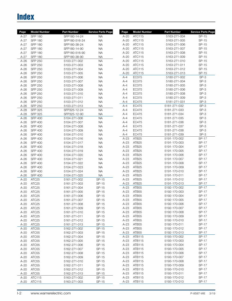
I-2 www.warnerelectric.com P-8587-WE 3/19
Index
Page Model Number Part Number Service Parts Page
A-27 SFP 180 SFP180-14-24 NAA-27 SFP 180 SFP180-516-24 NAA-27 SFP 180 SFP180-38-24 NAA-27 SFP 180 SFP180-14-90 NAA-27 SFP 180 SFP180-516-90 NAA-27 SFP 180 SFP180-38-90 NAA-26 SFP 250 5103-271-002 NAA-26 SFP 250 5103-271-003 NAA-26 SFP 250 5103-271-004 NAA-26 SFP 250 5103-271-005 NAA-26 SFP 250 5103-271-006 NAA-26 SFP 250 5103-271-007 NAA-26 SFP 250 5103-271-008 NAA-26 SFP 250 5103-271-009 NAA-26 SFP 250 5103-271-010 NAA-26 SFP 250 5103-271-011 NAA-26 SFP 250 5103-271-012 NAA-26 SFP 250 5103-271-013 NAA-28 SFP 325 SFP325-12-24 NAA-28 SFP 325 SFP325-12-90 NAA-26 SFP 400 5104-271-006 NAA-26 SFP 400 5104-271-007 NAA-26 SFP 400 5104-271-008 NAA-26 SFP 400 5104-271-009 NAA-26 SFP 400 5104-271-010 NAA-26 SFP 400 5104-271-016 NAA-26 SFP 400 5104-271-017 NAA-26 SFP 400 5104-271-018 NAA-26 SFP 400 5104-271-019 NAA-26 SFP 400 5104-271-020 NAA-26 SFP 400 5104-271-021 NAA-26 SFP 400 5104-271-022 NAA-26 SFP 400 5104-271-023 NAA-26 SFP 400 5104-271-024 NAA-26 SFP 400 5104-271-025 NAA-20 ATC25 5161-271-002 SP-15A-20 ATC25 5161-271-003 SP-15A-20 ATC25 5161-271-004 SP-15A-20 ATC25 5161-271-005 SP-15A-20 ATC25 5161-271-006 SP-15A-20 ATC25 5161-271-007 SP-15A-20 ATC25 5161-271-008 SP-15A-20 ATC25 5161-271-009 SP-15A-20 ATC25 5161-271-010 SP-15A-20 ATC25 5161-271-011 SP-15A-20 ATC25 5161-271-012 SP-15A-20 ATC25 5161-271-013 SP-15A-20 ATC55 5162-271-002 SP-15A-20 ATC55 5162-271-003 SP-15A-20 ATC55 5162-271-004 SP-15A-20 ATC55 5162-271-005 SP-15A-20 ATC55 5162-271-006 SP-15A-20 ATC55 5162-271-007 SP-15A-20 ATC55 5162-271-008 SP-15A-20 ATC55 5162-271-009 SP-15A-20 ATC55 5162-271-010 SP-15A-20 ATC55 5162-271-011 SP-15A-20 ATC55 5162-271-012 SP-15A-20 ATC55 5162-271-013 SP-15A-20 ATC115 5163-271-002 SP-15A-20 ATC115 5163-271-003 SP-15
Page Model Number Part Number Service Parts Page
A-20 ATC115 5163-271-004 SP-15A-20 ATC115 5163-271-005 SP-15A-20 ATC115 5163-271-006 SP-15A-20 ATC115 5163-271-007 SP-15A-20 ATC115 5163-271-008 SP-15A-20 ATC115 5163-271-009 SP-15A-20 ATC115 5163-271-010 SP-15A-20 ATC115 5163-271-011 SP-15A-20 ATC115 5163-271-012 SP-15A-20 ATC115 5163-271-013 SP-15A-4 EC375 5180-271-002 SP-3A-4 EC375 5180-271-004 SP-3A-4 EC375 5180-271-005 SP-3A-4 EC375 5180-271-006 SP-3A-4 EC375 5180-271-008 SP-3A-4 EC375 5180-271-009 SP-3A-4 EC475 5181-271-031 SP-3A-4 EC475 5181-271-032 SP-3A-4 EC475 5181-271-033 SP-3A-4 EC475 5181-271-034 SP-3A-4 EC475 5181-271-035 SP-3A-4 EC475 5181-271-036 SP-3A-4 EC475 5181-271-037 SP-3A-4 EC475 5181-271-038 SP-3A-4 EC475 5181-271-039 SP-3A-23 ATB25 5191-170-002 SP-17A-23 ATB25 5191-170-003 SP-17A-23 ATB25 5191-170-004 SP-17A-23 ATB25 5191-170-005 SP-17A-23 ATB25 5191-170-006 SP-17A-23 ATB25 5191-170-007 SP-17A-23 ATB25 5191-170-008 SP-17A-23 ATB25 5191-170-009 SP-17A-23 ATB25 5191-170-010 SP-17A-23 ATB25 5191-170-011 SP-17A-23 ATB25 5191-170-012 SP-17A-23 ATB25 5191-170-013 SP-17A-23 ATB55 5192-170-002 SP-17A-23 ATB55 5192-170-003 SP-17A-23 ATB55 5192-170-004 SP-17A-23 ATB55 5192-170-005 SP-17A-23 ATB55 5192-170-006 SP-17A-23 ATB55 5192-170-007 SP-17A-23 ATB55 5192-170-008 SP-17A-23 ATB55 5192-170-009 SP-17A-23 ATB55 5192-170-010 SP-17A-23 ATB55 5192-170-011 SP-17A-23 ATB55 5192-170-012 SP-17A-23 ATB55 5192-170-013 SP-17A-23 ATB115 5193-170-002 SP-17A-23 ATB115 5193-170-003 SP-17A-23 ATB115 5193-170-004 SP-17A-23 ATB115 5193-170-005 SP-17A-23 ATB115 5193-170-006 SP-17A-23 ATB115 5193-170-007 SP-17A-23 ATB115 5193-170-008 SP-17A-23 ATB115 5193-170-009 SP-17A-23 ATB115 5193-170-010 SP-17A-23 ATB115 5193-170-011 SP-17A-23 ATB115 5193-170-012 SP-17A-23 ATB115 5193-170-013 SP-17
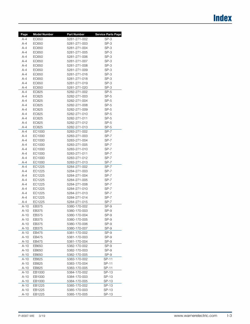
I-3www.warnerelectric.comP-8587-WE 3/19
Index
Page Model Number Part Number Service Parts Page
A-4 EC650 5281-271-002 SP-3A-4 EC650 5281-271-003 SP-3A-4 EC650 5281-271-004 SP-3A-4 EC650 5281-271-005 SP-3A-4 EC650 5281-271-006 SP-3A-4 EC650 5281-271-007 SP-3A-4 EC650 5281-271-008 SP-3A-4 EC650 5281-271-009 SP-3A-4 EC650 5281-271-016 SP-3A-4 EC650 5281-271-018 SP-3A-4 EC650 5281-271-019 SP-3A-4 EC650 5281-271-020 SP-3A-4 EC825 5282-271-002 SP-5A-4 EC825 5282-271-003 SP-5A-4 EC825 5282-271-004 SP-5A-4 EC825 5282-271-008 SP-5A-4 EC825 5282-271-009 SP-5A-4 EC825 5282-271-010 SP-5A-4 EC825 5282-271-011 SP-5A-4 EC825 5282-271-012 SP-5A-4 EC825 5282-271-013 SP-5A-4 EC1000 5283-271-002 SP-7A-4 EC1000 5283-271-003 SP-7A-4 EC1000 5283-271-004 SP-7A-4 EC1000 5283-271-005 SP-7A-4 EC1000 5283-271-010 SP-7A-4 EC1000 5283-271-011 SP-7A-4 EC1000 5283-271-012 SP-7A-4 EC1000 5283-271-013 SP-7A-4 EC1225 5284-271-002 SP-7A-4 EC1225 5284-271-003 SP-7A-4 EC1225 5284-271-004 SP-7A-4 EC1225 5284-271-005 SP-7A-4 EC1225 5284-271-008 SP-7A-4 EC1225 5284-271-010 SP-7A-4 EC1225 5284-271-013 SP-7A-4 EC1225 5284-271-014 SP-7A-4 EC1225 5284-271-015 SP-7A-10 EB375 5380-170-002 SP-9A-10 EB375 5380-170-003 SP-9A-10 EB375 5380-170-004 SP-9A-10 EB375 5380-170-005 SP-9A-10 EB375 5380-170-006 SP-9A-10 EB375 5380-170-007 SP-9A-10 EB475 5381-170-002 SP-9A-10 EB475 5381-170-003 SP-9A-10 EB475 5381-170-004 SP-9A-10 EB650 5382-170-002 SP-9A-10 EB650 5382-170-003 SP-9A-10 EB650 5382-170-005 SP-9A-10 EB825 5383-170-002 SP-11A-10 EB825 5383-170-004 SP-11A-10 EB825 5383-170-005 SP-11A-10 EB1000 5384-170-002 SP-13A-10 EB1000 5384-170-003 SP-13A-10 EB1000 5384-170-005 SP-13A-10 EB1225 5385-170-002 SP-13A-10 EB1225 5385-170-003 SP-13A-10 EB1225 5385-170-005 SP-13

Notes
I-4 www.warnerelectric.com P-8587-WE 3/19

OTHER PRODUCT SOLUTIONS FROM ALTRA MOTIONOur comprehensive product offerings include various types of clutches and brakes, overrunning clutches, engineered bearing assemblies, gearing and gear motors along with linear motion products, belted drives, couplings, limit switches, precision motors, drives & controls, miniature motors and engine braking systems.With thousands of product solutions available, Altra provides true single source convenience while meeting specific customer requirements. Many major OEMs and end users prefer Altra products as their No. 1 choice for performance and reliability.
WWW.ALTRAMOTION.COM
Premier Industrial Company Leading Brands
Engine Braking SystemsJacobs Vehicle Systems
Linear SystemsThomson Warner Linear
Specialty ComponentsKilianStromagTB Wood’s
Miniature MotorsPortescap
Precision Motors& AutomationKollmorgen
Electric Clutches & BrakesInertia DynamicsMatrixStromagWarner Electric
Heavy Duty Clutches & BrakesIndustrial ClutchStromagSvendborg BrakesTwiflexWichita Clutch
Overrunning ClutchesFormsprag ClutchMarland ClutchStieber
Engineered Couplings & Universal JointsAmeridrivesBibby TurboflexGuardian CouplingsHucoLamiflex Couplings StromagTB Wood’s
Gear Drives & Gear MotorsBauer Gear MotorBoston Gear Delroyd Worm GearNuttall Gear
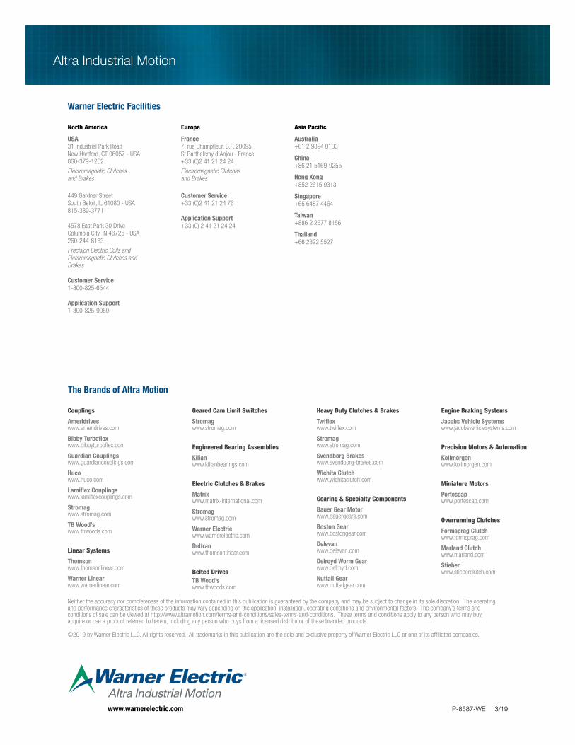
Altra Industrial Motion
P-8587-WE 3/19
The Brands of Altra Motion
Couplings
Ameridriveswww.ameridrives.com
Bibby Turbo� ex www.bibbyturbo� ex.com
Guardian Couplingswww.guardiancouplings.com
Hucowww.huco.com
Lami� ex Couplingswww.lami� excouplings.com
Stromag www.stromag.com
TB Wood’swww.tbwoods.com
Linear Systems
Thomsonwww.thomsonlinear.com
Warner Linearwww.warnerlinear.com
Geared Cam Limit Switches
Stromagwww.stromag.com
Engineered Bearing Assemblies
Kilianwww.kilianbearings.com
Electric Clutches & Brakes
Matrixwww.matrix-international.com
Stromagwww.stromag.com
Warner Electricwww.warnerelectric.com
Deltranwww.thomsonlinear.com
Belted DrivesTB Wood’s www.tbwoods.com
Heavy Duty Clutches & Brakes
Twi� exwww.twi� ex.com
Stromagwww.stromag.com
Svendborg Brakeswww.svendborg-brakes.com
Wichita Clutchwww.wichitaclutch.com
Gearing & Specialty Components
Bauer Gear Motorwww.bauergears.com
Boston Gearwww.bostongear.com
Delevanwww.delevan.com
Delroyd Worm Gearwww.delroyd.com
Nuttall Gearwww.nuttallgear.com
Engine Braking Systems
Jacobs Vehicle Systemswww.jacobsvehiclesystems.com
Precision Motors & Automation
Kollmorgenwww.kollmorgen.com
Miniature Motors
Portescapwww.portescap.com
Overrunning Clutches
Formsprag Clutchwww.formsprag.com
Marland Clutchwww.marland.com
Stieberwww.stieberclutch.com
Warner Electric Facilities
North America
USA31 Industrial Park RoadNew Hartford, CT 06057 - USA860-379-1252
Electromagnetic Clutches and Brakes
449 Gardner StreetSouth Beloit, IL 61080 - USA815-389-3771
4578 East Park 30 DriveColumbia City, IN 46725 - USA260-244-6183
Precision Electric Coils and Electromagnetic Clutches and Brakes
Customer Service1-800-825-6544
Application Support1-800-825-9050
Europe
France7, rue Champ� eur, B.P. 20095St Barthelemy d’Anjou - France+33 (0)2 41 21 24 24
Electromagnetic Clutches and Brakes
Customer Service+33 (0)2 41 21 24 76
Application Support+33 (0) 2 41 21 24 24
Asia Pacifi c
Australia +61 2 9894 0133
China+86 21 5169-9255
Hong Kong +852 2615 9313
Singapore +65 6487 4464
Taiwan +886 2 2577 8156
Thailand +66 2322 5527
Neither the accuracy nor completeness of the information contained in this publication is guaranteed by the company and may be subject to change in its sole discretion. The operating and performance characteristics of these products may vary depending on the application, installation, operating conditions and environmental factors. The company’s terms and conditions of sale can be viewed at http://www.altramotion.com/terms-and-conditions/sales-terms-and-conditions. These terms and conditions apply to any person who may buy, acquire or use a product referred to herein, including any person who buys from a licensed distributor of these branded products.
©2019 by Warner Electric LLC. All rights reserved. All trademarks in this publication are the sole and exclusive property of Warner Electric LLC or one of its af� liated companies.
www.warnerelectric.com


