SERVICE MANUALT4190
487 03 30 61.02EN

2
3
Servicemanual
Contents
Safety instructions . . . . . . . . . . . . . . . . . . . . . . . . . . . . . . . . . . . . . 5Technical data . . . . . . . . . . . . . . . . . . . . . . . . . . . . . . . . . . . . . . . . 7Description of principal components . . . . . . . . . . . . . . . . . . . . . . 11Periodic maintenance . . . . . . . . . . . . . . . . . . . . . . . . . . . . . . . . . 18Optimizing the air flow . . . . . . . . . . . . . . . . . . . . . . . . . . . . . . . . . 23Returned spare parts . . . . . . . . . . . . . . . . . . . . . . . . . . . . . . . . . . 29Error codes (see Selecta Control Service Manual)Controls . . . . . . . . . . . . . . . . . . . . . . . . . . . . . . . . . . . . . . . . . . . . 31Sensors and overheating thermostats. . . . . . . . . . . . . . . . . . . . . 37Door switch . . . . . . . . . . . . . . . . . . . . . . . . . . . . . . . . . . . . . . . . . 45Motor and transmission . . . . . . . . . . . . . . . . . . . . . . . . . . . . . . . . 49Heating . . . . . . . . . . . . . . . . . . . . . . . . . . . . . . . . . . . . . . . . . . . . 55Drum with bearing . . . . . . . . . . . . . . . . . . . . . . . . . . . . . . . . . . . . 67Cabinet, door reversal . . . . . . . . . . . . . . . . . . . . . . . . . . . . . . . . . 73 RMC. . . . . . . . . . . . . . . . . . . . . . . . . . . . . . . . . . . . . . . . . . . . . . . 75

4
5
Safety instructionsServicemanual
Servicing the dryer Refer servicing to qualified personnel. Improper servicing can result in hazardous conditions, fire, explosion, property damage, and personal injury.
Some components may have sharp edges! Wear gloves when handling mechanical components.
*Applies only to floor mops containing polypropylene.
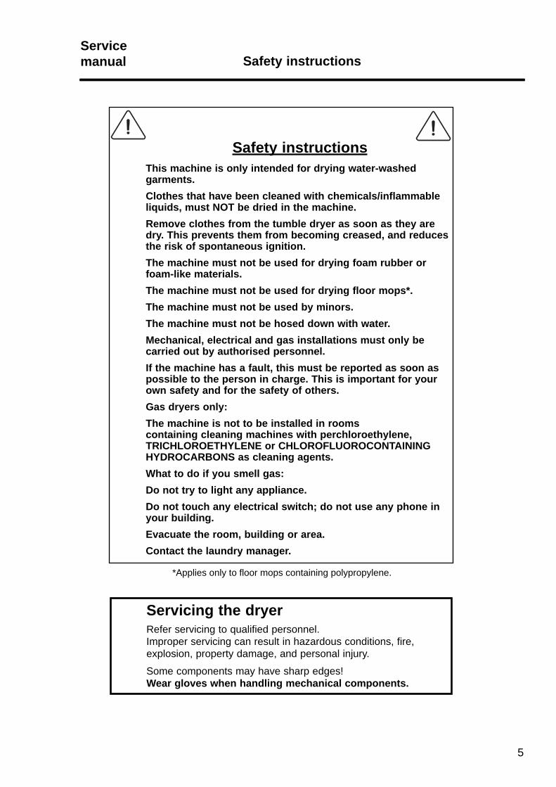
Safety instructionsThis machine is only intended for drying water-washed garments.Clothes that have been cleaned with chemicals/inflammable liquids, must NOT be dried in the machine.Remove clothes from the tumble dryer as soon as they are dry. This prevents them from becoming creased, and reduces the risk of spontaneous ignition.The machine must not be used for drying foam rubber or foam-like materials.The machine must not be used for drying floor mops*.The machine must not be used by minors.The machine must not be hosed down with water.Mechanical, electrical and gas installations must only be carried out by authorised personnel.If the machine has a fault, this must be reported as soon as possible to the person in charge. This is important for your own safety and for the safety of others.Gas dryers only:The machine is not to be installed in rooms containing cleaning machines with perchloroethylene, TRICHLOROETHYLENE or CHLOROFLUOROCONTAINING HYDROCARBONS as cleaning agents.What to do if you smell gas:Do not try to light any appliance.Do not touch any electrical switch; do not use any phone in your building.Evacuate the room, building or area.Contact the laundry manager.

6

7
2. Technical dataServicemanual
Contents
Technical data, type T4190 . . . . . . . . . . . . . . . . . . . . . . . . . . . . . . . . . . . 8
Technical data, motor specifications . . . . . . . . . . . . . . . . . . . . . . . . . . . . 9
Technical dataServicemanual

Technical dataServicemanual
8
Technical data - type T4190
Heating Electric GasDrum volume: 190 litres 190 litres
Weight net: 103 kg 103 kg
Drum: Diameter 680 mm 680 mm Depth 555 mm 555 mm Revolutions per minute 50 rpm 50 rpm
Capacity: Factor 1:25 7.5 kg 7.5 kg Factor 1:33 5.8 kg 5.8 kg
Heat effect: Electric heating: 6.0 kW 6.6 kW 8.0 kW 8.0 kW
Air consumption: Heat effect 6.0 kW / 6.6 kW 270 m3/h 270 m3/h Heat effect 8.0 kW / 8.0 kW 290 m3/h 290 m3/h
Piping: Evacuation Ø 125 Ø 125
Gas piping: ISO 7/1 R 1/2
Pressure drop: Evacuation 6.0 kW / 6.6 kW 380 Pa 380 Pa 8.0 kW / 8.0 kW 350 Pa 350 Pa
Sound power level: Lw <68 dB (A) <68 dB (A)
9
Technical dataServicemanual
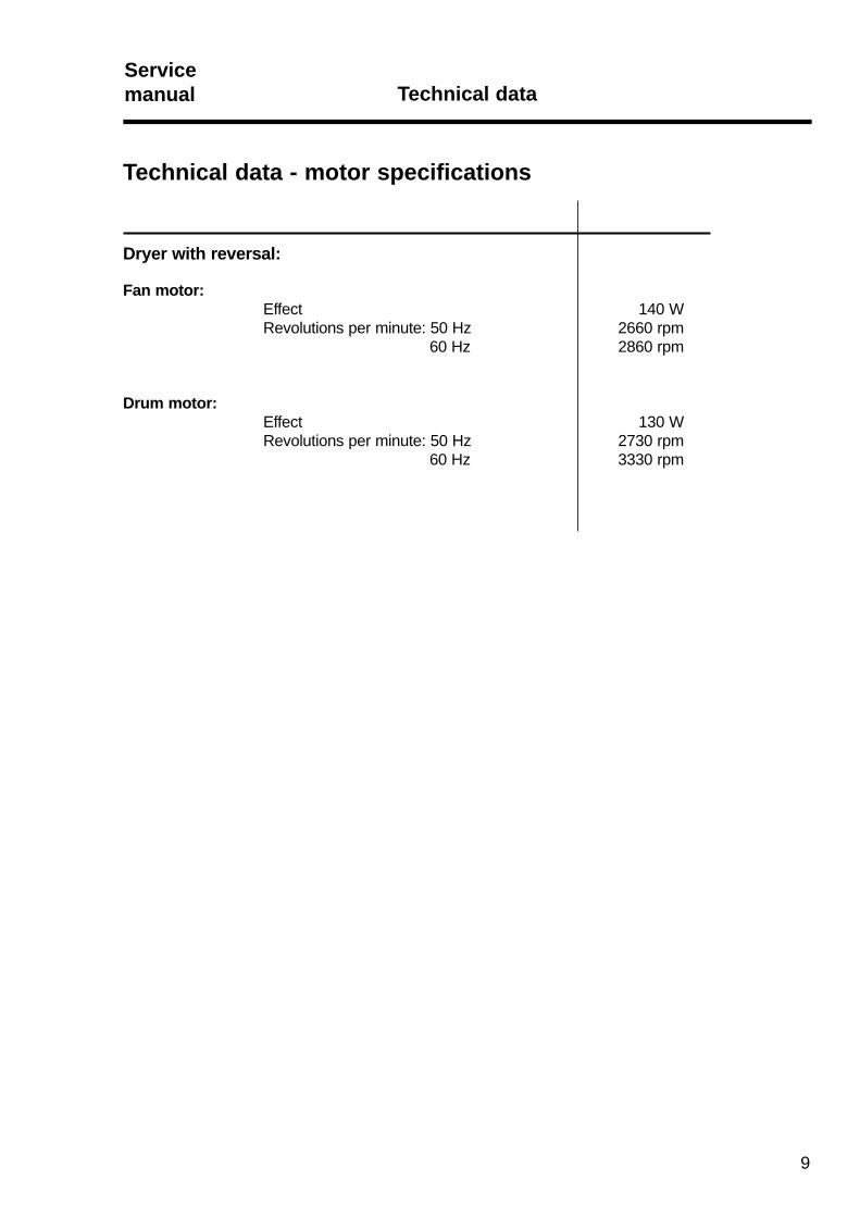
Technical data - motor specifications
Dryer with reversal:
Fan motor: Effect 140 W Revolutions per minute: 50 Hz 2660 rpm 60 Hz 2860 rpm
Drum motor: Effect 130 W Revolutions per minute: 50 Hz 2730 rpm 60 Hz 3330 rpm

10

11
Description of principal componentsServicemanual
Contents
Description . . . . . . . . . . . . . . . . . . . . . . . . . . . . . . . . . . . . . . . . . . . . . . 12
Position of components (Electric) . . . . . . . . . . . . . . . . . . . . . . . . . . . . . 14
Position of components (Gas). . . . . . . . . . . . . . . . . . . . . . . . . . . . . . . . 16
Description of principal componentsServicemanual
12
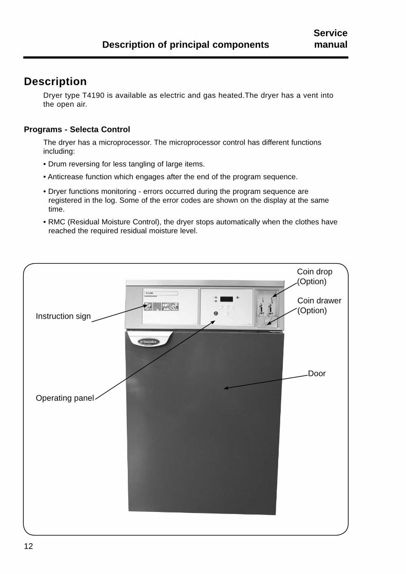
DescriptionDryer type T4190 is available as electric and gas heated.The dryer has a vent into the open air.
Programs - Selecta Control The dryer has a microprocessor. The microprocessor control has different functions including:
• Drum reversing for less tangling of large items.
• Anticrease function which engages after the end of the program sequence.
• Dryer functions monitoring - errors occurred during the program sequence are registered in the log. Some of the error codes are shown on the display at the same time.
• RMC (Residual Moisture Control), the dryer stops automatically when the clothes have reached the required residual moisture level.
Coin drop(Option)
Coin drawer(Option)
Door
Instruction sign
Operating panel
13
Description of principal componentsServicemanual
Loading doorNormally the dryer has a right-hinged door.
The door is, however, reversible (see section "cabinet, door reversal").
A door switch ensures that the dryer stops automatically if the dryer is opened during the program sequence, see section "door switch".
Operating panelDepending on configuration. Can be equipped with one or serveral of the following:
• Buttons for setting programs, temperatures, and drying time.
• Start/stop button.
• Display showing program selection, remaining drying time and error code, if any.
• Heating indicator, lamp lights when heating is on.
Coin drop / card readerThe dryer is available with a factory-installed coin drop, a factory-installed card-start system, or it can be prepared for field installation of a card start system.
On vending models, insertion of a coin or card buys an owner-programmed drying time.
MotorThe dryer has two motors, motor 1 operates the blower and motor 2 operates the drum.
4 10
12
93
8
7
62
5
1
11
10
10
4
1012
93 8
72
5
1
6
Description of principal componentsServicemanual
14
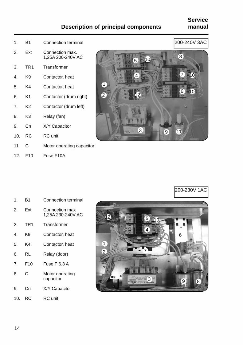
1. B1 Connection terminal
2. Ext Connection max. 1,25A 200-240V AC
3. TR1 Transformer
4. K9 Contactor, heat
5. K4 Contactor, heat
6. K1 Contactor (drum right)
7. K2 Contactor (drum left)
8. K3 Relay (fan)
9. Cn X/Y Capacitor
10. RC RC unit
11. C Motor operating capacitor
12. F10 Fuse F10A
200-240V 3AC
200-230V 1AC
1. B1 Connection terminal
2. Ext Connection max 1,25A 230-240V AC
3. TR1 Transformer
4. K9 Contactor, heat
5. K4 Contactor, heat
6. RL Relay (door)
7. F10 Fuse F 6.3 A
8. C Motor operating capacitor
9. Cn X/Y Capacitor
10. RC RC unit
4 10
10
1193
8
7
62
5
1
4
10
10
10
108
7
6
3 9
2
5
1
10
15
Description of principal componentsServicemanual
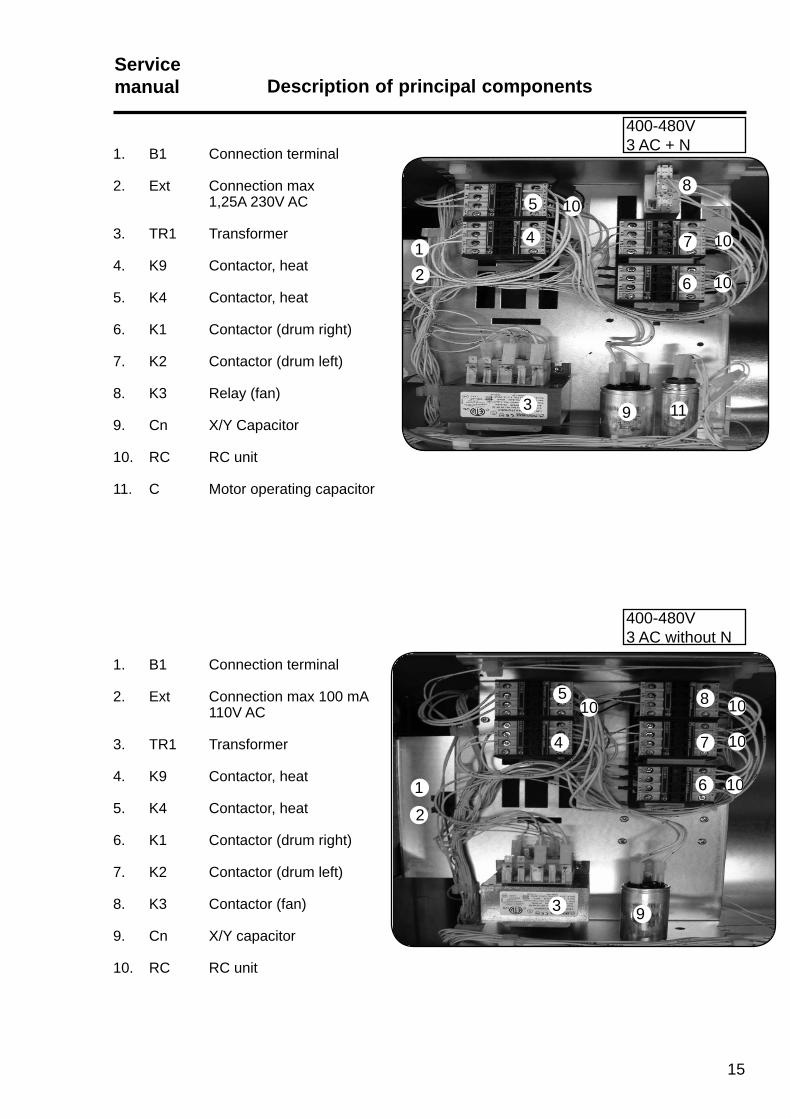
1. B1 Connection terminal
2. Ext Connection max 100 mA 110V AC
3. TR1 Transformer
4. K9 Contactor, heat
5. K4 Contactor, heat
6. K1 Contactor (drum right)
7. K2 Contactor (drum left)
8. K3 Contactor (fan)
9. Cn X/Y capacitor
10. RC RC unit
400-480V3 AC without N
1. B1 Connection terminal
2. Ext Connection max 1,25A 230V AC
3. TR1 Transformer
4. K9 Contactor, heat
5. K4 Contactor, heat
6. K1 Contactor (drum right)
7. K2 Contactor (drum left)
8. K3 Relay (fan)
9. Cn X/Y Capacitor
10. RC RC unit
11. C Motor operating capacitor
400-480V3 AC + N
8 3
1
6
7
7
4
6
89 3
7
7
41
5
2
2
6
Description of principal componentsServicemanual
16
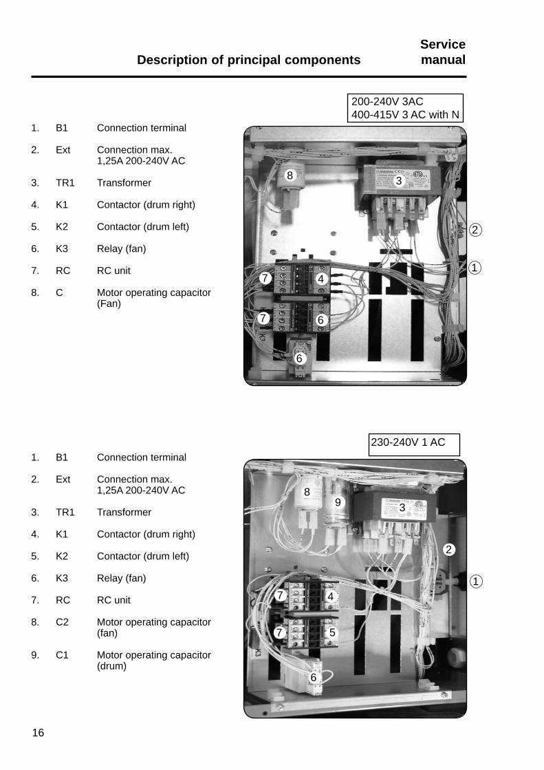
1. B1 Connection terminal
2. Ext Connection max. 1,25A 200-240V AC
3. TR1 Transformer
4. K1 Contactor (drum right)
5. K2 Contactor (drum left)
6. K3 Relay (fan)
7. RC RC unit
8. C Motor operating capacitor (Fan)
1. B1 Connection terminal
2. Ext Connection max. 1,25A 200-240V AC
3. TR1 Transformer
4. K1 Contactor (drum right)
5. K2 Contactor (drum left)
6. K3 Relay (fan)
7. RC RC unit
8. C2 Motor operating capacitor (fan)
9. C1 Motor operating capacitor (drum)
200-240V 3AC400-415V 3 AC with N
230-240V 1 AC

1
2
3
7
7
7
4
5
6
17
Description of principal componentsServicemanual
1. B1 Connection terminal
2. Ext Connection max. 100 mA 110V
3. TR1 Transformer
4. K1 Contactor (drum right)
5. K2 Contactor (drum left)
6. K3 Contactor (fan)
7. RC RC unit
400-480V 3 AC-without N

18

19
Periodic maintenanceServicemanual
Content
Periodic maintenance . . . . . . . . . . . . . . . . . . . . . . . . . . . . . . . . . . . . . . . 20

Periodic maintenanceServicemanual
20
Functional inspection
Functional inspection comprises:1. Checking the door switch.2. Test run.
1. Check the door switchCheck whether the safety lock works. The drum must stop when the door is opened. When the door is closed again, the tumbler must not start until the start button is pressed, fig. 1.
2. Test runLet the tumble dryer work on a program with heat for 5 minutes; then check by opening the door and feeling with your hand whether the heating works.
MaintenanceThe following should be carried out at regular intervals, depending on the frequency of use.
Daily• Check that the drum stops when the door is
opened.
• Check that the lint screen under the door has been cleaned. Use a soft brush or your hand, fig. 2.
• Check that the lint screen is not damaged.
• Check that the tumble dryer will not start until the start/stop button has been activated.
1
2

21
Periodic maintenanceServicemanual
Monthly • Wipe off/clean drum and lifters with citric acid
(Acidum citricum). If soap/softener residue remains, it is recommended also to use a coarse sponge.
Lack of cleaning the lifters can reduce the automatic residual moisture control in the clothes resluting in the clothes being moister than requested when the program has ended, fig. 1.
Quarterly/Semi-annually• Check that the fresh-air intake at the rear of the
tumble is not clogged by lint or blocked in any other way.
• Check that the filter is not broken.
• Clean drum and lifters with a mild detergent (using a sponge) at least once every quarter.
• If the filter is defective it needs replacing.
• At least once a year a skilled expert should check the inside wearing parts of the tumble dryer and clean them of lint.
1
MaintenanceThe area surrounding the dryerFresh-air intake to the room
Check that the fresh-air intake to the room and the exhaust ducts/pipes from the room are not clogged by lint/dust or blocked in any other way.
Dryer areaCheck that the dryer area is clear and free from combustible materials, gasoline and other flammable vapours and liquids.

22

23
Optimizing the air flowServicemanual Optimizing the air flowServicemanual
Contents
Outlet dimensioning ...............................................................................24
Blower characteristic ..............................................................................25

Optimizing the air flowServicemanual
24
Type Effect
kW
Optimumair volume
m3/h
Correspondingback pressure
Pa
Air volumeThe curves on the next page shows the characteristics of the dryer. By measuring or calculating the back pressure of the outlet pipe it is hereby possible to find the corresponding air flow into the room and through the dryer and exhaust.
Outlet dimensioningIt is important that the dryer has the correct air volume compared to each dryer’s effect. If the air flow is below the minimum, the dryer will be forced to switch the heating off thus prolonging the time it will take to dry the load.An air flow above the needed is unnecessary and can result in a cold laundry room and noise from the piping and outlet and in extreme cases prolonged drying time.
Table with air volume and dryer effectOptimum volume
T4190 6.0 270 270
8.0 290 220
Air flow

x = m3/h
Y = Pa
100 200 300 40000
100
200
300
400
500
x = m3/h
Y = Pa
100 200 300 40000
100
200
300
400
500
25
Optimizing the air flowServicemanual
X = Air consumptionY = Back pressure
The grey area marks the recommended working area.
Adjusting the dryer:Diagram with pressure drop curve type T4190.
T4190 6 kW
T4190 8 kW

A B
Optimizing the air flowServicemanual
26
Gas type Connection Nozzle Nozzle Air
Pressure Pressure Restrictors
Denmark LPG 30 30 3 ANorway GNH 20 8.2 2.35Sweden Finland Italy LPG 28/37 28/37 1.3 A England GNH 20 8.2 2.35 Spain Portugal Ireland Greece
France LPG 28/37 28/37 1.3 A Belgium GNH 20/25 20/25 1.95 GNL 20/25 20/25 1.95
Germany LPG 50 30 1.3 A GNH 20 8.2 2.35 GNL 20 12.1 2.35
Holland LPG 30 30 1.3 A GNL 25 12.1 2.35
Austria LPG 50 30 1.3 A GNH 20 8.2 2.35 Japan LPG 28 28 1.3 A Denmark Town gas 8 4.5 3.95 BSweden Group a Italy Town gas 8 3.5 3.95 B Group b
26
Gas installationTables of pressure and adjustments.
Note Because of the differences in gas installation regulations in European Union it is important to use the Italian-language manual in Italy and the French-language manual in France ect.
T4190 heat effect: 6 kW

A C
27
Optimizing the air flowServicemanual
Gas installationTables of pressure and adjustments.
T4190 heat effect: 8 kW
Note Because of the differences in gas installation regulations in European Union it is important to use the Italian-language manual in Italy and the French-language manual in France ect.
Gas type Connection Nozzle Nozzle Air
Pressure Pressure Restrictors
Denmark LPG 30 30 1.45 ANorway GNH 20 9 2.65Sweden Finland Italy LPG 28/37 28/37 1.45 A England GNH 20 9 2.65 Spain Portugal Ireland Greece
France LPG 28/37 28/37 1.45 A Belgium GNH 20/25 20/25 2.2 GNL 20/25 20/25 2.2
Germany LPG 50 30 1.45 A GNH 20 9 2.65 GNL 20 13.4 2.65
Holland LPG 30 28.8 1.25 A GNL 25 13.4 2.65
Austria LPG 50 30 1.25 A GNH 20 9 2.65 Japan LPG 28 28 1.45 A Denmark Town gas 8 4.5 4.45 CSweden Group a Italy Town gas 8 3.5 4.45 C Group b

28

29
Returned defective partsServicemanual
Contents
Returning defective parts within the guarantee period . . . . . . . . . . . . 30
Packing and dispatch . . . . . . . . . . . . . . . . . . . . . . . . . . . . . . . . . . . . . 30
Returned defective partsServicemanual
30
Returning defective parts within the guarantee periodThe quality department at Electrolux Laundry Systems Denmark A/S is in possession of a list of critical parts which must be returned immediately after the replacement.
This list can be ordered by contacting the service department.
In order to return replaced parts, which are not on the list, a prior agreement must be made with the quality department.
With the returned parts / machines a completed guarantee claim must be enclosed.
Packing and dispatchReturned parts must be packed in such a way that they can resist the transportation without further damage. During transport mechanical parts must be unmovable. Electrical components and boards must be wrapped in ESD approved bags.
All dispatches to Electrolux Laundry Systems Denmark A/S must be marked in such a way that it is obvious to whom / which department they are sent.
Contents
Printed circuit board . . . . . . . . . . . . . . . . . . . . . . . . . . . . . . . . . . . . . . . 32
Connecting accessory systems . . . . . . . . . . . . . . . . . . . . . . . . . . . . . . 32
Connection to network/Central Panel . . . . . . . . . . . . . . . . . . . . . . . . . . 33
Programming. . . . . . . . . . . . . . . . . . . . . . . . . . . . . . . . . . . . . . . . . . . . . 34
Replacement of PCB. . . . . . . . . . . . . . . . . . . . . . . . . . . . . . . . . . . . . . . 35
Circuit boards MUST be protected from static electricity!
Remember!
• Always use an earthed wrist strap.
• Without the antistatic wrapping, the board is unprotected.
• Keep all items that can cause static discharge (such as plastic bags, fabric, and the like) away from the circuit board.
• Items like plastic, foam plastic, nylon, or cellophane wrapping are all big generators of static electricity.
• Static electricity can not be felt, heard or seen till the voltage reaches 2500V.
• Board components can be damaged by static electricity under 100V.
31
ControlsServicemanual

ControlsServicemanual
32
Control PCB
Printed circuit boardThe PCB is placed behind the operating panels, fig. 1.
The PCB contains a board with display, indicator lamps.
The PCB contains a button A for Switching to Programming mode,See description in Service Manual for Selecta II Control.
The PCB contains a button B for gas reset (Only activated on gas dryer).
Connecting accessory systemsDifferent payment systems can be connected to the PCB, see description in Service Manual for Selecta II Control.
1
33
ControlsServicemanual
1
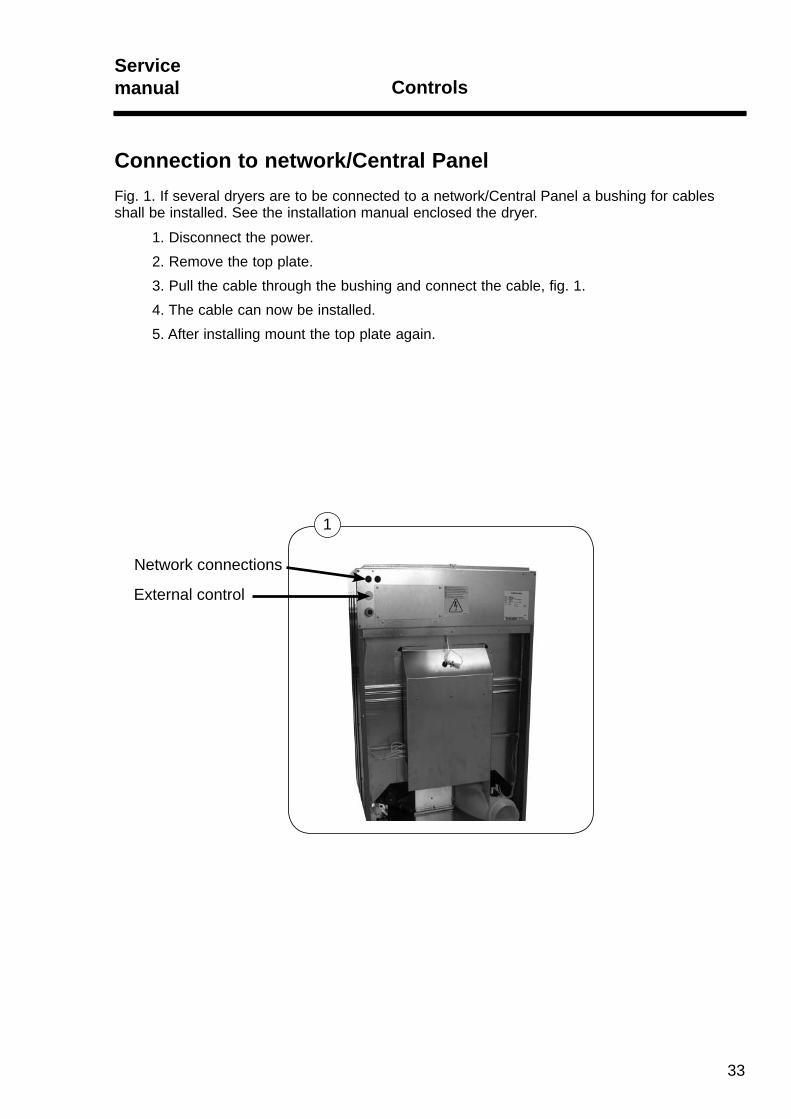
Connection to network/Central PanelFig. 1. If several dryers are to be connected to a network/Central Panel a bushing for cables shall be installed. See the installation manual enclosed the dryer.
1. Disconnect the power.2. Remove the top plate.3. Pull the cable through the bushing and connect the cable, fig. 1.4. The cable can now be installed.5. After installing mount the top plate again.
Network connections
External control

ControlsServicemanual
34
A B
ProgrammingTo enter the programming mode press service button A.After pressing the service button A the display shows: 0 -- = Group 0.Program the dryer, see "Service Manual for Selecta Control from ver. 4.xx" for programming details.
High voltage on the printed circuit boardDo not touch the printed circuit board.The shaded areas indicate high voltage.
35
ControlsServicemanual
Replacement of PCBThe PCB is not serviceable. It must be replaced if it fails, see Selecta Control Service Manual.
The PCB can be ordered as a spare part.
The spare part consists of: Printed circuit board with fuses in anti-static packing and instructions.
The PCB Selecta Control software is pre-programmed with specific features and may need to be “post-programmed” after installation.
Installation 1. Disconnect the power supply to the dryer.
2. Remove the top plate to access the defected print board. (See earlier in this section).
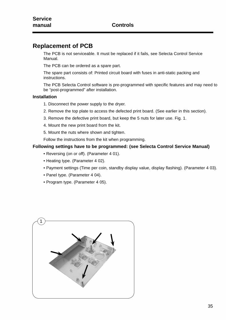
3. Remove the defective print board, but keep the 5 nuts for later use. Fig. 1.
4. Mount the new print board from the kit.
5. Mount the nuts where shown and tighten.
Follow the instructions from the kit when programming.
Following settings have to be programmed: (see Selecta Control Service Manual)• Reversing (on or off). (Parameter 4 01).
• Heating type. (Parameter 4 02).
• Payment settings (Time per coin, standby display value, display flashing). (Parameter 4 03).
• Panel type. (Parameter 4 04).
• Program type. (Parameter 4 05).
1

36
Service Manual for Selecta Control software version from 4.xxCertain parameters need to be set after installation, according to the characteristics of the dryer and the preferences of the owner.
See Service Manual for Selecta Control software version from version 4.xx for further details.
ControlsServicemanual

Contents
Overview, inlet air:. . . . . . . . . . . . . . . . . . . . . . . . . . . . . . . . . . . . . . . . . 38
Overheating thermostat . . . . . . . . . . . . . . . . . . . . . . . . . . . . . . . . 39
Thermistor element (PT100 sensor). . . . . . . . . . . . . . . . . . . . . . . 40
Overview, outlet air: . . . . . . . . . . . . . . . . . . . . . . . . . . . . . . . . . . . . . . . 41
Overheating thermostat . . . . . . . . . . . . . . . . . . . . . . . . . . . . . . . . 42
Thermistor element (NTC sensor) . . . . . . . . . . . . . . . . . . . . . . . . 43
Sensors and overheating thermostatsServicemanual
37

Sensors and overheating thermostatsServicemanual
38
Overview, Inlet airPosition of sensors and overheating thermostats for inlet air.
Fig. 1. Overheating thermostat and thermistor element, electric heated dryer.
On the following pages manual resetting is described.
1
AA
39
Sensors and overheating thermostatsServicemanual
A
1
Inlet air - Overheating thermostatFunction
The inlet overheating thermostat opens in the event of overheating, and shuts off the dryer.
The thermostat has to be reset manually.
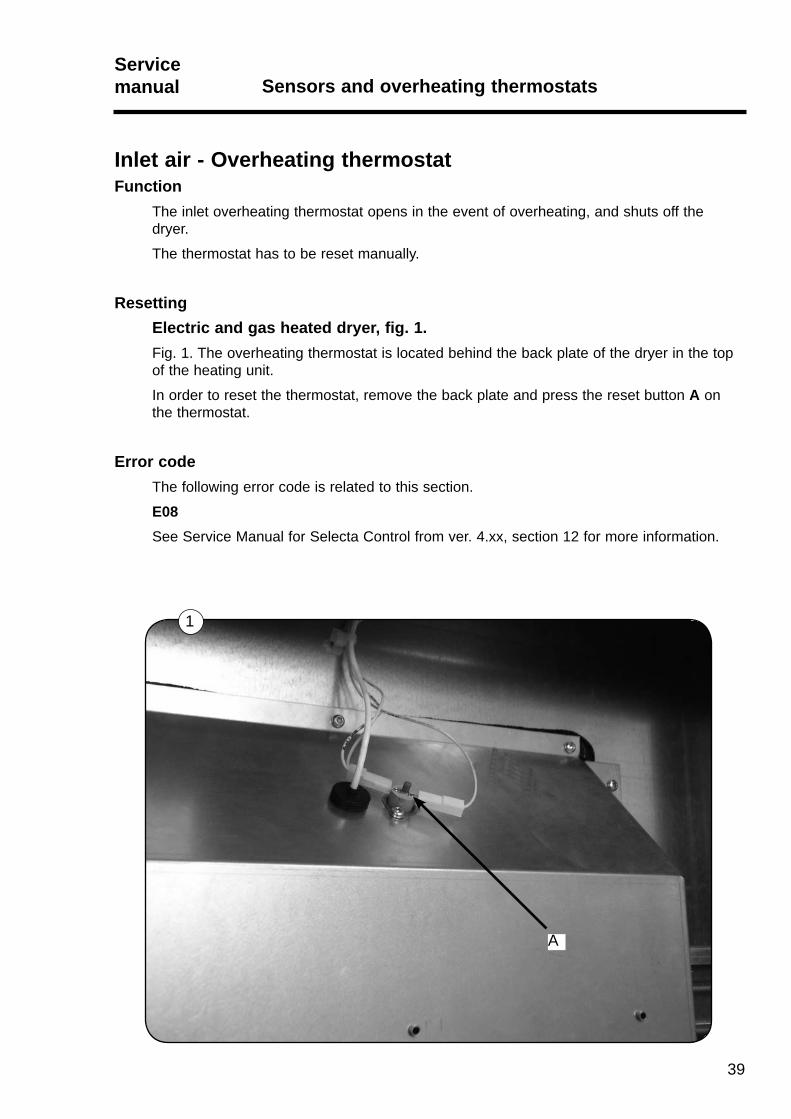
ResettingElectric and gas heated dryer, fig. 1.Fig. 1. The overheating thermostat is located behind the back plate of the dryer in the top of the heating unit.
In order to reset the thermostat, remove the back plate and press the reset button A on the thermostat.
Error codeThe following error code is related to this section.
E08See Service Manual for Selecta Control from ver. 4.xx, section 12 for more information.
Sensors and overheating thermostatsServicemanual
40
1
A
Inlet air - Thermistor element (PT100 sensor)Function
The thermistor element measures the temperature of the heated air entering the drum.
The resistance of this device is normally 110 Ohms at 20°C (68°F) and increases as the temperature rises.
The signal is returned to the PCB and this ensures that the inlet air does not become excessively hot, thus preventing scorching of garments.
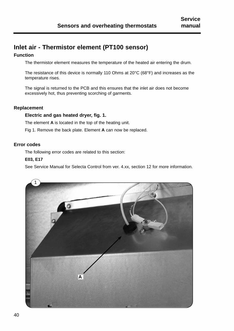
ReplacementElectric and gas heated dryer, fig. 1.The element A is located in the top of the heating unit.
Fig 1. Remove the back plate. Element A can now be replaced.
Error codesThe following error codes are related to this section:
E03, E17See Service Manual for Selecta Control from ver. 4.xx, section 12 for more information.
41
Sensors and overheating thermostatsServicemanual
Overview, Outlet airPositioning sensors and overheating thermostats for outlet air.
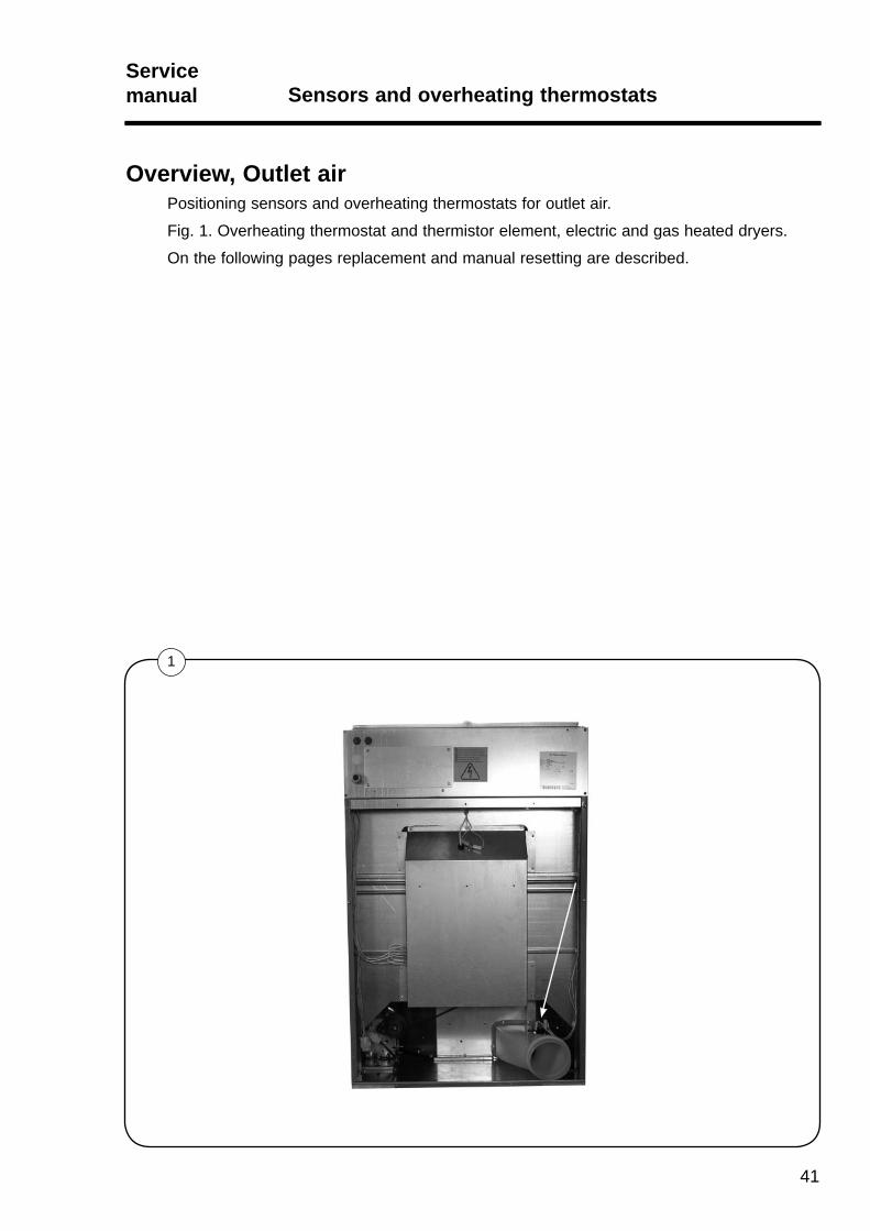
Fig. 1. Overheating thermostat and thermistor element, electric and gas heated dryers.
On the following pages replacement and manual resetting are described.
1
Sensors and overheating thermostatsServicemanual
42
A
1
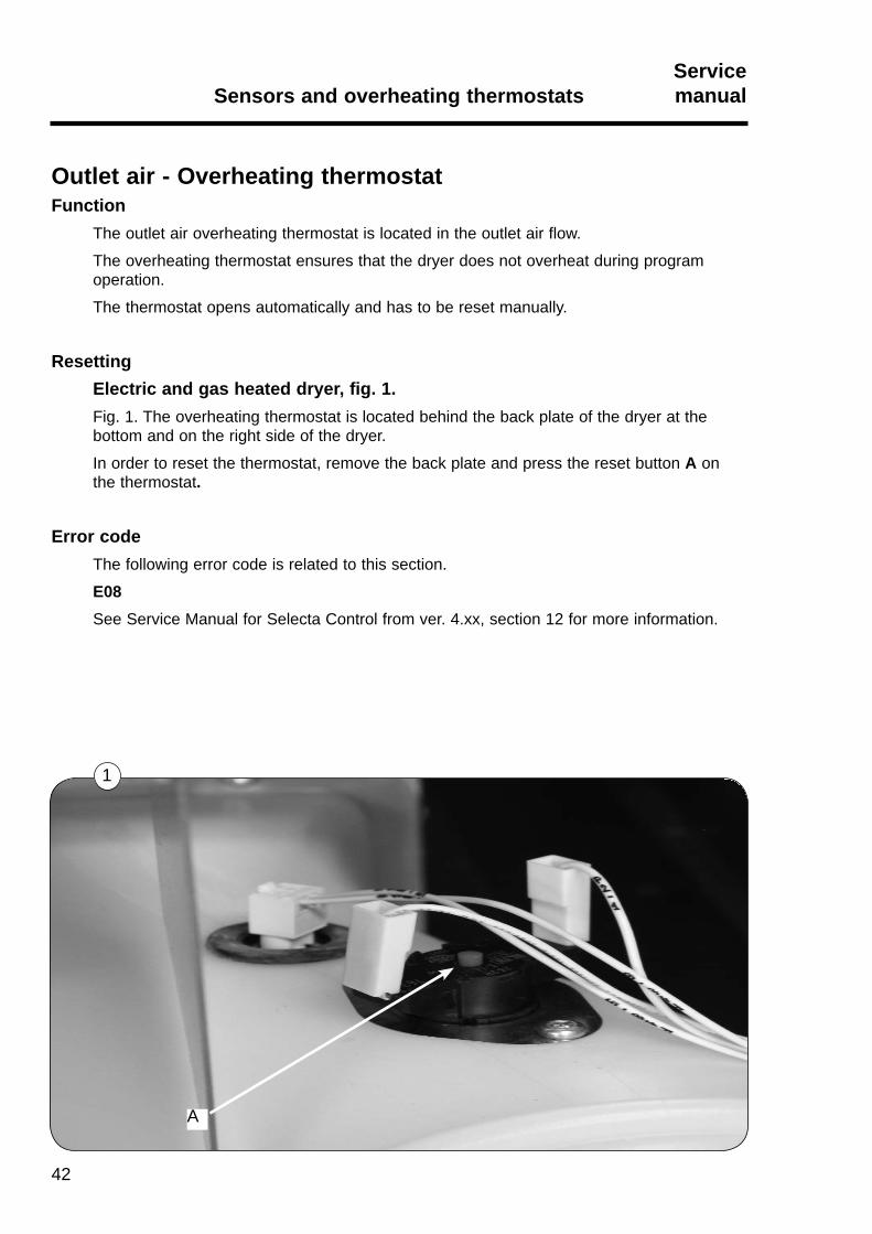
Outlet air - Overheating thermostatFunction
The outlet air overheating thermostat is located in the outlet air flow.
The overheating thermostat ensures that the dryer does not overheat during program operation.
The thermostat opens automatically and has to be reset manually.
ResettingElectric and gas heated dryer, fig. 1.Fig. 1. The overheating thermostat is located behind the back plate of the dryer at the bottom and on the right side of the dryer.
In order to reset the thermostat, remove the back plate and press the reset button A on the thermostat.
Error codeThe following error code is related to this section.
E08See Service Manual for Selecta Control from ver. 4.xx, section 12 for more information.
43
Sensors and overheating thermostatsServicemanual
A
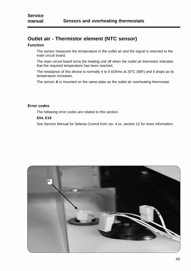
Outlet air - Thermistor element (NTC sensor)Function
The sensor measures the temperature in the outlet air and the signal is returned to the main circuit board.
The main circuit board turns the heating unit off when the outlet air thermistor indicates that the required temperature has been reached.
The resistance of this device is normally 4 to 6 kOhms at 20°C (68F) and it drops as its temperature increases.
The sensor A is mounted on the same plate as the outlet air overheating thermostat.
Error codesThe following error codes are related to this section.
E04, E18 See Service Manual for Selecta Control from ver. 4.xx, section 12 for more information.

44
45
Door switch and lint filter switchServicemanual Door switch
Contents
Door switch . . . . . . . . . . . . . . . . . . . . . . . . . . . . . . . . . . . . . . . . . . . . . . 46
Testing door lock on loading door . . . . . . . . . . . . . . . . . . . . . . . . . . . . . 48
Door switch and lint filter switchServicemanual
46
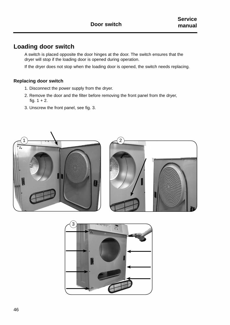
Loading door switchA switch is placed opposite the door hinges at the door. The switch ensures that the dryer will stop if the loading door is opened during operation.
If the dryer does not stop when the loading door is opened, the switch needs replacing.
Replacing door switch1. Disconnect the power supply from the dryer.
2. Remove the door and the filter before removing the front panel from the dryer, fig. 1 + 2.
3. Unscrew the front panel, see fig. 3.
1 2
3
Door switch

40 mm
47
Door switch and lint filter switchServicemanual
4. Unplug the plug and cut the cable ties, fig. 1.
5. Dismount the door switch, fig. 2.
5. Mount the new switch.
6. Connect the plug.
7. Re-assemble and test the new door switch, as follows:
Testing door switch1. Connect the power supply.2. Start the dryer.3. Fig. 1. Check that the fan, drum rotation and heat all stop when the door is opened max. 40 mm.
Door switch
3
21
1
Door switch and lint filter switchServicemanual
48
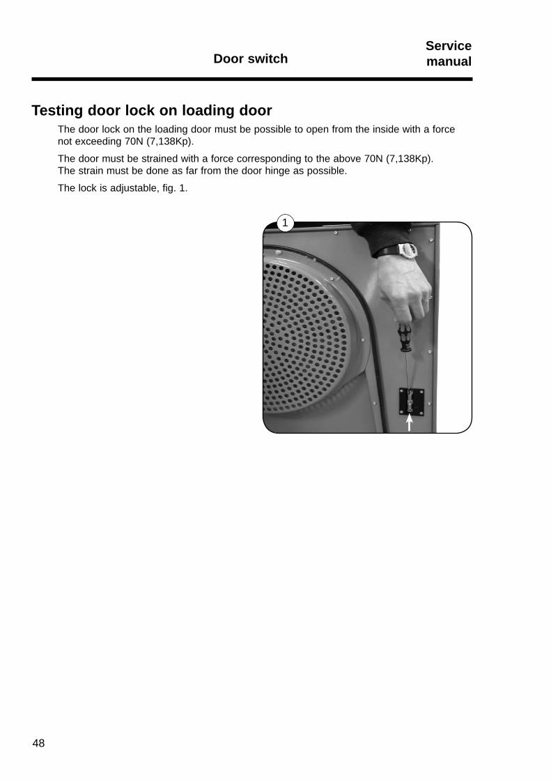
Testing door lock on loading doorThe door lock on the loading door must be possible to open from the inside with a force not exceeding 70N (7,138Kp).
The door must be strained with a force corresponding to the above 70N (7,138Kp). The strain must be done as far from the door hinge as possible.
The lock is adjustable, fig. 1.
Door switch
Content
Motor description . . . . . . . . . . . . . . . . . . . . . . . . . . . . . . . . . . . . . . . . . . . 50
Replacement of motor . . . . . . . . . . . . . . . . . . . . . . . . . . . . . . . . . . . . . . . 50
Replacing parts on transmission . . . . . . . . . . . . . . . . . . . . . . . . . . . . . . . 51
Replacement on fan module. . . . . . . . . . . . . . . . . . . . . . . . . . . . . . . . . . . 52
Motor and transmissionServicemanual
49
Motor and transmissionServicemanual
50
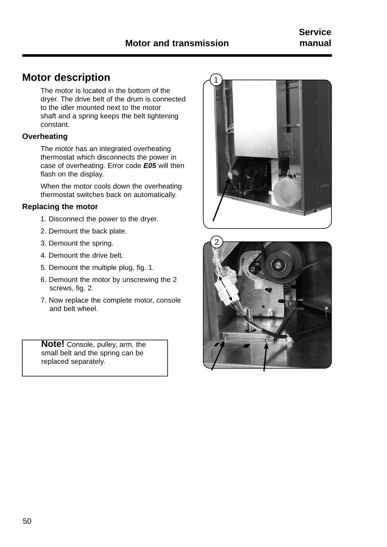
Motor descriptionThe motor is located in the bottom of the dryer. The drive belt of the drum is connected to the idler mounted next to the motor shaft and a spring keeps the belt tightening constant.
OverheatingThe motor has an integrated overheating thermostat which disconnects the power in case of overheating. Error code E05 will then flash on the display.
When the motor cools down the overheating thermostat switches back on automatically.
Replacing the motor1. Disconnect the power to the dryer.
2. Demount the back plate.
3. Demount the spring.
4. Demount the drive belt.
5. Demount the multiple plug, fig. 1.
6. Demount the motor by unscrewing the 2 screws, fig. 2.
7. Now replace the complete motor, console and belt wheel.
1
2
Note! Console, pulley, arm, the small belt and the spring can be replaced separately.

A
51
Motor and transmissionServicemanual
Replacing parts on transmission
1. Disconnect the power supply from the dryer.
2. Dismount drum belt and motor.
3. Fig. 1. Dismount spring B.
4. Fig. 1. Dismount transmission belt C.
5. Fig. 1. Dismount snap ring D, washer and arm with idler.
6. Fig. 1. Dismount snap ring, washer, bearings and idler on dismounted arm.
7. Fig. 1. Dismount plastic bearing ring E.
8. Fig. 2. Check that there is no burr on the motor bearing shield F - if necessary remove burr with a file.
9. Mount plastic bearing ring E.
10. Mount idler, bearings, washer and snap ring on arm.
11. Fig. 3. Mount arm G with idler and washer on the motor.
12. Mount snap ring D.
13. Mount transmission belt C.
14. Fig. 4. Mount new spring. It is important that the spring is mounted in the outer hole.
15. Mount the complete motor.
16. Mount drum belt.
17. Assemble the dryer and test it.
18. Check that the belts go correctly around the wheel.
Note!In order to mount the idler A turn the arm back and forth, lubricate the shaft end with copper grease if necessary.
Do not hit or use excessive force on the arm!
1B
C
DE
2
F
G
4
3

Motor and transmissionServicemanual
52
D E
A1
BC
2
43
Replacement fan module:
1. Dismount the power to the dryer.
2. Disconnect motor plug A and the overheating thermostats B, disconnect the NTC sensor C, fi g. 1.
3. Unscrew these two screws on the right side and three screws on the left side of the fan house, fi g. 2. 4. Remove the fan house, fi g. 3.
5. Unscrew the fan house D and turn fan motor on bottom plate E upside-down, fi g. 4.
53
Motor and transmissionServicemanual
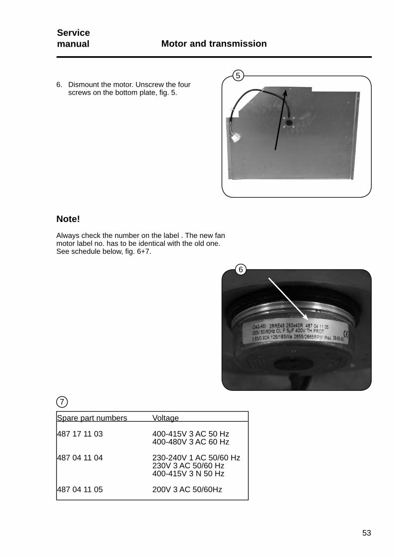
Note!Always check the number on the label . The new fan motor label no. has to be identical with the old one.See schedule below, fi g. 6+7.
6. Dismount the motor. Unscrew the four screws on the bottom plate, fi g. 5.
Spare part numbers Voltage
487 17 11 03 400-415V 3 AC 50 Hz 400-480V 3 AC 60 Hz
487 04 11 04 230-240V 1 AC 50/60 Hz 230V 3 AC 50/60 Hz 400-415V 3 N 50 Hz
487 04 11 05 200V 3 AC 50/60Hz
7
6
5

54

55
HeatingServicemanual
Content
Electric heated dryers . . . . . . . . . . . . . . . . . . . . . . . . . . . . . . . . . . . . . . . . 56
Replacing electric heating element . . . . . . . . . . . . . . . . . . . . . . . . . . . . . . 57
Gas heated dryers . . . . . . . . . . . . . . . . . . . . . . . . . . . . . . . . . . . . . . . . . . 59
Replacing gas heating element. . . . . . . . . . . . . . . . . . . . . . . . . . . . . . . . . 60
Gas error E14 . . . . . . . . . . . . . . . . . . . . . . . . . . . . . . . . . . . . . . . . . . . . . . 64
Gas error reset . . . . . . . . . . . . . . . . . . . . . . . . . . . . . . . . . . . . . . . . . . . . . 65
56
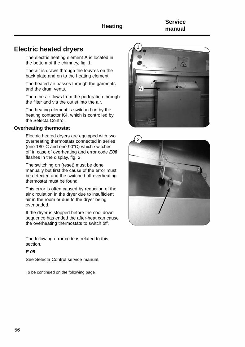
Electric heated dryersThe electric heating element A is located in the bottom of the chimney, fig. 1.
The air is drawn through the louvres on the back plate and on to the heating element.
The heated air passes through the garments and the drum vents.
Then the air flows from the perforation through the filter and via the outlet into the air.
The heating element is switched on by the heating contactor K4, which is controlled bythe Selecta Control.
Overheating thermostat Electric heated dryers are equipped with two overheating thermostats connected in series (one 180°C and one 90°C) which switches off in case of overheating and error code E08 flashes in the display, fig. 2.
The switching on (reset) must be done manually but first the cause of the error must be detected and the switched off overheating thermostat must be found.
This error is often caused by reduction of the air circulation in the dryer due to insufficient air in the room or due to the dryer being overloaded.
If the dryer is stopped before the cool down sequence has ended the after-heat can cause the overheating thermostats to switch off.
The following error code is related to this section.
E 08 See Selecta Control service manual.
To be continued on the following page
1
2
A
HeatingServicemanual

57
Continued from the previous page
There are different types of heating elements depending on voltage and effect, fig. 1:
To order the correct heating element, see label on the heating element for voltage and effect.
Replacing heating element 1. Disconnect the power to the dryer. 2. Demount the back plate. 3. Disconnect thermostat wires A, fig. 2. 4. Disconnect the three connectors on the left
side of the heating element box, fig. 3. 5. Unscrew the four screws on both sides and the
three at the top of the heating element box, fig. 4.
1
2 3
HeatingServicemanual
4
A V2
V6
V4
HeatingServicemanual
58
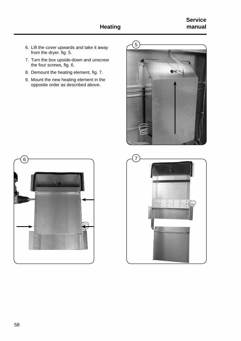
6. Lift the cover upwards and take it away from the dryer. fig. 5.
7. Turn the box upside-down and unscrew the four screws, fig. 6.
8. Demount the heating element, fig. 7. 9. Mount the new heating element in the
opposite order as described above.
5
6 7
59
HeatingServicemanual
Gas heated dryers
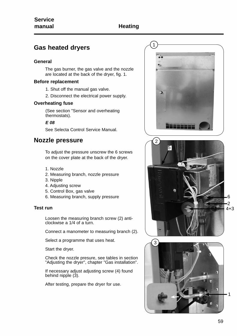
GeneralThe gas burner, the gas valve and the nozzle are located at the back of the dryer, fig. 1.
Before replacement 1. Shut off the manual gas valve. 2. Disconnect the electrical power supply.
Overheating fuse (See section "Sensor and overheating thermostats). E 08
See Selecta Control Service Manual.
Nozzle pressure
To adjust the pressure unscrew the 6 screws on the cover plate at the back of the dryer.
1. Nozzle 2. Measuring branch, nozzle pressure 3. Nipple 4. Adjusting screw 5. Control Box, gas valve 6. Measuring branch, supply pressure
Test run
Loosen the measuring branch screw (2) anti- clockwise a 1/4 of a turn. Connect a manometer to measuring branch (2).
Select a programme that uses heat.
Start the dryer.
Check the nozzle presure, see tables in section "Adjusting the dryer", chapter "Gas installation".
If necessary adjust adjusting screw (4) found behind nipple (3).
After testing, prepare the dryer for use.
1
24+3
52
3
1
6
HeatingServicemanual
60
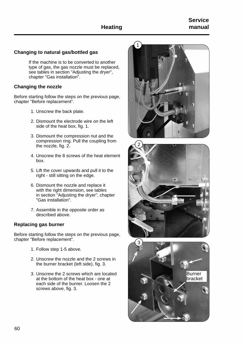
Changing to natural gas/bottled gas If the machine is to be converted to another type of gas, the gas nozzle must be replaced, see tables in section "Adjusting the dryer", chapter "Gas installation". Changing the nozzle
Before starting follow the steps on the previous page, chapter "Before replacement".
1. Unscrew the back plate.
2. Dismount the electrode wire on the left side of the heat box, fi g. 1.
3. Dismount the compression nut and the compression ring. Pull the coupling from the nozzle, fi g. 2.
4. Unscrew the 8 screws of the heat element box.
5. Lift the cover upwards and pull it to the right - still sitting on the edge.
6. Dismount the nozzle and replace it with the right dimension, see tables in section "Adjusting the dryer", chapter "Gas installation".
7. Assemble in the opposite order as described above.
Replacing gas burner
Before starting follow the steps on the previous page, chapter "Before replacement".
1. Follow step 1-5 above.
2. Unscrew the nozzle and the 2 screws in the burner bracket (left side), fi g. 3.
3. Unscrew the 2 screws which are located at the bottom of the heat box - one at each side of the burner. Loosen the 2 screws above, fi g. 3.
Burner bracket
1
2
3

61
HeatingServicemanual
4. On the right side of the heat box unscrew the 2 screws which are located at the bottom of the heat box. Loosen the 2 screws above, fi g. 1.
5. Pull out the gas burner and replace it.
6. Assemble in the opposite order as described above.
Replacing the Gas valve
Before starting follow the steps on the previous page, chapter "Before replacement".
1. Dismount the electrode wire on the left side of the heat box, see previous page.
2. Loosen the compression nut, fi g. 2.
3. Dismount the earth conductors on the valve, fi g. 3.
4. Unscrew the control box lid and pull out the box, fi g. 3.
5. Unscrew the 2 screws and pull out the gas valve and mount the new valve.
6. Assemble in the opposite order as described above.
Control box
Earth conductors
1
2
43

HeatingServicemanual
62
Replacing the ignition electrode/fl ame sensor
Before starting follow the steps on the previous page, chapter "Before replacement".
Ignition electrolde
1. Disconnect the ignition electrode which is located on the left side of the heat box. 2. Unscrew the 2 screws and pull out the ignition electrode and replace it, fi g. 1.
Flame sensor
1. Disconnect the ignition electrode which is located on the right side of the heat box. 2. Unscrew the 2 screws and pull out the fl ame sensor and replace it, fi g. 2.
.
2
1
63
HeatingServicemanual
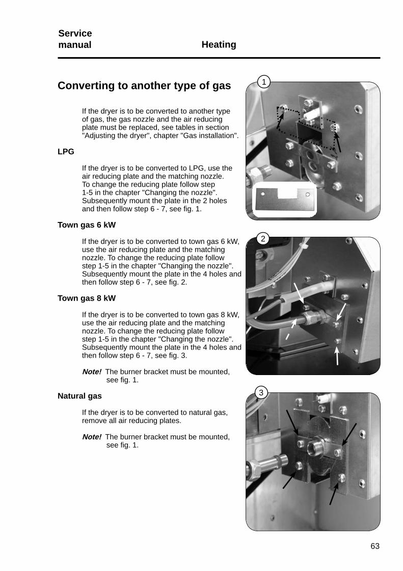
Converting to another type of gas
If the dryer is to be converted to another type of gas, the gas nozzle and the air reducing plate must be replaced, see tables in section "Adjusting the dryer", chapter "Gas installation".
LPG If the dryer is to be converted to LPG, use the air reducing plate and the matching nozzle. To change the reducing plate follow step 1-5 in the chapter "Changing the nozzle". Subsequently mount the plate in the 2 holes and then follow step 6 - 7, see fi g. 1.
Town gas 6 kW
If the dryer is to be converted to town gas 6 kW, use the air reducing plate and the matching nozzle. To change the reducing plate follow step 1-5 in the chapter "Changing the nozzle". Subsequently mount the plate in the 4 holes and then follow step 6 - 7, see fi g. 2.
Town gas 8 kW
If the dryer is to be converted to town gas 8 kW, use the air reducing plate and the matching nozzle. To change the reducing plate follow step 1-5 in the chapter "Changing the nozzle". Subsequently mount the plate in the 4 holes and then follow step 6 - 7, see fi g. 3.
Note! The burner bracket must be mounted, see fi g. 1.
Natural gas
If the dryer is to be converted to natural gas, remove all air reducing plates.
Note! The burner bracket must be mounted, see fi g. 1.
1
2
3
HeatingServicemanual
64
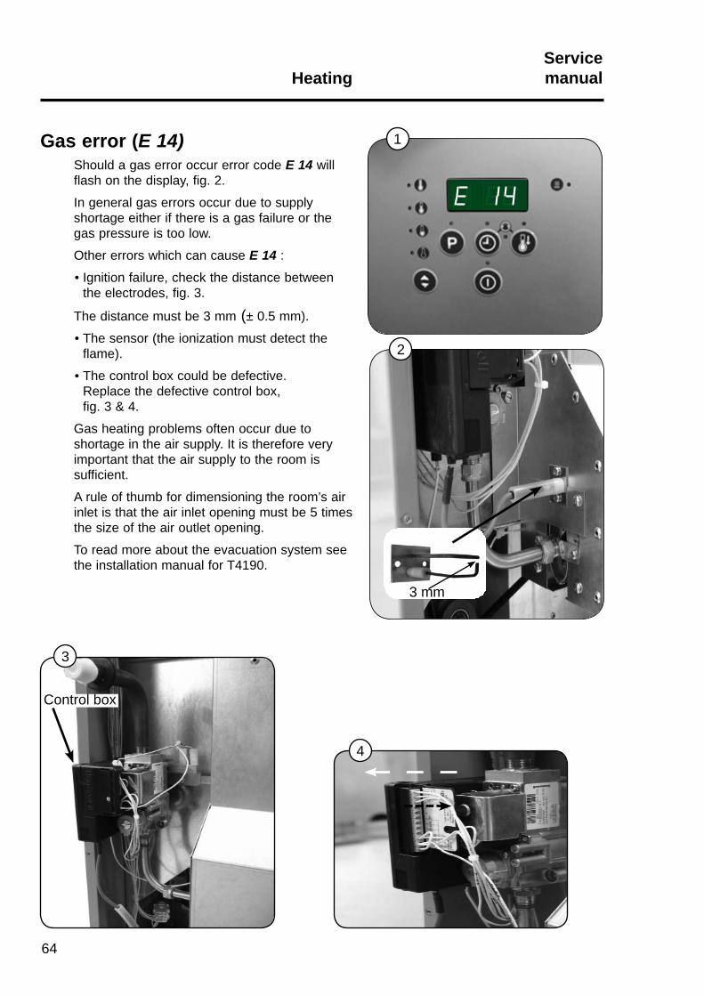
Gas error (E 14)Should a gas error occur error code E 14 willflash on the display, fig. 2.
In general gas errors occur due to supply shortage either if there is a gas failure or the gas pressure is too low.
Other errors which can cause E 14 :
• Ignition failure, check the distance between the electrodes, fig. 3.
The distance must be 3 mm (± 0.5 mm).
• The sensor (the ionization must detect the flame).
• The control box could be defective. Replace the defective control box, fig. 3 & 4.
Gas heating problems often occur due to shortage in the air supply. It is therefore very important that the air supply to the room is sufficient.
A rule of thumb for dimensioning the room’s air inlet is that the air inlet opening must be 5 times the size of the air outlet opening.
To read more about the evacuation system see the installation manual for T4190.
3 mm
Control box
2
1
4
3
1
2
65
HeatingServicemanual
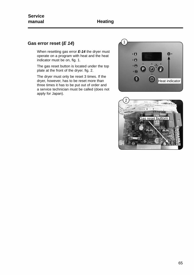
Gas error reset (E 14)
When resetting gas error E-14 the dryer must operate on a program with heat and the heat indicator must be on, fig. 1.
The gas reset button is located under the top plate at the front of the dryer. fig. 2.
The dryer must only be reset 3 times. If the dryer, however, has to be reset more than three times it has to be put out of order and a service technician must be called (does not apply for Japan).
Heat indicator
Gas reset buttom

66
67
Drum with bearingServicemanual
Content
Drum with bearing. . . . . . . . . . . . . . . . . . . . . . . . . . . . . . . . . . . . . . . . . . . 68
Replacing supporting rollers, bearing or drum . . . . . . . . . . . . . . . . . . . . . 68
1
A
Drum with bearingServicemanual
68
1
2
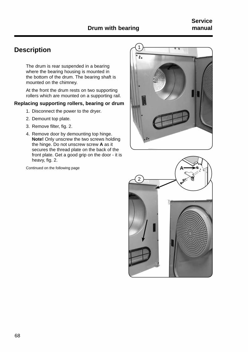
Description
The drum is rear suspended in a bearing where the bearing housing is mounted in the bottom of the drum. The bearing shaft is mounted on the chimney.
At the front the drum rests on two supporting rollers which are mounted on a supporting rail.
Replacing supporting rollers, bearing or drum1. Disconnect the power to the dryer.2. Demount top plate.3. Remove filter, fig. 2.4. Remove door by demounting top hinge.
Note! Only unscrew the two screws holding the hinge. Do not unscrew screw A as it secures the thread plate on the back of the front plate. Get a good grip on the door - it is heavy, fig. 2.
Continued on the following page

69
Drum with bearingServicemanual
3
4
Replacing supporting rollers, bearing or drum(continued from the previous page)
5. Demount front plade by removing, fig. 3: 8 covering buttons 12 screws 2 clips securing the panelRemove door switch wires and Control PCB.
6. Loosen the supporting rail with supporting rollers by unscrewing the 4 screws in the sides, fig. 4.
7. When replacing the supporting rollers demount the shaft screws from the supporting rail by unscrewing the nuts, fig. 4.
Continued on the following page

Drum with bearingServicemanual
70
6 7
8
Replacing supporting rollers, bearing or drum(continued from the previous page)
8. Demount bearing cover and center screw with disc, fig. 5.
9. Remove the big belt around the drum disengaging it from the drum, fig. 6.
10.Lift the collector graphites from the drum and fixate them in a position disengaging from the drum.
11.Carefully pull the drum out, fig. 7.12.When replacing the bearing unscrew the
three nuts. Bearing housing with bearing and triangular plate are loosened from the bottom of the drum, fig. 8.
Continued on the following page.
5

71
Drum with bearingServicemanual
Replacing supporting rollers, bearing or drum(continued from the previous page)
13. Mount in opposite order. Note! Before replacing the drum: • Make sure the collector graphies are still fixed in a retracted position. • The big belt must be positioned loosely in the back of the cabinet so it can be moved
freely over the drum. • Be careful if there is an RMC connector and wire on the drum casing. If necessary
protect them with tape mounting and positioning the drum in the dryer.

72

73
Cabinet, door reversalServicemanual
Contents
Reversing door . . . . . . . . . . . . . . . . . . . . . . . . . . . . . . . . . . . . . . . . . . . 74
1
1
2
3
Cabinet, door reversalServicemanual
74
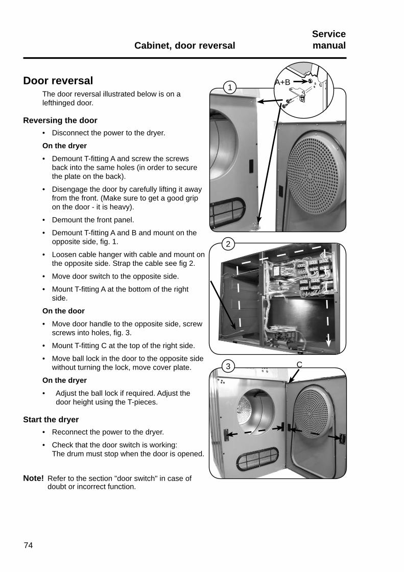
Door reversalThe door reversal illustrated below is on a lefthinged door.
Reversing the door• Disconnect the power to the dryer.
On the dryer• Demount T-fi tting A and screw the screws
back into the same holes (in order to secure the plate on the back).
• Disengage the door by carefully lifting it away from the front. (Make sure to get a good grip on the door - it is heavy).
• Demount the front panel.
• Demount T-fi tting A and B and mount on the opposite side, fi g. 1.
• Loosen cable hanger with cable and mount on the opposite side. Strap the cable see fi g 2.
• Move door switch to the opposite side.
• Mount T-fi tting A at the bottom of the right side.
On the door• Move door handle to the opposite side, screw
screws into holes, fi g. 3.
• Mount T-fi tting C at the top of the right side.
• Move ball lock in the door to the opposite side without turning the lock, move cover plate.
On the dryer• Adjust the ball lock if required. Adjust the
door height using the T-pieces.
Start the dryer• Reconnect the power to the dryer.
• Check that the door switch is working:The drum must stop when the door is opened.
A+B
C
Note! Refer to the section "door switch" in case of doubt or incorrect function.
75
RMCServicemanual
Content
RMC general . . . . . . . . . . . . . . . . . . . . . . . . . . . . . . . . . . . . . . . . . . . . . . 76

RMCServicemanual
76
1RMC generalRMC is a measuring method used to stop the dryer when the garments are dry.
The current dryness/moisture of the garments is continuously measured and the drying sequence is brought to an end when the pre-set level has been obtained.
The measuring signal is collected from the steel bands by means of the collector graphies which conduct the measuring signal to the Process Module.
One of the collector graphies is connected to a lifter and the other one to the drum casing. A weak measuring current is sent through the garments which are in touch with the lifter, and as the resistance increases gradually as the garments are getting more and more dry the measuring signal is ready for onward processing by the Control PCB.
Replacing collector graphies1. Demount top plate.
2. Replace collector graphies fig. 2.
2