
CMYK
CMYK
The Intelligent Simplicity
Air Circuit Breaker
Sentron 3WL
Answers for industry.Product upgradation is a continuous process.
Hence, data in this flyer is subject to change
without prior notice. For the latest information,
please get in touch with our Sales Offices.
Chennai4, Mahatma Gandhi Road, Chennai - 600034( : +91 44 28334000Fax: +91 44 28334088
Coimbatore7th Floor, East Wing, Global Towers1057, Avinashi Road, Coimbatore - 641018( : +91 422 4336300Fax: +91 422 4336310
Hyderabad5-9-19, Lakshmi Narsinh Estate, 4th FloorSecretariat Road, Opp. Secretariat, SaifabadHyderabad - 500004( : +91 40 23482500Fax: +91 40 23243145
Kolkata43 Shanti Palli, R B ConnectorEastern Metropolitan Bypass, Kolkata - 700042( : +91 33 24449000, 24428641-47Fax: +91 33 24449010 / 13
Lucknow28/45, Ashok Marg, Opposite Indira BhawanLucknow - 226001( : +91 522 4031022, 4031000Fax : +91 522 4031019
Mumbai130, Pandurang Budhkar Marg, WorliMumbai - 400018( : +91 22 24987000-02Fax: +91 22 24987312
Nagpur5th Floor, Landmark Building, Ramdas PethNagpur - 440010( : +91 712 6633000Fax: +91 712 6633111
New Delhi4A, Ring Road, I.P. Estate, New Delhi - 110002( : +91 11 42995000-09Fax: +91 11 42995030
PuneTower B / 701 - 705, ICC Trade Tower403A, Senapati Bapat Road, Pune - 411016( : +91 20 2570 6000Fax: +91 20 2570 6060
FaridabadHouse No 237, Sector-BFaridabad - 121006, HaryanaMobile: +91 987396350E-mail: [email protected]
Gurgaon 117-C, First Floor, Sector-30, Behind Jalvayu Vihar Gurgaon - 122001, HaryanaMobile: +91 9971091588E-mail: [email protected]
Guwahati G1, Hill View Apartment, Navagraha PathChenikuthi Hill Side, Guwahati - 781003, Assam( : +91 361 2663988Mobile: +91 9864037562E-mail: [email protected]: +91 9864110684E-mail: [email protected]
Hardwar 758, 1st Floor, Model Colony, Awas Vikas, Jwalapur Hardwar - 249407, UttarakhandMobile: +91 9897070133Fax: +91 1334 265491E-mail: [email protected]
Indore Indore - 452001, Madhya PradeshMobile: +91 9823011883E-mail: [email protected]
Jaipur 6, Park Street, Opp Pink City Petrol Pump, M.I.Road Jaipur - 302006, Rajasthan( : +91 141 2370274 / 2377956Fax: +91 141 2370482Mobile: +91 9829244313E-mail: [email protected]
Jalandar H.No 448R, First Floor, Pushpa NiwasNear Geeta Mandir, Model Town Jalandar - 144001, PunjabMobile: +91 9779194445E-mail: [email protected]
Jamshedpur 823, Udaigiri, Vijaya Heritage, Uliyan, Kadma Jamshedpur - 831005, Jharkhand( : +91 657 6451637Mobile: +91 9934311352E-mail: [email protected]
Jodhpur 371, Gauri House, Kamala Nehru NagarNear SBI Bank, Jodhpur - 342008, RajasthanMobile: +91 9828327200E-mail: [email protected]
Kanpur 106, Agarwal AparmentNear Hari Har Dham Mandir, Shyam Nagar Kanpur - 208013, Uttar Pradesh( & Fax: +91 512 2423348Mobile: +91 9839102434E-mail: [email protected]
Kolhapur B-7, Mahagaonkar Complex1147/E, Rajaram Road, Opp. Kamala CollegeKolhapur - 416001, Maharashtra( : +91 231 2536626Mobile: +91 9822558876E-mail: [email protected]
Kota 48, Model Town, Khedli Phatak Kota - 324002, RajasthanMobile: +91 9784842605E-mail: [email protected]
Ludhiana H.No 3746, First Floor, Sector 32-AChandigarh Road, Ludhiana - 141010, PunjabMobile: +91 9872317702E-mail: [email protected]
Ludhiana H.No 92, Lajpat Nagar, Near Bus StandLudhiana - 141010, Punjab( : +91 161 2770574Mobile: +91 9815502480E-mail: [email protected]
Madurai 8/12, Ground Floor, Sakhti Vellammal StreetSS Colony, Madurai - 625010, TamilnaduMobile : +91 9894617780E-mail: [email protected]
Nashik Flat No 2, Shivam Park, Rajiv NagarRane Nagar, Nasik-Mumbai HighwayNashik - 422009, MaharashtraMobile: +91 9822193204E-mail: [email protected]
Pondicherry 32, Second Floor, St. Theresa StreetPondicherry - 605001( : +91 413 4500101Mobile: +91 9840472727E-mail: [email protected]
Raipur Flat No.103, First Floor, Block B, Shilp EnclaveNear LAS Colony, Shankar Nagar Raipur - 492007, ChhattisgarhMobile: +91 9425057945E-mail: [email protected]
Rajkot D-3 Aalap Century, University RoadRajkot - 360005, GujaratMobile: +91 9825506962E-mail: [email protected]
Ranchi H-1/187, Harmu Housing Colony, HarmuRanchi - 834002, JharkhandMobile: +91 9234610953E-mail: [email protected]
Renukoot Above ICICI Prudentail Office, Patel NagarMurdhawa, Dist-SonebhadraRenukoot - 231217, Uttar PradeshMobile: +91 9838007897E-mail: [email protected]
Rourkela T-15, Civil Town, Rourkela - 769004, Orissa( : +91 661 2400880Mobile: +91 9437041724E-mail: [email protected]
Salem 3/25 Santosh Nagar, PACB BacksideChinnathirupathi, Salem - 636008, TamilnaduMobile: +91 9894617772E-mail: [email protected]
Sambalpur Pradhan Para, Near Jamkani MandirBeside LIC Div Off, AinthapalliSambalpur - 768004, Orissa( : +91 663 2541258Mobile: +91 9438529778E-mail: [email protected]
Surat 59, Ground Floor, Shreejinagar Part-1Dhabholi Char Rasta, Ved Road, KatagramSurat - 395004, GujaratMobile: +91 9925001779E-mail: [email protected]
Tiruchirappali T3, 3rd Floor, Vishranthi Daffodils ApartmentsOld Friends Eye Hospital, PuthurTiruchirappali - 620017, Tamilnadu( & Fax: +91 431 4030390Mobile: +91 9444911221E-mail: [email protected]
Trivandrum Sonu, TC9/2082, 5, Thamarakulam LaneSathamangalam, Trivandrum - 695010, KeralaMobile: +91 9895979604E-mail: [email protected]
Udaipur 303, Oasis Park, PP Singhal Marg, AmbavgarhUdaipur - 313001, Rajasthan( & Fax: +91 294 2430345Mobile: +91 9829039120E-mail: [email protected]
Vapi Flat No. 302, Samrajya IV, Royal ResidencyCharwada Road, Vapi - 396195, Gujarat( : +91 260 6451156Mobile: +91 9825147957E-mail: [email protected]
Vijayawada G-2,Shreya Tower, MoghalrajapuramNear Jammichettu CentreVijayawada - 520010, Andhra Pradesh( : +91 866 6629933Mobile: +91 9866463639E-mail: [email protected]
Visakhapatanam 84, Mount Moriah Residency, Waltair UplandsVisakhapatanam - 530003, Andhra Pradesh( : +91 891 2712535Mobile: +91 9849212555E-mail: [email protected]
Order No.: 102276646
SGR-01-115-023(This replaces SGR-01-115-008)
Customer Care Toll free no. 1800 220 987
Email: [email protected]

CMYK
CMYK
The Art of Intelligent Simplicity - Sentron WL
Circuit Breakers today are no longer simple
switching and protecting devices with ON/OFF
and trip indications. Users today are looking at
circuit breakers as a device, which integrates
switching, protection, metering and power
management including quality of power from
remote locations. Modern power systems are
also characterized by the methods used to
network circuit breakers - both with each
other and with other components.
Intelligent Modularity with Cost Savings:
• Same internal and external accessories for the entire range reducing inventory cost.
• Compact in size. A 6300 A 3WL requires only 800mm wide cabinet.
• Practically no deration till 55 Deg C with the permissible service temperature upto 70 Deg C. A 5000 A 3WL can deliver 5000 Amp even at 70 Deg C.
• High electrical life reduces the frequency of replacement of contacts.
• Unique rating plug facility allows a 3200 Amp 3WL to have thermal overload setting as low as 100A. This ensures complete protections even when the system is partially loaded.
Siemens offers SENTRON WL family, which
have a lot more to offer than even the so-
called “new circuit breaker” in the market. In
future, it will not only be possible to carry out
diagnosis and maintenance procedures
remotely on the Internet, but real-time
information about system malfunctions and
alarm signals will be made available
immediately to operating staff through SMS
and mobile phones.
This is not a fantasy for the future; in fact it’s hard reality.
This is Sentron. A new generation of circuit breakers from 100 A to 6300 A available in three
different sizes with the following advantages.
• Integrated CubicleBUS provides unmatched flexibility and cost economic solutions to all panels - metering, protections and annunciations requirements.
• Sentron stands for complete energy management - solution for continuous energy cost supervision and optimization - in short intelligent savings.
“SENTRON - Intelligent Simplicity”
In essence, modularity means: User-friendly
ease of planning, multiple use of standard
configurations - also, simple management of
changes and modification on site
2
The two available waveform buffer enable currents and voltages to be recorded on an event controlled basis.
31
CMYK
CMYK
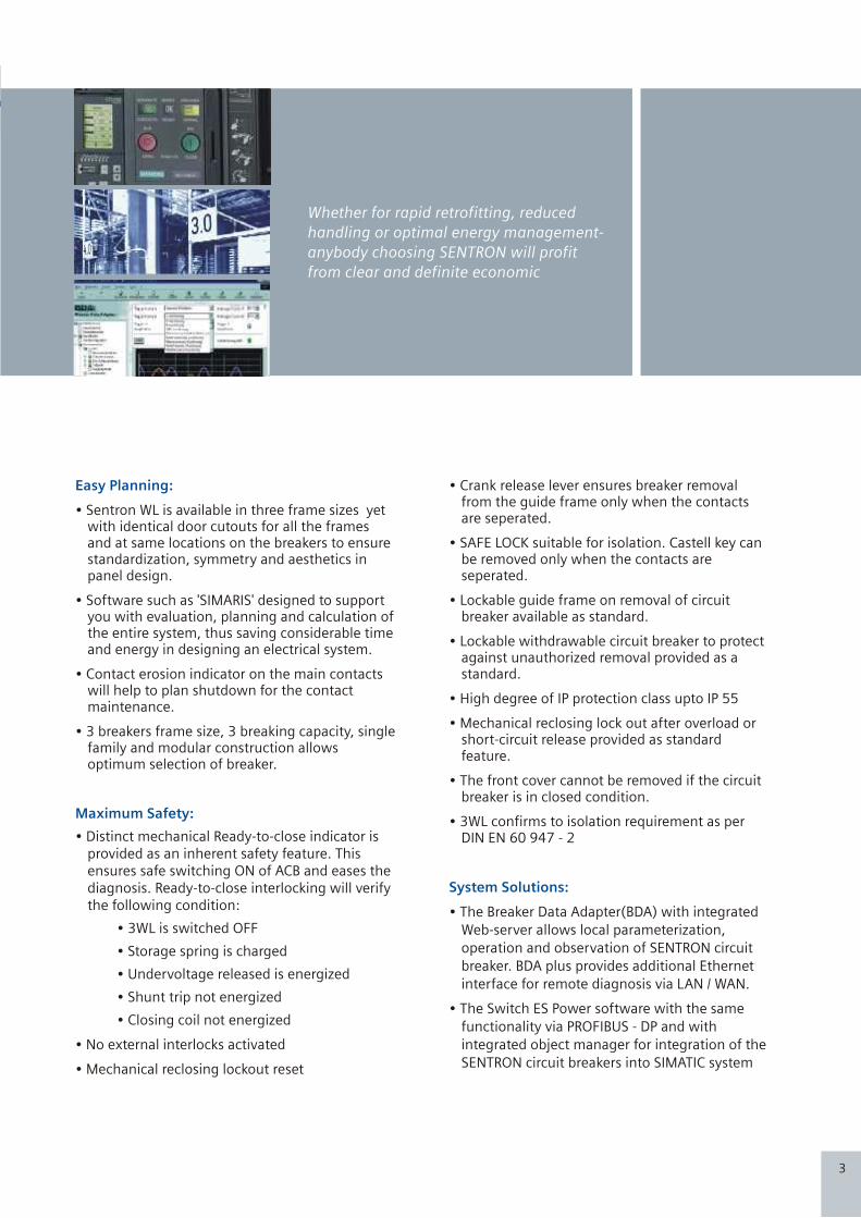
Whether for rapid retrofitting, reduced
handling or optimal energy management-
anybody choosing SENTRON will profit
from clear and definite economic
Easy Planning:
Maximum Safety:
• Sentron WL is available in three frame sizes yet with identical door cutouts for all the frames and at same locations on the breakers to ensure standardization, symmetry and aesthetics in panel design.
• Software such as 'SIMARIS' designed to support you with evaluation, planning and calculation of the entire system, thus saving considerable time and energy in designing an electrical system.
• Contact erosion indicator on the main contacts will help to plan shutdown for the contact maintenance.
• 3 breakers frame size, 3 breaking capacity, single family and modular construction allows optimum selection of breaker.
• Distinct mechanical Ready-to-close indicator is provided as an inherent safety feature. This ensures safe switching ON of ACB and eases the diagnosis. Ready-to-close interlocking will verify the following condition:
• 3WL is switched OFF
• Storage spring is charged
• Undervoltage released is energized
• Shunt trip not energized
• Closing coil not energized
• No external interlocks activated
• Mechanical reclosing lockout reset
• Crank release lever ensures breaker removal from the guide frame only when the contacts are seperated.
• SAFE LOCK suitable for isolation. Castell key can be removed only when the contacts are seperated.
• Lockable guide frame on removal of circuit breaker available as standard.
• Lockable withdrawable circuit breaker to protect against unauthorized removal provided as a standard.
• High degree of IP protection class upto IP 55
• Mechanical reclosing lock out after overload or short-circuit release provided as standard feature.
• The front cover cannot be removed if the circuit breaker is in closed condition.
• 3WL confirms to isolation requirement as per DIN EN 60 947 - 2
• The Breaker Data Adapter(BDA) with integrated
Web-server allows local parameterization,
operation and observation of SENTRON circuit
breaker. BDA plus provides additional Ethernet
interface for remote diagnosis via LAN / WAN.
• The Switch ES Power software with the same
functionality via PROFIBUS - DP and with
integrated object manager for integration of the
SENTRON circuit breakers into SIMATIC system
System Solutions:
3
Advantages through Siemens SENTRON Communication:
Startup and Configuration:
Operator Control and Monitoring:
Power Management:
Maintenance and Service:
• PROFIBUS-DP enables faster and more reliable connections than conventional
point-to-point wiring. (Option with MODBUS also)
• Minimum plant down times for necessary expansion
• Simple startup test
• Transparent startup process with good documentation options
• Fast and reliable local configuration via PROFIBUS-DP or MODBUS or the Ethernet
/ Intranet / Internet with intelligent configuration software.
• Increase transparency in power distribution through transmission of current status
information, alarm signals and set point monitoring.
• Fault management enables a fast response when leaving the normal state.
Important message (e.g. trip signal and reasons) can be transmitted by SMS to the
cell phone of the plant personnel.
• Options for the central readout of parameters and their automatic transmission to
interchangeable circuit breakers minimizes fault liability and shortens down times.
• Effective diagnostics management e.g. through determinations of the precise
cause of fault and recording of the phase current.
• Remote control of the circuit breaker enables both the manual and automatic
switching on and off of plant parts.
• The balancing of load peaks and troughs allows the realization of energy imports
costs. Efficient load management enables the demand-orientated switching.
• Analysis of the archived power values (output curves) enables creation of a power
consumption profile. This can be the basis for future power procurement.
• The quality of energy (harmonics, flickers) can be logged and documented. This
enables effective power quality management.
• Cost center management makes power consumption more transparent for
commercial analysis. Cost can be clearly assigned and optimized.
• Information for preventive maintenance (e.g. number of switching operations,
operating hours, contact erosion estimation) enables timely and calculated
planning of necessary maintenance work. This reduces the risk of costly damage
to sensitive plant parts.
• The central control of maintenance work and the ability to SMS key information
considerably reduce costs for maintenance and service.
30

CMYK
CMYK
Data that can be transmitted using COM15 / COM16or the breaker data adapter
Order code (Order no. Of circuit breaker + “-Z” )Order no.
Transmission of circuit breaker data to PROFIBUS-DP or Modbus - TCP / IP Network and Integration in higher-level visualization system possible e.g. In PCS7 Power Management Systems, WinCC (Incl. Add Ons, such as SMS radio server)
Transmission of circuit breaker data and software (i.e. HTML pages Incl. Data) to local output device or remotely controlled via the Ethernet/Intranet/Internet (no Integration option in higher-level visualization systems) e.g. for monitoring diagnostics, maintenance and configuration of individual circuit breaker
Use of the functionality of all CubicleBUS modulesE.g. Programming of the configurable digital output modules, status interrogation of digital input modules diagnostics, testing
Device Identification:Communication address, circuit breaker order no., Circuit breaker characteristic data (Size no. Of poles, rated current module etc.) ID numbers, release type, free text for equipment identifier and comments
Operating states:Closed / open signal spring store mechanism, tripped, readiness to close, Circuit breaker position (connected, test, disconnected and absent) for withdrawable circuit-breakers, PROFIBUS write protection on/off, free user input
Control commandsClosed / open circuit breakers, enable/disable free user output Reset trip signalClear event and trip logReset the min/max measured values, reset maintenance information
HistoryReadout of event log, readout of trip log
Maintenance InformationNumber of L, S, I releases and total, contact erosionNumber of switch operations under load and total operating hours
Event signaling Trip signal with identificatio of the current casuing the tripAlarm signaling (e.g. Overload) with incoming/outgoing informationAll named event signaling with time stamp
Configuration of protective functionsReadout of protective function parametersChange the settings of the protective function parameters through communication Parameter set changeover option (set A to set B)
Measured valuesPhase currents, each with min/max, valueTemperature in the circuit breaker with min/max. value Temperature in the cubicle with min/max, valueAll named measured values with time stamp
Additional transmittable circuit breaker data with integrated metering functions as mentioned on page 24, 25 & 26
+BDA/BDA Plus order no.
1)
1)
1)
1)
1)
1)
1)
2) 2)
1) Possible in connections with the COM15 / COM16 Module (Bus connection not required)
*
2) Possible with ETU 76B*
29
F01
BSS BSS COM15 / COM16 BDA
F02/F12
Transmittable circuit breaker data without integrated metering function
Application options
Transmittable circuit breaker data

CMYK
CMYK
User-friendly and precise:Planning with SENTRON
Standards:- The Sentron WL Circuit Breakers satisfy:
! IEC 60947 - 2, IS 13947 - 2
! DIN VDE 0660 Part 101
! UL 489 / ANSI C 37.13, UL 1066
! Climate Proof according to DIN IEC 68 Part 30 - 2
! CE Conformance
! Lloyd’s Register of shipping
5
Breaker Data Adapter BDA:
Switch ES Power:
Power Management:
The BDA is the first circuit breaker parameterisation device with integrated web server for the local programming, operation and monitoring of the SENTRON WL and SENTRON VL. The data may be read out on any output device with browser capabilities(e.g. Notebook), without the need for special software. The only system requirement for the input / output device is a standard browser with JAVA2 virtual machine. Once the BDA is connected to the circuit breaker, the browser is filled with Web pages from BDA and the data of the circuit breaker as shown in the following pictures. In addition, the BDAPlus incorporates an Ethernet interface for direct connection to the Ethernet/Intranet/Internet.
By means of the Switch ES Power software, the SENTRON WL and SENTRON VL circuit breakers can be parameterized, operated and monitored via PROFIBUS-DP. Operational philosophy of switches has been harmonized with that of the BDA. An object manager ensures complete integration into the SIMATIC world. Thus, SENTRON becomes an important component in Totally Integrated Automation(TIA).
SENTRON circuit breakers can be easily integrated into Power Management Systems. This facilitates efficient diagnosis, alarm, maintenance, cost center and load management. SENTRON circuit breakers play a key role in solutions provided by Totally Integrated Power(TIP).
Breaker Data Adapter - diagnostics
Cubicle BUS SENTRON WL
SENTRON VL
Modem
Modem
Notebook
You can use modems to extend the serial connection from the notebook to the BDA to enable the circuit breaker data to be accessed irrespective of your geographical location
28
CMYK
CMYK
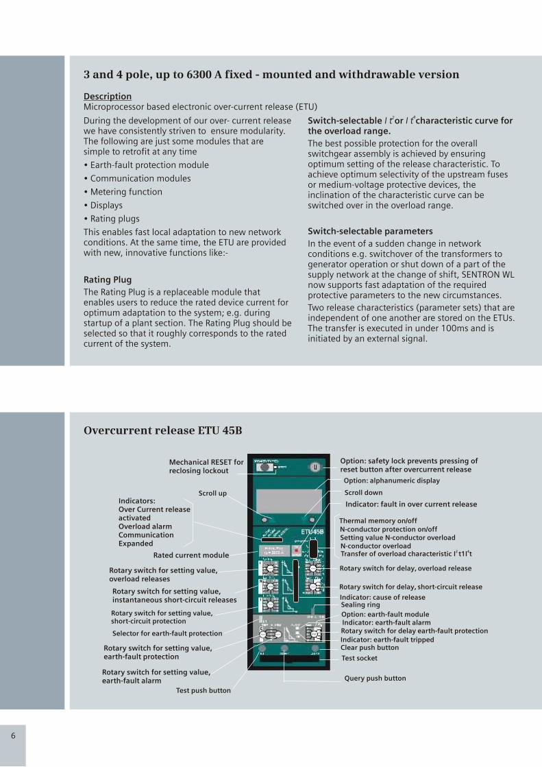
Mechanical RESET for reclosing lockout
Rated current module
Rotary switch for setting value, overload releases
Rotary switch for setting value, instantaneous short-circuit releases
Rotary switch for setting value, short-circuit protection
Selector for earth-fault protection
Rotary switch for setting value, earth-fault protection
Rotary switch for delay earth-fault protection
Rotary switch for delay, short-circuit release
Rotary switch for delay, overload release
N-conductor overload
N-conductor protection on/off
Indicator: fault in over current release
Scroll down
Option: alphanumeric display
Option: safety lock prevents pressing of reset button after overcurrent release
Thermal memory on/off
Setting value N-conductor overload
2 4Transfer of overload characteristic I t1I t
Indicator: earth-fault tripped
Indicator: earth-fault alarm
Indicator: cause of release
Option: earth-fault module
Sealing ring
Rotary switch for setting value, earth-fault alarm
Test push button
Query push button
Clear push button
Test socket
Indicators:Over Current release activatedOverload alarmCommunicationExpanded
Scroll up
Overcurrent release ETU 45B
During the development of our over- current release we have consistently striven to ensure modularity. The following are just some modules that are simple to retrofit at any time
• Earth-fault protection module
• Communication modules
• Metering function
• Displays
• Rating plugs
This enables fast local adaptation to new network conditions. At the same time, the ETU are provided with new, innovative functions like:-
Rating Plug
The Rating Plug is a replaceable module that enables users to reduce the rated device current for optimum adaptation to the system; e.g. during startup of a plant section. The Rating Plug should be selected so that it roughly corresponds to the rated current of the system.
Switch-selectable or I t characteristic curve for the overload range.
The best possible protection for the overall switchgear assembly is achieved by ensuring optimum setting of the release characteristic. To achieve optimum selectivity of the upstream fuses or medium-voltage protective devices, the inclination of the characteristic curve can be switched over in the overload range.
Switch-selectable parameters
In the event of a sudden change in network conditions e.g. switchover of the transformers to generator operation or shut down of a part of the supply network at the change of shift, SENTRON WL now supports fast adaptation of the required protective parameters to the new circumstances.
Two release characteristics (parameter sets) that are independent of one another are stored on the ETUs. The transfer is executed in under 100ms and is initiated by an external signal.
I t2 4
DescriptionMicroprocessor based electronic over-current release (ETU)
3 and 4 pole, up to 6300 A fixed - mounted and withdrawable version
6
Waveform Memories:
The metering function Plus offers two additional functions:
• Two independent waveform memories.
• Harmonic analysis.
The two independent waveform memories can be used to analyze the current and voltages values at the time of the event.
The waveform memories can also be started or stopped individually through the communications channels (PROFIBUS-DP, MODBUS and Cubicle BUS).
Currents I L1, I L 2 , I L 3, I L N , I g
Voltages UL1; UL2: Ul3
The values that can be selected for one of the waveform memories are:
If the waveform memories are programmed to "recording" (standard setting), there is continuous recording until a previously defined event occurs. Then, the recording is stopped, and the current or voltage waveforms at the time of the event can be observed through a visual display (graphical LCD, laptop or PC). The time window is one second; the resolution is 1649 values/second.
27
CMYK
CMYK
Application:
Properties:
Cost-effective intelligent allrounder for building and
all types of industrial applications- ”Cubicle BUS
integrated”.
1. Adjustable time-lag class for overload protection
2. Short-time delayed short-circuit protection,
adjustable from 1.25... 12 x I n
3. Instantaneous short-circuit protection adjusting
12 I /Max/Offn
4. Replaceable Rating Plug allows instant
adaptability to required plant currents, thus
ensuring overload protection of 100 A to 6300 A.
5. Switch-selectable characteristic of the overload
and short-time delay short-circuit range (current
discriminate) for finer selectivity conditioning to
downstream fuses or protective devices
6. Thermal memory as restart protection in case of
tripped motor circuits
7. Connectable and adjustable neutral conductor
protection
8. Modular earth-fault protection, with separately
adjustable alarm and trip function
9. Communication interface, metering function
(Plus), connection of external modules as option
or retrofit option.
10. Optional high-contrast display with viewing
angle adjustment
11. Overload indicator
12. Display of cause of trip through LED
13. Option for testing the release
14. Setting of protective functions by means of
rotary or slide switch.
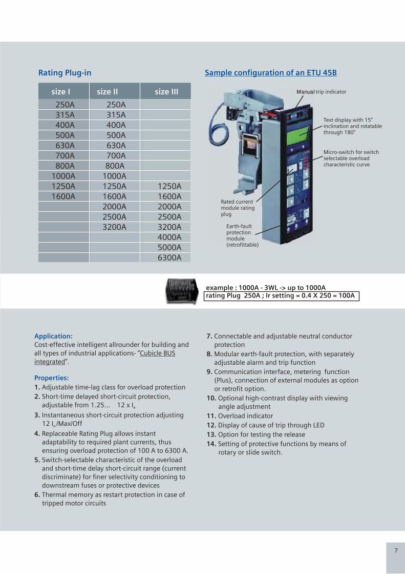
example : 1000A - 3WL -> up to 1000Arating Plug 250A ; Ir setting = 0.4 X 250 = 100A
Sample configuration of an ETU 45B
Manual trip indicator
Text display with 15”inclination and rotatablethrough 180”
Micro-switch for switchselectable overloadcharacteristic curve
Rated currentmodule ratingplug
Earth-faultprotection module(retrofittable)
Rating Plug-in
7
250A 250A
315A 315A
400A 400A
500A 500A
630A 630A
700A 700A
800A 800A
1000A 1000A
1250A 1250A 1250A
1600A 1600A 1600A
2000A 2000A
2500A 2500A
3200A 3200A
4000A
5000A
6300A
size I size II size III
Setpoints:
The metering function PLUS provides Setpoint Function for automatic monitoring of operating conditions and generating warnings on violation to set threshold values. These can be communicated on the CubicleBUS and transferred via COM15. Please Note: violation of setpoint values never sends tripping signal to ETU.
Parameters
Phase overcurrent
grond overcurrent
neutral overcurrent
phase current unbalance
current demand
under voltage
phase voltage unbalance
over voltage
over power in normal direction
kW reverse
kW demand
kVA demand
kVAR demand
KVAR consumed
KVA
over frequency
under frequency
under power factors
over power factor
current THD
voltage THD
crest factor
form factor
Range
30 ……. 10000 A
30 ……. 10000 A
30 ……. 10000 A
5 …..50%
30 ……10000 A
15 …… 1200 V
5 …. 50%
15 ….. 1200 V
13 …… 10000 kW
13 …… 10000 kW
13 ……. 10000 kW
13 ……. 10000 kVA
13 ……. 10000 kVar
13 ……. 10000 kVAR
13 ……. 10000 kVA
40 …. 70 Hz
40 ….. 70 Hz
0 …… + 0.99
0 …… - 0.99
5 …. 50%
5 …… 50%
1….3.000
1….3.000
Delay
1 ….. 255 s
1 ….. 255 s
1 ….. 255 s
1 ….. 255 s
1 ….. 255 s
1 ….. 255 s
1 ….. 255 s
1 ….. 255 s
1 ….. 255 s
1 ….. 255 s
1 ….. 255 s
1 ….. 255 s
1 ….. 255 s
1 ….. 255 s
1 ….. 255 s
1 ….. 255 s
1 ….. 255 s
1 ….. 255 s
1 ….. 255 s
5 …… 255 s
5 ……255 s
1 ….. 255 s
1 ….. 255 s
Extended Protective functions:
The Metering Function PLUS is used to
implement extended protective
functions beyond the functionality of
the overcurrent releases. If one of these
parameters exceeds or falls below its
default settings, the overcurrent release
is tripped if the set event persists longer
than the delay time.
Parameters
Under voltage pickup
Over voltage pickup
Active power in normal direction
Active power in reverse direction
Overfrequency pickup
Under frequency pickup
Phase current unbalnce pickup
Phase voltage unbalnce pickup
Phase rotation
Pickup THD current
Pickup THD volatge
Range
100 …. 1100 V
200 … 1200 V
13 …. 4000 kW
13 …. 4000 kW
40 … 70 Hz
40 ….70 Hz
5…. 50%
5….50%
5 …..50%
5 …..50%
Delay
1…. 15 s
1…..15 s
2 ….15 s
2 ….15 s
1….15 s
1….15 s
1….15 s
1….15 s
5 ….15 s
5 ….15 s
26

CMYK
CMYK
Overcurrent release ETU 76B
Mechanical RESET for reclosing lockout
Rated current module
Option: earth-fault module
Indicator: fault in overcurrent release
Indicator: cause of release
Graphical display
Control keys for setting the release parameters
Option: safety lock prevents pressing of reset button after overcurrent release
Earth-fault tripped
Indicator: Earth-fault alarm
Clear push button
Fields for noting setting values
Fields for noting setting values
Test socket
Test push button
Query push button
Indicators:Over Current release activatedOverload alarmCOMMUNICATION EXPANDED
Selection of the overcurrent releases
ETU 76B
ETU 45B
ETU 27B
ETU 25B
ETU 15B
8
Metering Function PLUS:
The integrated metering function can be used with all trip units, equipped with CubicleBUS interface. It is an interesting alternative to external multifunction metering devices. Measured values include currents, voltages, powers, energy, cos o and frequency.
The data can be shown on the display of the overcurrent releases, transmitted to the PROFIBUS-DP through the COM15(or MODBUS through COM16) and transferred to the outputs external CubicleBUS modules.
COM15 / COM16
By means of the PROFIBUS module COM15 or MODBUS module COM16 the circuit breakers can be connected directly to the PROFIBUS-DP or Modbus network. The COM modules support the innovative DPV1functions. This guarantee the simplest commissioning and diagnosis of the circuit-breaker as well as facilitates optimal visualization of the data.
Measured parameters
Currents I L1, IL2, IL 3, IN, Ig
Line Voltages VL12,VL23,VL31
Phase Volatage VL1N, VL2N, VL3N
Present average of line voltages V avg
Apparent Power SL1,SL2,SL3
Total apparent power
Active power PL1, PL2,PL3
Total active power
Total reactive power
Reactive power QL1, QL2,QL3
Power factor Cos Ø 1, Cos Ø 2, Cos Ø 3
Power factor total
Long term average of currents Il1, Il2, Il3
Long term average of 3-phase current
Long term average of active power in L1, L2, L3.
Long term average of active power 3 phase.
Long term average of apparent power in L1, L2, L3 and Total apparent power
Long term average of reactive power 3 phase.
Energy consumed
Energy delivered
Reactive energy consumed
Reactive energy delivered
Frequency
Distortion factor of current and voltage
Phase unbalance of current and voltage
Range
30 ….. 8000 A
15 …… 130V and 130 …. 1150 V
10….75V and 75….700 V
10….75V and 75 …700 V
13….8000 kVA
13…..24000kVA
-8000 ….+ 8000 kW
-24000 …. + 24000 kW
-20000 .... + 20000 kVar
-6400 ….. +6400 kVar
-0.6 …. 1 …. +0.6
-0.6 …. 1 …. +0.6
30 ……. 8000 A
30 ……. 8000 A
13 ……. 8000 kW
13 ……. 8000 kW
13 ……. 8000 kVA
- 8000 …… + 8000 kVar
1 …… 10000 MWh
1 …… 10000 MWh
1….. 10000 MVarh
1….. 10000 Mvarh
15 ……40 Hz40 ---- 70 Hz70 ---- 440 Hz
2 …. 100%
2 ….. 150%
Accuracy
+ 1% of measurement range.
+ 1% of measurement range.
+ 1% of measurement range.
+ 1% of measurement range.
+ 2% of measurement range.
+ 2% of measurement range.
+ 2% of apparent power ( cosØ > 0.6)
+ 2% of apparent power ( cosØ > 0.6)
+ 4% of apparent power
+ 2% of apparent power .
+ 4%
+ 4%
+ 1% of measurement range.
+ 1% of measurement range.
+ 2% of apparent power ( cosØ > 0.6)
+ 2% of measurement range.
+ 2% of measurement range.
+ 2% of apparent power .
+ 2%
+ 2%
+ 2%
+ 2%
+ 0.1 Hz
+ 2% of measurement range upto 29th harmonic
+ 1% of displayed value.
25

CMYK
CMYK
Application:
Properties:
The multitalent with graphical display for network analysis “CubicleBUS integrated”.
As for ETU45B plus the following:
1. Two protective parameter steps that can be stored seperately in the release (switch-selectable through external signal).
2. Overload protection that can be switched off for use with modern operating mechanism.
3. Adjustable lag of the delayed short-circuit protection up to 4000ms.
4. Neutral conductor protection adjustable to I = 2 In n .
5. Setting of protective functions by means of control keys or Breaker Data Adapter or through communication interface.
6. Graphical display of all parameters and event/curve characteristics.
7. Storage of events and causes of release for specific error analysis.
8. High-contrast background - lit graphical display with sleep mode.
Available not available optional
Ra
ng
es
/ F
un
ctio
ns
Ov
erl
oa
d p
rote
ctio
n
Sh
ort
-tim
e d
ela
ye
dsh
ort
-cir
cuit
pro
tect
ion
Inst
an
tan
eo
us
sho
rt-
circ
uit
pro
tect
ion
Pro
tect
ion
of
ne
utr
al co
nd
uct
or
Ea
rth
-fa
ult
p
rote
ctio
n
ZS
I (z
on
e-s
ele
ctiv
ein
terl
ock
ing
)
LCD
4 l
ine
s
LCD
gra
ph
ic
Co
mm
un
ica
tio
n v
iaP
rofi
bu
s D
P/M
OD
BU
S
Me
teri
ng
fu
nct
ion
s
Se
lect
ab
lep
ara
me
ter
sets
Fre
ely
pro
gra
mm
ab
lep
ara
me
ters
ETU 76B
ETU 45B
ETU 27B
ETU 25B
ETU 15B
9
The Cubicle BUS is the internal bus system, providing the interconnection between
all the intelligent components within the SENTRON WL (e.g. trip unit, Breaker
Status Sensor, metering function, communication module). It also permits the
simple connection of external accessory components (CubicleBUS Module, BDA
Plus) to the circuit-breaker. It is integrated as standard on all SENTRON WL circuit
breakers equipped with ETU45B and above.
External CubicleBUS Module:
By means of CubicleBUS, external accessory modules can be connected to the SENTRON WL with minimum wiring.
Available modules include: digital output modules, analog output modules, digital input modules as well as ZSI modules
for zone-selective interlocking. By using these accessories, one can save the need for similar discrete peripheral modules.
Digital input module
The digital input module supports connection of 6 additional binary signals (24V DC) within the circuit breaker environment to the system. This enables, for example, the status signaling of a switch disconnector or of a cubicle door to be transmitted to PROFIBUS-DP.With the digital input module on the Cubicle BUS, it is also possible to automatically switch the two different protective parameter set held in the ETU 55B. And ETU- 76B releases. This allows, among other things, the automatic changing of the parameters of a tie switch in the event of a power supply failure.
One module each of this type can be implemented for the input of the six digital signals and for the automatic switchover of the parameters.
ZSI module
If Siemens circuit-breakers are arranged in several levels and minimal delays are desired, it is advisable to use the ZSI module.
The circuit breakers are interconnected by these modules. In the event of a short-circuit all circuit breakers communicate to determine and isolate the exact short-circuit location. This way only the next upstream circuit breaker line energy flow direction will be opened.
Analog output moduleThe analog output module can be used to output the following measured values of the circuit breaker to analog display devices on the cubicle door
Digital output module configurableThe configurable output module is available for more powerful solutions.In this case, many events on the CubicleBUS can be directly switched to one of the six available outputs, or three of the outputs can be assigned up to six events, i.e. Up to six events can be applied to a single physical output with an “OR” logic operation. The configuration is executed either with BDA/BDA Plus or Switch ES Power. As with the output modules with rotary switch, an optocoupler and a relay variant are available.
Only one module of this type can be implemented through SENTRON WL.
Digital output module with rotary switch
6 binary signals on the breaker status(causes of trip and warning) can be output over this module to external signaling devices (e.g. Light, horn) or used to switch off of other specific plant parts (e.g. Frequency converter ) Digital output modules are available with or without rotart switches.
With rotary switch modules, you can choose between two signal blocks each with 6 defined assignment and an additional response delay. All digital output modules are available either as an optocoupler output (NO contact, 150 mA) or a relay output version (change-over, up to 12A). Two module of this type may be connected to a SENTRON WL.
Four 4-20-mA/0-10V interfaces are available for this purpose. The measured values to be output are selected with a rotary switch. This analog output module means there is no need for additional transformers requiring conventional installation/wiring in the main bus. Two modules of this type may be connected to a SENTRON WL.
• I , I , I , I orl1 L2 L3 N
• U , U U , U orL12 L23 L31 LIN
• P , P , P , S orl1 L2 L3 tot
• COS ,COS COS , I or1 2 3 %
• f , U , P , COS avg LLavg tot avg
24

CMYK
CMYK
SENTRON WL circuit-breakers with I = 1000 A and ETU 45B or ETU 55B
electronic release
Inverse-time delayed overload range L
.01
.1
1
10
100
100 1000 10000 100000
1000
10000
t [s
]
I [A]
SENTRON WL circuit-breakers with I = 1000 A and ETU 45B or ETU 55B
electronic release
Instantaneous short-circuit range l
.01
.1
1
10
100
100 1000 10000 100000
1000
10000
t [s
]
I [A]
SENTRON WL circuit-breakers with I = 1000 A and ETU 45B or ETU 55B
electronic release
Short-time delayshort-circuit range S l
.01
.1
1
10
100
100 1000 10000 100000
1000
10000
t [s
]
I [A]
SENTRON WL circuit-breakers with I = 1000 A and ETU 45B or ETU 55B
electronic release
Earth-fault protection range G
.01
.1
1
10
100
100 1000 10000 100000
1000
10000
t [s
]
I [A]
Tripping characteristics
Every release type and every setting has its
own characteristic. You will find just a small
selection of these illustrated below. The
characteristics show the respective greatest
and smallest setting range of SENTRON WL
circuit-breakers with 1000A rated current,
690V rated voltage with various releases.
The characteristics show the behavior of the
overcurrent release when it is activated by a
current already flowing before the release.
If the overcurrent release is not activated, the
opening time is prolonged up to 15ms,
depending on the value of the
overcurrent. To determine the total
break-times of the circuit-breakers about
15ms must be added to the displayed
opening times for the arc duration.
The displayed characteristics apply for
ambient temperature at the circuit-
breaker of -5 to +55 Deg C. The release
can be operated at ambient
temperatures of -20 to +70 Deg C.
2Inverse-time delayed overload range L I t=constant
2 4Overlapping of the Inverse-time delayed overload range L I t and I t
4Inverse-time delayed overload range L I = constant
Short-time delayed short-circuit range S
Instantaneous short-circuit range I
Earth-fault protection range G
You will find further characteristics in the manual or in the SIMARIS deSign planning and configuring tool Or if you have any further queries, please contact your partner.
10
SENTRON Communication Solution
23

CMYK
CMYK
Easy to Plan
Perfectly Modular
Circuit-breakers from
100A to 6300A
Simple planning with
SIMARIS design
Cost Saving
Simple, rapid retrofitting
Reduced parts variance
ONo derating till 55 C
High power rating - low
space requirement
11
SENTRON 3VL Circuit Breaker
Microprocessor based release with LCD
Microprocessor based release
COM10 PROFIBUS /COM11 MODBUS module with. ZSI
COM20 PROFIBUS /COM21 MODBUS module with. ZSI
Breaker Data Adapter (BDA)
BDA Plus with Ethernet Interface
Browser-capable input & output (e.g notebook)
SENTRON 3WL Circuit Breaker
COM 15 PROFIBUS / COM 16 MODBUS Module
Breaker Status Sensor (BSS)1) For a MODBUS connection the COM16 module is required
2) For a MODBUS connection the COM21 module is required
releaseMicroprocessor based
Metering function Plus
ZSI (Zone-Selective Interlocking) module
Digital output module as relay contacts
Digital output module as relay contacts, configurable
Analog output module
Digital input module
Switch ES Power on PC
PLC e.g. SIMATIC S7
Power Management System
Communication capable SENTRON Power Monitoring Devices
1
2
3
4
5
6
7
8
9
10
11
12
13
14
15
16
17
18
19
20
21
22
Technological leaders
amongst the Circuit breakers:
22
System Solutions
State-of-the-art
communication
Diagnosis also possible
via the Internet
Power Management

CMYK
CMYK
TOTALLY
INTEGRATED
POWER BY
Siemens
TOTALLY
INTEGRATED
AUTOMATION BY
Siemens
21
SENTRON WL: An air circuitbreaker family for the complete spectrum of power distribution whether in building infrastructure or industrial applications.
Rated current In at 55oC, at 50/60 Hz
Main conductor A up to 1000 1250 1600 800 1000 1250
N-conductor (only with 4 poles) A up to 1000 1250 1600 800 1000 1250
Rated operational voltage Ue at 50/60 Hz AC V up to 690 up to 690 up to 690 up to 690/ up to 690/ up to 690/
1000 1000 1000
Rated insulation voltage Ui AC V 1000 1000 1000 1000 1000 1000
Rated impulse withstand voltage Uimp
Main conducting paths kV 12 12 12 12 12 12
Auxiliary circuits kV 4 4 4 4 4 4
Control circuits kV 2.5 2.5 2.5 2.5 2.5 2.5
Isolating function according to DIN EN 60 947-2 yes yes yes yes yes yes
Utilization category
Permissible ambient temperature
Operation oC -25/+70 -25/+70 -25/+70 -25/+70 -25/+70 -25/+70
Storage oC -40/+70 -40/+70 -40/+70 -40/+70 -40/70 -40/+70
Rated short circuit making capacity lcm (peak) kA Rating Class 2)
upto 500V
upto 690V
upto 1000V/1150V
lcs (r.m.s) kA
Rated service short circuit breaking capacity, Rating Class 2)
3)
3)
(lcs = lcu) upto 500V
upto 690V
upto 1000V/1150V
Rated short time withstand current, lcw. kA
For 1 Sec at 50/60 Hz 1 Sec Rating
Permissible load up to 55o
C A 1000 1250 1600 800 1000 1250
for rear horizontal up to 60o
C A 1000 1250 1600 800 1000
1000
1250
main contacts up to 70o
C A 1000 1210 1490 800 1250
Power loss at In
with 3-phase symmetrical load
Fixed-mounted circuit-breaker W 100 105 150 40 45 80
Withdrawable circuit-breaker W 195 205 350 85 95 165
Operating times
Make-time ms 35 35 35 35 35 35
Break-time
Switching frequency
690 V version 1/h 60 60 60 60 60 60
1000V version 3)
/1150V 1/h - - - 20 20 20
Minimum interval ms 80 80
and/or
80 80 80 80
Between release by overcurrent release and next
closing of the circuit-breaker (only with autom
mechanical reset of the reclosing lockout)
Mounting position
Degree of protection
Weights Fixed-mounted circuit-breaker kg 43 43 43 56 56 56
3-pole Withdrawable circuit-breaker kg 45 45 45 60 60 60
Guide frame kg 25 25 25 31 31 31
4-pole Fixed-mounted circuit-breaker kg 50 50 50 67 67 67
Withdrawable circuit-breaker kg 54 54 54 72 72 72
Guide frame kg 30 30 30 37 37 37
- / 50
66 / 80
- / 105
80 / 100
75 / 85
S / H
S / H
S / H
176 / 220
165 / 187
4) 50 / 50
55 / 66
42 / 50
/
B B
N / S
N / S
N / S
121 / 145
88 / 105
- / -
Size
Type up to3WL 11 12 3WL 11 16 3WL 12 08 3WL 12 10 3WL 12 12
3WL11 10
III
1600
1600
up to 690/
1000
1000
12
4
2.5
yes
-25/+70
-40/+70
1600
1600
1600
85
175
35
60
20
80
56
60
31
67
72
37
3WL 12 16
0 030 30
NS
1-5
14
9
0 030 30
NS
1-5
15
0
NSE00927
h m
ax
= 1
mm
upto IP 55 upto IP 55
Rating Class 2)
Technical Overview : SENTRON
12
Mechanical (without maintenance) operating cycles 10 000 10 000 10 000 10 000 10 000 10 000 10 000
Mechanical (with maintenance) operating cycles 20 000 20 000 20 000 15 000 15 000 15 000 15 000
Electrical (without maintenance) operating cycles 10 000 10 000 10 000 75 00 75 00 75 00 75 00
Electrical (with maintenance) operating cycles 20 000 20 000 20 000 15 000 15 000 15 000 15 000
ms 38 38 38 34 34 34
Endurance
34
CMYK
CMYK
Position signal contact for guide frame
Mutual mechanical circuit breaker
interlocking
Phase barriers
Position signal contacts can be retrofitted
to the guide frame. These can be used to
analyze the position of the circuit breaker
in the guide frame.
The module for mutual mechanical
interlocking can be implemented for two
or three SENTRON WL circuit breakers and
is simple to adapt to the respective
version. Fixed mounted and withdrawable
circuit breakers are compatible and can be
implemented together in a single system.
This is also possible with circuit breakers
3WT.
The circuit breakers can be installed either
next to one another or on top of one
another, whereby the distance between
the circuit breakers is determined only by
the length of the Bowden wire.
The Bowden wire are available upto a
length of 6m. Lockout signal are
forwarded over the Bowden wires with
withdrawable circuit breakers the
interlocking is only effective in connected
position. The mechanical service life of
Bowden wires is 10000 operating cycles.
For the mutual mechanical interlocking of
circuit breakers also see the adjacent
table.
Plant manufacturers can make phase
barriers out of insulation material as a
protection against internal arcs
Guiding grooves are provided at the rear
of the fixed-mounted circuit breaker or
guide frame.
Interlockingof two mutualcircuit breakers
Interlockingof three non- mutualcircuit breakers
Interlockingof three mutualcircuit breakers
Interlocking of threecircuit breakers, twoof which are mutual
Mutual mechanical interlocking of circuit breaker - examples
S1S1
S1
S1 S1
S3
S3
S3S3
GG G
S2
S2
S2
S2
S2
NSE01041 NSE01044 NSE01045NSE01043NSE01042
Arc chute cover
The arc chute cover is available as an optional features for the guide frame.
It serves to protect switchgear parts that are located directly next to the
circuit breaker.
20
Position of the withdrawable circuit breaker in the guide frame
(2) Main circuit
(1) Auxiliary circuit
(3) Cubicle door
(4) Shutter
Connectedposition
Test position
Disconnected position
Maintenance position
Representation Position indicator
Discon-nected
Discon-nected
Connected
ConnectedConnected
Discon-nected
Discon-nected
Discon-nected
Closed
ClosedClosed
Closed
Closed
Closed
Open
Open
Main circuit Auxiliarycircuit
Cubicledoor
Shutter
CONNECT
CONNECT
CONNECT
CONNECT
TEST
TEST
TEST
TEST
DISCONN
DISCONN
DISCONN
DISCONN
(2)
NSE01033
NSE01034
NSE01035
NSE01036
NSE01037
NSE01038
NSE01039
NSE01040
(1)
(3)
(4)
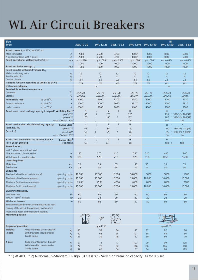
* 1) At 40 CO
* 2) N-Normal; S-Standard; H-High 3) Class “C” - Very high breaking capacity 4) for 0.5 sec
Rated current In at 55oC, at 50/60 Hz
Main conductor
N-conductor (only with 4 poles)
Rated operational voltage Ue at 50/60 Hz
Rated insulation voltage Ui
Rated impulse withstand voltage Uimp
Main conducting paths
Auxiliary circuits
Control circuits
Isolating function according to DIN EN 60 947-2
Utilization category
Permissible ambient temperature
Operation
Storage
Rated short circuit making capacity lcm (peak) kA
lcs (r.m.s) kA
Rated service short circuit breaking capacity,
(lcs = lcu)
Rated short time withstand current, lcw. KA
For 1 Sec at 50/60 Hz
Permissible load up to 55o C
for rear horizontal up to 60o C
main contacts up to 70o C
Power loss at In
with 3-phase symmetrical load
Fixed-mounted circuit-breaker
Withdrawable circuit-breaker
Operating times
Make-time
Break-time
Endurance
Switching frequency
690 V version
1000V version 3)
/1150V
Minimum interval
Between release by overcurrent release and next
closing of the circuit-breaker (only with autom
mechanical reset of the reclosing lockout)
Mounting position
Degree of protection
Weights Fixed-mounted circuit-breaker
3-pole Withdrawable circuit-breaker
Guide frame
4-pole Fixed-mounted circuit-breaker
Withdrawable circuit-breaker
Guide frame
A
A
AC V
AC V
kV
kV
kV
oCoC
Rating Class 2)
upto 500V
upto 690V3)
upto 1000V/1150V
Rating Class
Rating Class
2)
2)
upto 500V
upto 690V
upto 1000V/1150V3)
1 Sec Rating
A
A
A
W
W
ms
ms
1/h
1/h
ms
kg
kg
kg
kg
kg
kg
- / - / 50
55 / 66 / 80
- / - / 105
66 / 80 / 100
50 / 75 / 85
N / S / H
N / S / H
N / S / H
145 / 176 / 220
50 70
100 / 100
105 154
100 150(3P), 130(4P)
85 150(3P), 130(4P)
H C
/ /
/
/
/
/
/
/
H C
C H
220 330(3P), 286(4P)
187 330(3P), 286(4P) 105 / 165 / 187
2000 2500 3200 4000 5000 6300
2000 2500 3200 4000 5000 6300
up to 690/ up to 690/ up to 690/ up to 690/ up to 690/ up to 690/
1000 1000 1000 1000 1000 1000
1000 1000 1000 1000 1000 1000
12 12 12 12 12 12
4 4 4 4 4 4
2.5 2.5 2.5 2.5 2.5 2.5
yes yes yes yes yes yes
B B
-25/+70 -25/+70 -25/+70 -25/+70 -25/+70 -25/+70
-40/+70 -40/+70 -40/+70 -40/+70 -40/+70 -40/70
2000 2500 3200 4000 5000 5920
2000 2500 3070 4000 5000 5810
2000 2280 2870 4000 5000 5500
180 270 410 520 630 900
320 520 710 810 1050 1600
35 35 35 35 35 35
34 34 34 34 34 34
60 60 60 60 60 60
20 20 20 20 20 20
80 80 80 80 80 80
upto IP 55 upto IP 55
56 59 64 82 82 90
60 63 68 88 88 96
31 39 45 60 60 70
67 71 77 99 99 108
72 76 82 106 106 108
37 47 54 84 84 119
1)
0 030 30
NS
1-5
14
9
0 030 30
NS
1-5
15
0
NSE00927
h m
ax
= 1
mm
and/or
SizeType 3WL 12 20 3WL 12 25 3WL 12 32 3WL 13 40 3WL 13 50 3WL 13 63
II III
3)4000
40003)
up to 690/
1000
1000
12
4
2.5
yes
-25/+70
-40/+70
3950
3810
3600
750
925
35
34
60
20
80
85
121
52
103
146
62
3WL 1240
WL Air Circuit Breakers
13
Mechanical (without maintenance) operating cycles 10 000 10 000 10 000 5000 5000 500010 000
Mechanical (with maintenance) operating cycles 15 000 15 000 15 000 10 000 10 000 10 00015 000
Electrical (without maintenance) operating cycles 75 00 7500 4000 2000 2000 20004000
Electrical (with maintenance) operating cycles 15 000 15 000 15 000 10 000 10 000 10 00015 000
CMYK
CMYK
1
2
3
4
5
6
7
8
9
10
11
12
13
14
15
16
17
18
19
20
21
22
23
24
25
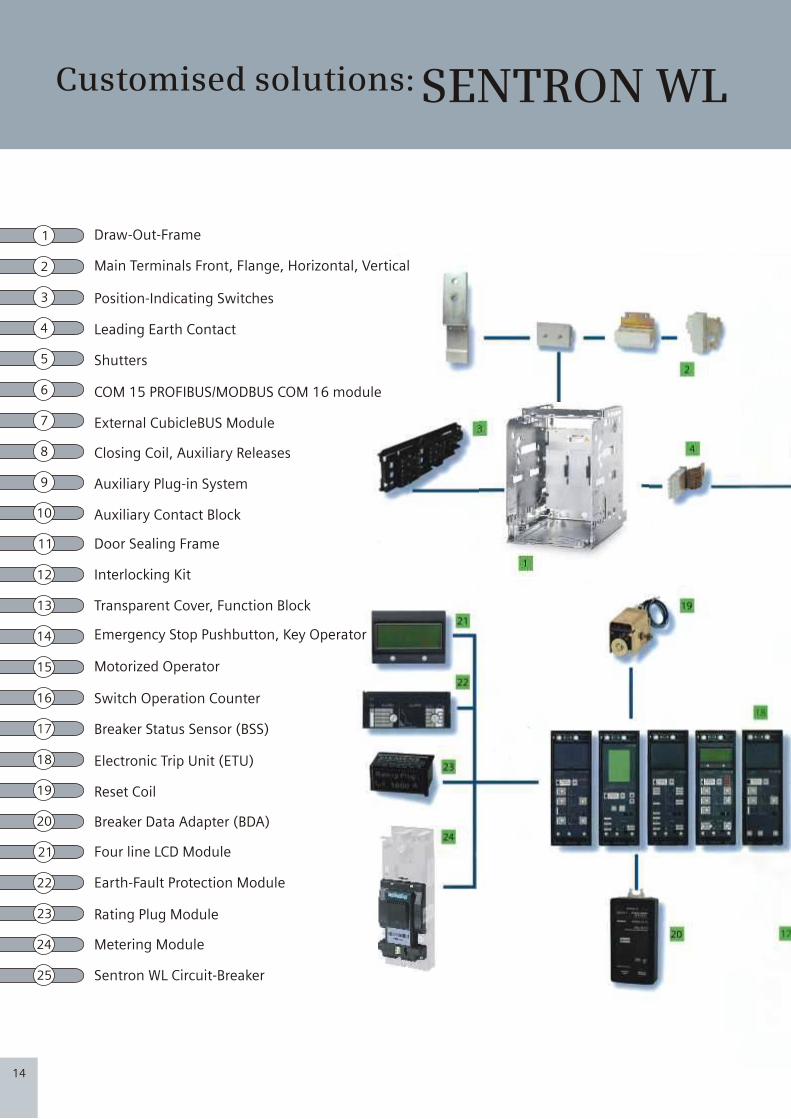
Draw-Out-Frame
Main Terminals Front, Flange, Horizontal, Vertical
Position-Indicating Switches
Leading Earth Contact
Shutters
COM 15 PROFIBUS/MODBUS COM 16 module
External CubicleBUS Module
Closing Coil, Auxiliary Releases
Auxiliary Plug-in System
Auxiliary Contact Block
Door Sealing Frame
Interlocking Kit
Transparent Cover, Function Block
Emergency Stop Pushbutton, Key Operator
Motorized Operator
Switch Operation Counter
Breaker Status Sensor (BSS)
Electronic Trip Unit (ETU)
Reset Coil
Breaker Data Adapter (BDA)
Four line LCD Module
Earth-Fault Protection Module
Rating Plug Module
Metering Module
Sentron WL Circuit-Breaker
Customised solutions: SENTRON WL
14
Rated current coding between circuit breaker and
guide frame
Option related coding
Withdrawable circuit breakers and guide frames are
equipped with a rated current coding as standard.
This ensures that in a guide frame only those circuit
breakers can be inserted whose contact strips match
the laminated contacts of the guide frame.
(see picture above)
Withdrawable circuit breakers and guide frames can
be retrofitted with an option related coding. This
permits the unique assignment of circuit breakers and
guide frames, taking into account different
equipment. If circuit breakers and guide frames do
not have the same coding. It is not possible to insert
the circuit breaker.
Circuit breakers and guide frames, taking into
account different equipment. If circuit breakers and
guide frames do not have the same coding. It is not
possible to insert the circuit breaker. There are 36
selectable coding options.
Rated current coding between circuit-breaker and guide frame
(1) Guide frame, inside left; inside right are the same
(2) Coding bolt on the guide rail in the guide frame
(3) Guide rail
(4) Withdrawable circuit-breaker right side; left side are the same
(5) Coding bolt on guide frame
(1)
NSE01032NS
E0
10
31
(2)
(3)
(4)
(5)
Interlocking of cubicle door
Access locking through the “mechanical ON” and
“OFF” button
Shutter
The cubicle door cannot be opened if the
- fixed-mounted circuit breaker is closed(transmission
of the locking signal by means of Bowden wire) or
- if the withdrawable circuit breaker is in connected
position.
The “mechanical ON” and “OFF” buttons are protected
by a cover that only permits actuation with a tool.
These caps are components of the interlocking set.
The cover strips of the shutter lock the laminated
contacts of the guide frame if the withdrawable circuit
breaker is withdrawn so that they fulfil the function of
a touch guard.
The cover strips can be manually opened with the strip
lifter.
The cover strips can be fixed in different positions with
padlocks and protected from unauthorized
manipulation.
Additional equipment for guide frames
19

CMYK
CMYK
SENTRON WL: superior individual products, integrated into comprehensive power distribution system-to the extent of providing solutions specific to particular industrial sector and infrastructure projects
with optional accessories
15
Locking Device
Locking device in OFF position
Locking device for “electrical ON”
Locking device for “mechanical ON”
“Safe OFF” switch independent locking device
against unauthorized closing.
Locking device for crank handle
This function prevents the circuit breaker being
closed and fulfils the main switch-characteristics
according to EN 60 204 (VDE 0113)- line
disconnector. This locking only affects this circuit
breaker.
After a circuit breaker is replaced, it is no longer
possible to prevent it being closed unless the new
circuit breaker is also protected against
unauthorized closing.
To activate the locking device, the circuit breaker
must be open. If the circuit breaker is closed, the
locking device is blocked. The blocking is only
effective if the key is withdrawn. The safety key can
only be withdrawn in the “OFF” position.
Prevents unauthorized electrical closing at the front
panel. Mechanical and remote closing are still
possible. The blocking is only effective if the key is
withdrawn.
Prevents unauthorized mechanical closing. The
mechanical ON button can only be actuated if the
key is inserted (key operation). Closing through the
“electrical ON” or remote closing are still possible.
The blocking is only effective if the key is
withdrawn.
This special function for withdrawable circuit
breakers prevents closing, independent of circuit
breaker, and fulfils the main switch-characteristics
according to EN 60 204 (VDE 0113)- line
disconnector. Unauthorized closing is also not
possible after replacement of a circuit breaker.
To activate the locking, the circuit breaker must be
switched off. If the circuit breaker is switched on,
the locking device is blocked. The blocking is only
effective if the key is withdrawn. The safety key can
only be withdrawn in the “OFF” position.
Prevents withdrawal of the crank handle. The
circuit breaker is protected against moving. The
blocking is only effective if the key is withdrawn.
Locking device for mechanical “OFF”
Locking device for charging lever
Locking device against resetting the trip indicator
Sealing cap over “electrical ON” button
Sealing cap over “mechanical ON” and “OFF”
button
Sealing device for overcurrent release
Closing lockout with open cubicle door
Locking device against moving if the cubicle door
is open for withdrawable circuit-breakers
Prevents unauthorized mechanical disconnection at
the front panel. The mechanical OFF” button can
only be actuated if the key is inserted (key
operation). Remote disconnection is still possible.
The blocking is only effective if the key is withdrawn.
The charging lever can be locked with a padlock
making it impossible to manually charge the stored
energy mechanism.
A lockable cover prevents the manual resetting of
the trip indicator after an overcurrent release. This
locking device is delivered together with the option
tranparent cover for overcurrent release.
The “electrical ON button” is fitted with a sealing cap
as standard.
The interlocking set includes blanking caps that can
be sealed.
The transparent cover can be sealed. The areas of
the parameter setting are covered against
unauthorized access. Openings enable access to the
query and test button.
The readiness to close is mechanically deactivated if
the cubicle door is open. The circuit breaker cannot
be closed either mechanically or electrically.
Transmission of the locking signal by means of the
Bowden wire.
The crank handle is blocked if the cubicle door is
open and cannot be withdrawn. It is not possible to
move withdrawable circuit breakers. The blocking is
only effective if the crank handle is inserted.
Sealing devices
18

CMYK
CMYK
1) Arc chute cover (optional)
2) Arcing openings
3) Opening for crane hooks
4) Shutter (optional)
5) Locking device (shutter) (optional)
6) Type label for guide frame
7) Disconnecting contact
8) Earthing terminal O14 mm
9) Locking device travel rail
10) Locking device against moving if the cubicle door is open (optional)
11) Door interlock for guide frame (optional)
12) Guide rail
13) Ampere rating coding by factory
14) Sliding contact for circuit-breaker earthing (optional)
15) Option related coding
16) Shutter operating device (optional)
17) Position signal switch (optonal)
18) Sliding contact module for auxiliary conductor (quantity is equipment-dependent)
1) Arc chute
2) Handle
3) ID label
4) Motor switch (optional) or “electrical ON” (optional)
5) Type label of circuit-breaker
6) Spring charge indicator
7) “Mechanical ON” button
8) Rated current data
9) Insertion pologramm
10) Operating cycle counter (optional)
11) Charging lever
12) Crank handle
13) Transport shalt for withdrawable unit
14) Equipment label
15) Earth terminal
16) Position indicator
17) Earth fault protection table
18) Crank handle safety lock
19) “Mechanical OFF” button or “emergency OFF” mushroom push button (optional)
20) Ready-to-close indicator
21) Contact position indicator
22) Trip indicator (reset button)
23) Locking device “Safe OFF” (optional)
24) Front panel
25) Terminal strip for auxiliary contacts
3 and 4 pole, up to 6300A- fixed mounted and withdrawable version
DescriptionGUIDE FRAME
(1)
(2)
(3)
(4)
(5)
(6)
(7)
(8)
(9)
(10)
(11)
(12)
(13)
(14)
(15)
(16)
(17)
(18)
DescriptionCIRCUIT-BREAKERS
(1)
(2)
(3)
(4)
(5)
(6)
(7)
(8)
(9)
(10)(11)
(12)
(13)
(14)
(15)
(16)
(17)
(18)
(19)
(20)
(21)
(22)
(23)
(24)
(25)
(26)
(27)
(28)
16
Operating cycle counter
Resetting the manual trip signal
Automatic reset of the reclosing lockout
Trip signal switch
Ready-to-close signal contact
A 5-digit operating cycle counter is available with the
motorized operating mechanism. The display is
incremented by “1” as soon as the stored energy
mechanism is fully charged.
If the circuit breaker has been tripped, this is indicated
by the protruding red reset button on the ETU.
Actuation of the reset button resets the trip solenoid
and the trip signal. If this manual indicator is to be
remotely reset, the option is available to equip the
reset button with a reset solenoid. With this option,
the circuit breaker can be reset both manually and
electrically.
If the ETU is released the circuit breaker cannot be
reclosed until the release has been either electrically or
manually reset with the option “automatic reset of the
reclosing lockout”, the circuit breaker is ready-to-close
immediately after a release. The reset of the manual
trip indicator is not contained in this option.
If the circuit breaker is tripped through overload, short-
circuit or earth fault, this can be indicated by the trip
signal switch. This signal switch is available as an
optional extra. If the circuit breaker is communication
capable, this option is available as standard.
The SENTRON WL circuit breakers are equipped with a
visual ready-to-close facility as standard. The option to
transmit this readiness to close over a signal contact is
also available. If the circuit breaker is operated through
communication, this signal switch is fitted as standard.
Up to two auxiliary releases can be installed at the
same time. The following are available:1 shunt release or 1 undervoltage release or 2 shunt
releases or 1 shunt release + 1 undervoltage release.
The shunt release instantly turns off the circuit-breaker
when the working voltage is applied. The shunt
release “F1” is available in two versions; 5% duty ratio
for over excitation and 100% duty ratio for permanent-
magnet excitation. This can be used as lock-out against
startup.An energy storage device for the shunt release allows
the circuit breaker to be turned off after a control
voltage failure.
The undervoltage release turns off the circuit breaker
when the working voltage falls below a specific value
or is not applied. The circuit breaker cannot be
switched ON manually or by means of an electrical ON
command if the undervoltage release is not given the
rated voltage. The under voltage release “Y1” is
without time lag as standard and the customer can
switch between t1 < 80ms and t1 < 200ms.A further version is available : undervoltage release
with 0.2 to 3.2 s lag.
One signal contact per auxiliary release is available to
interrogate the switching positions of the auxiliary
release.
Serves to electrically close the circuit breaker by means
of a local or remote electrical “ON” button.
For automatic charging of the stored energy
mechanism. Is switched on when the stored energy
mechanism is released and the control voltage is
available. Automatically switch off after charging.
Manual actuation of the storage can function
independently.
The interlocking set is required when the operability of
the mechanical ON and OFF buttons need to be
adapted to special demands of the switchgear
operation by retrofitting various accessories (e.g.
Safety locks, access lock-outs preventing tool
operation, seals.)
Knob-operated switch for turning off the motorized
operating mechanism.
Shunt release
Undervoltage release
Signal contact for auxiliary release
Closing solenoid
Interlocking set
Motor switch
Motorized operating mechanism
Display message and control elements.
DescriptionAuxiliary release
17

CMYK
CMYK
1) Arc chute cover (optional)
2) Arcing openings
3) Opening for crane hooks
4) Shutter (optional)
5) Locking device (shutter) (optional)
6) Type label for guide frame
7) Disconnecting contact
8) Earthing terminal O14 mm
9) Locking device travel rail
10) Locking device against moving if the cubicle door is open (optional)
11) Door interlock for guide frame (optional)
12) Guide rail
13) Ampere rating coding by factory
14) Sliding contact for circuit-breaker earthing (optional)
15) Option related coding
16) Shutter operating device (optional)
17) Position signal switch (optonal)
18) Sliding contact module for auxiliary conductor (quantity is equipment-dependent)
1) Arc chute
2) Handle
3) ID label
4) Motor switch (optional) or “electrical ON” (optional)
5) Type label of circuit-breaker
6) Spring charge indicator
7) “Mechanical ON” button
8) Rated current data
9) Insertion pologramm
10) Operating cycle counter (optional)
11) Charging lever
12) Crank handle
13) Transport shalt for withdrawable unit
14) Equipment label
15) Earth terminal
16) Position indicator
17) Earth fault protection table
18) Crank handle safety lock
19) “Mechanical OFF” button or “emergency OFF” mushroom push button (optional)
20) Ready-to-close indicator
21) Contact position indicator
22) Trip indicator (reset button)
23) Locking device “Safe OFF” (optional)
24) Front panel
25) Terminal strip for auxiliary contacts
3 and 4 pole, up to 6300A- fixed mounted and withdrawable version
DescriptionGUIDE FRAME
(1)
(2)
(3)
(4)
(5)
(6)
(7)
(8)
(9)
(10)
(11)
(12)
(13)
(14)
(15)
(16)
(17)
(18)
DescriptionCIRCUIT-BREAKERS
(1)
(2)
(3)
(4)
(5)
(6)
(7)
(8)
(9)
(10)(11)
(12)
(13)
(14)
(15)
(16)
(17)
(18)
(19)
(20)
(21)
(22)
(23)
(24)
(25)
(26)
(27)
(28)
16
Operating cycle counter
Resetting the manual trip signal
Automatic reset of the reclosing lockout
Trip signal switch
Ready-to-close signal contact
A 5-digit operating cycle counter is available with the
motorized operating mechanism. The display is
incremented by “1” as soon as the stored energy
mechanism is fully charged.
If the circuit breaker has been tripped, this is indicated
by the protruding red reset button on the ETU.
Actuation of the reset button resets the trip solenoid
and the trip signal. If this manual indicator is to be
remotely reset, the option is available to equip the
reset button with a reset solenoid. With this option,
the circuit breaker can be reset both manually and
electrically.
If the ETU is released the circuit breaker cannot be
reclosed until the release has been either electrically or
manually reset with the option “automatic reset of the
reclosing lockout”, the circuit breaker is ready-to-close
immediately after a release. The reset of the manual
trip indicator is not contained in this option.
If the circuit breaker is tripped through overload, short-
circuit or earth fault, this can be indicated by the trip
signal switch. This signal switch is available as an
optional extra. If the circuit breaker is communication
capable, this option is available as standard.
The SENTRON WL circuit breakers are equipped with a
visual ready-to-close facility as standard. The option to
transmit this readiness to close over a signal contact is
also available. If the circuit breaker is operated through
communication, this signal switch is fitted as standard.
Up to two auxiliary releases can be installed at the
same time. The following are available:1 shunt release or 1 undervoltage release or 2 shunt
releases or 1 shunt release + 1 undervoltage release.
The shunt release instantly turns off the circuit-breaker
when the working voltage is applied. The shunt
release “F1” is available in two versions; 5% duty ratio
for over excitation and 100% duty ratio for permanent-
magnet excitation. This can be used as lock-out against
startup.An energy storage device for the shunt release allows
the circuit breaker to be turned off after a control
voltage failure.
The undervoltage release turns off the circuit breaker
when the working voltage falls below a specific value
or is not applied. The circuit breaker cannot be
switched ON manually or by means of an electrical ON
command if the undervoltage release is not given the
rated voltage. The under voltage release “Y1” is
without time lag as standard and the customer can
switch between t1 < 80ms and t1 < 200ms.A further version is available : undervoltage release
with 0.2 to 3.2 s lag.
One signal contact per auxiliary release is available to
interrogate the switching positions of the auxiliary
release.
Serves to electrically close the circuit breaker by means
of a local or remote electrical “ON” button.
For automatic charging of the stored energy
mechanism. Is switched on when the stored energy
mechanism is released and the control voltage is
available. Automatically switch off after charging.
Manual actuation of the storage can function
independently.
The interlocking set is required when the operability of
the mechanical ON and OFF buttons need to be
adapted to special demands of the switchgear
operation by retrofitting various accessories (e.g.
Safety locks, access lock-outs preventing tool
operation, seals.)
Knob-operated switch for turning off the motorized
operating mechanism.
Shunt release
Undervoltage release
Signal contact for auxiliary release
Closing solenoid
Interlocking set
Motor switch
Motorized operating mechanism
Display message and control elements.
DescriptionAuxiliary release
17
CMYK
CMYK
SENTRON WL: superior individual products, integrated into comprehensive power distribution system-to the extent of providing solutions specific to particular industrial sector and infrastructure projects
with optional accessories
15
Locking Device
Locking device in OFF position
Locking device for “electrical ON”
Locking device for “mechanical ON”
“Safe OFF” switch independent locking device
against unauthorized closing.
Locking device for crank handle
This function prevents the circuit breaker being
closed and fulfils the main switch-characteristics
according to EN 60 204 (VDE 0113)- line
disconnector. This locking only affects this circuit
breaker.
After a circuit breaker is replaced, it is no longer
possible to prevent it being closed unless the new
circuit breaker is also protected against
unauthorized closing.
To activate the locking device, the circuit breaker
must be open. If the circuit breaker is closed, the
locking device is blocked. The blocking is only
effective if the key is withdrawn. The safety key can
only be withdrawn in the “OFF” position.
Prevents unauthorized electrical closing at the front
panel. Mechanical and remote closing are still
possible. The blocking is only effective if the key is
withdrawn.
Prevents unauthorized mechanical closing. The
mechanical ON button can only be actuated if the
key is inserted (key operation). Closing through the
“electrical ON” or remote closing are still possible.
The blocking is only effective if the key is
withdrawn.
This special function for withdrawable circuit
breakers prevents closing, independent of circuit
breaker, and fulfils the main switch-characteristics
according to EN 60 204 (VDE 0113)- line
disconnector. Unauthorized closing is also not
possible after replacement of a circuit breaker.
To activate the locking, the circuit breaker must be
switched off. If the circuit breaker is switched on,
the locking device is blocked. The blocking is only
effective if the key is withdrawn. The safety key can
only be withdrawn in the “OFF” position.
Prevents withdrawal of the crank handle. The
circuit breaker is protected against moving. The
blocking is only effective if the key is withdrawn.
Locking device for mechanical “OFF”
Locking device for charging lever
Locking device against resetting the trip indicator
Sealing cap over “electrical ON” button
Sealing cap over “mechanical ON” and “OFF”
button
Sealing device for overcurrent release
Closing lockout with open cubicle door
Locking device against moving if the cubicle door
is open for withdrawable circuit-breakers
Prevents unauthorized mechanical disconnection at
the front panel. The mechanical OFF” button can
only be actuated if the key is inserted (key
operation). Remote disconnection is still possible.
The blocking is only effective if the key is withdrawn.
The charging lever can be locked with a padlock
making it impossible to manually charge the stored
energy mechanism.
A lockable cover prevents the manual resetting of
the trip indicator after an overcurrent release. This
locking device is delivered together with the option
tranparent cover for overcurrent release.
The “electrical ON button” is fitted with a sealing cap
as standard.
The interlocking set includes blanking caps that can
be sealed.
The transparent cover can be sealed. The areas of
the parameter setting are covered against
unauthorized access. Openings enable access to the
query and test button.
The readiness to close is mechanically deactivated if
the cubicle door is open. The circuit breaker cannot
be closed either mechanically or electrically.
Transmission of the locking signal by means of the
Bowden wire.
The crank handle is blocked if the cubicle door is
open and cannot be withdrawn. It is not possible to
move withdrawable circuit breakers. The blocking is
only effective if the crank handle is inserted.
Sealing devices
18
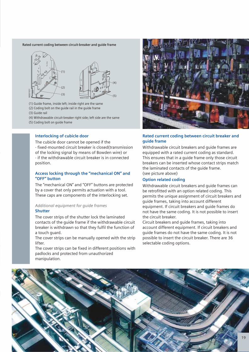
CMYK
CMYK
1
2
3
4
5
6
7
8
9
10
11
12
13
14
15
16
17
18
19
20
21
22
23
24
25
Draw-Out-Frame
Main Terminals Front, Flange, Horizontal, Vertical
Position-Indicating Switches
Leading Earth Contact
Shutters
COM 15 PROFIBUS/MODBUS COM 16 module
External CubicleBUS Module
Closing Coil, Auxiliary Releases
Auxiliary Plug-in System
Auxiliary Contact Block
Door Sealing Frame
Interlocking Kit
Transparent Cover, Function Block
Emergency Stop Pushbutton, Key Operator
Motorized Operator
Switch Operation Counter
Breaker Status Sensor (BSS)
Electronic Trip Unit (ETU)
Reset Coil
Breaker Data Adapter (BDA)
Four line LCD Module
Earth-Fault Protection Module
Rating Plug Module
Metering Module
Sentron WL Circuit-Breaker
Customised solutions: SENTRON WL
14
Rated current coding between circuit breaker and
guide frame
Option related coding
Withdrawable circuit breakers and guide frames are
equipped with a rated current coding as standard.
This ensures that in a guide frame only those circuit
breakers can be inserted whose contact strips match
the laminated contacts of the guide frame.
(see picture above)
Withdrawable circuit breakers and guide frames can
be retrofitted with an option related coding. This
permits the unique assignment of circuit breakers and
guide frames, taking into account different
equipment. If circuit breakers and guide frames do
not have the same coding. It is not possible to insert
the circuit breaker.
Circuit breakers and guide frames, taking into
account different equipment. If circuit breakers and
guide frames do not have the same coding. It is not
possible to insert the circuit breaker. There are 36
selectable coding options.
Rated current coding between circuit-breaker and guide frame
(1) Guide frame, inside left; inside right are the same
(2) Coding bolt on the guide rail in the guide frame
(3) Guide rail
(4) Withdrawable circuit-breaker right side; left side are the same
(5) Coding bolt on guide frame
(1)
NSE01032NS
E0
10
31
(2)
(3)
(4)
(5)
Interlocking of cubicle door
Access locking through the “mechanical ON” and
“OFF” button
Shutter
The cubicle door cannot be opened if the
- fixed-mounted circuit breaker is closed(transmission
of the locking signal by means of Bowden wire) or
- if the withdrawable circuit breaker is in connected
position.
The “mechanical ON” and “OFF” buttons are protected
by a cover that only permits actuation with a tool.
These caps are components of the interlocking set.
The cover strips of the shutter lock the laminated
contacts of the guide frame if the withdrawable circuit
breaker is withdrawn so that they fulfil the function of
a touch guard.
The cover strips can be manually opened with the strip
lifter.
The cover strips can be fixed in different positions with
padlocks and protected from unauthorized
manipulation.
Additional equipment for guide frames
19

CMYK
CMYK
Position signal contact for guide frame
Mutual mechanical circuit breaker
interlocking
Phase barriers
Position signal contacts can be retrofitted
to the guide frame. These can be used to
analyze the position of the circuit breaker
in the guide frame.
The module for mutual mechanical
interlocking can be implemented for two
or three SENTRON WL circuit breakers and
is simple to adapt to the respective
version. Fixed mounted and withdrawable
circuit breakers are compatible and can be
implemented together in a single system.
This is also possible with circuit breakers
3WT.
The circuit breakers can be installed either
next to one another or on top of one
another, whereby the distance between
the circuit breakers is determined only by
the length of the Bowden wire.
The Bowden wire are available upto a
length of 6m. Lockout signal are
forwarded over the Bowden wires with
withdrawable circuit breakers the
interlocking is only effective in connected
position. The mechanical service life of
Bowden wires is 10000 operating cycles.
For the mutual mechanical interlocking of
circuit breakers also see the adjacent
table.
Plant manufacturers can make phase
barriers out of insulation material as a
protection against internal arcs
Guiding grooves are provided at the rear
of the fixed-mounted circuit breaker or
guide frame.
Interlockingof two mutualcircuit breakers
Interlockingof three non- mutualcircuit breakers
Interlockingof three mutualcircuit breakers
Interlocking of threecircuit breakers, twoof which are mutual
Mutual mechanical interlocking of circuit breaker - examples
S1S1
S1
S1 S1
S3
S3
S3S3
GG G
S2
S2
S2
S2
S2
NSE01041 NSE01044 NSE01045NSE01043NSE01042
Arc chute cover
The arc chute cover is available as an optional features for the guide frame.
It serves to protect switchgear parts that are located directly next to the
circuit breaker.
20
Position of the withdrawable circuit breaker in the guide frame
(2) Main circuit
(1) Auxiliary circuit
(3) Cubicle door
(4) Shutter
Connectedposition
Test position
Disconnected position
Maintenance position
Representation Position indicator
Discon-nected
Discon-nected
Connected
ConnectedConnected
Discon-nected
Discon-nected
Discon-nected
Closed
ClosedClosed
Closed
Closed
Closed
Open
Open
Main circuit Auxiliarycircuit
Cubicledoor
Shutter
CONNECT
CONNECT
CONNECT
CONNECT
TEST
TEST
TEST
TEST
DISCONN
DISCONN
DISCONN
DISCONN
(2)
NSE01033
NSE01034
NSE01035
NSE01036
NSE01037
NSE01038
NSE01039
NSE01040
(1)
(3)
(4)
* 1) At 40 CO
* 2) N-Normal; S-Standard; H-High 3) Class “C” - Very high breaking capacity 4) for 0.5 sec
Rated current In at 55oC, at 50/60 Hz
Main conductor
N-conductor (only with 4 poles)
Rated operational voltage Ue at 50/60 Hz
Rated insulation voltage Ui
Rated impulse withstand voltage Uimp
Main conducting paths
Auxiliary circuits
Control circuits
Isolating function according to DIN EN 60 947-2
Utilization category
Permissible ambient temperature
Operation
Storage
Rated short circuit making capacity lcm (peak) kA
lcs (r.m.s) kA
Rated service short circuit breaking capacity,
(lcs = lcu)
Rated short time withstand current, lcw. KA
For 1 Sec at 50/60 Hz
Permissible load up to 55o C
for rear horizontal up to 60o C
main contacts up to 70o C
Power loss at In
with 3-phase symmetrical load
Fixed-mounted circuit-breaker
Withdrawable circuit-breaker
Operating times
Make-time
Break-time
Endurance
Switching frequency
690 V version
1000V version 3)
/1150V
Minimum interval
Between release by overcurrent release and next
closing of the circuit-breaker (only with autom
mechanical reset of the reclosing lockout)
Mounting position
Degree of protection
Weights Fixed-mounted circuit-breaker
3-pole Withdrawable circuit-breaker
Guide frame
4-pole Fixed-mounted circuit-breaker
Withdrawable circuit-breaker
Guide frame
A
A
AC V
AC V
kV
kV
kV
oCoC
Rating Class 2)
upto 500V
upto 690V3)
upto 1000V/1150V
Rating Class
Rating Class
2)
2)
upto 500V
upto 690V
upto 1000V/1150V3)
1 Sec Rating
A
A
A
W
W
ms
ms
1/h
1/h
ms
kg
kg
kg
kg
kg
kg
- / - / 50
55 / 66 / 80
- / - / 105
66 / 80 / 100
50 / 75 / 85
N / S / H
N / S / H
N / S / H
145 / 176 / 220
50 70
100 / 100
105 154
100 150(3P), 130(4P)
85 150(3P), 130(4P)
H C
/ /
/
/
/
/
/
/
H C
C H
220 330(3P), 286(4P)
187 330(3P), 286(4P) 105 / 165 / 187
2000 2500 3200 4000 5000 6300
2000 2500 3200 4000 5000 6300
up to 690/ up to 690/ up to 690/ up to 690/ up to 690/ up to 690/
1000 1000 1000 1000 1000 1000
1000 1000 1000 1000 1000 1000
12 12 12 12 12 12
4 4 4 4 4 4
2.5 2.5 2.5 2.5 2.5 2.5
yes yes yes yes yes yes
B B
-25/+70 -25/+70 -25/+70 -25/+70 -25/+70 -25/+70
-40/+70 -40/+70 -40/+70 -40/+70 -40/+70 -40/70
2000 2500 3200 4000 5000 5920
2000 2500 3070 4000 5000 5810
2000 2280 2870 4000 5000 5500
180 270 410 520 630 900
320 520 710 810 1050 1600
35 35 35 35 35 35
34 34 34 34 34 34
60 60 60 60 60 60
20 20 20 20 20 20
80 80 80 80 80 80
upto IP 55 upto IP 55
56 59 64 82 82 90
60 63 68 88 88 96
31 39 45 60 60 70
67 71 77 99 99 108
72 76 82 106 106 108
37 47 54 84 84 119
1)
0 030 30
NS
1-5
14
9
0 030 30
NS
1-5
15
0
NSE00927
h m
ax
= 1
mm
and/or
SizeType 3WL 12 20 3WL 12 25 3WL 12 32 3WL 13 40 3WL 13 50 3WL 13 63
II III
3)4000
40003)
up to 690/
1000
1000
12
4
2.5
yes
-25/+70
-40/+70
3950
3810
3600
750
925
35
34
60
20
80
85
121
52
103
146
62
3WL 1240
WL Air Circuit Breakers
13
Mechanical (without maintenance) operating cycles 10 000 10 000 10 000 5000 5000 500010 000
Mechanical (with maintenance) operating cycles 15 000 15 000 15 000 10 000 10 000 10 00015 000
Electrical (without maintenance) operating cycles 75 00 7500 4000 2000 2000 20004000
Electrical (with maintenance) operating cycles 15 000 15 000 15 000 10 000 10 000 10 00015 000
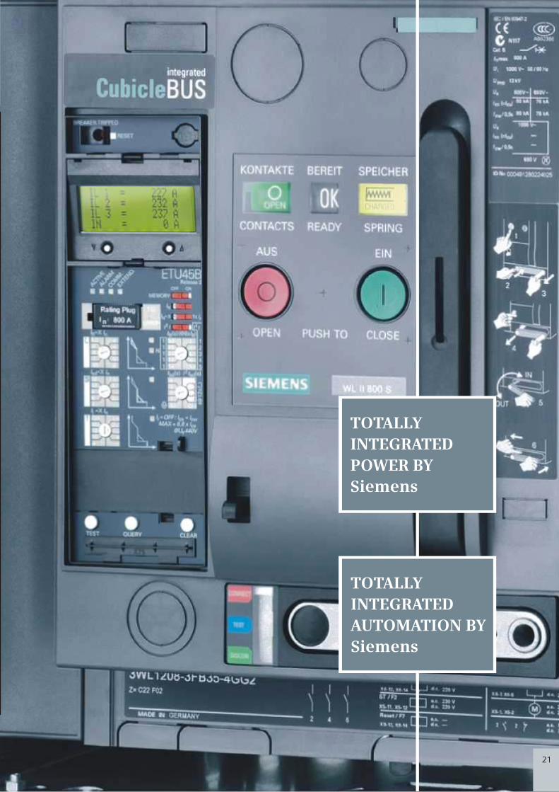
CMYK
CMYK
TOTALLY
INTEGRATED
POWER BY
Siemens
TOTALLY
INTEGRATED
AUTOMATION BY
Siemens
21
SENTRON WL: An air circuitbreaker family for the complete spectrum of power distribution whether in building infrastructure or industrial applications.
Rated current In at 55oC, at 50/60 Hz
Main conductor A up to 1000 1250 1600 800 1000 1250
N-conductor (only with 4 poles) A up to 1000 1250 1600 800 1000 1250
Rated operational voltage Ue at 50/60 Hz AC V up to 690 up to 690 up to 690 up to 690/ up to 690/ up to 690/
1000 1000 1000
Rated insulation voltage Ui AC V 1000 1000 1000 1000 1000 1000
Rated impulse withstand voltage Uimp
Main conducting paths kV 12 12 12 12 12 12
Auxiliary circuits kV 4 4 4 4 4 4
Control circuits kV 2.5 2.5 2.5 2.5 2.5 2.5
Isolating function according to DIN EN 60 947-2 yes yes yes yes yes yes
Utilization category
Permissible ambient temperature
Operation oC -25/+70 -25/+70 -25/+70 -25/+70 -25/+70 -25/+70
Storage oC -40/+70 -40/+70 -40/+70 -40/+70 -40/70 -40/+70
Rated short circuit making capacity lcm (peak) kA Rating Class 2)
upto 500V
upto 690V
upto 1000V/1150V
lcs (r.m.s) kA
Rated service short circuit breaking capacity, Rating Class 2)
3)
3)
(lcs = lcu) upto 500V
upto 690V
upto 1000V/1150V
Rated short time withstand current, lcw. kA
For 1 Sec at 50/60 Hz 1 Sec Rating
Permissible load up to 55o
C A 1000 1250 1600 800 1000 1250
for rear horizontal up to 60o
C A 1000 1250 1600 800 1000
1000
1250
main contacts up to 70o
C A 1000 1210 1490 800 1250
Power loss at In
with 3-phase symmetrical load
Fixed-mounted circuit-breaker W 100 105 150 40 45 80
Withdrawable circuit-breaker W 195 205 350 85 95 165
Operating times
Make-time ms 35 35 35 35 35 35
Break-time
Switching frequency
690 V version 1/h 60 60 60 60 60 60
1000V version 3)
/1150V 1/h - - - 20 20 20
Minimum interval ms 80 80
and/or
80 80 80 80
Between release by overcurrent release and next
closing of the circuit-breaker (only with autom
mechanical reset of the reclosing lockout)
Mounting position
Degree of protection
Weights Fixed-mounted circuit-breaker kg 43 43 43 56 56 56
3-pole Withdrawable circuit-breaker kg 45 45 45 60 60 60
Guide frame kg 25 25 25 31 31 31
4-pole Fixed-mounted circuit-breaker kg 50 50 50 67 67 67
Withdrawable circuit-breaker kg 54 54 54 72 72 72
Guide frame kg 30 30 30 37 37 37
- / 50
66 / 80
- / 105
80 / 100
75 / 85
S / H
S / H
S / H
176 / 220
165 / 187
4) 50 / 50
55 / 66
42 / 50
/
B B
N / S
N / S
N / S
121 / 145
88 / 105
- / -
Size
Type up to3WL 11 12 3WL 11 16 3WL 12 08 3WL 12 10 3WL 12 12
3WL11 10
III
1600
1600
up to 690/
1000
1000
12
4
2.5
yes
-25/+70
-40/+70
1600
1600
1600
85
175
35
60
20
80
56
60
31
67
72
37
3WL 12 16
0 030 30
NS
1-5
14
9
0 030 30
NS
1-5
15
0
NSE00927
h m
ax
= 1
mm
upto IP 55 upto IP 55
Rating Class 2)
Technical Overview : SENTRON
12
Mechanical (without maintenance) operating cycles 10 000 10 000 10 000 10 000 10 000 10 000 10 000
Mechanical (with maintenance) operating cycles 20 000 20 000 20 000 15 000 15 000 15 000 15 000
Electrical (without maintenance) operating cycles 10 000 10 000 10 000 75 00 75 00 75 00 75 00
Electrical (with maintenance) operating cycles 20 000 20 000 20 000 15 000 15 000 15 000 15 000
ms 38 38 38 34 34 34
Endurance
34

CMYK
CMYK
Easy to Plan
Perfectly Modular
Circuit-breakers from
100A to 6300A
Simple planning with
SIMARIS design
Cost Saving
Simple, rapid retrofitting
Reduced parts variance
ONo derating till 55 C
High power rating - low
space requirement
11
SENTRON 3VL Circuit Breaker
Microprocessor based release with LCD
Microprocessor based release
COM10 PROFIBUS /COM11 MODBUS module with. ZSI
COM20 PROFIBUS /COM21 MODBUS module with. ZSI
Breaker Data Adapter (BDA)
BDA Plus with Ethernet Interface
Browser-capable input & output (e.g notebook)
SENTRON 3WL Circuit Breaker
COM 15 PROFIBUS / COM 16 MODBUS Module
Breaker Status Sensor (BSS)1) For a MODBUS connection the COM16 module is required
2) For a MODBUS connection the COM21 module is required
releaseMicroprocessor based
Metering function Plus
ZSI (Zone-Selective Interlocking) module
Digital output module as relay contacts
Digital output module as relay contacts, configurable
Analog output module
Digital input module
Switch ES Power on PC
PLC e.g. SIMATIC S7
Power Management System
Communication capable SENTRON Power Monitoring Devices
1
2
3
4
5
6
7
8
9
10
11
12
13
14
15
16
17
18
19
20
21
22
Technological leaders
amongst the Circuit breakers:
22
System Solutions
State-of-the-art
communication
Diagnosis also possible
via the Internet
Power Management

CMYK
CMYK
SENTRON WL circuit-breakers with I = 1000 A and ETU 45B or ETU 55B
electronic release
Inverse-time delayed overload range L
.01
.1
1
10
100
100 1000 10000 100000
1000
10000
t [s
]
I [A]
SENTRON WL circuit-breakers with I = 1000 A and ETU 45B or ETU 55B
electronic release
Instantaneous short-circuit range l
.01
.1
1
10
100
100 1000 10000 100000
1000
10000
t [s
]
I [A]
SENTRON WL circuit-breakers with I = 1000 A and ETU 45B or ETU 55B
electronic release
Short-time delayshort-circuit range S l
.01
.1
1
10
100
100 1000 10000 100000
1000
10000
t [s
]
I [A]
SENTRON WL circuit-breakers with I = 1000 A and ETU 45B or ETU 55B
electronic release
Earth-fault protection range G
.01
.1
1
10
100
100 1000 10000 100000
1000
10000
t [s
]
I [A]
Tripping characteristics
Every release type and every setting has its
own characteristic. You will find just a small
selection of these illustrated below. The
characteristics show the respective greatest
and smallest setting range of SENTRON WL
circuit-breakers with 1000A rated current,
690V rated voltage with various releases.
The characteristics show the behavior of the
overcurrent release when it is activated by a
current already flowing before the release.
If the overcurrent release is not activated, the
opening time is prolonged up to 15ms,
depending on the value of the
overcurrent. To determine the total
break-times of the circuit-breakers about
15ms must be added to the displayed
opening times for the arc duration.
The displayed characteristics apply for
ambient temperature at the circuit-
breaker of -5 to +55 Deg C. The release
can be operated at ambient
temperatures of -20 to +70 Deg C.
2Inverse-time delayed overload range L I t=constant
2 4Overlapping of the Inverse-time delayed overload range L I t and I t
4Inverse-time delayed overload range L I = constant
Short-time delayed short-circuit range S
Instantaneous short-circuit range I
Earth-fault protection range G
You will find further characteristics in the manual or in the SIMARIS deSign planning and configuring tool Or if you have any further queries, please contact your partner.
10
SENTRON Communication Solution
23

CMYK
CMYK
Application:
Properties:
The multitalent with graphical display for network analysis “CubicleBUS integrated”.
As for ETU45B plus the following:
1. Two protective parameter steps that can be stored seperately in the release (switch-selectable through external signal).
2. Overload protection that can be switched off for use with modern operating mechanism.
3. Adjustable lag of the delayed short-circuit protection up to 4000ms.
4. Neutral conductor protection adjustable to I = 2 In n .
5. Setting of protective functions by means of control keys or Breaker Data Adapter or through communication interface.
6. Graphical display of all parameters and event/curve characteristics.
7. Storage of events and causes of release for specific error analysis.
8. High-contrast background - lit graphical display with sleep mode.
Available not available optional
Ra
ng
es
/ F
un
ctio
ns
Ov
erl
oa
d p
rote
ctio
n
Sh
ort
-tim
e d
ela
ye
dsh
ort
-cir
cuit
pro
tect
ion
Inst
an
tan
eo
us
sho
rt-
circ
uit
pro
tect
ion
Pro
tect
ion
of
ne
utr
al co
nd
uct
or
Ea
rth
-fa
ult
p
rote
ctio
n
ZS
I (z
on
e-s
ele
ctiv
ein
terl
ock
ing
)
LCD
4 l
ine
s
LCD
gra
ph
ic
Co
mm
un
ica
tio
n v
iaP
rofi
bu
s D
P/M
OD
BU
S
Me
teri
ng
fu
nct
ion
s
Se
lect
ab
lep
ara
me
ter
sets
Fre
ely
pro
gra
mm
ab
lep
ara
me
ters
ETU 76B
ETU 45B
ETU 27B
ETU 25B
ETU 15B
9
The Cubicle BUS is the internal bus system, providing the interconnection between
all the intelligent components within the SENTRON WL (e.g. trip unit, Breaker
Status Sensor, metering function, communication module). It also permits the
simple connection of external accessory components (CubicleBUS Module, BDA
Plus) to the circuit-breaker. It is integrated as standard on all SENTRON WL circuit
breakers equipped with ETU45B and above.
External CubicleBUS Module:
By means of CubicleBUS, external accessory modules can be connected to the SENTRON WL with minimum wiring.
Available modules include: digital output modules, analog output modules, digital input modules as well as ZSI modules
for zone-selective interlocking. By using these accessories, one can save the need for similar discrete peripheral modules.
Digital input module
The digital input module supports connection of 6 additional binary signals (24V DC) within the circuit breaker environment to the system. This enables, for example, the status signaling of a switch disconnector or of a cubicle door to be transmitted to PROFIBUS-DP.With the digital input module on the Cubicle BUS, it is also possible to automatically switch the two different protective parameter set held in the ETU 55B. And ETU- 76B releases. This allows, among other things, the automatic changing of the parameters of a tie switch in the event of a power supply failure.
One module each of this type can be implemented for the input of the six digital signals and for the automatic switchover of the parameters.
ZSI module
If Siemens circuit-breakers are arranged in several levels and minimal delays are desired, it is advisable to use the ZSI module.
The circuit breakers are interconnected by these modules. In the event of a short-circuit all circuit breakers communicate to determine and isolate the exact short-circuit location. This way only the next upstream circuit breaker line energy flow direction will be opened.
Analog output moduleThe analog output module can be used to output the following measured values of the circuit breaker to analog display devices on the cubicle door
Digital output module configurableThe configurable output module is available for more powerful solutions.In this case, many events on the CubicleBUS can be directly switched to one of the six available outputs, or three of the outputs can be assigned up to six events, i.e. Up to six events can be applied to a single physical output with an “OR” logic operation. The configuration is executed either with BDA/BDA Plus or Switch ES Power. As with the output modules with rotary switch, an optocoupler and a relay variant are available.
Only one module of this type can be implemented through SENTRON WL.
Digital output module with rotary switch
6 binary signals on the breaker status(causes of trip and warning) can be output over this module to external signaling devices (e.g. Light, horn) or used to switch off of other specific plant parts (e.g. Frequency converter ) Digital output modules are available with or without rotart switches.
With rotary switch modules, you can choose between two signal blocks each with 6 defined assignment and an additional response delay. All digital output modules are available either as an optocoupler output (NO contact, 150 mA) or a relay output version (change-over, up to 12A). Two module of this type may be connected to a SENTRON WL.
Four 4-20-mA/0-10V interfaces are available for this purpose. The measured values to be output are selected with a rotary switch. This analog output module means there is no need for additional transformers requiring conventional installation/wiring in the main bus. Two modules of this type may be connected to a SENTRON WL.
• I , I , I , I orl1 L2 L3 N
• U , U U , U orL12 L23 L31 LIN
• P , P , P , S orl1 L2 L3 tot
• COS ,COS COS , I or1 2 3 %
• f , U , P , COS avg LLavg tot avg
24
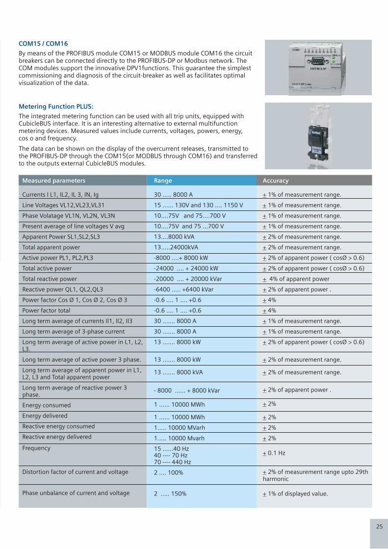
CMYK
CMYK
Overcurrent release ETU 76B
Mechanical RESET for reclosing lockout
Rated current module
Option: earth-fault module
Indicator: fault in overcurrent release
Indicator: cause of release
Graphical display
Control keys for setting the release parameters
Option: safety lock prevents pressing of reset button after overcurrent release
Earth-fault tripped
Indicator: Earth-fault alarm
Clear push button
Fields for noting setting values
Fields for noting setting values
Test socket
Test push button
Query push button
Indicators:Over Current release activatedOverload alarmCOMMUNICATION EXPANDED
Selection of the overcurrent releases
ETU 76B
ETU 45B
ETU 27B
ETU 25B
ETU 15B
8
Metering Function PLUS:
The integrated metering function can be used with all trip units, equipped with CubicleBUS interface. It is an interesting alternative to external multifunction metering devices. Measured values include currents, voltages, powers, energy, cos o and frequency.
The data can be shown on the display of the overcurrent releases, transmitted to the PROFIBUS-DP through the COM15(or MODBUS through COM16) and transferred to the outputs external CubicleBUS modules.
COM15 / COM16
By means of the PROFIBUS module COM15 or MODBUS module COM16 the circuit breakers can be connected directly to the PROFIBUS-DP or Modbus network. The COM modules support the innovative DPV1functions. This guarantee the simplest commissioning and diagnosis of the circuit-breaker as well as facilitates optimal visualization of the data.
Measured parameters
Currents I L1, IL2, IL 3, IN, Ig
Line Voltages VL12,VL23,VL31
Phase Volatage VL1N, VL2N, VL3N
Present average of line voltages V avg
Apparent Power SL1,SL2,SL3
Total apparent power
Active power PL1, PL2,PL3
Total active power
Total reactive power
Reactive power QL1, QL2,QL3
Power factor Cos Ø 1, Cos Ø 2, Cos Ø 3
Power factor total
Long term average of currents Il1, Il2, Il3
Long term average of 3-phase current
Long term average of active power in L1, L2, L3.
Long term average of active power 3 phase.
Long term average of apparent power in L1, L2, L3 and Total apparent power
Long term average of reactive power 3 phase.
Energy consumed
Energy delivered
Reactive energy consumed
Reactive energy delivered
Frequency
Distortion factor of current and voltage
Phase unbalance of current and voltage
Range
30 ….. 8000 A
15 …… 130V and 130 …. 1150 V
10….75V and 75….700 V
10….75V and 75 …700 V
13….8000 kVA
13…..24000kVA
-8000 ….+ 8000 kW
-24000 …. + 24000 kW
-20000 .... + 20000 kVar
-6400 ….. +6400 kVar
-0.6 …. 1 …. +0.6
-0.6 …. 1 …. +0.6
30 ……. 8000 A
30 ……. 8000 A
13 ……. 8000 kW
13 ……. 8000 kW
13 ……. 8000 kVA
- 8000 …… + 8000 kVar
1 …… 10000 MWh
1 …… 10000 MWh
1….. 10000 MVarh
1….. 10000 Mvarh
15 ……40 Hz40 ---- 70 Hz70 ---- 440 Hz
2 …. 100%
2 ….. 150%
Accuracy
+ 1% of measurement range.
+ 1% of measurement range.
+ 1% of measurement range.
+ 1% of measurement range.
+ 2% of measurement range.
+ 2% of measurement range.
+ 2% of apparent power ( cosØ > 0.6)
+ 2% of apparent power ( cosØ > 0.6)
+ 4% of apparent power
+ 2% of apparent power .
+ 4%
+ 4%
+ 1% of measurement range.
+ 1% of measurement range.
+ 2% of apparent power ( cosØ > 0.6)
+ 2% of measurement range.
+ 2% of measurement range.
+ 2% of apparent power .
+ 2%
+ 2%
+ 2%
+ 2%
+ 0.1 Hz
+ 2% of measurement range upto 29th harmonic
+ 1% of displayed value.
25
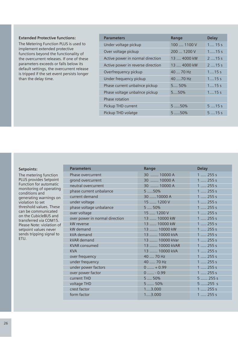
CMYK
CMYK
Application:
Properties:
Cost-effective intelligent allrounder for building and
all types of industrial applications- ”Cubicle BUS
integrated”.
1. Adjustable time-lag class for overload protection
2. Short-time delayed short-circuit protection,
adjustable from 1.25... 12 x I n
3. Instantaneous short-circuit protection adjusting
12 I /Max/Offn
4. Replaceable Rating Plug allows instant
adaptability to required plant currents, thus
ensuring overload protection of 100 A to 6300 A.
5. Switch-selectable characteristic of the overload
and short-time delay short-circuit range (current
discriminate) for finer selectivity conditioning to
downstream fuses or protective devices
6. Thermal memory as restart protection in case of
tripped motor circuits
7. Connectable and adjustable neutral conductor
protection
8. Modular earth-fault protection, with separately
adjustable alarm and trip function
9. Communication interface, metering function
(Plus), connection of external modules as option
or retrofit option.
10. Optional high-contrast display with viewing
angle adjustment
11. Overload indicator
12. Display of cause of trip through LED
13. Option for testing the release
14. Setting of protective functions by means of
rotary or slide switch.
example : 1000A - 3WL -> up to 1000Arating Plug 250A ; Ir setting = 0.4 X 250 = 100A
Sample configuration of an ETU 45B
Manual trip indicator
Text display with 15”inclination and rotatablethrough 180”
Micro-switch for switchselectable overloadcharacteristic curve
Rated currentmodule ratingplug
Earth-faultprotection module(retrofittable)
Rating Plug-in
7
250A 250A
315A 315A
400A 400A
500A 500A
630A 630A
700A 700A
800A 800A
1000A 1000A
1250A 1250A 1250A
1600A 1600A 1600A
2000A 2000A
2500A 2500A
3200A 3200A
4000A
5000A
6300A
size I size II size III
Setpoints:
The metering function PLUS provides Setpoint Function for automatic monitoring of operating conditions and generating warnings on violation to set threshold values. These can be communicated on the CubicleBUS and transferred via COM15. Please Note: violation of setpoint values never sends tripping signal to ETU.
Parameters
Phase overcurrent
grond overcurrent
neutral overcurrent
phase current unbalance
current demand
under voltage
phase voltage unbalance
over voltage
over power in normal direction
kW reverse
kW demand
kVA demand
kVAR demand
KVAR consumed
KVA
over frequency
under frequency
under power factors
over power factor
current THD
voltage THD
crest factor
form factor
Range
30 ……. 10000 A
30 ……. 10000 A
30 ……. 10000 A
5 …..50%
30 ……10000 A
15 …… 1200 V
5 …. 50%
15 ….. 1200 V
13 …… 10000 kW
13 …… 10000 kW
13 ……. 10000 kW
13 ……. 10000 kVA
13 ……. 10000 kVar
13 ……. 10000 kVAR
13 ……. 10000 kVA
40 …. 70 Hz
40 ….. 70 Hz
0 …… + 0.99
0 …… - 0.99
5 …. 50%
5 …… 50%
1….3.000
1….3.000
Delay
1 ….. 255 s
1 ….. 255 s
1 ….. 255 s
1 ….. 255 s
1 ….. 255 s
1 ….. 255 s
1 ….. 255 s
1 ….. 255 s
1 ….. 255 s
1 ….. 255 s
1 ….. 255 s
1 ….. 255 s
1 ….. 255 s
1 ….. 255 s
1 ….. 255 s
1 ….. 255 s
1 ….. 255 s
1 ….. 255 s
1 ….. 255 s
5 …… 255 s
5 ……255 s
1 ….. 255 s
1 ….. 255 s
Extended Protective functions:
The Metering Function PLUS is used to
implement extended protective
functions beyond the functionality of
the overcurrent releases. If one of these
parameters exceeds or falls below its
default settings, the overcurrent release
is tripped if the set event persists longer
than the delay time.
Parameters
Under voltage pickup
Over voltage pickup
Active power in normal direction
Active power in reverse direction
Overfrequency pickup
Under frequency pickup
Phase current unbalnce pickup
Phase voltage unbalnce pickup
Phase rotation
Pickup THD current
Pickup THD volatge
Range
100 …. 1100 V
200 … 1200 V
13 …. 4000 kW
13 …. 4000 kW
40 … 70 Hz
40 ….70 Hz
5…. 50%
5….50%
5 …..50%
5 …..50%
Delay
1…. 15 s
1…..15 s
2 ….15 s
2 ….15 s
1….15 s
1….15 s
1….15 s
1….15 s
5 ….15 s
5 ….15 s
26
CMYK
CMYK
Mechanical RESET for reclosing lockout
Rated current module
Rotary switch for setting value, overload releases
Rotary switch for setting value, instantaneous short-circuit releases
Rotary switch for setting value, short-circuit protection
Selector for earth-fault protection
Rotary switch for setting value, earth-fault protection
Rotary switch for delay earth-fault protection
Rotary switch for delay, short-circuit release
Rotary switch for delay, overload release
N-conductor overload
N-conductor protection on/off
Indicator: fault in over current release
Scroll down
Option: alphanumeric display
Option: safety lock prevents pressing of reset button after overcurrent release
Thermal memory on/off
Setting value N-conductor overload
2 4Transfer of overload characteristic I t1I t
Indicator: earth-fault tripped
Indicator: earth-fault alarm
Indicator: cause of release
Option: earth-fault module
Sealing ring
Rotary switch for setting value, earth-fault alarm
Test push button
Query push button
Clear push button
Test socket
Indicators:Over Current release activatedOverload alarmCommunicationExpanded
Scroll up
Overcurrent release ETU 45B
During the development of our over- current release we have consistently striven to ensure modularity. The following are just some modules that are simple to retrofit at any time
• Earth-fault protection module
• Communication modules
• Metering function
• Displays
• Rating plugs
This enables fast local adaptation to new network conditions. At the same time, the ETU are provided with new, innovative functions like:-
Rating Plug
The Rating Plug is a replaceable module that enables users to reduce the rated device current for optimum adaptation to the system; e.g. during startup of a plant section. The Rating Plug should be selected so that it roughly corresponds to the rated current of the system.
Switch-selectable or I t characteristic curve for the overload range.
The best possible protection for the overall switchgear assembly is achieved by ensuring optimum setting of the release characteristic. To achieve optimum selectivity of the upstream fuses or medium-voltage protective devices, the inclination of the characteristic curve can be switched over in the overload range.
Switch-selectable parameters
In the event of a sudden change in network conditions e.g. switchover of the transformers to generator operation or shut down of a part of the supply network at the change of shift, SENTRON WL now supports fast adaptation of the required protective parameters to the new circumstances.
Two release characteristics (parameter sets) that are independent of one another are stored on the ETUs. The transfer is executed in under 100ms and is initiated by an external signal.
I t2 4
DescriptionMicroprocessor based electronic over-current release (ETU)
3 and 4 pole, up to 6300 A fixed - mounted and withdrawable version
6
Waveform Memories:
The metering function Plus offers two additional functions:
• Two independent waveform memories.
• Harmonic analysis.
The two independent waveform memories can be used to analyze the current and voltages values at the time of the event.
The waveform memories can also be started or stopped individually through the communications channels (PROFIBUS-DP, MODBUS and Cubicle BUS).
Currents I L1, I L 2 , I L 3, I L N , I g
Voltages UL1; UL2: Ul3
The values that can be selected for one of the waveform memories are:
If the waveform memories are programmed to "recording" (standard setting), there is continuous recording until a previously defined event occurs. Then, the recording is stopped, and the current or voltage waveforms at the time of the event can be observed through a visual display (graphical LCD, laptop or PC). The time window is one second; the resolution is 1649 values/second.
27

CMYK
CMYK
User-friendly and precise:Planning with SENTRON
Standards:- The Sentron WL Circuit Breakers satisfy:
! IEC 60947 - 2, IS 13947 - 2
! DIN VDE 0660 Part 101
! UL 489 / ANSI C 37.13, UL 1066
! Climate Proof according to DIN IEC 68 Part 30 - 2
! CE Conformance
! Lloyd’s Register of shipping
5
Breaker Data Adapter BDA:
Switch ES Power:
Power Management:
The BDA is the first circuit breaker parameterisation device with integrated web server for the local programming, operation and monitoring of the SENTRON WL and SENTRON VL. The data may be read out on any output device with browser capabilities(e.g. Notebook), without the need for special software. The only system requirement for the input / output device is a standard browser with JAVA2 virtual machine. Once the BDA is connected to the circuit breaker, the browser is filled with Web pages from BDA and the data of the circuit breaker as shown in the following pictures. In addition, the BDAPlus incorporates an Ethernet interface for direct connection to the Ethernet/Intranet/Internet.
By means of the Switch ES Power software, the SENTRON WL and SENTRON VL circuit breakers can be parameterized, operated and monitored via PROFIBUS-DP. Operational philosophy of switches has been harmonized with that of the BDA. An object manager ensures complete integration into the SIMATIC world. Thus, SENTRON becomes an important component in Totally Integrated Automation(TIA).
SENTRON circuit breakers can be easily integrated into Power Management Systems. This facilitates efficient diagnosis, alarm, maintenance, cost center and load management. SENTRON circuit breakers play a key role in solutions provided by Totally Integrated Power(TIP).
Breaker Data Adapter - diagnostics
Cubicle BUS SENTRON WL
SENTRON VL
Modem
Modem
Notebook
You can use modems to extend the serial connection from the notebook to the BDA to enable the circuit breaker data to be accessed irrespective of your geographical location
28

CMYK
CMYK
Data that can be transmitted using COM15 / COM16or the breaker data adapter
Order code (Order no. Of circuit breaker + “-Z” )Order no.
Transmission of circuit breaker data to PROFIBUS-DP or Modbus - TCP / IP Network and Integration in higher-level visualization system possible e.g. In PCS7 Power Management Systems, WinCC (Incl. Add Ons, such as SMS radio server)
Transmission of circuit breaker data and software (i.e. HTML pages Incl. Data) to local output device or remotely controlled via the Ethernet/Intranet/Internet (no Integration option in higher-level visualization systems) e.g. for monitoring diagnostics, maintenance and configuration of individual circuit breaker
Use of the functionality of all CubicleBUS modulesE.g. Programming of the configurable digital output modules, status interrogation of digital input modules diagnostics, testing
Device Identification:Communication address, circuit breaker order no., Circuit breaker characteristic data (Size no. Of poles, rated current module etc.) ID numbers, release type, free text for equipment identifier and comments
Operating states:Closed / open signal spring store mechanism, tripped, readiness to close, Circuit breaker position (connected, test, disconnected and absent) for withdrawable circuit-breakers, PROFIBUS write protection on/off, free user input
Control commandsClosed / open circuit breakers, enable/disable free user output Reset trip signalClear event and trip logReset the min/max measured values, reset maintenance information
HistoryReadout of event log, readout of trip log
Maintenance InformationNumber of L, S, I releases and total, contact erosionNumber of switch operations under load and total operating hours
Event signaling Trip signal with identificatio of the current casuing the tripAlarm signaling (e.g. Overload) with incoming/outgoing informationAll named event signaling with time stamp
Configuration of protective functionsReadout of protective function parametersChange the settings of the protective function parameters through communication Parameter set changeover option (set A to set B)
Measured valuesPhase currents, each with min/max, valueTemperature in the circuit breaker with min/max. value Temperature in the cubicle with min/max, valueAll named measured values with time stamp
Additional transmittable circuit breaker data with integrated metering functions as mentioned on page 24, 25 & 26
+BDA/BDA Plus order no.
1)
1)
1)
1)
1)
1)
1)
2) 2)
1) Possible in connections with the COM15 / COM16 Module (Bus connection not required)
*
2) Possible with ETU 76B*
29
F01
BSS BSS COM15 / COM16 BDA
F02/F12
Transmittable circuit breaker data without integrated metering function
Application options
Transmittable circuit breaker data

CMYK
CMYK
Whether for rapid retrofitting, reduced
handling or optimal energy management-
anybody choosing SENTRON will profit
from clear and definite economic
Easy Planning:
Maximum Safety:
• Sentron WL is available in three frame sizes yet with identical door cutouts for all the frames and at same locations on the breakers to ensure standardization, symmetry and aesthetics in panel design.
• Software such as 'SIMARIS' designed to support you with evaluation, planning and calculation of the entire system, thus saving considerable time and energy in designing an electrical system.
• Contact erosion indicator on the main contacts will help to plan shutdown for the contact maintenance.
• 3 breakers frame size, 3 breaking capacity, single family and modular construction allows optimum selection of breaker.
• Distinct mechanical Ready-to-close indicator is provided as an inherent safety feature. This ensures safe switching ON of ACB and eases the diagnosis. Ready-to-close interlocking will verify the following condition:
• 3WL is switched OFF
• Storage spring is charged
• Undervoltage released is energized
• Shunt trip not energized
• Closing coil not energized
• No external interlocks activated
• Mechanical reclosing lockout reset
• Crank release lever ensures breaker removal from the guide frame only when the contacts are seperated.
• SAFE LOCK suitable for isolation. Castell key can be removed only when the contacts are seperated.
• Lockable guide frame on removal of circuit breaker available as standard.
• Lockable withdrawable circuit breaker to protect against unauthorized removal provided as a standard.
• High degree of IP protection class upto IP 55
• Mechanical reclosing lock out after overload or short-circuit release provided as standard feature.
• The front cover cannot be removed if the circuit breaker is in closed condition.
• 3WL confirms to isolation requirement as per DIN EN 60 947 - 2
• The Breaker Data Adapter(BDA) with integrated
Web-server allows local parameterization,
operation and observation of SENTRON circuit
breaker. BDA plus provides additional Ethernet
interface for remote diagnosis via LAN / WAN.
• The Switch ES Power software with the same
functionality via PROFIBUS - DP and with
integrated object manager for integration of the
SENTRON circuit breakers into SIMATIC system
System Solutions:
3
Advantages through Siemens SENTRON Communication:
Startup and Configuration:
Operator Control and Monitoring:
Power Management:
Maintenance and Service:
• PROFIBUS-DP enables faster and more reliable connections than conventional
point-to-point wiring. (Option with MODBUS also)
• Minimum plant down times for necessary expansion
• Simple startup test
• Transparent startup process with good documentation options
• Fast and reliable local configuration via PROFIBUS-DP or MODBUS or the Ethernet
/ Intranet / Internet with intelligent configuration software.
• Increase transparency in power distribution through transmission of current status
information, alarm signals and set point monitoring.
• Fault management enables a fast response when leaving the normal state.
Important message (e.g. trip signal and reasons) can be transmitted by SMS to the
cell phone of the plant personnel.
• Options for the central readout of parameters and their automatic transmission to
interchangeable circuit breakers minimizes fault liability and shortens down times.
• Effective diagnostics management e.g. through determinations of the precise
cause of fault and recording of the phase current.
• Remote control of the circuit breaker enables both the manual and automatic
switching on and off of plant parts.
• The balancing of load peaks and troughs allows the realization of energy imports
costs. Efficient load management enables the demand-orientated switching.
• Analysis of the archived power values (output curves) enables creation of a power
consumption profile. This can be the basis for future power procurement.
• The quality of energy (harmonics, flickers) can be logged and documented. This
enables effective power quality management.
• Cost center management makes power consumption more transparent for
commercial analysis. Cost can be clearly assigned and optimized.
• Information for preventive maintenance (e.g. number of switching operations,
operating hours, contact erosion estimation) enables timely and calculated
planning of necessary maintenance work. This reduces the risk of costly damage
to sensitive plant parts.
• The central control of maintenance work and the ability to SMS key information
considerably reduce costs for maintenance and service.
30

CMYK
CMYK
The Art of Intelligent Simplicity - Sentron WL
Circuit Breakers today are no longer simple
switching and protecting devices with ON/OFF
and trip indications. Users today are looking at
circuit breakers as a device, which integrates
switching, protection, metering and power
management including quality of power from
remote locations. Modern power systems are
also characterized by the methods used to
network circuit breakers - both with each
other and with other components.
Intelligent Modularity with Cost Savings:
• Same internal and external accessories for the entire range reducing inventory cost.
• Compact in size. A 6300 A 3WL requires only 800mm wide cabinet.
• Practically no deration till 55 Deg C with the permissible service temperature upto 70 Deg C. A 5000 A 3WL can deliver 5000 Amp even at 70 Deg C.
• High electrical life reduces the frequency of replacement of contacts.
• Unique rating plug facility allows a 3200 Amp 3WL to have thermal overload setting as low as 100A. This ensures complete protections even when the system is partially loaded.
Siemens offers SENTRON WL family, which
have a lot more to offer than even the so-
called “new circuit breaker” in the market. In
future, it will not only be possible to carry out
diagnosis and maintenance procedures
remotely on the Internet, but real-time
information about system malfunctions and
alarm signals will be made available
immediately to operating staff through SMS
and mobile phones.
This is not a fantasy for the future; in fact it’s hard reality.
This is Sentron. A new generation of circuit breakers from 100 A to 6300 A available in three
different sizes with the following advantages.
• Integrated CubicleBUS provides unmatched flexibility and cost economic solutions to all panels - metering, protections and annunciations requirements.
• Sentron stands for complete energy management - solution for continuous energy cost supervision and optimization - in short intelligent savings.
“SENTRON - Intelligent Simplicity”
In essence, modularity means: User-friendly
ease of planning, multiple use of standard
configurations - also, simple management of
changes and modification on site
2
The two available waveform buffer enable currents and voltages to be recorded on an event controlled basis.
31

CMYK
CMYK
The Intelligent Simplicity
Air Circuit Breaker
Sentron 3WL
Answers for industry.
Chennai4, Mahatma Gandhi Road, Chennai - 600034( : +91 44 28334000Fax: +91 44 28334088
Coimbatore7th Floor, East Wing, Global Towers1057, Avinashi Road, Coimbatore - 641018( : +91 422 4336300Fax: +91 422 4336310
Hyderabad5-9-19, Lakshmi Narsinh Estate, 4th FloorSecretariat Road, Opp. Secretariat, SaifabadHyderabad - 500004( : +91 40 23482500Fax: +91 40 23243145
Kolkata43 Shanti Palli, R B ConnectorEastern Metropolitan Bypass, Kolkata - 700042( : +91 33 24449000, 24428641-47Fax: +91 33 24449010 / 13
Lucknow28/45, Ashok Marg, Opposite Indira BhawanLucknow - 226001( : +91 522 4031022, 4031000Fax : +91 522 4031019
Mumbai130, Pandurang Budhkar Marg, WorliMumbai - 400018( : +91 22 24987000-02Fax: +91 22 24987312
Nagpur5th Floor, Landmark Building, Ramdas PethNagpur - 440010( : +91 712 6633000Fax: +91 712 6633111
New Delhi4A, Ring Road, I.P. Estate, New Delhi - 110002( : +91 11 42995000-09Fax: +91 11 42995030
PuneTower B / 701 - 705, ICC Trade Tower403A, Senapati Bapat Road, Pune - 411016( : +91 20 2570 6000Fax: +91 20 2570 6060
FaridabadHouse No 237, Sector-BFaridabad - 121006, HaryanaMobile: +91 987396350E-mail: [email protected]
Gurgaon 117-C, First Floor, Sector-30, Behind Jalvayu Vihar Gurgaon - 122001, HaryanaMobile: +91 9971091588E-mail: [email protected]
Guwahati G1, Hill View Apartment, Navagraha PathChenikuthi Hill Side, Guwahati - 781003, Assam( : +91 361 2663988Mobile: +91 9864037562E-mail: [email protected]: +91 9864110684E-mail: [email protected]
Hardwar 758, 1st Floor, Model Colony, Awas Vikas, Jwalapur Hardwar - 249407, UttarakhandMobile: +91 9897070133Fax: +91 1334 265491E-mail: [email protected]
Indore Indore - 452001, Madhya PradeshMobile: +91 9823011883E-mail: [email protected]
Jaipur 6, Park Street, Opp Pink City Petrol Pump, M.I.Road Jaipur - 302006, Rajasthan( : +91 141 2370274 / 2377956Fax: +91 141 2370482Mobile: +91 9829244313E-mail: [email protected]
Jalandar H.No 448R, First Floor, Pushpa NiwasNear Geeta Mandir, Model Town Jalandar - 144001, PunjabMobile: +91 9779194445E-mail: [email protected]
Jamshedpur 823, Udaigiri, Vijaya Heritage, Uliyan, Kadma Jamshedpur - 831005, Jharkhand( : +91 657 6451637Mobile: +91 9934311352E-mail: [email protected]
Jodhpur 371, Gauri House, Kamala Nehru NagarNear SBI Bank, Jodhpur - 342008, RajasthanMobile: +91 9828327200E-mail: [email protected]
Kanpur 106, Agarwal AparmentNear Hari Har Dham Mandir, Shyam Nagar Kanpur - 208013, Uttar Pradesh( & Fax: +91 512 2423348Mobile: +91 9839102434E-mail: [email protected]
Kolhapur B-7, Mahagaonkar Complex1147/E, Rajaram Road, Opp. Kamala CollegeKolhapur - 416001, Maharashtra( : +91 231 2536626Mobile: +91 9822558876E-mail: [email protected]
Kota 48, Model Town, Khedli Phatak Kota - 324002, RajasthanMobile: +91 9784842605E-mail: [email protected]
Ludhiana H.No 3746, First Floor, Sector 32-AChandigarh Road, Ludhiana - 141010, PunjabMobile: +91 9872317702E-mail: [email protected]
Ludhiana H.No 92, Lajpat Nagar, Near Bus StandLudhiana - 141010, Punjab( : +91 161 2770574Mobile: +91 9815502480E-mail: [email protected]
Madurai 8/12, Ground Floor, Sakhti Vellammal StreetSS Colony, Madurai - 625010, TamilnaduMobile : +91 9894617780E-mail: [email protected]
Nashik Flat No 2, Shivam Park, Rajiv NagarRane Nagar, Nasik-Mumbai HighwayNashik - 422009, MaharashtraMobile: +91 9822193204E-mail: [email protected]
Pondicherry 32, Second Floor, St. Theresa StreetPondicherry - 605001( : +91 413 4500101Mobile: +91 9840472727E-mail: [email protected]
Raipur Flat No.103, First Floor, Block B, Shilp EnclaveNear LAS Colony, Shankar Nagar Raipur - 492007, ChhattisgarhMobile: +91 9425057945E-mail: [email protected]
Rajkot D-3 Aalap Century, University RoadRajkot - 360005, GujaratMobile: +91 9825506962E-mail: [email protected]
Ranchi H-1/187, Harmu Housing Colony, HarmuRanchi - 834002, JharkhandMobile: +91 9234610953E-mail: [email protected]
Renukoot Above ICICI Prudentail Office, Patel NagarMurdhawa, Dist-SonebhadraRenukoot - 231217, Uttar PradeshMobile: +91 9838007897E-mail: [email protected]
Rourkela T-15, Civil Town, Rourkela - 769004, Orissa( : +91 661 2400880Mobile: +91 9437041724E-mail: [email protected]
Salem 3/25 Santosh Nagar, PACB BacksideChinnathirupathi, Salem - 636008, TamilnaduMobile: +91 9894617772E-mail: [email protected]
Sambalpur Pradhan Para, Near Jamkani MandirBeside LIC Div Off, AinthapalliSambalpur - 768004, Orissa( : +91 663 2541258Mobile: +91 9438529778E-mail: [email protected]
Surat 59, Ground Floor, Shreejinagar Part-1Dhabholi Char Rasta, Ved Road, KatagramSurat - 395004, GujaratMobile: +91 9925001779E-mail: [email protected]
Tiruchirappali T3, 3rd Floor, Vishranthi Daffodils ApartmentsOld Friends Eye Hospital, PuthurTiruchirappali - 620017, Tamilnadu( & Fax: +91 431 4030390Mobile: +91 9444911221E-mail: [email protected]
Trivandrum Sonu, TC9/2082, 5, Thamarakulam LaneSathamangalam, Trivandrum - 695010, KeralaMobile: +91 9895979604E-mail: [email protected]
Udaipur 303, Oasis Park, PP Singhal Marg, AmbavgarhUdaipur - 313001, Rajasthan( & Fax: +91 294 2430345Mobile: +91 9829039120E-mail: [email protected]
Vapi Flat No. 302, Samrajya IV, Royal ResidencyCharwada Road, Vapi - 396195, Gujarat( : +91 260 6451156Mobile: +91 9825147957E-mail: [email protected]
Vijayawada G-2,Shreya Tower, MoghalrajapuramNear Jammichettu CentreVijayawada - 520010, Andhra Pradesh( : +91 866 6629933Mobile: +91 9866463639E-mail: [email protected]
Visakhapatanam 84, Mount Moriah Residency, Waltair UplandsVisakhapatanam - 530003, Andhra Pradesh( : +91 891 2712535Mobile: +91 9849212555E-mail: [email protected]
Product upgradation is a continuous process.
Hence, data in this flyer is subject to change
without prior notice. For the latest information,
please get in touch with our Sales Offices.
Order No.: 102276646
SGR-01-115-023(This replaces SGR-01-115-008)
Customer Care Toll free no. 1800 220 987
Email: [email protected]
Sales offices:
Territory managers :
Your partners
Ahmedabad 3rd Floor, Prerna ArbourGirish Cold Drinks Cross Roads, Off. C. G. RoadAhmedabad - 380009( : +91 79 40207600Fax: +91 79 40207699
Bangalore1st Floor, Jyothimahal, #49, St. Marks RoadBangalore - 560001( : +91 80 22042000Fax: +91 80 22224131
ChandigarhSCO 189 - 191, 3rd Floor, Sector 17CChandigarh - 160017( : +91 172 4690300Fax: +91 172 4690399
AurangabadA9, Yogeshwari VrundavanNr. Malhar Chowk, Garkheda Parisar, Prema NagarAurangabad - 431210, MaharashtraMobile: +91 9766316446E-mail: [email protected]
BareillyBareilly - 243001, Uttar PradeshMobile: +91 9415012500E-mail: [email protected]: +91 9897070133E-mail: [email protected]
Baroda1st Floor, Vaniiya Bhavan, Race Course RoadBaroda - 390007, Gujarat( : +91 265 2325810/12, 6692110Mobile: +91 9825506963E-mail: [email protected]
BelgaumH.No.713, Narvekar Lane, Shahpur Belgaum - 590003, Karnataka( & Fax: +91 831 2495156Mobile: +91 9740277991E-mail: [email protected]
Bhilai C/o Mr. S.H SiddiquiSector-1, Street-9, Quarter No 1ABhilai - 490001, ChhattisgarhMobile: +91 9826127525E-mail: [email protected]
Bhubaneswar 109, Harapriya Apartment, Vivekananda MargBhubaneswar - 751002, Orissa( : +91 674 2430734Mobile: +91 9937009749E-mail: [email protected]: +91 9937097504E-mail: [email protected]
Calicut Dist : Kozhikode, Calicut - 673001, KeralaMobile: +91 9895052944E-mail: [email protected]
Cochin KG Oxford Busienss Centre39/4609, Third Floor, SreekandathRoad, Ravipuram Cochin - 682016, Kerala( : +91 484 4028611, 22Fax: +91 484 2380201Mobile: +91 9744511109E-mail: [email protected]
Deharadun 122, Vihar Lane No 1, Ajabpur Kalan Deharadun - 248001, UttaranchalMobile: +91 9760033117E-mail: [email protected]
Durgapur 4/6, Matangini Hazra BithiGround Floor, City center Durgapur - 713216, West Bengal( : +91 343 2605286Mobile: +91 9830185007E-mail: [email protected]
Siemens Ltd.,
Industry Sector
LV Control & Distribution Products
Thane Belapur Road, Thane - 400601
Fax: +91 22 27623729
E-mail: [email protected]
www.siemens.com/industry


