University of Kentucky University of Kentucky
UKnowledge UKnowledge
Theses and Dissertations--Computer Science Computer Science
2018
SDN-BASED MECHANISMS FOR PROVISIONING QUALITY OF SDN-BASED MECHANISMS FOR PROVISIONING QUALITY OF
SERVICE TO SELECTED NETWORK FLOWS SERVICE TO SELECTED NETWORK FLOWS
Faisal Alharbi University of Kentucky, [email protected] Digital Object Identifier: https://doi.org/10.13023/etd.2018.317
Right click to open a feedback form in a new tab to let us know how this document benefits you. Right click to open a feedback form in a new tab to let us know how this document benefits you.
Recommended Citation Recommended Citation Alharbi, Faisal, "SDN-BASED MECHANISMS FOR PROVISIONING QUALITY OF SERVICE TO SELECTED NETWORK FLOWS" (2018). Theses and Dissertations--Computer Science. 72. https://uknowledge.uky.edu/cs_etds/72
This Doctoral Dissertation is brought to you for free and open access by the Computer Science at UKnowledge. It has been accepted for inclusion in Theses and Dissertations--Computer Science by an authorized administrator of UKnowledge. For more information, please contact [email protected].

STUDENT AGREEMENT: STUDENT AGREEMENT:
I represent that my thesis or dissertation and abstract are my original work. Proper attribution
has been given to all outside sources. I understand that I am solely responsible for obtaining
any needed copyright permissions. I have obtained needed written permission statement(s)
from the owner(s) of each third-party copyrighted matter to be included in my work, allowing
electronic distribution (if such use is not permitted by the fair use doctrine) which will be
submitted to UKnowledge as Additional File.
I hereby grant to The University of Kentucky and its agents the irrevocable, non-exclusive, and
royalty-free license to archive and make accessible my work in whole or in part in all forms of
media, now or hereafter known. I agree that the document mentioned above may be made
available immediately for worldwide access unless an embargo applies.
I retain all other ownership rights to the copyright of my work. I also retain the right to use in
future works (such as articles or books) all or part of my work. I understand that I am free to
register the copyright to my work.
REVIEW, APPROVAL AND ACCEPTANCE REVIEW, APPROVAL AND ACCEPTANCE
The document mentioned above has been reviewed and accepted by the student’s advisor, on
behalf of the advisory committee, and by the Director of Graduate Studies (DGS), on behalf of
the program; we verify that this is the final, approved version of the student’s thesis including all
changes required by the advisory committee. The undersigned agree to abide by the statements
above.
Faisal Alharbi, Student
Dr. Zongming Fei, Major Professor
Dr. Miroslaw Truszczynski, Director of Graduate Studies
SDN-BASED MECHANISMS FOR PROVISIONING QUALITY OF SERVICE TOSELECTED NETWORK FLOWS
DISSERTATION
A dissertation submitted in partialfulfillment of the requirements forthe degree of Doctor of Philosophyin the College of Engineering at the
University of Kentucky
ByFaisal Alharbi
Lexington, Kentucky
Director: Dr. Zongming Fei, Professor of Computer ScienceLexington, Kentucky 2018
Copyright c© Faisal Alharbi 2018

ABSTRACT OF DISSERTATION
SDN-BASED MECHANISMS FOR PROVISIONING QUALITY OF SERVICE TOSELECTED NETWORK FLOWS
Despite the huge success and adoption of computer networks in the recent decades,traditional network architecture falls short of some requirements by manyapplications. One particular shortcoming is the lack of convenient methods forproviding quality of service (QoS) guarantee to various network applications. In thisdissertation, we explore new Software-Defined Networking (SDN) mechanisms toprovision QoS to targeted network flows. Our study contributes to providing QoSsupport to applications in three aspects. First, we explore using alternative routingpaths for selected flows that have QoS requirements. Instead of using the defaultshortest path used by the current network routing protocols, we investigate usingthe SDN controller to install forwarding rules in switches that can achieve higherbandwidth. Second, we develop new mechanisms for guaranteeing the latencyrequirement by those applications depending on timely delivery of sensor data andcontrol signals. The new mechanism pre-allocates higher priority queues inrouters/switches and reserves these queues for control/sensor traffic. Third, weexplore how to make the applications take advantage of the opportunity providedby SDN. In particular, we study new transmission mechanisms for big data transferin the cloud computing environment. Instead of using a single TCP path to transferdata, we investigate how to let the application set up multiple TCP paths for thesame application to achieve higher throughput. We evaluate these new mechanismswith experiments and compare them with existing approaches.
KEYWORDS: Software Defined Networking, Quality of Service, NetworkArchitecture, Multipath TCP
Author’s signature: Faisal Alharbi
Date: July 31, 2018

SDN-BASED MECHANISMS FOR PROVISIONING QUALITY OF SERVICE TOSELECTED NETWORK FLOWS
ByFaisal Alharbi
Director of Dissertation: Dr. Zongming Fei
Director of Graduate Studies: Dr. Miroslaw Truszczynski
Date: July 31, 2018

ACKNOWLEDGMENTS
I would like to express my sincere appreciation to my advisor, Dr. Zongming Fei,
for all the guidance and support I received from him. I am grateful to Dr. Fei for
giving me the opportunity to work with him and for providing endless support and
encouragement throughout the entire PhD journey.
I also want to thank the members of my Doctoral Advisory Committee: Dr.
Dakshnamoorthy Manivannan, Dr. Jinze Liu, and Dr. Yuan Liao for their guidance
and feedback.
Finally, I would like to thank my employer, King Abdulaziz City for Science and
Technology, for granting me the scholarship.
iii
TABLE OF CONTENTS
Acknowledgments . . . . . . . . . . . . . . . . . . . . . . . . . . . . . . . . . . iii
Table of Contents . . . . . . . . . . . . . . . . . . . . . . . . . . . . . . . . . . iv
List of Figures . . . . . . . . . . . . . . . . . . . . . . . . . . . . . . . . . . . vi
List of Tables . . . . . . . . . . . . . . . . . . . . . . . . . . . . . . . . . . . . vii
Chapter 1 Introduction . . . . . . . . . . . . . . . . . . . . . . . . . . . . . . 11.1 Overview . . . . . . . . . . . . . . . . . . . . . . . . . . . . . . . . . . 11.2 Contributions . . . . . . . . . . . . . . . . . . . . . . . . . . . . . . . 41.3 Organization . . . . . . . . . . . . . . . . . . . . . . . . . . . . . . . 5
Chapter 2 Background . . . . . . . . . . . . . . . . . . . . . . . . . . . . . . 62.1 Quality of Service . . . . . . . . . . . . . . . . . . . . . . . . . . . . . 6
2.1.1 IntServ . . . . . . . . . . . . . . . . . . . . . . . . . . . . . . . 62.1.2 DiffServ . . . . . . . . . . . . . . . . . . . . . . . . . . . . . . 72.1.3 QoS Metrics . . . . . . . . . . . . . . . . . . . . . . . . . . . . 82.1.4 QoS Routing . . . . . . . . . . . . . . . . . . . . . . . . . . . 10
2.2 Software-Defined Networking (SDN) . . . . . . . . . . . . . . . . . . 132.2.1 Early Efforts Prior to SDN . . . . . . . . . . . . . . . . . . . . 13
Routing Control Platform . . . . . . . . . . . . . . . . . . . . 13The 4D project . . . . . . . . . . . . . . . . . . . . . . . . . . 14Ethane . . . . . . . . . . . . . . . . . . . . . . . . . . . . . . . 16
2.2.2 SDN Model . . . . . . . . . . . . . . . . . . . . . . . . . . . . 172.2.3 SDN Characteristics . . . . . . . . . . . . . . . . . . . . . . . 182.2.4 SDN Benefits . . . . . . . . . . . . . . . . . . . . . . . . . . . 192.2.5 OpenFlow . . . . . . . . . . . . . . . . . . . . . . . . . . . . . 202.2.6 Open vSwitch . . . . . . . . . . . . . . . . . . . . . . . . . . . 22
Chapter 3 Improving the Quality of Service for Bandwidth-Demanding TrafficFlows . . . . . . . . . . . . . . . . . . . . . . . . . . . . . . . . . 24
3.1 Overview . . . . . . . . . . . . . . . . . . . . . . . . . . . . . . . . . . 243.2 Related Work . . . . . . . . . . . . . . . . . . . . . . . . . . . . . . . 253.3 An SDN-Based Framework for Setting Up Paths for
Bandwidth-Demanding Flows . . . . . . . . . . . . . . . . . . . . . . 263.3.1 Status Monitoring . . . . . . . . . . . . . . . . . . . . . . . . . 273.3.2 QoS-based Path Setup . . . . . . . . . . . . . . . . . . . . . . 29
3.4 Evaluation . . . . . . . . . . . . . . . . . . . . . . . . . . . . . . . . . 333.4.1 First Experiment . . . . . . . . . . . . . . . . . . . . . . . . . 33
Experiment Setup . . . . . . . . . . . . . . . . . . . . . . . . . 33
iv

Results . . . . . . . . . . . . . . . . . . . . . . . . . . . . . . . 333.4.2 Second Experiment . . . . . . . . . . . . . . . . . . . . . . . . 39
Experiment Setup . . . . . . . . . . . . . . . . . . . . . . . . . 39Results . . . . . . . . . . . . . . . . . . . . . . . . . . . . . . . 39
3.5 Summary . . . . . . . . . . . . . . . . . . . . . . . . . . . . . . . . . 40
Chapter 4 Provisioning Quality of Service to Latency-Sensitive Traffic Flows 424.1 Overview . . . . . . . . . . . . . . . . . . . . . . . . . . . . . . . . . . 42
4.1.1 Motivation . . . . . . . . . . . . . . . . . . . . . . . . . . . . . 424.1.2 Latency Measurements in SDN . . . . . . . . . . . . . . . . . 474.1.3 Queueing Disciplines . . . . . . . . . . . . . . . . . . . . . . . 48
4.2 Related Work . . . . . . . . . . . . . . . . . . . . . . . . . . . . . . . 494.3 An SDN-based Architecture for Supporting Latency-Sensitive Flows . 50
4.3.1 Admission Control . . . . . . . . . . . . . . . . . . . . . . . . 504.3.2 Queues Setup . . . . . . . . . . . . . . . . . . . . . . . . . . . 524.3.3 Installing OpenFlow Rules . . . . . . . . . . . . . . . . . . . . 534.3.4 Monitoring and Reporting . . . . . . . . . . . . . . . . . . . . 53
4.4 Provisioning QoS to Latency-Sensitive Flows . . . . . . . . . . . . . . 534.5 Performance Evaluation . . . . . . . . . . . . . . . . . . . . . . . . . 564.6 Summary . . . . . . . . . . . . . . . . . . . . . . . . . . . . . . . . . 58
Chapter 5 Improving Throughput of Large Flows Using Multipath TCP . . . 595.1 Overview . . . . . . . . . . . . . . . . . . . . . . . . . . . . . . . . . . 59
5.1.1 Motivation . . . . . . . . . . . . . . . . . . . . . . . . . . . . . 605.1.2 Data Center Topologies . . . . . . . . . . . . . . . . . . . . . 62
5.2 Multipath TCP . . . . . . . . . . . . . . . . . . . . . . . . . . . . . . 625.2.1 Congestion Control . . . . . . . . . . . . . . . . . . . . . . . . 65
5.3 Related Work . . . . . . . . . . . . . . . . . . . . . . . . . . . . . . . 695.4 SDN Based Architecture for Improving Throughput of Large Flows . 71
5.4.1 Load Balancing with OpenFlow Group Tables . . . . . . . . . 735.4.2 Routing Auxiliary Subflows . . . . . . . . . . . . . . . . . . . 755.4.3 Socket API for Creating Auxiliary Subflows . . . . . . . . . . 80
5.5 Evaluation . . . . . . . . . . . . . . . . . . . . . . . . . . . . . . . . . 855.5.1 Experiments Setup . . . . . . . . . . . . . . . . . . . . . . . . 855.5.2 Evaluation Results . . . . . . . . . . . . . . . . . . . . . . . . 87
5.6 Summary . . . . . . . . . . . . . . . . . . . . . . . . . . . . . . . . . 90
Chapter 6 Conclusion . . . . . . . . . . . . . . . . . . . . . . . . . . . . . . . 926.1 Future Work . . . . . . . . . . . . . . . . . . . . . . . . . . . . . . . . 93
Appendix . . . . . . . . . . . . . . . . . . . . . . . . . . . . . . . . . . . . . . 95
Bibliography . . . . . . . . . . . . . . . . . . . . . . . . . . . . . . . . . . . . 100
Vita . . . . . . . . . . . . . . . . . . . . . . . . . . . . . . . . . . . . . . . . . 105
v

LIST OF FIGURES
2.1 Simplified SDN architecture . . . . . . . . . . . . . . . . . . . . . . . . . 18
3.1 The SDN architecture for providing QoS support . . . . . . . . . . . . . 283.2 Match fields in OpenFlow . . . . . . . . . . . . . . . . . . . . . . . . . . 303.3 First experiment topology in Mininet . . . . . . . . . . . . . . . . . . . . 343.4 Throughputs with five critical flows . . . . . . . . . . . . . . . . . . . . . 353.5 Throughputs for critical flows without QoS routing module . . . . . . . . 363.6 Throughputs for critical flows with QoS routing module . . . . . . . . . . 373.7 Throughputs with six critical flows . . . . . . . . . . . . . . . . . . . . . 383.8 Utilization of the whole network . . . . . . . . . . . . . . . . . . . . . . . 383.9 Second experiment topology in Mininet . . . . . . . . . . . . . . . . . . . 403.10 Average throughput to the number of accepted flows . . . . . . . . . . . 41
4.1 Effects of the total delay on user satisfication (reprinted from [1]) . . . . 444.2 Provisioning QoS architecture to latency-sensitive flows . . . . . . . . . . 514.3 Example of different traffic classes . . . . . . . . . . . . . . . . . . . . . . 554.4 Experiment topology . . . . . . . . . . . . . . . . . . . . . . . . . . . . . 574.5 Measured latency of control traffic messages . . . . . . . . . . . . . . . . 57
5.1 Two examples of ECMP hash collision . . . . . . . . . . . . . . . . . . . 615.2 TCP and MPTCP protocol . . . . . . . . . . . . . . . . . . . . . . . . . 635.3 MPTCP subflows initiation . . . . . . . . . . . . . . . . . . . . . . . . . 655.4 Disjoint paths vs adaptive routing . . . . . . . . . . . . . . . . . . . . . . 735.5 SDN-based architecture for improving throughput of large flows . . . . . 745.6 OpenFlow group table . . . . . . . . . . . . . . . . . . . . . . . . . . . . 765.7 MPTCP option for MP JOIN SYN packet . . . . . . . . . . . . . . . . . 775.8 Creating new subflow with with DSCP . . . . . . . . . . . . . . . . . . . 845.9 Network topology . . . . . . . . . . . . . . . . . . . . . . . . . . . . . . . 865.10 Average throughput of large flows . . . . . . . . . . . . . . . . . . . . . . 885.11 Throughput of large flows (TM1) . . . . . . . . . . . . . . . . . . . . . . 895.12 Throughput of large flows (TM2) . . . . . . . . . . . . . . . . . . . . . . 895.13 Completion time of large flows (TM1) . . . . . . . . . . . . . . . . . . . 905.14 Completion time of large flows (TM2) . . . . . . . . . . . . . . . . . . . 90
vi

LIST OF TABLES
2.1 Sample of QoS routing problems solvable in polynomial time . . . . . . . 112.2 Sample of NP-Complete QoS routing problems . . . . . . . . . . . . . . . 13
3.1 Traffic flows . . . . . . . . . . . . . . . . . . . . . . . . . . . . . . . . . . 34
5.1 Multipath TCP Option subtypes . . . . . . . . . . . . . . . . . . . . . . 63
vii
Chapter 1
Introduction
1.1 Overview
Data communication played a critical role in many computer applications and has
become an essential part of our daily life, particularly due to the ubiquitous usage
of mobile devices. These applications with a communication component have a wide
range of requirements on the underlying computer networks. Traditional low data
rate file transfer or interactive remote login to a shared machine has very limited
requirements for the network, except reliability, which was handled by Transmission
Control Protocol (TCP) through retransmission of lost packets. In contrast, more
recently, applications such as video on demand, big data transfer, cyber physical
systems, cloud computing, etc., present more stringent requirements from the time
perspective, either measured as the latency or finishing time of data transfer, known
as Quality of Service (QoS) requirements. For example, teleconferencing applications
require audio/video data to be transferred with low packet delay to maintain the sense
of real-time interaction. Video streaming requires sufficient bandwidth to play the
video with little or no buffering. Otherwise it will cause interruption of playing the
video at the receiving end. They may have other QoS requirements such as low jitter
(variation in delay) and low packet loss ratio. For big data transfer applications, we
1

do not have strict deadline for packet delivery like in video streaming. However, we
do rely on the networks to provide enough bandwidth so that the transfer can finish
within a reasonable amount of time. In cyber physical systems such as smart grid and
home networking systems, we may need to monitor the status of equipment and send
control signals to initiate an operation. These sensor data and control signals need
to rearch their destinations in time to close the feedback loop, though the amount of
data can be small. All these present challenges to the underlying networks.
Traditional network architecture does not provide QoS support for data
communications. Even if the total network capacity can meet the requirements of
network applications, the quality of service delivered for these applications can be
unsatisfactory because of the best effort nature of the current network. There have
been quite a lot of studies on the mechanisms for providing QoS in traditional
networks. Most of them are theoretical studies and have not been deployed on the
Internet at any significant scale.
One of the reasons is perhaps that the proprietary protocols deployed in network
equipment by the vendors are mostly fixed and cannot be modified by end users.
Vendors of networking devices usually do not want to expose their internal
implementations to the public and tend to keep it closed, which make it difficult to
program the network. This limits flexibility and makes network management more
difficult. The network administrators cannot change their behaviors to meet the
requirements of end applications. The network researchers cannot modify the
software on network routers and switches to experiment, implement and deploy new
protocols to provide QoS support required by the applications.
Software Defined Networking (SDN) is a recently proposed new paradigm for
implementing network functions. It separates the control plane and data plane. Data
plane is in charge of data forwarding functions while the control plane determines
how the data are forwarded. The control plane function is centralized at the SDN
2

controller which installs forwarding rules that will be used by switches on the data
plane. The open standard allows users to write controller modules to define the
behavior of the data plane of the network. In addition, controllers provide northbound
API interface for users to write external application programs that interact with the
controller and have the capability to instruct what data forwarding switches should
do with the data packets.
SDN provides a new opportunity for researchers to experiment new network
mechanisms to provide the service required by applications. In this dissertation, we
explore new SDN mechanisms to provision QoS to targeted network flows. From our
analysis, we realized that there are two fundamental requirements for time-critical
applications, i.e., bandwidth and latency. For bandwidth, instead of using the
default destination-based routing algorithm, we explore alternative routing paths for
selected flows. We take advantage of the flexibility provided SDN and install rules
in the data forwarding switches, with the goal of using a forwarding path with
higher available bandwidth, instead of using the default shortest path used by the
current network routing protocols. To achieve the goal, we need to monitor the
status of the network and develop a method to figure out the current available
bandwidth on relevant links.
The other problem we want to address is latency. We are particularly interested
in those applications that need the sensor data and control signals to be transmitted
in a timely fashion so that the whole system can function properly. As a matter of
fact, we cannot solve the problem caused by the limit of the speed of light. However,
we do observe that one of the contributing factors is that these packets can wait
in the queue when there is competing traffic that uses the same path. We develop
a new mechanism that pre-allocates higher priority queues in routers/switches and
reserves these queues for control/sensor traffic. It is an elastic reservation in the sense
that if the bandwidth is not used by the reserved traffic, it can be used by others.
3

However, the reserved traffic has higher priorities. Therefore, it can guarantee that
the control/sensor traffic is not delayed at congested routers to achieve the goal of
keeping their end-to-end latency within the limit.
While the network can be equipped with mechanisms to install new routing
paths, we also explore how to make the applications take advantage of the
opportunity provided by SDN. From the application perspective, we study new
transmission mechanisms for big data transfer in the cloud computing environment.
Instead of using a single TCP path to transfer data, we investigate how to let the
application set up multiple TCP paths for the same application. We differentiate
short flows and long flows and adaptively determine whether to create subflows for
a TCP connection and how many auxiliary subflows to create. With the knowledge
about the network topology and available capacities provided by the SDN
controller, we develop the algorithm that improves the overall throughput for long
flows, without penalizing those short flows that do not need to use Multipath TCP
(MPTCP).
1.2 Contributions
In this dissertation, we propose three mechanisms that aim to improve the
provisioning of QoS to selected network flows. We identify the requirements of
certain network traffic and present methods and systems to achieve their
performance goals. These mechanisms are based on SDN. The proposed
mechanisms have been developed and evaluated on testbed environments. The main
contributions of this dissertation are:
• Improving the quality of service provided to traffic flows that have demands
for bandwidth. We propose an SDN-based solution for continuous monitoring
of network status and dynamically setting up forwarding paths for bandwidth-
demanding traffic flows.
4
• Provisioning quality of service to latency-sensitive traffic. We propose a
framework for managing and forwarding traffic flows that need to be
transmitted with higher priority to meet deadlines. This framework
accommodates different classes of traffic flows with different levels of
requirements.
• Maximizing the throughput of large flows by using Multipath TCP and SDN.
We propose a novel architecture that allows large traffic flows to achieve higher
throughput by utilizing multiple paths. Our approach enables applications to
dynamically create new subflows which are forwarded through least-congested
paths by the SDN controller.
1.3 Organization
The rest of this dissertation is organized as follows. Chapter 2 provides background
information related to QoS and SDN. Chapter 3 presents the SDN-based forwarding
solution for improving QoS to bandwidth-demanding traffic flows. Chapter 4
describes provisioning QoS to latency-sensitive traffic. Chapter 5 presents our
approach to improve the throughput of large flows by using Multipath TCP and
SDN. Chapter 6 provides the conclusion and possible future research.
5
Chapter 2
Background
2.1 Quality of Service
Providing Quality of Service was not one of the goals in the initial design of the
Internet. However, Internet applications (e.g., multimedia streaming, online-gaming,
teleconferencing, etc.) evolved over time and their need for QoS guarantee became
clear. Someone can argue that over-provisioning network resources to satisfy QoS
requirements is economically more feasible than replacing existing network
architecture. However, over the years there have been many efforts aimed at
providing QoS. Integrated Services (IntServ) and Differentiated Services (DiffServ)
were the two main proposals, although they were not successfully deployed on a
large scale.
2.1.1 IntServ
IntServ provides Quality of Service guarantee by reserving resources at each router
along the path travelled by the packets of a flow. There are two parts of this
architecture. First, the flow specification which describes the traffic flow and its
requirements. The flow is defined as “distinguishable stream of related datagrams
that results from a single user activity and requires the same QoS” [2]. Second, the
6

Resource Reservation Protocol (RSVP) [3] which is the signaling protocol used
between hosts and routers to request reservation of resources (e.g., bandwidth). In
order to provide the requested QoS, routers need to implement traffic control. The
IntServ architecture defines three components of traffic control: packet scheduler,
classifier, and admission control. Packet scheduler uses a set of queues to manage
forwarding different packet streams. The classifier maps each incoming packet into
some class. The admission control accepts or rejects a new QoS request for a traffic
flow.
Although IntServ provides QoS guarantee, it has some drawbacks that prevented
wide adoption of this architecture [4]. It requires maintaining flow state information
which is proportional to the number of flows. This affects the scalability, especially in
large networks like the Internet. It also requires all routers along the path to support
the three components of traffic control and RSVP protocol. These limitations lead
to the second proposal, DiffServ.
2.1.2 DiffServ
DiffServ was proposed to overcome the difficulties adopting IntServ. It provides
mechanisms for aggregating traffic flows into classes. The coarse-grained traffic
classes improve the scalability, in contrast with IntServs fine-grained traffic flows.
The classification is done by utilizing Differentiated Services Code Point (DSCP) [5]
field in the IPv4 and IPv6 headers. DSCP was introduced to replace ToS field in
IPv4. The classified packets are marked so they can be identified by routers and
forwarded accordingly. All packets that have the same DSCP value are grouped into
one class called Behavior Aggregate and will be treated equally by all routers in the
domain. The classifying and marking need to be performed only at the network
edge. However, all routers need to implement Per-Hop Behaviors (PHBs) which
describe properties for forwarding traffic classes (e.g., minimum bandwidth).
7
Per-Hop Behaviors ensure that high priority traffic will receive favorable treatment
over other traffic classes. This is usually achieved by implementing different priority
queues and traffic shaping (rate limiting). This architecture does not provide hard
QoS guarantee like IntServ.
2.1.3 QoS Metrics
Quality of service requirements are typically stated in service level agreements
(SLAs) that specify the guaranteed network performance to be provided for clients’
applications by service providers. Network performance is measured against a set of
attributes that include:
• Guaranteed minimum bandwidth. Throughput achieved by traffic streams is
affected by several factors like link capacity and network congestion. Providing
guaranteed minimum bandwidth to certain traffic flows (e.g., real-time video
streaming) ensures that such flows will deliver data as required to the receiving
end.
• Guaranteed maximum latency. End-to-end latency (delay) is the total time it
takes for a single packet to be transmitted from the source host to the
destination host. It involves transmission delay, propagation delay, queueing
delay and processing delay. Voice over IP (VoIP), teleconferencing and online
Internet gaming are examples of network applications that increased latency
affects their performance.
• Guaranteed maximum packet loss ratio. Network congestion can lead to
failure of delivering some packets. This can happen when buffers in network
devices reach their maximum capacity. In this case, routers and switches will
have to drop some packets. TCP, being a reliable transport protocol, ensures
the integrity of transmitted data by employing receipt acknowledgements and
8

retransmitting lost packets. However, dropped packets affect the performance
of TCP protocol as it is considered a congestion signal (identified by
retransmission timeouts and duplicated acknowledgements). In response to
congestion signal, the TCP congestion control algorithm will reduce the
sending rate of the TCP stream to avoid congestion.
• Guaranteed maximum jitter (variation in latency). Network conditions change
over time which can lead to different latency for packets belonging to the same
traffic flow. This variation in latency is not desirable and can affect the quality
of service for many applications like audio/video streaming and online Internet
gaming.
Apart from over-provisioning network resources (which is not a cost-optimal
solution), service providers can use mechanisms like resource reservation at each
node along the path taken by data packets and QoS-aware routing. Resource
reservation can involve giving higher priorities to certain traffic flows over other
traffic. QoS-aware routing tries to route traffic flows through paths that satisfy QoS
requirements.
Before going through the different types of QoS routing problems, we describe
the representation of the network and its properties. The network is represented as
a directed graph G(V,E), where V is the set of all nodes in the network and E is
the set of all links between nodes. Each link e ∈ E has associated properties: eb is
the available bandwidth capacity, ed is the delay, and el is the ratio of packet loss
(i.e., percentage of lost packets to the total number of packets; a ratio of 0 means no
lost packets). The accuracy of these attributes is very crucial to the performance of
QoS routing algorithms. The network state and measurements need to be updated in
order for routing algorithms to find the most suitable paths with sufficient resources
that meet required QoS parameters.
9

The path finding problem should return a path P from a source node s to a
destination node d that satisfies the required QoS parameters. We define the following
functions for a path P :
D(P ) =∑e∈P
ed
B(P ) = min∀e∈P
(eb)
L(P ) = 1−∏e∈P
(1− el)
The delay function is additive while the bandwidth function is concave [6]. The
packet loss ratio function is multiplicative but can be changed to additive by taking
logarithm of the ratio .
2.1.4 QoS Routing
The path finding problem in QoS routing can involve one or more QoS parameters.
Algorithms for QoS routing have been studied extensively in the literature [7, 8]. Each
required parameter can be either a constraint problem or an optimization problem.
For example, a bandwidth constrained problem is defined as finding a path P such
that each link in the path e ∈ P has available capacity larger than or equal to the
required bandwidth parameter. The widest path problem, a bandwidth optimization
problem, is defined as finding a path P that has the largest available capacity (i.e,
maximizing the bottleneck of the suitable path). Table 2.1 shows a sample list of
QoS routing problems that can be solved in polynomial time. For the simplest form,
a single QoS parameter, variations of shortest path finding algorithms (e.g., Dijkstra
algorithm or Bellman-Ford algorithm) can be used to solve the problem and find
a suitable path. Some composite parameter problems (e.g., constrained-bandwidth
10

least-delay problem) can be solved in polynomial time by running the shortest path
algorithm (weights of the graph edges are delay measurements) and removing the link
that has available capacity less than the bandwidth constraint.
Table 2.1: Sample of QoS routing problems solvable in polynomial time
Attributes Params Constraint Optimization Notes
Bandwidth Bmin B(P ) > Bmin Constrainedbandwidth
Delay Dmax D(P ) ≤ Dmax Constraineddelay
Packet loss Lmax L(P ) ≤ Lmax Constrainedpacket loss
Bandwidth arg maxP (B(P )) Widestpath
Delay arg minP (D(P )) Least delay
Packet loss arg minP (L(P )) Leastpacket loss
Bandwidth, Delay Bmin B(P ) > Bmin arg minP (D(P )) constrained-bandwidthleast-delay
Bandwidth, Packet loss Bmin B(P ) > Bmin arg minP (L(P )) constrained-bandwidthleast-packetloss
Delay, Bandwidth Dmax, Bmin D(P ) ≤ Dmax
B(P ) > Bmin
Constraineddelay-bandwidth
There are other composite-metric routing problems which are known to be NP-
Complete. These problems include [7, 9, 8, 10]:
• Multi-Constrained-Path (MCP) problems. For a given network G(V,E) where
each link (u, v) ∈ E has m additive weights wi(u, v) ≤ 0, i = 1, ...,m, and given
m constraints of additive parameters Ci, i = 1, ...,m, the problem is stated as
finding a path P ∈ P ′ where P ′ is the set of all feasible paths from source node
s to destination node d such that:
∀p ∈ P ′,Wi(p) ≤ Ci for i = 1, ...,m
11

where:
Wi(p) =∑
(u,v)∈p
Wi(u, v)
An example of the MCP problems is the constrained-delay constrained-jitter
problem. The goal is to find a path such that the delay is less than the delay
constraint parameter and the jitter is less than the jitter constraint parameter.
It should be noted that it is possible to have multiple paths that satisfy all
constraints. Any such path is considered a feasible solution for this problem.
• Multi-Constrained Optimal Path (MCOP) problems. For a given network
G(V,E) where each link (u, v) ∈ E has m additive weights
wi(u, v) ≤ 0, i = 1, ...,m, and given m constraints of additive parameters
Ci, i = 1, ...,m and an additive cost parameter Wk, the problem is stated as
finding a path P ∈ P ′ where P ′ is the set of all feasible paths from source
node s to destination node d such that:
(a) ∀p ∈ P ′,Wi(p) ≤ Ci for i = 1, ...,m
(b) Wk(P ) is minimized over all feasible paths satisfying (a).
where:
Wi(p) =∑
(u,v)∈p
Wi(u, v)
An example of MCOP problems is the constrained-delay least-jitter problem.
The goal is to find a path such that the delay is less than the delay constraint
parameter and the jitter is minimized.
Table 2.2 shows a sample list of NP-Complete QoS routing problems. For these
problems we have to use heuristics and approximation algorithms. Many of these
algorithms were discussed in [11, 7, 9, 12, 13].
12

Table 2.2: Sample of NP-Complete QoS routing problems
Metrics Params Constraint Optimization Notes
Delay,Jitter
Dmax, Jmax D(P ) ≤ Dmax
J(P ) ≤ Jmax
Constraineddelay-jitter
Delay,Packet loss
Dmax, Lmax D(P ) ≤ Dmax
L(P ) ≤ Lmax
Constraineddelay-packetloss
Delay,Jitter
Dmax D(P ) ≤ Dmax arg minP (J(P )) Constrained-delay least-jitter
Jitter,Packet loss
Jmax J(P ) ≤ Jmax arg minP (L(P )) Constrained-jitter least-packet loss
2.2 Software-Defined Networking (SDN)
2.2.1 Early Efforts Prior to SDN
Before SDN became a trending research topic in the area of networking, several
efforts that share certain similar ideas have been discussed and proposed to solve
the challenges of traditional network architecture. These efforts contributed in
different aspects to the currently popular SDN architectures. The ideas and
concepts range from decoupling control plane and forwarding plane to achieving
some level of programmability in networks [14, 15]. In this section, we will describe
briefly some of these efforts.
Routing Control Platform
The Routing Control Platform (RCP) [16] was proposed to solve some issues with
existing routing mechanism within autonomous systems (AS). The internal Border
Gateway Protocol (iBGP) architecture used within AS requires full-mesh
configuration which does not scale to large networks. While using a hierarchy of
Routing Reflectors (RR) helps in avoiding the scalability issue, it causes problems
such as protocol oscillations, persistent loops, and configuration complexity. These
problems make it difficult to manage the autonomous systems in terms of
13

configuration changes, diagnosis and troubleshooting of forwarding errors. These
problems happen because routing decisions are made by routers that do not have a
complete view of the whole network
In RCP architecture, the BGP decision process is implemented in a logically
centralized platform. The routing control platform is separate from the IP
forwarding plane. The main goal of this platform is to perform route selection
decisions centrally instead of making routers do this job. The RCP avoids the
aforementioned problems by computing routing decisions based on a complete view
of the whole network topology and the available routes. This information is
collected using the existing protocols BGP and Interior Gateway Protocol (IGP).
There are three modules in this RCP architecture: the IGP Viewer, the BGP
Engine, and the Route Control Server. The IGP Viewer maintains an up-to-date
view of the IGP topology. The BGP Engine is responsible for learning BGP routes
from each router. The Route Control Server uses the information obtained from the
other two modules to compute the best route for each router. After the route
selection process is executed centrally, the Route Control Server communicates with
routers through the BGP engine and installs new forwarding entries that correspond
to the selected routes. The communication between the Routing Control Platform
and routers is done through existing standard protocols (BGP and IGP) without
any modification or introduction of new protocols.
The 4D project
The 4D project was one of the earliest attempts to promote the initiative of
decoupling the network architecture into different planes. The clean slate 4D
approach to network control and management [17] proposed an extreme design
principle by separating the routing decisions logic and packet forwarding. It is
considered an extreme design point because the packet forwarding and the control
14

logic were tightly coupled in existing network devices. According to [17], the
problems with the current Internet architecture is caused by the complexity of the
control and management planes. This is due to the fact that the control logic and
packet forwarding are bundled into distributed routers and switches. Instead of
adding to previous building blocks to solve current problems, the 4D project team
suggested a clean slate approach that provides an alternative perspective to the
incremental evolution in computer networks.
The leading principles of this design approach focus on satisfying network-level
objectives, having network-wide topology view, and providing direct control over
the operation of networking devices. The proposed clean slate 4D architecture
decouples networking functions into 4 planes: data, discovery, dissemination, and
decision planes. The data plane is for processing individual packets based on
configurable rules dictated by the decision plane. The discovery plane is responsible
for gathering network topology information and other network measurements. The
dissemination plane serves as a reliable communication channel between the
decision plane and the data plane. It is used for installing rules on networking
devices to control how packets are processed. The decision plane acts like the
“brain” of the network and aims to replace the management plane in traditional
network architecture. It consists of logically centralized controllers hosted on
multiple servers. The main purpose of this plane is to make all decisions that
manage and control the network. To do this efficiently, it makes use of the
information gathered by the discovery plane (the global view of the network
topology and the real-time network measurements). The output of the decision
plane comes as packet-handling states that are configured in networking devices in
the data plane by the dissemination plane
15

Ethane
Ethane [18] is considered the direct predecessor of OpenFlow. The project
continued on the previous work of SANE [19]. SANE was also a clean slate design
approach focusing on enterprise security. However, SANE was difficult to deploy in
the real world because it requires changing the entire networking infrastructure.
Ethane mitigated this problem by supporting the incremental deployment. It does
not require changing the entire infrastructure and Ethane switches can be
incrementally deployed within existing network infrastructure.
The design of Ethane followed the lead of 4D project. It decouples the control
plane and the data plane. It also adopts a logically centralized controller that has
access to the whole network. The emphasis of this centralized controller is to enforce
global network policies. The other component is a layer of Ethane switches. These
switches are very simple and contain only a flow table and a secure communication
channel to the centralized controller. This simple design of switches is the foundation
of OpenFlow switches as we will see in the next section.
The Ethane switch forwards packets based on the matched flow table entry. If a
packet was not matched by any flow table entry, which is the usual case for the first
packet of any flow in this system, then it is forwarded to the centralized controller.
The controller will install the appropriate flow table entries on Ethane switches.
The installed flow table entries are based on analyzing the packet by the controller.
The main goal of the controller is to enforce global network policies. The design
objectives of Ethane (enforcing enterprise-level policies) and the size of their target
infrastructure (small campus networks) make the reactive mode a reasonable design
approach. However, this solution does not scale to large networks.
16
2.2.2 SDN Model
Software-Defined Networking is a new networking architecture that aims to create
a breakthrough improvement of how computer networks are designed and managed.
The basic concept of SDN is to separate networking functions into two different
planes: control plane and data plane. Traffic control decisions are made by application
programs (called controllers) in the control plane while forwarding traffic is done
by networking devices in the data plane. The communication between the control
plane and the data plane is done through standardized protocols. OpenFlow [20] is
the most successfully implemented SDN protocol. One of the benefits of having a
centralized network controller is the availability of global view of network topology
and monitoring its measurements. This allows the controller to make more educated
routing decisions. In the traditional network architecture, processing traffic is based
on packets. Network devices make forwarding decisions using address information in
data packets, but data usually is sent as a flow from host to host. Software-Defined
Networking uses the flow as the basic unit for handling traffic. Figure 2.1 shows a
simplified SDN architecture.
In the pre-SDN era, QoS routing decisions were mostly handled in network devices.
Proposed algorithms can be grouped into three categories: source routing (which
runs at the source node), distributed routing (calculating the path is distributed
among multiple nodes), and hierarchical routing (routing logic and network state
are distributed among clusters of nodes). The advantages and disadvantages of each
approach were discussed in the literature [7]. However, the advent of SDN changes
the way of handling routing decisions. Network nodes do not need to maintain a
global state of the network or compute QoS routes. These tasks can be delegated to
the control plane.
17

Figure 2.1: Simplified SDN architecture
2.2.3 SDN Characteristics
Software-Defined Networking has some distinguishing characteristics that define how
it is different from the traditional networking architecture. These characteristics
include [14, 21]:
• Decoupling control and forward functions. While these two functions are tightly
coupled in traditional networking devices, the separation between control plane
and data forwarding plane is a key feature of Software-Defined Networking.
• Logically centralized network management. The management tools and
protocols are distributed in the traditional network architecture in a way that
makes the management task very difficult and sometimes inefficient.
18

• Open standards. To promote the development of new network protocols and
tools, popular Software-Defined Networking architectures are based on open
standards such as the OpenFlow [20] protocol.
• Programmable network. The ability to program the network was one of the
important motivations for Software-Defined Networking. Traditional network
architectures provide limited support to achieve a restricted level of network
programmability.
• Flow-based. In the traditional network architecture, processing traffic is based
on packets. Network routers and switches make forwarding decisions using
address information in data packets, but data usually is sent as a flow from
host to host. Software-Defined Networking uses the flow as the basic unit for
handling traffic.
2.2.4 SDN Benefits
Software-Defined Networking promises many benefits for the next generation of
computer networks. These benefits include [14, 21]:
• Easier management by separating network control logic from the underlying
networking devices (e.g., switches, routers, middleboxes) and providing central
management tools for network administrators.
• Innovation in new network protocols and tools. Using open standard protocols
enables the creation of new innovative products.
• Flexibility and agility of network configurations and applying new changes in
response to traffic requirements.
19

• Testing and deploying new network protocols and algorithms is a lot easier
compared to the traditional network architectures where dedicated
infrastructure is usually required for testing purposes only.
• Network function virtualization. Many network functions that are usually
implemented in dedicated devices (e.g., firewalls, load balancers, intrusion
detection systems, etc.) can be implemented in virtual machines.
2.2.5 OpenFlow
The OpenFlow [20] architecture follows the principle of separation between control
plane and data forwarding plane. Initially, OpenFlow was proposed to enable
researches to develop and test new network protocols and solutions on campus
networks. It is currently the most popular architecture for Software-Defined
Networking. Several commercial products provide support for OpenFlow
architecture. The bottom layer of this architecture, the data forwarding plane,
consists of OpenFlow switches. The OpenFlow switch contains at least three main
components. First, one or more flow tables. Second, a secure communication
channel between the switch and the controller. Third, support for the OpenFlow
protocol.
The flow entries in the flow table determine how a matching packet is processed.
For example, a packet can be forwarded to a specific port, encapsulated and sent to
the controller, or dropped. Each flow entry is typically constructed from the following
fields:
• Match fields: to define the rule packets belonging to the flow. These rules
usually match information found in packet headers or port number.
• Instructions: the action associated with the rule that specifies how the packet
is processed.
20

• Counters: statistics in the form of counters of the flow (e.g., number of
received/transmitted packets and bytes, duration of the flow).
• Priority: to specify the matching precedence of flow entries.
• Timeouts: the switch when the flow entry is expired. There are two types of
timeouts: hard timeout (the total time from installation) and soft timeout (the
idle time).
• Cookie: A data item chosen by the controller. Cookies do not impact processing
packets in the data plane. The controller can use cookies to filter flows based
on different types of tasks or based on which module/application in the control
plane installed them.
• flags: used for managing flow entries. For example, the flag
OFPFF_SEND_FLOW_REM is used for sending a message to the controller when
the corresponding flow entry is removed.
When a packet is received by an OpenFlow-enabled switch, its properties are
matched against a set of attributes stored in records of the flow tables. If a match
is found then the corresponding instructions for the table record are added to the
actions list. If a packet is matched by more than one record, the instructions of
the record with the highest priority are added to the actions list. An OpenFlow
switch can have multiple flow tables which are processed as a pipeline. It is possible
to have an instruction to direct a packet explicitly to another table. If the packet
did not match any flow record it is called a table-miss. The applied actions of the
table-miss depends on the configuration of the table. The packet can be encapsulated
and forwarded to the controller. However, it is possible to process the non-matching
packet using IP forwarding if the switch supports both OpenFlow and non-OpenFlow
forwarding.
21

The OpenFlow protocol defines the communication between the controller and
the OpenFlow switch. It contains a set of protocol messages that are exchanged
between the controller and the switches over a secure communication channel. Using
OpenFlow protocol, the remote controller can install, update, or remove flow records
in flow table inside the OpenFlow switch. It also enables the controller to retrieve
statistics. Many products and tools were developed using OpenFlow architecture.
Most of the early systems of Software-Defined Networking were designed to
operate on a reactive mode (e.g., Ethane). In the reactive mode, the first packet of
the flow is forwarded to the controller that installs new flow entries to control the
remaining packets of that flow. In the proactive mode, systems do not require
sending the first packet to the controller. Instead, the controller changes the flow
entries based on other inputs like topology changes or responding to statistics.
OpenFlow architecture supports both reactive mode and proactive mode. In the
reactive mode there will be a performance delay since the first packet of each flow
will need to go to the controller for further processing. While this performance
penalty can be affordable in small campus networks, it does not provide a realistic
solution for large production networks. It also increase the challenge of scalability
as the controller must process larger number of packets in larger networks.
2.2.6 Open vSwitch
Open vSwitch [22, 23] is a software implementation of network switch that can be
used in a virtualized environment. It provides connectivity between virtual machines
and physical network interfaces within a hypervisor. This software switch provides
support for multiple networking protocols and standards, including OpenFlow. Open
vSwitch can operate like a basic L2 switch or can be integrated into a virtualized
environment. To support virtualized deployment, Open vSwitch exports interfaces
for manipulating forwarding tables and managing configuration states. This allows
22

remote processes to access and modify configurations and forwarding tables directly.
Open vSwitch also exports a local connectivity management interface which allows
the virtualization layer to manipulate its topological configuration. Open vSwitch can
be used in creating a single logical switch across multiple Open vSwitches running
on separate physical servers. It is also helpful in overcoming the limitation of virtual
machine mobility between different IP subnets.
23
Chapter 3
Improving the Quality of Service
for Bandwidth-Demanding Traffic
Flows
3.1 Overview
Communication technology is one of the key enabling components of current and
future applications by providing reliable and efficient two-way communication
capabilities. Different applications generate large volumes of data traffic with
different quality of service requirements. They can be delay sensitive, bandwidth
sensitive or can be served by best-effort service. Real time control in industrial
systems can be easily achieved by using dedicated networks. However, using
dedicated networks is not a feasible solution in more generic network settings. The
packet-switched network architecture serves multiple applications where different
data traffic streams coexist with each other. New challenges faced by the existing
network infrastructure and control protocols include strict time requirement, high
reliability, and flexibility of control.
In this chapter, we develop a framework based on software-defined networking
24
for providing critical communication services. The SDN architecture is generally
considered most applicable to those application domains that an administrator has
complete control. Examples includes data centers, home networking, smart grid
applications, distribution automation and microgrids.
We can divide data traffic into two categories. One is the traffic that does not
have QoS requirements (called best-effort traffic or best-effort flows) and the other
is the traffic that have one or more QoS requirements such as bandwidth, delay,
delay jitter or packet loss ratio (called critical traffic or critical flows). The focus
of this chapter is on providing better service for critical flows that have bandwidth
demand, by dynamically setting up forwarding paths in the data plane. To that end,
the control program will monitor the status of the network and direct critical flows
over a better path by installing OpenFlow rules on the switches. We develop a path
searching algorithm and implement it as a module for the Floodlight controller [24].
The performance evaluations show that our approach can significantly improve the
throughput obtained by the critical flows, compared with the shortest path routing
algorithm used in current networks.
3.2 Related Work
The study of the QoS routing problem for multimedia applications can be dated
back to the work by Wang and Crowcroft [6]. They proved that finding a path
satisfying multiple additive metrics is NP-complete. They then proposed several
path computation algorithms, using either centralized source routing or distributed
hop-by-hop routing.
OpenQoS [25] is a controller design proposed to provide QoS guarantee for
multimedia applications. Network traffic is divided into multimedia flows and data
flows. OpenQoS implements dynamic routing for multimedia traffic to place them
on routes with guaranteed QoS. Data flows are handled using the traditional
25

shortest-path algorithm. The dynamic QoS routing is formed as the Constrained
Shortest Path (CSP) problem. It is formulated as finding a path which minimizes a
cost function subject to the total delay to be less than or equal to a specified value
Dmax (required by the multimedia flow). The cost metric for a link is the delay
measure plus the congestion measure. The congestion measure for each link depends
on the bandwidth utilization. It is set to 0 if the bandwidth utilization is less than
70%. However, in their proposal they used the hop count as the delay measure (i.e.,
the delay measure for all links is set to 1). While OpenFlow does not provide
support for gathering delay measurements, there are methods to achieve this task,
such as using probe packets. Since the CSP problem is NP-Complete, they proposed
using an approximation algorithm called Lagrangian Relaxation Based Aggregated
Cost (LARAC) algorithm [11] to find a good route. They implemented their QoS
routing on top of Floodlight controller.
VSDN (Video over SDN) [26] is another framework that aims at providing QoS
guarantee for multimedia flows in video streaming applications. It exposes some QoS
APIs to be used by both sender and receiver to request QoS for video streaming.
The centralized controller calculates a feasible path based on QoS requirements and
keeps monitoring network resources. However, VSDN requires modifying the existing
OpenFlow switches to support their proposed guaranteed service.
3.3 An SDN-Based Framework for Setting Up Paths for
Bandwidth-Demanding Flows
We represent the network as a directed graph G(V,E), where V is the set of all
OpenFlow switches and end hosts in the data plane and E is the set of all links
between these nodes. Links are represented as ordered pairs. For example, (v1, v2)
represents the single link in the topology where v1 is the source node and v2 is the
destination node. Each link is assigned the attribute of computed available capacity.
26

Note that the attributes can be different for links (v1, v2) and (v2, v1) because of
asymmetric links.
We formulate the problem as finding the shortest path from a source node s to a
destination node d such that the minimum available capacity of path links is larger
than the required capacity for the critical traffic flow.
We develop two modules (Status Monitoring and QoS-based Path Setup) for the
Floodlight controller, as shown in Figure 3.1. Floodlight offers a flexible module
loading system that allows extensions. The basic modules of the floodlight interact
with the OpenFlow switches. The extension modules can use the functionalities
provided by basic modules. The first extension module is Status Monitoring, which
collects network measurements as a basis for the second module. They include usage
information, such as used bandwidth, for each link. The second extension module
is QoS-based Path Setup, which calculates a path using the topology of the network
graph and collected measurements. It finds a path that satisfies a specific bandwidth
requirement and installs OpenFlow rules on the switches in the data plane.
3.3.1 Status Monitoring
The OpenFlow switch specification [27] defines a list of counters that must be
supported by OpenFlow-capable switches. The list includes per-flow counters and
per-port counters. We are interested in the per-port counters, specifically the
transmitted bytes counters. The controller can retrieve the values of these counters
by sending a statistics request message to the switch and getting a reply message
that contains the number of transmitted bytes at the time of the request. It should
be noted that these measurements will not be 100% accurate by the time the
controller receives them, due to the delay of the request-reply messages and the
processing delay at the controller. Nonetheless, they give a good estimate of the
usage of the links being monitored.
27

Figure 3.1: The SDN architecture for providing QoS support
The controller application collects statistics measurements (counters of
transmitted bytes) periodically. Each link in the network topology has a source
switch-port and/or a destination switch-port. The used bandwidth of a link is
obtained by dividing the number of transmitted bytes from the source switch-port
of that link over the time interval 1. The difference between the values of two
consecutive reply messages for the switch-port counter is used to calculate the
consumed bandwidth of the corresponding network link. The OpenFlow
specification does not include timestamps for measurements reply messages. Hence,
the time interval is set at the control plane level as the difference between the
timestamps of sending these requests to the switch. The time interval should be
chosen carefully. It has to be small enough so that the calculated bandwidth is
relatively up-to-date. It also cannot be too small; otherwise the controller and
1Another approach is to use the received bytes counter of the destination switch-port.
28

switches will be burdened by the overhead of processing these messages. An interval
between 5 and 10 seconds is a reasonable choice.
We obtain network topology information from Floodlight module topology
manager. For each link we subtract the calculated bandwidth from its maximum
capacity to get the available capacity used in the routing algorithm. To get the
maximum capacity of the link, the controller can send a request to the switch
asking about the features of a port (or multiple ports) in the switch. The advertised
port capacity is one of the port features.
3.3.2 QoS-based Path Setup
There are many measures to specify different aspects of QoS requirements. In this
chapter, we only consider the traffic flows demanding bandwidth requirement. These
flows, which we call them critical flows, must be placed on network paths that have
sufficient bandwidth capacity, while the non-critical flows are handled as best-effort
and routed using the shortest-path algorithm. The critical traffic can be distinguished
from best-effort traffic by matching packets from the flow against a set of fields.
OpenFlow defines a list of match fields that can be used to differentiate between
flows. The list of required fields that must be supported by OpenFlow switches
include Ingress port, source and destination MAC addresses, MAC type, source and
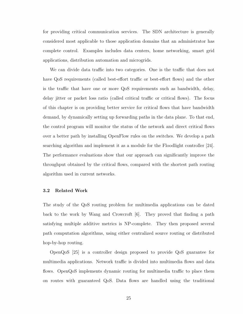
destination IP addresses, protocol type, and transport layer ports (see Figure 3.2).
There are other fields stated in the OpenFlow specification, but switches are not
required to support all of them. A flow can be identified by setting match rules
against any number of these fields. For example, we can define critical traffic to be
all TCP traffic from a specific IP address, or all TCP traffic within a pre-defined
source port range.
The first packet of each flow is encapsulated inside a PACKET IN OpenFlow
message and forwarded to the controller. This implies that the controller processes
29
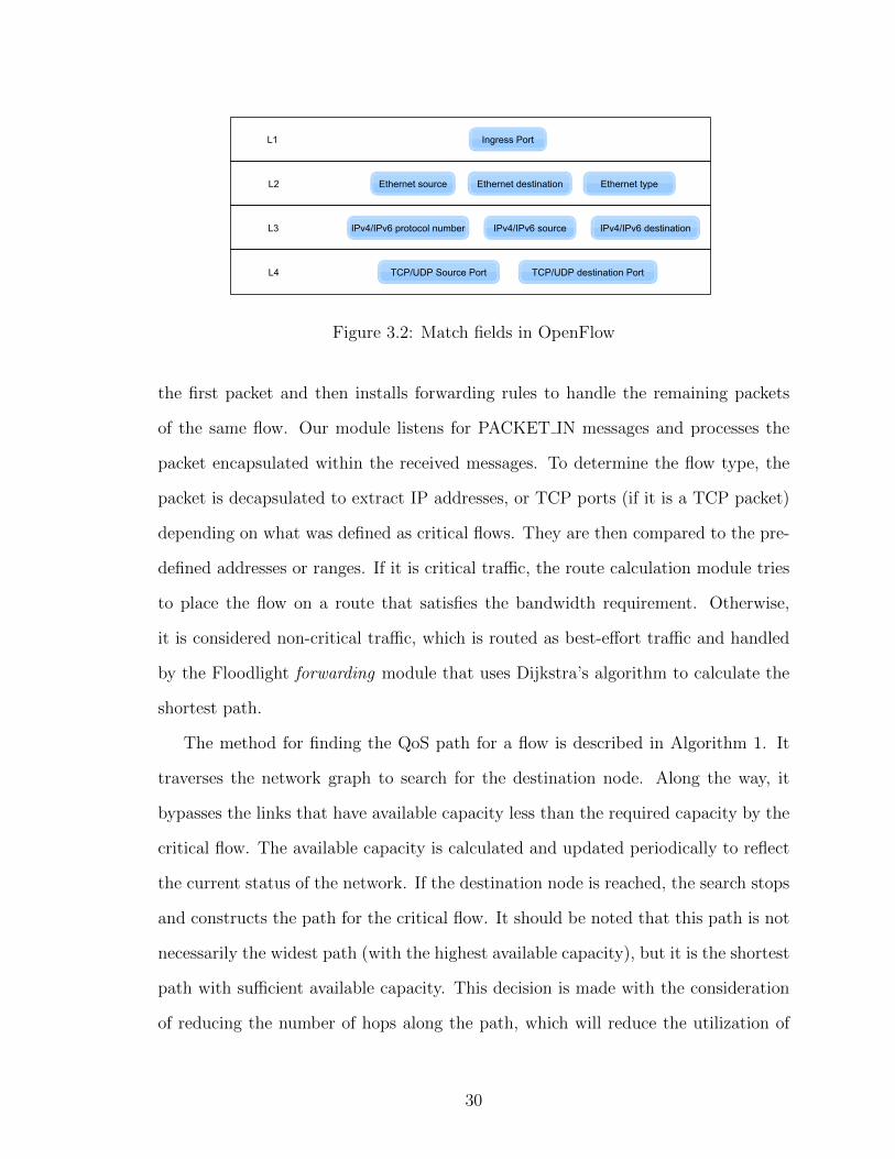
Figure 3.2: Match fields in OpenFlow
the first packet and then installs forwarding rules to handle the remaining packets
of the same flow. Our module listens for PACKET IN messages and processes the
packet encapsulated within the received messages. To determine the flow type, the
packet is decapsulated to extract IP addresses, or TCP ports (if it is a TCP packet)
depending on what was defined as critical flows. They are then compared to the pre-
defined addresses or ranges. If it is critical traffic, the route calculation module tries
to place the flow on a route that satisfies the bandwidth requirement. Otherwise,
it is considered non-critical traffic, which is routed as best-effort traffic and handled
by the Floodlight forwarding module that uses Dijkstra’s algorithm to calculate the
shortest path.
The method for finding the QoS path for a flow is described in Algorithm 1. It
traverses the network graph to search for the destination node. Along the way, it
bypasses the links that have available capacity less than the required capacity by the
critical flow. The available capacity is calculated and updated periodically to reflect
the current status of the network. If the destination node is reached, the search stops
and constructs the path for the critical flow. It should be noted that this path is not
necessarily the widest path (with the highest available capacity), but it is the shortest
path with sufficient available capacity. This decision is made with the consideration
of reducing the number of hops along the path, which will reduce the utilization of
30

network switches and (in most cases) reduce latency.
After the path is found, corresponding OpenFlow rules will be generated and
installed by the Floodlight controller to the switches along the path. If the search fails
to find a path that satisfies the required bandwidth capacity it returns null. In this
case, the critical traffic flow cannot be placed on a route that meets its requirement.
Instead, it will be handled like normal traffic and forwarded along the shortest path
using Dijkstra’s algorithm.
We implemented the QoS routing algorithm as a module inside the Floodlight
controller [24]. Floodlight is Java-based controller that was forked from Beacon [28],
one of the first OpenFlow controllers. Floodlight offers a flexible module loading
system that allows extensions. There are two methods for writing applications on
top of Floodlight controller. First, the application can be written in Java as an
embedded module inside Floodlight. It can communicate with other built-in modules
and consumes the provided services directly. Second, an application can be written
in any language and communicate with Floodlight using REST APIs. It can retrieve
information and invoke services by utilizing the exposed Floodlight REST APIs. We
chose to implement the QoS routing algorithm as a Java module inside Floodlight. If
someone wants to develop an application that is large and performs computationally
expensive actions, then it would be more suitable to write it as a separate application
that can run on a different server and communicate with Floodlight using its exposed
REST APIs.
31

Algorithm 1 FindQoSPath(source, destination, reqCapacity)queue← emptyvisited← emptyprevLink ← emptyqueue.add(source)visited.add(source)dstFound← falsewhile (queue is not empty) and (dstFound = false) do
node← queue.remove()for link ← topologyLinks.connectedto(node) do
neighbor ← link.getDestination()if visited.contains(neighbor) then
continueend ifif getAvailableCapacity(link) < requiredCapacity then
continueend ifqueue.add(neighbor)visited.add(neighbor)prevLink[neighbor]← linkif neighbor = destination then
dstFound← truebreak
end ifend for
end whileif dstFound = true then
route← emptynode← destinationwhile (node 6= source) do
route.addF irst(prevLink[node])node← prevLink[node].getSource()
end whilereturn route
elsereturn null
end if
32

3.4 Evaluation
3.4.1 First Experiment
Experiment Setup
For testing the QoS routing algorithm we used Mininet [29] with the software Open
vSwitch [22]. Mininet is an emulation tool that provides a virtualized environment
for prototyping and evaluating SDN applications. It uses lightweight virtualization
techniques at the operating system level to emulate hosts, links, switches, and
controllers. We wrote Python scripts using Mininet Python APIs to create the
network topology. Mininet can be configured to work with software switches. We
chose Open vSwitch due to its flexibility and good support for OpenFlow switch
specification.
To test our QoS routing module, we created a network topology with 8 switches
(Open vSwitch) and 22 hosts in Mininet. The topology is shown in Figure 3.3. The
bandwidth of the links between switches is set to 25 Mbps and the bandwidth of the
links between switches and hosts is set to 10 Mbps. Mininet uses the traffic control
command in Linux tc to specify the bandwidth. After that, we generated 14 flows
using iperf3 [30]. Five of these flows were critical flows. Table 3.1 shows the list of
flows in this experiment. Using Python script, we started the Mininet topology and
then generated the flows in the order shown in the table. The Floodlight controller
was running on a different machine connected to the Mininet host.
Results
First, we ran this experiment with QoS routing module disabled in Floodlight. Then
we ran the same experiment with QoS routing module enabled. Since the link between
switches and hosts has the capacity of 10 Mbps, the maximum speed a critical flow
can send is 10 Mbps. The measured throughput for each flow in both cases is shown
33
Figure 3.3: First experiment topology in Mininet
Table 3.1: Traffic flows
Flow Source Destination Start time Is Critical Size1 h31 h42 2 No 150 MB2 h41 h32 3 No 140 MB3 h32 h41 4 No 145 MB4 h42 h31 7 No 135 MB5 h11 h71 22 Yes 135 MB6 h71 h61 23 No 140 MB7 h43 h33 25 No 120 MB8 h33 h81 41 Yes 130 MB9 h74 h63 42 No 115 MB10 h12 h51 57 Yes 125 MB11 h72 h62 59 No 125 MB12 h51 h83 76 No 100 MB13 h13 h82 91 Yes 120 MB14 h73 h21 106 Yes 110 MB
in Figure 3.4.
The experiment results show that all five critical flows achieved much smaller
throughput when the Floodlight controller was running without the QoS routing
module. The average rates for critical flows were 8046 kbps (flow No. 5), 7248 kbps
34

1 2 3 4 5 6 7 8 9 10 11 12 13 14Traffic flows
0
2000
4000
6000
8000
10000
Avge
rage
ban
dwid
th (k
bps)
Avg w QoS
Avg w/o QoS
Without QoSWith QoS: Non critical flowWith QoS: Critical flow
Figure 3.4: Throughputs with five critical flows
(flow No. 8), 7272 kbps (flow No. 10), 6838 kbps (flow No. 13), and 7024 kbps
(flow No. 14). The measurements improved in the case with the QoS routing module
enabled. The throughputs for critical flows were 9408 kbps (flow No. 5), 9374 kbps
(flow No. 8), 9446 kbps (flow No. 10), 9565 kbps (flow No. 13), and 9572 kbps (flow
No. 14).
Figures 3.5 and 3.6 show the measured throughput for each critical flow as reported
by iperf3 with an interval of 10 seconds. The x-axis denotes the lifetime for each flow
(its duration), not the time for the experiment. In the first experiment, flow No.
10 (from h12 to h51 ) was routed through S1, S3, and S5. Link (S3, S5) already
had 2 flows (No. 5 and No. 8), leaving it with about 5 Mbps capacity. Using this
route caused the link to be congested. When the QoS routing module is enabled, the
throughputs of all these critical flows have been improved, as shown in Figure 3.6.
The QoS routing module placed flow No. 10 on a different route (S1, S2, S4, S6,
35

S5). This placement allowed all three flows to have better throughput. From the
figure, we can see that there is little variation and the throughputs of these critical
flows stay constantly around 9.5 Mbps.
Figure 3.5: Throughputs for critical flows without QoS routing module
36

Figure 3.6: Throughputs for critical flows with QoS routing module
To show the difference of handling a flow based on its type, we conducted the same
experiment after changing flow No. 11 (from h72 to h62 ) to be a critical flow. In the
two previous experiments, this flow was placed on path (S7, S6) and its throughput
was about 7600 kbps. After this change, the same flow was placed on path (S7,
S8, S6). The measured throughput for this flow was 9571 kbps. This change also
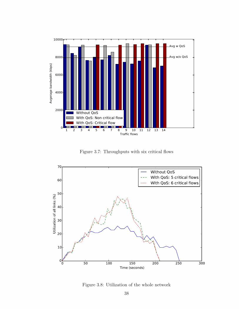
improved the throughput of other flows as shown in Figure 3.7.
The benefits of avoiding congested links include better utilization for network-
wide bandwidth. This is illustrated in Figure 3.8. Results were obtained from three
runs of the experiment, i.e., without the QoS module enabled, with the QoS module
enabled with 5 critical flows, and with the QoS module enabled with 6 critical flows.
It shows that when the QoS module was enabled, the network achieved higher levels
of utilization.
37
1 2 3 4 5 6 7 8 9 10 11 12 13 14Traffic flows
0
2000
4000
6000
8000
10000
Avge
rage
ban
dwid
th (k
bps)
Avg w QoS
Avg w/o QoS
Without QoSWith QoS: Non critical flowWith QoS: Critical flow
Figure 3.7: Throughputs with six critical flows
Figure 3.8: Utilization of the whole network
38

3.4.2 Second Experiment
Experiment Setup
In the previous experiment, the QoS routing module was able to find a feasible path
for all critical flows. Which means all critical flows were accepted by the module.
However, this is not always the case. Sometimes the network becomes congested in a
way that prevents finding a path with sufficient capacity. In the second experiment,
we want to measure the overall performance of the network in relation to the number
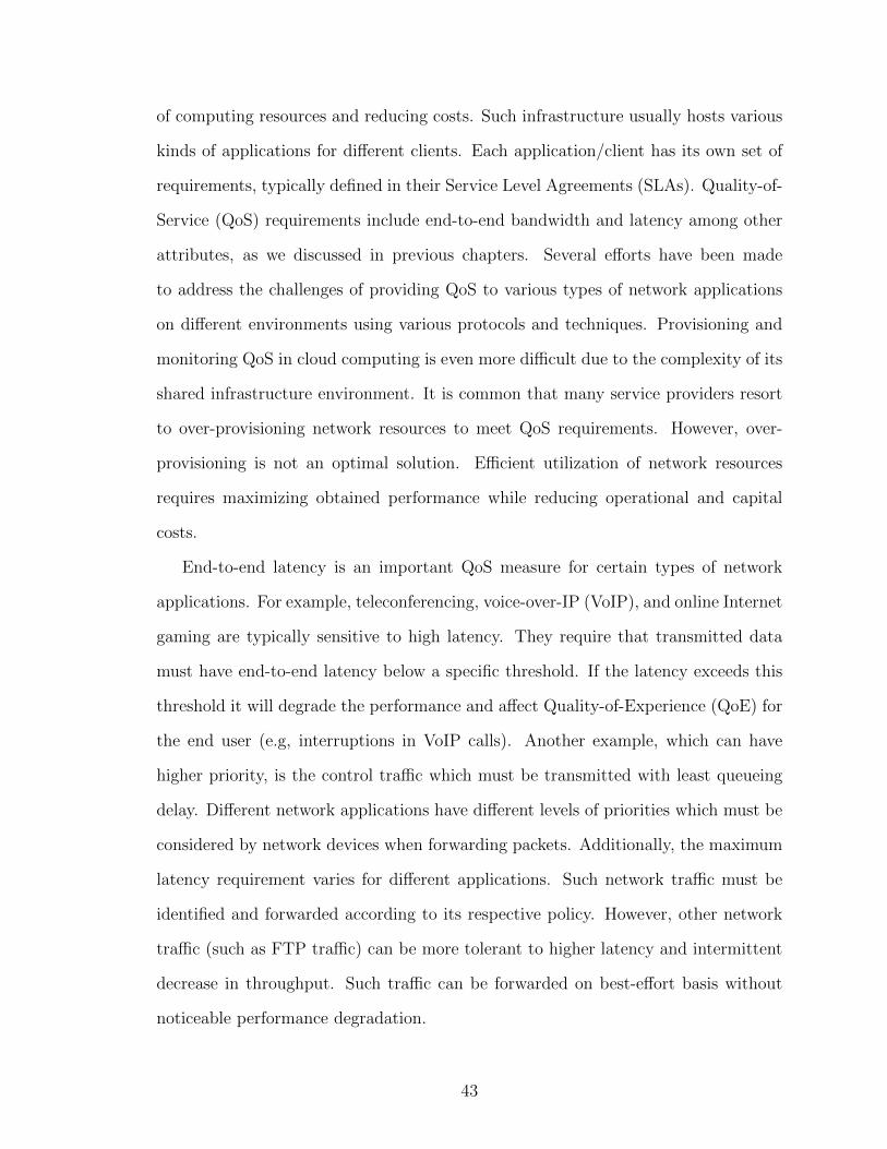
of accepted flows. We created a different topology of 5 switches and 20 hosts. Each
switch is connected to four hosts. The bandwidth of the links between switches is set
to 15 Mbps and the bandwidth of the links between switches and hosts is set to 10
Mbps. The topology is shown in Figure 3.9. We generated a random list of 20 traffic
flows such that:
• Each host will send and receive only one flow.
• Source and destination switches are different for each flow.
• Start time and duration are random (within a range).
• All flows are critical.
Results
This experiment was repeated 30 times, each time with a different list of flows. For
each time, we measured the total average throughput of all flows and the average
throughput of the accepted flows. Figure 3.10 shows the obtained results. We can
see clearly that as the number of accepted flows increase, the average throughput of
all flows increase. Moreover, the average throughput of accepted flows is more than
that of all flows.
39
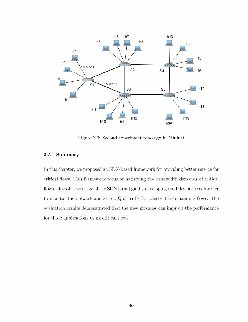
Figure 3.9: Second experiment topology in Mininet
3.5 Summary
In this chapter, we proposed an SDN-based framework for providing better service for
critical flows. This framework focus on satisfying the bandwidth demands of critical
flows. It took advantage of the SDN paradigm by developing modules in the controller
to monitor the network and set up QoS paths for bandwidth-demanding flows. The
evaluation results demonstrated that the new modules can improve the performance
for those applications using critical flows.
40

0 5 10 15 20Number of accepted critical flows
0
2000
4000
6000
8000
10000
Avgera
ge t
hro
ughput
(Kbps)
Avg throughput for all critical flowsAvg throughput for accepted critical flows
Figure 3.10: Average throughput to the number of accepted flows
41

Chapter 4
Provisioning Quality of Service to
Latency-Sensitive Traffic Flows
4.1 Overview
Modern computer networks accommodate heterogeneous applications that have
different levels of Quality-of-Service requirements. Some of network traffic flows
have tight deadlines where slight increases in latency can affect the overall
performance of the application. Such traffic flows need to be forwarded with higher
priority than other traffic. Planning and designing networked systems that are able
to efficiently provide latency guarantee remains a challenge. In this chapter, we
propose a system designed for provisioning QoS to latency-sensitive traffic flows
using the SDN approach. This system provides convenient mechanisms for defining,
managing, and forwarding different classes of traffic flows with different levels of
priorities.
4.1.1 Motivation
In recent years there has been an increasingly growing interest in cloud computing
and virtualized environments. This is motivated by the need for efficient utilization
42
of computing resources and reducing costs. Such infrastructure usually hosts various
kinds of applications for different clients. Each application/client has its own set of
requirements, typically defined in their Service Level Agreements (SLAs). Quality-of-
Service (QoS) requirements include end-to-end bandwidth and latency among other
attributes, as we discussed in previous chapters. Several efforts have been made
to address the challenges of providing QoS to various types of network applications
on different environments using various protocols and techniques. Provisioning and
monitoring QoS in cloud computing is even more difficult due to the complexity of its
shared infrastructure environment. It is common that many service providers resort
to over-provisioning network resources to meet QoS requirements. However, over-
provisioning is not an optimal solution. Efficient utilization of network resources
requires maximizing obtained performance while reducing operational and capital
costs.
End-to-end latency is an important QoS measure for certain types of network
applications. For example, teleconferencing, voice-over-IP (VoIP), and online Internet
gaming are typically sensitive to high latency. They require that transmitted data
must have end-to-end latency below a specific threshold. If the latency exceeds this
threshold it will degrade the performance and affect Quality-of-Experience (QoE) for
the end user (e.g, interruptions in VoIP calls). Another example, which can have
higher priority, is the control traffic which must be transmitted with least queueing
delay. Different network applications have different levels of priorities which must be
considered by network devices when forwarding packets. Additionally, the maximum
latency requirement varies for different applications. Such network traffic must be
identified and forwarded according to its respective policy. However, other network
traffic (such as FTP traffic) can be more tolerant to higher latency and intermittent
decrease in throughput. Such traffic can be forwarded on best-effort basis without
noticeable performance degradation.
43

QoS requirements for latency-sensitive traffic differ depending on the application
type. The ITU-T 1 recommends that in general network planning, a maximum of
400 ms for one-way latency should not be exceeded [1]. However, they note that
many interactive applications (e.g, voice calls, video conferencing, interactive data
applications) are affected by much lower latency. The experiences of most applications
are generally considered acceptable if the latency is kept below 150 ms. As the
traffic latency increases, the impact on applications’ experiences becomes noticeable.
When the latency exceeds 400 ms, most applications will encounter unsatisfactory
performance.
Figure 4.1: Effects of the total delay on user satisfication (reprinted from [1])
1The ITU-T is the Telecommunication Standardization Sector of the InternationalTelecommunication Union (ITU) which develops international standards for telecommunications.(https://www.itu.int/)
44
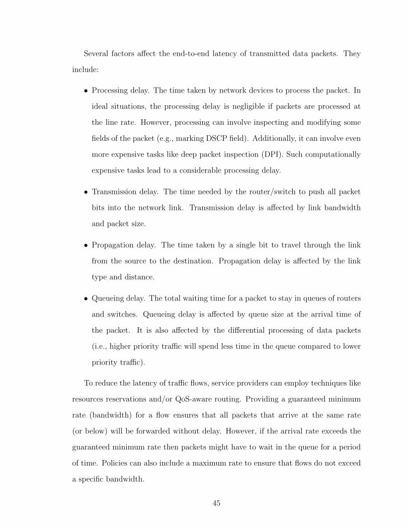
Several factors affect the end-to-end latency of transmitted data packets. They
include:
• Processing delay. The time taken by network devices to process the packet. In
ideal situations, the processing delay is negligible if packets are processed at
the line rate. However, processing can involve inspecting and modifying some
fields of the packet (e.g., marking DSCP field). Additionally, it can involve even
more expensive tasks like deep packet inspection (DPI). Such computationally
expensive tasks lead to a considerable processing delay.
• Transmission delay. The time needed by the router/switch to push all packet
bits into the network link. Transmission delay is affected by link bandwidth
and packet size.
• Propagation delay. The time taken by a single bit to travel through the link
from the source to the destination. Propagation delay is affected by the link
type and distance.
• Queueing delay. The total waiting time for a packet to stay in queues of routers
and switches. Queueing delay is affected by queue size at the arrival time of
the packet. It is also affected by the differential processing of data packets
(i.e., higher priority traffic will spend less time in the queue compared to lower
priority traffic).
To reduce the latency of traffic flows, service providers can employ techniques like
resources reservations and/or QoS-aware routing. Providing a guaranteed minimum
rate (bandwidth) for a flow ensures that all packets that arrive at the same rate
(or below) will be forwarded without delay. However, if the arrival rate exceeds the
guaranteed minimum rate then packets might have to wait in the queue for a period
of time. Policies can also include a maximum rate to ensure that flows do not exceed
a specific bandwidth.
45

We note that most traffic patterns are bursty in nature. For example, an HTTP
session starts with downloading HTML page and associated multimedia objects (e.g.,
style sheets, images, etc.) then it becomes idle for a period of time until the user
requests another HTML page. The inconsistency in traffic levels is very common
even among established long-running TCP connections. The reason is because TCP
congestion control adjusts the sending rate based on congestion signals to adapt to the
current network conditions. It follows the mechanism additive-increase multiplicative-
decrease (AIMD) which aims to preserve TCP friendliness and fairness to other traffic
flows. From this perspective, we can see that if such traffic flows were assigned a
guaranteed bandwidth (quota) then it is highly likely that there will be unused spare
bandwidth from this quota at a given point in time.
Latency-sensitive traffic patterns can be also bursty. We direct our attention
to traffic flows that do not constitute a significant portion of the total traffic in the
network. Such traffic flows are not transmitted with a consistent high rate all the time.
Therefore, their guaranteed minimum bandwidth (if reserved) is not used during their
idle time. However, when such traffic flows are transmitted they are not tolerant of
high latency. They need to be forwarded with higher priority on paths that guarantee
a maximum latency less than or equal to their specified latency requirement. From
this point, we realize the importance of managing priorities, guaranteed minimum
rate, maximum rate, and utilizing the unused guaranteed rate for different classes of
network traffic flows.
In this chapter, we propose a technique that is designed to provision and
monitor quality of service to latency-sensitive traffic flows using an SDN approach.
The system provides convenient mechanisms for defining and managing traffic
classes in the control plane. Each class has two properties:
• Defining characteristics: which contain a unique class name and a list of all
flows belonging to this class. Each flow is represented with a set of OpenFlow
46

match rules.
• QoS attributes: which contain class priority and optionally the minimum rate,
the maximum rate, and required latency.
4.1.2 Latency Measurements in SDN
Measuring latency in SDN has been discussed in the literature. For example,
OpenNetMon [31] injects probe packets into the source switch of each link and
install rules that make them traverse the link to be measured. The destination
switch is configured to send probe packets back to the control plane. The process
involves also estimating the latency between the controller and each switch by
injecting packets that are returned back immediately to the controller which uses
the round-trip time (RTT) to determine the latency. The monitoring application in
the controller calculates the estimated latency of each monitored link. The link
latency is calculated by subtracting the estimated controller-to-switches latencies
from the difference between departure time and arrival time.
Latency = TimeArrival − TimeSent −1
2(RTTsource +RTTdestination)
Floodlight [24], a popular SDN controller, uses a similar mechanism to calculate
an estimated latency value for each link in the topology. The link discovery module
encapsulates timestamps with LLDP packets using the optional type-length-value
(TLV) structure. It periodically sends LLDP packets through all available ports. The
link latency is smoothed by calculating the average of a specific number of latency
measurements. The calculated latency is stored as attribute for each link in the
discovered topology.
47

4.1.3 Queueing Disciplines
Queueing discipline (also known as qdisc) controls how packets are processed while
waiting in the queue. The type of queueing discipline has direct influence on the
latency as it determines how long the packet will have to wait before being served
(transmitted). We limit our discussion to queueing disciplines that are available in
Linux. The simplest type of queueing discipline is the first-in first-out (FIFO)
qdisc. It ensures that the first packet to arrive will be transmitted before
subsequent packets regardless of any other considerations. Although FIFO qdisc
provides a straightforward and fast implementation, it does not enable any
differential treatment for data packets. Therefore, it is not suitable for provisioning
QoS. Additionally, using FIFO qdisc does not provide fair service to multiple traffic
flows. This is because some large flows can fill the queue buffer quickly which will
cause packets dropping of other flows. This unfair service pattern triggered the need
for different queueing disciplines that provide fair service to multiple flows.
The stochastic fair queuing (SFQ) qdisc is an implementation of fair queueing [32].
It aims to serve all traffic flows equally by creating several queues and then, using
hashing, maps packets to queues. A level of fairness is achieved by transmitting from
each queue in a round-robin manner. Both FIFO and SFQ are classless queueing
disciplines. That is, it is not possible to provide different service for different classes
of traffic flows.
The hierarchical token bucket (HTB) [33] is a classful qdisc that was proposed
to replace a previous classful queueing discipline called class-based queueing (CBQ)
qdisc in Linux systems. HTB allows arranging different classes of traffic flows into
a hierarchical structure. While HTB is mostly used for bandwidth guarantee, our
SDN-based system utilizes it for latency-sensitive QoS provisioning. Queues can be
configured by Linux tc command. The software switch Open vSwitch [22] provides
support for HTB qdisc, although it does not cover all its features. Open vSwitch
48

allows configuring HTB queues either by command line interface (CLI) or by OVSDB
protocol. We will discuss HTB qdisc in the next sections.
The hierarchical fair-service curve (HFSC) [34] is another classful qdisc available
in Linux. HFSC also provides the ability to create a hierarchical structure of different
traffic classes. HFSC aims to provide guaranteed service for both bandwidth and
delay parameters by maintaining a service curve for each parameter. Open vSwitch
allows creating queues based on HFSC qdisc. However, the delay parameter is not
supported by Open vSwitch.
4.2 Related Work
Wallner and Cannistra [35] proposed a method for providing QoS in SDN. It involves
using traffic shaping (rate limiting). Network traffic is classified using Differentiated
Services Code Point (DSCP) value in the DiffServ field in the IP header. The QoS
module (implemented in Floodlight) manages classes of traffic and their associated
DSCP values. It handles QoS policies and manipulates flow tables. Based on traffic
class, the module uses enqueue action in OpenFlow 1.0 to forward traffic using the
pre-configured queues in Open vSwitch. The benefits of this solution are limited since
it requires having all queues set up on switches in advance and does not implement
dynamic routing.
QueuePusher [36] is a queue management extension for SDN controller that allows
applications to manipulate queues in Open vSwitch nodes. It is implemented as a
module for Floodlight controller. The QueuePusher module exposes basic queues
operations (create, read, update, and delete) to other programs through northbound
REST APIs. These basic operations can be used as basis for creating SDN-based
QoS applications.
Capa and Soler [37] proposed a similar QoS configuration module for Floodlight
controller. They implemented a subset of OVSDB protocol to manage queues in
49

Open vSwitch. Their APIs can be consumed by other internal Floodlight modules
using JAVA or by external applications using REST APIs.
4.3 An SDN-based Architecture for Supporting Latency-Sensitive Flows
In this section, we present our proposed approach for provisioning QoS to latency-
sensitive traffic. The proposed system focuses on accommodating different classes
of traffic flows. It makes use of SDN architecture and HTB queueing discipline. In
our approach, latency-sensitive flows are grouped into classes. Each class contains
information that specify how its flows are forwarded.
The SDN-based system consists of the following components:
• Admission control module: responsible for handling new QoS requests.
Depending on the nature of the requirements and the available resources, new
requests are either accepted or rejected.
• QoS provisioning module: responsible for configuring queues and installing
OpenFlow rules to provide the required service for accepted QoS requests.
• QoS monitoring module: retrieves and presents statistics about active QoS
classes.
• OVSDB agent module: translates queue setup commands into OVSDB
protocol messages.
4.3.1 Admission Control
The admission control is responsible for handling new QoS requests. It is accessible
through REST APIs for authorized applications. Additionally, system administrators
can access a web interface for adding new requests. The new request is expected to
specify the priority of the traffic class. Priority is expressed as an integer value
50
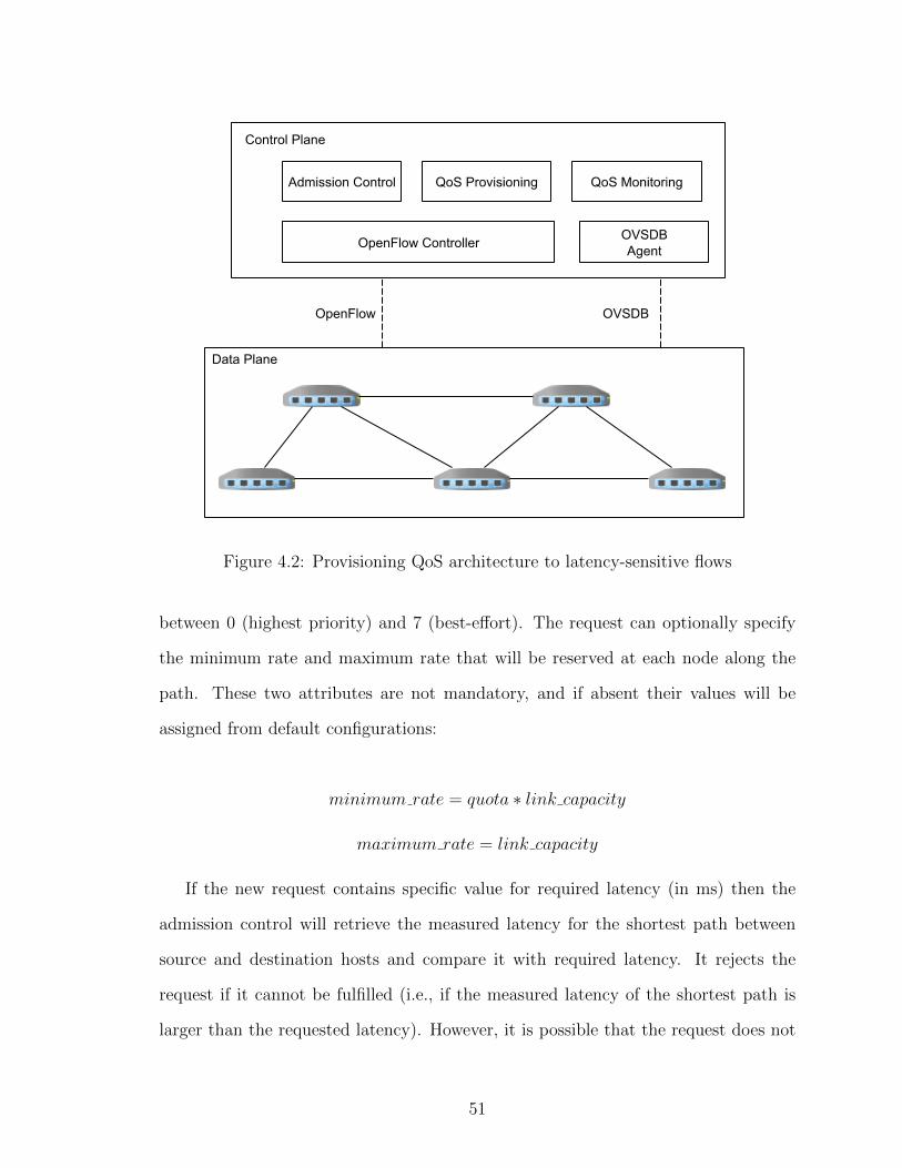
Figure 4.2: Provisioning QoS architecture to latency-sensitive flows
between 0 (highest priority) and 7 (best-effort). The request can optionally specify
the minimum rate and maximum rate that will be reserved at each node along the
path. These two attributes are not mandatory, and if absent their values will be
assigned from default configurations:
minimum rate = quota ∗ link capacity
maximum rate = link capacity
If the new request contains specific value for required latency (in ms) then the
admission control will retrieve the measured latency for the shortest path between
source and destination hosts and compare it with required latency. It rejects the
request if it cannot be fulfilled (i.e., if the measured latency of the shortest path is
larger than the requested latency). However, it is possible that the request does not
51
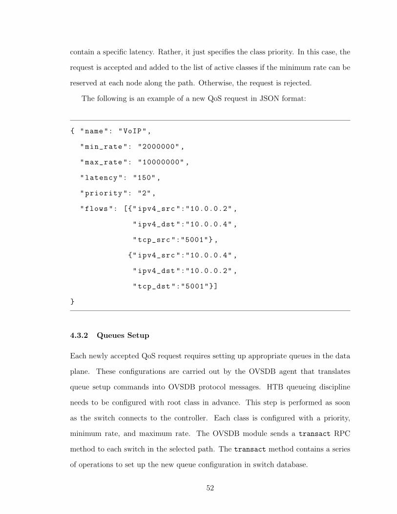
contain a specific latency. Rather, it just specifies the class priority. In this case, the
request is accepted and added to the list of active classes if the minimum rate can be
reserved at each node along the path. Otherwise, the request is rejected.
The following is an example of a new QoS request in JSON format:
{ "name": "VoIP",
"min_rate ": "2000000" ,
"max_rate ": "10000000" ,
"latency ": "150",
"priority ": "2",
"flows ": [{" ipv4_src ":"10.0.0.2" ,
"ipv4_dst ":"10.0.0.4" ,
"tcp_src ":"5001"} ,
{" ipv4_src ":"10.0.0.4" ,
"ipv4_dst ":"10.0.0.2" ,
"tcp_dst ":"5001"}]
}
4.3.2 Queues Setup
Each newly accepted QoS request requires setting up appropriate queues in the data
plane. These configurations are carried out by the OVSDB agent that translates
queue setup commands into OVSDB protocol messages. HTB queueing discipline
needs to be configured with root class in advance. This step is performed as soon
as the switch connects to the controller. Each class is configured with a priority,
minimum rate, and maximum rate. The OVSDB module sends a transact RPC
method to each switch in the selected path. The transact method contains a series
of operations to set up the new queue configuration in switch database.
52

4.3.3 Installing OpenFlow Rules
After queues are configured using OVSDB agent, the QoS provisioning module will
install OpenFlow rules at each switch along the path (or paths) for all traffic flows
that belong to this class. The installed OpenFlow rules match each traffic flow and
direct its packets to the queue ID configured for the class. This module consumes the
controller northbound APIs.
4.3.4 Monitoring and Reporting
Monitoring is an important task that complements the installation and configuration
of QoS. The module retrieves statistics from data plane switches periodically. It
presents them to system administrators and authorized applications using REST
APIs. Each report of queue statistics include:
• The number of transmitted bytes.
• The number of transmitted packets.
• The number of dropped packets.
4.4 Provisioning QoS to Latency-Sensitive Flows
The HTB qdisc allows arranging traffic classes in a multi-layered hierarchical tree.
In our system, we use two layers where the root node (in the first layer) represents
the parent class for all kinds of traffic. The root node is configured as soon as a
switch connects to the controller. The maximum rate and minimum rate for the root
class are both equal to the link speed. For each accepted QoS request, the admission
control creates a leaf node linked to the root node with the properties specified in the
request. The two main properties are the minimum rate and priority. Typically, the
maximum rate for the class is equal to the root (link speed) unless explicitly stated
otherwise in the request.
53

The minimum rate is the guaranteed bandwidth given to the class. However, it
is possible for a class to exceed this limit up to its maximum rate (or ceil). This
happens when it is possible for the leaf node to borrow tokens (i.e., consume unused
bandwidth) from its parent class. At any point in time, the leaf node can have one
of three states:
• Throughput reached max-rate. It cannot send packets nor borrow tokens
from its parent. Packets of the class will remain in the queue until tokens
become available.
• Throughput reached min-rate. It can try to borrow tokens from its parent.
If tokens are available then packets will be transmitted in a number matching
the available tokens. Otherwise, packets will remain in the queue until tokens
become available.
• Throughput is less than min-rate. It can send packets as long as there are
enough tokens.
Tokens are added to the class bucket in the specified minimum rate until the
bucket size is reached. Packets belonging to a class are sent only if its corresponding
bucket have available tokens. Otherwise, packets will have to wait in the class queue
until new tokens become available. By default, FIFO queue is attached to each leaf
class. Arriving packets are dropped if their class queue is full. Increasing the size of
the queue buffer reduces the packet loss ratio. However, large buffer size can lead to
an increased latency for lower priority traffic.
For each packet sent, a token is withdrawn from its bucket (for simplicity, we
assume one token represents one packet). If the class bucket is empty and the class
queue has packets, it tries to borrow tokens from the parent class. When multiple
classes try to borrow from the same parent, the classes with highest priority are
served first. If two or more classes have the same priority, the spare bandwidth is
54

split between them. Priority is represented as a number between 0 and 7 where 0 is
the highest priority. The leaf class is allowed to borrow and consume tokens until its
maximum rate is reached.
Figure 4.3: Example of different traffic classes
While OpenFlow protocol can be used to install rules that utilize existing queues,
it cannot be used for creating new queues. Switch configurations, which includes
queues among other attributes, are defined outside the scope of OpenFlow. Using
command-line-interface (CLI) of the switch is not a convenient method, specially
for dynamic configuration of a large number of switches. There are two protocols
proposed for switch configuration. The OpenFlow Management and Configuration
Protocol (OF-CONFIG) [38] and the Open vSwitch Database Management Protocol
(OVSDB) [39]. We chose to implement OVSDB protocol because it is fully supported
by OpenvSwitch.
OVSDB itself is based on JSON-RPC protocol version 1.0 [40]. Switch
configuration are stored in a database with defined schema [41]. Manipulating this
database, using OVSDB, allows applications to dynamically manage the switch and
55
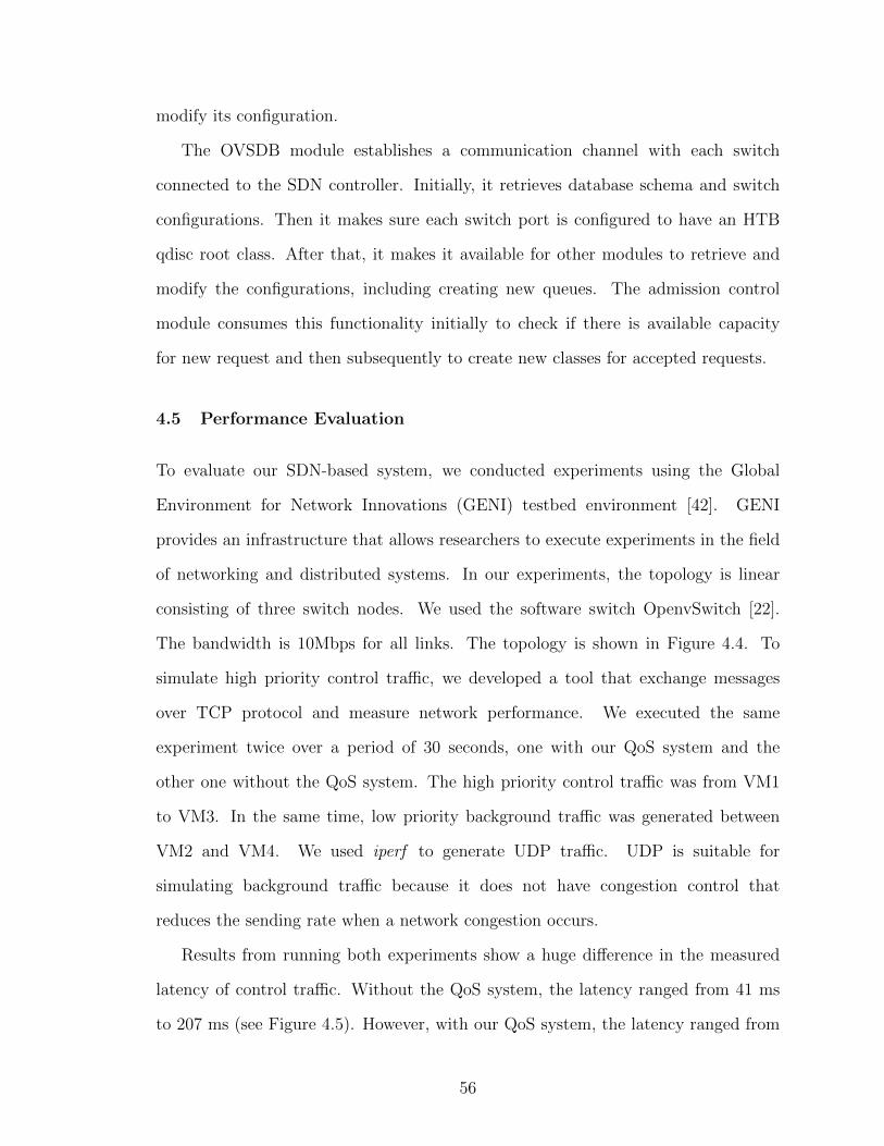
modify its configuration.
The OVSDB module establishes a communication channel with each switch
connected to the SDN controller. Initially, it retrieves database schema and switch
configurations. Then it makes sure each switch port is configured to have an HTB
qdisc root class. After that, it makes it available for other modules to retrieve and
modify the configurations, including creating new queues. The admission control
module consumes this functionality initially to check if there is available capacity
for new request and then subsequently to create new classes for accepted requests.
4.5 Performance Evaluation
To evaluate our SDN-based system, we conducted experiments using the Global
Environment for Network Innovations (GENI) testbed environment [42]. GENI
provides an infrastructure that allows researchers to execute experiments in the field
of networking and distributed systems. In our experiments, the topology is linear
consisting of three switch nodes. We used the software switch OpenvSwitch [22].
The bandwidth is 10Mbps for all links. The topology is shown in Figure 4.4. To
simulate high priority control traffic, we developed a tool that exchange messages
over TCP protocol and measure network performance. We executed the same
experiment twice over a period of 30 seconds, one with our QoS system and the
other one without the QoS system. The high priority control traffic was from VM1
to VM3. In the same time, low priority background traffic was generated between
VM2 and VM4. We used iperf to generate UDP traffic. UDP is suitable for
simulating background traffic because it does not have congestion control that
reduces the sending rate when a network congestion occurs.
Results from running both experiments show a huge difference in the measured
latency of control traffic. Without the QoS system, the latency ranged from 41 ms
to 207 ms (see Figure 4.5). However, with our QoS system, the latency ranged from
56

Figure 4.4: Experiment topology
Figure 4.5: Measured latency of control traffic messages
3.9 ms to 5.1 ms.
The same experiment was repeated with TCP background traffic. Results show
that there was no significant impact on the latency of control traffic even without
running QoS module. The reason is because the congestion control algorithm for
TCP reduces the sending rate when it detects a congestion in the network maintaining
what is called TCP friendliness. Additionally, we were sending a single TCP flow on
57

the same path. This result shows the huge difference between the two transport
protocols.
4.6 Summary
In this chapter, we proposed a system to address the challenge of providing QoS to
latency-sensitive traffic. Queueing delay constitutes a significant part of the total
delay of transmitted packets. Using SDN, the proposed system dynamically
allocates queues for different classes of traffic. It accommodates classes of different
priorities and attributes. Evaluation results show that latency of high priority traffic
is minimized even with the existence of UDP background traffic that saturates the
network path.
58

Chapter 5
Improving Throughput of Large
Flows Using Multipath TCP
5.1 Overview
The recent developments in data center topologies offer high bandwidth capacity
and multiple paths between processing nodes. The increased use of cloud computing
applications imposes challenges on underlying network infrastructure. To meet these
challenges we need efficient traffic management that can maximize the utilization of
multi-path data center networks. Path diversity not only provides the opportunity
of performing load balancing and improves fault tolerance, but also can be exploited
to allocate more bandwidth for large flows and improve the performance of network-
limited applications.
In this chapter, we present an architecture based on Multipath TCP and Software
Defined Networking to provide better bandwidth allocation for large flows. The SDN
controller, which has global knowledge of network topology and traffic measurements,
is capable of making educated routing decisions. The proposed SDN architecture
enables applications to achieve better throughput for large flows by initiating new
MPTCP subflows. To provide this capability, we modify the MPTCP implementation
59
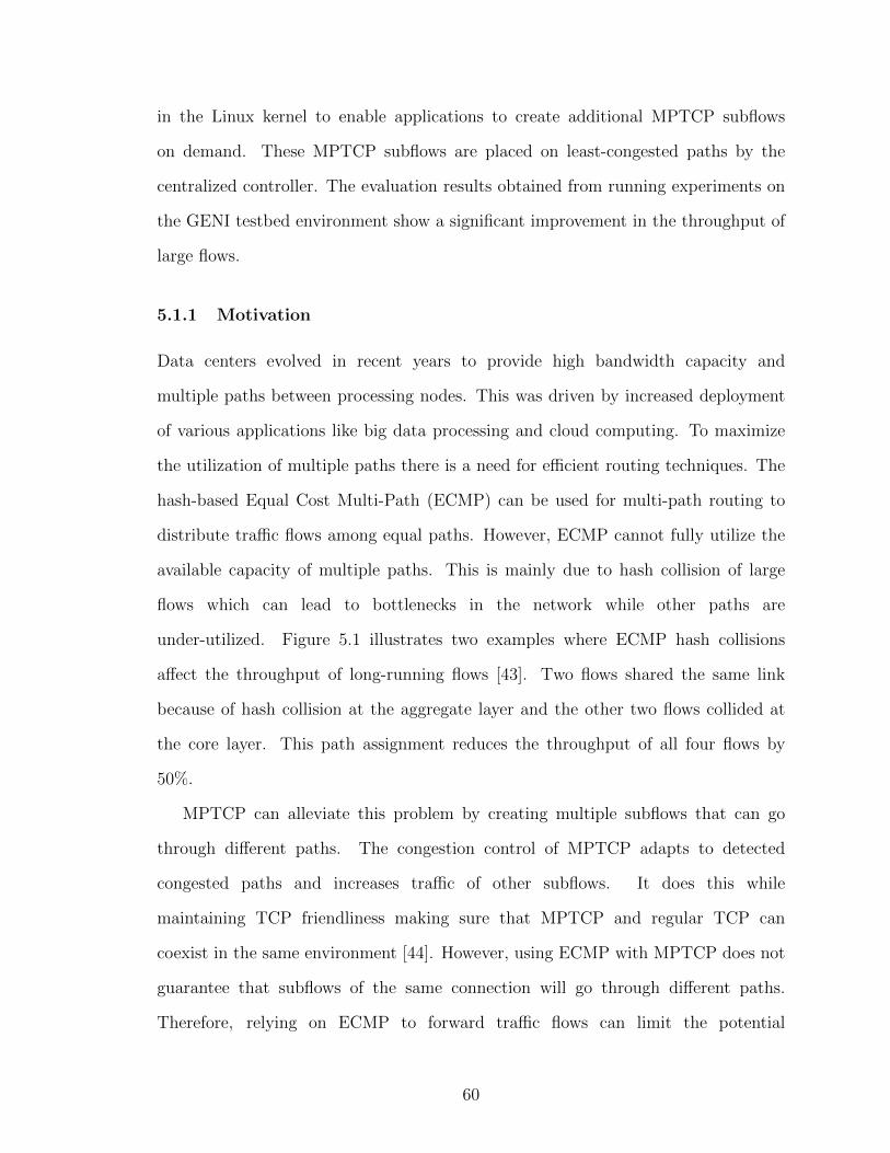
in the Linux kernel to enable applications to create additional MPTCP subflows
on demand. These MPTCP subflows are placed on least-congested paths by the
centralized controller. The evaluation results obtained from running experiments on
the GENI testbed environment show a significant improvement in the throughput of
large flows.
5.1.1 Motivation
Data centers evolved in recent years to provide high bandwidth capacity and
multiple paths between processing nodes. This was driven by increased deployment
of various applications like big data processing and cloud computing. To maximize
the utilization of multiple paths there is a need for efficient routing techniques. The
hash-based Equal Cost Multi-Path (ECMP) can be used for multi-path routing to
distribute traffic flows among equal paths. However, ECMP cannot fully utilize the
available capacity of multiple paths. This is mainly due to hash collision of large
flows which can lead to bottlenecks in the network while other paths are
under-utilized. Figure 5.1 illustrates two examples where ECMP hash collisions
affect the throughput of long-running flows [43]. Two flows shared the same link
because of hash collision at the aggregate layer and the other two flows collided at
the core layer. This path assignment reduces the throughput of all four flows by
50%.
MPTCP can alleviate this problem by creating multiple subflows that can go
through different paths. The congestion control of MPTCP adapts to detected
congested paths and increases traffic of other subflows. It does this while
maintaining TCP friendliness making sure that MPTCP and regular TCP can
coexist in the same environment [44]. However, using ECMP with MPTCP does not
guarantee that subflows of the same connection will go through different paths.
Therefore, relying on ECMP to forward traffic flows can limit the potential
60
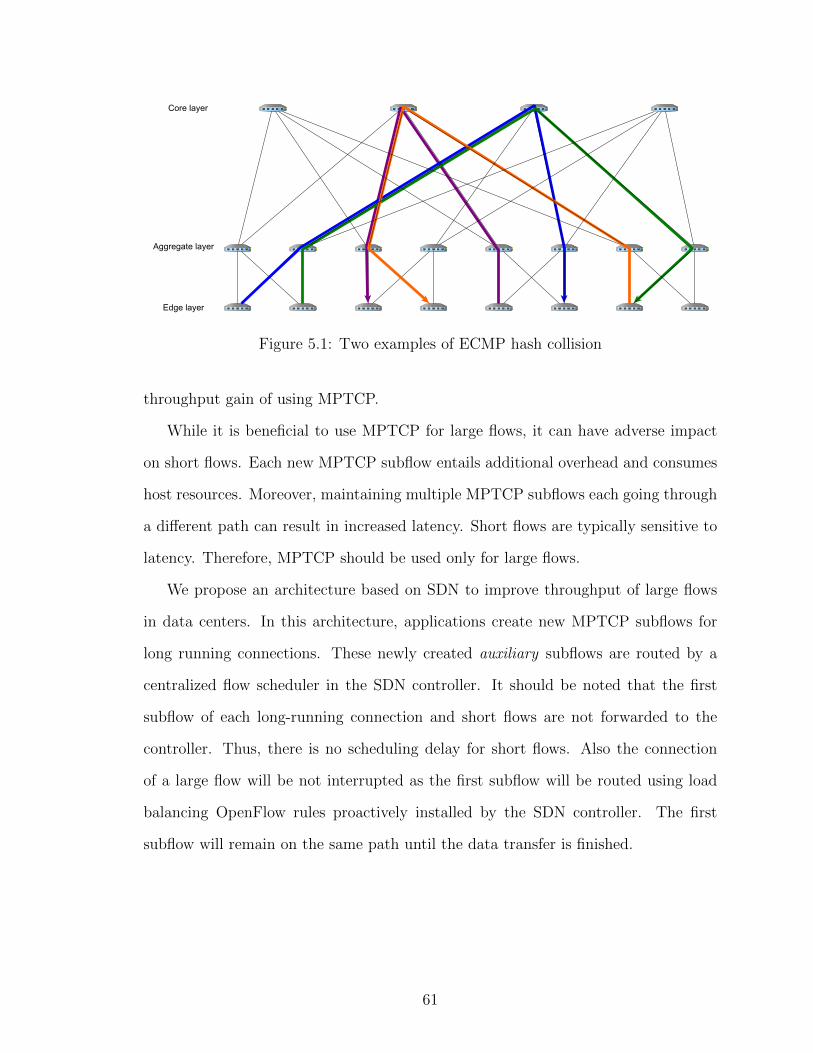
Figure 5.1: Two examples of ECMP hash collision
throughput gain of using MPTCP.
While it is beneficial to use MPTCP for large flows, it can have adverse impact
on short flows. Each new MPTCP subflow entails additional overhead and consumes
host resources. Moreover, maintaining multiple MPTCP subflows each going through
a different path can result in increased latency. Short flows are typically sensitive to
latency. Therefore, MPTCP should be used only for large flows.
We propose an architecture based on SDN to improve throughput of large flows
in data centers. In this architecture, applications create new MPTCP subflows for
long running connections. These newly created auxiliary subflows are routed by a
centralized flow scheduler in the SDN controller. It should be noted that the first
subflow of each long-running connection and short flows are not forwarded to the
controller. Thus, there is no scheduling delay for short flows. Also the connection
of a large flow will be not interrupted as the first subflow will be routed using load
balancing OpenFlow rules proactively installed by the SDN controller. The first
subflow will remain on the same path until the data transfer is finished.
61

5.1.2 Data Center Topologies
The design of data center networks focused recently on using cheaper commodity
hardware rather than expensive high-end routers and switches. The motivation of
this trend is to build more cost-efficient networks that meet current computing
requirements. Several designs address issues like bottlenecks and limited bisection
bandwidth of traditional data center networks by inter-connecting multiple
commodity switches.
The k-ary Fat Tree topology [45] is a Clos [46] topology that arranges k-port
switches in a multi-rooted tree structure. The core layer has (k/2)2 switches connected
to k pods. Each pod contains k/2 aggregation layer switches and k/2 edge layer
switches. The topology supports (k3)/4 hosts. Figure 5.9 shows this topology where
k = 6. Other designs include BCube [47], Jellyfish [48], and VL2 [49].
These topologies bring new traffic engineering challenges to data centers. SDN
architecture can play a significant role in solving these challenges. Controller
applications are capable of monitoring the changing traffic conditions and pushing
OpenFlow rules to adapt to the current traffic requirements.
5.2 Multipath TCP
Multipath TCP is an extension to regular TCP protocol that provides the ability for
a single TCP connection to operate on multiple paths [50]. This extension does not
require any modification to the application layer as the transport layer transparently
handles the multiple connections, called subflows, which appear as a single connection
to the application. It is also transparent to the network layer as each subflow appears
as a normal TCP connection. Figure 5.2 depicts MPTCP and TCP in the protocol
stack. Each MPTCP subflow can go through a different path in the network, or
even a different network interface if the host has multiple network interfaces (multi-
homed host). The MPTCP extension provides more resilience to TCP protocol as
62

the connection will not be interrupted if one link goes down as long as there exists
at least one connected subflow. Another benefit is providing applications with more
bandwidth by aggregating multiple paths.
Figure 5.2: TCP and MPTCP protocol
One of the key design features of MPTCP is the fallback to regular TCP if
MPTCP is not supported by either host or any middlebox. A new TCP option kind
is introduced to indicate that the TCP connection supports MPTCP. This option
kind has the decimal value 30. The TCP option also contains MPTCP subtype
which is used to signal MPTCP operations (e.g., MP JOIN is used by new subflows
to request joining an existing MPTCP connection). Table 5.1 lists MPTCP option
subtypes [50].
Table 5.1: Multipath TCP Option subtypes
Symbol Value Name
MP CAPABLE 0x0 Multipath capable
MP JOIN 0x1 Join connection
DSS 0x2 Data sequence signal
ADD ADDR 0x3 Add address
REMOVE ADDR 0x4 Remove address
MP PRIO 0x5 Change subflow priority
MP FAIL 0x6 Fallback
MP FASTCLOSE 0x7 Fast close
63

A Multipath TCP session starts in the similar way to a regular TCP session.
The difference is that SYN, SYN/ACK, and ACK packets carry the MPTCP option
kind (30) with MP CAPABLE option subtype. MP CAPABLE option subtype is
used by the first subflow of MPTCP connection to indicate that the sending host
supports MPTCP. If the sending host receives a SYN/ACK without MP CAPABLE it
assumes that the other host does not support MPTCP. The other possibility, although
highly unlikely, is when a legacy middlebox modify TCP options because it was
configured to remove unrecognized TCP options. In this case, the connection falls
back to regular TCP and the two hosts continue to exchange packets through a single
TCP flow. If both hosts completed the three-way handshake with MP CAPABLE,
then they have established a Multipath TCP connection and either one can initiate
additional subflows. During the initial three-way handshake, the two hosts exchange
keys used to associate subsequent subflows with this connection. The keys are unique
for each connection. Figure 5.3 illustrates the process of establishing a Multipath
TCP connection using MP CAPABLE and then adding one additional subflow using
MP JOIN.
The keys exchanged in MP CAPABLE handshake are used to generate
cryptographic hashes called tokens. After that, the keys are not sent over the
network. Instead, the cryptographic hash of the key, or token, is used to identify the
connection. Tokens are used in MP JOIN to associate the subflow with existing
MPTCP connection. The purpose of using tokens is to make sure that the new
subflow will join the correct MPTCP connection. The Hash-based Message
Authentication Code (HMAC) generated from the key and nonce (random number)
is used for authenticating the other host.
New MPTCP subflows do not need to be between different IP pairs. It is possible
to have multiple subflows from the same IP pair given that they operate on different
TCP ports. Typically, this is beneficial where ECMP is used to forward traffic flows,
64

Figure 5.3: MPTCP subflows initiation
as these subflows can have different paths which will lead to increased throughput for
the application. However, as we discussed earlier, ECMP employs hashing and there
is no guarantee that multiple subflows of the same connection will end up in disjoint
paths.
5.2.1 Congestion Control
In regular TCP, the congestion control plays a pivotal role in avoiding congestion
collapse in network. TCP maintains what is called congestion window to keep the
transmission rate below the level that can cause network congestion. It basically limits
the number of unacknowledged data at the source host. The size of the congestion
window is changed throughout the connection lifetime to adapt to detected congestion
signals. The destination host normally sends an acknowledgement (ACK) to the
65

source host for each received packet. The source host infers that a packet loss has
occurred when it does not receive an ACK before a timeout. TCP calculates this
timeout, called retransmission timeout (RTO), based on smoothed value of estimated
round-trip time (RTT) between source and destination hosts [51]. In addition to
RTO, the duplicate acknowledgements (DupACK) are considered a congestion signal.
When the host receives an out of order packet it sends an ACK for the last in-order
packet it had received so far. Sending a DupACK means that the receiver is still
expecting the next packet. However, since a packet can get delayed or reordered
while in transit, three DupACKs are needed to detect a packet loss.
TCP adjustments for the congestion window follow the approach of additive
increase/multiplicative decrease (AIMD). That means TCP will increase the
transmission rate by adding a value to the congestion window when it receives a
new ACK, and will decrease the transmission rate by a multiplicative factor (e.g.,
divide by 2) when a packet loss is detected. This conservative behavior is essential
in avoiding network congestion. We will leave out the discussion of different TCP
implementations (e.g., Tahoe , Reno, New Reno, etc.) and the other TCP schemes
slow-start, fast retransmit, and fast recovery as they are beyond the scope of this
research.
In MPTCP, the role of congestion control expands to include issues that do not
exist in single path TCP. The main issues are fairness to regular TCP and shifting
traffic from congested paths to other paths that have less traffic. To explain the
issue of fairness, consider that each MPTCP subflow behave like regular TCP. If a
single TCP connection shares a bottleneck with only one MPTCP connection that
has two subflows, this will result in the TCP flow getting half the throughput of
MPTCP connection. This mechanism is known as uncoupled congestion control. In
this mechanism, each MPTCP subflow s maintains its own congestion windows Ws
and the AIMD behavior is as follows:
66

• Each ACK on subflow s will increase the window Ws by 1/Ws.
• Each detected loss of subflow s will decrease Ws by Ws/2.
The aggregated throughput of the MPTCP connection is excessively large.
However, this gain can be on the expense of competing TCP flows on shared
bottlenecks. This behavior is too aggressive against single flow TCP and violates
the design principle “do no harm”. In order for a new protocol to be adopted, it has
to be fair to existing protocols. Therefore, MPTCP subflows should not behave like
regular TCP flows.
The coupled congestion control tries to solve this problem by changing AIMD
parameters. In the coupled congestion control, each MPTCP connection maintains
a congestion window Wtotal which is equal to the sum of all Ws maintained by its
subflows. The Ws is bound to be ≥ 1 . The AIMD behavior is as follows:
• Each ACK on subflow s will increase the window Ws by 1/Wtotal.
• Each detected loss of subflow s will decrease Ws by Wtotal/2.
The coupled congestion control achieves the goal of fairness to regular TCP by
taking into account the total congestion window of all subflows. In addition to that, it
balances traffic between subflows based on encountered congestion signals. By shifting
traffic from subflows on congested links to other subflows on least-congested paths, the
throughput of other flows on congested bottlenecks will increase. Consequently, the
overall network will achieve better resource utilization and load balancing. However,
coupled congestion control have drawbacks that have been discussed in [44]. First,
it favors the paths with less packet loss ratio regardless of their RTT values. Some
routers are configured with large buffers to reduce packet drops which in the same
time can lead to increasing RTT. However, smaller RTT value will result in higher
throughput. The second issue is that because traffic can be shifted entirely from
67

congested paths, there is no way to indicate that such paths are available when they
become less congested. It becomes clear that there need to be sufficient traffic on
each subflow to probe the paths regardless of how congested they are.
The linked increases algorithm (LIA) [52] was proposed to address the drawbacks
of coupled congestion control. LIA aims to achieve the following goals:
1. Improving throughput: MPTCP connection should achieve throughput equal
to or greater than what a single TCP flow would have achieved on the best
path available to MPTCP.
2. Not harming: MPTCP subflows of the same connection sharing a network
resource should not take more capacity than a single flow would have on the
same path.
3. Balancing congestion: MPTCP connection should shift traffic from
most-congested paths to least-congested paths as much as possible.
The AIMD behavior in LIA is as follows:
• Each ACK on subflow s will increase the window Ws by:
min(α ∗ bytes acked ∗MSSs
Wtotal
,bytes acked ∗MSSs
Ws
)
The minimum increment value is 1. MSSs is the maximum segment size for
subflow s.
• Each detected loss of subflow s will decrease Ws by Ws/2.
α is a parameter that controls the aggressiveness of MPTCP. It is calculated based
on the estimated RTT as follows:
α = Wtotal
maxs(Ws
(RTTs)2)
(∑
s(Ws
RTTs))2
68

The combined throughput for an MPTCP connection in LIA depends on the
values of α, the packet loss ratio, RTT and MSS for each of its subflows. LIA is part
of Linux kernel implementation of MPTCP. We used this congestion control in our
demonstration because it provides better throughput gain while not harming regular
TCP flows. Additionally, shifting traffic between subflows depending on congestion
signals is important to achieve adaptive load balancing.
5.3 Related Work
There has been a significant number of research efforts for improving the performance
of data center networks. The issue of routing large flows was of particular interest
to many proposals. Hedera [43] detects large flows from continuous monitoring of
network measurements by the SDN controller. Traffic flows are initially forwarded
using a hash-based routing method similar to ECMP. If a flow exceeds a certain rate
threshold (a percentage of the host’s link capacity), it is considered a large flow and
the centralized controller starts the process of scheduling it. It begins with estimating
the natural demands for all active large flows in the data center. Then it runs a
centralized flow scheduler to re-assign large flows to paths that suffice the natural
demand. Two algorithms were proposed for scheduling large flows: Global-First-Fit
and Simulated-Annealing [43].
Mahout [53] is another effort that proposes a different approach for detecting
large flows. They argue that Hedera’s method of detecting large flows by monitoring
switches’ statistics results in late detection and poses a huge burden on the controller
which can limit its scalability. Instead, they propose detecting large flows at the end
hosts. To achieve this purpose, they developed a shim layer between TCP/IP stack
and device driver (implemented as a Linux kernel module) to monitor the socket
buffers. When the socket buffer exceeds a specific threshold, the flow is considered a
69
large flow. This approach distinguishes between network-limited flows (the network
is the bottleneck) and application-limited flows (the application sending rate is lower
than what the network is able to accommodate). The application-limited long running
flows will not be determined as large flows regardless of how much data they have
transmitted as long as their socket buffers are below the threshold. However, if the
application is filling the socket buffer in a rate that exceeds what the network can
transmit, then the flow is determined as a network-limited large flow that requires
special management from the SDN controller. The shim layer detects such flows and
mark their DSCP field so that it can be forwarded to the SDN controller by switches.
The controller reroutes large flows through the least-congested paths. Monitoring the
TCP send buffer was also studied in [54]. Instead of classifying flows and marking
their packets, they propose advertising the occupancy of TCP send buffer by encoding
them in each outgoing packet.
The aforementioned efforts did not consider using MPTCP or multipathing in
general. The benefits of using MPTCP in data centers were studied in [55]. They
highlighted that using MPTCP in multi-path data center networks improve the
throughput and achieve better fairness on many topologies. Their experiments led
them to propose a dual-home variant of Fat Tree topology. Using this topology
along with MPTCP resulted in performance enhancements for a wide range of
workloads. However, they relied on ECMP for routing MPTCP subflows. They did
not discuss the use of a centralized flow scheduler or SDN.
The integrated use of SDN and MPTCP was proposed in [56]. The aim of their
proposal is to improve the throughput in shared bottlenecks. Multiple subflows of
the same MPTCP connection are forwarded by the SDN controller. Their
mechanism involves using disjoint paths to route MPTCP subflows instead of using
ECMP. However, disjoint paths are not necessarily the optimal paths as we will
show in this chapter. Additionally, they did not consider differentiated treatment of
70

short flows and large flows. All MPTCP subflows need to be forwarded to the SDN
controller for processing. This reactive approach places a significant burden on the
controller.
Researchers in [57] proposed an MPTCP-aware SDN controller design for data
center networks. The SDN controller uses packet inspection to extract MPTCP
options and use this information to assign different paths to subflows. They
evaluated the routing based on shortest paths and disjoint paths. Their evaluation
results demonstrate better performance compared to ECMP. However, they did
consider forwarding based on network traffic measurements. Moreover, they did not
differentiate between short flows and long flows. Similar to [56], all flows are
processed reactively by the SDN controller.
MMPTCP [58] is another proposal to utilize MPTCP in data centers that
differentiates between short and long flows. They set threshold for transmitted data
to distinguish between short and long flows. Short flows are transmitted using
Packet Scatter (PS). Packet scatter forces ECMP to route each packet of the same
flow as if they are different (using source port randomization which leads to
different 5-tuple hash). After transmitted data exceed switching threshold,
MMPTCP creates new subflows of the same connection and stops sending data in
the first subflow. The remaining of the connection is handled as regular MPTCP.
Packet scatter can cause packet reordering problems. They did not consider using
SDN architecture.
5.4 SDN Based Architecture for Improving Throughput of Large Flows
The proposed architecture aims to improve throughput of large flows while not
affecting short flows in data center networks. It combines SDN architecture and
MPTCP protocol. Transport protocols like MPTCP have no knowledge of network
topology and cannot dictate how packets are routed in the network. SDN controller
71

have global knowledge of network topology and is able to get updated traffic
statistics of each switch port. The controller application starts with setting up
OpenFlow rules to route short flows without being forwarded to the controller.
Then it installs rules to redirect auxiliary subflows to the controller which will be
handled by the path searching module.
Auxiliary subflows of the same connection are not necessarily placed on disjoint
paths. The SDN controller application performs a search based on the current
available capacity of each link. This adaptive search increases the potential
throughput gain of each additional subflow. To illustrate the difference between
disjoint path search and adaptive path search, consider the simplified example
shown in Figure 5.4. The links show the available bandwidth capacity in the current
network conditions. If we have two subflows and assign them to the shortest disjoint
paths, their aggregate capacity would be 4 Mbps. However, the aggregate capacity
is increased to 9 Mbps when using our adaptive SDN forwarding.
The first step in this process is to differentiate between short flows and long flows.
Once a flow is determined to be a long flow, it will be split into multiple subflows
to gain more throughput. For the purpose of demonstration, we decided not to set
hard thresholds and delegate this task to the application layer to have more flexibility
in experimenting with different levels of thresholds. Large flows will be running on
mutiple auxiliary subflows in addition to the first subflow. The auxiliary subflows will
have marked DSCP field which will trigger switches to forward them to the controller.
The main components of this architecture are:
• OpenFlow based load balancing for short flows using group tables.
• Adaptive flow scheduler for routing auxiliary subflows of large flows.
• Extended socket API for the Linux kernel implementation of MPTCP.
72

Figure 5.4: Disjoint paths vs adaptive routing
5.4.1 Load Balancing with OpenFlow Group Tables
The first part of our proposed architecture deals with routing short flows and the
first subflows of large flows. Short flows are usually sensitive to latency and come
in large numbers. Having short flows forwarded to the SDN controller to process
73

Figure 5.5: SDN-based architecture for improving throughput of large flows
them reactively is not practical. It is not a scalable solution because it increases the
number of OpenFlow rules and put a significant burden on the controller. In addition
to that, processing delay at the control plane increases the latency. Therefore, it is
better to handle them in the data plane only. The controller can install forwarding
rules proactively to forward traffic. For the purpose of performing load balancing, we
need to an efficient method to split traffic flows that are not routed reactively by the
controller.
Group tables were introduced in OpenFlow version 1.1 [27]. They provide an
abstraction for representing a set of ports as a single entity. Each OpenFlow group
table contains a set of action buckets. These buckets specify the actions that are going
to be applied to packets from matching flows. There are different types of groups
that can be used for various purposes. Group types include:
74

1. Indirect: contains only one bucket. Typically useful in the case where multiple
flow entries need to point to a single common set of actions.
2. All: contains multiple buckets. All buckets are executed for each matching flow
packet. This is useful for applications like multicasting or broadcasting.
3. Select: Contains multiple buckets. Only one bucket is executed for each
matching matching flow (see Figure 5.6).
4. Fast failover: Contains ordered list of buckets. Each bucket is associated with
a port/group to monitor its status. It executes first bucket whose status is live.
We use OpenFlow group tables to distribute flows between different paths.
Traffic flows that match installed OpenFlow rules will be redirected to group tables.
Each bucket has an associated weight which specifies the probability of selecting the
bucket for each matching flow. The bucket selection algorithm is not defined in
OpenFlow specifications [27] and left to switch implementation. Possible
implementations include weighted round-robin and hashing algorithms.
OpenvSwitch [22], which is used in our evaluation, implements hashing to select the
bucket.
In our design, the controller installs OpenFlow group tables in each switch and
the corresponding matching rules to distribute traffic flows equally among multiple
paths. The matching rules are installed with the lowest priority. While it is possible
that hashing can lead to uneven distribution in the beginning, it converges to even
distribution as the number of flows increases.
5.4.2 Routing Auxiliary Subflows
The auxiliary subflows are distinguished from other traffic flows by their Differentiated
Services (DS) field. The DS field contains a 6-bit Differentiated Services Codepoint
(DSCP) field and a 2-bit Explicit Congestion Notification (ECN) field. The DSCP
75

Figure 5.6: OpenFlow group table
is used originally in Differentiated Services (DiffServ) to classify traffic into different
classes based on their Quality of Service (QoS) requirements. We utilize a pool of
codepoints that are reserved for experimental or local use [59]. This pool has 16
distinct values within the codepoint space xxxx11.
The controller installs OpenFlow rules in the data plane to forward traffic flows
with marked DSCP (auxiliary subflows) to the control plane for processing. These
rules have higher priority than group table rules that handle the forwarding of short
flows and the first subflows of MPTCP connections. Once a PACKET IN message is
received by the controller, it gets processed by our module before any other controller
module (e.g., the built-in forwarding module). We perform packet inspection on the
encapsulated packet inside PACKET IN message to extract DSCP field and TCP
options. If the DSCP value is within our predefined range, we parse TCP options to
76

check whether it is an MPTCP packet (i.e., it belongs to a new auxiliary subflow) or
a regular TCP packet.
TCP segments can have a variable number of optional header fields called TCP
options. Their purpose is to provide the ability to create new extensions that are
not available in the original TCP headers without requiring changing the existing
structure. Each TCP option is identified by a mandatory option kind. The length
of option kind is always one octet. However, the length of TCP options is variable.
These options are maintained by the Internet Assigned Numbers Authority (IANA)
[60]. Two TCP options have no additional information other than their option kind.
The END_OF_LIST option (0x00) which indicates the end of options list, and the
NO_OPERATION option (0x01) which is used for padding. All other options have two
other fields: option length and option data. The option length specifies the length
of all three fields (not only the option data). The option kind of MPTCP option is
30 (0x1e). In the initial SYN MP JOIN packet, the length of MPTCP option is 12.
To extract MPTCP token we need parse TCP options (see algorithm 2). The first
four bits of option data contains MPTCP subType (the list of subTypes are shown
in table 5.1) followed by four bits of flags and one octet for address ID. The next four
octets are the receiver’s token. Figure 5.7 shows the structure of MPTCP option for
MP JOIN SYN packet.
Figure 5.7: MPTCP option for MP JOIN SYN packet
77
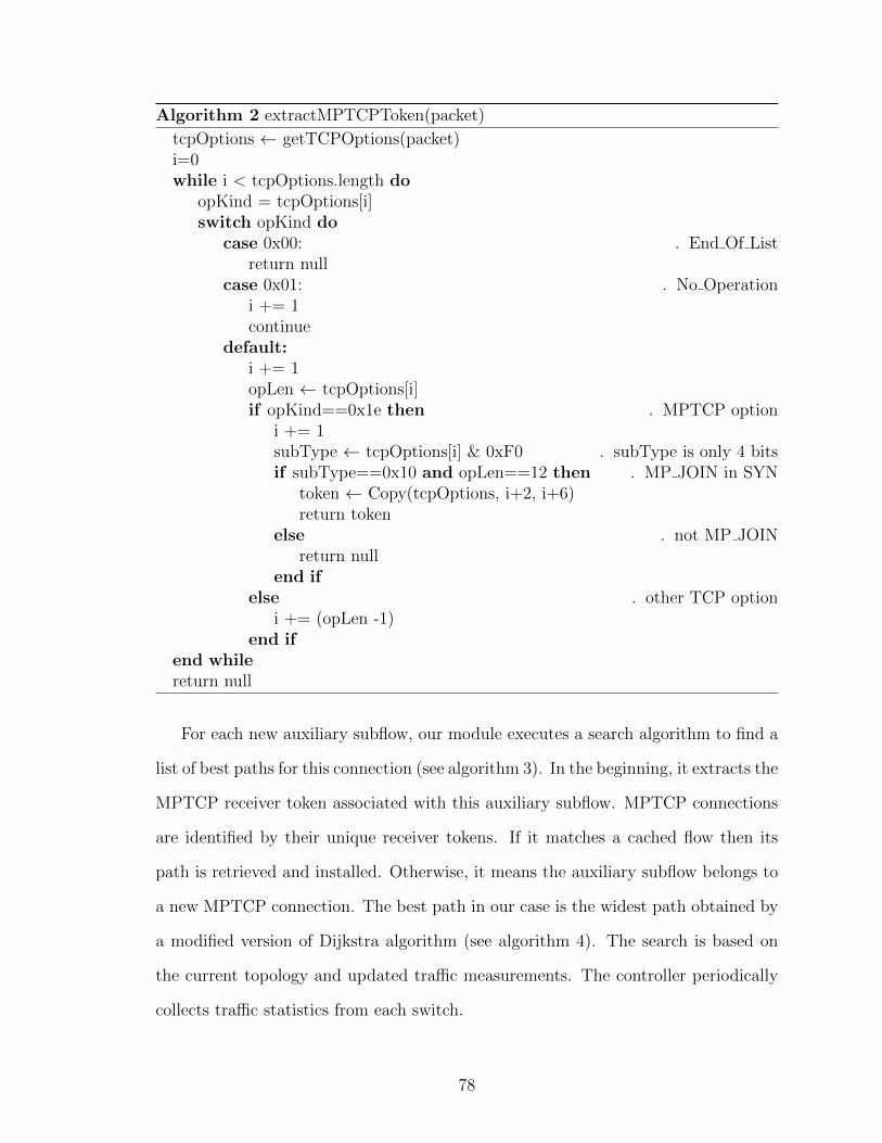
Algorithm 2 extractMPTCPToken(packet)
tcpOptions ← getTCPOptions(packet)i=0while i < tcpOptions.length do
opKind = tcpOptions[i]switch opKind do
case 0x00: . End Of Listreturn null
case 0x01: . No Operationi += 1continue
default:i += 1opLen ← tcpOptions[i]if opKind==0x1e then . MPTCP option
i += 1subType ← tcpOptions[i] & 0xF0 . subType is only 4 bitsif subType==0x10 and opLen==12 then . MP JOIN in SYN
token ← Copy(tcpOptions, i+2, i+6)return token
else . not MP JOINreturn null
end ifelse . other TCP option
i += (opLen -1)end if
end whilereturn null
For each new auxiliary subflow, our module executes a search algorithm to find a
list of best paths for this connection (see algorithm 3). In the beginning, it extracts the
MPTCP receiver token associated with this auxiliary subflow. MPTCP connections
are identified by their unique receiver tokens. If it matches a cached flow then its
path is retrieved and installed. Otherwise, it means the auxiliary subflow belongs to
a new MPTCP connection. The best path in our case is the widest path obtained by
a modified version of Dijkstra algorithm (see algorithm 4). The search is based on
the current topology and updated traffic measurements. The controller periodically
collects traffic statistics from each switch.
78

If the incoming PACKET IN message is for the first auxiliary subflow of an
MPTCP connection, the list of paths are cached for subsequent auxiliary subflows
of this connection. So the search algorithm needs to be executed only once for each
connection regardless of the number of its auxiliary subflows. The installed
OpenFlow rules have soft timeout and will be deleted after they become inactive.
The switches notify the controller of expired OpenFlow rules by sending
FLOW REMOVED message which will allow the controller to clear the
corresponding entry in the cached flows. Using this method does not interrupt
traffic that goes through the first subflow, which is routed using OpenFlow group
table rules without going to the controller. It only enables large flows to gain more
throughput and finish faster by utilizing multiple subflows, path diversity and SDN.
The congestion control for MPTCP adapts to changing traffic conditions and shifts
traffic from congested links to other subflows without harming existing TCP
connections.
Algorithm 3 getPath(packet)
token← extractMPTCPToken(packet)if exists(cachedPaths[token]) then
p← dequeue(cachedPaths[token])install(p)return
end iflinkCapacity← topology.getAvailableCapacity()for i← 0 to maxPaths-1 do
p← dijkstra(flow.src, flow.dst,linkCapacity)w← width(p)for l← p.links do
linkCapacity[l]← linkCapacity[l]-wend forcachedPaths[token].add(p)
end forp← dequeue(cachedPaths[token])install(p))
79

Algorithm 4 Dijkstra(s,v,graph)q← emptyvisited← emptyfor node← graph.nodes do
width[node]← 0previous[node]← null
end forwidth[s]←∞q.add(s)while q is not empty do
node← q.dequeue()if visited.contains(node) then
continueend ifvisited.add(node)for link← graph.connectedTo(node) do
neighbor← link.getDestination()altWidth← max(width[neighbor],
min(width[node],link.getWidth())if altWidth > width[neighbor] then
width[neighbor]← altWidthprevious[neighbor]← nodeq.add(neighbor)
end ifend for
end while
5.4.3 Socket API for Creating Auxiliary Subflows
In order for applications to exploit our SDN architecture, they need the ability to
create MPTCP subflows and mark DSCP in the same time. The Linux kernel MPTCP
implementation [61] (as of v0.92) does not provide this capability. Researchers in [62]
proposed enhanced socket API for MPTCP that extends Linux kernel implementation
to provide additional features. The enhanced socket API provides applications with
additional features that are not available in the original kernel implementation. The
purpose is to allow application developers to have more control on the operation
of MPTCP. The list of their API features include retrieving subflow information,
creating subflows, terminating subflows, and setting the DSCP field, among other
80

features.
Despite that the enhanced socket API provides more control over MPTCP
operations, they fall short of meeting our requirement. The reason is that setting
the DSCP can happen only after the subflow is initiated, which means it is not
possible to mark DSCP for SYN packets. In our SDN architecture, SYN packets
need to have a specific DSCP value so that it can be forwarded to the controller.
The controller needs to extract the MPTCP receiver tokens from SYN packets. The
tokens are used as unique keys for identifying MPTCP connections. In the current
OpenFlow specfications [27], it is not possible to create OpenFlow match rules
against TCP options. Therefore, we rely on the DSCP field to distinguish between
auxiliary subflows and other flows. The MPTCP token is sent only with MP JOIN
SYN packet during TCP three-way handshake. Maintaining MPTCP tokens allows
the controller to place auxiliary subflows of the same connection on best paths with
highest available capacity. To that end, we have developed new socket API that
allows applications to dynamically create DSCP-marked MPTCP subflows for an
existing MPTCP connection. The DSCP field is set with flow initiation (i.e., SYN
packet).
We describe briefly the enhanced socket API proposed in [62]. New
functionalities were implemented above the system calls getsockopt and
setsockopt. They introduced new socket options for querying kernel-level
information and performing actions on existing MPTCP connections. The socket
options include the following:
• MPTCP_GET_SUB_IDS: retrieve the current list of subflows IDs as viewed by the
kernel.
• MPTCP_GET_SUB_TUPLE: retrieve the IP address and port number of a specfic
subflow.
81

• MPTCP_OPEN_SUB_TUPLE: request to create a new subflow for an existing
MPTCP connection.
• MPTCP_CLOSE_SUB_ID: request to close a specific subflow.
• MPTCP_SUB_GETSOCKOPT: pass the socket option to getsockopt for a specific
subflow and return the result.
• MPTCP_SUB_SETSOCKOPT: pass the socket option to setsockopt for a specific
subflow.
Using MPTCP_SUB_SETSOCKOPT, it is possible to set DSCP value of a specific
subflow. However, as we discussed earlier, this happens only after the subflow has
already been initialized and three-way handshake packets exchanged. We introduce
new socket option MPTCP_OPEN_SUB_WITHTOS that creates a new subflow and marks
DSCP in the same time. That is, SYN packets will have the specified DSCP value.
The application needs to pass mptcp_newsub_withtos struct which is defined as
follows:
struct mptcp_newsub_withtos {
char *tosval; /* DSCP value */
struct mptcp_sub_tuple *sub; /* sub_tuple of the new subflow*/
}
The tosval member sets the value of DSCP field. Note that DSCP field is only 6-
bit length. Along with the two-bit ECN field, they replace what was previously known
as ToS field in the IP packet. The DSCP 6 bits are the most significant bits of tosval.
For example, the DSCP value (000111) is represented with hexadecimal value (0x1C)
because the two least-significant bits are set to zero (00011100). The sub member
holds the tuple information of the new subflow. Figure 5.8 shows an example of using
the new socket option MPTCP_OPEN_SUB_WITHTOS to create one additional subflow
that has the DSCP decimal value 28 (0x1C). The new subflow uses the same IP pair
82

and the same destination port of the existing subflow that has the ID subflow_id.
The subflow ID can be retrieved from the kernel using MPTCP_GET_SUB_IDS which
provides a list of active subflows with their IDs. The current implementation limits the
number of active subflows for a single MPTCP connection to 32 and the subflows are
assigned IDs within the range from 0 to 31 [62]. The source port of the new subflow is
randomly chosen by the kernel but can be specified if needed. The mptcp_sub_tuple
information are retrieved using MPTCP_GET_SUB_TUPLE.
Our modification to the Linux kernel is very minimal. It introduces new socket
API function that allows applications to specify the value of DSCP during subflow
initiation. Our work is based on Linux kernel MPTCP implementation v0.92 [61]. It
also extends the socket API proposed in [62].
The usage scenario for this extended API is that after a certain threshold of
transferred data, the application issues a call to create a new subflow. This should
happen only with large flows that take a lot of time to finish transferring data.
Specifying the threshold and the number of auxiliary subflows is left to the
application.
83

struct mptcp_newsub_withtos *newsub;
struct sockaddr *sin;
struct sockaddr_in *sin4;
unsigned int optlen, newlen;
int DSCPvalue = 28;
newlen = 100;
newsub = malloc(newlen);
if (!newsub) {
fprintf(stderr,"Error: malloc\n");
return 0;
}
newsub->tosval= (char *) &DSCPvalue;
optlen = 100;
newsub->sub = malloc(optlen);
if (!newsub->sub) {
fprintf(stderr,"Error: malloc\n");
return -1;
}
optlen = 100;
newsub->sub->id = subflow_id; // from MPTCP_GET_SUB_IDS
error = getsockopt(sock, IPPROTO_TCP, MPTCP_GET_SUB_TUPLE, newsub->sub
, &optlen);
if (error) {
fprintf(stderr,"MPTCP_GET_SUB_TUPLE error: %d\n", error);
free(newsub->sub);
free(newsub);
return -1;
}
sin = (struct sockaddr*) &newsub->sub->addrs[0];
if(sin->sa_family == AF_INET){
sin4 = (struct sockaddr_in*) &newsub->sub->addrs[0];
sin4->sin_port = htons(0); //source port for new flow
error = getsockopt(sock, IPPROTO_TCP, MPTCP_OPEN_SUB_WITHTOS,newsub
,&optlen);
if (error) {
fprintf(stderr,"MPTCP_OPEN_SUB_WITHTOS error: %d\n", error);
free(newsub->sub);
free(newsub);
return -1;
}
}
Figure 5.8: Creating new subflow with with DSCP
84
5.5 Evaluation
5.5.1 Experiments Setup
To evaluate our SDN architecture, we conducted experiments using the GENI testbed
environment. The network topology used is k-ary Fat Tree [45]. We deployed a 6-port
Fat Tree network that contains 45 switches and 54 hosts. The network topology is
shown in Figure 5.9. All host nodes were running Linux Ubuntu with the modified
MPTCP kernel. For switch nodes we used the software switch OpenvSwitch [22]. All
switch nodes connect to Floodlight controller [24] running our routing and monitoring
modules.
For traffic flows, we note that data center traffic patterns vary in size, arrival time,
and other properties. Researchers in [63] studied traffic traces in ten data centers and
found that approximately 80% of all flows are small in size and finish in less than 11
seconds in most studied data centers. To emulate traffic in data centers we generated
two traffic matrices that follow this observation. In traffic matrix TM1, 80% of flows
are small and in traffic matrix TM2 70% of flows are small. The traffic pattern is
random permutation where each host sends a flow to one random host (in a different
rack). The inter-arrival time is randomly chosen between 500 ms and 1000 ms. Each
traffic matrix contains 540 flows.
We developed a small application to generate traffic for our experiments. This
application can create auxiliary subflows using the new socket API. Auxiliary
subflows are initiated after transmitted traffic exceeds thresholds. The purpose of
this application is to test the new socket API and SDN controller application. The
threshold for creating each additional subflow is 1 MB. Each traffic matrix was
executed five times as follows:
1. Regular TCP and ECMP routing.
2. MPTCP with 2 subflows and ECMP routing.
85

Figure 5.9: Network topology
86
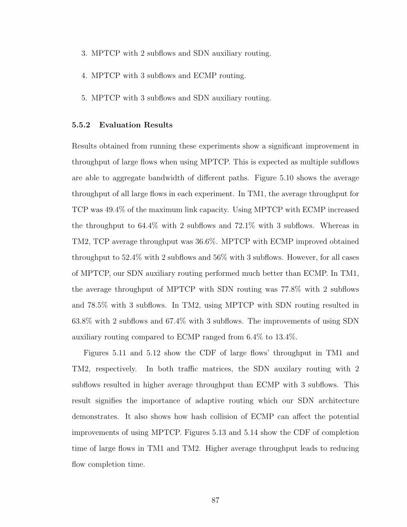
3. MPTCP with 2 subflows and SDN auxiliary routing.
4. MPTCP with 3 subflows and ECMP routing.
5. MPTCP with 3 subflows and SDN auxiliary routing.
5.5.2 Evaluation Results
Results obtained from running these experiments show a significant improvement in
throughput of large flows when using MPTCP. This is expected as multiple subflows
are able to aggregate bandwidth of different paths. Figure 5.10 shows the average
throughput of all large flows in each experiment. In TM1, the average throughput for
TCP was 49.4% of the maximum link capacity. Using MPTCP with ECMP increased
the throughput to 64.4% with 2 subflows and 72.1% with 3 subflows. Whereas in
TM2, TCP average throughput was 36.6%. MPTCP with ECMP improved obtained
throughput to 52.4% with 2 subflows and 56% with 3 subflows. However, for all cases
of MPTCP, our SDN auxiliary routing performed much better than ECMP. In TM1,
the average throughput of MPTCP with SDN routing was 77.8% with 2 subflows
and 78.5% with 3 subflows. In TM2, using MPTCP with SDN routing resulted in
63.8% with 2 subflows and 67.4% with 3 subflows. The improvements of using SDN
auxiliary routing compared to ECMP ranged from 6.4% to 13.4%.
Figures 5.11 and 5.12 show the CDF of large flows’ throughput in TM1 and
TM2, respectively. In both traffic matrices, the SDN auxilary routing with 2
subflows resulted in higher average throughput than ECMP with 3 subflows. This
result signifies the importance of adaptive routing which our SDN architecture
demonstrates. It also shows how hash collision of ECMP can affect the potential
improvements of using MPTCP. Figures 5.13 and 5.14 show the CDF of completion
time of large flows in TM1 and TM2. Higher average throughput leads to reducing
flow completion time.
87
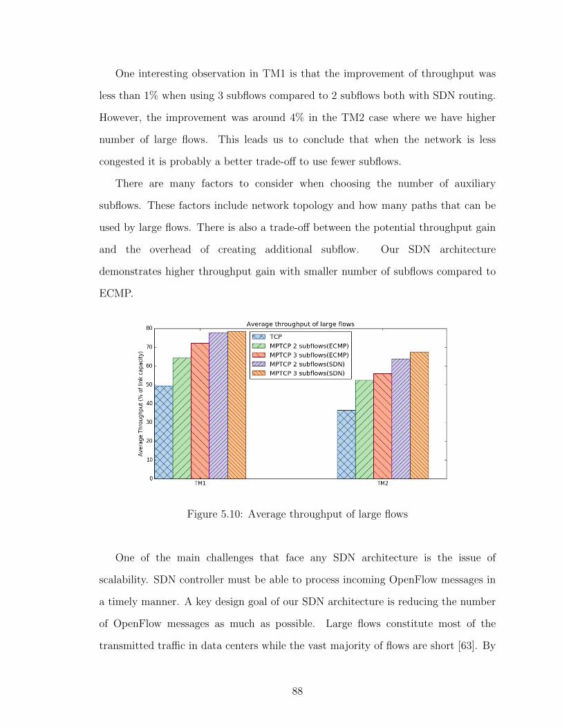
One interesting observation in TM1 is that the improvement of throughput was
less than 1% when using 3 subflows compared to 2 subflows both with SDN routing.
However, the improvement was around 4% in the TM2 case where we have higher
number of large flows. This leads us to conclude that when the network is less
congested it is probably a better trade-off to use fewer subflows.
There are many factors to consider when choosing the number of auxiliary
subflows. These factors include network topology and how many paths that can be
used by large flows. There is also a trade-off between the potential throughput gain
and the overhead of creating additional subflow. Our SDN architecture
demonstrates higher throughput gain with smaller number of subflows compared to
ECMP.
Figure 5.10: Average throughput of large flows
One of the main challenges that face any SDN architecture is the issue of
scalability. SDN controller must be able to process incoming OpenFlow messages in
a timely manner. A key design goal of our SDN architecture is reducing the number
of OpenFlow messages as much as possible. Large flows constitute most of the
transmitted traffic in data centers while the vast majority of flows are short [63]. By
88

Figure 5.11: Throughput of large flows (TM1)
Figure 5.12: Throughput of large flows (TM2)
forwarding only the auxiliary subflows of large flows to the SDN controller, we
reduce the number of OpenFlow messages. Hence, the load on SDN controller is
minimized.
89

Figure 5.13: Completion time of large flows (TM1)
Figure 5.14: Completion time of large flows (TM2)
5.6 Summary
In this chapter, we proposed an SDN-based architecture for using MPTCP in data
centers. In this architecture, additional MPTCP subflows are created on demand
using the modified Linux kernel. Experiments were conducted on the GENI testbed
90
environment to evaluate the use of MPTCP and OpenFlow. We show that using a
centralized controller can improve throughput of large flows, which leads to better
utilization of network resources.
91

Chapter 6
Conclusion
In this dissertation, we have studied various mechanisms that aim to improve the
quality of service provided to selected traffic flows. The main focus of this research
is to develop convenient methods and systems that have the ability to provide
various network applications with guaranteed quality of service. Our study focuses
on certain types of network traffic flows that have different aspects of QoS
requirements. Utilizing the software-defined networking architecture, we have
developed and evaluated three mechanisms. In the following, we summarize the
main contributions introduced in this research:
• An SDN-based QoS routing approach to improve the provisioning of quality of
service to bandwidth-demanding traffic flows. By having a centralized controller
that performs continuous monitoring of network measurements, the QoS routing
application places traffic flows on paths that have sufficient available capacity.
The evaluation results show that this approach can significantly improve the
throughput of bandwidth-demanding flows, compared with the shortest path
routing algorithm used in existing networks.
• A flexible framework for providing quality of service to latency-sensitive traffic.
Latency, an important QoS measurement for various network applications, is
92

affected by the queueing delay of network devices and also by the current state
of traversed path. Our SDN-based framework enables the timely delivery of
data packets belonging to latency-sensitive traffic. This framework provides
QoS to latency-sensitive traffic with the focus on defining priorities for different
traffic classes and the assigning mechanism of unused network capacity.
• An SDN-based architecture for maximizing the throughput of large flows by
using Multipath TCP. Traffic engineering in modern data center networks
should leverage available multi-path topologies. By using Multipath TCP and
SDN, we have developed a solution that maximizes throughput gain of large
flows. Our approach enables applications to achieve higher throughput for
large flows by dynamically creating multiple MPTCP subflows. These
MPTCP subflows are routed through least-congested paths by the centralized
SDN controller.
6.1 Future Work
There are several directions to extend the research presented in this dissertation. We
list the following:
• Defining additional traffic flows with different characteristics. This can include
traffic flows that have more than one parameter in their QoS requirements.
• Investigating the relationship between different QoS metrics. The
inter-dependency of QoS metrics is an interesting topic for composite
parameter QoS applications.
• Exploring different methods to gather network measurements. Instead of
querying the data plane periodically for statistics, we could use a push model
that exports such information. For example, we can use IPFIX protocol to
93
export statistics to a collector and then analyze them and perform actions
related to QoS provisioning and monitoring.
• Adaptive SDN-based load balancing using OpenFlow group tables. In chapter
5, we used OpenFlow group tables for load balancing with fixed weights. This
can be extended to employ an adaptive approach that adjusts the weights based
on the current network measurements.
94

Appendix
Lists of traffic flows used in the second experiment in Chapter 3.
Start, duration: in seconds
BW: iperf3 reported bandwidth in Kbps
Src Dst Start Duration Accepted BWh1 h18 14 200 Yes 9063h15 h2 26 178 Yes 8784h7 h17 41 189 Yes 6456h11 h4 55 182 Yes 9473h9 h13 69 197 No 6137h20 h16 83 179 Yes 9516h4 h5 95 160 Yes 7727h19 h10 110 197 Yes 7590h14 h19 122 176 No 9036h16 h7 135 179 No 7974h5 h1 148 162 No 8286h3 h8 160 203 No 8530h2 h9 171 203 No 8959h6 h15 183 163 No 5891h10 h20 197 209 No 9456h12 h14 208 181 No 6238h17 h11 222 188 No 7501h13 h3 236 151 No 6920h8 h12 248 159 Yes 9447h18 h6 261 169 No 6224
Src Dst Start Duration Accepted BWh1 h14 14 150 Yes 9411h14 h8 26 176 Yes 9159h5 h12 39 123 Yes 9610h13 h7 54 163 Yes 6681h6 h16 68 139 Yes 6313h4 h9 83 161 No 8188h9 h6 98 180 No 6804h19 h2 110 122 No 8209h12 h20 124 165 No 7658h10 h13 135 134 No 4629h8 h15 147 137 No 7311h16 h10 158 178 No 6757h2 h18 169 135 No 3792h15 h3 184 159 No 5033h20 h4 197 168 No 4859h7 h1 209 179 No 8980h17 h11 223 155 No 4223h11 h19 236 175 No 5080h18 h5 250 124 No 3201h3 h17 262 166 No 5798
Src Dst Start Duration Accepted BWh15 h5 13 135 Yes 9471h20 h16 25 144 Yes 9566h12 h18 40 166 Yes 9546h7 h11 55 128 Yes 9315h10 h7 67 139 Yes 9437h2 h15 79 164 Yes 7060h19 h1 93 137 Yes 7744h1 h13 107 166 No 6257h4 h12 122 162 Yes 9471h18 h3 134 155 No 7918h3 h6 146 95 No 3299h14 h9 161 128 No 5371h6 h19 175 91 No 3045h8 h10 187 112 No 5568h16 h2 198 149 No 5807h5 h20 212 113 No 4656h11 h17 223 65 Yes 8961h9 h4 234 94 Yes 8491h13 h8 245 105 No 7349h17 h14 256 170 Yes 9355
Src Dst Start Duration Accepted BWh8 h2 11 147 Yes 9563h18 h7 25 176 Yes 8783h7 h13 38 154 Yes 7731h16 h17 52 136 Yes 9144h10 h15 66 116 Yes 9569h14 h11 78 108 Yes 9527h11 h6 89 168 Yes 8292h5 h14 102 174 No 6829h9 h16 113 70 No 3954h15 h18 125 147 No 7911h19 h12 140 155 No 7327h12 h3 151 86 No 6647h1 h19 166 141 No 5694h6 h4 179 157 Yes 8589h2 h5 191 76 No 6601h13 h1 204 62 No 6225h4 h20 215 119 Yes 4620h17 h9 230 148 No 6069h20 h8 244 151 No 6339h3 h10 257 162 No 7441
95
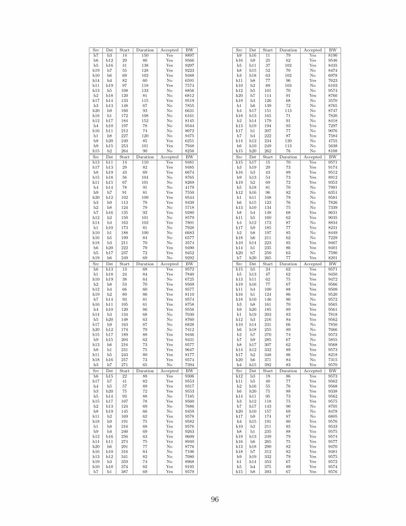
Src Dst Start Duration Accepted BWh7 h3 14 150 Yes 8897h6 h12 29 80 Yes 9566h5 h16 41 138 Yes 9297h19 h7 55 128 Yes 9223h10 h6 69 102 Yes 9488h14 h4 82 60 No 6591h11 h19 97 118 Yes 7574h13 h5 108 133 No 8856h2 h18 120 81 No 6812h17 h14 133 115 Yes 9519h3 h13 148 67 No 7855h20 h9 160 93 No 6631h18 h1 172 108 No 6161h12 h17 184 152 No 8145h4 h10 197 78 No 9544h16 h11 212 74 No 8072h1 h8 227 120 No 9475h8 h20 240 85 Yes 6251h9 h15 253 101 Yes 7948h15 h2 264 90 No 8256
Src Dst Start Duration Accepted BWh9 h16 11 79 Yes 8190h16 h9 25 62 Yes 9546h5 h11 37 102 Yes 8435h8 h15 52 70 No 8474h3 h18 63 102 No 6978h11 h8 77 96 Yes 7623h10 h2 89 103 No 6103h12 h5 101 70 No 9574h20 h7 114 91 Yes 8760h19 h3 126 68 No 3570h1 h6 139 72 No 8765h4 h17 151 113 No 8747h18 h13 165 71 No 7820h2 h14 179 91 No 8418h13 h19 194 93 Yes 7297h17 h1 207 77 No 9076h7 h4 222 87 Yes 7584h14 h12 234 120 No 4755h6 h10 249 113 No 5638h15 h20 262 76 No 8108
Src Dst Start Duration Accepted BWh13 h11 14 110 Yes 9481h17 h13 29 82 Yes 9485h8 h19 43 69 Yes 6674h15 h18 56 104 No 8765h11 h15 67 101 No 8269h4 h14 78 91 No 4179h9 h7 91 81 Yes 7550h20 h12 102 109 Yes 9544h3 h9 113 78 Yes 9439h2 h8 124 79 No 5718h7 h16 135 92 Yes 9280h12 h2 150 101 No 8579h14 h4 162 102 Yes 7801h1 h10 173 81 No 7928h10 h1 188 100 No 6683h16 h5 199 84 No 6577h18 h3 211 70 No 3574h6 h20 222 79 Yes 9490h5 h17 237 72 Yes 9452h19 h6 249 69 No 9292
Src Dst Start Duration Accepted BWh15 h17 15 70 Yes 9571h3 h19 29 73 Yes 9174h16 h3 43 89 Yes 9512h9 h13 54 73 Yes 8912h19 h2 69 72 Yes 9353h5 h18 81 70 No 7991h12 h16 96 82 No 6351h1 h11 108 79 No 9581h6 h15 123 76 No 7826h13 h10 134 75 No 7339h8 h4 148 68 Yes 9631h11 h5 160 62 Yes 9035h4 h12 173 87 No 8834h17 h9 185 77 Yes 8231h2 h8 197 85 No 8449h18 h6 211 62 No 7229h10 h14 223 85 Yes 9467h14 h1 235 86 Yes 9401h20 h7 250 63 No 7590h7 h20 265 77 Yes 8201
Src Dst Start Duration Accepted BWh6 h13 13 68 Yes 9572h1 h18 24 84 Yes 7840h10 h19 38 64 No 6725h2 h8 53 70 Yes 9569h12 h4 66 60 Yes 9577h19 h2 80 86 Yes 8110h7 h14 93 81 Yes 9574h16 h11 105 61 Yes 8758h4 h10 120 86 Yes 9556h14 h3 134 68 No 7030h5 h20 148 63 No 8760h17 h9 163 87 No 6828h20 h12 174 79 No 7412h15 h17 189 88 Yes 9446h9 h15 204 62 Yes 9431h13 h6 216 73 Yes 9577h8 h1 231 75 Yes 9647h11 h5 243 80 Yes 8177h18 h16 257 73 Yes 9574h3 h7 271 65 No 7394
Src Dst Start Duration Accepted BWh15 h5 24 62 Yes 9571h5 h13 47 62 Yes 9450h13 h11 62 75 Yes 9472h19 h16 77 67 Yes 9566h11 h4 100 88 Yes 9509h16 h1 124 86 Yes 9520h18 h10 146 86 No 9572h3 h8 161 70 Yes 9565h9 h20 185 89 Yes 9561h1 h19 203 83 Yes 7818h12 h3 216 84 Yes 9562h10 h14 231 66 No 7850h6 h18 255 89 No 7666h2 h7 270 74 Yes 9572h7 h9 285 67 No 5855h8 h17 307 62 Yes 9568h14 h12 332 89 Yes 9573h17 h2 348 86 Yes 8218h20 h6 371 84 No 7315h4 h15 392 83 Yes 9570
Src Dst Start Duration Accepted BWh6 h15 22 88 Yes 9306h17 h7 41 82 Yes 9553h4 h5 57 89 Yes 9317h3 h20 75 72 Yes 9553h5 h14 93 88 No 7185h15 h17 107 78 Yes 9560h2 h13 124 69 No 7686h8 h19 145 66 No 9459h11 h2 169 62 Yes 9578h18 h9 191 75 Yes 9582h1 h8 216 68 Yes 9576h9 h4 240 69 Yes 9263h12 h16 256 63 Yes 9609h14 h11 274 75 Yes 8940h20 h6 291 77 No 8776h16 h10 316 84 No 7106h13 h12 341 82 No 7080h19 h3 359 74 No 8968h10 h18 374 82 Yes 9195h7 h1 387 69 Yes 9579
Src Dst Start Duration Accepted BWh12 h3 19 86 Yes 9573h11 h5 40 77 Yes 9562h2 h16 55 76 Yes 9568h6 h20 75 88 Yes 9338h14 h11 95 73 Yes 9562h3 h12 118 75 Yes 9575h7 h17 143 90 No 8705h20 h10 157 69 No 8478h17 h9 174 87 No 6805h4 h15 191 80 Yes 9576h10 h2 211 85 Yes 9533h8 h1 235 88 Yes 9575h19 h13 249 79 Yes 9574h16 h6 265 75 Yes 9577h13 h18 290 82 Yes 9470h18 h7 312 82 Yes 9481h9 h19 332 79 Yes 9575h1 h14 353 67 Yes 9572h5 h4 375 89 Yes 9574h15 h8 393 67 Yes 9576
96

Src Dst Start Duration Accepted BWh9 h16 25 63 Yes 9565h4 h9 48 88 Yes 9564h5 h2 63 86 Yes 9037h3 h12 78 83 Yes 9504h15 h10 98 88 Yes 9571h8 h3 115 61 No 7619h13 h5 140 86 Yes 9570h6 h14 165 89 Yes 9434h18 h6 186 64 No 8474h19 h4 201 82 No 6954h16 h20 222 61 Yes 9566h20 h15 237 72 Yes 9443h17 h8 254 85 No 7828h10 h1 276 89 No 9484h12 h7 295 63 No 7437h1 h17 317 69 Yes 7465h11 h18 332 64 No 7152h7 h11 351 72 Yes 9072h14 h19 374 83 Yes 9573h2 h13 388 88 Yes 9577
Src Dst Start Duration Accepted BWh10 h6 22 73 Yes 9576h11 h5 47 72 Yes 9571h2 h7 65 69 Yes 7348h3 h19 88 63 No 8615h13 h17 111 76 Yes 9573h6 h14 131 84 Yes 9570h5 h20 149 80 No 9302h4 h10 174 67 Yes 9573h20 h3 194 68 Yes 9361h8 h11 219 72 No 8987h17 h15 239 77 Yes 9569h15 h12 257 90 Yes 9436h16 h4 282 74 Yes 8201h18 h9 303 78 No 7594h1 h18 324 79 Yes 7683h14 h1 345 85 No 9442h12 h13 366 86 Yes 8581h19 h16 391 74 Yes 9580h9 h8 411 71 No 7772h7 h2 429 70 Yes 9579
Src Dst Start Duration Accepted BWh5 h3 22 79 Yes 9573h10 h6 47 78 Yes 9570h11 h2 67 76 Yes 9573h1 h15 85 70 Yes 9572h8 h9 103 77 Yes 9574h2 h5 121 74 Yes 8920h16 h17 141 68 Yes 9280h3 h12 164 68 No 8122h15 h19 184 79 No 8270h20 h16 205 61 Yes 9203h14 h18 229 80 Yes 9586h18 h10 250 62 Yes 9451h19 h14 270 72 No 9343h6 h13 295 78 Yes 9567h17 h8 319 73 No 9573h9 h20 344 71 Yes 9575h13 h11 364 71 Yes 9552h12 h4 386 75 Yes 9563h4 h7 408 66 Yes 9416h7 h1 430 71 Yes 9477
Src Dst Start Duration Accepted BWh14 h4 22 77 Yes 9570h17 h1 43 62 Yes 9565h3 h15 68 68 Yes 9567h5 h10 91 64 Yes 9570h8 h3 111 70 Yes 9560h2 h17 134 67 Yes 9572h16 h5 158 70 Yes 9575h13 h8 182 73 Yes 9574h1 h18 206 68 Yes 9579h15 h9 231 77 No 8236h7 h12 256 73 No 7622h19 h16 279 63 Yes 9562h18 h6 301 79 Yes 9119h9 h19 326 62 Yes 9571h11 h20 345 62 Yes 8693h10 h14 370 70 No 8012h12 h2 393 66 No 9242h4 h13 413 78 Yes 9569h20 h7 436 80 No 9222h6 h11 459 71 Yes 9569
Src Dst Start Duration Accepted BWh13 h18 16 185 Yes 9418h18 h15 32 203 Yes 9408h8 h17 51 192 Yes 6632h3 h13 67 169 Yes 9091h1 h9 85 203 Yes 9333h6 h12 101 201 No 6361h5 h11 119 160 No 4489h7 h2 137 197 Yes 8241h9 h19 157 201 No 8958h4 h5 176 150 No 7804h16 h3 193 210 No 6407h11 h14 209 189 No 7663h14 h4 227 154 Yes 6564h2 h20 244 179 No 6762h12 h1 262 168 No 8597h15 h8 280 160 No 7669h19 h10 297 166 No 8080h17 h6 316 179 No 3509h10 h7 332 185 No 7610h20 h16 350 194 Yes 9518
Src Dst Start Duration Accepted BWh5 h2 20 165 Yes 9565h18 h10 39 205 Yes 7168h8 h19 57 191 Yes 7996h4 h14 75 203 Yes 7913h20 h11 94 187 No 5164h11 h18 111 186 No 5952h19 h1 131 201 No 5828h16 h20 148 168 No 8524h14 h3 167 171 Yes 6929h15 h5 186 209 No 6833h2 h13 202 199 No 8579h9 h16 221 183 No 3420h3 h17 239 172 No 5273h10 h7 255 161 Yes 6791h13 h4 275 157 No 5530h7 h9 292 154 Yes 4566h17 h8 310 163 No 5337h1 h12 326 166 No 6778h12 h6 345 160 No 5585h6 h15 365 164 No 7967
Src Dst Start Duration Accepted BWh7 h1 20 128 Yes 9493h8 h13 39 125 Yes 9485h19 h7 57 126 Yes 9282h14 h6 76 179 Yes 9524h1 h8 92 128 Yes 9252h12 h2 109 165 Yes 8975h15 h17 128 175 Yes 7249h17 h11 145 143 No 7418h10 h14 163 126 Yes 9506h16 h19 179 133 No 8038h3 h15 196 152 No 8016h18 h5 215 168 No 6726h11 h4 232 162 No 8969h2 h18 248 178 No 6888h20 h10 265 126 No 6427h6 h16 285 149 No 8603h5 h3 302 162 Yes 9484h13 h12 319 161 Yes 8909h9 h20 335 167 No 7648h4 h9 354 160 No 8540
Src Dst Start Duration Accepted BWh10 h18 20 136 Yes 9402h8 h10 38 135 Yes 9346h13 h7 56 126 Yes 7966h17 h5 72 145 Yes 9576h14 h1 90 174 No 7391h15 h19 107 122 Yes 9551h4 h12 127 141 Yes 8960h6 h11 144 125 No 8568h16 h2 162 167 No 7392h19 h16 179 124 Yes 8867h2 h15 195 179 Yes 6963h3 h9 215 176 No 8563h18 h4 232 158 Yes 7739h20 h14 249 167 No 8340h12 h20 266 138 Yes 8601h7 h13 283 168 No 8682h9 h3 301 156 No 7530h11 h6 319 162 Yes 9570h1 h8 336 156 No 9372h5 h17 353 134 No 8686
97

Src Dst Start Duration Accepted BWh17 h12 18 129 Yes 9427h7 h17 38 171 Yes 7305h11 h14 54 121 Yes 9372h13 h20 74 129 No 7592h1 h10 92 168 Yes 8626h16 h6 110 144 Yes 7945h15 h5 128 160 No 7245h4 h19 148 122 No 6291h20 h1 168 138 Yes 7506h8 h4 185 142 Yes 8252h5 h2 202 135 No 6416h19 h9 218 170 No 7830h12 h13 237 121 Yes 5933h10 h8 255 155 Yes 6269h9 h16 275 128 No 3793h18 h15 295 136 Yes 9469h6 h18 311 138 Yes 6048h14 h3 329 152 Yes 7875h3 h11 346 158 Yes 9404h2 h7 363 130 Yes 9571
Src Dst Start Duration Accepted BWh13 h20 20 125 Yes 9567h1 h5 38 124 Yes 8124h17 h14 57 129 Yes 9568h4 h6 77 140 Yes 9218h3 h7 97 112 No 8495h18 h2 114 134 Yes 7829h15 h9 130 115 Yes 8818h19 h12 148 106 No 7300h7 h18 166 135 Yes 6778h10 h8 182 113 No 8233h16 h10 201 104 No 8137h2 h11 220 116 No 9480h5 h4 238 108 Yes 9572h11 h13 257 110 Yes 9327h12 h16 277 137 No 6176h6 h15 297 106 No 6556h20 h3 317 157 Yes 7179h9 h1 333 148 No 7561h8 h19 349 116 No 8934h14 h17 365 159 Yes 9566
Src Dst Start Duration Accepted BWh4 h8 16 158 Yes 9405h20 h3 34 113 Yes 9465h12 h1 52 111 Yes 9367h14 h7 71 119 Yes 8430h17 h13 90 109 Yes 9566h15 h9 109 157 No 6840h11 h16 126 136 No 3447h6 h18 144 160 Yes 8103h5 h15 163 151 No 3661h13 h6 180 159 No 7768h18 h2 197 123 Yes 9476h9 h20 216 117 Yes 7743h10 h17 233 149 No 6880h7 h12 250 100 Yes 9107h1 h5 266 141 Yes 9037h16 h4 283 117 No 7012h8 h11 303 114 Yes 9574h2 h19 323 121 No 7923h19 h10 339 158 Yes 8807h3 h14 356 123 No 8201
Src Dst Start Duration Accepted BWh11 h16 17 159 Yes 7325h17 h15 36 122 Yes 9564h14 h9 54 101 Yes 9536h9 h18 72 121 No 5343h6 h20 90 133 No 5771h19 h13 109 102 No 9441h10 h4 127 119 Yes 9460h4 h6 146 111 Yes 8524h3 h11 165 116 Yes 9565h15 h1 184 145 Yes 9567h2 h5 204 125 No 8241h12 h7 221 123 Yes 9563h8 h19 239 110 Yes 9572h5 h2 259 118 Yes 6880h18 h14 278 128 Yes 9570h7 h12 297 130 No 5782h13 h10 314 138 No 5750h1 h17 330 153 Yes 9603h20 h8 346 137 No 5782h16 h3 363 123 Yes 7961
Src Dst Start Duration Accepted BWh20 h11 17 160 Yes 9568h7 h3 34 158 Yes 9545h13 h18 50 132 Yes 9567h1 h8 66 147 Yes 8265h19 h14 83 139 Yes 9570h4 h7 100 158 Yes 9229h8 h17 117 155 Yes 7293h2 h5 136 124 No 8049h6 h9 155 108 No 7641h11 h6 172 141 No 6367h16 h10 190 101 No 8886h5 h1 209 115 Yes 7036h10 h19 227 156 No 7389h9 h20 243 117 No 6255h15 h2 263 149 No 6913h12 h16 281 111 Yes 8258h18 h15 299 147 Yes 9495h17 h12 316 123 Yes 8942h3 h13 334 121 No 8153h14 h4 353 102 No 7813
Src Dst Start Duration Accepted BWh6 h15 16 90 Yes 9403h4 h10 34 100 Yes 8918h1 h13 52 82 Yes 7630h2 h11 68 89 No 6807h3 h14 84 105 No 8418h8 h17 102 85 No 9101h12 h6 122 104 Yes 8735h10 h4 139 112 Yes 8559h19 h8 156 114 Yes 7955h9 h1 176 102 No 6376h16 h3 195 113 No 7766h18 h2 215 82 No 4754h5 h20 234 114 Yes 8453h11 h7 252 85 Yes 9575h14 h12 270 80 No 7550h15 h19 288 116 No 8148h17 h16 308 113 Yes 8179h13 h5 326 83 No 8460h7 h18 342 110 Yes 9572h20 h9 362 103 Yes 9570
Src Dst Start Duration Accepted BWh8 h13 20 71 Yes 9561h2 h5 44 91 Yes 9576h9 h8 69 88 Yes 9570h11 h4 93 85 Yes 9574h10 h3 114 79 Yes 8788h18 h15 138 71 No 6781h5 h11 161 99 Yes 9570h16 h17 184 95 Yes 7719h13 h9 204 83 Yes 6541h17 h12 225 96 Yes 9187h3 h7 248 100 Yes 9503h7 h19 272 97 Yes 9102h19 h16 297 74 No 8223h4 h18 319 70 No 6482h6 h14 344 76 Yes 9562h20 h1 364 86 Yes 9394h12 h20 389 71 No 9366h14 h2 410 92 Yes 8111h15 h10 435 94 No 7352h1 h6 458 81 Yes 9561
Src Dst Start Duration Accepted BWh3 h6 22 79 Yes 9568h20 h14 47 85 Yes 95641h4 h10 70 93 Yes 9569h16 h18 91 89 Yes 9572h17 h13 115 80 Yes 9511h2 h20 136 85 Yes 8229h7 h17 160 90 No 7450h12 h8 185 96 No 6413h19 h5 208 89 Yes 6613h15 h9 228 77 Yes 6595h14 h7 253 71 Yes 7524h5 h3 276 79 Yes 7920h11 h2 301 98 No 7525h8 h19 323 96 Yes 9572h9 h4 347 83 Yes 8966h10 h15 372 77 Yes 9575h6 h1 397 72 No 7974h1 h11 420 84 Yes 9437h18 h16 441 91 Yes 9574h13 h12 463 88 Yes 9568
98
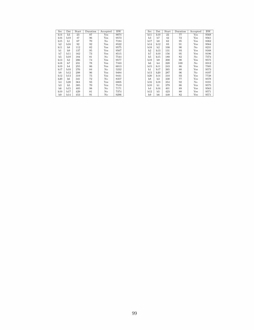
Src Dst Start Duration Accepted BWh14 h3 23 87 Yes 9074h16 h19 47 96 Yes 9573h15 h1 67 70 No 7184h2 h16 92 92 Yes 8522h11 h8 112 82 Yes 9575h1 h9 137 95 Yes 9567h7 h11 162 73 Yes 8515h5 h18 184 81 No 7544h13 h2 206 74 Yes 9577h18 h7 231 78 Yes 7163h19 h4 255 86 Yes 6013h17 h10 276 84 No 5232h8 h12 298 96 Yes 9484h12 h13 319 75 Yes 9441h20 h6 341 72 No 8357h4 h20 364 93 Yes 6805h3 h5 385 70 Yes 7519h6 h15 405 98 No 7171h10 h17 429 81 No 7374h9 h14 453 91 No 9296
Src Dst Start Duration Accepted BWh11 h19 22 77 Yes 9568h3 h7 42 72 Yes 9561h17 h8 62 95 Yes 8362h14 h12 83 91 Yes 9564h18 h2 108 90 No 8231h2 h13 131 93 Yes 9168h7 h10 156 95 Yes 9196h5 h15 180 82 No 7374h19 h9 200 98 Yes 9575h6 h4 220 100 No 8312h15 h11 243 86 Yes 7585h1 h17 265 88 Yes 9573h13 h20 287 96 No 8107h20 h14 310 93 Yes 7728h8 h3 330 77 Yes 9578h16 h18 354 92 No 8191h10 h1 379 86 Yes 9575h4 h16 401 89 Yes 9563h12 h5 423 88 Yes 9571h9 h6 448 82 Yes 9571
99

Bibliography
[1] ITU-T, “One way transmission time, itu-t recommendation g. 114,” 2003.Available at https://www.itu.int/rec/T-REC-G.114-200305-I.
[2] R. Braden, D. Clark, and S. Shenker, “Integrated services in the internetarchitecture: an overview. rfc 1633,” 1994.
[3] L. Zhang, S. Berson, S. Herzog, and S. Jamin, “Resource reservation protocol(rsvp)–version 1 functional specification. rfc 2205,” 1997.
[4] X. Xiao and L. M. Ni, “Internet qos: A big picture,” IEEE network, vol. 13,no. 2, pp. 8–18, 1999.
[5] K. Nichols, D. L. Black, S. Blake, and F. Baker, “Definition of the differentiatedservices field (ds field) in the ipv4 and ipv6 headers. rfc 2474,” 1998.
[6] Z. Wang and J. Crowcroft, “Quality-of-service routing for supporting multimediaapplications,” IEEE Journal on selected areas in communications, vol. 14, no. 7,pp. 1228–1234, 1996.
[7] S. Chen and K. Nahrstedt, “An overview of quality of service routing for next-generation high-speed networks: problems and solutions,” IEEE network, vol. 12,no. 6, pp. 64–79, 1998.
[8] M. Curado and E. Monteiro, “A survey of qos routing algorithms,” inProceedings of the International Conference on Information Technology (ICIT2004), Istanbul, Turkey, 2004.
[9] F. Kuipers, P. Van Mieghem, T. Korkmaz, and M. Krunz, “An overviewof constraint-based path selection algorithms for qos routing,” IEEECommunications Magazine, vol. 40, no. 12, pp. 50–55, 2002.
[10] T. Korkmaz and M. Krunz, “Multi-constrained optimal path selection,” in IEEEINFOCOM, vol. 2, pp. 834–843, Citeseer, 2001.
[11] A. Juttner, B. Szviatovski, I. Mecs, and Z. Rajko, “Lagrange relaxationbased method for the qos routing problem,” in INFOCOM 2001. TwentiethAnnual Joint Conference of the IEEE Computer and Communications Societies.Proceedings. IEEE, vol. 2, pp. 859–868, IEEE, 2001.
100

[12] X. Masip-Bruin, M. Yannuzzi, J. Domingo-Pascual, A. Fonte, M. Curado,E. Monteiro, F. Kuipers, P. Van Mieghem, S. Avallone, G. Ventre, et al.,“Research challenges in qos routing,” Computer communications, vol. 29, no. 5,pp. 563–581, 2006.
[13] S. Chen, M. Song, and S. Sahni, “Two techniques for fast computation ofconstrained shortest paths,” IEEE/ACM Transactions on Networking (TON),vol. 16, no. 1, pp. 105–115, 2008.
[14] D. Kreutz, F. M. Ramos, P. E. Verissimo, C. E. Rothenberg, S. Azodolmolky, andS. Uhlig, “Software-defined networking: A comprehensive survey,” Proceedingsof the IEEE, vol. 103, no. 1, pp. 14–76, 2015.
[15] N. Feamster, J. Rexford, and E. Zegura, “The road to sdn: an intellectual historyof programmable networks,” ACM SIGCOMM Computer CommunicationReview, vol. 44, no. 2, pp. 87–98, 2014.
[16] M. Caesar, D. Caldwell, N. Feamster, J. Rexford, A. Shaikh, and J. van derMerwe, “Design and implementation of a routing control platform,” inProceedings of the 2Nd Conference on Symposium on Networked Systems Designand Implementation-Volume 2, pp. 15–28, USENIX Association, 2005.
[17] A. Greenberg, G. Hjalmtysson, D. A. Maltz, A. Myers, J. Rexford, G. Xie,H. Yan, J. Zhan, and H. Zhang, “A clean slate 4d approach to network controland management,” ACM SIGCOMM Computer Communication Review, vol. 35,no. 5, pp. 41–54, 2005.
[18] M. Casado, M. J. Freedman, J. Pettit, J. Luo, N. McKeown, and S. Shenker,“Ethane: Taking control of the enterprise,” in ACM SIGCOMM ComputerCommunication Review, vol. 37, pp. 1–12, ACM, 2007.
[19] M. Casado, T. Garfinkel, A. Akella, M. J. Freedman, D. Boneh, N. McKeown,and S. Shenker, “Sane: A protection architecture for enterprise networks.,” inUSENIX Security Symposium, vol. 49, pp. 137–151, 2006.
[20] N. McKeown, T. Anderson, H. Balakrishnan, G. Parulkar, L. Peterson,J. Rexford, S. Shenker, and J. Turner, “Openflow: enabling innovation in campusnetworks,” ACM SIGCOMM Computer Communication Review, vol. 38, no. 2,pp. 69–74, 2008.
[21] B. A. A. Nunes, M. Mendonca, X.-N. Nguyen, K. Obraczka, and T. Turletti,“A survey of software-defined networking: Past, present, and future ofprogrammable networks,” IEEE Communications Surveys & Tutorials, vol. 16,no. 3, pp. 1617–1634, 2014.
[22] B. Pfaff, J. Pettit, T. Koponen, E. J. Jackson, A. Zhou, J. Rajahalme, J. Gross,A. Wang, J. Stringer, P. Shelar, et al., “The design and implementation of openvswitch.,” in NSDI, pp. 117–130, 2015.
101

[23] B. Pfaff, J. Pettit, K. Amidon, M. Casado, T. Koponen, and S. Shenker,“Extending networking into the virtualization layer.,” in Hotnets, 2009.
[24] “Floodlight,” 2017. Available at http://www.projectfloodlight.org.
[25] H. E. Egilmez, S. T. Dane, K. T. Bagci, and A. M. Tekalp, “Openqos: Anopenflow controller design for multimedia delivery with end-to-end quality ofservice over software-defined networks,” in Signal & Information processingassociation annual summit and conference (APSIPA ASC), 2012 Asia-Pacific,pp. 1–8, IEEE, 2012.
[26] H. Owens II and A. Durresi, “Video over software-defined networking (vsdn),”Computer Networks, vol. 92, pp. 341–356, 2015.
[27] O. N. F. (ONF), “Openflow switch specification 1.5.1,” 2015. Availableat https://www.opennetworking.org/wp-content/uploads/2014/10/
openflow-switch-v1.5.1.pdf.
[28] D. Erickson, “The beacon openflow controller,” in Proceedings of the second ACMSIGCOMM workshop on Hot topics in software defined networking, pp. 13–18,ACM, 2013.
[29] “Mininet,” 2017. Available at http://mininet.org/.
[30] “iperf3,” 2017. Available at https://iperf.fr/.
[31] N. L. Van Adrichem, C. Doerr, and F. A. Kuipers, “Opennetmon: Networkmonitoring in openflow software-defined networks,” in Network Operations andManagement Symposium (NOMS), 2014 IEEE, pp. 1–8, IEEE, 2014.
[32] P. E. McKenney, “Stochastic fairness queueing,” in INFOCOM’90, Ninth AnnualJoint Conference of the IEEE Computer and Communication Societies. TheMultiple Facets of Integration. Proceedings, IEEE, pp. 733–740, IEEE, 1990.
[33] “Htb,” 2017. Available at http://luxik.cdi.cz/~devik/qos/htb/index.htm.
[34] I. Stoica, H. Zhang, and T. Ng, A hierarchical fair service curve algorithm forlink-sharing, real-time and priority services, vol. 27. ACM, 1997.
[35] R. Wallner and R. Cannistra, “An sdn approach: quality of service usingbig switchs floodlight open-source controller,” Proceedings of the Asia-PacificAdvanced Network, vol. 35, pp. 14–19, 2013.
[36] D. Palma, J. Goncalves, B. Sousa, L. Cordeiro, P. Simoes, S. Sharma, andD. Staessens, “The queuepusher: Enabling queue management in openflow,”in Software Defined Networks (EWSDN), 2014 Third European Workshop on,pp. 125–126, IEEE, 2014.
102

[37] C. Caba and J. Soler, “Apis for qos configuration in software defined networks,”in Network Softwarization (NetSoft), 2015 1st IEEE Conference on, pp. 1–5,IEEE, 2015.
[38] O. N. Foundation, “Openflow management and configuration protocol,”2014. Available at https://www.opennetworking.org/images/stories/
downloads/sdn-resources/onf-specifications/openflow-config/
of-config-1.2.pdf.
[39] B. Pfaff and B. Davie, “The open vswitch database management protocol. rfc7047.,” 2013.
[40] “Json-rpc 1.0 specification,” 2005. Available at http://www.jsonrpc.org/
specification_v1.
[41] “Open vswitch database schema,” 2017. Available at http://www.
openvswitch.org/ovs-vswitchd.conf.db.5.pdf.
[42] M. Berman, J. S. Chase, L. Landweber, A. Nakao, M. Ott, D. Raychaudhuri,R. Ricci, and I. Seskar, “Geni: A federated testbed for innovative networkexperiments,” Computer Networks, vol. 61, pp. 5–23, 2014.
[43] M. Al-Fares, S. Radhakrishnan, B. Raghavan, N. Huang, and A. Vahdat,“Hedera: Dynamic flow scheduling for data center networks.,” in NSDI, vol. 10,pp. 19–19, 2010.
[44] D. Wischik, C. Raiciu, A. Greenhalgh, and M. Handley, “Design, implementationand evaluation of congestion control for multipath tcp.,” in NSDI, vol. 11, pp. 8–8, 2011.
[45] M. Al-Fares, A. Loukissas, and A. Vahdat, “A scalable, commodity data centernetwork architecture,” in ACM SIGCOMM Computer Communication Review,vol. 38, pp. 63–74, ACM, 2008.
[46] C. Clos, “A study of non-blocking switching networks,” Bell Labs TechnicalJournal, vol. 32, no. 2, pp. 406–424, 1953.
[47] C. Guo, G. Lu, D. Li, H. Wu, X. Zhang, Y. Shi, C. Tian, Y. Zhang, and S. Lu,“Bcube: a high performance, server-centric network architecture for modulardata centers,” ACM SIGCOMM Computer Communication Review, vol. 39,no. 4, pp. 63–74, 2009.
[48] A. Singla, C.-Y. Hong, L. Popa, and P. B. Godfrey, “Jellyfish: Networking datacenters randomly.,” in NSDI, vol. 12, pp. 17–17, 2012.
[49] A. Greenberg, J. R. Hamilton, N. Jain, S. Kandula, C. Kim, P. Lahiri, D. A.Maltz, P. Patel, and S. Sengupta, “Vl2: a scalable and flexible data centernetwork,” in ACM SIGCOMM computer communication review, vol. 39, pp. 51–62, ACM, 2009.
103

[50] A. Ford, C. Raiciu, M. Handley, and O. Bonaventure, “Tcp extensions formultipath operation with multiple addresses. rfc 6824,” 2013.
[51] V. Paxson, M. Allman, J. Chu, and M. Sargent, “Computing tcp’s retransmissiontimer. rfc 6298,” 2011.
[52] C. Raiciu, M. Handley, and D. Wischik, “Coupled congestion control formultipath transport protocols. rfc 6356,” 2011.
[53] A. R. Curtis, W. Kim, and P. Yalagandula, “Mahout: Low-overhead datacentertraffic management using end-host-based elephant detection,” in INFOCOM,2011 Proceedings IEEE, pp. 1629–1637, IEEE, 2011.
[54] A. Agache and C. Raiciu, “Oh flow, are thou happy? tcp sendbuffer advertisingfor make benefit of clouds and tenants.,” in HotCloud, 2015.
[55] C. Raiciu, S. Barre, C. Pluntke, A. Greenhalgh, D. Wischik, and M. Handley,“Improving datacenter performance and robustness with multipath tcp,” in ACMSIGCOMM Computer Communication Review, vol. 41, pp. 266–277, ACM, 2011.
[56] M. Sandri, A. Silva, L. A. Rocha, and F. L. Verdi, “On the benefits of usingmultipath tcp and openflow in shared bottlenecks,” in Advanced InformationNetworking and Applications (AINA), 2015 IEEE 29th International Conferenceon, pp. 9–16, IEEE, 2015.
[57] S. Zannettou, M. Sirivianos, and F. Papadopoulos, “Exploiting path diversity indatacenters using mptcp-aware sdn,” in Computers and Communication (ISCC),2016 IEEE Symposium on, pp. 539–546, IEEE, 2016.
[58] M. Kheirkhah, I. Wakeman, and G. Parisis, “Mmptcp: A multipath transportprotocol for data centers,” in Computer Communications, IEEE INFOCOM2016-The 35th Annual IEEE International Conference on, pp. 1–9, IEEE, 2016.
[59] IANA, “Differentiated services field codepoints (dscp),” 2017. Availableat https://www.iana.org/assignments/dscp-registry/dscp-registry.
xhtml.
[60] IANA, “Transmission control protocol (tcp) parameters,” 2017. Availableat https://www.iana.org/assignments/tcp-parameters/tcp-parameters.
xhtml.
[61] C. Paasch, S. Barre, et al., “Multipath tcp in the linux kernel,” 2013. Availableat https://www.multipath-tcp.org.
[62] B. Hesmans and O. Bonaventure, “An enhanced socket api for multipath tcp.,”in ANRW, pp. 1–6, 2016.
[63] T. Benson, A. Akella, and D. A. Maltz, “Network traffic characteristics of datacenters in the wild,” in Proceedings of the 10th ACM SIGCOMM conference onInternet measurement, pp. 267–280, ACM, 2010.
104
Vita
• Education
– B.Sc., King Saud University, 2003
– M.Sc., King Saud University, 2006
– Ph.D., University of Kentucky, 2018
• Publications
– F. Alharbi, and Z. Fei, “Improving the Quality of Service for Critical FlowsIn Smart Grid Using Software-Defined Networking”, IEEE InternationalConference on Smart Grid Communications (SmartGridComm), 2016.
– F. Alharbi, and Z. Fei, “An SDN Architecture for Improving Throughputof Large Flows Using Multipath TCP”, The 5th IEEE InternationalConference on Cyber Security and Cloud Computing (IEEE CSCloud),2018.
105


