California High-Speed Train Project
Agreement No.: HSR 13-06 Book 2, Part C, Subpart 1
Scope of Work
Revision No. Date Description 0 01 Mar 12 Initial Release, R0 1 27 Apr 12 Addendum 1 2 04 Jun 12 Addendum 2 3 27 Jun 12 Addendum 3 4 31 Jul 12 Addendum 4 5 11 Oct 12 Addendum 5 6 02 Nov 12 Addendum 6 7 14 Dec 12 Addendum 7 8 03 Jan 13 Addendum 9 9 31 Jul 13 EXECUTION VERSION
HSR
13-
06 -
EXEC
UTI
ON
VER
SIO
NH
SR 1
3-06
- EX
ECU
TIO
N V
ERSI
ON
HSR
13-
06 -
EXEC
UTI
ON
VER
SIO
N

California High-Speed Train Project Agreement No.: HSR13-06
Book 2, Part C, Subpart1 – Scope of Work EXECUTION VERSION
THIS PAGE INTENTIONALLY LEFT BLANK
HSR
13-
06 -
EXEC
UTI
ON
VER
SIO
NH
SR 1
3-06
- EX
ECU
TIO
N V
ERSI
ON
HSR
13-
06 -
EXEC
UTI
ON
VER
SIO
N

Agreement No.: HSR13-06 California High-Speed Train Project
Page i of ii Book 2, Part C, Subpart 1 – Scope of Work
EXECUTION VERSION Table of Contents
Table of Contents
PART C – SCOPE OF WORK ...................................................................................................................... 1 1 CALIFORNIA HIGH SPEED TRAIN PROJECT (CHSTP) STANDARDS AND MANUALS.............................................. 1 2 PRELIMINARY ENGINEERING DOCUMENTS ............................................................................................... 2 3 PROJECT DESCRIPTION AND LIMITS ........................................................................................................ 4
3.1 CP1A, Hybrid Alternative Segment– South of Avenue 17 to North of Veterans Boulevard (alignment generally along the existing BNSF Railway) ............................................................. 4
3.2 CP1A, Remaining Alignment Segment – North of Veterans Boulevard to North of Stanislaus Street 5
3.3 CP1B Segment – North of Stanislaus Street to South of Santa Clara Street ................................ 6 3.4 CP1C, Alignment F1, Segment – South of Santa Clara Street to South of East American Avenue 6 3.5 Limits of Work for Enabling Facilities ........................................................................................ 7
4 PROJECT SCOPE OF WORK ................................................................................................................... 9 4.1 General .................................................................................................................................... 9 4.2 Design Services ...................................................................................................................... 12
4.2.1 Review of Design Criteria, Drawings, Reports and Specifications .................................................. 12 4.2.1.1 CHSTP Design Criteria ............................................................................................................................12 4.2.1.2 Preliminary Engineering Documents: Drawings and Reports ...................................................................12 4.2.1.3 Specifications ........................................................................................................................................12 4.2.1.4 Fresno Street Construction Plans and Specifications by Caltrans .............................................................13
4.2.2 Review of Environmental Documents .......................................................................................... 14 4.3 Additional Data ...................................................................................................................... 14 4.4 Design and Code Analysis ....................................................................................................... 14 4.5 e Certification Program .......................................................................................................... 14 4.6 Interface Coordination and Design Integration ....................................................................... 15 4.7 Verification and Validation and Self Certification .................................................................... 15 4.8 Value Engineering .................................................................................................................. 15 4.9 Design Reports ....................................................................................................................... 15
4.9.1 Design Baseline Report ............................................................................................................... 16 4.9.2 Hydrology and Hydraulics Reports ............................................................................................... 17 4.9.3 Geotechnical Reports .................................................................................................................. 18 4.9.4 Structures Reports ...................................................................................................................... 18 4.9.5 Aesthetic Design and Review for Non-Station Structures Report .................................................. 19 4.9.6 Certifiable Elements and Hazards Log .......................................................................................... 20 4.9.7 Safety and Security Certification Package .................................................................................... 20 4.9.8 Final Design Report ..................................................................................................................... 21
4.10 Preparing Construction Drawings and Construction Specifications for Third Party Facilities .... 21 4.11 CHSTP Design Submittals ........................................................................................................ 22
HSR
13-
06 -
EXEC
UTI
ON
VER
SIO
NH
SR 1
3-06
- EX
ECU
TIO
N V
ERSI
ON
HSR
13-
06 -
EXEC
UTI
ON
VER
SIO
N
California High-Speed Train Project Agreement No.: HSR13-06
Page ii of ii Book 2, Part C, Subpart 1 – Scope of Work EXECUTION VERSION Table of Contents
4.12 Third Party Design Submittals ................................................................................................. 23 4.13 Ready for Construction (RFC) Submittals ................................................................................ 24
4.13.1 Ready for Construction Submittals Prior to Final Design .............................................................. 25 4.14 Design Variances .................................................................................................................... 25 4.15 Construction Services ............................................................................................................. 26
4.15.1 Safety and Security ..................................................................................................................... 26 4.15.2 Hazardous Material Handling ...................................................................................................... 26 4.15.3 Utility Work and Coordination with Utility Companies ................................................................. 26 4.15.4 Construction-Phase Submittals ................................................................................................... 26 4.15.5 As-Builts ..................................................................................................................................... 27 4.15.6 Environmental Mitigations .......................................................................................................... 27
5 PROJECT WORK ELEMENTS ................................................................................................................ 28 5.1 Demolition, Clearing, and Grubbing of the Construction Site .................................................. 28 5.2 Railroad Relocation and Reconstruction ................................................................................. 28 5.3 Roadway Construction ........................................................................................................... 29 5.4 Trackway ................................................................................................................................ 30 5.5 Retaining Walls ...................................................................................................................... 30 5.6 Concrete Barriers ................................................................................................................... 30 5.7 Cut Sections and Walls (Trench Structures) ............................................................................ 31 5.8 Tunnels .................................................................................................................................. 31 5.9 Bridges/Aerial Structures ....................................................................................................... 32 5.10 Drainage ................................................................................................................................ 32
5.10.1 Reliability of the Drainage Subsystem.......................................................................................... 33 5.11 Utilities .................................................................................................................................. 33 5.12 Grounding and Bonding ......................................................................................................... 33 5.13 Access Control........................................................................................................................ 34 5.14 Low Voltage Systems, Underground and Undertrack Ductbank, and Manholes ...................... 34 5.15 25 kV Traction Power Underground Ductbank and Manholes ................................................. 34 5.16 Temporary Lighting and Pumps .............................................................................................. 34 5.17 Reliability, Availability and Maintainability (RAM)................................................................... 34
5.17.1 General....................................................................................................................................... 34 5.17.2 Reliability .................................................................................................................................... 35 5.17.3 Availability .................................................................................................................................. 35 5.17.4 Maintainability ........................................................................................................................... 36
5.18 Durability ............................................................................................................................... 37 6 ATTACHMENTS ................................................................................................................................ 38
HSR
13-
06 -
EXEC
UTI
ON
VER
SIO
NH
SR 1
3-06
- EX
ECU
TIO
N V
ERSI
ON
HSR
13-
06 -
EXEC
UTI
ON
VER
SIO
N

Agreement No.: HSR13-06 California High-Speed Train Project
Page 1 of 38 Book 2, Part C, Subpart 1 – Scope of Work EXECUTION VERSION
PART C – Scope of Work
This Scope of Work covers the technical aspects of the Project. Other requirements are delineated elsewhere in the Contract Documents. Contractor shall refer to General Provisions for a list of general terms and definitions.
1 California High Speed Train Project (CHSTP) Standards and Manuals
Technical documents are provided to Contractor for direction and assistance during the Project’s final design and construction, including but not limited to the following:
California High-Speed Train Project (CHSTP) Design Criteria – Mandatory design criteria requirements Contractor shall follow and apply in the development of final design and construction documents, inclusive of Updates to Design Criteria document in Book 3.
Directive Drawings – Directive Drawings provide mandatory design criteria in a graphical format Contractor shall follow and apply to ensure consistency during design for system-wide elements and features, inclusive of Updates to Directive Drawings document in Book 3.
California High-Speed Train Project (CHSTP) CADD Manual – Mandatory drawing standards and format Contractor shall follow and apply in the preparation of design, construction, and as-built drawings.
California High-Speed Train Project (CHSTP) Plan Preparation Manual – Mandatory plans format Contractor shall follow and apply in the preparation of design and construction submittals, and as-built drawings.
Aesthetic Guidelines for Non-Station Structures – Mandatory aesthetic guidelines Contractor shall follow and apply to the design of non-station structures.
Design Variance Request Process – Mandatory process document that Contractor shall follow and apply in the identification, preparation, and submittal of design variance requests, as necessary to achieve approval.
Geotechnical Baseline Report for Bidding (GBR-B) – Mandatory document(s) which the Contractor shall use as the basis of its proposal. The GBR-B shall not be used for final design. The GBR-B is representative of the preliminary geotechnical investigations and interpretations performed to date by the Authority. The GBR-B is composed of two (2) separate documents:
a. “Fresno to Bakersfield, Sierra Subdivision, Procurement Package 1, Geotechnical Baseline Report for Bid, November 2012”
b. “Merced to Fresno, Sierra Subdivision, Geotechnical Baseline Report for Bid, Construction Package 1, Clinton Avenue, Fresno to Ave 17, Madera”
HSR
13-
06 -
EXEC
UTI
ON
VER
SIO
NH
SR 1
3-06
- EX
ECU
TIO
N V
ERSI
ON
HSR
13-
06 -
EXEC
UTI
ON
VER
SIO
N
California High-Speed Train Project Agreement No.: HSR13-06
Page 2 of 38 Book 2, Part C, Subpart 1 – Scope of Work EXECUTION VERSION
Geotechnical Baseline Report for Construction (GBR-C) – Mandatory document, subject to Authority approval, which the Contractor shall prepare. Upon approval, the GBR-C shall replace the GBR-B. The Contractor may prepare and submit its GBR-C report(s) in a phased fashion. Along with the associated final design plans and specifications, the GBR-C shall serve as the basis for design and construction of the Project elements. Refer to Section 4.9.3 of this Scope of Work and CHSTP Design Criteria for additional information.
Preliminary Ground Motion Data – Preliminary ground motion data that the Authority has prepared and Contractor shall use in seismic and structural design included in the proposal.
Final Ground Motion Data – Final ground motion data that the Authority will prepare and Contractor shall use in seismic and structural design for preparation of design submittals, construction, and as-built drawings.
Basis of Design – Policy document prepared by the Authority that defines the major components and performance objective of the CHST System, as defined in the Basis of Design document. Contractor shall use this document in the preparation of designs to ensure consistency with the components, objectives, processes, requirements, and assumptions governed by Authority policy.
Record of Survey and Control Monument Data – Survey control data that the Authority has completed to date and Contractor shall use in its topographic survey and mapping for its design.
Standard Specifications (for reference) – Technical specifications for use in Authority construction contracts, and as determined applicable by the Contractor. Standard Specifications are not considered mandatory for this Project, except for those sections or portions thereof identified in Attachment 5 “Mandatory Standard Specifications Listing” of this Scope of Work. Contractor’s attention is further directed to Updates to Standard Specifications document in Book 4.
a. Contracting Officer, as used in the Standard Specifications, shall be understood to mean the Authority Representative, as defined in the General Provisions.
Standard Drawings (for reference) – Standard project elements for use in the construction of the California High-Speed Train system, as determined applicable by the Contractor. Standard Drawings are not considered mandatory for this Project. However, if Contractor chooses to use a Standard Drawing, the design as shown on that drawing shall be followed.
The Standard Specifications and Standard Drawings indicate a standard of quality to be achieved by the Contractor for the construction of the Project.
The identified technical documents above are found in Book 3 and Book 4.
2 Preliminary Engineering Documents
Preliminary design documents have been prepared to support environmental assessment and approval, and demonstrate technical feasibility and constructability.
HSR
13-
06 -
EXEC
UTI
ON
VER
SIO
NH
SR 1
3-06
- EX
ECU
TIO
N V
ERSI
ON
HSR
13-
06 -
EXEC
UTI
ON
VER
SIO
N

Agreement No.: HSR13-06 California High-Speed Train Project
Page 3 of 38 Book 2, Part C, Subpart 1 – Scope of Work EXECUTION VERSION
The following preliminary engineering documents are provided to the Contractor for reference:
a. Design Plans:
Excerpts from 15 percent design plans for Construction Package 1A Option 1 (Hybrid Alternative) – Initial design prepared by the Authority with the intent of supporting environmental assessment and approval.
Preliminary design plans for Construction Package 1A, exclusive of the Hybrid Alternative, Construction Package 1B, and Construction Package 1C (Alignment F1) – Proposed preliminary design prepared by the Authority with the intent of demonstrating technical feasibility and constructability.
b. Preliminary Technical Reports – Technical reports prepared by the Authority to document data collection efforts completed to date and document the basis of the design for the proposed preliminary design and environmental documents.
Floodplain Impacts Assessment and Hydraulics and Hydrology Report
Stormwater Management Report
Geotechnical Data Report
Structures Report
Design Variance Report
c. Special Specifications – Proposed technical specifications with specific reference to the Preliminary Design Plans for Construction Package 1, and as determined applicable by the Contractor. Special Specifications are not considered mandatory for this Project, except for those sections or portions thereof identified in Attachment 6 “Mandatory Special Specifications Listing” of this Scope of Work. Contractor’s attention is further directed to Updates to Special Specifications document in Book 4.
d. Electronic Files – Available electronic files used in the preparation of the preliminary design documents.
Design Files
Topographic Mapping
Digital Terrain Model (DTM)
Alignment Geometry Files (ALG)
Design Cross Sections
Sheet DGN Files
Existing Utility Data
GIS Files for Environmentally Sensitive Areas
Geotechnical Electronic Data
HSR
13-
06 -
EXEC
UTI
ON
VER
SIO
NH
SR 1
3-06
- EX
ECU
TIO
N V
ERSI
ON
HSR
13-
06 -
EXEC
UTI
ON
VER
SIO
N

California High-Speed Train Project Agreement No.: HSR13-06
Page 4 of 38 Book 2, Part C, Subpart 1 – Scope of Work EXECUTION VERSION
The Design Variance Report is found in Book 3. The remaining above-identified Preliminary Engineering documents can be found in Book 4.
The Preliminary Engineering Plans, Reports, and Special Specifications are based on preliminary design efforts and investigations and are provided for reference, unless otherwise specified for specific elements in this Scope of Work. If Contractor chooses to use the proposed preliminary design, Contractor shall review and validate that design meets CHSTP Design Criteria, Directive Drawings, local jurisdictional authorities’ design criteria, and/or other requirements before advancing design to a baseline level (see Design Services section of this Scope of Work).
3 Project Description and Limits
Construction Package 1 (CP1) is located within the counties of Madera to the north and Fresno to the south, and the City of Fresno in the southern area. It is composed of four segments: Hybrid Alternative of Construction Package 1A, the remaining alignment of Construction Package 1A, Construction Package 1B, and Construction Package 1C.
General Project limits, from north to south, are described below. Refer to Attachment 1 “Limits and Extents of Work Table”, Attachment 2 “Limits of Work Map”, and Attachment 2a “Caltrans Limits of Work Map” for additional information.
Construction Package 1A (CP1A), Hybrid Alternative – South of Avenue 17 to North of Veterans Boulevard (alignment generally along the existing BNSF Railway)
Construction Package 1A (CP1A), Remaining alignment: North of Veterans Boulevard to north of Stanislaus Street. The limits within this package include a portion of work that is being performed by Caltrans.
Construction Package 1B (CP1B): North of Stanislaus Street to South of Santa Clara Street
Construction Package 1C (CP1C), Alignment F1: South of Santa Clara Street to South of East American Avenue
Description and major elements of each segment are described in the following sections.
3.1 CP1A, Hybrid Alternative Segment– South of Avenue 17 to North of Veterans Boulevard (alignment generally along the existing BNSF Railway)
The northern terminus of Hybrid Alternative is near Avenue 17 in Madera County. Traversing southward, the alignment parallels the west side of the BNSF tracks for approximately four miles before turning towards the Union Pacific Railroad (UPRR) south of Madera. The alignment follows the east side of the UPRR and transitions from at-grade to an elevated section to cross over the San Joaquin River. South of the river crossing, the elevated section continues over the UPRR tracks and transitions to an at-grade configuration west of the UPRR near Herndon Avenue. This segment terminates north of Veterans Boulevard and is approximately 15 miles in length.
HSR
13-
06 -
EXEC
UTI
ON
VER
SIO
NH
SR 1
3-06
- EX
ECU
TIO
N V
ERSI
ON
HSR
13-
06 -
EXEC
UTI
ON
VER
SIO
N

Agreement No.: HSR13-06 California High-Speed Train Project
Page 5 of 38 Book 2, Part C, Subpart 1 – Scope of Work EXECUTION VERSION
The majority of the construction will be on embankment approximately 4 to 5 feet high. Major structural elements for consideration are three major bridges at the Fresno River and SR145, Cottonwood Creek, and the San Joaquin River. The work will be subject to seasonal construction constraints as defined in the Final Environmental Documents. In addition, there are nine 2-lane grade separated structures. The San Joaquin River Bridge is approximately 2.3 miles long. Construction includes demolition, site clearing, utility relocations, roadway construction, and compliance with the applicable requirements, mitigation measures identified in the Final Environmental Documents, and agreements between the Authority and applicable Third Parties.
3.2 CP1A, Remaining Alignment Segment – North of Veterans Boulevard to North of Stanislaus Street
This segment is approximately 5.5 miles in length, exclusive of the portion of Work to be completed by Caltrans, and runs adjacent to the west side of the UPRR. From Veterans Boulevard to approximately Olive Avenue, the alignment runs nominally at-grade. In the vicinity of Olive Avenue, the alignment begins its descent into a below-grade section, approximately 1.7 miles in length. Between Olive Avenue and Belmont Avenue, the below-grade section is further constrained by Roeding Park to the west, UPRR to the east, and an existing 96-inch storm drain pipe. On the south side of Belmont Avenue, the below-grade section is also constrained by a drainage basin. Continuing south of Belmont Avenue, the below-grade section passes under two active San Joaquin Valley Railroad (SJVR) spurs, Dry Creek Canal, and SR-180 before returning to a nominal at-grade section through to the end of CP1A just north of Stanislaus Street. The proposed design to cross under SR-180 is a 2-track box approximately 300 to 400 feet in length.
Additional major construction elements include four (4) grade separations at Shaw, McKinley, Olive, and Belmont Avenues, realignment of Golden State Boulevard, demolition, site clearing, and utility relocations, and compliance with the applicable requirements, mitigation measures identified in the Final Environmental Documents, and agreements between the Authority and applicable Third Parties.
Olive and Belmont Avenues shall be designed and constructed as offline alignments to minimize impacts to the existing roadways during construction. Contractor’s attention is directed to the reference preliminary designs in Book 4.
Portion of work to be performed by Caltrans includes realignment of SR-99 from Station A92+20 to A237+30, including new interchanges at West Clinton Avenue and Ashlan Avenue, on and off ramps to and from Golden State Boulevard, plus the portion of High-Speed Rail infrastructure from Station S10691+50 to S10825+60, including demolition, site clearing, and utility relocations. Refer to Attachment 2b “Caltrans Scope of Work Map”.
HSR
13-
06 -
EXEC
UTI
ON
VER
SIO
NH
SR 1
3-06
- EX
ECU
TIO
N V
ERSI
ON
HSR
13-
06 -
EXEC
UTI
ON
VER
SIO
N

California High-Speed Train Project Agreement No.: HSR13-06
Page 6 of 38 Book 2, Part C, Subpart 1 – Scope of Work EXECUTION VERSION
Portion of work to be performed by City of Fresno includes design and construction of the proposed Veterans Boulevard overcrossing. The facilities that the City of Fresno will complete include:
Construction of Veterans Boulevard overcrossing (i.e. over the HSR alignment and UPRR)
Construction of Veterans Boulevard connectors to the realigned Golden State Boulevard
Construction of Veterans Boulevard and West Bullard Avenue
Contractor’s attention is directed to Attachment 2c “City of Fresno Scope of Work Map – Veterans Boulevard”, as well as section 3.5 of this Scope of Work concerning Contractor’s responsibility to coordinate its design with Third Parties. The exact limits and conforms between Contractor’s scope and City of Fresno’s scope shall be confirmed during the Interface Coordination and Design Integration Workshops with the Authority. The design and construction of Golden State Boulevard shall remain in Contractor’s Scope.
3.3 CP1B Segment – North of Stanislaus Street to South of Santa Clara Street
This section is approximately one mile in length and runs nominally at-grade, from the north side of Stanislaus Street to south of Santa Clara Street. It includes the future High-Speed Train Fresno Station and must accommodate the future 4-track and 6-track section(s), which include two storage tracks immediately south of the future Fresno station (one on each side of the station tracks), necessary for operation of the CHST.
Major work elements for this section include necessary civil work for the at-grade track section and four (4) grade separations at Stanislaus Street, Tulare Street, Fresno Street, and Ventura Street, demolition of existing Tuolumne Street overcrossing, reconfiguration of local streets per City of Fresno requirements, as well as demolition, site clearing, and utility relocations, and compliance with the applicable requirements, mitigation measures identified in the Final Environmental Documents, and agreements between the Authority and applicable Third Parties.
Contractor shall design and construct Stanislaus Street as a bi-direction facility, and Tulare, Ventura, and Fresno Streets as undercrossings (i.e. under the HSR alignment). The UPRR shoo-fly required to accommodate the construction of the Tulare Street and Ventura Street crossings under the proposed HSR alignment shall be included within the CP1B limits of work.
3.4 CP1C, Alignment F1, Segment – South of Santa Clara Street to South of East American Avenue
This segment is approximately five miles in length and runs adjacent to the west side of the UPRR after crossing SR-99, via an aerial structure, and adjacent to the west side of BNSF. From south of Santa Clara Street, the alignment passes under SR-41 and runs nominally at-grade to approximately East Belgravia Avenue. In the vicinity of East Belgravia Avenue, the alignment begins to descend into a shallow cut section, approximately one mile in length, to pass under existing East Jensen Bypass. As it approaches South Orange Avenue, the alignment transitions
HSR
13-
06 -
EXEC
UTI
ON
VER
SIO
NH
SR 1
3-06
- EX
ECU
TIO
N V
ERSI
ON
HSR
13-
06 -
EXEC
UTI
ON
VER
SIO
N

Agreement No.: HSR13-06 California High-Speed Train Project
Page 7 of 38 Book 2, Part C, Subpart 1 – Scope of Work EXECUTION VERSION
to a 1.2 mile aerial structure, passes over Golden State Boulevard, SR-99, and South Cedar Avenue, before returning to grade to cross under East Central Avenue and through to the end of CP1C, south of East American Avenue.
Major construction elements for this segment include civil works for the at-grade track sections and three grade separations. Close coordination with Caltrans will be required on the planned improvements for South Cedar Avenue and impacts of the CHSTP aerial structure to SR-99.
The construction effort will also include demolition, site clearing, utility relocations, and compliance with the applicable requirements, mitigation measures identified in the Final Environmental Documents, and agreements between the Authority and applicable Third Parties.
3.5 Limits of Work for Enabling Facilities
As described above, Contractor’s scope of work includes a number of grade separations, and associated roadway reconstructions, railroad relocations, and utility works owned by Third-Party Entities. These include the following:
California Department of Transportation (Caltrans)
City of Fresno
County of Madera
County of Fresno
Union Pacific Railroad (UPRR)
San Joaquin Valley Railroad (SJVR)
BNSF Railway
Utility companies
Flood Control Districts (Fresno Metropolitan Flood Control District, Fresno Irrigation District, Fresno County Flood Protection Board)
Other permitting agencies as noted in Book 3 of the Contract Documents
Contractor shall be responsible for coordinating and confirming the limits of work described above to ensure conformance with:
Final Environmental Documents
Local jurisdictional entity requirements
Third-Party Agreements
Direct coordination with the impacted third parties
HSR
13-
06 -
EXEC
UTI
ON
VER
SIO
NH
SR 1
3-06
- EX
ECU
TIO
N V
ERSI
ON
HSR
13-
06 -
EXEC
UTI
ON
VER
SIO
N

California High-Speed Train Project Agreement No.: HSR13-06
Page 8 of 38 Book 2, Part C, Subpart 1 – Scope of Work EXECUTION VERSION
Other works required to support future CHSTP elements through Interface Coordination and Design Integration Workshops with the Authority.
Based on preliminary engineering and Third-Party coordination efforts achieved to date, Contractor shall be aware of the following local conditions that have informed the preliminary design included in Book 4. As delineated in this Scope of Work, Contractor shall be responsible for confirming these and all other design and location issues with the impacted Third Parties through the course of final design and construction. These include but are not limited to the following items:
Maintenance and access provisions as required by the local irrigation and flood control districts.
Compliance with most recent and adopted general and/or long-range plans for/by Caltrans and the cities and counties of Madera and Fresno.
Compliance with local and state regulations with regard to impacts to sensitive areas, such as campgrounds and schools.
Veterans Boulevard – do not preclude future Veterans Boulevard work, inclusive of connectors (to be completed by others)
S. Cedar Ave – consider future 2-lane widening and profile raise of 2.5 feet.
SR99 in South Fresno – do not preclude future Caltrans widening in median or outside shoulders.
Fresno St. undercrossing (i.e. under HSR alignment) - preserve existing UPRR grade separation to minimize disruption to freight operations.
Belmont Ave and Olive Ave - offset proposed grade separations to maintain traffic on the existing roadways as long as possible.
Jensen Ave - identified as Extra Legal Load Network roadway; traffic must be maintained at all times, as well as extra vertical clearance requirements.
Box under SR180 - extend under entire Caltrans ROW for SR180 to preserve future Caltrans improvements.
Avoid impacts (temporary and permanent) to Roeding Park.
Work in the vicinity of the existing Golden State Boulevard ramps will require coordination with the City of Fresno. The City of Fresno is responsible for the demolition of these ramp structures just north of SR41.
HSR
13-
06 -
EXEC
UTI
ON
VER
SIO
NH
SR 1
3-06
- EX
ECU
TIO
N V
ERSI
ON
HSR
13-
06 -
EXEC
UTI
ON
VER
SIO
N

Agreement No.: HSR13-06 California High-Speed Train Project
Page 9 of 38 Book 2, Part C, Subpart 1 – Scope of Work EXECUTION VERSION
4 Project Scope of Work
4.1 General
Contractor’s Work is defined as all services, labor, materials, equipment, and other efforts to be provided and performed by the Contractor including the following general categories:
Scheduling
Utility protection and relocation
Demolition
Removal of hazardous materials
Permitting
Survey
Mapping
Geotechnical
Design
Environmental mitigation
Landscaping in accordance with Mitigation Monitoring and Reporting Program (MMRP) in the final environmental documents
Construction
Quality control and quality assurance for design and construction
Community relations
Quality inspection and testing
Verification and validation
Construction safety and security
Preparation of CADD As-Built and Consolidated Services Drawings
Implementation of Contractor’s warranty for the Project after construction completion
Coordination with jurisdictional authorities (governments, public, and private entities), utility companies, railroad companies, and local communities
Design and construction of permanent improvements necessary as part of right-of-way acquisitions, including but not limited to improvements related to maintenance of access for specific properties and/or grade separations (i.e. driveways and/or other conforms). Contractor shall ensure positive drainage for all improvements.
HSR
13-
06 -
EXEC
UTI
ON
VER
SIO
NH
SR 1
3-06
- EX
ECU
TIO
N V
ERSI
ON
HSR
13-
06 -
EXEC
UTI
ON
VER
SIO
N

California High-Speed Train Project Agreement No.: HSR13-06
Page 10 of 38 Book 2, Part C, Subpart 1 – Scope of Work EXECUTION VERSION
Other efforts necessary or appropriate to complete the design and construction of the Project, and to ensure the Project’s ultimate readiness for high-speed rail passenger operations
The exceptions to this list include those efforts that the Contract specifies will be performed by the Authority or other Persons.
Contractor shall provide design and construction for CHSTP trackway civil infrastructure, complete in place, with the exception of CHSTP trackway from Station S10691+50 to S10825+60 which will be performed by Caltrans. While Caltrans performs the design and construction of this portion of the CHSTP trackway civil infrastructure, Contractor shall be responsible for establishing and controlling the plan and profile of CHSTP alignment in Caltrans portion of the work.
Contractor shall identify, design, install, and maintain a temporary protective layer over the trackway subgrade to protect the subgrade from degradation through the warranty period. Degradation refers not only to erosion of fill/existing soils as a result of rainfall and wind, but also to potential damage caused by animal burrowing, vandalism, and other environmental factors (such as flooding) not evident at the time of construction.
Contractor shall design and install structural embedments such as anchor bolts, embeds, grounding, and bonding, foundations, etc., as needed, in structures, walls and subsurface infrastructure to accommodate future CHSTP systems components not in the Project scope.
Contractor shall design and construct enabling works, such as grade separations and intrusion protection, complete in place. The enabling work shall be coordinated, designed, and constructed in accordance with the Third-Party Entity’s requirements (i.e., City of Fresno, County of Fresno, California Department of Transportation, railroads, etc.). If the enabling work such as grade separations and intrusion protection are located above or below or immediately adjacent to the CHSTP alignment, in no case shall the enabling work be constructed to standards less stringent than the CHSTP Design Criteria if their failure would have the potential for damaging or otherwise interrupting HST service.
The Scope of Work does not include construction of the portion of CHSTP trackway performed by Caltrans as stated above; trackwork itself; passenger stations; buildings; right-of-way engineering, negotiations, and acquisition; soundwalls (except the soundwalls along the Roeding Park in downtown Fresno, which shall remain in Contractor’s scope); and systems work (i.e., Overhead Contact System poles, foundations, and wires; Traction Power Facilities; Automatic Train Control; etc.). The Scope of Work excludes civil/site works for said future CHSTP systems facilities and ancillary sites, unless noted otherwise (i.e., civil preparatory works are generally limited to the improvements required for the CHSTP trackway only). However, while these elements are not included in the Scope, Contractor shall coordinate interfaces and ensure accommodation and integration of future CHSTP work elements via the Interface Coordination and Design Integration Workshops with the Authority, inclusive of such excluded facilities within the portion of work performed by Caltrans.
HSR
13-
06 -
EXEC
UTI
ON
VER
SIO
NH
SR 1
3-06
- EX
ECU
TIO
N V
ERSI
ON
HSR
13-
06 -
EXEC
UTI
ON
VER
SIO
N

Agreement No.: HSR13-06 California High-Speed Train Project
Page 11 of 38 Book 2, Part C, Subpart 1 – Scope of Work EXECUTION VERSION
Contractor is further responsible for the following:
Design and construction of the civil infrastructure elements as generally described above and identified in further detail in Attachment 3 “Scoping Typical Sections” and Attachment 4 “Scope Elements Matrix”. The Work shall be performed and completed in accordance with the documents as defined in Sections 1 and 2 of this Scope of Work, as well as agreements, design criteria, standards, and permits by Third Parties for facilities within their jurisdictions. Contractor shall refer to the Project Elements section of this Scope of Work.
Contractor’s design and construction shall be completed such as to ensure the Project’s ultimate readiness for high-speed rail passenger operations. Note that design speed shall be 250 miles per hour (see 4.2.1.1 in this Scope of Work).
Accommodation of future CHSTP elements and facilities to be designed and constructed by others that affect the civil infrastructure as identified in this Scope of Work and through the Interface Coordination and Design Integration Workshops, including but not limited to the following:
Trackwork
Traction Power Facilities
Overhead Contact System
Automatic Train Controls Facilities
Communications
Rolling Stock
Operations
Maintenance Access/Emergency Access/Egress from Trackway (Ladders and Stairs)
Future high-speed rail passenger stations
Soundwalls
Preparation of design and construction submittals in accordance with this Scope of Work.
Preparation of Construction Specifications in accordance with this Scope of Work.
Coordination with Third-Party Entities, including the following:
Local, Regional, State, and Federal Agencies
Railroads
Utility Companies
Other Permitting and Regulatory Agencies
HSR
13-
06 -
EXEC
UTI
ON
VER
SIO
NH
SR 1
3-06
- EX
ECU
TIO
N V
ERSI
ON
HSR
13-
06 -
EXEC
UTI
ON
VER
SIO
N

California High-Speed Train Project Agreement No.: HSR13-06
Page 12 of 38 Book 2, Part C, Subpart 1 – Scope of Work EXECUTION VERSION
4.2 Design Services
4.2.1 Review of Design Criteria, Drawings, Reports and Specifications Contractor is responsible for review of the CHSTP Design Criteria, Preliminary Engineering Drawings and Reports, Standard Drawings, Directive Drawings, Standard Specifications, and Special Specifications for completion of design and construction of the Project.
4.2.1.1 CHSTP Design Criteria
Design Criteria has been prepared to direct the development of Contractor’s final design, construction drawings, and construction specifications for the Project. Contractor shall develop the alignment using the CHSTP Design Criteria to achieve a design speed of 250 mph.
Contractor shall document the applicability assessment in the Requirements Verification Traceability Matrix (RVTM), including identification of each criterion that is determined by the Contractor to not be applicable to the Project. RVTM is described in more details in Verification, Validation and Self-Certification in Book 3 of the Contract Documents.
Contractor shall review the CHSTP Design Criteria and determine applicability of each criterion.
Contractor shall refer to the Authority’s Design Variance Guidelines and CHSTP Design Criteria in Book 3 of the Contract Documents for definition on design variance process and criteria thresholds, respectively. Design Variance Requests are location-specific. Design Variance Requests are subject to Configuration Management and Change Control. Contractor shall not assume that additional Design Variance Requests, beyond those included in the Preliminary Design Variance Report provided in Book 3 of the Contract Documents, will be approved. Refer to Design Variances (Section 4.14) in this Scope of Work.
4.2.1.2 Preliminary Engineering Documents: Drawings and Reports
The 15% Design and Preliminary Engineering Drawings are at various design levels and are provided for Contractor’s reference.
Contractor shall review the Preliminary Engineering Design Drawings and Technical Reports and confirm technical feasibility and constructability within the requirements of the approved Final Environmental Documents and the applicable CHSTP Design Criteria and Directive Drawings as described in this Scope of Work.
Contractor shall substantiate the technical feasibility and constructability of the design in the Baseline Design Report. This report will serve as a baseline document for configuration management, and will be subject to change control.
Contractor shall be responsible for the preparation of Construction Drawings and Reports.
4.2.1.3 Specifications
Contractor shall be responsible for the preparation of Construction Specifications.
HSR
13-
06 -
EXEC
UTI
ON
VER
SIO
NH
SR 1
3-06
- EX
ECU
TIO
N V
ERSI
ON
HSR
13-
06 -
EXEC
UTI
ON
VER
SIO
N

Agreement No.: HSR13-06 California High-Speed Train Project
Page 13 of 38 Book 2, Part C, Subpart 1 – Scope of Work EXECUTION VERSION
CHSTP Standard Specifications were developed to support design and construction and are provided for Contractor’s reference. Standard Specifications are not considered mandatory for this Project, except for those sections or portions thereof as identified in Attachment 5 “Mandatory Standard Specifications Listing” of this Scope of Work.
Contractor shall review CHSTP Standard Specifications and Special Specifications, and determine applicability of each specification section to Contractor’s final design and construction methods, and determine what additional specifications are required. This review shall include the reference standards as referenced/included in the Standard Specifications. Contractor shall implement whatever changes are necessary to the Standard Specifications, including Mandatory Standard Specifications, to suit the specifications to Contractor’s design and construction.
The registered professional engineers who prepare the Construction Specifications, in signing and sealing the Construction Specifications, shall be responsible for the Construction Specifications suitability to the design and construction and compliance to the Design Criteria and other Contract provisions. Their responsibility shall encompass the Standard Specifications provisions invoked and made applicable through the Construction Specifications.
Construction Specifications shall be prepared in accordance with the formats of CHSTP Standard Specifications, which are based on Construction Specifications Institute (CSI) MasterFormatTM 2011 edition and SectionFormatTM 2009 edition, and the following requirements: where Contractor has confirmed applicability of CHSTP Standard and Special Specifications sections, with or without modification, Contractor shall incorporate each applicable Standard and Special Specifications section into its Draft Construction Specifications. Contractor shall incorporate sections with no or minor changes by reference with a description of changes. Contractor shall incorporate sections with extensive changes in their entirety in track change format, as needed. For Contractor-added specifications not included as part of the CHSTP Standard and/or Special Specifications, Contractor’s Draft Construction Specifications shall include “NEW” in bold capital letters in the top margin of the new Contractor-developed Construction Specifications section.
The Contractor shall require construction-phase submittals in its Construction Specifications sections similar to those listed in the Standard Specifications.
4.2.1.4 Fresno Street Construction Plans and Specifications by Caltrans
Caltrans has prepared construction plans and specifications for the Fresno Street roadway undercrossing. These plans have been included in Book 4 for Contractor’s reference. Contractor shall be responsible for achieving an integrated design and construction, inclusive of the Fresno Street improvements, the high-speed rail infrastructure, and securing concurrence, permits, and approvals. Contractor may choose to use the reference plans prepared by Caltrans at its sole discretion, and shall not rely on them without completing due diligence per Contractor’s design-build responsibilities.
HSR
13-
06 -
EXEC
UTI
ON
VER
SIO
NH
SR 1
3-06
- EX
ECU
TIO
N V
ERSI
ON
HSR
13-
06 -
EXEC
UTI
ON
VER
SIO
N

California High-Speed Train Project Agreement No.: HSR13-06
Page 14 of 38 Book 2, Part C, Subpart 1 – Scope of Work EXECUTION VERSION
4.2.2 Review of Environmental Documents Before completing its technical and engineering reports and construction drawings, Contractor shall conduct a review of and ensure compliance with all Final Environmental Documents and Governmental Approvals. Compliance shall be demonstrated through preparation of environmental compliance reports, to be submitted with each design deliverable. Contractor shall be responsible for obtaining required permits for construction of the Project, except as indicated in Approach for Obtaining ICS Environmental Approvals/Permits in Book 3.
4.3 Additional Data
Contractor shall be responsible for obtaining additional data, including:
Final identification, confirmation, and potholing for existing utilities.
Survey and topographic mapping for final design, including site surveys as required. Available photogrammetric data used for preliminary design is provided for Contractor’s reference.
Collecting additional geotechnical information to complete the Project; support the finalization of ground motions work and fault rupture data; and prepare technical reports, including the GBR-C, construction drawings, and construction specifications. Contractor shall store, maintain, and make available its acquired geotechnical core samples until final acceptance and close out of Contract.
4.4 Design and Code Analysis
Contractor shall review and analyze current design, industry and regulatory design and construction codes, including those referenced in the Final Environmental Document, and third parties’ requirements for applicability to its design and construction of the Project.
Contractor shall identify applicable design, industry, and regulatory construction codes by resource from the EIR/EIS and by affected Third-Party Entities in a Design and Code Analysis Report, which shall be submitted to the Authority. Upon review, the Authority will issue one of the three dispositions as described in V&V and Self-Certification Requirements in Book 3 of the Contract Documents.
4.5 Certification Program
Contractor shall be responsible for safety and security certification activities during the Final Design and Construction phases of the Project. Contractor shall develop and submit a Safety and Security Certification Plan that describes in detail how Contractor will identify, mitigate, verify/validate, and certify safety and security requirements. The Safety and Security Certification Plan requirements are described in detail in the CHSTP Safety and Security Management Plan in Book 3 of the Contract Documents. Upon review, the Authority will issue one of the three dispositions as described in V&V and Self-Certification Requirements in Book 3.
HSR
13-
06 -
EXEC
UTI
ON
VER
SIO
NH
SR 1
3-06
- EX
ECU
TIO
N V
ERSI
ON
HSR
13-
06 -
EXEC
UTI
ON
VER
SIO
N

Agreement No.: HSR13-06 California High-Speed Train Project
Page 15 of 38 Book 2, Part C, Subpart 1 – Scope of Work EXECUTION VERSION
4.6 Interface Coordination and Design Integration
Contractor shall be responsible for coordinating the interfaces and performing design integration with adjacent contractors, third parties, and the Authority, as specified in the General Provisions.
4.7 Verification and Validation and Self Certification
Contractor shall develop and implement a verification and validation (V&V) process to confirm to the Authority that by examination and provision of objective evidence the Technical Contract requirements and the particular requirements for specific intended use have been fulfilled. With every Technical Contract submittal to the Authority, Contractor shall provide a V&V submittal self-certifying compliance with the Technical Contract requirements and fitness for purpose. Every Technical Contract submittal shall be fully checked and certified by an Independent Checking Engineer (ICE) and Independent Site Engineer (ISE) before they are submitted to the Authority.
Refer to Book 3 for V&V and Self-Certification requirements.
4.8 Value Engineering
Contractor shall initiate, conduct, complete, and implement Value Engineering (also referred to as Value Analysis) upon approval of its Design Baseline Report. Upon review, the Authority will issue one of the three dispositions as described in V&V and Self-Certification Requirements in Book 3. Value engineering shall comply with methodologies and procedures adopted by Caltrans, including but not limited to Project Development Procedures Manual (PDPM), Chapter 19 – Value Analysis, Value Analysis Report Guide, and Value Analysis Team Guide, and shall be performed in coordination with the Authority. Contractor shall refer to value engineering process requirements specified in the General Provisions of the Contract Documents.
Further Contractor-initiated value engineering opportunities can be initiated, conducted, and implemented through final design and construction efforts.
4.9 Design Reports
Contractor shall provide Design Reports to the Authority as specified in this Scope of Work, the CHSTP Design Criteria, and other mandatory documents included in the Contract Documents. Contractor shall include hard copies and an electronic file posted in accordance with the direction provided in the General Provisions.
Unless otherwise noted, for Design Reports, the Authority will issue one of the three dispositions as described in V&V and Self-Certification Requirements in Book 3 of the Contract Documents.
HSR
13-
06 -
EXEC
UTI
ON
VER
SIO
NH
SR 1
3-06
- EX
ECU
TIO
N V
ERSI
ON
HSR
13-
06 -
EXEC
UTI
ON
VER
SIO
N

California High-Speed Train Project Agreement No.: HSR13-06
Page 16 of 38 Book 2, Part C, Subpart 1 – Scope of Work EXECUTION VERSION
Contractor shall include in the baseline schedule each Design Report and Authority review period, including breakdown by Construction Package Segment and/or structure.
4.9.1 Design Baseline Report Contractor shall prepare a Design Baseline Report that defines the major design elements to be progressed to design and construction, and confirms technical feasibility, constructability, and compliance with the approved Final Environmental Documents, including the following:
Final Track Alignment and Limits of Construction Activities
Plan and profile for the CHSTP track alignment for the entire limits of the Project, including the portion of the Work within Caltrans Scope of Work and location of all special trackwork. The limits of track alignment shall extend beyond Contractor’s construction limits to the nearest point of tangency in plan and profile to ensure consistency, interface, and integration requirements with future work and in full support of High-Speed Train operations.
Typical sections for CHSTP trackway for at-grade, grade separated structures, and trenches, third-party facilities, as well as facilities constructed by others that affect Contractor’s design. Typical sections shall identify and address future traction power, overhead contact system, communications, train controls, operations, and maintenance equipment. CHSTP facilities by others shall be confirmed during the Interface Coordination and Design Integration Workshops. CHSTP facilities by others shall be identified as “NIC” (Not in Contract) on the drawings.
Trackside access - Trackside access driving gates shall be provided at Authority facility locations. If this cannot be provided due to site constraints, an alternative method of providing vehicular access to the trackside from the Authority facility shall be submitted to the Authority for review and approval as part of this Design Baseline Report.
Clearances at Structures and Restricted Locations – Proper clearances in conformance with CHSTP Design Criteria at all grade separations and future CHSTP facilities by others that affect the design, including substation locations, radio antenna sites, special trackwork, signal houses, access and egress, and location of the system’s undertrack ductbank and manholes.
Structure Plans, Elevations, and Typical Sections – For grade separated structures, viaducts, bridges, trenches, tunnels, and retaining walls. Drawings shall include preliminary nominal dimensions of the structures subject to final design calculations.
Railroads - For relocation of, or modification to, existing railroad trackways and other facilities per agreements with such entities.
Utilities – Relocation of utilities within Authority’s and state and local jurisdictions’ right-of-way in accordance with applicable state and federal regulations.
Geometric Approval Drawings – For relocation of, or modification to, state highway facilities and local roadways, as agreed with the affected third-party agency.
HSR
13-
06 -
EXEC
UTI
ON
VER
SIO
NH
SR 1
3-06
- EX
ECU
TIO
N V
ERSI
ON
HSR
13-
06 -
EXEC
UTI
ON
VER
SIO
N

Agreement No.: HSR13-06 California High-Speed Train Project
Page 17 of 38 Book 2, Part C, Subpart 1 – Scope of Work EXECUTION VERSION
Storm Water Pollution and Protection Plan (SWPPP) and Best Management Practices (BMP)
Consistency with Final Environmental Documents – describing whether and to what extent the Baseline Design remains consistent with the Project described in the Final EIR/S and the environmental analysis provided therein.
Aesthetic Design and Review for Non-Station Structures – See Aesthetic Design and Review for Non-Station Structures Report requirements as delineated elsewhere in this Scope of Work.
Future systems works – Contractor shall demonstrate provisions for future (“NIC”) systems elements such as traction power system (TPS), overhead contact system (OCS), communications, train control, operations, and maintenance facilities and elements as specified in this Scope of Work. Contractor shall include within these demonstrated provisions a layout plan and sections, inclusive of foundations, to validate the future installation of these systems per the requirements established in the Design Criteria and as communicated to the Contractor during the Interface Coordination and Design Integration Workshops. The 30’-0” nominal distance for future OCS pole foundations on aerial structures shall also apply to proposed retained fill sections. Further coordination shall take place during the Interface Coordination and Design Integration Workshops.
Other information that establishes the baseline for the Project
Contractor shall prepare Design Baseline Report, submit for review, coordinate comment resolution, and ensure approval of the Design Baseline Report by Authority within 180 days of NTP. Authority’s review period for the Design Baseline Report is twenty working days.
Drawings shall include dimensions that demonstrate the intent and boundaries of the design to be advanced into final design. Design assumptions for elements identified as future CHSTP facilities by others will be provided by the Authority for incorporation into the Design Baseline Report documents, and reviewed with Contractor during the Interface Coordination and Design Integration Workshops.
Upon receipt of approval, the Design Baseline Report will be subject to the Authority’s configuration management and change control process.
4.9.2 Hydrology and Hydraulics Reports Contractor shall prepare Hydrology and Hydraulics Reports to support the drainage design of the full build-out of CHSTP trackway as well as the temporary drainage system for the interim condition.
Contractor shall contact and coordinate with State and local jurisdictions to obtain necessary information for preparation of its reports.
HSR
13-
06 -
EXEC
UTI
ON
VER
SIO
NH
SR 1
3-06
- EX
ECU
TIO
N V
ERSI
ON
HSR
13-
06 -
EXEC
UTI
ON
VER
SIO
N

California High-Speed Train Project Agreement No.: HSR13-06
Page 18 of 38 Book 2, Part C, Subpart 1 – Scope of Work EXECUTION VERSION
4.9.3 Geotechnical Reports The Contractor shall perform geotechnical investigations, perform analysis, and interpret all geotechnical data to finalize its design and prepare a Geotechnical Baseline Report-C (GBR-C), which shall replace the GBR-B. The GBR-C shall be submitted to and approved by the Authority prior to beginning of construction. Upon approval, the GBR-C and associated final design plans and specifications shall serve as the basis for design and construction of the Project elements. The Contractor may prepare and submit its GBR-C report(s) in a phased fashion in accordance with Contractor’s design approach and construction means and methods. Authority’s review period for the GBR-C is twenty working days.
Contractor shall also prepare a Geotechnical Data Report and Geotechnical Engineering Design Reports to support its design calculations and requirements for design and construction of the full build-out of trackway and trackwork, embankment, excavation, soundwalls, retaining walls, trenches, tunnel structures, grade separation, roadways, and all other facilities constructed by Contractor or to be constructed by others per the requirements of the Design Criteria as well as the requirements of State and local jurisdictions. These Geotechnical Reports shall include and address additional geotechnical explorations performed by the Contractor through its design and construction phases.
Contractor’s Geotechnical Investigation Plan shall be submitted to the Authority prior to commencement of the field work, which shall be subject to V&V and self-certification as described in V&V and Self-Certification Requirements in Book 3. Upon review, the Authority will issue one of the three dispositions as described in V&V and Self-Certification Requirements. If Contractor proposes to use investigation methods and/or frequencies that differ from the guidelines set forth in the Design Criteria, a variance for the proposed alternate investigation plan(s) shall be submitted to the Authority for approval prior to commencement of the field work. Contractor’s attention is further directed to Section 4.14 of this Scope of Work concerning Design Variance Requests, as well as Sections 4.3, 4.9.4, and 5.9 for related design efforts.
Contractor shall contact and coordinate with State and local jurisdictions to obtain all necessary information for preparation of its reports.
4.9.4 Structures Reports Contractor shall prepare Structures Reports providing the basis for the design of retaining walls, U-Walls, cut-and-cover boxes, jacked boxes, bridges, and aerial structures.
Contractor shall also prepare and submit a Type Selection Report for each HSR aerial structure (i.e. grade separations, bridges, and/or viaducts). The Type Selection Report(s) will be subject to Authority approval. Authority’s review period for the Type Selection Report(s) is twenty working days. As part of the Type Selection Report(s), Contractor shall include the following reports:
HSR
13-
06 -
EXEC
UTI
ON
VER
SIO
NH
SR 1
3-06
- EX
ECU
TIO
N V
ERSI
ON
HSR
13-
06 -
EXEC
UTI
ON
VER
SIO
N

Agreement No.: HSR13-06 California High-Speed Train Project
Page 19 of 38 Book 2, Part C, Subpart 1 – Scope of Work EXECUTION VERSION
Type Selection Memo (Type Selection Memo shall be subject to approval as part of the Type Selection Report Submittal)
Major Reports (Major Reports, as listed below, shall be subject to approval as part of the Type Selection Report Submittal)
o Seismic Analysis and Design Plan (Design Criteria 11.3)
o Rail Stress and Fastener Design and Analysis Plan (Design Criteria 12.6.8.6)
o Complex and Non-Standard Aerial Structures Load Path Report (Design Criteria 12.8.7)
Supporting Reports (Contractor shall have secured Authority concurrence on the applicable sections of the Supporting Reports listed below prior to inclusion in the Type Selection Report Submittal)
o Hydrology and Hydraulics reports (Section 4.9.2)
o Geotechnical Engineering Design Report (Section 4.9.3)
o Aesthetic Design and Review for Non-Station Structures Report (Section 4.9.5)
Structures Reports not part of Type Selection will be considered as standard design Structures Reports. Upon review of these other Structures Reports, the Authority will issue one of the three dispositions as described in V&V and Self-Certification Requirements in Book 3 of the Contract Documents.
Structure Reports for other jurisdictional authorities such as Caltrans, cities, counties, and railroads shall comply with requirements of that jurisdiction. Contractor shall coordinate with these jurisdictional authorities and obtain their written approval prior to the design and construction of these structures. Contractor’s attention is directed to Sections 4.10 and 4.12 of this Scope of Work.
4.9.5 Aesthetic Design and Review for Non-Station Structures Report As the Project takes form, a consistent system-wide image for the California High Speed Train Project is expected through the introduction of common elements associated with selected bridges and overpasses. Curvilinear forms can be effective for the following reasons:
Image: Recognizable, consistent bridge and overpass forms can contribute toward establishing an aesthetic image for the CHSTP.
Structural Precedents: Curvilinear forms such as arches and trusses have been successfully implemented for medium-span high-speed rail bridges internationally.
HSR
13-
06 -
EXEC
UTI
ON
VER
SIO
NH
SR 1
3-06
- EX
ECU
TIO
N V
ERSI
ON
HSR
13-
06 -
EXEC
UTI
ON
VER
SIO
N

California High-Speed Train Project Agreement No.: HSR13-06
Page 20 of 38 Book 2, Part C, Subpart 1 – Scope of Work EXECUTION VERSION
Materials: Either concrete or steel would be appropriate materials. Designers have the latitude to propose materials, details, connections, abutments, etc.
Interfaces between major bridges, overpasses, and adjacent aerial structures shall be carefully and systemically coordinated to ensure smooth and appropriate transitions in accordance with the aesthetic design guidance (Aesthetic Guidelines for Non-Station Structures included in Book 3 of the Contract Documents), as well as the aesthetics mitigation measures in the Final EIR/EIS and the Mitigation Monitoring and Reporting Program.
Contractor shall follow such aesthetic design guidance to implement aesthetic design and visual resource mitigations and enhancements to structures. The Aesthetic Design and Review for Non-Station Structures Report shall describe Contractor’s approach to implementing the guidelines.
Structures and other elements included in CP1 for aesthetic design and review preliminarily include the items below (subject to confirmation by the Contractor in its coordination as required herein).
Aerial structures – approximately 3.7 miles in length
Bridges, such as the one spanning across the San Joaquin River
Overpasses, such as the ones crossing Highway 99, approximately 315 feet in length, and Golden State Boulevard, approximately 420 feet in length
Retaining walls
Trenches
Local street lighting
Access control fence
Intrusion protection barrier
4.9.6 Certifiable Elements and Hazards Log Contractor shall update, expand, and submit in-progress submittals of the Certifiable Elements and Hazards Log on a quarterly basis through the Design and Construction phases of the Project. Upon review, the Authority will issue one of the three dispositions as described in V&V and Self-Certification Requirements in Book 3. Hazards associated with each certifiable element that can reasonably be expected to occur within Contractor’s Scope of Work shall be identified by Contractor on the Certifiable Elements and Hazards Log as defined in the CHSTP Safety and Security Management Plan found in Book 3 of the Contract Documents.
4.9.7 Safety and Security Certification Package Contractor shall compile and submit a Safety and Security Certification Package when all Certifiable Items Lists for a particular element or infrastructure component are completed for
HSR
13-
06 -
EXEC
UTI
ON
VER
SIO
NH
SR 1
3-06
- EX
ECU
TIO
N V
ERSI
ON
HSR
13-
06 -
EXEC
UTI
ON
VER
SIO
N

Agreement No.: HSR13-06 California High-Speed Train Project
Page 21 of 38 Book 2, Part C, Subpart 1 – Scope of Work EXECUTION VERSION
applicable milestone payment. Upon review, the Authority will issue one of the three dispositions as described in V&V and Self-Certification Requirements in Book 3. The Safety and Security Certification Package shall consist of a signed Certificate of Conformance for the Project element, all completed Certifiable Items Lists, a completed Certifiable Elements and Hazards Log (see Section 4.9.6), and all supporting documentation such as hazard analysis, drawings, and design element descriptions.
4.9.8 Final Design Report Contractor shall prepare and submit a Final Design Report that includes all changes and revisions made to the Design Baseline Report, including the portion of the Work within Caltrans’ Scope of Work. This report shall be supported by all variances and design exceptions granted by the Authority or other third parties that support the changes to the Design Baseline Report. The Final Design Report shall represent a conformed configuration of the design. Upon review, the Authority will issue one of the three dispositions as described in V&V and Self-Certification Requirements in Book 3.
4.10 Preparing Construction Drawings and Construction Specifications for Third Party Facilities
Contractor shall be responsible for preparation of the complete design and certification that construction drawings, construction specifications, reports, and calculations meet the requirements of Authority, and Third Parties.
The Project includes modification of facilities owned by Third Parties, and construction in and around facilities owned by Third Parties as shown in Section 3.5.
Contractor shall identify the design and construction requirements and codes of affected Third Parties; and document the requirements and codes in the Design and Code Analysis Report. Contractor shall perform this assessment taking into account signed agreements, draft agreements, or agreement language in process, as provided by the Authority. If a Third Party prepares design for its facilities, Contractor shall be responsible for coordinating and reviewing such design to ensure conformance with Contractor’s design and construction efforts per the Contract requirements.
Agreements and Permits are included in Book 3 of the Contract Documents.
For City of Fresno roadways, Contractor shall employ the design speeds noted in the Preliminary Design Plans included in Book 4. For County of Madera and Caltrans roadways, Contractor shall employ the design speeds established by the County and Caltrans, respectively. Contractor’s attention is further directed to Section 5.3 of this Scope of Work.
HSR
13-
06 -
EXEC
UTI
ON
VER
SIO
NH
SR 1
3-06
- EX
ECU
TIO
N V
ERSI
ON
HSR
13-
06 -
EXEC
UTI
ON
VER
SIO
N

California High-Speed Train Project Agreement No.: HSR13-06
Page 22 of 38 Book 2, Part C, Subpart 1 – Scope of Work EXECUTION VERSION
4.11 CHSTP Design Submittals
Contractor shall provide Design Submittals to the Authority as specified in this Scope of Work, the CHSTP Design Criteria and other mandatory documents included in the Contract Documents.
Unless otherwise noted, for Design Submittals, the Authority will issue one of the three dispositions as described in V&V and Self-Certification Requirements in Book 3 of the Contract Documents.
Contractor shall include in the baseline schedule each Design Submittal and Authority review period, including breakdown by Construction Package Segment and/or structure.
Contractor shall include hard copies and an electronic file posted in accordance with the direction provided in the General Provisions and the CHSTP CADD Manual.
At minimum, submittals shall identify the following:
Location including Construction Package Segment (CP1A, CP1B, CP1C)
Preparer and date
Checker and date
Signed and sealed by Engineer of Record, in accordance with State regulation
Issue date and revision number
Main point of contact, phone number, and company contact details
Contractor shall provide the following submittals to the Authority:
Design Reports
Design Baseline Report (subject to Authority approval as noted in Section 4.9.1)
Design and Code Analysis Report
Aesthetic Design and Review for Non-Station Structure Report (as part of Design Baseline Report)
Value Engineering Report
Hydrology and Hydraulics Reports
Geotechnical Reports
Structures Reports
Certifiable Elements and Hazards Log (quarterly, in-progress submittals)
Final Design Report
Safety and Security Certification Package
HSR
13-
06 -
EXEC
UTI
ON
VER
SIO
NH
SR 1
3-06
- EX
ECU
TIO
N V
ERSI
ON
HSR
13-
06 -
EXEC
UTI
ON
VER
SIO
N

Agreement No.: HSR13-06 California High-Speed Train Project
Page 23 of 38 Book 2, Part C, Subpart 1 – Scope of Work EXECUTION VERSION
Other technical reports as delineated in the CHSTP Design Criteria and this Scope of Work
Construction Drawings
Nominal 60 percent design, all sheets represented
Nominal 90 percent design, all sheets included
Civil and Structure Construction Drawings may be submitted in segments or by structure and shall include identification of future facilities by others for reference as determined in the Interface Coordination and Design Integration Workshops. These include facilities for traction power, overhead contact system, communications, train controls, location of special trackwork, and CHSTP facilities by others, and shall be identified as “NIC”.
Construction Specifications
Nominal 60 percent: an outline of Construction Specifications shall be submitted
Nominal 90 percent: all applicable Construction Specifications shall be submitted
Ready for Construction (RFC) Submittals (subject to Authority approval as noted in Section 4.13)
Electronic Submittal Files (certified as representing the designs in the Construction Packages). Drawing Submittals shall be in accordance with the CHSTP CADD and Plan Preparation Manuals. All other electronic design files shall be in PDF.
Engineering Calculations (certified as representing the designs in the Construction Packages)
Survey Reports (signed and sealed) as defined in CHSTP Design Criteria and Standard Specifications.
Revised Attachment 8, as edited and expanded by the Contractor. Attachment 8 – Technical Contract Submittal List of the Scope of Work indicates which submittals shall be submitted to the Authority for approval, Statement of No Objection (SONO), or information, as described therein. This list is intended to provide the Contractor with a summary of the Technical Contract Submittal requirements. Contractor shall use this list as the basis to prepare its list of submittal requirements per the Contract Documents.
4.12 Third Party Design Submittals
Contractor shall provide Third Party submittals to respective Third Party and a copy to the Authority unless otherwise noted. Contractor shall be responsible for determining and providing submittal quantities required by Third Parties.
Submittals shall identify the following information:
HSR
13-
06 -
EXEC
UTI
ON
VER
SIO
NH
SR 1
3-06
- EX
ECU
TIO
N V
ERSI
ON
HSR
13-
06 -
EXEC
UTI
ON
VER
SIO
N

California High-Speed Train Project Agreement No.: HSR13-06
Page 24 of 38 Book 2, Part C, Subpart 1 – Scope of Work EXECUTION VERSION
Location including Construction Package Segment (CP1A, CP1B, CP1C)
Preparer and date
Checker and date
Signed and sealed by Engineer of Record, in accordance with State regulation
Issue date and revision number
Main point of contact, phone number, and company contact details
Contractor shall include in the baseline schedule each Third Party submittal and review period. Contractor shall apply V&V and self-certification as described in V&V and Self-Certification Requirements in Book 3 of the Contract Documents. Upon review, the Authority will issue one of the three dispositions as described in V&V and Self-Certification Requirements.
Upon Third Party approval of Third Party Submittals, Contractor shall forward a copy of the approval to the Authority for information.
4.13 Ready for Construction (RFC) Submittals
Contractor shall provide Ready for Construction Submittals to the Authority and receive the Authority’s approval prior to constructing any portion of the Project. Authority’s review period for RFC submittals is twenty working days. Contractor’s attention is directed to Sections 3.2 Prerequisites for Start of Construction and 61.2 Effect of Oversight, Reviews, Tests, Acceptances and Approvals of the General Provisions.
Submittals shall include hard copies and an electronic file posted in accordance with the direction provided in the General Provisions and the CHSTP CADD Manual.
Submittals shall identify the following information:
Construction Package Segment (CP1A, CP1B, CP1C)
Preparer and date
Checker and date
Engineer of Record (signed and sealed for Construction Packages)
Issue date and revision number
Main point of contact, phone number, and company contact details
Contractor shall provide the following submittals to the Authority:
Construction Drawings
Construction Specifications
HSR
13-
06 -
EXEC
UTI
ON
VER
SIO
NH
SR 1
3-06
- EX
ECU
TIO
N V
ERSI
ON
HSR
13-
06 -
EXEC
UTI
ON
VER
SIO
N

Agreement No.: HSR13-06 California High-Speed Train Project
Page 25 of 38 Book 2, Part C, Subpart 1 – Scope of Work EXECUTION VERSION
Engineering Calculations (certified as representing the designs in the Construction Packages)
Electronic Submittal Files
Testing and Acceptance Plans
Safety and Security Certification Package
Revised Attachment 8, as edited and expanded by the Contractor, to include construction-phase submittals.
Contractor shall include in its baseline schedule each Submittal, including breakdown by section or structure.
4.13.1 Ready for Construction Submittals Prior to Final Design This sets forth the requirements under which certain portions or elements of the Project may be packaged by the Contractor to initiate construction for certain discrete portions or elements of the Project prior to final design. These requirements shall apply to any Work that is performed by the Contractor prior to completing the overall final design. All such Work is performed at the sole risk of the Contractor.
The Contractor, as the designer and builder of the Project, is the party at risk and shall be responsible for design errors, inconsistencies, omissions, and conflicts within the design which may cause the Work to be interrupted or changed during the course of construction.
The Contractor may at any time propose a procedure to initiate the start of construction prior to final design at Contractor's sole risk for selected structures or structural element(s) that are critical to the timely completion of the Project. This procedure shall be coordinated with and subject to Authority’s concurrence.
If the final design documents for the Project require changes to the Work performed by the Contractor as described herein, the Contractor shall make such changes to the Work, including removal and replacement if necessary, at its sole cost and expense, and shall not be entitled to any extension of Completion Deadlines or adjustment in the Contract Price.
4.14 Design Variances
Design variances have been preliminarily approved for specific conditions and locations based on preliminary engineering studies, and are identified in the Preliminary Design Variance Report(s) included in Book 3 of the Contract Documents. Final approval of these Preliminary Design Variances will occur upon Contractor’s Design Variance Request submittal(s) during final design, if still applicable.
Contractor shall review the Preliminary Design Variance Report and determine if design modifications can be incorporated into the Design Baseline Report to achieve the design criteria and not require a design variance. Regardless of previous approvals during preliminary
HSR
13-
06 -
EXEC
UTI
ON
VER
SIO
NH
SR 1
3-06
- EX
ECU
TIO
N V
ERSI
ON
HSR
13-
06 -
EXEC
UTI
ON
VER
SIO
N

California High-Speed Train Project Agreement No.: HSR13-06
Page 26 of 38 Book 2, Part C, Subpart 1 – Scope of Work EXECUTION VERSION
engineering studies, Contractor shall submit a request for each preliminary and/or new design variance needed to support design and construction. Contractor shall obtain final approval of Design Variances prior to incorporation of a design variance into a Construction Package. Design Variance Requests are subject to the Authority’s change control process. Authority’s review period for the Design Variance Request is twenty working days.
Contractor shall not assume that additional Design Variance Requests will be approved beyond those included in the Design Variance Report provided in Book 3 of the Contract Documents.
Contractor shall refer to the Authority’s Design Variance Guidelines and CHSTP Design Criteria in Book 3 of the Contract Documents for definition on design variance process and criteria thresholds, respectively.
4.15 Construction Services
Contractor shall provide Construction Services including but not limited to those described below.
4.15.1 Safety and Security Contractor shall be responsible for all work-site safety and security activities. Contractor shall prepare and submit a Site-Specific Health and Safety Plan and Site-Specific Security Plan as described in the CHSTP Safety and Security Management Plan in Book 3 of the Contract Documents. Upon review, the Authority will issue one of the three dispositions as described in V&V and Self-Certification Requirements in Book 3 of the Contract Documents.
4.15.2 Hazardous Material Handling Contractor shall remove and dispose of all Hazardous Material in accordance with the General Provisions.
4.15.3 Utility Work and Coordination with Utility Companies Contractor shall be responsible for utility work as delineated in the General and Special Provisions. Coordination with utility companies shall be conducted as described in the CHSTP Design Criteria, agreements, and other requirements specified in the Special and General Provisions.
AT&T and PG&E will perform design and construction of their facilities.
4.15.4 Construction-Phase Submittals Construction-phase submittals are defined as those submittals required under the Construction Specifications, such as shop drawings, product data, samples, installer qualification statements, manufacturer’s instructions, and source and field quality control submittals.
Attachment 8 – Technical Contract Submittal List of the Scope of Work includes those construction-phase submittals specified in mandatory Standard Specifications. The Contractor shall also incorporate all submittals required under its Construction Specifications into the list
HSR
13-
06 -
EXEC
UTI
ON
VER
SIO
NH
SR 1
3-06
- EX
ECU
TIO
N V
ERSI
ON
HSR
13-
06 -
EXEC
UTI
ON
VER
SIO
N

Agreement No.: HSR13-06 California High-Speed Train Project
Page 27 of 38 Book 2, Part C, Subpart 1 – Scope of Work EXECUTION VERSION
along with an indication whether those submittals shall be submitted to the Authority for SONO or information. The list itself shall be submitted to the Authority for SONO.
Contractor shall prepare construction-phase submittals, including shop drawings, in accordance with mandatory CHSTP Standard Specifications, or portions thereof, as noted in Attachment 5 of this Scope of Work and in accordance with Contractor’s Construction Specifications.
Construction-phase submittals shall be subject to self-certification and concurrence by Independent Checking Engineer/Independent Site Engineer. As part of the Contractor’s self-certification, the Contractor’s engineer as defined in Standard Specifications Section 02 01 00, Standard Specifications General Statements, shall confirm that the design intent is being met and that submittal is in compliance with the Contract requirements. Contractor shall comply with Attachment 7 – Procedures for Construction-Phase Submittals.
4.15.5 As-Builts Contractor shall prepare and submit as-built drawings, signed and sealed, in accordance with CHSTP CADD and Plan Preparation Manuals. Upon review, the Authority will issue one of the three dispositions as described in V&V and Self-Certification Requirements in Book 3 of the Contract Documents. As-built drawings shall fully reflect the final, completed, as-built condition, inclusive of works completed by others in support of the Project and verified by the Contractor. As-built plans shall include Consolidated Service Drawings that fully address utility services designed and constructed by Contractor and/or others in support of the Project. Contractor shall survey the installed utilities to verify the actual placement.
Contractor shall prepare and submit as-built specifications, signed and sealed. Upon review, the Authority will issue one of the three dispositions as described in V&V and Self-Certification Requirements in Book 3. As-built specifications shall fully reflect the final, completed, as-built condition, inclusive of works completed by others in support of the Project and verified by the Contractor. Contractor shall submit electronic files of As-Built Specifications (with tracked changes) and original marked up as-built specifications (hard copies).
Contractor shall prepare and submit as-built construction-phase submittals. As-built construction-phase submittals shall fully reflect the final, completed, as-built condition. Changes from such submittals shall be documented in accordance with the processes required for construction-phase submittals, including Verification and Validation and Self-Certification.
4.15.6 Environmental Mitigations As set forth in and subject to Section 7.7 of the General Provisions, Contractor shall be responsible for the review, coordination, permitting, design, construction, implementation, and monitoring of the conditions, avoidance, minimization and mitigation measures, project design features, and other environmental commitments contained in the Final Environmental Documents and Government Approvals. Contractor is expected to review the conditions, measures, features, and other commitments included in the Final Environmental Documents and Governmental Approvals, verify against the Scope of Work, and submit a list of all
HSR
13-
06 -
EXEC
UTI
ON
VER
SIO
NH
SR 1
3-06
- EX
ECU
TIO
N V
ERSI
ON
HSR
13-
06 -
EXEC
UTI
ON
VER
SIO
N

California High-Speed Train Project Agreement No.: HSR13-06
Page 28 of 38 Book 2, Part C, Subpart 1 – Scope of Work EXECUTION VERSION
mitigation related measures and features as part of the Environmental Management Plan (EMP) to allow the Authority to verify completeness and concurrence with the list.
Contractor’s attention is further referred to other requirements as specified in the General/Special Provisions and the Mitigation Monitoring and Reporting Program in Book 3.
5 Project Work Elements
The following is a summary of major work elements of the Project. For a more comprehensive list of Work Elements refer to Attachment 3 “Scoping Typical Sections” and Attachment 4 “Scope Elements Matrix” of this Scope of Work.
5.1 Demolition, Clearing, and Grubbing of the Construction Site
The Contractor shall remove all existing structures and other improvements within the limits of the right-of-way, and the Contractor shall clear and grub the Site, inclusive of Third Party facilities and the relocation of waterways and utilities. If a structure is partly within the limits of the right-of-way and partly outside of the limits of the right-of-way, the Contractor shall remove the entire structure and its foundation.. Contractor shall prepare and submit a demolition plan to the Authority prior to its demolition activities, which shall be subject to V&V and self-certification as described in V&V and Self-Certification Requirements in Book 3. The Authority will issue one of the three dispositions as described in V&V and Self-Certification Requirements. For recycling requirements, refer to Sustainability Requirements in the General Provisions.
Removal, relocation, and/or purchase of existing billboards, inclusive of supporting structures (i.e. poles), will be completed by others through the ROW Appraisal/Acquisition process (not-in-scope for Contractor). Contractor shall remove any remaining billboard foundations.
Contractor shall remove the existing Belmont Avenue undercrossing, including trench walls and roadway. The existing UPRR bridge shall remain and be protected in place.
5.2 Railroad Relocation and Reconstruction
Draft and/or final design, construction, and maintenance agreement(s) with the railroads establish scope, roles, and responsibilities of the parties during each phase of Project development and construction. These include, but are not limited to work performed by the railroad, railroad’s review and approval of Contractor’s design, the railroad’s review period, permitting, inspection, safety, insurance, and flagging requirements.
If the agreements with the railroads assign the scope of design and construction of railroad relocation to the Authority, the Contractor shall design and/or construct railroad relocation to accommodate the CHSTP per the requirements of the agreements. Contractor shall coordinate its railroad design and construction activities with railroads directly and comply with railroad requirements when working within or adjacent to railroad right-of-way.
HSR
13-
06 -
EXEC
UTI
ON
VER
SIO
NH
SR 1
3-06
- EX
ECU
TIO
N V
ERSI
ON
HSR
13-
06 -
EXEC
UTI
ON
VER
SIO
N

Agreement No.: HSR13-06 California High-Speed Train Project
Page 29 of 38 Book 2, Part C, Subpart 1 – Scope of Work EXECUTION VERSION
If the railroads perform the design and/or construction of their relocation to accommodate the CHSTP, Contractor shall coordinate with the railroads directly to ensure railroad activities accommodate Contractor’s Work and schedule. Contractor shall comply with railroad requirements when working within or adjacent to railroad right-of-way.
Contractor shall design and construct the UPRR shoo-fly required to accommodate the construction of the Tulare Street and Ventura Street crossings under the proposed HSR alignment within the CP1B Limits of Work.
Contractor shall design and construct the SJVRR spur tracks in the vicinity of Dry Creek Canal under the assumption that only one spur line may be closed at a time (i.e. one spur line shall remain open at all times).
5.3 Roadway Construction
Work within or affecting the State Highway System (SHS) or within the SHS right-of-way shall be coordinated with and performed per Caltrans requirements.
Work within or affecting local jurisdictions shall be coordinated with and performed per the requirements of the jurisdictional authorities.
For City of Fresno roadways, Contractor shall employ the design speeds noted in the Preliminary Design Plans included in Book 4. For County of Madera and Caltrans roadways, Contractor shall employ the design speeds established by the County and Caltrans, respectively.
Contractor shall design, construct, and maintain temporary access roads for its needs and those that may be required by local jurisdictions and emergency response authorities. Contractor shall also design, construct, and maintain permanent CHSR access roads required by the Project per the requirements of the CHSTP Design Criteria and Directive Drawings. Contractor shall coordinate with the Authority Representative and local jurisdictions for the location of permanent access roads. Permanent access roads are required as indicated in the CHSTP Design Criteria and shall coincide with the location of future CHSR wayside systems/operations facilities as shown on the Preliminary Design Plans. Additional permanent access roads may be required by emergency response authorities. Contractor shall coordinate the design of access roads through Interface Coordination and Design Integration Workshops with the Authority.
Lighting and landscaping of roadway facilities that are within Caltrans and other jurisdictional authorities shall be coordinated with and performed per the requirements of the jurisdictional authorities. Contractor shall refer to Mitigation Monitoring and Reporting Program (MMRP) in the final environmental documents for additional landscaping requirements.
Work in the vicinity of the existing Golden State Boulevard ramps will require coordination with the City of Fresno. The City of Fresno is responsible for the demolition of these ramp structures just north of SR-41.
HSR
13-
06 -
EXEC
UTI
ON
VER
SIO
NH
SR 1
3-06
- EX
ECU
TIO
N V
ERSI
ON
HSR
13-
06 -
EXEC
UTI
ON
VER
SIO
N

California High-Speed Train Project Agreement No.: HSR13-06
Page 30 of 38 Book 2, Part C, Subpart 1 – Scope of Work EXECUTION VERSION
5.4 Trackway
Final horizontal and vertical alignments for the trackway shall be designed by Contractor for the entire Project limits, including the portion of the Work within Caltrans Scope of Work and location of all special trackwork. The limits of track alignment shall extend beyond Contractor’s construction limits to the nearest point of tangency in plan and profile to ensure consistency, interface, and integration requirements with future work and in full support of ultimate CHSR operations.
Contractor’s design of the trackbed shall not preclude the eventual design and installation of either a ballasted or non-ballasted track section, unless local conditions warrant a more specific determination. In this case, Contractor shall submit its analysis and results to the Authority for review. Upon review, the Authority will issue one of the three dispositions as described in V&V and Self-Certification Requirements in Book 3 of the Contract Documents. Specifically, at-grade sections and shorter aerial structures (less than 1,000FT) shall be designed to accommodate either track section, including the more stringent structural loading requirements. Contractor shall assume the eventual design and construction of a non-ballasted track section for longer aerial structures (greater than 1,000FT) and below-grade structure. Contractor shall account for the long-term settlement criteria of the constructed trackway in the design and shall monitor the settlement of the constructed trackway to ensure conformity with the most stringent CHSTP Design Criteria to accommodate either track section. Contractor shall coordinate and implement track section homogeneity as well as operations and maintenance considerations through the Interface Coordination and Design Integration workshops with the Authority.
Trackway shall include the cut and fill, temporary protective layer, and the surface and underground drainage, with the exception of the underdrain system along the trackbed. The installation of underdrain system along the trackbed will be performed by the follow-on contractor(s).
5.5 Retaining Walls
Contractor shall design and construct retaining walls necessary for the CHSTP trackway, State Highway System, and local roadways. Design and construction of retaining walls shall include the drainage system for the walls.
5.6 Concrete Barriers
Intrusion protection barriers shall be located, designed, and constructed by Contractor where required to protect the High-Speed Train Operating Infrastructure from intrusion by automotive vehicles and/or railroad locomotives and cars per CHSTP Design Criteria, railroad, and Caltrans requirements. Contractor shall reference Proposed Preliminary Design plans for intrusion protection barrier preliminary locations between High-Speed Train Operating Infrastructure and existing railroads, and confirm consistency with CHSTP Design Criteria. Final locations of intrusion protection barriers between High-Speed Train Operating
HSR
13-
06 -
EXEC
UTI
ON
VER
SIO
NH
SR 1
3-06
- EX
ECU
TIO
N V
ERSI
ON
HSR
13-
06 -
EXEC
UTI
ON
VER
SIO
N

Agreement No.: HSR13-06 California High-Speed Train Project
Page 31 of 38 Book 2, Part C, Subpart 1 – Scope of Work EXECUTION VERSION
Infrastructure and existing railroads will be based on preliminary risk assessment and hazard analysis prepared by the Authority.
At locations where the CHSTP will be located adjacent to an existing railroad and/or highway facility and an intrusion protection barrier is required, said barrier shall be located as close as possible to the right-of-way line that delineates the bounds between both entities. The intrusion protection barrier shall be designed and constructed to ensure maintenance and constructability from within Authority’s right-of-way.
Contractor shall design and construct intrusion protection barriers that are integral with the trench walls.
For concrete barriers on grade separated structures over CHSTP trackway, Contractor shall design the barriers to accommodate future protective screen with solid plate.
5.7 Cut Sections and Walls (Trench Structures)
In areas where CHSTP trackway alignment is below grade, Contractor shall design and construct cut or cut wall sections to accommodate CHSTP trackway. Trenches are defined as below grade structures with a concrete retaining structure on both sides. When the bottom of a trench is below the water table or flood plains, the retaining structures shall be joined by a common reinforced concrete foundation (known as U-Wall).
Other cut walls that can be used when the CHSTP trackway alignment is above the existing ground water table (or flood plains), including but not limited to soil nail walls, cantilever soldier-pile walls, slurry walls, secant pile/tangent pile walls, and ground anchored walls (other than nail walls), depending on local site conditions. Space for access/egress shall be designed and constructed within the depressed alignment sections at nominal 2,500-foot intervals. Staircases shall be designed by Contractor as future accommodation and will be installed by others. Future installation of staircases shall not be precluded by Contractor’s design and/or construction.
Contractor shall design and construct the soundwalls along the Roeding Park in downtown Fresno.
5.8 Tunnels
In areas where CHSTP trackway alignment is sufficiently below final grade and/or the local conditions require third-party crossings over the depressed CHSTP trackway, Contractor may design and construct a short tunnel (or other tunnel type) to accommodate CHSTP trackway. Tunnels shall be waterproofed and be independent of temporary excavation support. CHSTP structures shall be designed and constructed independent of third-party facilities. Fire/Life/Safety codes (NFPA 130) and CHSTP Design Criteria requirements shall be followed.
HSR
13-
06 -
EXEC
UTI
ON
VER
SIO
NH
SR 1
3-06
- EX
ECU
TIO
N V
ERSI
ON
HSR
13-
06 -
EXEC
UTI
ON
VER
SIO
N

California High-Speed Train Project Agreement No.: HSR13-06
Page 32 of 38 Book 2, Part C, Subpart 1 – Scope of Work EXECUTION VERSION
5.9 Bridges/Aerial Structures
Contractor shall design and construct grade separated structures such as bridges, aerial structures, and grade separations that are required for the Project in accordance with CHSTP Design Criteria requirements.
Grade separated structures owned by Third Parties to be built as part of the CHSTP Project shall be designed and constructed in conformity with the requirements of said Third Parties. In the event of conflicting requirements between the CHSTP Design Criteria and other standards and codes of practice, the more stringent requirements shall take precedence. Grade separated structures that span high-speed train trackways and have the capability to influence operability of high-speed trains in the event of failure, shall be designed per provisions in the CHSTP Design Criteria.
Contractor shall design the CHSTP grade separated structures, including the parapet walls, to accommodate the future installation of soundwalls (by others).
Contractor shall make an independent interpretation of the geotechnical information from previous site investigations, and shall carry out such additional geotechnical and subsurface investigations and surveys as are necessary to design and construct the grade separated structures or other elements of the Project, in conformity with the Contract requirements.
The Authority will review the seismic analysis and design to ensure the successful application of said criteria, as specified in the CHSTP Design Criteria. This effort shall be coordinated through the Interface Coordination and Design Integration Workshops with the Authority. Contractor’s attention is directed to Section 4.9.4 for related submittal requirements.
5.10 Drainage
Contractor is responsible for the design to accommodate the full build-out of CHSTP trackway and facilities. However, in lieu of constructing CHSTP trackbed underdrains (closed drainage system) and the drainage system inside the CHSTP trench or tunnel sections, Contractor shall design and construct a temporary drainage system for CHSTP trackbed and trench or tunnel sections to accommodate the drainage of these facilities until the follow-on Contractor installs the final drainage system. Contractor shall design and construct all other permanent drainage systems, such as drainage laterals, to ensure the successful drainage of the Project in the interim and final conditions, complete in place.
Contractor is responsible for the design and construction of permanent drainage systems for Third-Party facilities being impacted by the Project.
At locations where the CHSTP will be located adjacent to an existing railroad and/or highway facility, a separate drainage system shall be designed and constructed to capture the runoff from each facility independently. The drainage system for each entity (Authority or Third-Party) shall be located within its right-of-way. Contractor shall also reference intrusion protection barrier location requirements as noted elsewhere in this Scope of Work.
HSR
13-
06 -
EXEC
UTI
ON
VER
SIO
NH
SR 1
3-06
- EX
ECU
TIO
N V
ERSI
ON
HSR
13-
06 -
EXEC
UTI
ON
VER
SIO
N

Agreement No.: HSR13-06 California High-Speed Train Project
Page 33 of 38 Book 2, Part C, Subpart 1 – Scope of Work EXECUTION VERSION
In addition to the requirements of the Construction General Permit, the Project is subject but not limited to FMFCD Ordinance 96-1, “Urban Storm Water Quality Management and Discharge Control”. Compliance with Ordinance 96-1 requires that Contractor implement the measures included in the FMFCD's “Fresno-Clovis Storm Water Quality Management Program Construction Site Storm Water Quality Management Guidelines”.
5.10.1 Reliability of the Drainage Subsystem Each pump station site shall be dimensioned to accommodate a redundant set of pumps and control equipment in the full build-out condition.
5.11 Utilities
Contractor shall ensure that existing and planned future utilities are not in conflict with CHSTP, State, and local improvements. Contractor shall relocate and/or protect the existing utilities in accordance with the requirements specified in the Special and General Provisions, CHSTP Design Criteria, and the requirements of utility owners and local jurisdictions. Contractor shall coordinate with local jurisdictions and the utility owners throughout the Project and shall design and construct the relocation of utilities in conflict with the Project, including future CHSTP facilities to be designed and constructed by others (i.e., relocation of existing overhead utilities that will conflict with future design and installation of CHSTP overhead contact system). Contractor is responsible for protection of utilities to remain in place during and after the performance of the Work.
For utilities that cross Caltrans work limits for SR 99, Contractor shall be responsible for overall coordination with the utility companies and Caltrans to ensure relocated utilities do not conflict with the Work and relocations meet the Contract requirements. Contractor shall be responsible for all utility relocations up to the mutually agreed tie-in location, whether the tie-in location is exactly at the work limit, extends slightly past the work limit, or falls within its work limit.
AT&T and PG&E will perform design and construction of their facilities.
Agreements executed to date between the Authority and utility owners are included in Book 3 of the Contract Documents. Contractor shall support the Authority for utility relocation agreements that may need to be finalized and/or executed for the Project.
Contractor is responsible for providing temporary utilities required for the performance of its work.
5.12 Grounding and Bonding
Contractor is responsible for design, installation, and testing, which includes providing the testing procedures for acceptance of all grounding and bonding for the facilities it is constructing, and shall install provisions for grounding and bonding of facilities constructed by third party or future contractors, per the requirements of Attachment 3 “Scoping Typical
HSR
13-
06 -
EXEC
UTI
ON
VER
SIO
NH
SR 1
3-06
- EX
ECU
TIO
N V
ERSI
ON
HSR
13-
06 -
EXEC
UTI
ON
VER
SIO
N
California High-Speed Train Project Agreement No.: HSR13-06
Page 34 of 38 Book 2, Part C, Subpart 1 – Scope of Work EXECUTION VERSION
Sections,” Attachment 4 “Scope Elements Matrix,” CHSTP Design Criteria, and Directive Drawings.
5.13 Access Control
Contractor shall design, construct, and maintain permanent access control including fences, gates, walls, and doorways.
5.14 Low Voltage Systems, Underground and Undertrack Ductbank, and Manholes
Contractor shall refer to and coordinate between CHSTP Design Criteria, Preliminary Design Plans, and Directive Drawings to locate, design, and install underground and undertrack ductbanks and supporting manholes for future CHSTP Systems facilities along the Authority right-of-way, as delineated in Attachment 4 “Scope Elements Matrix” and shown on the Preliminary Engineering Plans. Final locations and designs for the underground and undertrack conduit ductbanks shall be coordinated with Contractor at the Interface Coordination and Design Integration Workshops with the Authority.
5.15 25 kV Traction Power Underground Ductbank and Manholes
Contractor shall refer to and coordinate between the CHSTP Design Criteria, Preliminary Design Plans, and Directive Drawings to locate, design, and install underground ductbanks and supporting manholes for future CHSTP Traction Power Facilities that are located away from the Authority right-of-way (e.g., when the relocated Golden State Boulevard separates the Authority right-of-way from a future Traction Power facility site). Final locations and designs for the underground conduit ductbanks will be coordinated with Contractor through the Interface Coordination and Design Integration Workshops with the Authority.
5.16 Temporary Lighting and Pumps
Contractor shall be responsible for design and installation of temporary lighting and pump facilities for the Project. Contractor shall leave the temporary lighting and pump facilities for trenches and tunnels in place after completion of the Contract.
5.17 Reliability, Availability and Maintainability (RAM)
5.17.1 General The Contractor shall design, build, and document the Project to achieve the required reliability, availability, maintainability (RAM) and accessibility of the Work, so that no aspect of Work causes a failure or condition which can affect passenger service or make the Work unavailable during the hours of operation, and so that no aspect of the Work precludes the future operating railroad system from achieving the requirement of no service-affecting failures caused by the Work.
HSR
13-
06 -
EXEC
UTI
ON
VER
SIO
NH
SR 1
3-06
- EX
ECU
TIO
N V
ERSI
ON
HSR
13-
06 -
EXEC
UTI
ON
VER
SIO
N

Agreement No.: HSR13-06 California High-Speed Train Project
Page 35 of 38 Book 2, Part C, Subpart 1 – Scope of Work EXECUTION VERSION
RAM shall be ensured through application of federal, state, and city codes and the best practices per the Design Criteria, Directive Drawings, other Contract Documents, and quality control and assurance processes.
Accessibility for inspection and maintenance activities of the Work shall be ensured per Design Criteria, Directive Drawings, other Contract Documents, and quality control and assurance processes.
Contractor shall prepare and submit the deliverables itemized below. Upon review, the Authority will issue one of the three dispositions as described in V&V and Self-Certification Requirements in Book 3 of the Contract Documents.
Contractor RAM Program Plan (CRMP).
RAM Allocation Report
Historical Product Maintainability Report (HPMR)
Maintenance Manuals
Reliability-Centered Maintenance Report (RCMR)
Preventive Maintenance Analysis (PMA)
Corrective Maintenance Analysis (CMA)
Maintainability Demonstration (MD) Plan and Procedure (MDPP), and Maintainability Demonstration Test Report (MDTR)
Contractor shall refer to the RAM document in Book 3 of the Contract Documents for detailed requirements applicable to the RAM activities and deliverables.
5.17.2 Reliability Reliability criteria for the Work include design life, and codes and standards to be applied. Reliability criteria include seismic design standards; flood level considerations; and maintainability features to achieve the required service life of the equipment and structures per the Design Criteria, directive drawings, other Contract Documents, and quality control and assurance processes.
5.17.3 Availability Contractor shall design, build, and document the Project so that the availability of Work during the hours of operation of the railroad for the duration of its design life is 100%, and so that any planned unavailability of the Work for inspection and maintenance can be performed outside the hours of operation in one or more consecutive days. For the hours of operation of the CHST System and the available maintenance window during non-operating hours, refer to Book 3: Basis of Design.
HSR
13-
06 -
EXEC
UTI
ON
VER
SIO
NH
SR 1
3-06
- EX
ECU
TIO
N V
ERSI
ON
HSR
13-
06 -
EXEC
UTI
ON
VER
SIO
N

California High-Speed Train Project Agreement No.: HSR13-06
Page 36 of 38 Book 2, Part C, Subpart 1 – Scope of Work EXECUTION VERSION
This requirement excludes unavailability of the Work caused by natural disasters which cause climatic or seismic conditions in excess of the limits defined by the Contract Documents, or caused by the third parties.
The Contractor shall identify the influences on the availability of the Work and shall demonstrate that these influences have been mitigated.
5.17.4 Maintainability The Contractor shall design and construct the Work to minimize preventive and corrective maintenance requirements. The Contractor shall ensure that all required maintenance can be performed during the maintenance window outside the operating hours of the CHST System.
The following additional maintainability requirements shall be ensured in the design and construction:
Design Life and Maintainability – Components which have a shorter design/service life than the whole structure or system, for example, bridge bearings and expansion joints shall be replaceable or maintainable within the maintenance window of non-operating hours. The Contractor shall conduct all necessary analysis and submit reports per the RAM document in Book 3 of the Contract Documents, identifying all such elements which are part of the Work.
Accessibility – Accessibility provisions include inspection points, hatches, doors, swing out racks, quick release covers and similar features aimed at providing rapid access to equipment and structural elements which requires routine maintenance inspection, cleaning or replacement (such as gratings and filters), without the need for special tools or equipment. Contractor shall ensure ease of access for inspection and for replacement of components. - Other accessibility requirements include physical access into confined spaces; access
that does not require dismantling of components and structures; access that minimizes a need for isolation of the OCS; and maximizing access and repair activities that can be completed within the non-operating maintenance window, including set-up of equipment, scaffolding and lifting platforms needed for inspections and work, and final inspections and tests to allow the return of the works to operational status.
- Special attention shall be given to minimizing the need to access the underside of bridges and viaducts above the tracks, given the proximity of the future high voltage OCS, including feeder and static wires and the supporting poles, portals, and headspans. Inspection access shall avoid to the maximum extent possible the need for special equipment, the isolation of OCS, and the occupation of the tracks themselves.
- Access shall not require the removal and/or deconstruction of any part of the works in order to inspect bearings, expansion joints and other sensitive elements of the structures that require inspection as part of the regular preventive maintenance program.
HSR
13-
06 -
EXEC
UTI
ON
VER
SIO
NH
SR 1
3-06
- EX
ECU
TIO
N V
ERSI
ON
HSR
13-
06 -
EXEC
UTI
ON
VER
SIO
N

Agreement No.: HSR13-06 California High-Speed Train Project
Page 37 of 38 Book 2, Part C, Subpart 1 – Scope of Work EXECUTION VERSION
- Necessity for isolation of the OCS and/or tracks for passenger and work train operations to perform maintenance activities shall be minimized.
- Visible fault indicators shall be provided to assist in the physical monitoring or repair of structural elements and equipment.
- Handling provisions shall be provided, including lifting lugs for removal/replacement of heavy items or assemblies, fork-lift compatibility, and lifting limitations for manual handling.
Adjustment and Alignment – Provisions shall allow for adjustment or alignment of equipment without isolation or occupation of the future operating tracks.
The Contractor shall assure and demonstrate these requirements as per the Contractor’s RAM Program Plan and Contractor’s Maintainability Demonstration Plan and Procedures and demonstrate verification through the Contractor’s Maintainability Demonstration Report as outlined in the RAM document in Book 3 of the Contract Documents.
5.18 Durability
Contractor shall prepare Design and Construction Specifications to meet the Design Life and Durability goals of various elements of the Project as stated in CHSTP Design Criteria. Contractor shall submit documentation indicating how design meets the requirements of the Design Life and Durability of various elements of the Work to the Authority Representative for concurrence. Upon review, the Authority will issue one of the three dispositions as described in V&V and Self-Certification Requirements in Book 3 of the Contract Documents. Documentation shall include analysis, engineering data or research, and test reports, as applicable. Documentation shall include citing which Construction Specifications requirements and which design details address specific Design Life and Durability issues. Documentation shall explain design and Construction Specifications provisions that address Design Life and Durability for typical elements in specific locations and those design and Construction Specifications provisions, which address Design Life and Durability.
As an example, the following aspects for concrete design are among those that shall be addressed to achieve the required service life:
Design shall develop concrete mixes with cement contents, cement type and water/cement ratios that are compatible with achieving the required chemical resistance as well as producing a workable concrete.
Admixtures that enhance the durability shall be used.
Contractor shall identify methodology for assessing the characteristics of the environment, the properties of the concrete required to resist the environment, and the requirements for trials to demonstrate that the concrete being produced is of a suitable standard and has the necessary properties.
HSR
13-
06 -
EXEC
UTI
ON
VER
SIO
NH
SR 1
3-06
- EX
ECU
TIO
N V
ERSI
ON
HSR
13-
06 -
EXEC
UTI
ON
VER
SIO
N

California High-Speed Train Project Agreement No.: HSR13-06
Page 38 of 38 Book 2, Part C, Subpart 1 – Scope of Work EXECUTION VERSION
Contractor shall assess the environment and determine what the appropriate value (or values) of permeability would be to achieve the service life.
Contractor shall develop crack control criteria in accordance with the Design Criteria, AASHTO Bridges and ACI standards and guidelines.
6 Attachments
Attachment 1 – Limits and Extents of Work Table
Attachment 2 – Limits of Work Map
Attachment 2a – Caltrans Limits of Work Plan
Attachment 2b – Caltrans Scope of Work Map
Attachment 2c – City of Fresno Scope of Work Map – Veterans Boulevard
Attachment 3 – Scoping Typical Sections
Attachment 4 – Scope Elements Matrix
Attachment 5 – Mandatory Standard Specifications Listing
Attachment 6 – Mandatory Special Specifications Listing
Attachment 7 – Procedures for Construction-Phase Submittals
Attachment 8 – Technical Contract Submittal List
HSR
13-
06 -
EXEC
UTI
ON
VER
SIO
NH
SR 1
3-06
- EX
ECU
TIO
N V
ERSI
ON
HSR
13-
06 -
EXEC
UTI
ON
VER
SIO
N

California High-Speed Train Project
Agreement No.: HSR 13-06
Scope of Work
ATTACHMENT 1 LIMITS AND EXTENTS OF WORK TABLE
HSR
13-
06 -
EXEC
UTI
ON
VER
SIO
N
CONSTRUCTION PACKAGE 1ATTACHMENT 1 ‐ LIMITS AND EXTENTS OF WORK TABLE
TOTALSStart End Start End Miles
2065+00 2740+56
1713+98 1801+62
S 10535+00 S 10806+00 5
Merced ‐Fresno
West Clinton AvenueNorth of Stanislaus Street
(at Turnout)S 10806+00 S 10970+00 16,400 3
Note : Approx. Total: 291. Segment is addressed in both the Merced‐Fresno and Fresno‐Bakersfield EIR/EIS Documents.2. The UPRR shoo‐fly required to accommodate the construction of the Tulare Street and Ventura Street crossings under the proposed HSR alignment shall be included within the CP1B limits of work.3. Refer to Attachment 2c ‐ City of Fresno Scope of Work Map for Veterans Boulevard work to be completed by City of Fresno.
HST Start HST End SR99 Start SR99 EndS 10691+50 S 10825+60 “A” 92+20 “A” 237+30
HST Stationing Limits SR99 Stationing Limits
Caltrans Scope LimitSR99 Relocation and HST Alignment
LIMITS
"S" AlignmentN. of Stanislaus St toS. of Santa Clara St
CP1B
CP1C"S" Alignment
S. of Santa Clara St toS. of E. American Ave
Fresno ‐Bakersfield
South of Santa Clara Street(at Turnout) (See Note 2)
South of East American Avenue
South of Santa Clara Street(at Turnout) (See Note 2)
North of Stanislaus Street(at Turnout)
(See Note 1)
North of Veterans Boulevard (See Note 3)
West Clinton Avenue
Merced ‐Fresno
South of Avenue 17North of Veterans Boulevard
(See Note 3)
SEGMENT EIR/EIS
Document
CP1A
Hybrid Alternative
"S" AlignmentN. of Veterans Blvd toN. of Stanislaus St
Merced ‐Fresno
2740+56 = 1713+98Sta. equality
67,556 13
8,764 Sta. equality
215
STATIONINGFT Miles
27,100 1801+62 = S 10535+00
8
6,000 1 1
27,000 5 5
S 10970+00 S 11030+00
S 11030+00 S 11300+00
HSR
13-
06 -
EXEC
UTI
ON
VER
SIO
NH
SR 1
3-06
- EX
ECU
TIO
N V
ERSI
ON

California High-Speed Train Project
Agreement No.: HSR 13-06
Scope of Work
ATTACHMENT 2 LIMITS OF WORK MAP
HSR
13-
06 -
EXEC
UTI
ON
VER
SIO
NH
SR 1
3-06
- EX
ECU
TIO
N V
ERSI
ON

HSR
13-
06 -
EXEC
UTI
ON
VER
SIO
NH
SR 1
3-06
- EX
ECU
TIO
N V
ERSI
ON
California High-Speed Train Project
Agreement No.: HSR 13-06
Scope of Work
ATTACHMENT 2a CALTRANS LIMITS OF WORK MAP
HSR
13-
06 -
EXEC
UTI
ON
VER
SIO
NH
SR 1
3-06
- EX
ECU
TIO
N V
ERSI
ON

HSR
13-
06 -
EXEC
UTI
ON
VER
SIO
NH
SR 1
3-06
- EX
ECU
TIO
N V
ERSI
ON

California High-Speed Train Project
Agreement No.: HSR 13-06
Scope of Work
ATTACHMENT 2b CALTRANS SCOPE OF WORK MAP
HSR
13-
06 -
EXEC
UTI
ON
VER
SIO
NH
SR 1
3-06
- EX
ECU
TIO
N V
ERSI
ON

HSR
13-
06 -
EXEC
UTI
ON
VER
SIO
NH
SR 1
3-06
- EX
ECU
TIO
N V
ERSI
ON

California High-Speed Train Project
Agreement No.: HSR 13-06
Scope of Work
ATTACHMENT 2c CITY OF FRESNO SCOPE OF WORK MAP
HSR
13-
06 -
EXEC
UTI
ON
VER
SIO
NH
SR 1
3-06
- EX
ECU
TIO
N V
ERSI
ON
HSR
13-
06 -
EXEC
UTI
ON
VER
SIO
NH
SR 1
3-06
- EX
ECU
TIO
N V
ERSI
ON

California High-Speed Train Project
Agreement No.: HSR 13-06
Scope of Work
ATTACHMENT 3 SCOPING TYPICAL SECTIONS
HSR
13-
06 -
EXEC
UTI
ON
VER
SIO
NH
SR 1
3-06
- EX
ECU
TIO
N V
ERSI
ON

INTERNAL
DRAFT
ROWROW
�
POLE
OCS
�
POLE
OCS
NOTES:
�
TRACK
HST
�
TRACK
HST
LEGEND:
IN CONTRACT
NOT IN CONTRACT
AT-GRADE
OPEN AND CLOSED DRAINAGE SECTION
PREPARED SUBGRADE1
2
3
4
5
FINISHED GRADE
6 DRAINAGE DITCH
CONTACT WIRE
OCS ASSEMBLY
MESSENGER WIRE
NEGATIVE FEEDER WIRE
STATIC WIRE
1
5
3
4
6
WORK ELEMENTS (IN CONTRACT)
7 UTILITY CROSSINGS
OCS POLE AND FOUNDATION
WORK ELEMENTS (NOT IN CONTRACT)
TYPICAL AT-GRADE SECTION
EXISTING GROUND
7
FILL
5
10
11
12
1
2
3
4
8
5
6
7
9
8 TEMPORARY SURFACE DRAINAGE
UNDERDRAIN
#
#
3
4
2
12
11
7 10
9
8
(SEE NOTE 3 & 4)
FENCE AND FOUNDATION / INTRUSION BARRIER
5
6
4
SOW-CP01-001
ATTACHMENT 3 - SCOPING TYPICAL SECTIONS
OPEN DRAINAGE SCENARIO CLOSED DRAINAGE SCENARIO
1
SUBBALLAST
PROTECTIVE LAYER (SEE NOTE 2)
2
CABLE TROUGH
TROUGH WITH GEOFABRIC
DRAIN AGGREGATE UNDER CABLE WALKWAY ENVELOPE
AGGREGATE LAYER
INTERMITTENT DRAIN 8
TRACKFORM (SEE NOTE 5)
REFER TO SCOPE OF WORK AND TECHNICAL DIRECTIVES.
FOR DESIGN AND\OR CONSTRUCTION PURPOSES. OTHERWISE,
THE INFORMATION CONTAINED HEREIN SHALL NOT BE USED
SCHEMATIC AND DO NOT REPRESENT DESIGN. ACCORDINGLY
DESIGN DIRECTIVE. TRACK, SYSTEMS, AND DRAINAGE ARE
SCOPED WORK ELEMENTS AND ARE NOT INTENDED AS A
THESE DRAWINGS ARE SOLELY FOR THE PURPOSE OF
11/02/2012
9
9
8 4 13
9
13 MAIN GANTRY(SEE NOTE 6)
(SEE SECTION A)
SECTION A
AND MANHOLES 25KV UNDER GROUND CONDUITS IN DUCTBANK
CONDUITS IN DUCTBANK AND MANHOLES
LOW VOLTAGE UNDER TRACK AND UNDER GROUND
25KV DUCTBANK AND MANHOLES
UNDERGROUND CONDUITS IN DUCTBANK AND MANHOLES.
PRELIMINARY LOCATIONS AND DETAILS FOR 25KV
6. SEE SCOPE OF WORK - SCOPE ELEMENTS MATRIX FOR
PURPOSES ONLY. SEE SCOPE OF WORK.
5. NON-BALLASTED TRACKFORM SHOWN FOR ILLUSTRATION
4. FENCE GROUNDING SHALL BE PROVIDED.
ROADWAYS AND RAILWAY.
3. INTRUSION BARRIER (AS REQUIRED) ADJACENT TO
2. PROTECTIVE LAYER TO PROTECT PREPARED SUBGRADE.
DIMENSIONS.
AND STANDARD DRAWINGS FOR REQUIREMENTS AND
1. SEE DESIGN CRITERIA MANUAL, DIRECTIVE DRAWINGS,
CA
HS
RP.T
BL
CH
SR_
PD
F_half_black.plt
CALIFORNIA HIGH-SPEED TRAIN PROJECT
DATE:
Huante
11/6/2012
4:33:21
PM
T:\13259
B
Calif
High
Speed
Rail\
CA
DD\
Exhibits\
RF
P-
CO
NT
RA
CT IT
EM
S\
SO
W-
CP01-001.dgn
HSR
13-
06 -
EXEC
UTI
ON
VER
SIO
NH
SR 1
3-06
- EX
ECU
TIO
N V
ERSI
ON

HSR
13-
06 -
EXEC
UTI
ON
VER
SIO
NH
SR 1
3-06
- EX
ECU
TIO
N V
ERSI
ON

HSR
13-
06 -
EXEC
UTI
ON
VER
SIO
NH
SR 1
3-06
- EX
ECU
TIO
N V
ERSI
ON

HSR
13-
06 -
EXEC
UTI
ON
VER
SIO
NH
SR 1
3-06
- EX
ECU
TIO
N V
ERSI
ON

HSR
13-
06 -
EXEC
UTI
ON
VER
SIO
NH
SR 1
3-06
- EX
ECU
TIO
N V
ERSI
ON

HSR
13-
06 -
EXEC
UTI
ON
VER
SIO
NH
SR 1
3-06
- EX
ECU
TIO
N V
ERSI
ON

HSR
13-
06 -
EXEC
UTI
ON
VER
SIO
NH
SR 1
3-06
- EX
ECU
TIO
N V
ERSI
ON

HSR
13-
06 -
EXEC
UTI
ON
VER
SIO
NH
SR 1
3-06
- EX
ECU
TIO
N V
ERSI
ON

California High-Speed Train Project
Agreement No.: HSR 13-06
Scope of Work
ATTACHMENT 4 SCOPE ELEMENTS MATRIX
HSR
13-
06 -
EXEC
UTI
ON
VER
SIO
NH
SR 1
3-06
- EX
ECU
TIO
N V
ERSI
ON

THE WORK SHALL INCLUDE, BUT IS NOT LIMITED TO, THE FOLLOWING WORK ELEMENTSAttachment 4 ‐ Scope Elements Matrix
NO. DISCIPLINE CATEGORY ITEM
1 SITE WORK EARTHWORK GRADING, SIDE SLOPES YESCONTRACTOR SHALL BE RESPONSIBLE FOR GRADING OF THE PROJECT ELEMENTS WHICH INCLUDE THE WORK OF HST AND THIRD PARTIES (UPRR, BNSF, CALTRANS, CITY OF FRESNO).CONTRACTOR SHALL MONITOR SETTLEMENTS OF FILL AREAS IN ACCORDANCE WITH DESIGN CRITERIA.CONTRACTOR SHALL PROVIDE PERMANENT SLOPE PROTECTION.
2 SITE WORK EARTHWORK SUBGRADE YES CONTRACTOR SHALL DESIGN AND INSTALL STABILITY MEASURES TO MEET MAINTENANCE REQUIREMENTS.3 SITE WORK EARTHWORK COMPACTED FILL YES4 SITE WORK EARTHWORK SUBBALLAST NO YES CONTRACTOR SHALL ONLY INSTALL PROTECTIVE LAYER FOR PROTECTION OF PREPARED SUBGRADE. REFER TO SCOPE OF WORK.
5 SITE WORK EARTHWORK ASPHALT UNDERLAYMENT YES CONTRACTOR MAY USE THE ASPHALT UNDERLAYMENT AS AN ALTERNATIVE TO THE SUBBALLAST LAYER IN POOR SOIL CONDITIONS.
6 SITE WORK SPECIAL TRACKWORK GRADING OF TRACKWAY IN AREAS OF SPECIAL TRACKWORK AND WAYSIDE EQUIPMENT YESCONTRACTOR SHALL INSTALL PROTECTIVE LAYER FOR PROTECTION OF PREPARED SUBGRADE IN AREAS/LIMITS OF SPECIAL TRACKWORK AND WAYSIDE EQUIPMENT THAT WILL BE INSTALLED LATER. REFER TO SCOPE OF WORK.
7 SITE WORK EARTHWORK ROCK CONTAINMENT/CATCHMENT NO YES CONTRACTOR SHALL DESIGN AND CONSTRUCT ROCK CONTAINMENT/CATCHMENT (IF APPLICABLE) PER DESIGN CRITERIA.8 GENERAL GENERAL DEMOLITION YES CONTRACTOR SHALL REFER TO SCOPE OF WORK.
9 SITE WORK ACCESS CONTROL FENCE YESCONTRACTOR SHALL FENCE AND FULLY SECURE THE AUTHORITY'S RIGHT‐OF‐WAY.CONTRACTOR SHALL CONSTRUCT PERMANENT/ULTIMATE FENCING. REFER TO DESIGN CRITERIA.THIRD PARTY FENCING SHALL BE DESIGNED PER THIRD PARTY REQUIREMENTS.
10 SITE WORK ACCESS CONTROL GATES (WALKING AND DRIVING) YES CONTRACTOR SHALL REFER TO SCOPE OF WORK.
11 SITE WORK ACCESS ROAD ACCESS ROADS YESCONTRACTOR SHALL DESIGN AND CONSTRUCT ACCESS ROADS (TO THE TOP OF AGGREGATE BASE).REFER TO SCOPE OF WORK AND DIRECTIVE DRAWINGS.
12 SITE WORK ACCESS ROAD COMPACTED SUBGRADE YES CONTRACTOR SHALL CONSTRUCT ACCESS ROADS TO THE TOP OF AGGREGATE BASE13 SITE WORK ACCESS ROAD AGGREGATE BASE YES CONTRACTOR SHALL CONSTRUCT ACCESS ROADS TO THE TOP OF AGGREGATE BASE14 SITE WORK ACCESS ROAD AGGREGATE SUBBASE YES CONTRACTOR SHALL CONSTRUCT ACCESS ROADS TO THE TOP OF AGGREGATE BASE15 SITE WORK ACCESS ROAD ASPHALT CONCRETE NO CONTRACTOR SHALL CONSTRUCT ACCESS ROADS TO THE TOP OF AGGREGATE BASE.
16 SITE WORKINTRUSION PROTECTION AND SAFETY BARRIER
CONCRETE BARRIERS, CONCRETE WALLS, METAL BEAM GUARD RAILS, AND BERMS YESCONTRACTOR SHALL DESIGN AND CONSTRUCT THE INTRUSION AND SAFETY BARRIERS PER CHSTP, CALTRANS, AND OTHER PARTY'S DESIGN REQUIREMENTS. FOR COLLISION LOADS, REFER TO DESIGN CRITERIA.CONTRACTOR SHALL DESIGN AND CONSTRUCT THE INTRUSION BARRIER INTEGRAL TO THE TRENCH WALL IF IT IS LOCATED ON TOP OF THE TRENCH WALL.
17 SITE WORKINTRUSION PROTECTION
FENCING AND TRAFFIC BARRIER COMBINATION YES CONTRACTOR SHALL DESIGN AND INSTALL INSIDE THE AUTHORITY'S RIGHT‐OF‐WAY.
18 SITE WORKINTRUSION PROTECTION
EARTH BERM OR DITCH YES CONTRACTOR SHALL DESIGN AND CONSTRUCT EARTH BERM OR DITCH.
19 SITE WORKINTRUSION PROTECTION
HST PIER PROTECTION IN RAILROAD AND/OR HIGHWAY RIGHT‐OF‐WAY YESCONTRACTOR SHALL DESIGN AND CONSTRUCT THE INTRUSION BARRIER. FOR COLLISION LOADS, REFER TO DESIGN CRITERIA.CONTRACTOR SHALL PROVIDE PIER PROTECTION FOR HST PIERS AND THIRD PARTY PIERS PER DESIGN CRITERIA AND THIRD PARTY REQUIREMENTS.
20 SITE WORKINTRUSION PROTECTION
PROTECTIVE SCREEN (SOLID PLATE) ON HST UNDERPASS STRUCTURES NO YES PROTECTIVE SCREEN WITH SOLID PLATE WILL BE INSTALLED LATER.
21 SITE WORK SIGNAGE FENCE SIGNAGE YES CONTRACTOR SHALL DESIGN AND INSTALL ACCESS CONTROL SIGNAGE. SIGNS SHALL BE ACCEPTED BY THE AUTHORITY BEFORE FABRICATION.
22 SITE WORK SIGNAGE SIGN, POLE, AND FOUNDATION NO23 SITE WORK SIGNAGE MILE POST NO24 SITE WORK SURVEY SITE SURVEY AND FIELD ENGINEERING YES
25 SITE WORK ROADWAY WORK MAINTENANCE OF TRAFFIC YESCONTRACTOR SHALL DESIGN AND INSTALL TEMPORARY AND PERMANENT TRAFFIC CONTROL DEVICES FOR HIGHWAY AND RAILROADS TO MAINTAIN TRAFFIC FLOW PER DESIGN CRITERIA, CALTRANS, AND THIRD PARTY REQUIREMENTS.
26 SITE WORKROADWAY WORK / STRUCTURES
GRADE SEPARATIONS (HST OVERPASS AND UNDERPASS) YES ROADWAY WORK SHALL BE DESIGNED AND CONSTRUCTED PER DESIGN CRITERIA AND THIRD PARTY REQUIREMENTS.
27 SITE WORK ROADWAY WORK NEW OR MODIFICATIONS TO EXISTING ROADS YES CONTRACTOR SHALL REFER TO SCOPE OF WORK.28 SITE WORK STRUCTURES PEDESTRIAN BRIDGES YES CONTRACTOR SHALL DESIGN AND CONSTRUCT PEDESTRIAN BRIDGES PER DESIGN CRITERIA AND THIRD PARTY REQUIREMENTS.29 SITE WORK PARKING FACILITY PARKING DETAIL NO30 SITE WORK ENVIRONMENTAL CULVERTS FOR WILDLIFE CROSSINGS YES CONTRACTOR SHALL DESIGN AND CONSTRUCT WILDLIFE CROSSINGS AS INDICATED IN THE ENVIRONMENTAL DOCUMENTS.31 SITE WORK ENVIRONMENTAL HAZARDOUS MATERIALS REMOVAL YES CONTRACTOR SHALL REFER TO SCOPE OF WORK.
32 SITE WORK ENVIRONMENTALSOUND WALL AND FOUNDATION (AT‐GRADE, CUT/FILL, RETAINED STRUCTURES)
NO YESCONTRACTOR SHALL REFER TO ENVIRONMENTAL DOCUMENTS FOR THE LIMITS OF SOUND WALLS.CONTRACTOR SHALL DESIGN PARAPET FOR SLIPSTREAM LOADS PER DESIGN CRITERIA.
32A SITE WORK ENVIRONMENTALSOUND WALL AND FOUNDATION (ALONG ROEDING PARK)
YES CONTRACTOR SHALL DESIGN AND CONSTRUCT THE SOUNDWALLS ALONG ROEDING PARK IN DOWNTOWN FRESNO.
33 SITE WORK ENVIRONMENTAL LANDSCAPING YES CONTRACTOR SHALL REFER TO SCOPE OF WORK.
34 SITE WORK TRACKWAY DRAINAGE DRAIN AGGREGATE UNDER CABLE TROUGH NO YESCONTRACTOR SHALL DESIGN FOR THE FINAL DRAINAGE SYSTEM, BUT CONSTRUCT WHAT IS NEEDED TO ACCOMMODATE TEMPORARY DRAINAGE CONDITIONS.REFER TO SCOPE OF WORK.
35 SITE WORK TRACKWAY DRAINAGE UNDERDRAIN SYSTEM NO YESCONTRACTOR SHALL DESIGN FOR THE FINAL DRAINAGE SYSTEM, BUT CONSTRUCT WHAT IS NEEDED TO ACCOMMODATE TEMPORARY DRAINAGE CONDITIONS.REFER TO SCOPE OF WORK.
36 SITE WORK TRACKWAY DRAINAGE PERFORATED PIPE UNDERDRAIN (CLOSED DRAINAGE) NO YESCONTRACTOR SHALL DESIGN FOR THE FINAL DRAINAGE SYSTEM, BUT CONSTRUCT WHAT IS NEEDED TO ACCOMMODATE TEMPORARY DRAINAGE CONDITIONS.REFER TO SCOPE OF WORK.
37 SITE WORK TRACKWAY DRAINAGE GEOTEXTILE FABRIC / GEOFABRIC NO YESCONTRACTOR SHALL DESIGN FOR THE FINAL DRAINAGE SYSTEM, BUT CONSTRUCT WHAT IS NEEDED TO ACCOMMODATE TEMPORARY DRAINAGE CONDITIONS.REFER TO SCOPE OF WORK.
38 SITE WORK TRACKWAY DRAINAGE TRACKSIDE DITCH (OPEN CHANNEL DRAINAGE) YES CONTRACTOR SHALL DESIGN AND CONSTRUCT PERMANENT OPEN/SURFACE DRAINAGE. REFER TO SCOPE OF WORK.
39 SITE WORK TRACKWAY DRAINAGE DRAIN INLET YESCONTRACTOR SHALL DESIGN AND CONSTRUCT THE FINAL DRAINAGE SYSTEM. DRAIN INLETS SHALL ACCOMMODATE TEMPORARY AND FINAL DRAINAGE SYSTEM.REFER TO SCOPE OF WORK.
40 SITE WORK TRACKWAY DRAINAGE CONNECTION TO STORM DRAIN YES CONTRACTOR SHALL DESIGN AND CONSTRUCT FOR THE FINAL DRAINAGE SYSTEM AND CONNECT TO LOCAL STORM DRAIN SYSTEMS.
INFRASTRUCTURE
CP1 REFERENCE INSTRUCTIONS / DIRECTIONSWORK ELEMENTS
1 of 5
HSR
13-
06 -
EXEC
UTI
ON
VER
SIO
NH
SR 1
3-06
- EX
ECU
TIO
N V
ERSI
ON
THE WORK SHALL INCLUDE, BUT IS NOT LIMITED TO, THE FOLLOWING WORK ELEMENTSAttachment 4 ‐ Scope Elements Matrix
NO. DISCIPLINE CATEGORY ITEMCP1 REFERENCE INSTRUCTIONS / DIRECTIONS
WORK ELEMENTS
41 SITE WORK TRACKWAY DRAINAGE DETENTION BASIN YES CONTRACTOR SHALL DESIGN AND CONSTRUCT DETENTION BASINS TO ACCOMMODATE THE FINAL DRAINAGE SYSTEM.
42 SITE WORK TRACKWAY DRAINAGE SIPHONS YES CONTRACTOR SHALL DESIGN AND CONSTRUCT SIPHONS (IF REQUIRED).
43 SITE WORK TRACKWAY DRAINAGE ENERGY DISSIPATORS NO YES
44 SITE WORK DRAINAGE CULVERTS YES CONTRACTOR SHALL DESIGN AND CONSTRUCT CULVERTS (IF REQUIRED).45 SITE WORK DRAINAGE PUMP STATIONS (THIRD PARTY) YES CONTRACTOR SHALL DESIGN AND INSTALL PUMP STATIONS (AS NEEDED) FOR THIRD PARTY ENTITIES PER THAT ENTITY'S REQUIREMENTS.46 SITE WORK DRAINAGE ROADWAY DRAINAGE YES CONTRACTOR SHALL DESIGN AND CONSTRUCT ROADWAY DRAINAGE SYSTEM PER JURISDICTIONAL REQUIREMENTS47 SITE WORK UTILITIES WATERPROOFING SYSTEM AT STRUCTURE/UTILITY INTERFACES YES CONTRACTOR SHALL DESIGN AND CONSTRUCT STRUCTURE/UTILITY PENETRATIONS SO THAT IT DOES NOT COMPROMISE THE INTEGRITY OF WATERPROOFING OF THE STRUCTURE.48 SITE WORK UTILITIES RELOCATION OF EXISTING UTILITIES YES CONTRACTOR SHALL REFER TO SCOPE OF WORK.49 SITE WORK UTILITIES CORROSION CONTROL YES CONTRACTOR SHALL DESIGN AND INSTALL UTILITY CORROSION CONTROL, UNLESS PERFORMED BY THE UTILITY OWNER.50 SITE WORK UTILITIES VENT PIPE RISER YES CONTRACTOR SHALL DESIGN AND CONSTRUCT VENT PIPE RISER, UNLESS PERFORMED BY THE UTILITY OWNER.51 SITE WORK UTILITIES SHUTOFF VALVE YES CONTRACTOR SHALL DESIGN AND CONSTRUCT SHUTOFF VALVES PER THE REQUIREMENTS OF THE UTILITY OWNER (IF REQUIRED)
52 SITE WORKLOW VOLTAGE UNDER TRACK CROSSING
UNDER TRACK CONDUITS IN DUCTBANKS AND MANHOLES(AT‐GRADE, CUT/EMBANKMENT, TRENCH AND RETAINED STRUCTURES)
YES
CONTRACTOR SHALL LOCATE, DESIGN AND CONSTRUCT LOW‐VOLTAGE UNDER TRACK CONDUIT DUCTBANKS AND ACCOMPANYING MANHOLES IN AT‐GRADE, CUT/FILL, TRENCH AND RETAINED TRACKWAY SECTIONS TO SERVE TRACTION POWER FACILITIES, TRAIN CONTROL FACILITIES, STAND ALONE RADIO SITES AND STATION PLATFORMS.REFER TO THE SCOPE OF WORK AND COMMUNICATIONS CHAPTER OF THE DESIGN CRITERIA FOR DETAILS.PRELIMINARY DESIGN HAS LOCATED THE FOLLOWING QUANTITIES OF LOW‐VOLTAGE UNDERTRACK ASSEMBLIES (ONE DUCTBANK WITH TWO MANHOLES). THE UNDER TRACK CROSSINGS GENERALLY COINCIDE WITH FUTURE SYSTEMS, STATION, AND OTHER FACILITIES. THE FOLLOWING LOCATIONS ARE APPROXIMATE ONLY. CONTRACTOR SHALL COORDINATE FINAL LAYOUTS, LOCATIONS, AND DESIGN WITH THE AUTHORITY.
HYBRID ALTERNATIVE TWELVE‐CONDUIT LOW‐VOLTAGE DUCTBANK AND TWO LOW‐VOLTAGE MANHOLE ASSEMBLY: QUANTITY 4AT APPROXIMATE LOCATIONS: 2327+00, 2387+00, 2491+00, 2650+00TWENTY‐CONDUIT LOW‐VOLTAGE DUCTBANK AND TWO LOW‐VOLTAGE MANHOLE ASSEMBLY: QUANTITY 6AT APPROXIMATE LOCATIONS: 2225+00, 2240+00, 2253+00, 2568+00, 2582+00, 2596+00ALIGNMENT 1A TWELVE‐CONDUIT LOW‐VOLTAGE DUCTBANK AND TWO LOW‐VOLTAGE MANHOLE ASSEMBLY: QUANTITY 4AT APPROXIMATE LOCATIONS: S10545+00, S10600+00, S10830+00, S10911+00TWENTY‐CONDUIT LOW‐VOLTAGE DUCTBANK AND TWO LOW‐VOLTAGE MANHOLE ASSEMBLY: QUANTITY 3AT APPROXIMATE LOCATIONS: S10854+00, S10864+00, S10875+00ALIGNMENT 1B TWELVE‐CONDUIT LOW‐VOLTAGE DUCTBANK AND TWO LOW‐VOLTAGE MANHOLE ASSEMBLY: QUANTITY 3AT APPROXIMATE LOCATIONS: S10992+00, S11007+00, S11020+00TWENTY‐CONDUIT LOW‐VOLTAGE DUCTBANK AND TWO LOW‐VOLTAGE MANHOLE ASSEMBLY: QUANTITY 4AT APPROXIMATE LOCATIONS: S10970+00, S10983+00, S11008+00, S11018+00ALIGNMENT 1C TWELVE‐CONDUIT LOW‐VOLTAGE DUCTBANK AND TWO LOW‐VOLTAGE MANHOLE ASSEMBLY: QUANTITY 1AT APPROXIMATE LOCATIONS: S11290+00TWENTY‐CONDUIT LOW‐VOLTAGE DUCTBANK AND TWO LOW‐VOLTAGE MANHOLE ASSEMBLY: QUANTITY 4AT APPROXIMATE LOCATIONS: S11030+00, S11043+00, S11055+00, S11066+00
53 SITE WORKLOW VOLTAGE UNDER GROUND CROSSING
UNDER GROUND CONDUITS IN DUCTBANKS AND MANHOLES(AT‐GRADE, CUT/EMBANKMENT, TRENCH AND RETAINED STRUCTURES)
YES
CONTRACTOR SHALL LOCATE, DESIGN AND CONSTRUCT LOW‐VOLTAGE UNDER GROUND CONDUIT DUCTBANKS AND ACCOMPANYING MANHOLES IN AT‐GRADE, CUT/FILL, TRENCH AND RETAINED TRACKWAY SECTIONS TO SERVE TRACTION POWER FACILITIES, TRAIN CONTROL FACILITIES AND STAND ALONE RADIO SITES SEPARATED FROM THE HSR TRACKWAY BY NON‐HSR PROPERTY.REFER TO THE SCOPE OF WORK AND COMMUNICATIONS CHAPTER OF THE DESIGN CRITERIA FOR DETAILS.PRELIMINARY DESIGN HAS LOCATED THE FOLLOWING QUANTITIES OF LOW‐VOLTAGE UNDERTRACK ASSEMBLIES (ONE DUCTBANK WITH TWO MANHOLES). THE UNDER GROUND CROSSINGS GENERALLY COINCIDE WITH FUTURE SYSTEMS, STATION, AND OTHER FACILITIES. THE FOLLOWING LOCATIONS ARE APPROXIMATE ONLY. CONTRACTOR SHALL COORDINATE FINAL LAYOUTS, LOCATIONS, AND DESIGN WITH THE AUTHORITY.
ALIGNMENT 1A TWELVE‐CONDUIT LOW‐VOLTAGE DUCTBANK AND TWO LOW‐VOLTAGE MANHOLE ASSEMBLY: QUANTITY 3AT APPROXIMATE LOCATIONS: S10545+00, S10600+00, S10830+00
54 SITE WORK25KV UNDER GROUND CROSSING
UNDER GROUND CONDUITS IN DUCTBANKS AND MANHOLES(AT‐GRADE, CUT/EMBANKMENT, TRENCH AND RETAINED STRUCTURES)
YES
CONTRACTOR SHALL LOCATE, DESIGN AND CONSTRUCT 25KV UNDER GROUND CONDUIT DUCTBANKS AND ACCOMPANYING MANHOLES IN AT‐GRADE, CUT/FILL, TRENCH AND RETAINED TRACKWAY SECTIONS TO SERVE TRACTION POWER FACILITIES SEPARATED FROM THE HSR TRACKWAY BY NON‐HSR PROPERTY.REFER TO THE SCOPE OF WORK AND TRACTION POWER SUPPLY SYSTEM CHAPTER OF THE DESIGN CRITERIA FOR DETAILS.PRELIMINARY DESIGN HAS LOCATED THE FOLLOWING QUANTITIES OF 25KV UNDER GROUND ASSEMBLIES (ONE DUCTBANK WITH TWO MANHOLES). THE UNDER GROUND CROSSINGS GENERALLY COINCIDE WITH FUTURE SYSTEMS, STATION, AND OTHER FACILITIES. THE FOLLOWING LOCATIONS ARE APPROXIMATE ONLY. CONTRACTOR SHALL COORDINATE FINAL LAYOUTS, LOCATIONS, AND DESIGN WITH THE AUTHORITY.
ALIGNMENT 1A EIGHT‐CONDUIT 25KV DUCTBANK AND TWO 25KV MANHOLE ASSEMBLY: QUANTITY 12FOUR ASSEMBLIES AT APPROXIMATE LOCATIONS: S10546+00, S10601+00, S10831+00
55 SITE WORKUNDER TRACK CROSSING
UNDER TRACK CONDUITS (AERIAL, TRENCH, C&C STRUCTURES)
NO YESCONTRACTOR SHALL NOT CONSTRUCT UNDER TRACK CONDUITS FOR AERIAL, TRENCH, AND C&C STRUCTURES.REFER TO THE COMMUNICATIONS CHAPTER OF THE DESIGN CRITERIA.
56 STRUCTURES CABLE TROUGH CABLE TROUGH ‐ AERIAL STRUCTURE NO YESCONTRACTOR SHALL DESIGN AND CONSTRUCT THE CABLE TROUGH WALL FOR THE CONCRETE PARAPET CONNECTION. REMOVABLE PRECAST COVERS ARE NOT INCLUDED. REFER TO SCOPE OF WORK TYPICAL SECTION EXHIBIT.
57 STRUCTURES CABLE TROUGH CABLE TROUGH ‐ TRENCH AND C&C STRUCTURES NO YES58 STRUCTURES CABLE TROUGH CABLE TROUGH ‐ CUT/FILL, RETAINED STRUCTURES NO YES CONTRACTOR SHALL USE THE SAME‐GRADED MATERIAL AS THE EMBANKMENT FOR EASE OF FUTURE CABLE TROUGH INSTALLATION.
2 of 5
HSR
13-
06 -
EXEC
UTI
ON
VER
SIO
NH
SR 1
3-06
- EX
ECU
TIO
N V
ERSI
ON

THE WORK SHALL INCLUDE, BUT IS NOT LIMITED TO, THE FOLLOWING WORK ELEMENTSAttachment 4 ‐ Scope Elements Matrix
NO. DISCIPLINE CATEGORY ITEMCP1 REFERENCE INSTRUCTIONS / DIRECTIONS
WORK ELEMENTS
59 STRUCTURES CABLE TROUGH CABLE TROUGH TRANSITIONS NO YES60 STRUCTURES RETAINING WALL RETAINING WALL YES CONTRACTOR SHALL REFER TO SCOPE OF WORK.61 STRUCTURES RETAINING WALL FALL PROTECTION YES CONTRACTOR SHALL ENSURE FALL PROTECTION DESIGN MEETS MINIMUM REQUIREMENTS PER DESIGN CRITERIA.62 STRUCTURES RETAINING WALL FLOOD PROTECTION / INTRUSION PROTECTION YES WALL HEIGHTS MAY BE HIGHER AS REQUIRED FOR FLOOD ELEVATION AND INTRUSION PROTECTION REQUIREMENTS.63 STRUCTURES RETAINING WALL RETAINING WALL DRAINAGE YES CONTRACTOR SHALL DESIGN AND CONSTRUCT PERMANENT/ULTIMATE DRAINAGE SYSTEM FOR THE RETAINING WALL.64 STRUCTURES RETAINING WALL TOP OF RETAINING WALL GUTTER YES65 STRUCTURES RETAINING WALL CONTINUOUS DRAINAGE BLANKET BEHIND EVERY WALL YES CONTRACTOR SHALL DESIGN AND CONSTRUCT PERMANENT/ULTIMATE DRAINAGE SYSTEM FOR THE RETAINING WALL.66 STRUCTURES RETAINING WALL PERFORATED UNDERDRAIN AT THE BOTTOM OF WALL BEHIND THE FILL YES CONTRACTOR SHALL DESIGN AND CONSTRUCT PERMANENT/ULTIMATE DRAINAGE SYSTEM FOR THE RETAINING WALL.67 STRUCTURES RETAINING WALL WEEP HOLES YES CONTRACTOR SHALL DESIGN AND CONSTRUCT PERMANENT/ULTIMATE DRAINAGE SYSTEM FOR THE RETAINING WALL.68 AERIAL STRUC. GENERAL EXIT STAIRWAYS NO YES
69 AERIAL STRUC. GENERAL DERAILMENT PROTECTION WALL AND SLEEVES YESCONTRACTOR SHALL DESIGN AND CONSTRUCT DERAILMENT PROTECTION WALLS PER LOAD REQUIREMENTS IN THE DESIGN CRITERIA AND AS SHOWN ON DIRECTIVE DRAWINGS.DERAILMENT PROTECTION WALLS SHALL INCLUDE THE CABLE TROUGH SIDE WALL ON AERIAL STRUCTURES. REFER TO SCOPE OF WORK TYPICAL SECTION EXHIBIT.
70 AERIAL STRUC. GENERAL CONCRETE PARAPET YES CONTRACTOR SHALL DESIGN AND CONSTRUCT CONCRETE PARAPET PER DESIGN CRITERIA AND DIRECTIVE DRAWINGS.
71 AERIAL STRUC. SOUND WALL SOUND WALL NO YESCONTRACTOR SHALL REFER TO ENVIRONMENTAL DOCUMENTS FOR THE LIMITS OF SOUND WALLS.CONTRACTOR SHALL DESIGN PARAPET FOR SLIPSTREAM LOADS PER DESIGN CRITERIA.CONTRACTOR SHALL DESIGN PARAPET ON AERIAL STRUCTURES TO ACCOMMODATE FOR FUTURE INSTALLATION AND LOADING OF SOUND WALL PER DESIGN CRITERIA.
72 AERIAL STRUC. GENERAL EXPANSION JOINT YES CONTRACTOR SHALL DESIGN AND CONSTRUCT PER DESIGN CRITERIA 73 AERIAL STRUC. GENERAL BEARINGS YES CONTRACTOR SHALL DESIGN AND CONSTRUCT PER DESIGN CRITERIA74 AERIAL STRUC. GENERAL SHEAR KEY YES75 AERIAL STRUC. SUPERSTRUCTURE BOX GIRDER YES CONTRACTOR SHALL DESIGN AND CONSTRUCT PER DESIGN CRITERIA
76 AERIAL STRUC. SPECIAL TRACKWORK TURNOUTS AND CROSSOVERS NO YES CONTRACTOR SHALL DESIGN THE AERIAL STRUCTURE TO CONSIDER THE EFFECTS OF TURNOUTS AND CROSSOVERS ON THE STRUCTURE JOINTS.
77 AERIAL STRUC. OCS FOUNDATION SLEEVES AT OVERHANG OF BOX GIRDERS YESCONTRACTOR SHALL DESIGN AND CONSTRUCT SLEEVES AT OVERHANG OF BOX GIRDERS SPACED AT 30 FEET MAXIMUM FOR FUTURE OVERHEAD CATENARY SYSTEM FOUNDATION AND CONDUITS FOR CABLE ROUTING
78 AERIAL STRUC. SUBSTRUCTURE PIER CAP, PIER, AND FOUNDATION YES CONTRACTOR SHALL DESIGN AND CONSTRUCT PER DESIGN CRITERIA
79 AERIAL STRUC. DRAINAGEDRAINAGE INLET, WEIR, DOWNSPOUT, DRAINAGE CLEANOUT, CONNECTION TO EXISTING OR PROPOSED DRAINAGE SYSTEM
YESCONTRACTOR SHALL DESIGN AERIAL STRUCTURE DRAINAGE SYSTEM PER DESIGN CRITERIA AND DIRECTIVE DRAWINGS.CONTRACTOR SHALL DESIGN AND INSTALL THE DRAIN PIPE (EMBEDDED IN PIER) AND SHALL NOT INTERRUPT THE SUBSTRUCTURE REINFORCEMENT, ESPECIALLY IN THE PLASTIC HINGE POINT. CONTRACTOR SHALL CONNECT THE DRAIN PIPE TO A DRAINAGE SYSTEM.
80 AERIAL STRUC. FIXED EQUIPMENT SURFACE MOUNTED PULL BOXES NO
81 AERIAL STRUC. FIXED EQUIPMENTEXPOSED CONDUITS, EXPANSION AND DEFLECTION FITTINGS, SUPPORTING STEEL AND HARDWARE, EXTERIOR AESTHETIC CLADDING SYSTEM
NO
82 AERIAL STRUC. FIXED EQUIPMENT CONCRETE PROTECTION CURB TO PROTECT EXPOSED CONDUITS NO83 TRENCH GENERAL FALL PROTECTION YES CONTRACTOR SHALL ENSURE DESIGN OF FALL PROTECTION MEETS THE MINIMUM REQUIREMENTS PER DESIGN CRITERIA.
84 TRENCH GENERAL FLOOD PROTECTION / INTRUSION PROTECTION YESWALL HEIGHTS MAY BE HIGHER AS REQUIRED FOR FLOOD ELEVATION AND INTRUSION PROTECTION REQUIREMENTS.CONTRACTOR SHALL DESIGN AND CONSTRUCT INTRUSION BARRIERS THAT ARE INTEGRAL WITH THE TRENCH WALL.
85 TRENCH GENERAL STRUT YES CONTRACTOR SHALL DESIGN AND CONSTRUCT PERMANENT STRUTS (IF REQUIRED).
86 TRENCHSTRUCTURES / UTILITY / CIVIL
INTERMITTENT ROOF SLAB FOR UTILITY AND ROADWAY CROSSING YES
87 TRENCH / C&C GENERAL NICHES YES CONTRACTOR SHALL DESIGN AND CONSTRUCT NICHES FOR THE PERMANENT/ULTIMATE CONDITION OF THE STAIRWAYS AND SUMP PUMPS THAT WILL BE INSTALLED LATER.88 TRENCH / C&C GENERAL BASE SLAB YES89 TRENCH / C&C GENERAL WALKWAY AND INVERT SLAB NO90 TRENCH / C&C GENERAL INTEGRAL CONCRETE WALL YES91 TRENCH / C&C GENERAL COMPACTED BACKFILL / STRUCTURAL FILL YES92 TRENCH / C&C GENERAL CONSTRUCTION JOINT WITH WATERSTOP YES93 TRENCH / C&C GENERAL FULL PERIMETER WATERPROOFING YES CONTRACTOR SHALL DESIGN AND INSTALL WATERPROOFING FOR TRENCHES AND CUT‐AND‐COVER STRUCTURES.
94 TRENCH / C&C GENERAL DEWATERING YESCONTRACTOR SHALL DESIGN AND INSTALL DEWATERING FOR CONSTRUCTION OF TRENCHES AND CUT‐AND‐COVER STRUCTURES(CRUSHED STONE IS PART OF AN ACCEPTABLE METHOD FOR DEWATERING.)
95 TRENCH / C&C FIXED EQUIPMENT LIGHT FIXTURES NOCONTRACTOR SHALL DESIGN AND CONSTRUCT THE TRENCH WALL TO ENSURE THAT CONTINUOUS AND INTERMITTENT FIXED EQUIPMENT CAN BE INSTALLED LATER WITHOUT INTERFERING WITH THE STRUCTURAL REINFORCEMENT OF THE WALL.
96 TRENCH / C&C FIXED EQUIPMENT WALKWAY HANDRAILS NO YESCONTRACTOR SHALL DESIGN AND CONSTRUCT THE TRENCH WALL TO ENSURE THAT CONTINUOUS AND INTERMITTENT HANDRAIL CAN BE INSTALLED LATER WITHOUT INTERFERING WITH THE STRUCTURAL REINFORCEMENT OF THE WALL.
97 TRENCH / C&C FIXED EQUIPMENT EMBEDDED CONDUITS IN WALKWAY AND INVERT SLAB FOR CABLE ROUTING NO
98 TRENCH / C&C DRAINAGE DRAIN AND INLET NO YESCONTRACTOR SHALL DESIGN FOR THE FINAL DRAINAGE CONDITION, BUT CONSTRUCT WHAT IS NEEDED TO ACCOMMODATE TEMPORARY DRAINAGE CONDITIONS.REFER TO SCOPE OF WORK.
99 TRENCH / C&C DRAINAGE INVERT FOR TRACKBED NO YES CONTRACTOR SHALL DESIGN INVERT SLAB THICKNESS TO ACCOMMODATE THE TRACK DRAINAGE SYSTEM.
100 TRENCH / C&C DRAINAGE SUMP PUMP NO YESCONTRACTOR SHALL DESIGN FOR THE FINAL DRAINAGE CONDITION, BUT CONSTRUCT WHAT IS NEEDED TO ACCOMMODATE TEMPORARY DRAINAGE CONDITIONS.REFER TO SCOPE OF WORK.
101 C&C GENERAL VENTILATION STRUCTURE NO YES CONTRACTOR SHALL KEEP THE LENGTH OF THE C&C SECTION SO THAT NO VENTILATION IS REQUIRED.102 C&C GENERAL PORTAL FACILITY NO YES103 STATIONS STRUCTURE PASSENGER STATION BUILDING NO104 STATIONS GENERAL STATION FURNITURES, FIXTURES, AND EQUIPMENT NO105 STATIONS WALL SCREEN WALL NO
106 STATIONS TRACKWAY DRAINAGE DRAINAGE INLET YES CONTRACTOR SHALL DESIGN AND CONSTRUCT THE PERMANENT DRAINAGE SYSTEM INCLUDING THE INLETS UP TO SUBGRADE LEVEL AND INSTALL TEMPORARY CAP OVER THE INLET.
107 STATIONS PLATFORM STATION PLATFORM NO YES
108 TRACK GENERAL RAIL AND FASTENERS NO109 TRACK NON‐BALLASTED NON‐BALLASTED TRACK NO YES
3 of 5
HSR
13-
06 -
EXEC
UTI
ON
VER
SIO
NH
SR 1
3-06
- EX
ECU
TIO
N V
ERSI
ON

THE WORK SHALL INCLUDE, BUT IS NOT LIMITED TO, THE FOLLOWING WORK ELEMENTSAttachment 4 ‐ Scope Elements Matrix
NO. DISCIPLINE CATEGORY ITEMCP1 REFERENCE INSTRUCTIONS / DIRECTIONS
WORK ELEMENTS
110 TRACK NON‐BALLASTED AC LAYER NO111 TRACK NON‐BALLASTED SLEEVES FOR CABLE ROUTING NO112 TRACK BALLASTED BALLAST (INCLUDING BALLAST BELOW TIE) NO YES
113 TRACK BALLASTED CONCRETE TIES NO
114 TRACK BALLASTED WOOD TIES NO
115 TRACK BALLASTED EMBEDDED CONDUITS WITHIN BALLAST TRACKWORK NO
116 TRACK TRACKWORK BUMPING POSTS NO
117 TRACK TRACKWORK DERAILS NO
118 TRACK TRACKWORK STRETCHER BARS NO119 TRACK TRACKWORK ATC CROSSING BONDING NO
120 TRACK SPECIAL TRACKWORK SWITCH RAILS NO
121 TRACK SPECIAL TRACKWORK TURNOUTS AND CROSSOVERS NO YESCONTRACTOR SHALL DESIGN FOR THE LOCATION AND SPACE REQUIREMENTS OF OPERATING MECHANISMS, SIGNAL EQUIPMENT, AND OTHER WAYSIDE FACILITIES.CONTRACTOR SHALL DESIGN THE FUTURE LOCATION FOR EASE OF ACCESS TO THE WAYSIDE FACILITIES.
122 TRACK SPECIAL TRACKWORK TURNOUT GUARD RAILS (OR CHECK RAILS) NO
123 TRACK SPECIAL TRACKWORK SWITCH MACHINES NO YES CONTRACTOR SHALL DESIGN THE FUTURE LOCATION OF SWITCH MACHINES FOR EASE OF ACCESS TO THE WAYSIDE FACILITIES.
124 TRACK SPECIAL TRACKWORK SWITCH HEATERS NO
125 OCS ASSEMBLY OCS POLE AND FOUNDATION NO YES126 OCS ASSEMBLY OCS ASSEMBLY NO127 OCS ASSEMBLY OCS POLE NUMBER PLATE NO128 OCS ASSEMBLY OCS CONTACT WIRE NO129 OCS ASSEMBLY MESSENGER WIRE NO130 OCS ASSEMBLY NEGATIVE FEEDER WIRE NO131 OCS ASSEMBLY STATIC WIRE NO132 OCS ASSEMBLY PORTAL STRUCTURE OPENING NO133 OCS BALANCE WEIGHT POLE BRACKET NO134 OCS BALANCE WEIGHT CABLE TERMINATION CLAMP NO135 OCS BALANCE WEIGHT OCS BALANCE WEIGHT POLE NO136 OCS BALANCE WEIGHT TURNBUCKLE NO137 OCS BALANCE WEIGHT ANCHOR U‐BOLT NO138 OCS BALANCE WEIGHT CATENARY INSULATED TERMINATION NO139 OCS BALANCE WEIGHT POLE DOWN GUY BRACKET NO140 OCS BALANCE WEIGHT BALANCE WEIGHT ANCHOR ASSEMBLY NO141 OCS L.V. DISTRIBUTION 25KV/480V TRANSFORMER NO142 OCS L.V. DISTRIBUTION WEATHER HEAD NO143 OCS L.V. DISTRIBUTION L.V. DISCONNECT SWITCH AND MOUNTING HARDWARE NO144 OCS L.V. DISTRIBUTION CONDUCTORS AND MOUNTING HARDWARE NO145 OCS L.V. DISTRIBUTION EXPOSED CONDUIT EXTENSIONS NO
146 OCSGROUNDING & BONDING
GROUNDING AND BONDING ARRANGEMENT FOR OVERHEAD BRIDGES YESCONTRACTOR SHALL REFER TO SCOPE OF WORK.
147 OCSGROUNDING & BONDING
GROUNDING AND BONDING ARRANGEMENT FOR HST STRUCTURES (I.E., AERIAL STRUCTURE, TRENCH, FENCE, ETC.)
YES CONTRACTOR SHALL REFER TO SCOPE OF WORK.
148 OCS / TPS OCS FEEDER MAIN GANTRY AND FOUNDATION NO149 OCS / TPS OCS FEEDER STRAIN GANTRY AND FOUNDATION NO150 OCS / TPS OCS FEEDER ACROSS TRACK OCS CATENARY/FEEDER WIRE TO STRAIN GANTRY NO151 OCS / TPS OCS FEEDER STANDOFF INSULATOR NO152 OCS / TPS OCS FEEDER SURGE ARRESTER NO153 OCS / TPS OCS FEEDER POTENTIAL TRANSFORMER NO154 OCS / TPS OCS FEEDER ALUMINUM BUSBAR NO155 OCS / TPS OCS FEEDER MOTOR OPERATED DISCONNECT SWITCH ASSEMBLY NO
156 TPS FACILITIES SUBSTATION NO YES
157 TPS FACILITIES SWITCHING STATION NO YES158 TPS FACILITIES PARALLELING STATION NO YES159 TPS FACILITIES WAYSIDE POWER CONTROL CUBICLE NO160 MOD GROUND SWITCH DISCONNECT SWITCH, ROD AND MOUNTING HARDWARE NO161 MOD GROUND SWITCH 2X25KV DISCONNECT SWITCH NO162 MOD GROUND SWITCH SWITCH SUPPORT NO163 MOD GROUND SWITCH ADJUSTABLE BRACE NO164 MOD GROUND SWITCH DRIVE PIPE NO165 MOD GROUND SWITCH GROUND WORKING PLATFORM AND GROUND CONNECTION NO
SYSTEMS
4 of 5
HSR
13-
06 -
EXEC
UTI
ON
VER
SIO
NH
SR 1
3-06
- EX
ECU
TIO
N V
ERSI
ON

THE WORK SHALL INCLUDE, BUT IS NOT LIMITED TO, THE FOLLOWING WORK ELEMENTSAttachment 4 ‐ Scope Elements Matrix
NO. DISCIPLINE CATEGORY ITEMCP1 REFERENCE INSTRUCTIONS / DIRECTIONS
WORK ELEMENTS
166 ATC WAYSIDE TRAIN CONTROL HOUSES NO YES167 ATC WAYSIDE DWARF SIGNALS NO168 ATC TRACKWORK IMPEDANCE BOND NO169 ATC TRACK CIRCUIT 1‐2" CONDUIT TO POWER COMPARTMENT NO170 ATC TRACK CIRCUIT 2" CONDUIT TO ATC/COMMS COMPARTMENT NO171 ATC TRACK CIRCUIT CONDUIT EXTENSION NO172 ATC TRACK CIRCUIT WORKING PLATFORM NO173 ATC TRACK CIRCUIT GROUND ROD, CONDUCTOR, AND TERMINATION HARDWARE NO174 ATC TRACK CIRCUIT POWER COMPARTMENT NO175 ATC TRACK CIRCUIT EQUIPMENT CASE FOUNDATION NO176 ATC TRANSPONDER ATC TRANSPONDERS AND MOUNTING HARDWARE NO
177 ATC SPECIAL TRACKWORK SWITCH MACHINE AND RODS NO
178 ATC SPECIAL TRACKWORK ATC SIGNAL NO
179 ATC / COMM TRACK CIRCUIT ATC EQUIPMENT CASE NO180 COMM COMM STAND‐ALONE RADIO SITES NO YES181 COMM COMM COMMUNICATION SHELTERS NO YES182 COMM TRENCH RADIO (LATERAL) COMMUNICATION CABLES TO RADIO EQUIPMENT NO183 COMM TRENCH TRACKSIDE RADIO (LONGITUDINAL) CABLES NO184 COMM SCS SCS EQUIPMENT CASE AND FOUNDATION NO185 COMM SCS 1‐2" CONDUIT TO POWER COMPARTMENT NO186 COMM SCS 2" CONDUIT TO ATC/COMMS COMPARTMENT NO187 COMM SCS SCADA INTERFACE CABINET NO
188 O&M O&M LIGHTING REQUIREMENTS AND PUMPS YESCONTRACTOR SHALL BE RESPONSIBLE FOR DESIGN AND CONSTRUCTION OF TEMPORARY FACILITIES THAT NEED TO BE LEFT IN PLACE AFTER THE COMPLETION OF THE CONTRACT.REFER TO SCOPE OF WORK.
189 O&M INTRUSION INTRUSION DETECTION NO190 O&M DERAILMENT POWER OPERATED DERAIL DEVICES NO191 O&M FACILITIES OPERATIONS CONTROL CENTER NO192 O&M FACILITIES REGIONAL CONTROL CENTER NO193 O&M FACILITIES YARD CONTROL CENTER NO194 O&M FACILITIES YARD CONTROL TOWER EQUIPMENT ROOM NO195 O&M FACILITIES TERMINAL CONTROL CENTER NO196 O&M FACILITIES STATION CONTROL ROOM NO197 O&M FACILITIES INCIDENT COMMAND POST NO198 O&M FACILITIES HEAVY MAINTENANCE FACILITY NO199 O&M FACILITIES OVERNIGHT LAYUP FACILITY NO200 O&M FACILITIES PERIODIC INSPECTION FACILITY NO201 O&M FACILITIES ROLLING STOCK MAINTENANCE NO202 O&M FACILITIES MAINTENANCE OF INFRASTRUCTURE YARD NO203 O&M FACILITIES MAINTENANCE OF INFRASTRUCTURE SIDING NO
OPERATIONS & MAINTENANCE
5 of 5
HSR
13-
06 -
EXEC
UTI
ON
VER
SIO
NH
SR 1
3-06
- EX
ECU
TIO
N V
ERSI
ON
California High-Speed Train Project
Agreement No.: HSR 13-06
Scope of Work
ATTACHMENT 5 MANDATORY STANDARD SPECIFICATIONS LISTING
HSR
13-
06 -
EXEC
UTI
ON
VER
SIO
NH
SR 1
3-06
- EX
ECU
TIO
N V
ERSI
ON

ATTACHMENT 5 – MANDATORY STANDARD SPECIFICATIONS LISTING
Date: 07/12/2013 PAGE 1 FileName: 04 - AD.6 - B2 - Pt C.6 - Mandatory Standard Specifications - FOR EXECUTION.docx
Construction Package 1 - Standard Specifications Listing of Sections, Articles, and Paragraphs that are Contract Requirements
Notes: 1. Sections listed are for reference unless the entire Section is or parts of the Section (specific Parts, Articles, or Paragraphs)
are indicated as Contract requirements. Listing of Article or Paragraph includes all Paragraphs (and subparagraphs) under listed Article or Paragraph.
2. Wherever portion of the Standard Specifications included as a Contract requirement (mandatory) refers to a portion of the Standard Specifications included as reference, the referenced portion is mandatory, as directly applicable to the portion of the Standard Specifications included as a Contract requirement. Otherwise, the reference specifications section, by itself, remains as reference.
Title Contract Requirements
Sections, Parts, and Articles and Paragraphs indicated in this Column are Contract requirements (that is, “Mandatory“)
Sec. No. DIV 02 TECHNICAL GENERAL REQUIREMENTS AND EXISTING CONDITIONS
02 01 00 STANDARD SPECIFICATIONS GENERAL STATEMENTS Entire Section
02 01 56.39 TEMPORARY TREE AND PLANT PROTECTION
02 21 13 SITE SURVEYS Entire Section
02 21 23 FIELD ENGINEERING Entire Section
02 21 33 PHOTOGRAPHIC DOCUMENTATION Entire Section
02 22 00 EXISTING CONDITIONS ASSESSMENT Entire Section
02 41 00 DEMOLITION
HSR
13-
06 -
EXEC
UTI
ON
VER
SIO
NH
SR 1
3-06
- EX
ECU
TIO
N V
ERSI
ON

ATTACHMENT 5 – MANDATORY STANDARD SPECIFICATIONS LISTING
Date: 07/12/2013 PAGE 2 FileName: 04 - AD.6 - B2 - Pt C.6 - Mandatory Standard Specifications - FOR EXECUTION.docx
Title Contract Requirements
Sections, Parts, and Articles and Paragraphs indicated in this Column are Contract requirements (that is, “Mandatory“)
Sec. No. DIV 03 CONCRETE
03 05 15 PORTLAND CEMENT CONCRETE Entire Section
03 05 18 PRESTRESSED CONCRETE Entire Section
03 11 00 CONCRETE FORMING 1.3 Reference Standards 1.4 Quality Assurance
03 11 14 FALSEWORK 1.4 Submittals 2.3B. Design criteria regarding railroads
03 15 00 CONCRETE ACCESSORIES
03 15 13 WATERSTOPS Part 2- Products
03 15 23 CONCRETE ANCHORS Entire Section
03 15 15 ELASTOMERIC BEARING PADS
03 20 00 CONCRETE REINFORCING Entire Section
03 30 00 CAST-IN-PLACE CONCRETE 1.3 Reference Standards 1.4 Submittals 1.5 Quality Assurance
03 35 00 CONCRETE FINISHING 1.3 Reference Standards 1.5 Quality Assurance
03 37 13 SHOTCRETE 1.2 Reference Standards 1.5 Quality Assurance 3.6 Field Quality Control
03 40 00 PRECAST CONCRETE 1.3 Reference. Standards 1.5 Submittals 1.6 Quality Assurance 2.3 Source Quality Control
03 43 00 PRECAST CONCRETE SEGMENTAL CONSTRUCTION Entire Section
HSR
13-
06 -
EXEC
UTI
ON
VER
SIO
NH
SR 1
3-06
- EX
ECU
TIO
N V
ERSI
ON
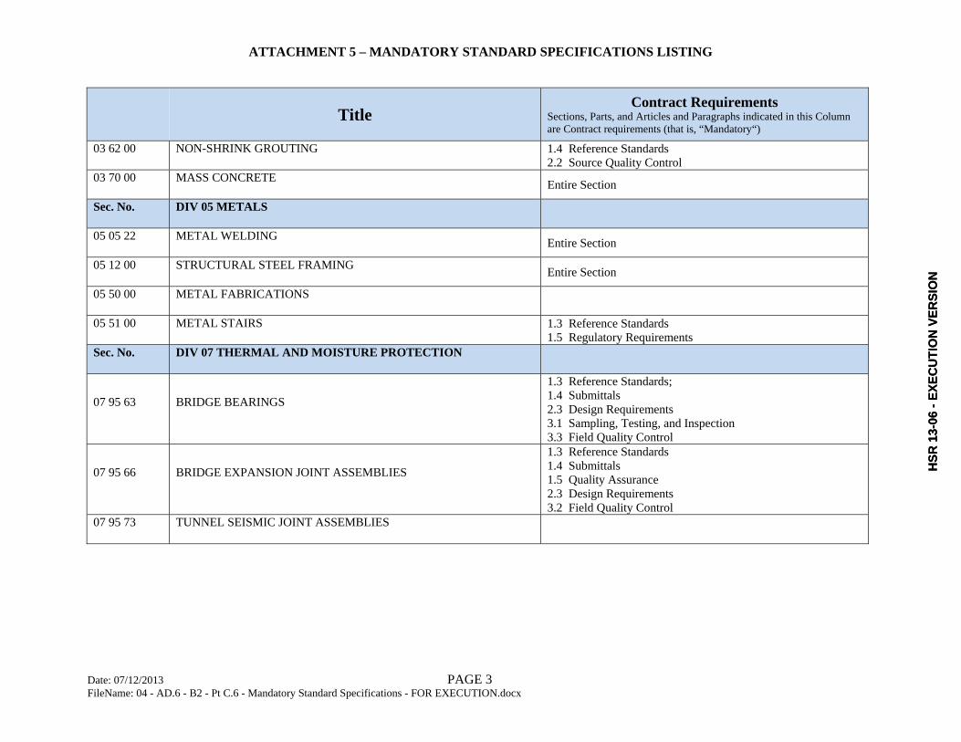
ATTACHMENT 5 – MANDATORY STANDARD SPECIFICATIONS LISTING
Date: 07/12/2013 PAGE 3 FileName: 04 - AD.6 - B2 - Pt C.6 - Mandatory Standard Specifications - FOR EXECUTION.docx
Title Contract Requirements
Sections, Parts, and Articles and Paragraphs indicated in this Column are Contract requirements (that is, “Mandatory“)
03 62 00 NON-SHRINK GROUTING 1.4 Reference Standards 2.2 Source Quality Control
03 70 00 MASS CONCRETE Entire Section
Sec. No. DIV 05 METALS
05 05 22 METAL WELDING Entire Section
05 12 00 STRUCTURAL STEEL FRAMING Entire Section
05 50 00 METAL FABRICATIONS
05 51 00 METAL STAIRS 1.3 Reference Standards 1.5 Regulatory Requirements
Sec. No. DIV 07 THERMAL AND MOISTURE PROTECTION
07 95 63 BRIDGE BEARINGS
1.3 Reference Standards; 1.4 Submittals 2.3 Design Requirements 3.1 Sampling, Testing, and Inspection 3.3 Field Quality Control
07 95 66 BRIDGE EXPANSION JOINT ASSEMBLIES
1.3 Reference Standards 1.4 Submittals 1.5 Quality Assurance 2.3 Design Requirements 3.2 Field Quality Control
07 95 73 TUNNEL SEISMIC JOINT ASSEMBLIES
HSR
13-
06 -
EXEC
UTI
ON
VER
SIO
NH
SR 1
3-06
- EX
ECU
TIO
N V
ERSI
ON

ATTACHMENT 5 – MANDATORY STANDARD SPECIFICATIONS LISTING
Date: 07/12/2013 PAGE 4 FileName: 04 - AD.6 - B2 - Pt C.6 - Mandatory Standard Specifications - FOR EXECUTION.docx
Title Contract Requirements
Sections, Parts, and Articles and Paragraphs indicated in this Column are Contract requirements (that is, “Mandatory“)
Sec. No. DIV 09 FINISHES
09 96 00 HIGH-PERFORMANCE COATINGS
1.3 Reference Standards; 1.5 Pre-Application Meetings 1.6 Submittals 1.7 Quality Assurance 1.8 Delivery, Storage, and Protection 2.1 Products 2.2 Shop Quality Control 3.5 Field Quality Control 3.8A. Interior Surfaces of Steel Structures
Sec. No. DIV 31 EARTHWORK
31 05 00 COMMON WORK RESULTS FOR EARTHWORK
1.4 Reference Standards 1.5 Classifications of Earthwork 1.6 Submittals 1.7 Regulatory Requirements 1.8 Quality Assurance 2.2 Fill and Backfill Materials – Specific Requirements 2.4 Source Quality Control 3.3C. Erosion Protection 3.11 Compaction 3.15 Field Quality Control
31 09 13 GEOTECHNICAL INSTRUMENTATION AND MONITORING Entire Section
31 11 00 CLEARING AND GRUBBING
Entire Section
31 23 19 DEWATERING
Entire Section
31 23 26 AGGREGATE DRAINAGE LAYER
31 35 00 SLOPE PROTECTION
31 35 33 TURF AND HYDROSEED SLOPE PROTECTION
HSR
13-
06 -
EXEC
UTI
ON
VER
SIO
NH
SR 1
3-06
- EX
ECU
TIO
N V
ERSI
ON

ATTACHMENT 5 – MANDATORY STANDARD SPECIFICATIONS LISTING
Date: 07/12/2013 PAGE 5 FileName: 04 - AD.6 - B2 - Pt C.6 - Mandatory Standard Specifications - FOR EXECUTION.docx
Title Contract Requirements
Sections, Parts, and Articles and Paragraphs indicated in this Column are Contract requirements (that is, “Mandatory“)
31 38 13 REINFORCED SLOPES AND EARTH STRUCTURES
1.4 Reference Standards 1.5 Submittals 1.7 Design Requirements 1.8 Qualifications of Supplier 1.9A. Delivery, Storage and Handling 2.1B.1 Soil Reinforcement 3.4 Field Quality Control
31 39 13 GROUND ANCHORS
1.4 Regulatory Requirements 1.5 Submittals 1.6 Quality Assurance 2.2 Design Requirements 3.3 Corrosion Protection 3.5 Field Quality Control – General 3.6 Stressing, Load Testing, and Acceptance of Ground
Anchors 31 50 13 TEMPORARY EXCAVATION SUPPORT AND PROTECTION
Entire Section
31 62 00 DRIVEN PILES
1.3 Reference Standards 1.4 Regulatory Requirements 1.5E. Submittal of PDF and CAPWAP Records 1.5F. Test Pile Test Reports 1.6 Quality Assurance Part 2 – Products 3.3 Indicator Piles and Test Piles 3.4 Axial Compression and Tension Load Tests 3.5 Lateral Load Tests 3.6 Dynamic Pile Testing 3.8 Installation Tolerances
31 63 29 DRILLED CONCRETE PIERS AND SHAFTS
1.3 Reference Standards 1.5 Submittals 1.6 Quality Assurance Part 2- Products 3.1 Tolerances 3.2 Method Test Shafts 3.3 Load Tests 3.8 Field Quality Control
HSR
13-
06 -
EXEC
UTI
ON
VER
SIO
NH
SR 1
3-06
- EX
ECU
TIO
N V
ERSI
ON

ATTACHMENT 5 – MANDATORY STANDARD SPECIFICATIONS LISTING
Date: 07/12/2013 PAGE 6 FileName: 04 - AD.6 - B2 - Pt C.6 - Mandatory Standard Specifications - FOR EXECUTION.docx
Title Contract Requirements
Sections, Parts, and Articles and Paragraphs indicated in this Column are Contract requirements (that is, “Mandatory“)
Sec. No. DIV 32 EXTERIOR IMPROVEMENTS
32 11 23 AGGREGATE BASE COURSES
32 31 13 CHAIN LINK FENCES AND GATES Entire Section
32 90 00 PLANTING
1.3 Reference Standards 1.4 System Description 1.5 Submittals 1.6 Quality Assurance 1.9 Site Conditions and Scheduling 1.10 Warranty 2.1 Plant Stock 2.5 Herbicides 2.15 Source Quality Control 2.16 Soil Analysis Report 3.5A. Herbicide and Pesticide Application 3.9A. and 3.9B. Drainage Test and Auger Holes 3.11 Inspection Prior to Commencement of Plant Establishment Period 3.13 Plant Establishment 3.14 Plant Establishment Final Inspection and Acceptance
Sec. No. DIV 33 UTILITIES
33 05 16 UTILITY STRUCTURES Entire Section
33 05 25 SUPPORT AND PROTECTION OF UTILITIES Entire Section
33 05 28 TRENCHING AND BACKFILLING FOR UTILITIES 2.2B. Detectable Tape 3.4E. Detectable Tape
33 05 33 RELOCATION OF EXISTING UTILITIES
33 11 00 WATER UTILITY DISTRIBUTION PIPING
HSR
13-
06 -
EXEC
UTI
ON
VER
SIO
NH
SR 1
3-06
- EX
ECU
TIO
N V
ERSI
ON

ATTACHMENT 5 – MANDATORY STANDARD SPECIFICATIONS LISTING
Date: 07/12/2013 PAGE 7 FileName: 04 - AD.6 - B2 - Pt C.6 - Mandatory Standard Specifications - FOR EXECUTION.docx
Title Contract Requirements
Sections, Parts, and Articles and Paragraphs indicated in this Column are Contract requirements (that is, “Mandatory“)
33 40 00 STORM DRAINAGE UTILITIES
33 46 00 SUBDRAINAGE
Sec. No. DIV 34 TRANSPORTATION
34 11 27 BALLASTED TRACK
End of List for Construction Package 1
HSR
13-
06 -
EXEC
UTI
ON
VER
SIO
NH
SR 1
3-06
- EX
ECU
TIO
N V
ERSI
ON

California High-Speed Train Project
Agreement No.: HSR 13-06
Scope of Work
ATTACHMENT 6 MANDATORY SPECIAL SPECIFICATIONS LISTING
HSR
13-
06 -
EXEC
UTI
ON
VER
SIO
NH
SR 1
3-06
- EX
ECU
TIO
N V
ERSI
ON

ATTACHMENT 6 – MANDATORY SPECIAL SPECIFICATIONS LISTING
Date: 07/12/2013 PAGE 1 FileName: 04 - AD.6 - B2 - Pt C.7 - Mandatory Special Specifications Listing - FOR EXECUTION.docx
Construction Package 1 - Special Specifications Listing of Sections, Articles, and Paragraphs that are Contract Requirements
Notes:1. Sections listed are for reference unless the entire Section is or parts of the Section (specific Parts, Articles, or Paragraphs)
are indicated as Contract requirements. Listing of Article or Paragraph includes all Paragraphs (and subparagraphs) under listed Article or Paragraph.
2. Wherever portion of a mandatory Special Specifications Section, Part, Article, or Paragraph refers to a portion of the Special Specifications listed as reference, the referenced portion shall be considered mandatory, as directly applicable to theportion of the Special Specifications included as a Contract requirement. Otherwise, the reference specifications section, by itself, it remains as reference.
TitleContract Requirements
Sections, Parts, and Articles and Paragraphs indicated in this Column are Contract requirements (that is, “Mandatory“)
Sec. No. DIV 02 TECHNICAL GENERAL REQUIREMENTS AND EXISTING CONDITIONS
02 01 11.23 RECONFIGURATION OF STANISLAUS AND TUOLUMNE STREETS
02 01 35.63 CALTRANS-IMPACTED FACILITIES Entire Section
02 01 35.66 CITY OF FRESNO-IMPACTED FACILITIES Entire Section
02 01 35.69 COUNTY OF FRESNO-IMPACTED FACILITIES
02 01 55.53 ACCESS TO LA TAPATIA Entire Section
Sec. No. DIV 03 CONCRETE
03 30 01 DESIGN AND CONSTRUCTION OF TRENCH STRUCTURES 1.6 Criteria
Sec. No. DIV 31 EARTHWORK
31 34 36 SOIL NAIL WALLS
31 66 16 SPECIAL FOUNDATIONS
HSR
13-
06 -
EXEC
UTI
ON
VER
SIO
NH
SR 1
3-06
- EX
ECU
TIO
N V
ERSI
ON

ATTACHMENT 6 – MANDATORY SPECIAL SPECIFICATIONS LISTING
Date: 07/12/2013 PAGE 2 FileName: 04 - AD.6 - B2 - Pt C.7 - Mandatory Special Specifications Listing - FOR EXECUTION.docx
Title Contract Requirements
Sections, Parts, and Articles and Paragraphs indicated in this Column are Contract requirements (that is, “Mandatory“)
31 74 10 JACKED BOX CONSTRUCTION 2.1 Criteria, Paragraphs A. through H, I, and K. through M.
Sec. No. DIV 33 UTILITIES
33 40 00 STORM DRAINAGE UTILITIES
Sec. No. DIV 35 WATERWAY AND MARINE CONSTRUCTION
35 40 00 WATERWAY CONSTRUCTION AND EQUIPMENT
End of List for Construction Package 1
HSR
13-
06 -
EXEC
UTI
ON
VER
SIO
NH
SR 1
3-06
- EX
ECU
TIO
N V
ERSI
ON

California High-Speed Train Project
Agreement No.: HSR 13-06
Scope of Work
ATTACHMENT 7 PROCEDURES FOR CONSTRUCTION-PHASE SUBMITTALS
HSR
13-
06 -
EXEC
UTI
ON
VER
SIO
NH
SR 1
3-06
- EX
ECU
TIO
N V
ERSI
ON

California High-Speed Train Project Agreement No.: HSR13-06
Page 1 of 3 EXECUTION VERSION Procedures for Construction Phase Submittals
Introduction
Construction‐phase submittals are defined as those submittals required under the final
Construction Specifications, such as shop drawings, product data, samples, certificates, test and
evaluation reports, manufacturersʹ instructions, source quality control submittals, field quality
control submittals, manufacturer reports, special procedure submittals, and qualification
statements.
Construction‐phase submittals also include delegated design submittals described in the
Construction Specifications which are typically drawings and calculations signed and sealed
by a fabricator or manufacturer’s engineer.
Construction‐phase submittals also include signed and sealed drawings and calculations for
temporary works such as shoring.
Construction‐phase submittals may include submittals for approval by the Authority and
others (Third Parties) and for “Statement of No Objection” (SONO) by the Authority
Representative. Refer to Verification, Validation, and Self‐Certification, Book 3.
1 General
This Appendix includes details for review of construction‐phase submittals by the Contractor
and the Contractor’s engineer. It also includes minimum requirements for distribution of
submittals, timing, changes, transmittal, and content.
2 Review
This Appendix assigns specific responsibilities for review of construction‐phase submittals to
the Contractor’s engineer. The Contractor’s review responsibilities designated herein facilitate
the Contractor’s engineer’s review and approval/acceptance. Refer to Book 3, Verification,
Validation, and Self‐Certification, for Contractor’s responsibilities for self‐certification.
The Contractor shall review construction‐phase submittals. At minimum, the Contractor’s
review shall cover the following items in order to facilitate the Contractor’s engineer’s review
and approval or acceptance:
Confirm that work is coordinated among trades, work is compatible with contiguous
products and other work, dimensions have been checked, and sufficient information is
available for systems integration.
Coordinate each submittal with the requirements of the Work and with the contents of other
submittals.
Ensure each submittal is complete with all relevant data required for review.
The Contractor shall submit construction‐phase submittals, except as otherwise specified, to the
Contractor’s engineer for review. Contractor’s engineer shall, at minimum, confirm that the
design intent is being met and work depicted in submittal is in compliance with Contract
HSR
13-
06 -
EXEC
UTI
ON
VER
SIO
NH
SR 1
3-06
- EX
ECU
TIO
N V
ERSI
ON

California High-Speed Train Project Agreement No.: HSR13-06
Page 2 of 3 EXECUTION VERSION Procedures for Construction Phase Submittals
requirements and code. Refer to Standard Specifications Section 02 01 00, Standard
Specifications General Statements, for definition of Contractor’s engineer.
For Approval: Submittals such as shop drawings, product data, samples, and manufacturer
or applicator qualifications shall be for the Contractor’s engineer’s approval, except as
otherwise specified.
For Information: Submittals such as calculations, test reports, certificates, manufacturer’s
instructions and field reports, and informational submittals shall be submitted for the
Contractor’s engineer’s information and review, except as otherwise specified.
For Information: Submittals such as drawings and calculations signed and sealed by a
professional engineer, including design delegated to a fabricator or manufacturer’s engineer
and design of temporary works, shall be submitted for the Contractor’s engineer’s
information and review, except as otherwise specified.
Contractor shall distribute copies of approved submittals and SONO’d submittals. At
minimum, distribute copies as follows:
Distribute to field office for use by Contractor’s field QC staff and others including
Authority representatives.
Distribute hard copies and make available electronically to the Authority to facilitate office
and field audits.
If acceptable to recipient of copies, submittals may be made available electronically in lieu of
hard copies.
Verification, Validation, and Self‐Certification shall be completed prior to construction or
installation of the work which is the subject of the submittal.
3 General Submittal Requirements
Review Stamp and Action Block Space: Include a five inch by five inch square blank space, in
the lower right corner, just above the title block, in which approval, requirement for
resubmittal, or SONO may be indicated.
Transmittal: Accompany submittals with a transmittal listing the following information, at
minimum. Coordinate this list with the Verification, Validation, and Self‐Certification
requirements and organize and expand the list as necessary:
Submittal title, number, and date, and revision number, as applicable.
Contract title and number.
Identification of drawing or page number, date, title, revision number, and sheet number, as
applicable.
Identification of products and samples: Description, model number, style number, lot
number, and place of origin as applicable.
Supplierʹs, manufacturerʹs, or subcontractorʹs name, address, and telephone number.
HSR
13-
06 -
EXEC
UTI
ON
VER
SIO
NH
SR 1
3-06
- EX
ECU
TIO
N V
ERSI
ON

California High-Speed Train Project Agreement No.: HSR13-06
Page 3 of 3 EXECUTION VERSION Procedures for Construction Phase Submittals
Engineer’s name, firm name, address, and phone number for drawings and calculations
signed and sealed by a Professional Engineer.
Subject identification including Construction Drawing and Construction Specifications
reference.
Identification of referenced standards, such as ASTM standard numbers.
Identification of location, structure number and name, and stationing, as applicable.
Identification of deviations from Contract Documents,
4 Specific Submittal Requirements
4.1 Shop Drawings Comply with the following requirements in regard to shop drawing submittals:
Drawings shall be limited to the following standard sizes in inches: Maximum size shall be
22 inches by 34 inches.
WIDTH (Vertical) LENGTH
(Horizontal)
WIDTH (Vertical) LENGTH
(Horizontal)
8 1/2 inches 11.0 inches 17.0 inches 22.0 inches
11.0 inches 8 1/2 inches 22.0 inches 34.0 inches
11.0 inches 17.0 inches
Shop drawings shall include details necessary for installation, maintenance, and repair of
components provided. Each drawing shall be updated to include all changes and be
upgraded to reflect the latest configuration and resubmitted.
Where required, prepare construction‐phase submittal drawings in accordance with the
CHSTP CADD Manual and CHSTP Plans Preparation Manual and submit drawings
electronically as well as hard copies. At minimum, shop drawings which will be utilized in
Operations and Maintenance Manuals and delegated design drawings shall be prepared in
accordance with these Manuals.
4.2 Product Data and Installation Instructions Comply with the following requirements in regard to product data and installation instructions
submittals:
Delete inapplicable information from product data such as catalog cuts and from
manufacturer’s printed installation instructions.
Supplement standard information with additional information applicable to the Contract.
Indicate dimensions, clearances, performance characteristics, capacities, wiring and other
diagrams, and controls.
HSR
13-
06 -
EXEC
UTI
ON
VER
SIO
NH
SR 1
3-06
- EX
ECU
TIO
N V
ERSI
ON

California High-Speed Train Project
Agreement No.: HSR 13-06
Scope of Work
ATTACHMENT 8 TECHNICAL CONTRACT SUBMITTAL LIST
HSR
13-
06 -
EXEC
UTI
ON
VER
SIO
NH
SR 1
3-06
- EX
ECU
TIO
N V
ERSI
ON

NO. DESIGNATIONSECTION NO./ CHAPTER
ARTICLE
1 Scope of Work 4.9.1 Design Baseline Report NTP + 180 days APPROVAL
2 Scope of Work 4.9.5Aesthetic Design and Review for Non‐Station Structure Report (as part of Design Baseline Report)
NTP + 180 days APPROVAL
3 Scope of Work 4.4 Design and Code Analysis Report Design Submittal SONO
4 Scope of Work 4.5 Safety and Security Certification Plan NTP + 60 days SONO
5 Scope of Work 4.8 Value Engineering Report After Approval of Design Baseline Report SONO
6 Scope of Work 4.9.2 Hydrology and Hydraulics Reports Design Submittal SONO
7 Scope of Work 4.9.3 Geotechnical Reports (GDR and GEDR) and all technical memoranda Design Submittal SONO
8 Scope of Work 4.9.3 GBR‐C Prior to beginning of construction APPROVAL9 Scope of Work 4.9.3 Geotechnical Investigation Plan (GIP) Prior to commencement of field work SONO
10 Scope of Work 4.9.4Type Selection Report, including Type Selection Memo, Major Reports, and Supporting Reports
After Approval of Design Baseline Report APPROVAL
11 Scope of Work 4.9.5 Structures Reports Design Submittal SONO12 Scope of Work 4.9.6 Certifiable Elements and Hazards Log Quarterly SONO
13 Scope of Work 4.9.7 Safety and Security Certification PackageWhen Certifiable Items Lists for each element
is completed for milestone paymentSONO
14 Scope of Work 4.9.8 Final Design Report Design Submittal SONO
15 Scope of Work 4.11Nominal 60% Construction Drawings (all sheets represented) and Specifications (outline)
Design Submittal (60% Design) SONO
16 Scope of Work 4.11Nominal 90% Construction Drawings (all sheets included) and Specifications (all specs included)
Design Submittal (90% Design) SONO
17 Scope of Work 4.11 Survey Reports (signed and sealed) ‐ Refer to Standard Specifications Design Submittal SONO
18 Scope of Work 4.12 Copy of Third‐Party Design Submittals and Approvals Design Submittal Per V&V Document (Book 3)
19 Scope of Work 4.13 Ready for Construction Submittals (signed and sealed) Prior to beginning of construction APPROVAL
20 Scope of Work 4.14 Design Variance RequestsAs needed, but Prior to incorporation into
RFCAPPROVAL
21 Scope of Work 4.15.1 Site‐Specific Health and Safety Plan NTP + 60 days SONO
22 Scope of Work 4.15.1 Site‐Specific Security Plan NTP + 60 days SONO
23 Scope of Work 4.15.2 Hazardous Materials Remediation PlanPrior to performing the hazardous material
removal workAPPROVAL
24 Scope of Work 4.15.4 Construction‐Phase Submittals ‐ Refer to Standard Specifications Per Standard Specifications Per Standard Specifications
SUBMITTAL TITLE/PACKAGE DUE DATESUBMITTAL TO AUTHORITY
(APPROVAL, SONO, INFORMATION)
Attachment 8 ‐ Technical Contract Submittal List
This list is intended to provide the Contractor with a summary of the Technical Contract Submittal requirements of the Contract Documents. Contractor shall use this list as the basis to prepare its list of submittal requirements per the Contract Documents.
CONTRACT REFERENCE (CP1)
Book 2, Part C.9 1 of 14
HSR
13-
06 -
EXEC
UTI
ON
VER
SIO
N

NO. DESIGNATIONSECTION NO./ CHAPTER
ARTICLESUBMITTAL TITLE/PACKAGE DUE DATE
SUBMITTAL TO AUTHORITY (APPROVAL, SONO, INFORMATION)
Attachment 8 ‐ Technical Contract Submittal List
This list is intended to provide the Contractor with a summary of the Technical Contract Submittal requirements of the Contract Documents. Contractor shall use this list as the basis to prepare its list of submittal requirements per the Contract Documents.
CONTRACT REFERENCE (CP1)
25 Scope of Work 4.15.5 As‐Builts (signed and sealed) SONO
26 Scope of Work 4.15.6 List of Mitigation Measures ‐ Refer to other Contract Requirements SONO
27 Scope of Work 5.1 Demolition Plan Prior to demolition work SONO28 Scope of Work 5.4 Trackbed Analysis Report Design Submittal SONO29 Scope of Work 5.17.1 Contractor RAM Program Plan (CRMP) ‐ Final NTP + 60 days SONO30 Scope of Work 5.17.1 Contractor RAM Program Plan (CRMP) ‐ Draft NTP + 90 days SONO31 Scope of Work 5.17.1 RAM Allocation Report Baseline Design Report Submittal SONO32 Scope of Work 5.17.1 Historical Product Maintainability Report (HPMR) Baseline Design Report Submittal SONO33 Scope of Work 5.17.1 Maintenance Manuals Final Design Report Submittal SONO34 Scope of Work 5.17.1 Reliability‐Centered Maintenance (RCM) Final Design Report Submittal SONO35 Scope of Work 5.17.1 Preventive Maintenance Analysis (PMA) Final Design Report Submittal ‐36 Scope of Work 5.17.1 Corrective Maintenance Analysis (CMA) Final Design Report Submittal ‐37 Scope of Work 5.17.1 Maintainability Demonstration Plan and Procedure (MDPP) Final Design Report Submittal SONO
38 Scope of Work 5.17.1 Maintainability Demonstration Test Report (MDTR)Before or with Substantial Completion
approval requestSONO
39 Scope of Work 5.18 Design Life and Durability Report Final Design Report Submittal SONO
40 Design Criteria Manual, Rev. 0 CH 7 ‐ Civil 7.8.1.5An alternative method of providing vehicular access to the trackside from the Authority facility
Baseline Design Report Submittal APPROVAL
41 Design Criteria Manual, Rev. 0 CH 7 ‐ Civil 7.8.4.3 Case 2 Concrete Barrier Wall Design Drawings Design Submittal APPROVAL
42 Design Criteria Manual, Rev. 0 CH 7 ‐ Civil 7.10.3Design drawings for temporary structures for the support and maintenance of surface traffic adjacent to and/or over the construction site
Construction Submittals SONO
43 Design Criteria Manual, Rev. 0 CH 9 ‐ Utilities 9.5.3Request for access to non‐CHST utilities from the Authority’s right‐of‐way
Design Submittal SONO
44 Design Criteria Manual, Rev. 0 CH 9 ‐ Utilities 9.5.5.4 Utility protection and monitoring plan (provided to the utility owner ) Construction Submittals INFORMATION
45 Design Criteria Manual, Rev. 0.1CH 10 ‐
Geotechnical10.4/ 10‐C.3
Qualifications of boring, in‐situ testing inspection staff as well as rock mapping staff and the blasting specialist
Design Submittal SONO
46 Design Criteria Manual, Rev. 0.1CH 10 ‐
Geotechnical10.6.4.3 Results of the Drivability Analysis Design Submittal SONO
47 Design Criteria Manual, Rev. 0.1CH 10 ‐
Geotechnical10.6.4.3 Indicator pile and testing results Construction Submittals SONO
48 Design Criteria Manual, Rev. 0.1CH 10 ‐
Geotechnical10.12.4.4 Verification of Numerical Program Design Submittal SONO
49 Design Criteria Manual, Rev. 0.1CH 10 ‐
Geotechnical10‐C.3 Rock Mapping Records Design Submittal INFORMATION
50 Design Criteria Manual, Rev. 0.1CH 10 ‐
Geotechnical10‐C.5.1 Blasting Plan Design Submittal SONO
Book 2, Part C.9 2 of 14
HSR
13-
06 -
EXEC
UTI
ON
VER
SIO
N
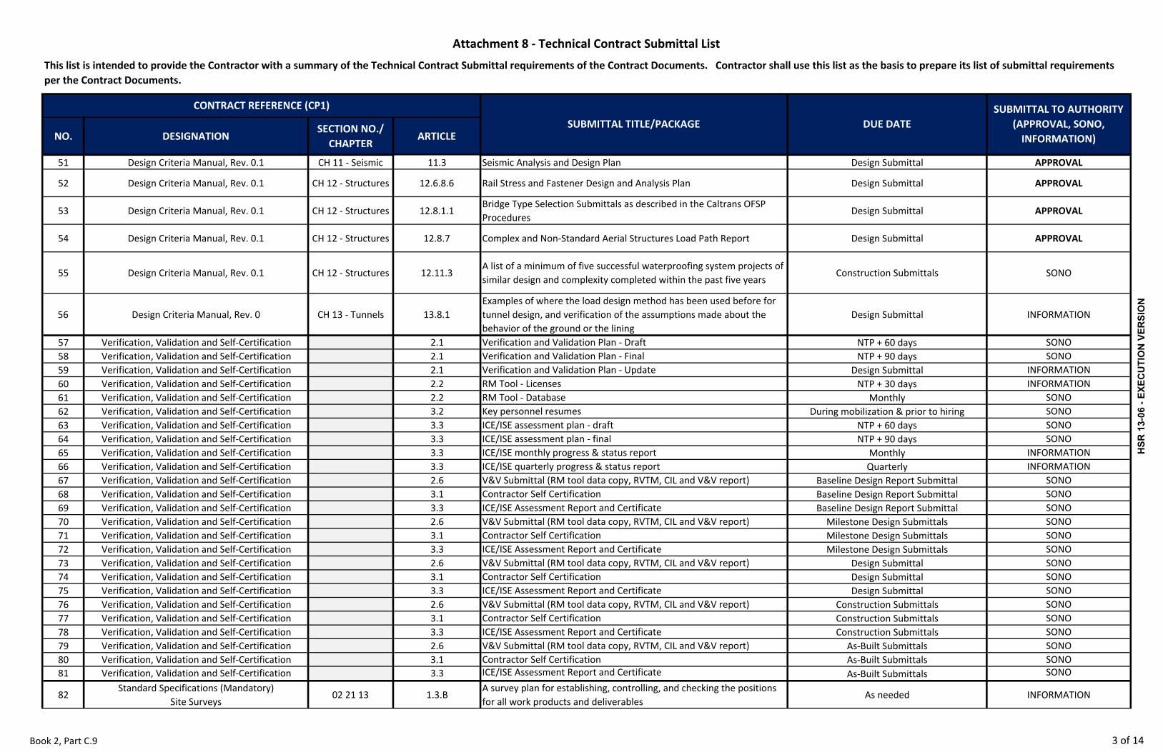
NO. DESIGNATIONSECTION NO./ CHAPTER
ARTICLESUBMITTAL TITLE/PACKAGE DUE DATE
SUBMITTAL TO AUTHORITY (APPROVAL, SONO, INFORMATION)
Attachment 8 ‐ Technical Contract Submittal List
This list is intended to provide the Contractor with a summary of the Technical Contract Submittal requirements of the Contract Documents. Contractor shall use this list as the basis to prepare its list of submittal requirements per the Contract Documents.
CONTRACT REFERENCE (CP1)
51 Design Criteria Manual, Rev. 0.1 CH 11 ‐ Seismic 11.3 Seismic Analysis and Design Plan Design Submittal APPROVAL
52 Design Criteria Manual, Rev. 0.1 CH 12 ‐ Structures 12.6.8.6 Rail Stress and Fastener Design and Analysis Plan Design Submittal APPROVAL
53 Design Criteria Manual, Rev. 0.1 CH 12 ‐ Structures 12.8.1.1Bridge Type Selection Submittals as described in the Caltrans OFSP Procedures
Design Submittal APPROVAL
54 Design Criteria Manual, Rev. 0.1 CH 12 ‐ Structures 12.8.7 Complex and Non‐Standard Aerial Structures Load Path Report Design Submittal APPROVAL
55 Design Criteria Manual, Rev. 0.1 CH 12 ‐ Structures 12.11.3A list of a minimum of five successful waterproofing system projects of similar design and complexity completed within the past five years
Construction Submittals SONO
56 Design Criteria Manual, Rev. 0 CH 13 ‐ Tunnels 13.8.1Examples of where the load design method has been used before for tunnel design, and verification of the assumptions made about the behavior of the ground or the lining
Design Submittal INFORMATION
57 Verification, Validation and Self‐Certification 2.1 Verification and Validation Plan ‐ Draft NTP + 60 days SONO58 Verification, Validation and Self‐Certification 2.1 Verification and Validation Plan ‐ Final NTP + 90 days SONO59 Verification, Validation and Self‐Certification 2.1 Verification and Validation Plan ‐ Update Design Submittal INFORMATION60 Verification, Validation and Self‐Certification 2.2 RM Tool ‐ Licenses NTP + 30 days INFORMATION61 Verification, Validation and Self‐Certification 2.2 RM Tool ‐ Database Monthly SONO62 Verification, Validation and Self‐Certification 3.2 Key personnel resumes During mobilization & prior to hiring SONO63 Verification, Validation and Self‐Certification 3.3 ICE/ISE assessment plan ‐ draft NTP + 60 days SONO64 Verification, Validation and Self‐Certification 3.3 ICE/ISE assessment plan ‐ final NTP + 90 days SONO65 Verification, Validation and Self‐Certification 3.3 ICE/ISE monthly progress & status report Monthly INFORMATION66 Verification, Validation and Self‐Certification 3.3 ICE/ISE quarterly progress & status report Quarterly INFORMATION67 Verification, Validation and Self‐Certification 2.6 V&V Submittal (RM tool data copy, RVTM, CIL and V&V report) Baseline Design Report Submittal SONO68 Verification, Validation and Self‐Certification 3.1 Contractor Self Certification Baseline Design Report Submittal SONO69 Verification, Validation and Self‐Certification 3.3 ICE/ISE Assessment Report and Certificate Baseline Design Report Submittal SONO70 Verification, Validation and Self‐Certification 2.6 V&V Submittal (RM tool data copy, RVTM, CIL and V&V report) Milestone Design Submittals SONO71 Verification, Validation and Self‐Certification 3.1 Contractor Self Certification Milestone Design Submittals SONO72 Verification, Validation and Self‐Certification 3.3 ICE/ISE Assessment Report and Certificate Milestone Design Submittals SONO73 Verification, Validation and Self‐Certification 2.6 V&V Submittal (RM tool data copy, RVTM, CIL and V&V report) Design Submittal SONO74 Verification, Validation and Self‐Certification 3.1 Contractor Self Certification Design Submittal SONO75 Verification, Validation and Self‐Certification 3.3 ICE/ISE Assessment Report and Certificate Design Submittal SONO76 Verification, Validation and Self‐Certification 2.6 V&V Submittal (RM tool data copy, RVTM, CIL and V&V report) Construction Submittals SONO77 Verification, Validation and Self‐Certification 3.1 Contractor Self Certification Construction Submittals SONO78 Verification, Validation and Self‐Certification 3.3 ICE/ISE Assessment Report and Certificate Construction Submittals SONO79 Verification, Validation and Self‐Certification 2.6 V&V Submittal (RM tool data copy, RVTM, CIL and V&V report) As‐Built Submittals SONO80 Verification, Validation and Self‐Certification 3.1 Contractor Self Certification As‐Built Submittals SONO81 Verification, Validation and Self‐Certification 3.3 ICE/ISE Assessment Report and Certificate As‐Built Submittals SONO
82Standard Specifications (Mandatory)
Site Surveys02 21 13 1.3.B
A survey plan for establishing, controlling, and checking the positions for all work products and deliverables
As needed INFORMATION
Book 2, Part C.9 3 of 14
HSR
13-
06 -
EXEC
UTI
ON
VER
SIO
N
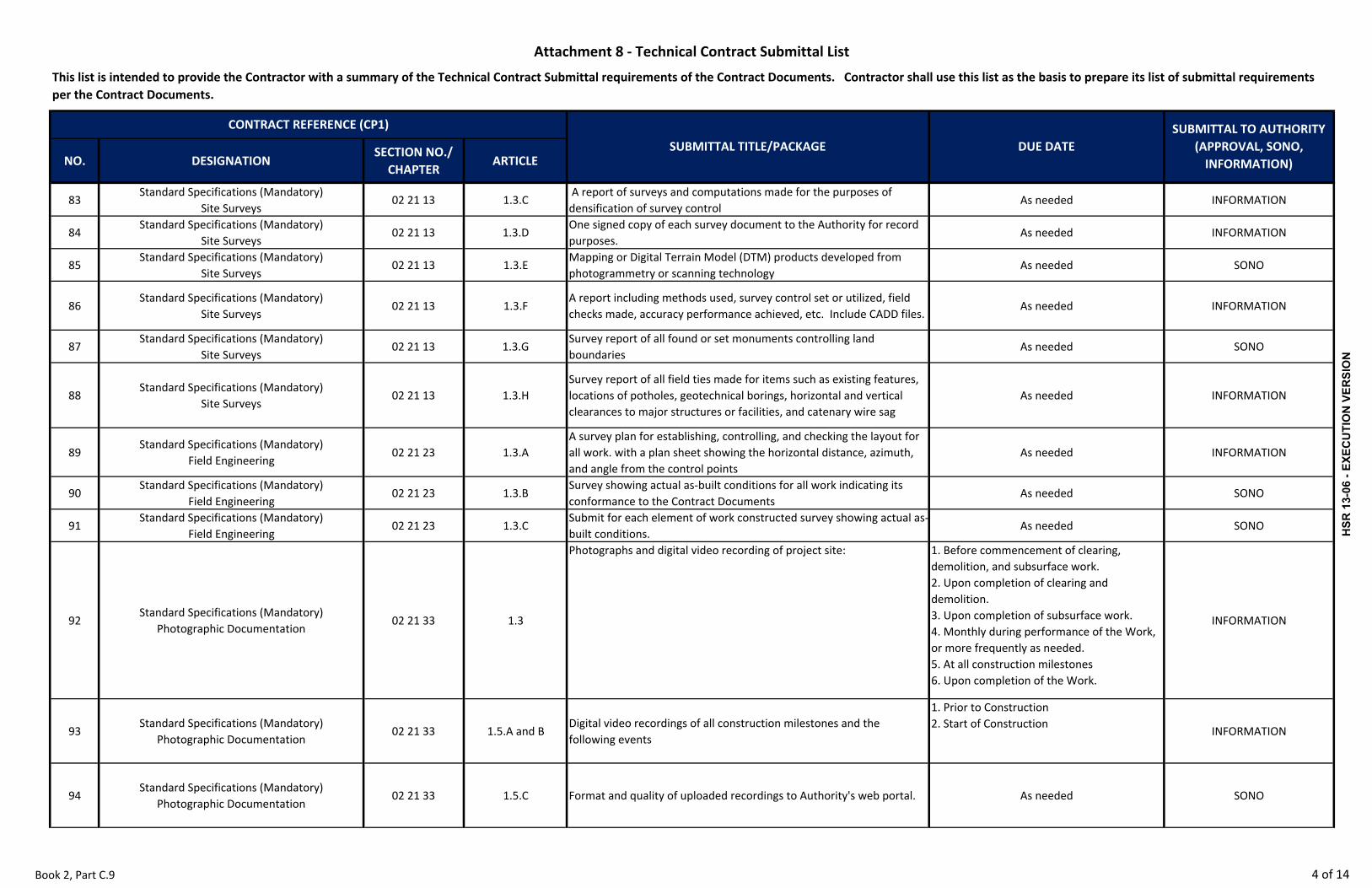
NO. DESIGNATIONSECTION NO./ CHAPTER
ARTICLESUBMITTAL TITLE/PACKAGE DUE DATE
SUBMITTAL TO AUTHORITY (APPROVAL, SONO, INFORMATION)
Attachment 8 ‐ Technical Contract Submittal List
This list is intended to provide the Contractor with a summary of the Technical Contract Submittal requirements of the Contract Documents. Contractor shall use this list as the basis to prepare its list of submittal requirements per the Contract Documents.
CONTRACT REFERENCE (CP1)
83Standard Specifications (Mandatory)
Site Surveys02 21 13 1.3.C
A report of surveys and computations made for the purposes of densification of survey control
As needed INFORMATION
84Standard Specifications (Mandatory)
Site Surveys02 21 13 1.3.D
One signed copy of each survey document to the Authority for record purposes.
As needed INFORMATION
85Standard Specifications (Mandatory)
Site Surveys02 21 13 1.3.E
Mapping or Digital Terrain Model (DTM) products developed from photogrammetry or scanning technology
As needed SONO
86Standard Specifications (Mandatory)
Site Surveys02 21 13 1.3.F
A report including methods used, survey control set or utilized, field checks made, accuracy performance achieved, etc. Include CADD files.
As needed INFORMATION
87Standard Specifications (Mandatory)
Site Surveys02 21 13 1.3.G
Survey report of all found or set monuments controlling land boundaries
As needed SONO
88Standard Specifications (Mandatory)
Site Surveys02 21 13 1.3.H
Survey report of all field ties made for items such as existing features, locations of potholes, geotechnical borings, horizontal and vertical clearances to major structures or facilities, and catenary wire sag
As needed INFORMATION
89Standard Specifications (Mandatory)
Field Engineering02 21 23 1.3.A
A survey plan for establishing, controlling, and checking the layout for all work. with a plan sheet showing the horizontal distance, azimuth, and angle from the control points
As needed INFORMATION
90Standard Specifications (Mandatory)
Field Engineering02 21 23 1.3.B
Survey showing actual as‐built conditions for all work indicating its conformance to the Contract Documents
As needed SONO
91Standard Specifications (Mandatory)
Field Engineering02 21 23 1.3.C
Submit for each element of work constructed survey showing actual as‐built conditions.
As needed SONO
92Standard Specifications (Mandatory)
Photographic Documentation02 21 33 1.3
Photographs and digital video recording of project site: 1. Before commencement of clearing, demolition, and subsurface work.2. Upon completion of clearing and demolition.3. Upon completion of subsurface work.4. Monthly during performance of the Work, or more frequently as needed.5. At all construction milestones 6. Upon completion of the Work.
INFORMATION
93Standard Specifications (Mandatory)
Photographic Documentation02 21 33 1.5.A and B
Digital video recordings of all construction milestones and the following events
1. Prior to Construction2. Start of Construction
INFORMATION
94Standard Specifications (Mandatory)
Photographic Documentation02 21 33 1.5.C Format and quality of uploaded recordings to Authority's web portal. As needed SONO
Book 2, Part C.9 4 of 14
HSR
13-
06 -
EXEC
UTI
ON
VER
SIO
N

NO. DESIGNATIONSECTION NO./ CHAPTER
ARTICLESUBMITTAL TITLE/PACKAGE DUE DATE
SUBMITTAL TO AUTHORITY (APPROVAL, SONO, INFORMATION)
Attachment 8 ‐ Technical Contract Submittal List
This list is intended to provide the Contractor with a summary of the Technical Contract Submittal requirements of the Contract Documents. Contractor shall use this list as the basis to prepare its list of submittal requirements per the Contract Documents.
CONTRACT REFERENCE (CP1)
95Standard Specifications (Mandatory)
Photographic Documentation02 21 33 1.6.A Color aerial photographs of the entire job site As needed INFORMATION
96Standard Specifications (Mandatory)
Photographic Documentation02 21 33 1.8.A Aerial photographs of the entire Jobsite As needed INFORMATION
97Standard Specifications (Mandatory)
Existing Conditions Assessment02 22 00 1.3.A Preconstruction Condition Survey Report. As needed INFORMATION
98Standard Specifications (Mandatory)
Portland Cement Concrete03 05 15 1.6.A Concrete Mix Designs As needed INFORMATION
99Standard Specifications (Mandatory)
Portland Cement Concrete03 05 15 1.6.B Manufacturer's product data for proposed concrete admixtures As needed SONO
100Standard Specifications (Mandatory)
Portland Cement Concrete03 05 15 1.6.C Aggregate source As needed SONO
101Standard Specifications (Mandatory)
Portland Cement Concrete03 05 15 1.6.D
Affidavits/Certificates for cement, aggregate, supplementary cementitious materials, and admixtures
As needed INFORMATION
102Standard Specifications (Mandatory)
Portland Cement Concrete03 05 15 1.6.E Batch Tickets As needed ‐
103Standard Specifications (Mandatory)
Portland Cement Concrete03 05 15 1.6.F
Name, address, and telephone number of the laboratory, agency, mill, or ready‐mix plant
As needed INFORMATION
104Standard Specifications (Mandatory)
Portland Cement Concrete03 05 15 2.1.C.1 Source of Special Aggregates As needed SONO
105Standard Specifications (Mandatory)
Portland Cement Concrete03 05 15 2.1.D Concrete Admixture and Cementitious Materials As needed SONO
106Standard Specifications (Mandatory)
Prestressed Concrete03 05 18 1.6.A Test results and certifications re. Post‐Tensioning System As needed SONO
107Standard Specifications (Mandatory)
Prestressed Concrete03 05 18 1.6.B Shop drawings As needed INFORMATION
108Standard Specifications (Mandatory)
Prestressed Concrete03 05 18 1.6.C Safety Plan As needed INFORMATION
109Standard Specifications (Mandatory)
Prestressed Concrete03 05 18 1.6.D Grouting Operations Plan As needed INFORMATION
110Standard Specifications (Mandatory)
Prestressed Concrete03 05 18 1.6.E Product Data As needed SONO
111Standard Specifications (Mandatory)
Prestressed Concrete03 05 18 1.6.F Certification As needed INFORMATION
112Standard Specifications (Mandatory)
Prestressed Concrete03 05 18 1.6.G Grouting Report Within 72 hours of each grouting operation INFORMATION
113Standard Specifications (Mandatory)
Prestressed Concrete03 05 18 1.6.H Field Test Reports As needed INFORMATION
Book 2, Part C.9 5 of 14
HSR
13-
06 -
EXEC
UTI
ON
VER
SIO
N

NO. DESIGNATIONSECTION NO./ CHAPTER
ARTICLESUBMITTAL TITLE/PACKAGE DUE DATE
SUBMITTAL TO AUTHORITY (APPROVAL, SONO, INFORMATION)
Attachment 8 ‐ Technical Contract Submittal List
This list is intended to provide the Contractor with a summary of the Technical Contract Submittal requirements of the Contract Documents. Contractor shall use this list as the basis to prepare its list of submittal requirements per the Contract Documents.
CONTRACT REFERENCE (CP1)
114Standard Specifications (Mandatory)
Prestressed Concrete03 05 18 1.6.I Elastomeric Coating Applicator Qualifications As needed INFORMATION
115Standard Specifications (Mandatory)
Prestressed Concrete03 05 18 1.6.J Prestressing Firm Qualifications As needed SONO
116Standard Specifications (Mandatory)
Prestressed Concrete03 05 18 1.7.C Certification of independent laboratory if outside the U.S. As needed SONO
117Standard Specifications (Mandatory)
Falsework03 11 14 1.4.A Shop drawings and supporting calculations for falsework As needed INFORMATION
118Standard Specifications (Mandatory)
Falsework03 11 14 1.4.B Form design and materials data As needed INFORMATION
119Standard Specifications (Mandatory)
Falsework03 11 14 1.4.C Falsework lighting plan As needed INFORMATION
120Standard Specifications (Mandatory)
Concrete Anchors03 15 23 1.6.A Product Data As needed INFORMATION
121Standard Specifications (Mandatory)
Concrete Anchors03 15 23 1.6.B Samples As needed INFORMATION
122Standard Specifications (Mandatory)
Concrete Anchors03 15 23 1.6.C Certified Test Reports As needed INFORMATION
123Standard Specifications (Mandatory)
Concrete Anchors03 15 23 1.6.D Installer Qualifications and Procedures As needed INFORMATION
124Standard Specifications (Mandatory)
Concrete Anchors03 15 23 1.6.E Installation and Field Quality Control Methods As needed INFORMATION
125Standard Specifications (Mandatory)
Concrete Anchors03 15 23 1.6.F Certificates As needed INFORMATION
126Standard Specifications (Mandatory)
Concrete Anchors03 15 23 1.6.G installation and Testing Methods As needed INFORMATION
127Standard Specifications (Mandatory)
Concrete Anchors03 15 23 1.6.H Documentation As needed INFORMATION
128Standard Specifications (Mandatory)
Concrete Anchors03 15 23 1.6.H.4 Failed Anchor Documentation As needed SONO
129Standard Specifications (Mandatory)
Concrete Anchors03 15 23 1.6.I Record Documents As needed INFORMATION
130Standard Specifications (Mandatory)
Concrete Reinforcing03 20 00 1.4.A Shop drawings for all reinforcing steel As needed INFORMATION
131Standard Specifications (Mandatory)
Concrete Reinforcing03 20 00 1.4.B Product Data As needed INFORMATION
132Standard Specifications (Mandatory)
Concrete Reinforcing03 20 00 1.4.C Certificates As needed INFORMATION
133Standard Specifications (Mandatory)
Cast‐In‐Place Concrete03 30 00 1.4.A Shop Drawings As needed INFORMATION
Book 2, Part C.9 6 of 14
HSR
13-
06 -
EXEC
UTI
ON
VER
SIO
N

NO. DESIGNATIONSECTION NO./ CHAPTER
ARTICLESUBMITTAL TITLE/PACKAGE DUE DATE
SUBMITTAL TO AUTHORITY (APPROVAL, SONO, INFORMATION)
Attachment 8 ‐ Technical Contract Submittal List
This list is intended to provide the Contractor with a summary of the Technical Contract Submittal requirements of the Contract Documents. Contractor shall use this list as the basis to prepare its list of submittal requirements per the Contract Documents.
CONTRACT REFERENCE (CP1)
134Standard Specifications (Mandatory)
Cast‐In‐Place Concrete03 30 00 1.4.B Product Data As needed INFORMATION
135Standard Specifications (Mandatory)
Cast‐In‐Place Concrete03 30 00 1.4.C Records and Reports As needed INFORMATION
136Standard Specifications (Mandatory)
Cast‐In‐Place Concrete03 30 00 1.5.C.1 Site Mock‐ups As needed SONO
137Standard Specifications (Mandatory)
Concrete Finishing03 35 00 1.5.C and D Site Mock‐ups As needed SONO
138Standard Specifications (Mandatory)
Precast Concrete03 40 00 1.5.A Shop Drawings As needed INFORMATION
139Standard Specifications (Mandatory)
Precast Concrete03 40 00 1.5.B Product Data As needed INFORMATION
140Standard Specifications (Mandatory)
Precast Concrete03 40 00 1.5.C Samples As needed INFORMATION
141Standard Specifications (Mandatory)
Precast Concrete03 40 00 1.5.D Certificates As needed INFORMATION
142Standard Specifications (Mandatory)
Precast Concrete03 40 00 1.6.E Mock‐ups As needed SONO
143Standard Specifications (Mandatory)
Precast Concrete03 40 00 1.6.F Control Samples As needed SONO
144Standard Specifications (Mandatory)
Precast Concrete Segmental Construction03 43 00 1.6.A
Shop drawings and calculations for precast concrete segmental construction, Casting manual, Erection Manual, etc.
As needed SONO
145Standard Specifications (Mandatory)
Precast Concrete Segmental Construction03 43 00 1.6.B Qualifications of personnel As needed INFORMATION
146Standard Specifications (Mandatory)
Precast Concrete Segmental Construction03 43 00 1.6.C Record of Jointing As needed INFORMATION
147Standard Specifications (Mandatory)
Mass Concrete03 70 00 1.4.B Gradation of Aggregates As needed INFORMATION
148Standard Specifications (Mandatory)
Mass Concrete03 70 00 1.4.C Temperature Control Plan As needed INFORMATION
149Standard Specifications (Mandatory)
Mass Concrete03 70 00 1.4.D Repairs methods or corrective actions As needed INFORMATION
150Standard Specifications (Mandatory)
Mass Concrete03 70 00 1.4.E Layout of cooling pipe system if used As needed INFORMATION
151Standard Specifications (Mandatory)
Mass Concrete03 70 00 1.4.F Concrete Placement Plan As needed INFORMATION
152Standard Specifications (Mandatory)
Mass Concrete03 70 00 1.4.G Daily reports of temperature monitoring of concrete As needed INFORMATION
153Standard Specifications (Mandatory)
Metal Welding05 05 22 1.5.A Shop Drawings As needed INFORMATION
Book 2, Part C.9 7 of 14
HSR
13-
06 -
EXEC
UTI
ON
VER
SIO
N

NO. DESIGNATIONSECTION NO./ CHAPTER
ARTICLESUBMITTAL TITLE/PACKAGE DUE DATE
SUBMITTAL TO AUTHORITY (APPROVAL, SONO, INFORMATION)
Attachment 8 ‐ Technical Contract Submittal List
This list is intended to provide the Contractor with a summary of the Technical Contract Submittal requirements of the Contract Documents. Contractor shall use this list as the basis to prepare its list of submittal requirements per the Contract Documents.
CONTRACT REFERENCE (CP1)
154Standard Specifications (Mandatory)
Metal Welding05 05 22 1.5.B Welder Qualifications As needed INFORMATION
155Standard Specifications (Mandatory)
Metal Welding05 05 22 1.5.C Welding Procedure Specifications (WPS) As needed INFORMATION
156Standard Specifications (Mandatory)
Metal Welding05 05 22 1.5.D Welding Records and Data As needed INFORMATION
157Standard Specifications (Mandatory)
Metal Welding05 05 22 1.5.E Mill Certificates As needed INFORMATION
158Standard Specifications (Mandatory)
Structural Steel Framing05 12 00 1.4.A Shop drawings As needed INFORMATION
159Standard Specifications (Mandatory)
Structural Steel Framing05 12 00 1.4.B Product data As needed INFORMATION
160Standard Specifications (Mandatory)
Structural Steel Framing05 12 00 1.4.C Mill Test Reports As needed INFORMATION
161Standard Specifications (Mandatory)
Structural Steel Framing05 12 00 1.4.D Fabrication Qualifications As needed INFORMATION
162Standard Specifications (Mandatory)
Structural Steel Framing05 12 00 1.4.E High‐Strength Bolted Connection Reports As needed INFORMATION
163Standard Specifications (Mandatory)
Structural Steel Framing05 12 00 1.4.F Welding Records and Data As needed INFORMATION
164Standard Specifications (Mandatory)
Bridge Bearings07 95 63 1.4.A Shop drawings As needed INFORMATION
165Standard Specifications (Mandatory)
Bridge Bearings07 95 63 1.4.B Calculations As needed INFORMATION
166Standard Specifications (Mandatory)
Bridge Bearings07 95 63 1.4.C Weld procedures As needed INFORMATION
167Standard Specifications (Mandatory)
Bridge Bearings07 95 63 1.4.D Product Data As needed SONO
168Standard Specifications (Mandatory)
Bridge Bearings07 95 63 1.4.E Certificates of Compliance As needed INFORMATION
169Standard Specifications (Mandatory)
Bridge Bearings07 95 63 1.4.F Factory Quality Control Test Procedures and Results As needed INFORMATION
170Standard Specifications (Mandatory)Bridge Expansion Joint Assemblies
07 95 66 1.4.A Product data and shop drawings for the expansion joint system As needed SONO
171Standard Specifications (Mandatory)Bridge Expansion Joint Assemblies
07 95 66 1.4.B Certifications of compliance As needed INFORMATION
172Standard Specifications (Mandatory)Bridge Expansion Joint Assemblies
07 95 66 1.4.C Fire rating certification As needed INFORMATION
173Standard Specifications (Mandatory)
High‐Performance Coatings09 96 00 1.6.A Product Data and Manufacturer's Certification As needed SONO
Book 2, Part C.9 8 of 14
HSR
13-
06 -
EXEC
UTI
ON
VER
SIO
N
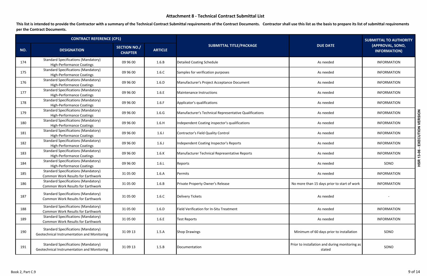
NO. DESIGNATIONSECTION NO./ CHAPTER
ARTICLESUBMITTAL TITLE/PACKAGE DUE DATE
SUBMITTAL TO AUTHORITY (APPROVAL, SONO, INFORMATION)
Attachment 8 ‐ Technical Contract Submittal List
This list is intended to provide the Contractor with a summary of the Technical Contract Submittal requirements of the Contract Documents. Contractor shall use this list as the basis to prepare its list of submittal requirements per the Contract Documents.
CONTRACT REFERENCE (CP1)
174Standard Specifications (Mandatory)
High‐Performance Coatings09 96 00 1.6.B Detailed Coating Schedule As needed INFORMATION
175Standard Specifications (Mandatory)
High‐Performance Coatings09 96 00 1.6.C Samples for verification purposes As needed INFORMATION
176Standard Specifications (Mandatory)
High‐Performance Coatings09 96 00 1.6.D Manufacturer's Project Acceptance Document As needed INFORMATION
177Standard Specifications (Mandatory)
High‐Performance Coatings09 96 00 1.6.E Maintenance Instructions As needed INFORMATION
178Standard Specifications (Mandatory)
High‐Performance Coatings09 96 00 1.6.F Applicator's qualifications As needed INFORMATION
179Standard Specifications (Mandatory)
High‐Performance Coatings09 96 00 1.6.G Manufacturer's Technical Representative Qualifications As needed INFORMATION
180Standard Specifications (Mandatory)
High‐Performance Coatings09 96 00 1.6.H Independent Coating inspector's qualifications As needed INFORMATION
181Standard Specifications (Mandatory)
High‐Performance Coatings09 96 00 1.6.I Contractor's Field Quality Control As needed INFORMATION
182Standard Specifications (Mandatory)
High‐Performance Coatings09 96 00 1.6.J Independent Coating Inspector's Reports As needed INFORMATION
183Standard Specifications (Mandatory)
High‐Performance Coatings09 96 00 1.6.K Manufacturer Technical Representative Reports As needed INFORMATION
184Standard Specifications (Mandatory)
High‐Performance Coatings09 96 00 1.6.L Reports As needed SONO
185Standard Specifications (Mandatory)Common Work Results for Earthwork
31 05 00 1.6.A Permits As needed INFORMATION
186Standard Specifications (Mandatory)Common Work Results for Earthwork
31 05 00 1.6.B Private Property Owner's Release No more than 15 days prior to start of work INFORMATION
187Standard Specifications (Mandatory)Common Work Results for Earthwork
31 05 00 1.6.C Delivery Tickets As needed ‐
188Standard Specifications (Mandatory)Common Work Results for Earthwork
31 05 00 1.6.D Field Verification for In‐Situ Treatment As needed INFORMATION
189Standard Specifications (Mandatory)Common Work Results for Earthwork
31 05 00 1.6.E Test Reports As needed INFORMATION
190Standard Specifications (Mandatory)
Geotechnical Instrumentation and Monitoring31 09 13 1.5.A Shop Drawings Minimum of 60 days prior to installation SONO
191Standard Specifications (Mandatory)
Geotechnical Instrumentation and Monitoring31 09 13 1.5.B Documentation
Prior to installation and during monitoring as stated
SONO
Book 2, Part C.9 9 of 14
HSR
13-
06 -
EXEC
UTI
ON
VER
SIO
N

NO. DESIGNATIONSECTION NO./ CHAPTER
ARTICLESUBMITTAL TITLE/PACKAGE DUE DATE
SUBMITTAL TO AUTHORITY (APPROVAL, SONO, INFORMATION)
Attachment 8 ‐ Technical Contract Submittal List
This list is intended to provide the Contractor with a summary of the Technical Contract Submittal requirements of the Contract Documents. Contractor shall use this list as the basis to prepare its list of submittal requirements per the Contract Documents.
CONTRACT REFERENCE (CP1)
192Standard Specifications (Mandatory)
Geotechnical Instrumentation and Monitoring31 09 13 1.5.C Certifications Minimum of 60 days prior to installation SONO
193Standard Specifications (Mandatory)
Geotechnical Instrumentation and Monitoring31 09 13 1.5.D Monitoring Documentation
Within 12 hours after monitoring any instrument
SONO
194Standard Specifications (Mandatory)
Geotechnical Instrumentation and Monitoring31 09 13 1.5.E Mix Designs Prior to start of work SONO
195Standard Specifications (Mandatory)
Geotechnical Instrumentation and Monitoring31 09 13 1.5.F Closure Report Upon removal of instrumentation SONO
196Standard Specifications (Mandatory)
Geotechnical Instrumentation and Monitoring31 09 13
1.4 F. thru I, L and M.
Design information as required by referenced paragraphs including all proposed remedial measures.
Minimum of 60 days prior to installation APPROVAL
197Standard Specifications (Mandatory)
Clearing and Grubbing31 11 00 1.4.A Utility Severance Certificates As needed INFORMATION
198Standard Specifications (Mandatory)
Dewatering31 23 19 1.5A Pre‐construction surveys As needed INFORMATION
199Standard Specifications (Mandatory)
Dewatering31 23 19 1.5B
Procedures for detection of movement and records of movement detection
As needed SONO
200Standard Specifications (Mandatory)
Dewatering31 23 19 1.5C Shop Drawings and design data of dewatering system Prior to installation of dewatering system INFORMATION
201Standard Specifications (Mandatory)
Dewatering31 23 19 1.5D Copies of permits required for performing the work of this Section As needed SONO
202Standard Specifications (Mandatory)
Dewatering31 23 19 1.5E Records of monitoring and movement One day after the reading SONO
203Standard Specifications (Mandatory)
Dewatering31 23 19 1.5F Observation Records and Water Quality test results During dewatering operation INFORMATION
204Standard Specifications (Mandatory)
Reinforced Slopes and Earth Structures31 38 13 1.5.A Product Data INFORMATION
205Standard Specifications (Mandatory)
Reinforced Slopes and Earth Structures31 38 13 1.B.B Design Submittal
Minimum of 60 days prior to start of earth structure system construction
APPROVAL
206Standard Specifications (Mandatory)
Reinforced Slopes and Earth Structures31 38 13 1.5.C Shop drawings and calculations As needed INFORMATION
207Standard Specifications (Mandatory)
Reinforced Slopes and Earth Structures31 38 13 1.5.D Record of drawings As needed INFORMATION
208Standard Specifications (Mandatory)
Reinforced Slopes and Earth Structures31 38 13 1.5.E Certificates of Compliance As needed INFORMATION
209Standard Specifications (Mandatory)
Reinforced Slopes and Earth Structures31 38 13 1.5.F Field Construction Manual As needed INFORMATION
Book 2, Part C.9 10 of 14
HSR
13-
06 -
EXEC
UTI
ON
VER
SIO
N

NO. DESIGNATIONSECTION NO./ CHAPTER
ARTICLESUBMITTAL TITLE/PACKAGE DUE DATE
SUBMITTAL TO AUTHORITY (APPROVAL, SONO, INFORMATION)
Attachment 8 ‐ Technical Contract Submittal List
This list is intended to provide the Contractor with a summary of the Technical Contract Submittal requirements of the Contract Documents. Contractor shall use this list as the basis to prepare its list of submittal requirements per the Contract Documents.
CONTRACT REFERENCE (CP1)
210Standard Specifications (Mandatory)
Reinforced Slopes and Earth Structures31 38 13 1.5.G Qualifications of Independent Testing Agency As needed INFORMATION
211Standard Specifications (Mandatory)
Ground Anchors31 39 13 1.5.A
Calculations for design of the tendons, unbonded lengths, bonded lengths, bearing plates, bearing stiffeners, and wedge plates
As needed INFORMATION
212Standard Specifications (Mandatory)
Ground Anchors31 39 13 1.5.B Shop Drawings As needed INFORMATION
213Standard Specifications (Mandatory)
Ground Anchors31 39 13 1.5.C Manufacturer’s Instructions As needed INFORMATION
214Standard Specifications (Mandatory)
Ground Anchors31 39 13 1.5.D Grout mix design As needed INFORMATION
215Standard Specifications (Mandatory)
Ground Anchors31 39 13 1.5.E Mill test reports for prestressing steel and bearing plate steel As needed INFORMATION
216Standard Specifications (Mandatory)
Ground Anchors31 39 13 1.5.F
Calibration data for each test jack, load cell, primary pressure gage, and reference pressure gage to be used
As needed INFORMATION
217Standard Specifications (Mandatory)
Ground Anchors31 39 13 1.5.G Grouting records As needed INFORMATION
218Standard Specifications (Mandatory)
Ground Anchors31 39 13 1.5.H Test data and results for all testing required As needed SONO
219Standard Specifications (Mandatory)
Ground Anchors31 39 13 1.5.I Driller’s qualifications As needed SONO
220Standard Specifications (Mandatory)
Ground Anchors31 39 13 1.5.J Anchor Tieback Design Engineer’s qualifications As needed SONO
221Standard Specifications (Mandatory)
Ground Anchors31 39 13 1.5.K Details of destressing and removal of temporary anchors As needed SONO
222Standard Specifications (Mandatory)
Temporary Excavation Support and Protection31 50 13 1.5.A
A written procedure, along with detailed drawings, of the proposed excavations and excavation support systems
As needed SONO
223Standard Specifications (Mandatory)
Temporary Excavation Support and Protection31 50 13 1.5.B Detailed drawings for support systems As needed SONO
224Standard Specifications (Mandatory)
Temporary Excavation Support and Protection31 50 13 1.5.C Design calculations As needed SONO
225Standard Specifications (Mandatory)
Temporary Excavation Support and Protection31 50 13 1.5.D Professional Engineer's Certification As needed SONO
226Standard Specifications (Mandatory)
Temporary Excavation Support and Protection31 50 13 1.5.E
Check calculations and related documents prepared, signed, and sealed by an independent civil or structural engineer currently registered in the State of California
As needed SONO
Book 2, Part C.9 11 of 14
HSR
13-
06 -
EXEC
UTI
ON
VER
SIO
N

NO. DESIGNATIONSECTION NO./ CHAPTER
ARTICLESUBMITTAL TITLE/PACKAGE DUE DATE
SUBMITTAL TO AUTHORITY (APPROVAL, SONO, INFORMATION)
Attachment 8 ‐ Technical Contract Submittal List
This list is intended to provide the Contractor with a summary of the Technical Contract Submittal requirements of the Contract Documents. Contractor shall use this list as the basis to prepare its list of submittal requirements per the Contract Documents.
CONTRACT REFERENCE (CP1)
227Standard Specifications (Mandatory)
Temporary Excavation Support and Protection31 50 13 1.5.F
Copies of permissions from adjacent property owners for extending excavations and support systems beyond Authority property
As needed SONO
228Standard Specifications (Mandatory)
Temporary Excavation Support and Protection31 50 13 1.5.G Proposed engineer’s resume showing required experience As needed SONO
229Standard Specifications (Mandatory)
Driven Piles31 62 00 1.5.A Shop Drawings As needed INFORMATION
230Standard Specifications (Mandatory)
Driven Piles31 62 00 1.5.B Pile Driving Sequential Layout As needed INFORMATION
231Standard Specifications (Mandatory)
Driven Piles31 62 00 1.5.C Pile tip elevation Prior to ordering production piles SONO
232Standard Specifications (Mandatory)
Driven Piles31 62 00 1.5.D Pile driving record Upon completion of driving piles INFORMATION
233Standard Specifications (Mandatory)
Driven Piles31 62 00 1.5.E
Pile Driving Analyzer (PDA) and Case Pile Wave Analysis Program (CAPWAP) Records
Within 5 days after completion of PDA testing INFORMATION
234Standard Specifications (Mandatory)
Driven Piles31 62 00 1.5.F Test report for each test pile
Immediately following completion of load testing
INFORMATION
235Standard Specifications (Mandatory)
Driven Piles31 62 00 1.5.G Equipment Review and Drawings 14 days prior to pile driving INFORMATION
236Standard Specifications (Mandatory)
Driven Piles31 62 00 1.5.H Specialty Consultant Qualifications As needed SONO
237Standard Specifications (Mandatory)
Driven Piles31 62 00 1.6.D Replacing damaged piles or driven out of position As needed SONO
238Standard Specifications (Mandatory)Drilled Concrete Piers and Shafts
31 63 29 1.6.A Qualifications of the Drilled Shaft Entity As needed SONO
239Standard Specifications (Mandatory)Drilled Concrete Piers and Shafts
31 63 29 1.6.B Drilled Shaft Sequential Layout Drawings As needed INFORMATION
240Standard Specifications (Mandatory)Drilled Concrete Piers and Shafts
31 63 29 1.6.C Concrete reinforcement submittals As needed INFORMATION
241Standard Specifications (Mandatory)Drilled Concrete Piers and Shafts
31 63 29 1.6.D Qualifications of Welders and Welding Procedures As needed INFORMATION
242Standard Specifications (Mandatory)Drilled Concrete Piers and Shafts
31 63 29 1.6.E Portland Cement Concrete submittals As needed INFORMATION
243Standard Specifications (Mandatory)Drilled Concrete Piers and Shafts
31 63 29 1.6.F Drilling equipment descriptions As needed INFORMATION
244Standard Specifications (Mandatory)Drilled Concrete Piers and Shafts
31 63 29 1.6.G Temporary Casing As needed INFORMATION
245Standard Specifications (Mandatory)Drilled Concrete Piers and Shafts
31 63 29 1.6.HSlurry submittals ‐ description of procedures for mixing, using, maintaining, and disposing of slurry, proposed slurry mix design and a detailed plan for quality control
As needed INFORMATION
Book 2, Part C.9 12 of 14
HSR
13-
06 -
EXEC
UTI
ON
VER
SIO
N

NO. DESIGNATIONSECTION NO./ CHAPTER
ARTICLESUBMITTAL TITLE/PACKAGE DUE DATE
SUBMITTAL TO AUTHORITY (APPROVAL, SONO, INFORMATION)
Attachment 8 ‐ Technical Contract Submittal List
This list is intended to provide the Contractor with a summary of the Technical Contract Submittal requirements of the Contract Documents. Contractor shall use this list as the basis to prepare its list of submittal requirements per the Contract Documents.
CONTRACT REFERENCE (CP1)
246Standard Specifications (Mandatory)Drilled Concrete Piers and Shafts
31 63 29 1.6.I Shop Drawings As needed INFORMATION
247Standard Specifications (Mandatory)Drilled Concrete Piers and Shafts
31 63 29 1.6.J Product Data As needed INFORMATION
248Standard Specifications (Mandatory)Drilled Concrete Piers and Shafts
31 63 29 1.6.K Mitigation plans for each rejected drilled shaft As needed INFORMATION
249Standard Specifications (Mandatory)Drilled Concrete Piers and Shafts
31 63 29 1.6.Ldaily reports and shaft record reports or logs as required by ADSC Standards and Specifications
As needed INFORMATION
250Standard Specifications (Mandatory)Drilled Concrete Piers and Shafts
31 63 29 1.6.M Testing Procedures As needed INFORMATION
251Standard Specifications (Mandatory)
Chain Link Fences and Gates32 31 13 1.3.A Product Data As needed INFORMATION
252Standard Specifications (Mandatory)
Chain Link Fences and Gates32 31 13 1.3.B Shop drawings As needed INFORMATION
253Standard Specifications (Mandatory)
Chain Link Fences and Gates32 31 13 1.3.C Design submittals As needed INFORMATION
254Standard Specifications (Mandatory)
Chain Link Fences and Gates33 31 13 1.3.D Samples As needed INFORMATION
255Standard Specifications (Mandatory)
Chain Link Fences and Gates32 31 13 1.3.E
Manufacturer's color chart of available colors and physical sample of selected color
As needed INFORMATION
256Standard Specifications (Mandatory)
Planting32 90 00 1.5.A Soil Analysis Report As needed INFORMATION
257Standard Specifications (Mandatory)
Planting32 90 00 1.5.B Product Data As needed INFORMATION
258Standard Specifications (Mandatory)
Planting32 90 00 1.5.C Product Data for Toxicity As needed INFORMATION
259Standard Specifications (Mandatory)
Planting32 90 00 1.5.D Samples As needed INFORMATION
260Standard Specifications (Mandatory)
Planting32 90 00 1.5.E List of Plant Materials As needed INFORMATION
261Standard Specifications (Mandatory)
Planting32 90 00 1.5.F Inspection Certification With each delivery INFORMATION
262Standard Specifications (Mandatory)
Planting32 90 00 1.5.G Plant Substitution NTP + 30 days SONO
263Standard Specifications (Mandatory)
Utility Structures33 05 16 1.5.A Shop drawings As needed INFORMATION
264Standard Specifications (Mandatory)
Utility Structures33 05 16 1.5.B Product Data As needed INFORMATION
265Standard Specifications (Mandatory)
Utility Structures33 05 16 1.5.C Certification As needed INFORMATION
Book 2, Part C.9 13 of 14
HSR
13-
06 -
EXEC
UTI
ON
VER
SIO
N

NO. DESIGNATIONSECTION NO./ CHAPTER
ARTICLESUBMITTAL TITLE/PACKAGE DUE DATE
SUBMITTAL TO AUTHORITY (APPROVAL, SONO, INFORMATION)
Attachment 8 ‐ Technical Contract Submittal List
This list is intended to provide the Contractor with a summary of the Technical Contract Submittal requirements of the Contract Documents. Contractor shall use this list as the basis to prepare its list of submittal requirements per the Contract Documents.
CONTRACT REFERENCE (CP1)
266Standard Specifications (Mandatory)
Utility Structures33 05 16 1.5.D Third Party Utility Structures As needed INFORMATION
267Standard Specifications (Mandatory)Support and Protection of Utilities
33 05 25 1.2.AA copy of updated, verified list of names of the utility companies and their respective addresses and telephone numbers for information
NTP + 90 days, and updates as needed INFORMATION
268Standard Specifications (Mandatory)Support and Protection of Utilities
33 05 251.2.B
Schedule of estimated shut‐down times to jurisdictional authorities and obtain permission for shut‐downs 90 days prior to scheduled shut down INFORMATION
269Standard Specifications (Mandatory)Support and Protection of Utilities
33 05 25 1.2.C Schedule of approved shut‐down times Upon approval by the utility companies INFORMATION
270Standard Specifications (Mandatory)Trenching and Backfiling for Utilities
33 05 28 2.2.B.3 Legends As needed SONO
Book 2, Part C.9 14 of 14
HSR
13-
06 -
EXEC
UTI
ON
VER
SIO
N


