Ex instructionmanual
Rotamass Coriolis mass flow meter
IM 01U10X02-00EN-R_002, 2nd edition, 2016-09-22
IECEx
Table of contents
2 / 60 IM 01U10X02-00EN-R_002, 2nd edition, 2016-09-22
Table of contents1 Introduction..................................................................................................................................................... 4
1.1 Scope of application ................................................................................................................................. 41.2 Applicable documents............................................................................................................................... 41.3 Explanation ............................................................................................................................................... 4
2 Nameplates ..................................................................................................................................................... 52.1 Sensor, integral type................................................................................................................................. 52.2 Transmitter, integral type .......................................................................................................................... 62.3 Sensor, remote type ................................................................................................................................. 72.4 Transmitter, remote type........................................................................................................................... 8
3 Ordering information...................................................................................................................................... 93.1 MS code.................................................................................................................................................... 9
4 Installation..................................................................................................................................................... 104.1 General installation rules ........................................................................................................................ 104.2 Threads for cable glands ........................................................................................................................ 114.3 Ex d-relevant transmitter threads............................................................................................................ 13
5 Electrical installation.................................................................................................................................... 145.1 General rules .......................................................................................................................................... 145.2 Grounding connections and intrinsically safe circuits ............................................................................. 155.3 Transmitter connection terminals............................................................................................................ 16
5.3.1 Configuration of input/output terminals for HART communication and Foundation Fieldbus . 165.3.2 Configuration of input/output terminals for Modbus communication ....................................... 18
5.4 Installation diagrams............................................................................................................................... 195.4.1 Integral type without intrinsically safe I/O outputs................................................................... 195.4.2 Integral type with intrinsically safe I/O outputs........................................................................ 205.4.3 Integral type for Foundation Fieldbus communication (intrinsically safe) ............................... 215.4.4 Remote type without intrinsically safe I/O outputs .................................................................. 225.4.5 Remote type with intrinsically safe I/O outputs ....................................................................... 245.4.6 Remote type for Foundation Fieldbus communication (intrinsically safe)............................... 26
6 Operation, maintenance and repair ............................................................................................................ 286.1 General rules .......................................................................................................................................... 286.2 Replacing the sensor .............................................................................................................................. 286.3 Replacing the transmitter........................................................................................................................ 28
7 Approvals and standards ............................................................................................................................ 29
8 Technical data............................................................................................................................................... 308.1 Integral type ............................................................................................................................................ 318.2 Remote type ........................................................................................................................................... 33
8.2.1 Nano, CNG, LPG sensor ........................................................................................................ 338.2.2 Supreme, CNG, LPG, Intense and Giga sensor ..................................................................... 348.2.3 Prime and Hygienic sensor ..................................................................................................... 358.2.4 Transmitter .............................................................................................................................. 368.2.5 Connecting cable .................................................................................................................... 388.2.6 Connection to Rotamass 3 sensor.......................................................................................... 39
8.3 Ex code................................................................................................................................................... 40

Table of contents
IM 01U10X02-00EN-R_002, 2nd edition, 2016-09-22 3 / 60
8.3.1 Determining the maximum temperatures based on the Ex code ............................................ 408.4 Temperature specification by temperature classes ................................................................................ 44
8.4.1 Identification via MS code ....................................................................................................... 448.4.2 Identification via MS code and Ex code .................................................................................. 478.4.3 Rotamass Nano, CNG, LPG ................................................................................................... 488.4.4 Rotamass Supreme, CNG, LPG and Intense ......................................................................... 498.4.5 Rotamass Giga ....................................................................................................................... 528.4.6 Rotamass Prime and Hygienic................................................................................................ 55
IECExIntroduction Scope of application
4 / 60 IM 01U10X02-00EN-R_002, 2nd edition, 2016-09-22
1 Introduction
1.1 Scope of application
These instructions apply to the following Rotamass Total Insight (TI) product families:
▪ Rotamass Nano
▪ Rotamass Supreme
▪ Rotamass Giga
▪ Rotamass Prime
▪ Rotamass Intense
▪ Rotamass Hygienic
▪ Rotamass CNG
▪ Rotamass LPG
▪ Rotamass TI transmitter in combination with a Rotamass 3 sensor
1.2 Applicable documents
The following documents are part of these instructions:
▪ Quick reference guide
▪ Operating instructions
▪ Software user instructions
▪ General specification
1.3 Explanation
␣ is used as a Placeholder for a single character.
Sensor, integral type
IECExNameplates
IM 01U10X02-00EN-R_002, 2nd edition, 2016-09-22 5 / 60
2 Nameplates
The sensor as well as the transmitter each contain a main nameplate and an additionalnameplate that feature different information.
The variants of the nameplates are described below.
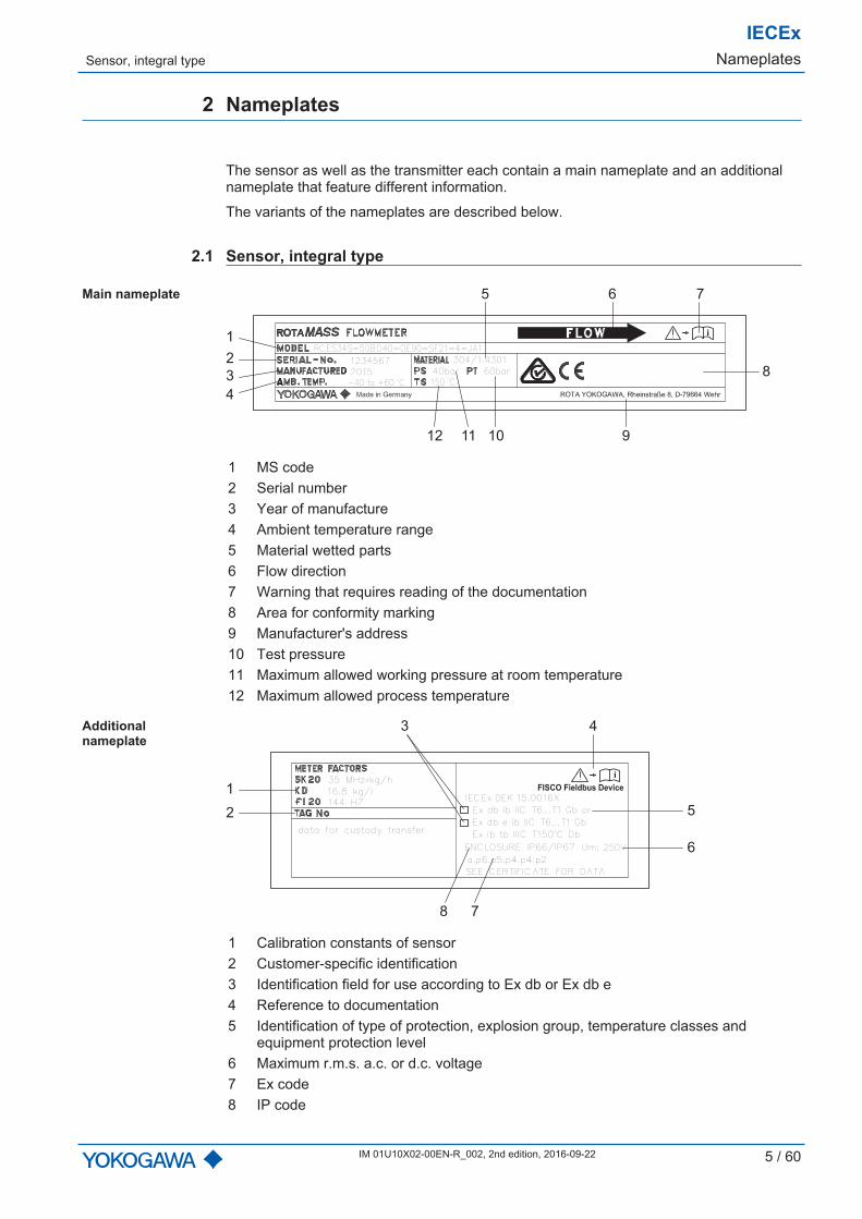
2.1 Sensor, integral type
Main nameplate
12 11 10 9
5 6 7
2
1
4
3 8
RCES34S-50BD40-OE90-SF21-4-JA1
12345672015-40 to +60
oC40bar 60bar150
oC
304/1.4301
i
1 MS code2 Serial number3 Year of manufacture4 Ambient temperature range5 Material wetted parts6 Flow direction7 Warning that requires reading of the documentation8 Area for conformity marking9 Manufacturer's address10 Test pressure11 Maximum allowed working pressure at room temperature12 Maximum allowed process temperature
Additionalnameplate
1
2 5
6
43
8 7
i
SEE CERTIFICATE FOR DATA
ENCLOSURE IP66/IP67 Um: 250V
Ex ib tb IIIC T150oC Db
Ex db e ib IIC T6...T1 Gb
Ex db ib IIC T6...T1 Gb or
IECEx DEK 15.0016X
a.p6.p5.p4.p4.p2
data for custody transfer
35 MHzxkg/h16.8 kg/l144 HZ
FISCO Fieldbus Device
1 Calibration constants of sensor2 Customer-specific identification3 Identification field for use according to Ex db or Ex db e4 Reference to documentation5 Identification of type of protection, explosion group, temperature classes and
equipment protection level6 Maximum r.m.s. a.c. or d.c. voltage7 Ex code8 IP code
IECExNameplates Transmitter, integral type
6 / 60 IM 01U10X02-00EN-R_002, 2nd edition, 2016-09-22
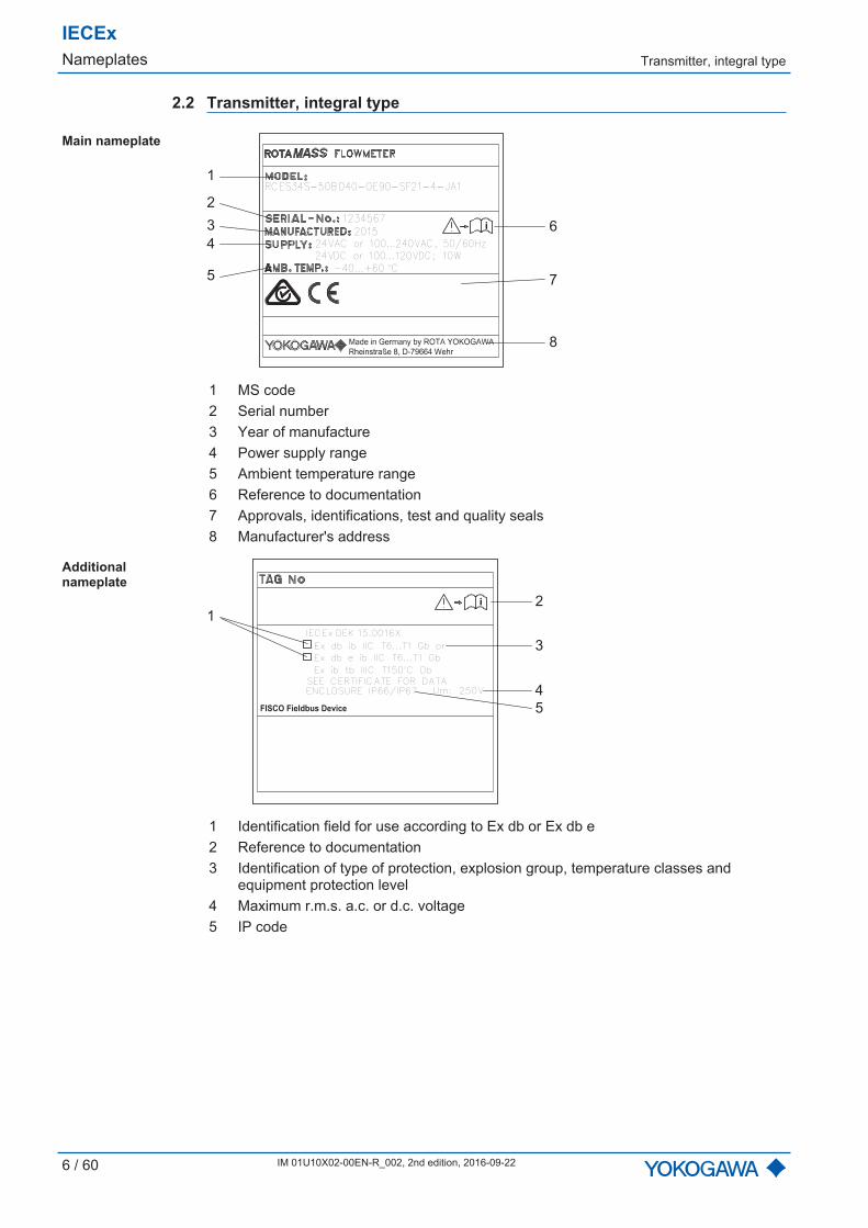
2.2 Transmitter, integral type
Main nameplate
i
1
2
3
4
5
6
7
8
RCES34S-50BD40-OE90-SF21-4-JA1
12345672015
24VAC or 100...240VAC, 50/60Hz24VDC or 100...120VDC; 10W
-40...+60 oC
1 MS code2 Serial number3 Year of manufacture4 Power supply range5 Ambient temperature range6 Reference to documentation7 Approvals, identifications, test and quality seals8 Manufacturer's address
Additionalnameplate
1
3
2
4
5
SEE CERTIFICATE FOR DATAENCLOSURE IP66/IP67 Um: 250V
Ex ib tb IIIC T150oC Db
Ex db e ib IIC T6...T1 Gb
Ex db ib IIC T6...T1 Gb or
i
IECEx DEK 15.0016X
FISCO Fieldbus Device
1 Identification field for use according to Ex db or Ex db e2 Reference to documentation3 Identification of type of protection, explosion group, temperature classes and
equipment protection level4 Maximum r.m.s. a.c. or d.c. voltage5 IP code

Sensor, remote type
IECExNameplates
IM 01U10X02-00EN-R_002, 2nd edition, 2016-09-22 7 / 60
2.3 Sensor, remote type
Main nameplate
12 11 10 9
5 6 7
2
1
4
3 8
RCES34S-50BD40-OE90-SF21-4-JA1
12345672015-40 to +60
oC40bar 60bar150
oC
304/1.4301
i
1 MS code2 Serial number3 Year of manufacture4 Ambient temperature range5 Material wetted parts6 Flow direction7 Warning that requires reading of the documentation8 Area for conformity marking9 Manufacturer's address10 Test pressure11 Maximum allowed working pressure at room temperature12 Maximum allowed process temperature
Additionalnameplate
1
24
5
6
3
i
SEE CERTIFICATE FOR DATA
IP66/67
Ex ib IIIC T150oC Db
Ex ib IIC T6...T1 Gb or
IECEx DEK 15.0016X
35 MHzxkg/h16.8 kg/l144 HZ
a.p6.p5.p4.p4.p2
FISCO Fieldbus Device
1 Calibration constants of sensor2 Customer-specific identification3 Reference to documentation4 Identification of type of protection, explosion group, temperature classes and
equipment protection level5 Ex code6 IP code

IECExNameplates Transmitter, remote type
8 / 60 IM 01U10X02-00EN-R_002, 2nd edition, 2016-09-22
2.4 Transmitter, remote type
Main nameplate
i
1
2
3
4
5
6
7
8
RCES34S-50BD40-OE90-SF21-4-JA1
12345672015
24VAC or 100...240VAC, 50/60Hz24VDC or 100...120VDC; 10W
-40...+60 oC
1 MS code2 Serial number3 Year of manufacture4 Power supply range5 Ambient temperature range6 Reference to documentation7 Approvals, identifications, test and quality seals8 Manufacturer's address
Additionalnameplate
1
4
3
5
6
i
2 FISCO Fieldbus Device
1 Identification field for use according to Ex db or Ex db e2 FISCO marking (only present for devices with Fieldbus communication)3 Reference to documentation4 Identification of type of protection, explosion group, temperature classes and equip-
ment protection level5 Maximum r.m.s. a.c. or d.c. voltage6 IP code
MS code
IECExOrdering information
IM 01U10X02-00EN-R_002, 2nd edition, 2016-09-22 9 / 60
3 Ordering information
3.1 MS code
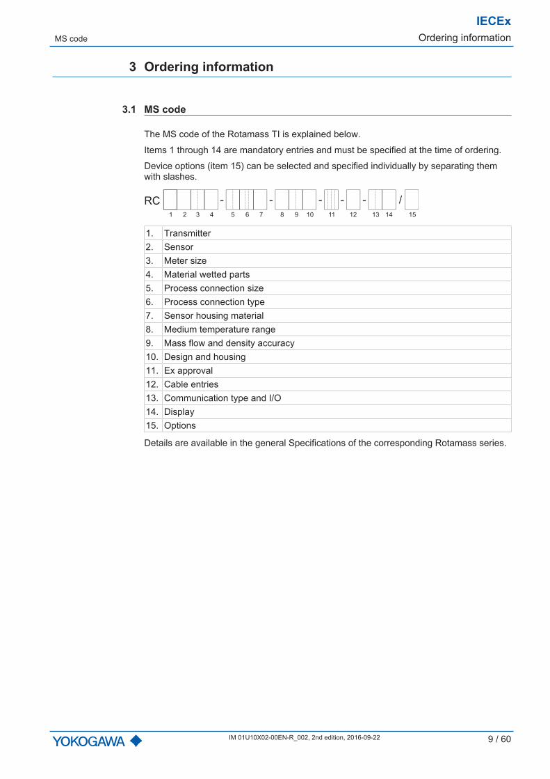
The MS code of the Rotamass TI is explained below.
Items 1 through 14 are mandatory entries and must be specified at the time of ordering.
Device options (item 15) can be selected and specified individually by separating themwith slashes.
- - - - /-RC
1 2 3 4 6 75 9 10 11 12 13 14 158
1. Transmitter2. Sensor3. Meter size4. Material wetted parts5. Process connection size6. Process connection type7. Sensor housing material8. Medium temperature range9. Mass flow and density accuracy10. Design and housing11. Ex approval12. Cable entries13. Communication type and I/O14. Display15. Options
Details are available in the general Specifications of the corresponding Rotamass series.
IECExInstallation General installation rules
10 / 60 IM 01U10X02-00EN-R_002, 2nd edition, 2016-09-22
4 Installation
4.1 General installation rules
DANGERExplosion hazard from electrostatic discharge or brush dischargeLife-threatening injuries or ignition of explosive atmospheres▶ Avoid actions that could lead to electrostatic discharges. For example, do not wipe the
coated surface of the transmitter using a piece of cloth.▶ Install the device in zone 1 or 21 so as to avoid the risk of electrostatic discharges and
brush discharges caused by rapid dust flow.
Modifying the coriolis mass flow meter as well as using unauthorized parts is prohibited andwill void the certification.
▪ Only trained personnel may install and operate the device in an industrial environment.
▪ The instructions have to be read and understood by all persons authorized with thetransport, storage, installation, electrical installation, commissioning, operation, mainte-nance and disposal of the Coriolis mass flow meter in hazardous areas.
▪ The respective applicable national safety regulations concerning the installation of theCoriolis mass flow meter in hazardous areas must be followed.
▪ Only media to which the wetted parts are sufficiently resistant may be used.
▪ The use of suitable cable glands must be ensured, see Threads for cable glands[} 11].
▪ Ambient and medium temperature must not exceed the respective maximum values forthe applicable Temperature specification by temperature classes [} 44].
▪ The integral type and the remote-type transmitter must not be insulated.
Threads for cable glands
IECExInstallation
IM 01U10X02-00EN-R_002, 2nd edition, 2016-09-22 11 / 60
4.2 Threads for cable glands
The terminal box in the transmitter for connecting the sensor is certified as Ex i. IP66/67-certified cable glands and blind plugs must be used for this connection. At a minimum,the allowable temperature range for cable glands and blind plugs must extend from -40...+80 °C. Blind plugs for redundant bushings and cable glands are factory-installed.
The housing of the transmitter is designed as type of protection Ex db. Optionally, the ter-minal box for the power supply and the inputs/outputs is also certified as Ex e. Properlycertified cable glands and blind plugs must be used for this purpose. At a minimum, theallowable temperature range for cable glands and blind plugs must extend from -40...+80 °C. The type of protection is to be indicated on the nameplate's identificationfields, see Nameplates [} 5].
If the device is to be operated without communication lines, the cable gland providedmust be replaced by a blind plug of the same classification.
2
3
M/N/W
4
5
1
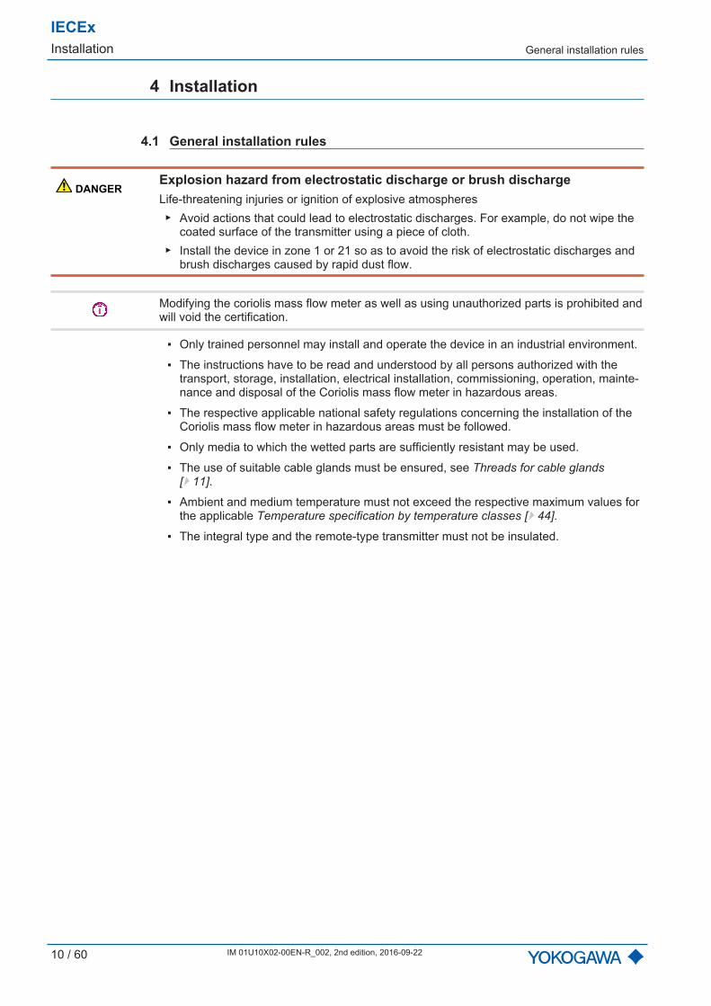
Fig. 1: Threads for the cable glands of the transmitter
1...5 Thread position, see the following tableM Marking of thread size: ISO M20 × 1.5N or W Marking of thread size: ANSI 1/2" NPT
The following figure shows the relevant position of the MS code:
- - - - /-RC
1 2 3 4 6 75 9 10 11 12 13 14 158

IECExInstallation Threads for cable glands
12 / 60 IM 01U10X02-00EN-R_002, 2nd edition, 2016-09-22
Thread MS codePosition 12
Threadposition
Delivery state NotesIntegral type Remote type
ISO M20 × 1.5 4
1Blind plugIP66/67, factory-installed
Metal cable glandIP66/67, factory-installed
–
2Blind plugIP66/67, factory-installed
Blind plugIP66/67, factory-installed
–
3 Cable gland Ex e tb IP66/67, factory-added
A properly certified IP66/67 ca-ble gland must be provided andprofessionally installed by theuser for type of protection Exdb.
4 Blind plug Ex e ta IP66/67, factory-in-stalled
A properly certified IP66/67blind plug must be provided andprofessionally installed by theuser for type of protection Exdb.
5 Cable gland Ex e tb IP66/67, factory-added
A properly certified IP66/67 ca-ble gland must be provided andprofessionally installed by theuser for type of protection Exdb.
ANSI 1/2" NPT 2
1Blind plugIP66/67, factory-installed
Metal cable glandIP66/67, factory-installed
–
2Blind plugIP66/67, factory-installed
Blind plugIP66/67, factory-installed
–
3 –
Depending on the type of pro-tection used – Ex e, Ex db, Extb – properly certified cableglands with IP66/67 must beprovided and professionally in-stalled by the user.
4 Blind plug Ex db e ta IP66/67,factory-installed –
5 –
Depending on the type of pro-tection used – Ex e, Ex db, Extb – properly certified cableglands with IP66/67 must beprovided and professionally in-stalled by the user.
The cable gland on the sensor is factory-installed. At a minimum, the allowable cablegland temperature must include the range from -50...+100 °C for option L␣␣␣ and therange -50...+80 °C for option Y␣␣␣.

Ex d-relevant transmitter threads
IECExInstallation
IM 01U10X02-00EN-R_002, 2nd edition, 2016-09-22 13 / 60
4.3 Ex d-relevant transmitter threads
Ex-certified models are equipped with an Ex d transmitter housing.
1
2
2
2
3
Fig. 2: Ex d-relevant transmitter threads
1 Thread for display cover2 Threads for cable glands3 Thread for back cover
Technical data of Ex d-relevantthreads
Thread Leadin mm
Tolerancefield
Threads inengagementin mm
Minimumscrew-indepthin mm
Display cover 26g/6H ≥ 8 ≥ 16
Back cover 2
Cable glandsISO M20 × 1.5 1.5 6H ≥ 10 ≥ 15
ANSI 1/2" NPT 1.814 acc. toANSI B 1.20.1 ≥ 6 ≥ 13.605
IECExElectrical installation General rules
14 / 60 IM 01U10X02-00EN-R_002, 2nd edition, 2016-09-22
5 Electrical installation
5.1 General rules
DANGERInsufficient connection to the potential equalization systemLife-threatening injuries from electric shock or ignition of explosive atmospheres▶ Connect remote-type sensor via the grounding terminal outside of the housing to the
potential equalization system, see Grounding connections and intrinsically safe circuits[} 15].
▶ Connect transmitter to the potential equalization system via the grounding terminal out-side of the housing, see Grounding connections and intrinsically safe circuits [} 15].
▶ Connect grounding cable of power supply cable to the grounding screw in the terminalbox, see Grounding connections and intrinsically safe circuits [} 15].
▪ The relevant national standards must be considered for the electrical installation.
▪ Rotamass must be integrated into the potential equalization system of the hazardousarea.
▪ The potential equalization must be ensured alongside the intrinsically safe circuit.
▪ The power supply must be established with a voltage ≤ 250 V at the terminals L/+ andN/-.
▪ The grounding screw in the terminal box must be mechanically firmly connected withthe threaded hole.
▪ If the type of protection Ex e is used, cable cross sections of 0.8 to 2.5 mm2 must beused for the cables of the power supply and the cables of the inputs/outputs. The insu-lation of the cores must be stripped off 5 to 6 mm.
▪ The cable connections for the inputs/outputs must be established according to the con-nection tables [} 16]. In the process, it must be ensured that the connection typematches the corresponding position of the MS code on the nameplate.
▪ The maximum input parameters of the intrinsically safe outputs must not be exceeded.

Grounding connections and intrinsically safe circuits
IECExElectrical installation
IM 01U10X02-00EN-R_002, 2nd edition, 2016-09-22 15 / 60
5.2 Grounding connections and intrinsically safe circuits
3
2
1
Fig. 3: Grounding connections on transmitter and sensor
1 Grounding screw in terminal box for grounding conductor2 Grounding terminal on transmitter for potential equalization3 Grounding terminal on sensor for potential equalization
D +
D -
S1 +
S1 -
S2 +
S2 -
TP
1
TP
2
TP
3
D +
D -
S1 +
S1 -
S2 +
S2 -
TP1
TP2
TP3
COM
3 2 1
1 2 3 4 5 6
Fig. 4: Connection terminal circuits (transmitter on the left side, sensor on the right side)
1 Driver circuit 4 Signal grounding2 Sensor circuits 5 Transmitter3 Temperature measurement circuits 6 Sensor
IECExElectrical installation Transmitter connection terminals
16 / 60 IM 01U10X02-00EN-R_002, 2nd edition, 2016-09-22
5.3 Transmitter connection terminals
5.3.1 Configuration of input/output terminals for HART communication andFoundation Fieldbus
3
1
8
7
6
5
4
2
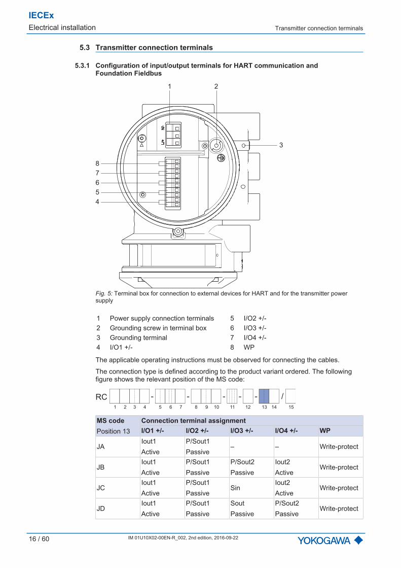
Fig. 5: Terminal box for connection to external devices for HART and for the transmitter powersupply
1 Power supply connection terminals 5 I/O2 +/-2 Grounding screw in terminal box 6 I/O3 +/-3 Grounding terminal 7 I/O4 +/-4 I/O1 +/- 8 WP
The applicable operating instructions must be observed for connecting the cables.
The connection type is defined according to the product variant ordered. The followingfigure shows the relevant position of the MS code:
- - - - /-RC
1 2 3 4 6 75 9 10 11 12 13 14 158
MS codePosition 13
Connection terminal assignmentI/O1 +/- I/O2 +/- I/O3 +/- I/O4 +/- WP
JAIout1Active
P/Sout1Passive
– – Write-protect
JBIout1Active
P/Sout1Passive
P/Sout2Passive
Iout2Active
Write-protect
JCIout1Active
P/Sout1Passive
SinIout2Active
Write-protect
JDIout1Active
P/Sout1Passive
SoutPassive
P/Sout2Passive
Write-protect
Transmitter connection terminals
IECExElectrical installation
IM 01U10X02-00EN-R_002, 2nd edition, 2016-09-22 17 / 60
MS codePosition 13
Connection terminal assignmentI/O1 +/- I/O2 +/- I/O3 +/- I/O4 +/- WP
JEIout1Active
P/Sout1Passive
SinP/Sout2Passive
Write-protect
JFIout1Active
P/Sout1Passive
Sin
P/Sout2ActiveInternal pull-up resistor
Write-protect
JGIout1Active
P/Sout1Passive
SinP/Sout2Active
Write-protect
JHIout1Active
P/Sout1Passive
Iout2Passive
IinActive
Write-protect
JJIout1Active
P/Sout1Passive
P/Sout2Passive
IinActive
Write-protect
JKIout1Active
P/Sout1Passive
SinIinActive
Write-protect
JLIout1Active
P/Sout1Passive
Iout2Passive
IinPassive
Write-protect
JMIout1Active
P/Sout1Passive
P/Sout2Passive
IinPassive
Write-protect
JNIout1Active
P/Sout1Passive
SinIinPassive
Write-protect
JPIout1Passive
P/Sout1Passive
Iout2Passive
– Write-protect
JQIout1Passive
P/Sout1Passive
Iout2Passive
P/Sout2Passive
Write-protect
JRIout1Passive
P/Sout1PassiveNAMUR
Iout2Passive
– Write-protect
JSIout1Passive
P/Sout1PassiveNAMUR
Iout2Passive
P/Sout2PassiveNAMUR
Write-protect
F␣ FoundationFieldbus – – – Write-protect
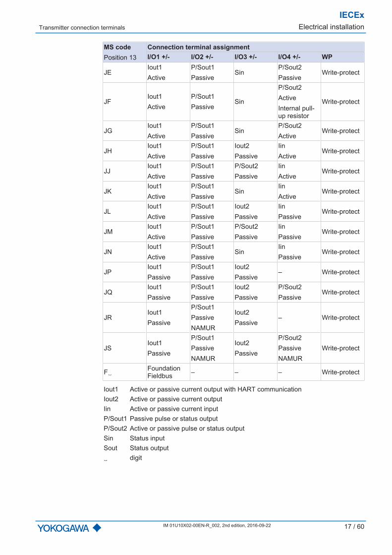
Iout1 Active or passive current output with HART communicationIout2 Active or passive current outputIin Active or passive current inputP/Sout1 Passive pulse or status outputP/Sout2 Active or passive pulse or status outputSin Status inputSout Status output␣ digit

IECExElectrical installation Transmitter connection terminals
18 / 60 IM 01U10X02-00EN-R_002, 2nd edition, 2016-09-22
5.3.2 Configuration of input/output terminals for Modbus communication
4
5
6
7
8
9
10
1 2
3
Fig. 6: Terminal box for connection to external devices for Modbus and for the transmitter powersupply
1 Power supply connection terminals 6 I/O3 +2 Grounding screw in terminal box 7 I/O3 -3 Grounding terminal 8 I/O4 +4 I/O1 +/- 9 I/O4 -5 I/O2 +/- 10 WP
The applicable operating instructions must be observed for connecting the cables.
The connection type is defined according to the product variant ordered. The followingfigure shows the relevant position of the MS code:
- - - - /-RC
1 2 3 4 6 75 9 10 11 12 13 14 158
MS codePosition13
Connection terminal assignmentI/O1 +/- I/O2 +/- I/O3 + I/O3 - I/O4 + I/O4 - WP
M0 –P/SoutPassive
– Modbus C Modbus B Modbus A Write-pro-tect
M2IinActive
P/SoutPassive
– Modbus C Modbus B Modbus A Write-pro-tect
M3P/SoutPassive
P/SoutPassive
– Modbus C Modbus B Modbus A Write-pro-tect
M4P/SoutActive
P/SoutPassive
– Modbus C Modbus B Modbus A Write-pro-tect
Installation diagrams
IECExElectrical installation
IM 01U10X02-00EN-R_002, 2nd edition, 2016-09-22 19 / 60
MS codePosition13
Connection terminal assignmentI/O1 +/- I/O2 +/- I/O3 + I/O3 - I/O4 + I/O4 - WP
M5
P/SoutActiveInternalpull-up re-sistor
P/SoutPassive
– Modbus C Modbus B Modbus A Write-pro-tect
M6IoutActive
P/SoutPassive
– Modbus C Modbus B Modbus A Write-pro-tect
M7IinPassive
P/SoutPassive
– Modbus C Modbus B Modbus A Write-pro-tect
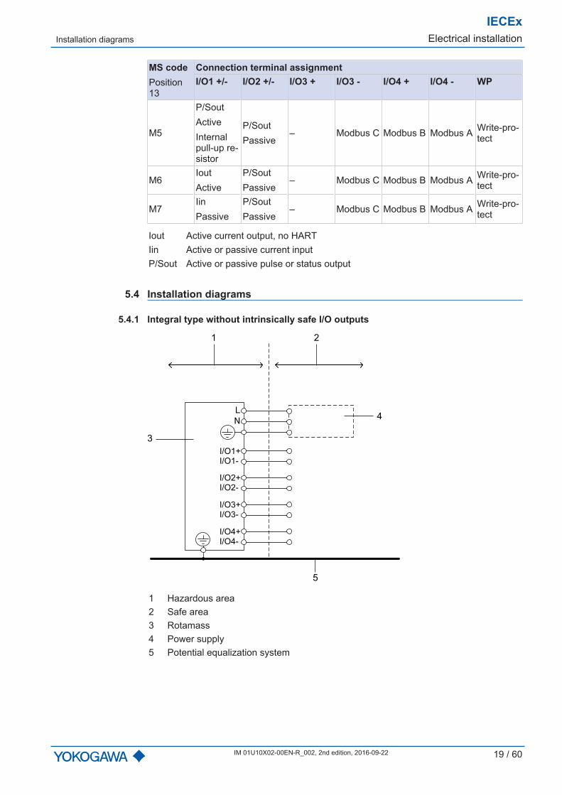
Iout Active current output, no HARTIin Active or passive current inputP/Sout Active or passive pulse or status output
5.4 Installation diagrams
5.4.1 Integral type without intrinsically safe I/O outputs
1 2
4
3
5
I/O1+
I/O1-
I/O2+
I/O2-
I/O3+
I/O3-
I/O4+
I/O4-
1 Hazardous area2 Safe area3 Rotamass4 Power supply5 Potential equalization system
IECExElectrical installation Installation diagrams
20 / 60 IM 01U10X02-00EN-R_002, 2nd edition, 2016-09-22
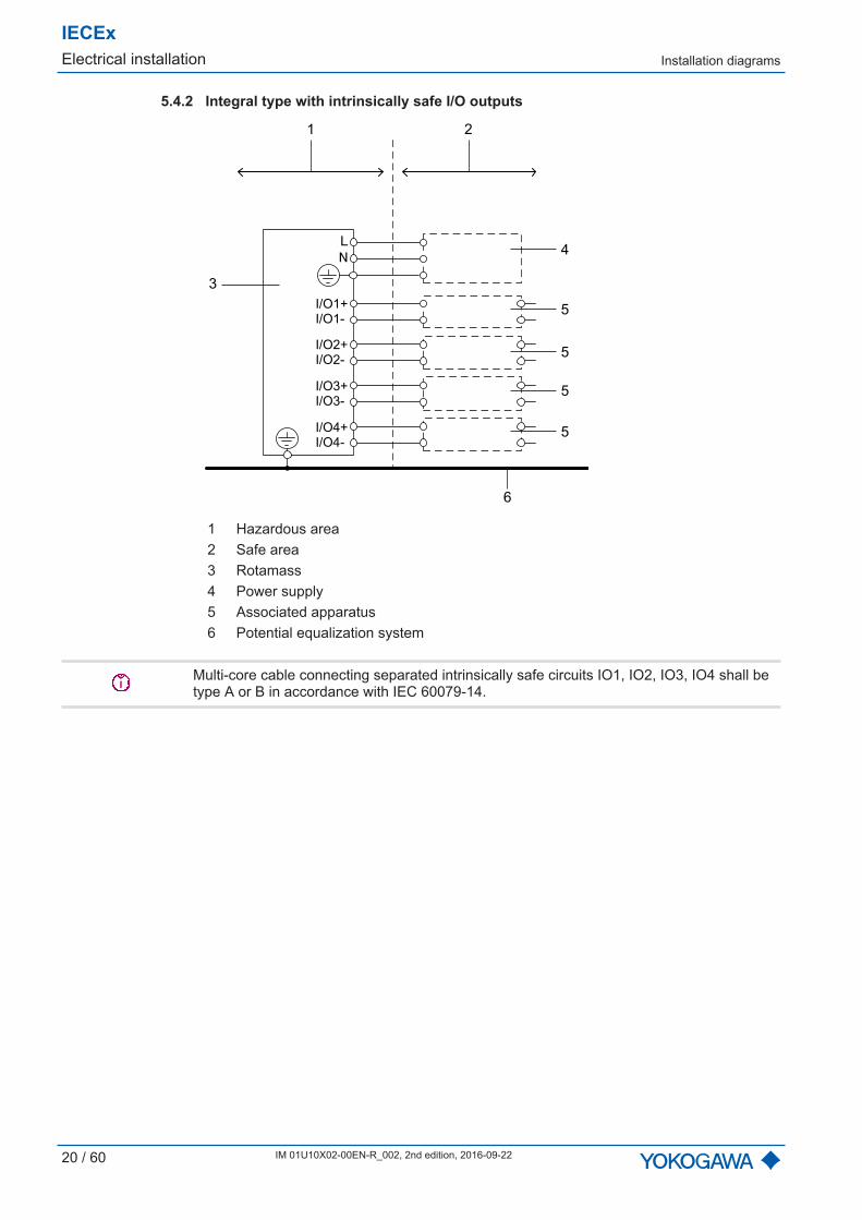
5.4.2 Integral type with intrinsically safe I/O outputs
1 2
4
5
5
5
5
3
6
I/O1+
I/O1-
I/O2+
I/O2-
I/O3+
I/O3-
I/O4+
I/O4-
1 Hazardous area2 Safe area3 Rotamass4 Power supply5 Associated apparatus6 Potential equalization system
Multi-core cable connecting separated intrinsically safe circuits IO1, IO2, IO3, IO4 shall betype A or B in accordance with IEC 60079-14.
Installation diagrams
IECExElectrical installation
IM 01U10X02-00EN-R_002, 2nd edition, 2016-09-22 21 / 60
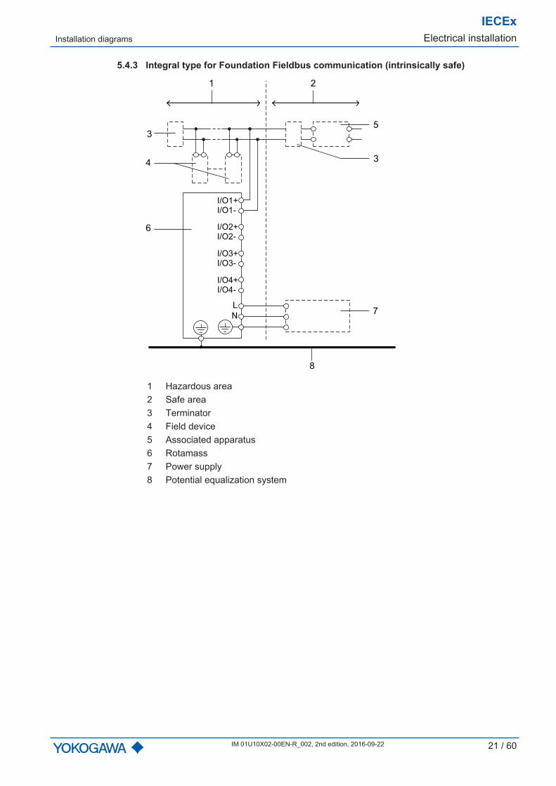
5.4.3 Integral type for Foundation Fieldbus communication (intrinsically safe)
1 2
7
6
8
I/O1+
I/O1-
I/O2+
I/O2-
I/O3+
I/O3-
I/O4+
I/O4-
3
3
5
4
1 Hazardous area2 Safe area3 Terminator4 Field device5 Associated apparatus6 Rotamass7 Power supply8 Potential equalization system
IECExElectrical installation Installation diagrams
22 / 60 IM 01U10X02-00EN-R_002, 2nd edition, 2016-09-22
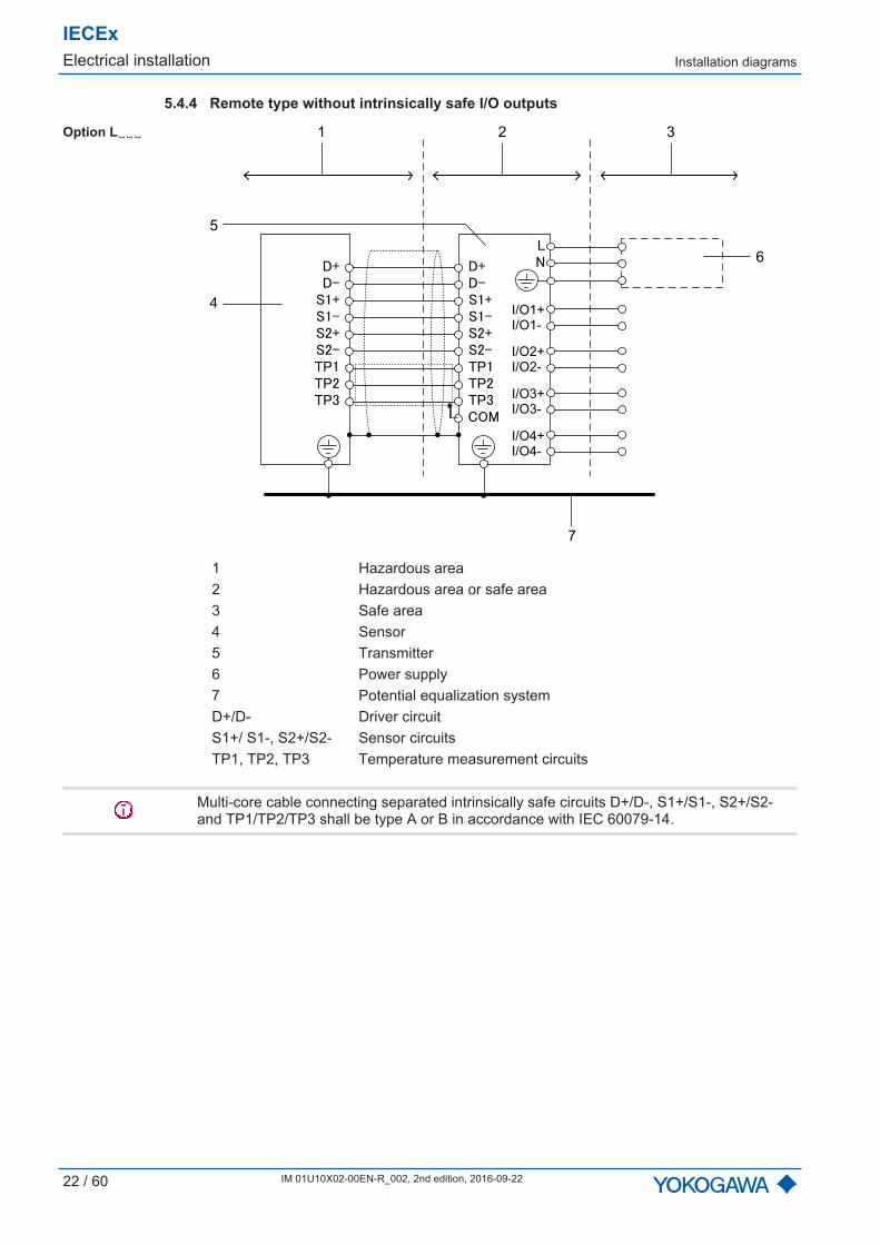
5.4.4 Remote type without intrinsically safe I/O outputs
Option L␣␣␣ 1 2 3
4
5
6
7
I/O1+
I/O1-
I/O2+
I/O2-
I/O3+
I/O3-
I/O4+
I/O4-
1 Hazardous area2 Hazardous area or safe area3 Safe area4 Sensor5 Transmitter6 Power supply7 Potential equalization systemD+/D- Driver circuitS1+/ S1-, S2+/S2- Sensor circuitsTP1, TP2, TP3 Temperature measurement circuits
Multi-core cable connecting separated intrinsically safe circuits D+/D-, S1+/S1-, S2+/S2-and TP1/TP2/TP3 shall be type A or B in accordance with IEC 60079-14.
Installation diagrams
IECExElectrical installation
IM 01U10X02-00EN-R_002, 2nd edition, 2016-09-22 23 / 60
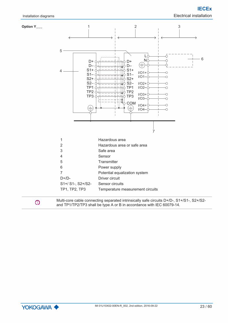
Option Y␣␣␣ 1 2 3
4
5
6
7
I/O1+
I/O1–
I/O2+
I/O2–
I/O3+
I/O3–
I/O4+
I/O4–
D+
D–
S1+
S1–
S2+
S2–
TP1
TP2
TP3
D+
D–
S1+
S1–
S2+
S2–
TP1
TP2
TP3
COM
L
N
1 Hazardous area2 Hazardous area or safe area3 Safe area4 Sensor5 Transmitter6 Power supply7 Potential equalization systemD+/D- Driver circuitS1+/ S1-, S2+/S2- Sensor circuitsTP1, TP2, TP3 Temperature measurement circuits
Multi-core cable connecting separated intrinsically safe circuits D+/D-, S1+/S1-, S2+/S2-and TP1/TP2/TP3 shall be type A or B in accordance with IEC 60079-14.
IECExElectrical installation Installation diagrams
24 / 60 IM 01U10X02-00EN-R_002, 2nd edition, 2016-09-22
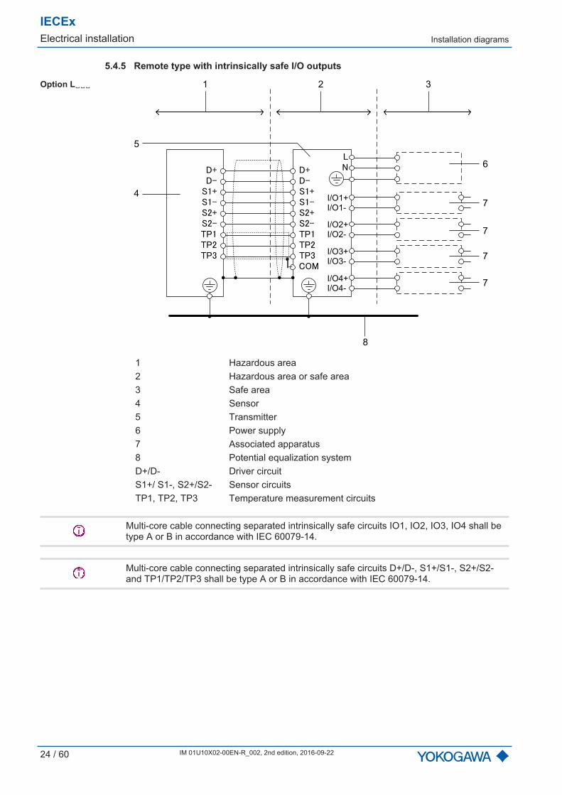
5.4.5 Remote type with intrinsically safe I/O outputs
Option L␣␣␣ 1 2 3
4
5
6
7
8
7
7
7
I/O1+
I/O1-
I/O2+
I/O2-
I/O3+
I/O3-
I/O4+
I/O4-
1 Hazardous area2 Hazardous area or safe area3 Safe area4 Sensor5 Transmitter6 Power supply7 Associated apparatus8 Potential equalization systemD+/D- Driver circuitS1+/ S1-, S2+/S2- Sensor circuitsTP1, TP2, TP3 Temperature measurement circuits
Multi-core cable connecting separated intrinsically safe circuits IO1, IO2, IO3, IO4 shall betype A or B in accordance with IEC 60079-14.
Multi-core cable connecting separated intrinsically safe circuits D+/D-, S1+/S1-, S2+/S2-and TP1/TP2/TP3 shall be type A or B in accordance with IEC 60079-14.
Installation diagrams
IECExElectrical installation
IM 01U10X02-00EN-R_002, 2nd edition, 2016-09-22 25 / 60
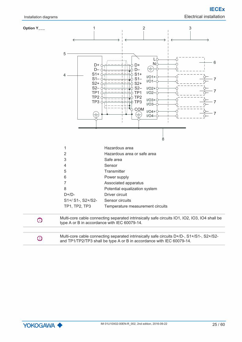
Option Y␣␣␣
7
7
7
7
1 2 3
4
5
6
8
I/O1+
I/O1–
I/O2+
I/O2–
I/O3+
I/O3–
I/O4+
I/O4–
D+
D–
S1+
S1–
S2+
S2–
TP1
TP2
TP3
D+
D–
S1+
S1–
S2+
S2–
TP1
TP2
TP3
COM
L
N
1 Hazardous area2 Hazardous area or safe area3 Safe area4 Sensor5 Transmitter6 Power supply7 Associated apparatus8 Potential equalization systemD+/D- Driver circuitS1+/ S1-, S2+/S2- Sensor circuitsTP1, TP2, TP3 Temperature measurement circuits
Multi-core cable connecting separated intrinsically safe circuits IO1, IO2, IO3, IO4 shall betype A or B in accordance with IEC 60079-14.
Multi-core cable connecting separated intrinsically safe circuits D+/D-, S1+/S1-, S2+/S2-and TP1/TP2/TP3 shall be type A or B in accordance with IEC 60079-14.

IECExElectrical installation Installation diagrams
26 / 60 IM 01U10X02-00EN-R_002, 2nd edition, 2016-09-22
5.4.6 Remote type for Foundation Fieldbus communication (intrinsically safe)
Option L␣␣␣ 1 2
6
7
8
9
3
3
5
4
I/O1+
I/O1–
I/O2+
I/O2–
I/O3+
I/O3–
I/O4+
I/O4–
D+
D–
S1+
S1–
S2+
S2–
TP1
TP2
TP3
D+
D–
S1+
S1–
S2+
S2–
TP1
TP2
TP3
COM
1 Hazardous area2 Safe area3 Terminator4 Field device5 Associated apparatus6 Sensor7 Transmitter8 Power supply9 Potential equalization systemD+/D- Driver circuitS1+/ S1-, S2+/S2- Sensor circuitsTP1, TP2, TP3 Temperature measurement circuits
Multi-core cable connecting separated intrinsically safe circuits D+/D-, S1+/S1-, S2+/S2-and TP1/TP2/TP3 shall be type A or B in accordance with IEC 60079-14.

Installation diagrams
IECExElectrical installation
IM 01U10X02-00EN-R_002, 2nd edition, 2016-09-22 27 / 60
Option Y␣␣␣ 1 2
6
7
8
9
I/O1+
I/O1–
I/O2+
I/O2–
I/O3+
I/O3–
I/O4+
I/O4–
D+
D–
S1+
S1–
S2+
S2–
TP1
TP2
TP3
D+
D–
S1+
S1–
S2+
S2–
TP1
TP2
TP3
COM
L
N
3
3
5
4
1 Hazardous area2 Safe area3 Terminator4 Field device5 Associated apparatus6 Sensor7 Transmitter8 Power supply9 Potential equalization systemD+/D- Driver circuitS1+/ S1-, S2+/S2- Sensor circuitsTP1, TP2, TP3 Temperature measurement circuits
Multi-core cable connecting separated intrinsically safe circuits D+/D-, S1+/S1-, S2+/S2-and TP1/TP2/TP3 shall be type A or B in accordance with IEC 60079-14.

IECExOperation, maintenance and repair General rules
28 / 60 IM 01U10X02-00EN-R_002, 2nd edition, 2016-09-22
6 Operation, maintenance and repair
6.1 General rules
DANGERLife-threatening injuries from electric shock▶ Switch off power supply.▶ Secure power supply against inadvertent switch-on.▶ Check that power supply is free of voltage.
DANGERLife-threatening injuries from ignition of explosive atmospheres▶ Wait 20 minutes before opening the housing until the capacitors have discharged and
components have cooled off.▶ Avoid electrostatically charging the device, e.g. by rubbing it with dry cloths.
Modifying the coriolis mass flow meter as well as using unauthorized parts is prohibited andwill void the certification.
▪ The locking screws of the covers may be loosened and tightened only with an Allenwrench.
▪ After closing and before commissioning, it must be checked whether the locking screwsare tightened and the covers are closed.
6.2 Replacing the sensor
If a defective Rotamass TI sensor must be replaced, contact the Yokogawa service.
The medium temperature range is indicated [} 5] by the Ex code on the sensor's addi-tional nameplate. Check whether there is a change in Ex code compared to the old sen-sor. If this is the case, the medium temperature range must be compared to the haz-ardous area requirements and assessed, see Ex code [} 40].
6.3 Replacing the transmitter
If a defective transmitter must be replaced, contact the Yokogawa service.
Observe the following items in order to obtain the replacement:
▪ Replace transmitter with option /EPT with a transmitter featuring the same option
▪ Transmitters as replacement for Rotamass 3 transmitters are identified by the value 3in the MS code (position 2)
The following figure shows the relevant positions of the MS code:
- - - - /-RC
1 2 3 4 6 75 9 10 11 12 13 14 158
IECExApprovals and standards
IM 01U10X02-00EN-R_002, 2nd edition, 2016-09-22 29 / 60
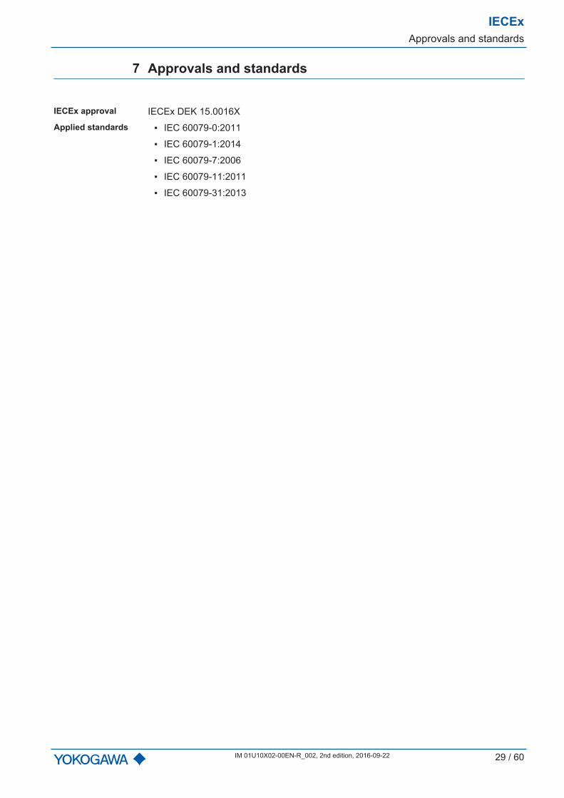
7 Approvals and standards
IECEx approval IECEx DEK 15.0016XApplied standards ▪ IEC 60079-0:2011
▪ IEC 60079-1:2014
▪ IEC 60079-7:2006
▪ IEC 60079-11:2011
▪ IEC 60079-31:2013

IECExTechnical data
30 / 60 IM 01U10X02-00EN-R_002, 2nd edition, 2016-09-22
8 Technical data
This chapter features the ex-relevant technical data.
Aside from the maximum surface temperature, the technical data of the integral type aswell as the remote type transmitters are identical, regardless of product family. For the re-mote-type sensor the technical data are different, depending on the product family.
▪ Integral type [} 31]
▪ Remote type– Nano [} 33]– Supreme, Intense and Giga sensor [} 34]– Prime and Hygienic sensor [} 35]– CNG sensor [} 33], [} 34]– LPG sensor [} 33], [} 34]– Transmitter [} 36]– Connecting cable [} 38]– Connection to Rotamass 3 sensor [} 39]
Integral type
IECExTechnical data
IM 01U10X02-00EN-R_002, 2nd edition, 2016-09-22 31 / 60
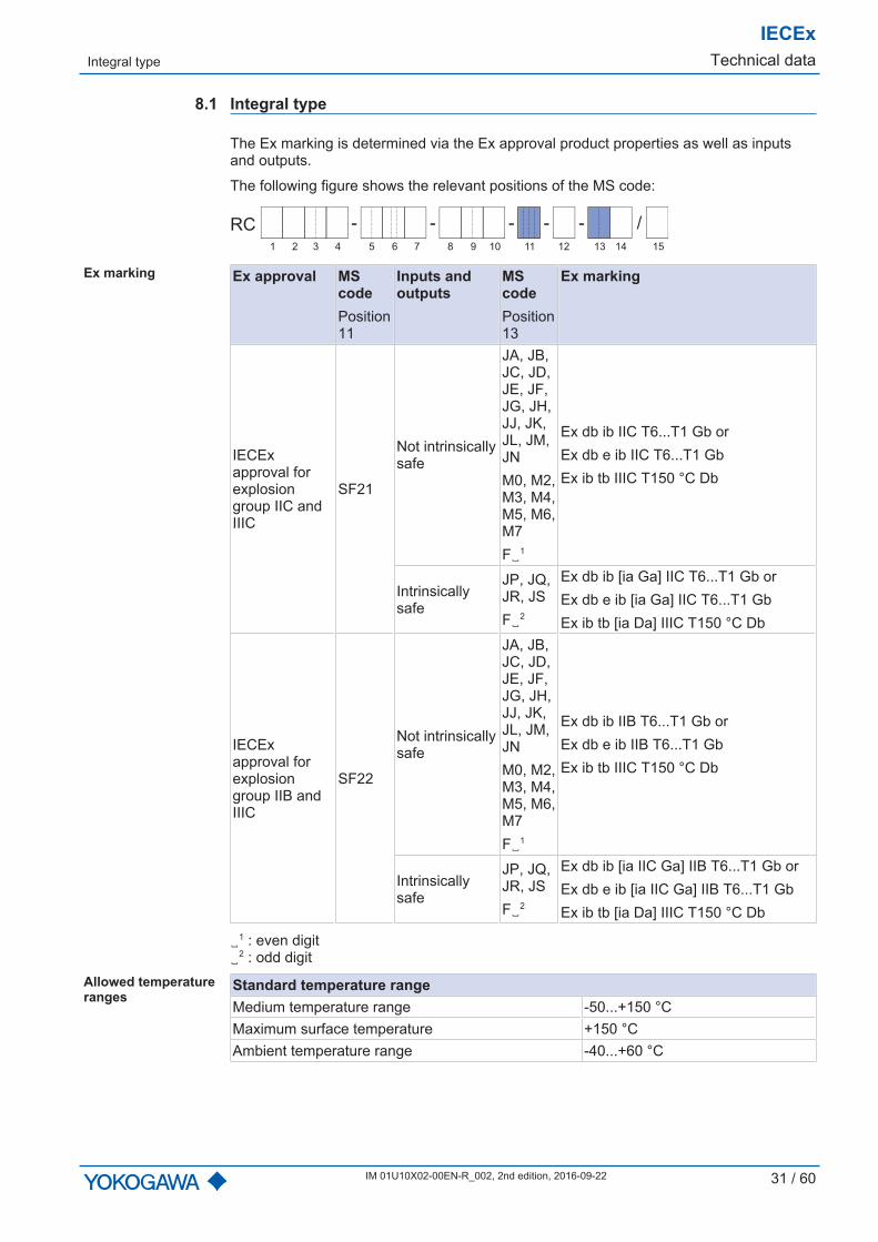
8.1 Integral type
The Ex marking is determined via the Ex approval product properties as well as inputsand outputs.
The following figure shows the relevant positions of the MS code:
- - - - /-RC
1 2 3 4 6 75 9 10 11 12 13 14 158
Ex marking Ex approval MScodePosition11
Inputs andoutputs
MScodePosition13
Ex marking
IECExapproval forexplosiongroup IIC andIIIC
SF21
Not intrinsicallysafe
JA, JB,JC, JD,JE, JF,JG, JH,JJ, JK,JL, JM,JNM0, M2,M3, M4,M5, M6,M7F␣1
Ex db ib IIC T6...T1 Gb orEx db e ib IIC T6...T1 GbEx ib tb IIIC T150 °C Db
Intrinsicallysafe
JP, JQ,JR, JSF␣2
Ex db ib [ia Ga] IIC T6...T1 Gb orEx db e ib [ia Ga] IIC T6...T1 GbEx ib tb [ia Da] IIIC T150 °C Db
IECExapproval forexplosiongroup IIB andIIIC
SF22
Not intrinsicallysafe
JA, JB,JC, JD,JE, JF,JG, JH,JJ, JK,JL, JM,JNM0, M2,M3, M4,M5, M6,M7F␣1
Ex db ib IIB T6...T1 Gb orEx db e ib IIB T6...T1 GbEx ib tb IIIC T150 °C Db
Intrinsicallysafe
JP, JQ,JR, JSF␣2
Ex db ib [ia IIC Ga] IIB T6...T1 Gb orEx db e ib [ia IIC Ga] IIB T6...T1 GbEx ib tb [ia Da] IIIC T150 °C Db
␣1 : even digit␣2 : odd digit
Allowed temperatureranges
Standard temperature rangeMedium temperature range -50...+150 °CMaximum surface temperature +150 °CAmbient temperature range -40...+60 °C

IECExTechnical data Integral type
32 / 60 IM 01U10X02-00EN-R_002, 2nd edition, 2016-09-22
Technical data Electrical data
Operating voltage VAC20.4...28.8 VAC or 80...250 VAC
Operating voltage VDC20.4...28.8 VDC or90...130 VDC
Maximum output 10 WOvervoltage category IIMaximum r.m.s. a.c. or d.c. voltage not intrinsically safe cir-cuits Um
250 V
Maximum input values for intrinsically safe current and pulse outputs(HART communication)Voltage Ui 30 VCurrent Ii 300 mAPower Pi 1.25 WInductance Li 12 µHElectrical capacitance Ci, for current output 4.84 nFElectrical capacitance Ci, for pulse output 14.6 nF
The dielectric strength of at least 500 V a.c. r.m.s. between the intrinsically safe circuitsand the enclosure is limited only by the overvoltage protection.
Maximum input values for intrinsically safe outputs(Foundation Fieldbus communication)Voltage Ui 30 VCurrent Ii 380 mAPower Pi 5.32 WInductance Li 10 µHElectrical capacitance Ci 5 nFFISCO field device
The dielectric strength of at least 500 V a.c. r.m.s. between the intrinsically safe circuitsand the enclosure is limited only by the overvoltage protection.
Ambient conditionsIP code of housing IP66/IP67Relative humidity range 0...95 %Allowed pollution degree according to EN 61010-1 4 (in operation)
Remote type
IECExTechnical data
IM 01U10X02-00EN-R_002, 2nd edition, 2016-09-22 33 / 60
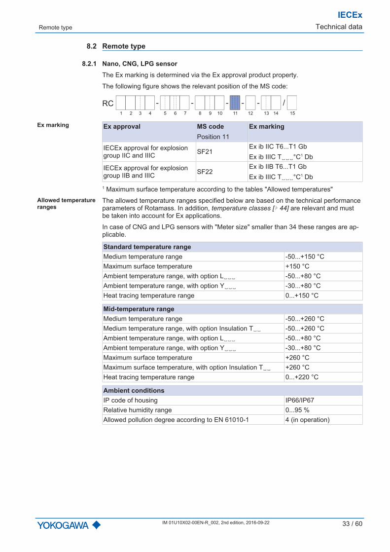
8.2 Remote type
8.2.1 Nano, CNG, LPG sensorThe Ex marking is determined via the Ex approval product property.
The following figure shows the relevant position of the MS code:
- - - - /-RC
1 2 3 4 6 75 9 10 11 12 13 14 158
Ex marking Ex approval MS codePosition 11
Ex marking
IECEx approval for explosiongroup IIC and IIIC SF21
Ex ib IIC T6...T1 GbEx ib IIIC T␣␣␣°C1 Db
IECEx approval for explosiongroup IIB and IIIC SF22
Ex ib IIB T6...T1 GbEx ib IIIC T␣␣␣°C1 Db
1 Maximum surface temperature according to the tables "Allowed temperatures"Allowed temperatureranges
The allowed temperature ranges specified below are based on the technical performanceparameters of Rotamass. In addition, temperature classes [} 44] are relevant and mustbe taken into account for Ex applications.
In case of CNG and LPG sensors with "Meter size" smaller than 34 these ranges are ap-plicable.
Standard temperature rangeMedium temperature range -50...+150 °CMaximum surface temperature +150 °CAmbient temperature range, with option L␣␣␣ -50...+80 °CAmbient temperature range, with option Y␣␣␣ -30...+80 °CHeat tracing temperature range 0...+150 °C
Mid-temperature rangeMedium temperature range -50...+260 °CMedium temperature range, with option Insulation T␣␣ -50...+260 °CAmbient temperature range, with option L␣␣␣ -50...+80 °CAmbient temperature range, with option Y␣␣␣ -30...+80 °CMaximum surface temperature +260 °CMaximum surface temperature, with option Insulation T␣␣ +260 °CHeat tracing temperature range 0...+220 °C
Ambient conditionsIP code of housing IP66/IP67Relative humidity range 0...95 %Allowed pollution degree according to EN 61010-1 4 (in operation)
IECExTechnical data Remote type
34 / 60 IM 01U10X02-00EN-R_002, 2nd edition, 2016-09-22
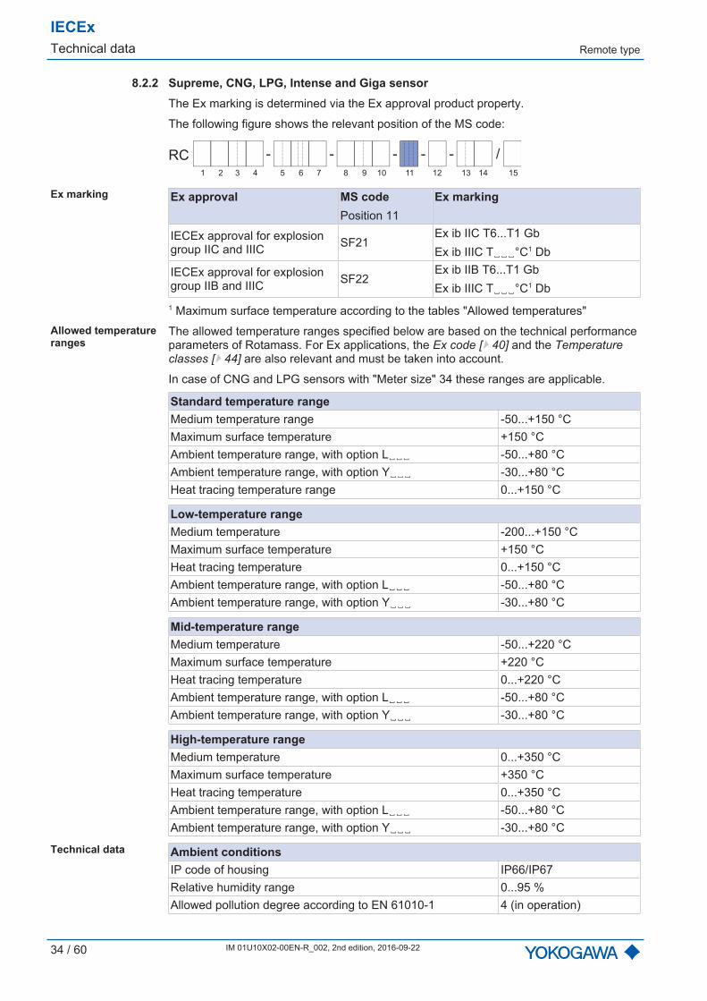
8.2.2 Supreme, CNG, LPG, Intense and Giga sensorThe Ex marking is determined via the Ex approval product property.
The following figure shows the relevant position of the MS code:
- - - - /-RC
1 2 3 4 6 75 9 10 11 12 13 14 158
Ex marking Ex approval MS codePosition 11
Ex marking
IECEx approval for explosiongroup IIC and IIIC SF21
Ex ib IIC T6...T1 GbEx ib IIIC T␣␣␣°C1 Db
IECEx approval for explosiongroup IIB and IIIC SF22
Ex ib IIB T6...T1 GbEx ib IIIC T␣␣␣°C1 Db
1 Maximum surface temperature according to the tables "Allowed temperatures"Allowed temperatureranges
The allowed temperature ranges specified below are based on the technical performanceparameters of Rotamass. For Ex applications, the Ex code [} 40] and the Temperatureclasses [} 44] are also relevant and must be taken into account.
In case of CNG and LPG sensors with "Meter size" 34 these ranges are applicable.
Standard temperature rangeMedium temperature range -50...+150 °CMaximum surface temperature +150 °CAmbient temperature range, with option L␣␣␣ -50...+80 °CAmbient temperature range, with option Y␣␣␣ -30...+80 °CHeat tracing temperature range 0...+150 °C
Low-temperature rangeMedium temperature -200...+150 °CMaximum surface temperature +150 °CHeat tracing temperature 0...+150 °CAmbient temperature range, with option L␣␣␣ -50...+80 °CAmbient temperature range, with option Y␣␣␣ -30...+80 °C
Mid-temperature rangeMedium temperature -50...+220 °CMaximum surface temperature +220 °CHeat tracing temperature 0...+220 °CAmbient temperature range, with option L␣␣␣ -50...+80 °CAmbient temperature range, with option Y␣␣␣ -30...+80 °C
High-temperature rangeMedium temperature 0...+350 °CMaximum surface temperature +350 °CHeat tracing temperature 0...+350 °CAmbient temperature range, with option L␣␣␣ -50...+80 °CAmbient temperature range, with option Y␣␣␣ -30...+80 °C
Technical data Ambient conditionsIP code of housing IP66/IP67Relative humidity range 0...95 %Allowed pollution degree according to EN 61010-1 4 (in operation)

Remote type
IECExTechnical data
IM 01U10X02-00EN-R_002, 2nd edition, 2016-09-22 35 / 60
8.2.3 Prime and Hygienic sensorThe Ex marking is determined via the Ex approval product property.
The following figure shows the relevant position of the MS code:
- - - - /-RC
1 2 3 4 6 75 9 10 11 12 13 14 158
Ex marking Ex approval MS codePosition 11
Ex marking
IECEx approval for explosiongroup IIC and IIIC SF21
Ex ib IIC T6...T1 GbEx ib IIIC T␣␣␣°C1 Db
IECEx approval for explosiongroup IIB and IIIC SF22
Ex ib IIB T6...T1 GbEx ib IIIC T␣␣␣°C1 Db
1 Maximum surface temperature according to the tables "Allowed temperatures"Allowed temperatureranges
The allowed temperature ranges specified below are based on the technical performanceparameters of Rotamass. For Ex applications, the Ex code [} 40] and the Temperatureclasses [} 44] are also relevant and must be taken into account.
Standard temperature rangeMedium temperature range -50...+200 °CMaximum surface temperature +200 °CAmbient temperature range, with option L␣␣␣ -50...+80 °CAmbient temperature range, with option Y␣␣␣ -30...+80 °C
Technical data Ambient conditionsIP code of housing IP66/IP67Relative humidity range 0...95 %Allowed pollution degree according to EN 61010-1 4 (in operation)
IECExTechnical data Remote type
36 / 60 IM 01U10X02-00EN-R_002, 2nd edition, 2016-09-22
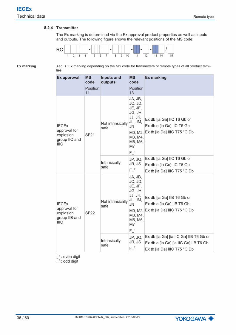
8.2.4 TransmitterThe Ex marking is determined via the Ex approval product properties as well as inputsand outputs. The following figure shows the relevant positions of the MS code:
- - - - /-RC
1 2 3 4 6 75 9 10 11 12 13 14 158
Ex marking Tab. 1: Ex marking depending on the MS code for transmitters of remote types of all product fami-lies
Ex approval MScodePosition11
Inputs andoutputs
MScodePosition13
Ex marking
IECExapproval forexplosiongroup IIC andIIIC
SF21
Not intrinsicallysafe
JA, JB,JC, JD,JE, JF,JG, JH,JJ, JK,JL, JM,JNM0, M2,M3, M4,M5, M6,M7F␣1
Ex db [ia Ga] IIC T6 Gb orEx db e [ia Ga] IIC T6 GbEx tb [ia Da] IIIC T75 °C Db
Intrinsicallysafe
JP, JQ,JR, JSF␣2
Ex db [ia Ga] IIC T6 Gb orEx db e [ia Ga] IIC T6 GbEx tb [ia Da] IIIC T75 °C Db
IECExapproval forexplosiongroup IIB andIIIC
SF22
Not intrinsicallysafe
JA, JB,JC, JD,JE, JF,JG, JH,JJ, JK,JL, JM,JNM0, M2,M3, M4,M5, M6,M7F␣1
Ex db [ia Ga] IIB T6 Gb orEx db e [ia Ga] IIB T6 GbEx tb [ia Da] IIIC T75 °C Db
Intrinsicallysafe
JP, JQ,JR, JSF␣2
Ex db [ia Ga] [ia IIC Ga] IIB T6 Gb orEx db e [ia Ga] [ia IIC Ga] IIB T6 GbEx tb [ia Da] IIIC T75 °C Db
␣1 : even digit␣2 : odd digit
Remote type
IECExTechnical data
IM 01U10X02-00EN-R_002, 2nd edition, 2016-09-22 37 / 60
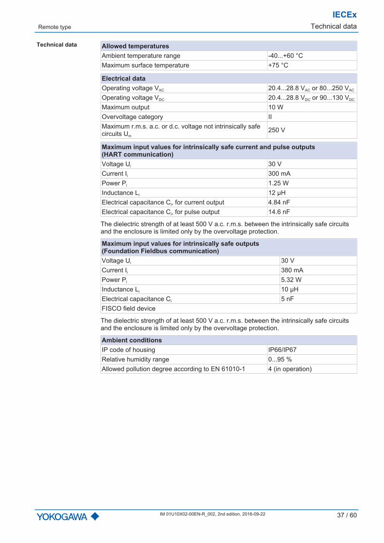
Technical data Allowed temperaturesAmbient temperature range -40...+60 °CMaximum surface temperature +75 °C
Electrical dataOperating voltage VAC 20.4...28.8 VAC or 80...250 VAC
Operating voltage VDC 20.4...28.8 VDC or 90...130 VDC
Maximum output 10 WOvervoltage category IIMaximum r.m.s. a.c. or d.c. voltage not intrinsically safecircuits Um
250 V
Maximum input values for intrinsically safe current and pulse outputs(HART communication)Voltage Ui 30 VCurrent Ii 300 mAPower Pi 1.25 WInductance Li 12 µHElectrical capacitance Ci, for current output 4.84 nFElectrical capacitance Ci, for pulse output 14.6 nF
The dielectric strength of at least 500 V a.c. r.m.s. between the intrinsically safe circuitsand the enclosure is limited only by the overvoltage protection.
Maximum input values for intrinsically safe outputs(Foundation Fieldbus communication)Voltage Ui 30 VCurrent Ii 380 mAPower Pi 5.32 WInductance Li 10 µHElectrical capacitance Ci 5 nFFISCO field device
The dielectric strength of at least 500 V a.c. r.m.s. between the intrinsically safe circuitsand the enclosure is limited only by the overvoltage protection.
Ambient conditionsIP code of housing IP66/IP67Relative humidity range 0...95 %Allowed pollution degree according to EN 61010-1 4 (in operation)

IECExTechnical data Remote type
38 / 60 IM 01U10X02-00EN-R_002, 2nd edition, 2016-09-22
8.2.5 Connecting cableTo connect the sensor with the transmitter, the following specifications must be adheredto for Ex applications:
Complete cableTemperature range, with option L␣␣␣: -50...+105 °CTemperature range, with option Y␣␣␣: -30...+80°C
Connection terminals/cablesection
Maximum inductance Maximum capacitance
D+/D-, S1+/ S1-, S2+/S2- < 0.03 mH < 90 nFTP1, TP2, TP3 < 158 mH < 11 µF
Calculation ofmaximum allowedcable length foroption L␣␣␣
The supplied connecting cable has the following line constants:
Line type Connectionterminals
Capacitancein nF/km
Inductancein mH/km
Core/core Core/shield
Coaxial D+/D-, S1+/ S1-,S2+/S2- 120 132 0.175
AWG20 TP1, TP2, TP3 145 290 0.7
The resulting maximum allowed cable length is:
Connectionterminals
Limitation Calculation Length limitation
D+/D-, S1+/ S1-,S2+/S2- Inductance 0.03 mH / (0.175 mH/km) = 171 m
D+/D-, S1+/ S1-,S2+/S2- Capacitance 90 nF / (132 nF/km) = 682 m
TP1, TP2, TP3 Inductance 158 mH / (0.7 mH/km) = 226 kmTP1, TP2, TP3 Capacitance 11 µF / (290 nF/km) = 38 km
Maximum allowed cable length = 171 m
See also installation diagrams, Remote type with intrinsically safe I/O outputs [} 24].Calculation ofmaximum allowedcable length foroption Y␣␣␣
The supplied marine cable has the following line constants:
Connection terminals Capacitancein nF/km
Inductancein mH/km
D+/D-, S1+/ S1-, S2+/S2-,TP1, TP2, TP3 81 0.315
Inductance and capacitance at terminals D+/D-, S1+/S1-, S2+/S2- are limiting.
Limitation Calculation Length limitationInductance 0.03 mH / (0.315 mH/km) = 95 m
Capacitance 90 nF / (81 nF/km) = 1.1 kmMaximum allowed cable length = 95 m
Remote type
IECExTechnical data
IM 01U10X02-00EN-R_002, 2nd edition, 2016-09-22 39 / 60
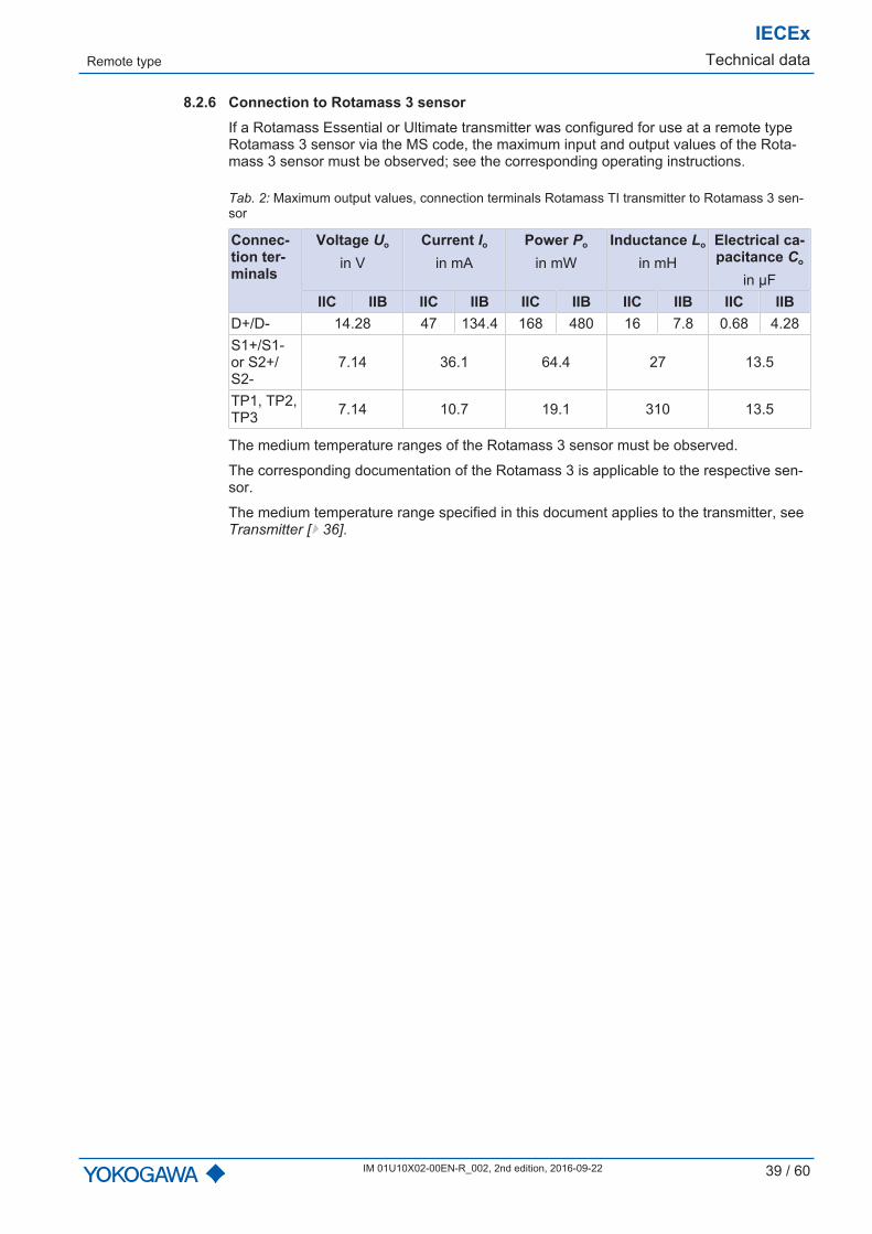
8.2.6 Connection to Rotamass 3 sensorIf a Rotamass Essential or Ultimate transmitter was configured for use at a remote typeRotamass 3 sensor via the MS code, the maximum input and output values of the Rota-mass 3 sensor must be observed; see the corresponding operating instructions.
Tab. 2: Maximum output values, connection terminals Rotamass TI transmitter to Rotamass 3 sen-sor
Connec-tion ter-minals
Voltage Uo
in VCurrent Io
in mAPower Po
in mWInductance Lo
in mHElectrical ca-pacitance Co
in µFIIC IIB IIC IIB IIC IIB IIC IIB IIC IIB
D+/D- 14.28 47 134.4 168 480 16 7.8 0.68 4.28S1+/S1-or S2+/S2-
7.14 36.1 64.4 27 13.5
TP1, TP2,TP3 7.14 10.7 19.1 310 13.5
The medium temperature ranges of the Rotamass 3 sensor must be observed.
The corresponding documentation of the Rotamass 3 is applicable to the respective sen-sor.
The medium temperature range specified in this document applies to the transmitter, seeTransmitter [} 36].

IECExTechnical data Ex code
40 / 60 IM 01U10X02-00EN-R_002, 2nd edition, 2016-09-22
8.3 Ex code
The Ex code, in combination with the MS code positions 2 and 10, allows determining themaximum medium and ambient temperatures for every temperature class according tothe Ex certificate. In each case, it is located on the additional nameplate [} 5] of the sen-sor, except for Rotamass Nano and all high-temperature versions. No Ex code is avail-able for these devices so that the medium temperature ranges must be taken directlyfrom the chapter Temperature specification by temperature classes [} 44].
i
SEE CERTIFICATE FOR DATA
IP66/67
Ex ib IIIC T150oC Db
Ex ib IIC T6...T1 Gb or
3.68.67.65.63.39
35 MHzxkg/h16.8 kg/l144 HZ IECEx DEK 15.0016X
Fig. 7: Additional nameplate with Ex code
Ex code design The Ex code is a 6-digit key with the following design:
. . . .3 68 67 65 63 . 39a p6 p5 p4 p3 p2. . . . .
a Ambient temperature column numberp6 Line number of maximum process temperature for temperature class T6p5 Line number of maximum process temperature for temperature class T5p4 Line number of maximum process temperature for temperature class T4p3 Line number of maximum process temperature for temperature class T3p2 Line number of maximum process temperature for temperature classes T2 and T1
8.3.1 Determining the maximum temperatures based on the Ex codeThe specific example below is intended to explain how to determine the maximummedium and ambient temperatures based on the Ex code and the MS code.
The complete tables of the medium temperature range are listed in the "Annex 1" of theEx certificate. Option (L␣␣␣ or Y␣␣␣) determines table a or b for remote variants. This ex-ample presents only excerpts thereof.
The following steps are performed to determine the maximum temperatures:
▶ Determining the maximum process temperature Tpro,max based on the Ex code, posi-tions p6...p2
▶ Determining the maximum ambient temperature Tamb pre based on the following crite-ria:
– MS code position 2 and 10– Ex code, position a– Determined maximum process temperatures Tpro,max

Ex code
IECExTechnical data
IM 01U10X02-00EN-R_002, 2nd edition, 2016-09-22 41 / 60
Problem definition: The allowed medium and ambient temperatures for a Rotamass Supreme 34 are to bedetermined based on the Ex code and the MS code on the nameplates.
The following MS code and Ex code are given:
RCUS34S-40CA40-OC5A-SF22-2-JR1/L005
12345672015-40 to +60
oC40bar 60bar150
oC
304/1.4301
i
i
SEE CERTIFICATE FOR DATA
IP66/67
Ex ib IIIC T150oC Db
Ex ib IIC T6...T1 Gb or
3.68.67.65.63.39
35 MHzxkg/h16.8 kg/l144 HZ IECEx DEK 15.0016X
U S 34 40S CA4 0 0 C5 A SF22 2 JR 1- - - - /-RC
1 2 3 4 6 75 9 10 11 12 13 148
L005
15
Fig. 8: MS code based on nameplate
. . . .3 68 67 65 63 . 39a p6 p5 p4 p3 p2. . . . .
Fig. 9: Ex code based on nameplate
Determining themaximum processtemperature Tpro,max
The values of the Ex code on the nameplate p6...p2 are the line indexes that determinethe maximum process temperatures Tpro,max according to Table 6 in the Ex certificate. Thetemperature class determines the applicable column.
Tab. 3: Excerpt from the medium temperature table of the Ex certificate: "Table 6: Process temper-atures according Ex-Code"
p2 to p6Ex-Codevalues
Tpro, maxin °C:for temperature classes
T6 T5 T4 T3 T2 T1... ... ... ... ... ... ...39 20 35 70 135 179 179... ... ... ... ... ... ...63 44 59 94 159 203 203... ... ... ... ... ... ...65 46 61 96 161 205 205... ... ... ... ... ... ...67 48 63 98 163 107 10768 49 64 99 164 208 208... ... ... ... ... ... ...
IECExTechnical data Ex code
42 / 60 IM 01U10X02-00EN-R_002, 2nd edition, 2016-09-22
For the temperature classes, this results in the following values for the maximum processtemperature:
▪ Temperature class T6 (column T6) and value of Ex code p6 (value = 68) define theintersection: Tpro, max = 49 °C
▪ Temperature class T5 (column T5) and value of Ex code p5 (value = 67) define theintersection: Tpro, max = 63 °C
▪ Temperature class T4 (column T4) and value of Ex code p4 (value = 65) define theintersection: Tpro, max = 96 °C
▪ Temperature class T3 (column T3) and value of Ex code p3 (value = 63) define theintersection: Tpro, max = 159 °C
▪ Temperature class T2 (column T2) and value of Ex code p2 (value = 39) define theintersection: Tpro, max = 179 °C
▪ Temperature class T1 (column T1) and value of Ex code p2 (value = 39) define theintersection: Tpro, max = 179 °C
These maximum process temperatures established must be used for further determina-tion of the ambient temperatures.
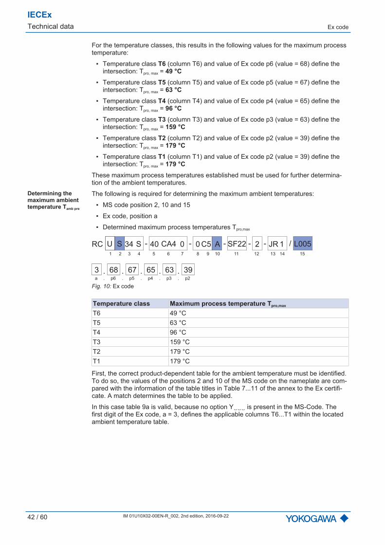
Determining themaximum ambienttemperature Tamb pre
The following is required for determining the maximum ambient temperatures:
▪ MS code position 2, 10 and 15
▪ Ex code, position a
▪ Determined maximum process temperatures Tpro,max
U S 34 40S CA4 0 0C5 A SF22 2 JR 1- - - - /-RC
1 2 3 4 6 75 9 10 11 12 13 148
L005
15
. . . .3 68 67 65 63 . 39a p6 p5 p4 p3 p2. . . . .
Fig. 10: Ex code
Temperature class Maximum process temperature Tpro,max
T6 49 °CT5 63 °CT4 96 °CT3 159 °CT2 179 °CT1 179 °C
First, the correct product-dependent table for the ambient temperature must be identified.To do so, the values of the positions 2 and 10 of the MS code on the nameplate are com-pared with the information of the table titles in Table 7...11 of the annex to the Ex certifi-cate. A match determines the table to be applied.
In this case table 9a is valid, because no option Y␣␣␣ is present in the MS-Code. Thefirst digit of the Ex code, a = 3, defines the applicable columns T6...T1 within the locatedambient temperature table.

Ex code
IECExTechnical data
IM 01U10X02-00EN-R_002, 2nd edition, 2016-09-22 43 / 60
The maximum process temperatures Tpro,max established define the applicable lines withinthe located ambient temperature table. If a value of the maximum process temperature isnot listed in the table, the next higher temperature value is used.
Determined maximum processtemperature
in °C
Next higher process temperaturein °C
49 5063 6596 100
159 160179 180179 180
Tab. 4: Excerpt from the ambient temperature table of the Ex certificate: "Table 9a: Ambient tem-perature table for designs: RC[2.]--[10.]--/ Applicable for Model Code part values: [2.] = S, G, C, L ,T; [10.] = A, C, E, J"
Tamb pre in °Ca: ... a = 2 a = 3 a = 4 ...Tproin°C
... T6 T5 T4 T3 T2T1
T6 T5 T4 T3 T2T1
T6 T5 T4 T3 T2T1
...
50 ... 69 80 80 80 80 62 77 80 80 80 58 73 80 80 80 ...... ... ... ... ... ... ... ... ... ... ... ... ... ... ... ... ... ...65 ... 69 80 80 80 80 61 77 80 80 80 55 73 80 80 80 ...... ... ... ... ... ... ... ... ... ... ... ... ... ... ... ... ... ...100 ... 80 80 80 80 80 80 80 80 80 ...... ... ... ... ... ... ... ... ... ... ... ... ... ... ... ... ... ...160 ... 74 74 74 74 74 74 ...... ... ... ... ... ... ... ... ... ... ... ... ... ... ... ... ... ...180 65 65 65 65 65 65 ...... ... ... ... ... ... ... ... ... ... ... ... ... ... ... ... ... ...
The value determined based on the ambient temperature table is a temporary value ofthe ambient temperature. Next, it must be compared with the determined maximumprocess temperature. The lower value determines the actual maximum ambient tempera-ture.
Result Determinedmaximum process
temperaturein °C
Temperature class Determinedtemporary value for
the ambienttemperature
in °C
Maximum ambienttemperature
in °C
49 T6 62 4963 T5 77 6396 T4 80 80
159 T3 74 74179 T2 65 65179 T1 65 65
IECExTechnical data Temperature specification by temperature classes
44 / 60 IM 01U10X02-00EN-R_002, 2nd edition, 2016-09-22
8.4 Temperature specification by temperature classes
Maximum ambient and process temperatures depending on explosion groups and tem-perature classes can be determined via the MS code or via the MS code together with theEx code.
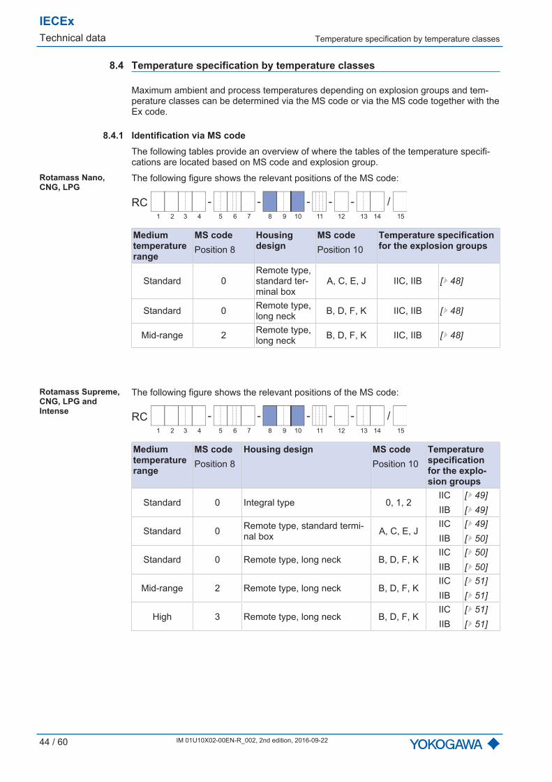
8.4.1 Identification via MS codeThe following tables provide an overview of where the tables of the temperature specifi-cations are located based on MS code and explosion group.
Rotamass Nano,CNG, LPG
The following figure shows the relevant positions of the MS code:
- - - - /-RC
1 2 3 4 6 75 9 10 11 12 13 14 158
Mediumtemperaturerange
MS codePosition 8
Housingdesign
MS codePosition 10
Temperature specificationfor the explosion groups
Standard 0Remote type,standard ter-minal box
A, C, E, J IIC, IIB [} 48]
Standard 0 Remote type,long neck B, D, F, K IIC, IIB [} 48]
Mid-range 2 Remote type,long neck B, D, F, K IIC, IIB [} 48]
Rotamass Supreme,CNG, LPG andIntense
The following figure shows the relevant positions of the MS code:
- - - - /-RC
1 2 3 4 6 75 9 10 11 12 13 14 158
Mediumtemperaturerange
MS codePosition 8
Housing design MS codePosition 10
Temperaturespecificationfor the explo-sion groups
Standard 0 Integral type 0, 1, 2IICIIB
[} 49][} 49]
Standard 0 Remote type, standard termi-nal box A, C, E, J
IICIIB
[} 49][} 50]
Standard 0 Remote type, long neck B, D, F, KIICIIB
[} 50][} 50]
Mid-range 2 Remote type, long neck B, D, F, KIICIIB
[} 51][} 51]
High 3 Remote type, long neck B, D, F, KIICIIB
[} 51][} 51]

Temperature specification by temperature classes
IECExTechnical data
IM 01U10X02-00EN-R_002, 2nd edition, 2016-09-22 45 / 60
Rotamass Giga The following figure shows the relevant positions of the MS code:
- - - - /-RC
1 2 3 4 6 75 9 10 11 12 13 14 158
Mediumtemperaturerange
MS codePosition 8
Housing design MS codePosition 10
Temperaturespecificationfor the explo-sion groups
Standard 0 Integral type 0, 1, 2IICIIB
[} 52][} 52]
Standard 0 Remote type, standardterminal box A, C, E, J
IICIIB
[} 52][} 53]
Standard 0 Remote type, long neck B, D, F, KIICIIB
[} 53][} 53]
Mid-range 2 Remote type, long neck B, D, F, KIICIIB
[} 54][} 54]
High 3 Remote type, long neck B, D, F, KIICIIB
[} 54][} 54]

IECExTechnical data Temperature specification by temperature classes
46 / 60 IM 01U10X02-00EN-R_002, 2nd edition, 2016-09-22
Rotamass Prime andHygienic
The following figure shows the relevant positions of the MS code:
- - - - /-RC
1 2 3 4 6 75 9 10 11 12 13 14 158
MS codePosition 3
Housing design MS codePosition 10
Deviceoption
MS codePosition15
Temperature speci-fication for the ex-plosion groups
25Integral type 0, 1, 2 – IIC, IIB [} 55]
4025
Integral type 0, 1, 2Expandedtempera-ture range
/EPT IIC, IIB [} 55]40
50 Integral type 0, 1, 2 – IIC, IIB [} 55]
50 Integral type 0, 1, 2Expandedtempera-ture range
/EPT IIC, IIB [} 56]
80 Integral type 0, 1, 2 –IICIIB
[} 56][} 56]
1H Integral type 0, 1, 2 – IIC, IIB [} 57]25 Remote type,
standard terminalbox
A, C, E, J – IIC, IIB [} 57]40
25 Remote type,standard terminalbox
A, C, E, JExpandedtempera-ture range
/EPT IIC, IIB [} 57]40
50Remote type,standard terminalbox
A, C, E, J – IIC, IIB [} 58]
50Remote type,standard terminalbox
A, C, E, JExpandedtempera-ture range
/EPT IIC, IIB [} 58]
80Remote type,standard terminalbox
A, C, E, J –IICIIB
[} 58][} 59]
1HRemote type,standard terminalbox
A, C, E, J – IIC, IIB [} 59]
Temperature specification by temperature classes
IECExTechnical data
IM 01U10X02-00EN-R_002, 2nd edition, 2016-09-22 47 / 60
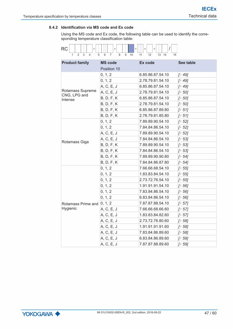
8.4.2 Identification via MS code and Ex codeUsing the MS code and Ex code, the following table can be used to identify the corre-sponding temperature classification table:
- - - - /-RC
1 2 3 4 6 75 9 10 11 12 13 14 158
Product family MS codePosition 10
Ex code See table
Rotamass SupremeCNG, LPG andIntense
0, 1, 2 6.85.86.87.54.10 [} 49]0, 1, 2 2.78.79.81.54.10 [} 49]A, C, E, J 6.85.86.87.54.10 [} 49]A, C, E, J 2.78.79.81.54.10 [} 50]B, D, F, K 6.85.86.87.54.10 [} 50]B, D, F, K 2.78.79.81.54.10 [} 50]B, D, F, K 6.85.86.87.89.80 [} 51]B, D, F, K 2.78.79.81.85.80 [} 51]
Rotamass Giga
0, 1, 2 7.89.89.90.54.10 [} 52]0, 1, 2 7.84.84.86.54.10 [} 52]A, C, E, J 7.89.89.90.54.10 [} 52]A, C, E, J 7.84.84.86.54.10 [} 53]B, D, F, K 7.89.89.90.54.10 [} 53]B, D, F, K 7.84.84.86.54.10 [} 53]B, D, F, K 7.89.89.90.90.80 [} 54]B, D, F, K 7.84.84.86.87.80 [} 54]
Rotamass Prime andHygienic
0, 1, 2 7.66.66.68.54.10 [} 55]0, 1, 2 1.83.83.84.54.10 [} 55]0, 1, 2 2.73.72.76.54.10 [} 55]0, 1, 2 1.91.91.91.54.10 [} 56]0, 1, 2 7.83.84.86.54.10 [} 56]0, 1, 2 6.83.84.86.54.10 [} 56]0, 1, 2 7.87.87.88.54.10 [} 57]A, C, E, J 7.66.66.68.66.60 [} 57]A, C, E, J 1.83.83.84.82.60 [} 57]A, C, E, J 2.73.72.76.80.60 [} 58]A, C, E, J 1.91.91.91.91.60 [} 58]A, C, E, J 7.83.84.86.89.60 [} 58]A, C, E, J 6.83.84.86.89.60 [} 59]A, C, E, J 7.87.87.88.89.60 [} 59]
IECExTechnical data Temperature specification by temperature classes
48 / 60 IM 01U10X02-00EN-R_002, 2nd edition, 2016-09-22
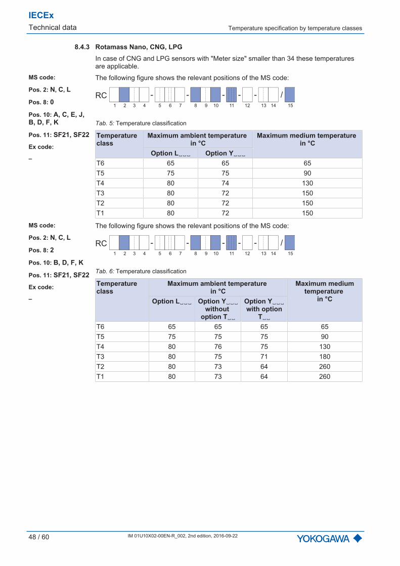
8.4.3 Rotamass Nano, CNG, LPGIn case of CNG and LPG sensors with "Meter size" smaller than 34 these temperaturesare applicable.
MS code:
Pos. 2: N, C, L
Pos. 8: 0
Pos. 10: A, C, E, J,B, D, F, K
Pos. 11: SF21, SF22
Ex code:
–
The following figure shows the relevant positions of the MS code:
- - - - /-RC
1 2 3 4 6 75 9 10 11 12 13 14 158
Tab. 5: Temperature classification
Temperatureclass
Maximum ambient temperature in °C
Maximum medium temperature in °C
Option L␣␣␣ Option Y␣␣␣T6 65 65 65T5 75 75 90T4 80 74 130T3 80 72 150T2 80 72 150T1 80 72 150
MS code:
Pos. 2: N, C, L
Pos. 8: 2
Pos. 10: B, D, F, K
Pos. 11: SF21, SF22
Ex code:
–
The following figure shows the relevant positions of the MS code:
- - - - /-RC
1 2 3 4 6 75 9 10 11 12 13 14 158
Tab. 6: Temperature classification
Temperatureclass
Maximum ambient temperature in °C
Maximum mediumtemperature
in °COption L␣␣␣ Option Y␣␣␣without
option T␣␣
Option Y␣␣␣with option
T␣␣T6 65 65 65 65T5 75 75 75 90T4 80 76 75 130T3 80 75 71 180T2 80 73 64 260T1 80 73 64 260
Temperature specification by temperature classes
IECExTechnical data
IM 01U10X02-00EN-R_002, 2nd edition, 2016-09-22 49 / 60
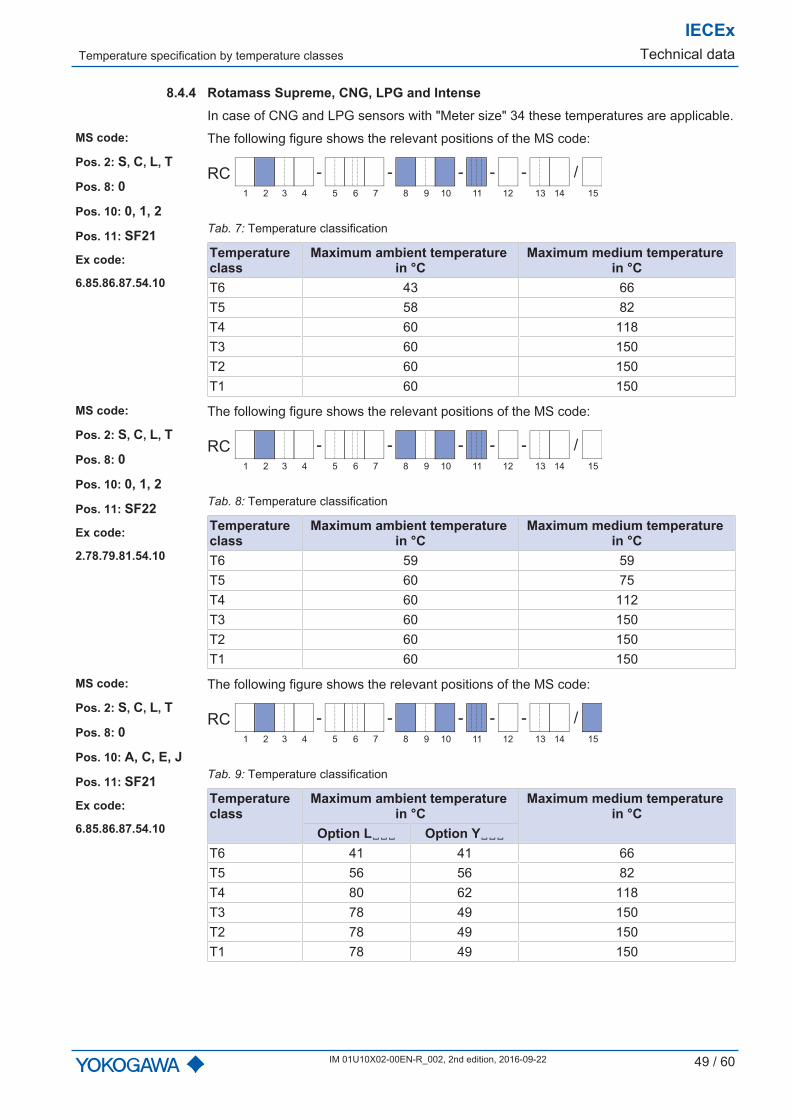
8.4.4 Rotamass Supreme, CNG, LPG and IntenseIn case of CNG and LPG sensors with "Meter size" 34 these temperatures are applicable.
MS code:
Pos. 2: S, C, L, T
Pos. 8: 0
Pos. 10: 0, 1, 2
Pos. 11: SF21
Ex code:
6.85.86.87.54.10
The following figure shows the relevant positions of the MS code:
- - - - /-RC
1 2 3 4 6 75 9 10 11 12 13 14 158
Tab. 7: Temperature classification
Temperatureclass
Maximum ambient temperature in °C
Maximum medium temperature in °C
T6 43 66T5 58 82T4 60 118T3 60 150T2 60 150T1 60 150
MS code:
Pos. 2: S, C, L, T
Pos. 8: 0
Pos. 10: 0, 1, 2
Pos. 11: SF22
Ex code:
2.78.79.81.54.10
The following figure shows the relevant positions of the MS code:
- - - - /-RC
1 2 3 4 6 75 9 10 11 12 13 14 158
Tab. 8: Temperature classification
Temperatureclass
Maximum ambient temperature in °C
Maximum medium temperature in °C
T6 59 59T5 60 75T4 60 112T3 60 150T2 60 150T1 60 150
MS code:
Pos. 2: S, C, L, T
Pos. 8: 0
Pos. 10: A, C, E, J
Pos. 11: SF21
Ex code:
6.85.86.87.54.10
The following figure shows the relevant positions of the MS code:
- - - - /-RC
1 2 3 4 6 75 9 10 11 12 13 14 158
Tab. 9: Temperature classification
Temperatureclass
Maximum ambient temperature in °C
Maximum medium temperature in °C
Option L␣␣␣ Option Y␣␣␣T6 41 41 66T5 56 56 82T4 80 62 118T3 78 49 150T2 78 49 150T1 78 49 150
IECExTechnical data Temperature specification by temperature classes
50 / 60 IM 01U10X02-00EN-R_002, 2nd edition, 2016-09-22
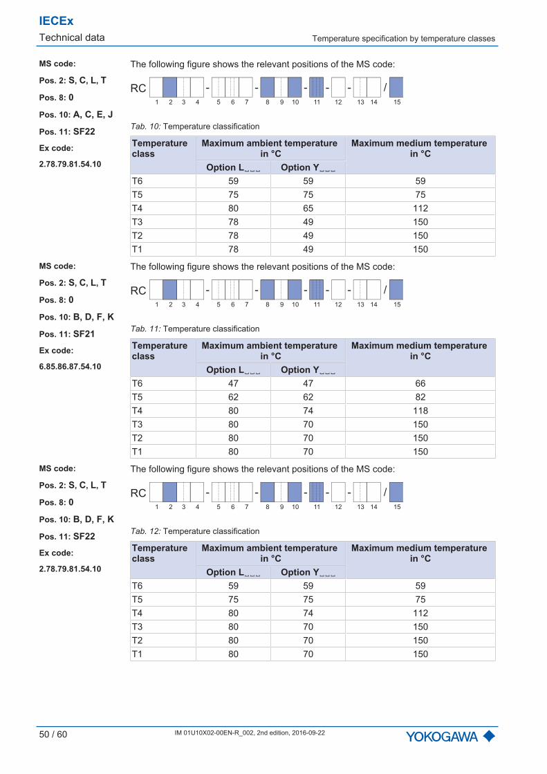
MS code:
Pos. 2: S, C, L, T
Pos. 8: 0
Pos. 10: A, C, E, J
Pos. 11: SF22
Ex code:
2.78.79.81.54.10
The following figure shows the relevant positions of the MS code:
- - - - /-RC
1 2 3 4 6 75 9 10 11 12 13 14 158
Tab. 10: Temperature classification
Temperatureclass
Maximum ambient temperature in °C
Maximum medium temperature in °C
Option L␣␣␣ Option Y␣␣␣T6 59 59 59T5 75 75 75T4 80 65 112T3 78 49 150T2 78 49 150T1 78 49 150
MS code:
Pos. 2: S, C, L, T
Pos. 8: 0
Pos. 10: B, D, F, K
Pos. 11: SF21
Ex code:
6.85.86.87.54.10
The following figure shows the relevant positions of the MS code:
- - - - /-RC
1 2 3 4 6 75 9 10 11 12 13 14 158
Tab. 11: Temperature classification
Temperatureclass
Maximum ambient temperature in °C
Maximum medium temperature in °C
Option L␣␣␣ Option Y␣␣␣T6 47 47 66T5 62 62 82T4 80 74 118T3 80 70 150T2 80 70 150T1 80 70 150
MS code:
Pos. 2: S, C, L, T
Pos. 8: 0
Pos. 10: B, D, F, K
Pos. 11: SF22
Ex code:
2.78.79.81.54.10
The following figure shows the relevant positions of the MS code:
- - - - /-RC
1 2 3 4 6 75 9 10 11 12 13 14 158
Tab. 12: Temperature classification
Temperatureclass
Maximum ambient temperature in °C
Maximum medium temperature in °C
Option L␣␣␣ Option Y␣␣␣T6 59 59 59T5 75 75 75T4 80 74 112T3 80 70 150T2 80 70 150T1 80 70 150

Temperature specification by temperature classes
IECExTechnical data
IM 01U10X02-00EN-R_002, 2nd edition, 2016-09-22 51 / 60
MS code:
Pos. 2: S, C, L, T
Pos. 8: 2
Pos. 10: B, D, F ,K
Pos. 11: SF21
Ex code:
6.85.86.87.89.80
The following figure shows the relevant positions of the MS code:
- - - - /-RC
1 2 3 4 6 75 9 10 11 12 13 14 158
Tab. 13: Temperature classification
Temperatureclass
Maximum ambient temperature in °C
Maximum medium temperature in °C
Option L␣␣␣ Option Y␣␣␣T6 47 47 66T5 62 62 82T4 80 74 118T3 80 64 185T2 80 59 220T1 80 59 220
MS code:
Pos. 2: S, C, L, T
Pos. 8: 2
Pos. 10: B, D, F, K
Pos. 11: SF22
Ex code:
2.78.79.81.85.80
The following figure shows the relevant positions of the MS code:
- - - - /-RC
1 2 3 4 6 75 9 10 11 12 13 14 158
Tab. 14: Temperature classification
Temperatureclass
Maximum ambient temperature in °C
Maximum medium temperature in °C
Option L␣␣␣ Option Y␣␣␣T6 59 59 59T5 75 75 75T4 80 74 112T3 80 64 181T2 80 59 220T1 80 59 220
MS code:
Pos. 2: S, T
Pos. 8: 3
Pos. 10: B, D, F, K
Pos. 11: SF21, SF22
Ex code:
–
The following figure shows the relevant positions of the MS code:
- - - - /-RC
1 2 3 4 6 75 9 10 11 12 13 14 158
Tab. 15: Temperature classification
Temperatureclass
Maximum ambient temperature in °C
Maximum medium temperature in °C
Option L␣␣␣ Option Y␣␣␣T6 62 62 65T5 77 77 80T4 80 74 115T3 80 65 180T2 73 50 275T1 60 40 350
IECExTechnical data Temperature specification by temperature classes
52 / 60 IM 01U10X02-00EN-R_002, 2nd edition, 2016-09-22
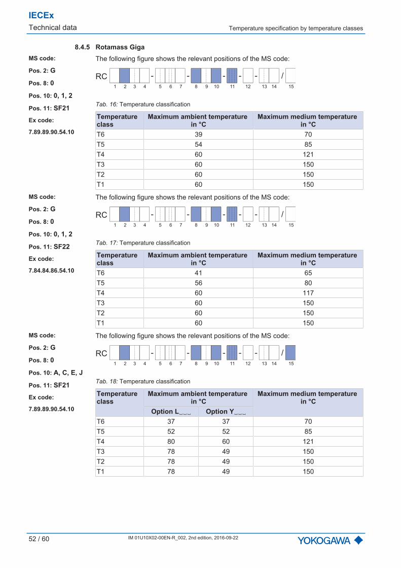
8.4.5 Rotamass GigaMS code:
Pos. 2: G
Pos. 8: 0
Pos. 10: 0, 1, 2
Pos. 11: SF21
Ex code:
7.89.89.90.54.10
The following figure shows the relevant positions of the MS code:
- - - - /-RC
1 2 3 4 6 75 9 10 11 12 13 14 158
Tab. 16: Temperature classification
Temperatureclass
Maximum ambient temperature in °C
Maximum medium temperature in °C
T6 39 70T5 54 85T4 60 121T3 60 150T2 60 150T1 60 150
MS code:
Pos. 2: G
Pos. 8: 0
Pos. 10: 0, 1, 2
Pos. 11: SF22
Ex code:
7.84.84.86.54.10
The following figure shows the relevant positions of the MS code:
- - - - /-RC
1 2 3 4 6 75 9 10 11 12 13 14 158
Tab. 17: Temperature classification
Temperatureclass
Maximum ambient temperature in °C
Maximum medium temperature in °C
T6 41 65T5 56 80T4 60 117T3 60 150T2 60 150T1 60 150
MS code:
Pos. 2: G
Pos. 8: 0
Pos. 10: A, C, E, J
Pos. 11: SF21
Ex code:
7.89.89.90.54.10
The following figure shows the relevant positions of the MS code:
- - - - /-RC
1 2 3 4 6 75 9 10 11 12 13 14 158
Tab. 18: Temperature classification
Temperatureclass
Maximum ambient temperature in °C
Maximum medium temperature in °C
Option L␣␣␣ Option Y␣␣␣T6 37 37 70T5 52 52 85T4 80 60 121T3 78 49 150T2 78 49 150T1 78 49 150

Temperature specification by temperature classes
IECExTechnical data
IM 01U10X02-00EN-R_002, 2nd edition, 2016-09-22 53 / 60
MS code:
Pos. 2: G
Pos. 8: 0
Pos. 10: A, C, E, J
Pos. 11: SF22
Ex code:
7.84.84.86.54.10
The following figure shows the relevant positions of the MS code:
- - - - /-RC
1 2 3 4 6 75 9 10 11 12 13 14 158
Tab. 19: Temperature classification
Temperatureclass
Maximum ambient temperature in °C
Maximum medium temperature in °C
Option L␣␣␣ Option Y␣␣␣T6 39 39 65T5 54 54 80T4 80 62 117T3 78 49 150T2 78 49 150T1 78 49 150
MS code:
Pos. 2: G
Pos. 8: 0
Pos. 10: B, D, F, K
Pos. 11: SF21
Ex code:
7.89.89.90.54.10
The following figure shows the relevant positions of the MS code:
- - - - /-RC
1 2 3 4 6 75 9 10 11 12 13 14 158
Tab. 20: Temperature classification
Temperatureclass
Maximum ambient temperature in °C
Maximum medium temperature in °C
Option L␣␣␣ Option Y␣␣␣T6 44 44 70T5 59 59 85T4 80 73 121T3 80 70 150T2 80 70 150T1 80 70 150
MS code:
Pos. 2: G
Pos. 8: 0
Pos. 10: B, D, F, K
Pos. 11: SF22
Ex code:
7.84.84.86.54.10
The following figure shows the relevant positions of the MS code:
- - - - /-RC
1 2 3 4 6 75 9 10 11 12 13 14 158
Tab. 21: Temperature classification
Temperatureclass
Maximum ambient temperature in °C
Maximum medium temperature in °C
Option L␣␣␣ Option Y␣␣␣T6 44 44 65T5 59 59 80T4 80 74 117T3 80 70 150T2 80 70 150T1 80 70 150

IECExTechnical data Temperature specification by temperature classes
54 / 60 IM 01U10X02-00EN-R_002, 2nd edition, 2016-09-22
MS code:
Pos. 2: G
Pos. 8: 2
Pos. 10: B, D, F, K
Pos. 11: SF21
Ex code:
7.89.89.90.90.80
The following figure shows the relevant positions of the MS code:
- - - - /-RC
1 2 3 4 6 75 9 10 11 12 13 14 158
Tab. 22: Temperature classification
Temperatureclass
Maximum ambient temperature in °C
Maximum medium temperature in °C
Option L␣␣␣ Option Y␣␣␣T6 44 44 70T5 59 59 85T4 80 73 121T3 80 64 186T2 80 59 220T1 80 59 220
MS code:
Pos. 2: G
Pos. 8: 2
Pos. 10: B, D, F, K
Pos. 11: SF22
Ex code:
7.84.84.86.87.80
The following figure shows the relevant positions of the MS code:
- - - - /-RC
1 2 3 4 6 75 9 10 11 12 13 14 158
Tab. 23: Temperature classification
Temperatureclass
Maximum ambient temperature in °C
Maximum medium temperature in °C
Option L␣␣␣ Option Y␣␣␣T6 44 44 65T5 59 59 80T4 80 74 117T3 80 64 183T2 80 59 220T1 80 59 220
MS code:
Pos. 2: G
Pos. 8: 3
Pos. 10: B, D, F, K
Pos. 11: SF21, SF22
Ex code:
–
The following figure shows the relevant positions of the MS code:
- - - - /-RC
1 2 3 4 6 75 9 10 11 12 13 14 158
Tab. 24: Temperature classification
Temperatureclass
Maximum ambient temperature in °C
Maximum medium temperature in °C
Option L␣␣␣ Option Y␣␣␣T6 62 62 65T5 77 77 80T4 80 74 115T3 80 65 180T2 73 50 275T1 60 40 350

Temperature specification by temperature classes
IECExTechnical data
IM 01U10X02-00EN-R_002, 2nd edition, 2016-09-22 55 / 60
8.4.6 Rotamass Prime and HygienicMS code:
Pos. 2: P, H
Pos. 3: 25, 40
Pos. 10: 0, 1, 2
Pos. 11: SF21, SF22
Pos. 15: –
Ex code:
7.66.66.68.54.10
The following figure shows the relevant positions of the MS code:
- - - - /-RC
1 2 3 4 6 75 9 10 11 12 13 14 158
Tab. 25: Temperature classification
Temperatureclass
Maximum ambient temperature in °C
Maximum medium temperature in °C
T6 43 47T5 58 62T4 60 99T3 60 150T2 60 150T1 60 150
MS code:
Pos. 2: P, H
Pos. 3: 25, 40
Pos. 10: 0, 1, 2
Pos. 11: SF21, SF22
Pos. 15: /EPT
Ex code:
1.83.83.84.54.10
The following figure shows the relevant positions of the MS code:
- - - - /-RC
1 2 3 4 6 75 9 10 11 12 13 14 158
Tab. 26: Temperature classification
Temperatureclass
Maximum ambient temperature in °C
Maximum medium temperature in °C
T6 60 64T5 60 79T4 60 115T3 60 150T2 60 150T1 60 150
MS code:
Pos. 2: P, H
Pos. 3: 50
Pos. 10: 0, 1, 2
Pos. 11: SF21, SF22
Pos. 15: –
Ex code:
2.73.72.76.54.10
The following figure shows the relevant positions of the MS code:
- - - - /-RC
1 2 3 4 6 75 9 10 11 12 13 14 158
Tab. 27: Temperature classification
Temperatureclass
Maximum ambient temperature in °C
Maximum medium temperature in °C
T6 54 54T5 60 68T4 60 107T3 60 150T2 60 150T1 60 150

IECExTechnical data Temperature specification by temperature classes
56 / 60 IM 01U10X02-00EN-R_002, 2nd edition, 2016-09-22
MS code:
Pos. 2: P, H
Pos. 3: 50
Pos. 10: 0, 1, 2
Pos. 11: SF21, SF22
Pos. 15: /EPT
Ex code:
1.91.91.91.54.10
The following figure shows the relevant positions of the MS code:
- - - - /-RC
1 2 3 4 6 75 9 10 11 12 13 14 158
Tab. 28: Temperature classification
Temperatureclass
Maximum ambient temperature in °C
Maximum medium temperature in °C
T6 60 72T5 60 87T4 60 122T3 60 150T2 60 150T1 60 150
MS code:
Pos. 2: P, H
Pos. 3: 80
Pos. 10: 0, 1, 2
Pos. 11: SF21
Pos. 15: –
Ex code:
7.83.84.86.54.10
The following figure shows the relevant positions of the MS code:
- - - - /-RC
1 2 3 4 6 75 9 10 11 12 13 14 158
Tab. 29: Temperature classification
Temperatureclass
Maximum ambient temperature in °C
Maximum medium temperature in °C
T6 40 64T5 55 80T4 60 117T3 60 150T2 60 150T1 60 150
MS code:
Pos. 2: P, H
Pos. 3: 80
Pos. 10: 0, 1, 2
Pos. 11: SF22
Pos. 15: –
Ex code:
6.83.84.86.54.10
The following figure shows the relevant positions of the MS code:
- - - - /-RC
1 2 3 4 6 75 9 10 11 12 13 14 158
Tab. 30: Temperature classification
Temperatureclass
Maximum ambient temperature in °C
Maximum medium temperature in °C
T6 44 64T5 59 80T4 60 117T3 60 150T2 60 150T1 60 150

Temperature specification by temperature classes
IECExTechnical data
IM 01U10X02-00EN-R_002, 2nd edition, 2016-09-22 57 / 60
MS code:
Pos. 2: P, H
Pos. 3: 1H
Pos. 10: 0, 1, 2
Pos. 11: SF21, SF22
Pos. 15: –
Ex code:
7.87.87.88.54.10
The following figure shows the relevant positions of the MS code:
- - - - /-RC
1 2 3 4 6 75 9 10 11 12 13 14 158
Tab. 31: Temperature classification
Temperatureclass
Maximum ambient temperaturein °C
Maximum medium temperaturein °C
T6 39 68T5 54 83T4 60 119T3 60 150T2 60 150T1 60 150
MS code:
Pos. 2: P, H
Pos. 3: 25, 40
Pos. 10: A, C, E, J
Pos. 11: SF21, SF22
Pos. 15: –
Ex code:
7.66.66.68.66.60
The following figure shows the relevant positions of the MS code:
- - - - /-RC
1 2 3 4 6 75 9 10 11 12 13 14 158
Tab. 32: Temperature classification
Temperatureclass
Maximum ambient temperature in °C
Maximum medium temperature in °C
Option L␣␣␣ Option Y␣␣␣T6 46 46 47T5 61 61 62T4 80 74 99T3 74 67 162T2 60 57 200T1 60 57 200
MS code:
Pos. 2: P, H
Pos. 3: 25, 40
Pos. 10: A, C, E, J
Pos. 11: SF21, SF22
Pos. 15: /EPT
Ex code:
1.83.83.84.82.60
The following figure shows the relevant positions of the MS code:
- - - - /-RC
1 2 3 4 6 75 9 10 11 12 13 14 158
Tab. 33: Temperature classification
Temperatureclass
Maximum ambient temperature in °C
Maximum medium temperature in °C
Option L␣␣␣ Option Y␣␣␣T6 64 64 64T5 79 79 79T4 80 73 115T3 68 63 178T2 60 57 200T1 60 57 200
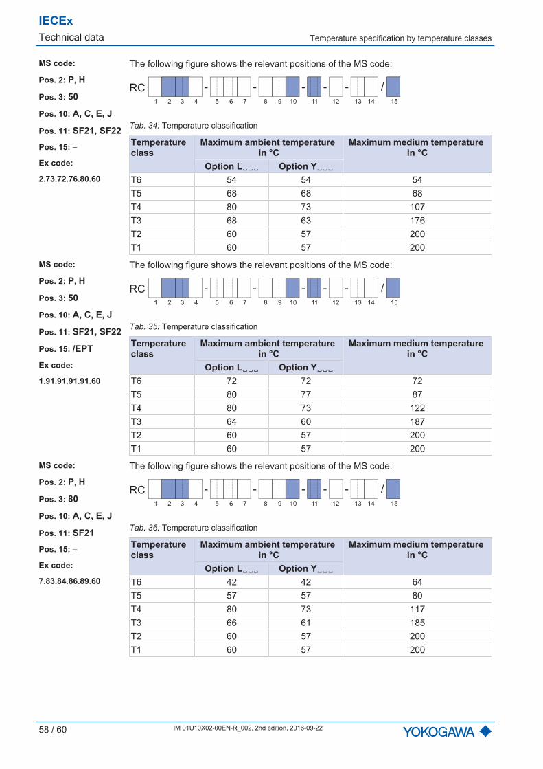
IECExTechnical data Temperature specification by temperature classes
58 / 60 IM 01U10X02-00EN-R_002, 2nd edition, 2016-09-22
MS code:
Pos. 2: P, H
Pos. 3: 50
Pos. 10: A, C, E, J
Pos. 11: SF21, SF22
Pos. 15: –
Ex code:
2.73.72.76.80.60
The following figure shows the relevant positions of the MS code:
- - - - /-RC
1 2 3 4 6 75 9 10 11 12 13 14 158
Tab. 34: Temperature classification
Temperatureclass
Maximum ambient temperature in °C
Maximum medium temperature in °C
Option L␣␣␣ Option Y␣␣␣T6 54 54 54T5 68 68 68T4 80 73 107T3 68 63 176T2 60 57 200T1 60 57 200
MS code:
Pos. 2: P, H
Pos. 3: 50
Pos. 10: A, C, E, J
Pos. 11: SF21, SF22
Pos. 15: /EPT
Ex code:
1.91.91.91.91.60
The following figure shows the relevant positions of the MS code:
- - - - /-RC
1 2 3 4 6 75 9 10 11 12 13 14 158
Tab. 35: Temperature classification
Temperatureclass
Maximum ambient temperature in °C
Maximum medium temperature in °C
Option L␣␣␣ Option Y␣␣␣T6 72 72 72T5 80 77 87T4 80 73 122T3 64 60 187T2 60 57 200T1 60 57 200
MS code:
Pos. 2: P, H
Pos. 3: 80
Pos. 10: A, C, E, J
Pos. 11: SF21
Pos. 15: –
Ex code:
7.83.84.86.89.60
The following figure shows the relevant positions of the MS code:
- - - - /-RC
1 2 3 4 6 75 9 10 11 12 13 14 158
Tab. 36: Temperature classification
Temperatureclass
Maximum ambient temperature in °C
Maximum medium temperature in °C
Option L␣␣␣ Option Y␣␣␣T6 42 42 64T5 57 57 80T4 80 73 117T3 66 61 185T2 60 57 200T1 60 57 200
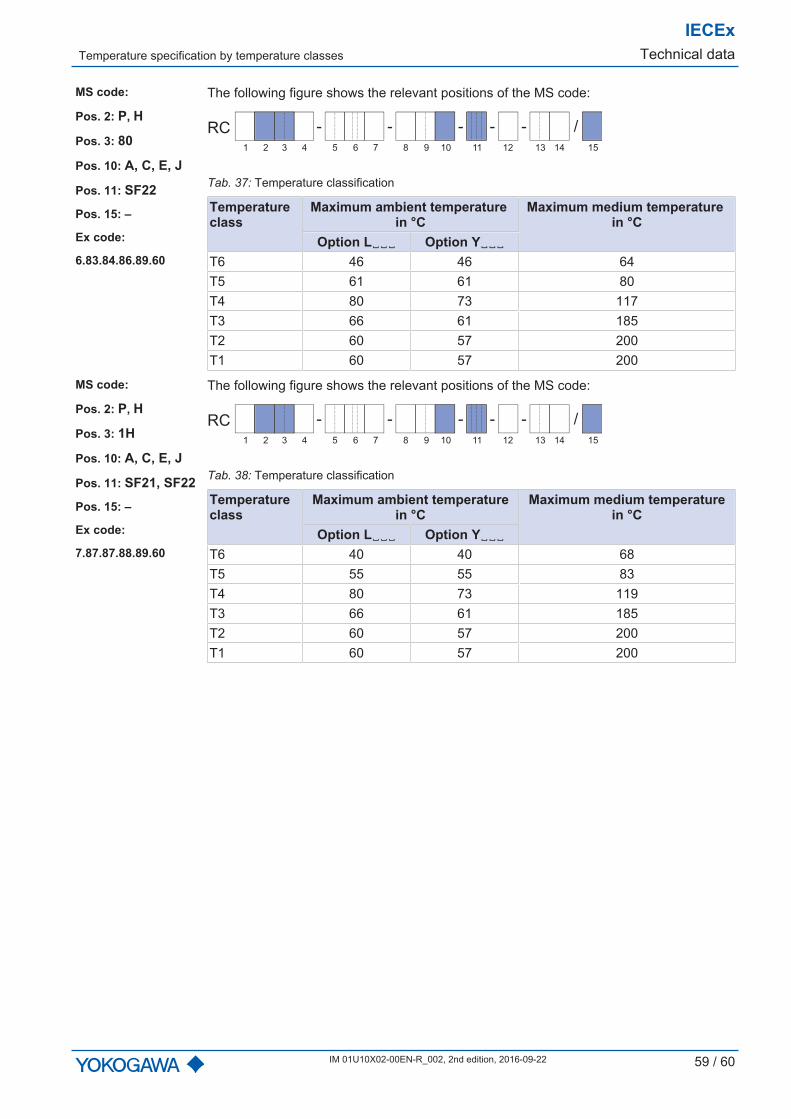
Temperature specification by temperature classes
IECExTechnical data
IM 01U10X02-00EN-R_002, 2nd edition, 2016-09-22 59 / 60
MS code:
Pos. 2: P, H
Pos. 3: 80
Pos. 10: A, C, E, J
Pos. 11: SF22
Pos. 15: –
Ex code:
6.83.84.86.89.60
The following figure shows the relevant positions of the MS code:
- - - - /-RC
1 2 3 4 6 75 9 10 11 12 13 14 158
Tab. 37: Temperature classification
Temperatureclass
Maximum ambient temperature in °C
Maximum medium temperature in °C
Option L␣␣␣ Option Y␣␣␣T6 46 46 64T5 61 61 80T4 80 73 117T3 66 61 185T2 60 57 200T1 60 57 200
MS code:
Pos. 2: P, H
Pos. 3: 1H
Pos. 10: A, C, E, J
Pos. 11: SF21, SF22
Pos. 15: –
Ex code:
7.87.87.88.89.60
The following figure shows the relevant positions of the MS code:
- - - - /-RC
1 2 3 4 6 75 9 10 11 12 13 14 158
Tab. 38: Temperature classification
Temperatureclass
Maximum ambient temperaturein °C
Maximum medium temperaturein °C
Option L␣␣␣ Option Y␣␣␣T6 40 40 68T5 55 55 83T4 80 73 119T3 66 61 185T2 60 57 200T1 60 57 200
Yokogawa has an extensive sales and
distribution network.
Please refer to the European website
(www.yokogawa.com/eu) to contact your
nearest representative.
Euroweg 2
3825 HD AMERSFOORT
The Netherlands
www.yokogawa.com/eu
YOKOGAWA ELECTRIC CORPORATION
World Headquarters
9-32, Nakacho 2-chome, Musashino-shi
Tokyo 180-8750
Japan
www.yokogawa.com
YOKOGAWA CORPORATION OF AMERICA
2 Dart Road
Newnan GA 30265
USA
www.yokogawa.com/us
Rota Yokogawa GmbH & Co. KG
P.O. Box 20, Rheinstraße 8
79664 Wehr
Germany
www.yokogawa.com/rota-de
YOKOGAWA ELECTRIC ASIA Pte. LTD.
5 Bedok South Road
Singapore 469270
Singapore
www.yokogawa.com/sg
YOKOGAWA CHINA CO. LTD.
3F Tower D Cartelo Crocodile Building
No.568 West Tianshan Road Changing District
Shanghai, China
www.yokogawa.com/cn
YOKOGAWA MIDDLE EAST B.S.C.(c)
P.O. Box 10070, Manama
Building 577, Road 2516, Busaiteen 225
Muharraq, Bahrain
www.yokogawa.com/bh
IM 01U10X02-00EN-R - 002, 2nd edition, 2016-09-22
All rights reserved. Copyright © 2016-09-22


