
Product Data SheetDecember 2012
00813-0100-4015, Rev GB
Rosemount 3095FT MultiVariable™ Flow Data Logger
Product Discontinued
The proven leader in Multivariable measurement
Industry leading performance with ±0.05% of DP reading accuracy
Ten year stability under actual process conditions
Unprecedented reliability backed by a limited 12-year warranty
Measures natural gas flow through an orifice plate per AGA, API, and GPA standards
Advanced data and event logging, API compliant
Rosemount 3095FT December 2012
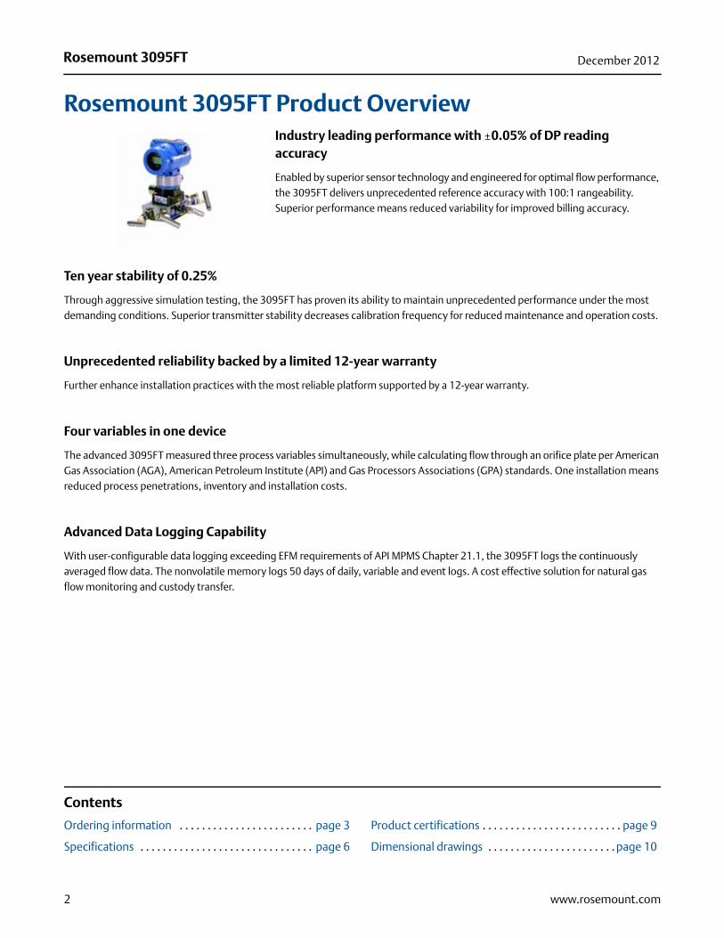
Rosemount 3095FT Product OverviewIndustry leading performance with ±0.05% of DP reading accuracy
Enabled by superior sensor technology and engineered for optimal flow performance, the 3095FT delivers unprecedented reference accuracy with 100:1 rangeability. Superior performance means reduced variability for improved billing accuracy.
Ten year stability of 0.25%
Through aggressive simulation testing, the 3095FT has proven its ability to maintain unprecedented performance under the most demanding conditions. Superior transmitter stability decreases calibration frequency for reduced maintenance and operation costs.
Unprecedented reliability backed by a limited 12-year warranty
Further enhance installation practices with the most reliable platform supported by a 12-year warranty.
Four variables in one device
The advanced 3095FT measured three process variables simultaneously, while calculating flow through an orifice plate per American Gas Association (AGA), American Petroleum Institute (API) and Gas Processors Associations (GPA) standards. One installation means reduced process penetrations, inventory and installation costs.
Advanced Data Logging Capability
With user-configurable data logging exceeding EFM requirements of API MPMS Chapter 21.1, the 3095FT logs the continuously averaged flow data. The nonvolatile memory logs 50 days of daily, variable and event logs. A cost effective solution for natural gas flow monitoring and custody transfer.
Contents
Ordering information . . . . . . . . . . . . . . . . . . . . . . . . page 3
Specifications . . . . . . . . . . . . . . . . . . . . . . . . . . . . . . . page 6
Product certifications . . . . . . . . . . . . . . . . . . . . . . . . . page 9
Dimensional drawings . . . . . . . . . . . . . . . . . . . . . . . page 10
2 www.rosemount.com
Rosemount 3095FTDecember 2012
Ordering information
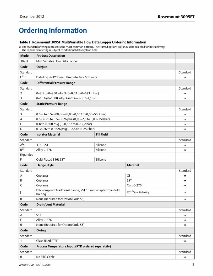
Table 1. Rosemount 3095F MultiVariable Flow Data Logger Ordering Information★ The Standard offering represents the most common options. The starred options (★) should be selected for best delivery.__The Expanded offering is subject to additional delivery lead time.
Model Product Description
3095F MultiVariable Flow Data Logger
Code Output
Standard Standard
H(1) Data Log via PC based User Interface Software ★
Code Differential Pressure Range
Standard Standard
2 0–2.5 to 0–250 inH2O (0–0,63 to 0–623 mbar) ★
3 0–10 to 0–1000 inH2O (0–2,5 mbar to 0–2,5 bar) ★
Code Static Pressure Range
Standard Standard
3 0.5-8 to 0.5–800 psia (0,03–0,552 to 0,03–55,2 bar) ★
4 0.5-36.26 to 0.5–3626 psia (0,03–2,5 to 0,03–250 bar) ★
C 0-8 to 0-800 psig (0–0,552 to 0–55,2 bar) ★
D 0-36.26 to 0-3626 psig (0-2,5 to 0–250 bar) ★
Code Isolator Material Fill Fluid
Standard Standard
A(2) 316L SST Silicone ★
B(2) Alloy C-276 Silicone ★
Expanded
F Gold-Plated 316L SST Silicone
Code Flange Style Material
Standard Standard
A Coplanar CS ★
B Coplanar SST ★
C Coplanar Cast C-276 ★
JDIN compliant traditional flange, SST 10 mm adapter/manifold bolting
SST, 7/16 — 20 Bolting ★
0 None (Required for Option Code S5) ★
Code Drain/Vent Material
Standard Standard
A SST ★
C Alloy C-276 ★
0 None (Required for Option Code S5) ★
Code O-ring
Standard Standard
1 Glass-filled PTFE ★
Code Process Temperature Input (RTD ordered separately)
Standard Standard
0 No RTD Cable ★
3www.rosemount.com

Rosemount 3095FT December 2012
1 RTD input with 12 ft. (3,66 m) of Shielded Cable (intended for use with conduit) ★
2 RTD input with 24 ft. (7,32 m) of Shielded Cable (intended for use with conduit) ★
7 RTD input with 75 ft.(22,86 m) of Shielded Cable (intended for use with conduit) ★
3 RTD input with 12 ft. (3,66 m) of Armored, Shielded Cable ★
4 RTD input with 24 ft. (7,32 m) of Armored, Shielded Cable ★
8 RTD Input with 75 ft. (22,86 m) of Armored, Shielded Cable ★
A RTD input with 12 ft. (3,66 m) ATEX/IECEx Flameproof Cable ★
B RTD input with 24 ft. (7,32 m) ATEX/IECEx Flameproof Cable ★
C RTD input with 75 ft. (22,86 m) ATEX/IECEx Flameproof Cable ★
Code Transmitter Housing Material Conduit
Standard Standard
A Polyurethane-covered Aluminum ½–14 NPT ★
B Polyurethane-covered Aluminum M20 � 1.5 (CM20) ★
J SST ½–14 NPT ★
K SST M20 � 1.5 (CM20) ★
Code Terminal Block
Standard Standard
A Standard ★
B With Integral Transient Protection ★
Code Display
Standard Standard
0 None ★
1 LCD Display ★
Code Bracket
Standard Standard
0 None ★
1 Coplanar SST flange bracket for 2-in. pipe or panel mount, SST bolts ★
2 Traditional Flange Bracket for 2-in. Pipe Mounting, CS Bolts ★
3 Traditional Flange Bracket for panel Mounting, CS Bolts ★
5 Traditional Flange Bracket for 2-in. Pipe Mounting, 300-Series, SST Bolts ★
6 Traditional Flange Bracket for panel Mounting, 300-Series, SST Bolts ★
8 SST Traditional Flange Bracket for 2-in. Pipe Mounting, 300-Series, SST Bolts ★
9 SST Traditional Flange Flat Bracket for 2-in. Pipe Mounting, 300-Series, SST Bolts ★
Code Bolts
Standard Standard
0 CS bolts ★
1 Austenitic 316 SST Bolts ★
N None (Required for Option Code S5) ★
Code Product Certifications
Standard Standard
0 None ★
A FM Explosion-proof, Dust Ignition-proof ★
C CSA Explosion-proof, Dust Ignition-proof, Division 2 ★
Table 1. Rosemount 3095F MultiVariable Flow Data Logger Ordering Information★ The Standard offering represents the most common options. The starred options (★) should be selected for best delivery.__The Expanded offering is subject to additional delivery lead time.
4 www.rosemount.com

Rosemount 3095FTDecember 2012
5www.rosemount.com
H ATEX Flameproof ★
P ATEX Dust ★
7 IECEx Flameproof ★
8 IECEx Dust ★
Code Engineered Measurement Solution (EMS)
Standard Standard
A Averaging Method: Time-weighted Formulaic Averaging Compressibility Factor ★
Options (Include with selected model number)
Code Configuration
Standard Standard
C1 Custom Configuration (requires completed Configuration Data Sheet) ★
Code Process Adapter
Standard Standard
DF 1/2-14 NPT Process Adapter, Type Determined by Selected Flange Material: Plated CS, SST, Cast C-276 ★
Code Material Traceability Certification
Standard Standard
Q8 Material Traceability Certification per EN 10204 3.1 ★
Code Calibration Certificate
Standard Standard
Q4 Calibration Certificate ★
Code Pressure Testing
Expanded
P1 Hydrostatic Testing with Certificate
Code Cleaning
Expanded
P2 Cleaning for Special Services
Code Integral Manifold
Standard Standard
S5(3) Assembly with Rosemount 305 Integral Manifold ★
Code Performance Class
Standard Standard
U3(4) Ultra for Flow: ±0.05% DP reading accuracy, up to 100:1 rangedown, 10 year stability, limited 12 year warranty
★
Typical Model Number 3095F H 2 3 A B A 1 1 A B 1 1 0 A A
(1) Communication based on Digital HART Protocol.
(2) Materials of Construction comply with metallurgical requirements highlighted within NACE MR0175/ISO 15156 for sour oil field production environments. Environmental limits apply to certain materials. Consult latest standard for details. Selected materials also conform to NACE MR0103 for sour refining environments.
(3) “Assemble-to” items are specified separately and require a completed model number.
(4) Ultra for Flow (Option U3) applicable for DP ranges 2 and 3 with SST isolator material and silicone fill fluid only.
Table 1. Rosemount 3095F MultiVariable Flow Data Logger Ordering Information★ The Standard offering represents the most common options. The starred options (★) should be selected for best delivery.__The Expanded offering is subject to additional delivery lead time.
Rosemount 3095FT December 2012
Specifications
Functional ServiceAGA 8 Natural Gas, AGA 3 Orifice PlatesConsult factory for other fluid and primary elementcombinations.
Differential SensorLimits
• Range 2: 0 to 250 inH2O (0 to 623 bar)
• Range 3: 0 to 1000 inH2O (0 to 2,49 bar)
Absolute SensorLimits
• Range 3: 0.5 to 800 psia (0,03 to 55,2 bar)
• Range 4: 0.5 to 3,626 psia (0,03 to 250 bar)
Gage PressureLimits
• Range C: 0 to 800 psig (0 to 55,2 bar)
• Range D: 0 to 3,626 psig (0 to 250 bar)
Over Pressure Limit0.5 psia (0,03 bar) to two times the absolute pressure sensor range up to a maximum of 3,626 psia (250 bar).
Static Pressure LimitOperates within specifications between static line pressures of 0.5 psia (0,03 bar) and the URL of the absolute pressure sensor.
Flow Calculations• 1992 AGA Report No. 3(1)
• API MPMS Chapter 14.3(1)
• GPA(1)
• Flange tap configurable per corresponding AGA calculations
• Pipe Tap configurable per corresponding AGA calculations
NOTEFlow calculations will cease when DP readings are below low flow cut off.
Compressibility Calculations• AGA Report No. 8
• API MPMS Chapter 14.2
• Gross or Detailed Characterization Method
Data Logging• Exceeds API MPMS 21.1
• Daily & Variable Logs have user selected time duration between 1-99 minutes
• Event Logs record alarms, configuration changes, and significant occurrences affecting flow calculation
• 50 days of daily logs maintained for user-selected process variables and calculated values when seven required API variables are logged.
• Logged files saved as ASCII file or comma separated value file.Daily Variable Log ParametersMaximum: DP, PT, and SPMinimum: DP, PT, and SPAverage: DP, PT, and SPTotal: Energy, Flow, and Flow TimeAverage: Energy Rate, Flow Rate, Integral Value, C', ZSpecific GravityHeating Value
Audit TrailExceeds API MPMS Chapter 21.1 standards for electronic flow measurement systems.
User Interface Software and Hardware Requirements• PC with CD-ROM Drive
• 4 MB RAM minimum
• Microsoft® Windows® 98, NT, 2000, or XP
• 2 MB of free hard disk space
OutputTwo-wire, constant 9.5mA current, data logging
Power SupplyExternal power supply required. Data Logger operates on terminal voltage of 7.5–35 Vdc with a constant average operating current of 9.5 mA.
(1) “Orifice Metering of Natural Gas and Other Related Hydrocarbon Fluids.” Third Edition, August 1992. Part 3 Natural Gas Applications. American Gas Association Report No. 3; American Petroleum Institute API 14.3; Gas Processor Association GPA 8185-92.
6 www.rosemount.com
Rosemount 3095FTDecember 2012
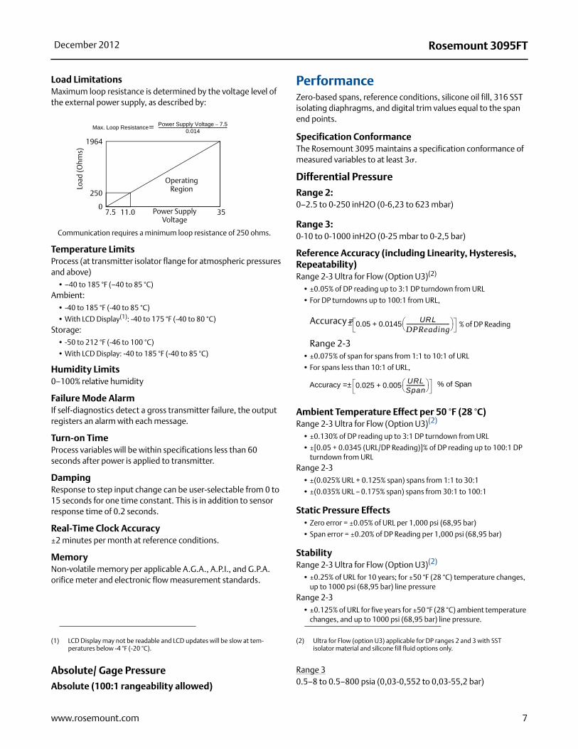
Load LimitationsMaximum loop resistance is determined by the voltage level of the external power supply, as described by:
Temperature LimitsProcess (at transmitter isolator flange for atmospheric pressures and above)
• –40 to 185 °F (–40 to 85 °C)Ambient:
• -40 to 185 °F (-40 to 85 °C)
• With LCD Display(1): -40 to 175 °F (-40 to 80 °C)Storage:
• -50 to 212 °F (-46 to 100 °C)
• With LCD Display: -40 to 185 °F (-40 to 85 °C)
Humidity Limits0–100% relative humidity
Failure Mode AlarmIf self-diagnostics detect a gross transmitter failure, the output registers an alarm with each message.
Turn-on TimeProcess variables will be within specifications less than 60 seconds after power is applied to transmitter.
DampingResponse to step input change can be user-selectable from 0 to 15 seconds for one time constant. This is in addition to sensor response time of 0.2 seconds.
Real-Time Clock Accuracy±2 minutes per month at reference conditions.
MemoryNon-volatile memory per applicable A.G.A., A.P.I., and G.P.A. orifice meter and electronic flow measurement standards.
Performance Zero-based spans, reference conditions, silicone oil fill, 316 SST isolating diaphragms, and digital trim values equal to the span end points.
Specification ConformanceThe Rosemount 3095 maintains a specification conformance of measured variables to at least 3�.
Differential Pressure
Range 2: 0–2.5 to 0-250 inH2O (0-6,23 to 623 mbar)
Range 3: 0-10 to 0-1000 inH2O (0-25 mbar to 0-2,5 bar)
Reference Accuracy (including Linearity, Hysteresis, Repeatability)Range 2-3 Ultra for Flow (Option U3)(2)
• ±0.05% of DP reading up to 3:1 DP turndown from URL
• For DP turndowns up to 100:1 from URL,
Accuracy =
Range 2-3• ±0.075% of span for spans from 1:1 to 10:1 of URL
• For spans less than 10:1 of URL,
Ambient Temperature Effect per 50 °F (28 °C)Range 2-3 Ultra for Flow (Option U3)(2)
• ±0.130% of DP reading up to 3:1 DP turndown from URL
• ±[0.05 + 0.0345 (URL/DP Reading)]% of DP reading up to 100:1 DP turndown from URL
Range 2-3 • ±(0.025% URL + 0.125% span) spans from 1:1 to 30:1
• ±(0.035% URL – 0.175% span) spans from 30:1 to 100:1
Static Pressure Effects• Zero error = ±0.05% of URL per 1,000 psi (68,95 bar)
• Span error = ±0.20% of DP Reading per 1,000 psi (68,95 bar)
Stability Range 2-3 Ultra for Flow (Option U3)(2)
• ±0.25% of URL for 10 years; for ±50 °F (28 °C) temperature changes, up to 1000 psi (68,95 bar) line pressure
Range 2-3• ±0.125% of URL for five years for ±50 °F (28 °C) ambient temperature
changes, and up to 1000 psi (68,95 bar) line pressure.
Absolute/ Gage Pressure
Absolute (100:1 rangeability allowed)
Range 30.5–8 to 0.5–800 psia (0,03-0,552 to 0,03-55,2 bar)
(1) LCD Display may not be readable and LCD updates will be slow at tem-peratures below -4 °F (-20 °C).
1964
250
07.5 11.0 Power Supply
Voltage35
Operating Region
Communication requires a minimum loop resistance of 250 ohms.
Max. Loop ResistancePower Supply Voltage 7.5–
0.014-------------------------------------------------------------------------=
Load
(Ohm
s)
(2) Ultra for Flow (option U3) applicable for DP ranges 2 and 3 with SST isolator material and silicone fill fluid options only.
0.05 0.0145URL
DPReading---------------------------------- +± % of DP Reading
% of Span0.025 0.005URLSpan--------------- +Accuracy =±
7www.rosemount.com

Rosemount 3095FT December 2012
Range 40.5–36.26 to 0.5–3,626 psia (0,03-2,5 to 0,03-250 bar)
Gage (100:1 rangeability allowed)Range C0–8 to 0–800 psig (0-0,552 to 0-55,2 bar)Range D0–36.26 to 0–3,626 psig (0-2,5 to 0-250 bar)
Reference Accuracy (including linearity, hysteresis, repeatability)
• ±0.075% of span for spans from 1:1 to 6:1 of URL
• For spans less than 6:1 rangedown
Ambient Temperature Effect per 50 °F (28 °C)• ±(0.05% URL + 0.125% of span) spans from 1:1 to 30:1
• ±(0.06% URL - 0.175% of span) spans from 30:1 to 100:1
Stability • ±0.125% of URL for five years for ±50 °F (28 °C) ambient temperature
changes, and up to 1000 psi (68,95 bar) line pressure.
Process Temperature (RTD)Specification for process temperature is for the transmitter portion only. Sensor errors caused by the RTD are not included. The transmitter is compatible with any PT100 RTD conforming to IEC 751 Class B, which has a nominal resistance of 100 ohms at 0 °C and = 0.00385. Examples of compatible RTDs include the Rosemount Series 68 and 78 RTD Temperature Sensors.
Range–40 to 185 °F (–40 to 85 °C). May be limited by the flow calculation characterization method.
Accuracy (including Linearity, Hysteresis, Repeatability)±1.0 °F (0.56 °C)
Ambient Temperature Effects±0.72 °F (0.40 °C) per 50 °F (28 °C)
Stability±1.0 °F (0.56 °C) for one year
Physical SecurityTransmitter security switch mounted on electronics board, when enabled prevents changes to transmitter security.User Interface Software provides three levels of password security, they are as follows:
• System Administrator (one password)
• Maintenance (three passwords)
• Operation (six passwords)
Electrical Connections½–14 NPT, M20 x 1.5 (CM20), PG-13.5
Process ConnectionsTransmitter
• ¼–18 NPT on 21/8-in. centers.RTD
• RTD dependent (see “Options” on page 12)
RTD Process Temperature Input100-ohm platinum RTD per IEC-751 Class B
Process Wetted PartsIsolating Diaphragms
• 316L SST or Alloy C-276Drain/Vent Valves
• 316 SST or Alloy C-276Flanges
• Plated carbon steel, 316 SST, or Alloy C-276Wetted O-rings
• Glass-Filled PTFE
Non-Wetted PartsElectronics Housing
• Low copper aluminumBolts
• Plated carbon steel per ASTM A449, Grade 5; or austenitic 316 SST
Fill Fluid• Silicone oil
Paint• Polyurethane
O-rings• Buna-N
Weight
Accuracy 0.03 0.0075URLSpan-------------- + % of span=±
Component Weight in lb (kg)Rosemount 3095FT Transmitter 6.0 (2.7)LCD Display 0.5 (0.2)SST Mounting Bracket 1.0 (0.4)12 ft (3.66 m) RTD Shielded Cable 0.5 (0.2)12 ft (3.66 m) RTD Armored Cable 1.1 (0.5)12 ft. (3.66 m) RTD ATEX/IECEx Cable 2.1 (0.9)24 ft (7.32 m) RTD Shielded Cable 1.0 (0.424 ft (7.32 m) RTD Armored Cable 2.2 (1.0)24 ft. (7.32 m) RTD ATEX/IECEx Cable 3.0 (1.4)75 ft (22.86 m) RTD Shielded Cable 1.9 (0.9)75 ft (22.86 m) RTD Armored Cable 7.2 (3.2)75 ft. (22.86 m) RTD ATEX/IECEx Cable
7.1 (3.2)
8 www.rosemount.com
Rosemount 3095FTDecember 2012
9www.rosemount.com
Product certifications
Approved Manufacturing LocationsRosemount Inc. — Chanhassen, Minnesota USA
European Directive InformationThe EC declaration of conformity for all applicable European directives for this product can be found on the Rosemount website at www.rosemount.com. A hard copy may be obtained by contacting our local sales office.
ATEX Directive (94/9/EC)Emerson Process Management complies with the ATEX Directive.
European Pressure Equipment Directive (PED) (97/23/EC)3095F_2/3,4/D Flow Transmitters — QS Certificate of Assessment - EC No. PED-H-100 Module H Conformity Assessment
All other 3095_ Transmitters/Level Controller \— Sound Engineering Practice
Transmitter Attachments: Process Flange - Manifold — Sound Engineering Practice
Electro Magnetic Compatibility (EMC) (2004/108/EC)3095FT Flow Transmitters — EN 61326:1997/ A1, A2, and A3
Ordinary Location Certification for Factory MutualAs standard, the transmitter has been examined and tested to
determine that the design meets basic electrical, mechanical, and fire
protection requirements by FM, a nationally recognized testing
laboratory (NRTL) as accredited by the Federal Occupational Safety and
Health Administration (OSHA).
Hazardous Locations Certifications
North American Certifications
FM Approvals
A Explosion Proof for Class I, Division 1, Groups B, C, and D. Dust-Ignition Proof for Class II, Division 1, Groups E, F, and G. Suitable for Class III, Division 1, indoor and outdoor (Type 4X) hazardous locations. Factory Sealed. Provides non-incendive RTD connections for Class I, Division 2, Groups A, B, C, and D. Install per Rosemount drawing 03095-1025.
Canadian Standards Association (CSA)
C Explosion Proof for Class I, Division 1, Groups B, C, and D. Dust-Ignition Proof for Class II, Division 1, Groups E, F, and G. Suitable for Class III, Division 1, indoor and outdoor hazardous locations, CSA enclosure Type 4X. Factory Sealed. Provides non-incendive RTD connection for Class I, Division 2, Groups A, B, C, and D. Approved for Class I, Division 2, Groups A, B, C, and D. Install in accordance with Rosemount Drawing 03095-1024.
European Certifications
H ATEX Flameproof Certificate Number: KEMA02ATEX2320X II 1/2 GEEx d IIC T5 (-50 °C Tamb 80 °C)
T6 (-50 °C Tamb 65 °C) 1180
Special Conditions for Safe Use (x):
The device contains a thin wall diaphragm. Installation, maintenance, and use shall take into account the environmental conditions to which the diaphragm will be subjected. The manufacturer’s instructions for installation and maintenance shall be followed in detail to assure safety during its expected lifetime.
P ATEX DustCertificate Number: KEMA02ATEX2321 II 1 DV = 55 Vdc MAXI = 23 mA MAXIP66
1180
IECEx Certifications
7 IECEx FlameproofCertificate Number: IECEx KEM 06.0018Zone 0/1 Ex d IIC T6 (-20 °C Ta 65 °C)Zone 0/1 Ex d IIC T5 (-20 °C Ta 80 °C)Vmax = 55 VdcImax = 23 mAdc
8 IECEx DustCertificate Number: IECEx KEM 06.0018Ex tD A22 T90°CIP66

Rosemount 3095FT December 2012
Dimensional drawings
Exploded View of 3095FT
Housing
Cover O-ring
Terminal Block
Cover
Housing Locking Screw
Electronics Board
Nameplate
Sensor Module
Coplanar Flange
OptionalFlange Adapters
Bolts
Drain/Vent Valve
Certification Label
RTD Connector
Process Flange O-ring
Flange Adapter O-ring
Module O-ring
10 www.rosemount.com
Rosemount 3095FTDecember 2012
11www.rosemount.com
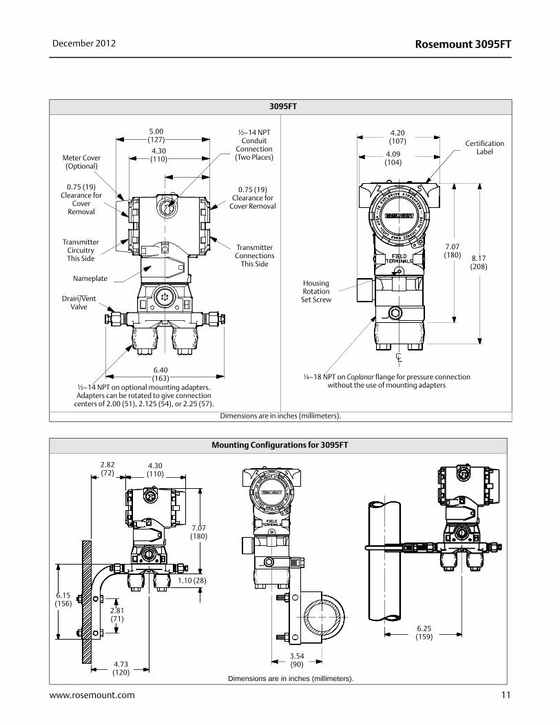
3095FT
Dimensions are in inches (millimeters).
Meter Cover(Optional)
0.75 (19)Clearance for
Cover Removal
TransmitterCircuitryThis Side
Nameplate
Drain/VentValve
½–14 NPT on optional mounting adapters. Adapters can be rotated to give connection
centers of 2.00 (51), 2.125 (54), or 2.25 (57).
6.40(163)
½–14 NPT Conduit
Connection (Two Places)
TransmitterConnections
This Side
5.00 (127)
4.30(110)
0.75 (19)Clearance for
Cover Removal
7.07(180) 8.17
(208)
¼–18 NPT on Coplanar flange for pressure connection without the use of mounting adapters
Housing Rotation
Set Screw
4.20 (107)
4.09(104)
Certification Label
Mounting Configurations for 3095FT
Dimensions are in inches (millimeters).
2.81(71)
2.82(72)
6.15(156)
4.30(110)
7.07(180)
1.10 (28)
4.73 (120)
3.54 (90)
6.25 (159)

Rosemount 3095FT December 2012
Options
Standard Configuration Unless otherwise specified, the transmitter is shipped as follows:
Custom Configuration (Option Code C1)If Option Code C1 is ordered, the customer specifies the following information for the 3095FT in addition to the standard configuration parameters.
Configuration Data Sheet (see rosemount.com): Gas composition parameters, contract hour, log parameters, LCD display parameters, meter run configuration parameters, low flow cut-off, passwords, static pressure tap location, static pressure measurement, damping, descriptor, message, and upper and lower trim points for each process variable.
TaggingThree customer tagging options are available:
• Standard SST tag is wired to the transmitter. Tag character height is 0.125 in. (3,18 mm),85 characters maximum.
• Tag may be stored in transmitter memory. Software tag (8 characters maximum) is left blank unless specified.
• Tag may be permanently stamped on transmitter nameplate upon request. Tag character height is 0.0625 in. (1,59 mm), 65 characters maximum.
• Software tag (8 characters maximum) is left blank unless specified.
Additional informationRosemount transmitters are available as fully assembled and factory calibrated flowmeters. Flowmeter Product Data Sheets are listed below:
Accessories
3095FT User Interface Software PackagesAll configurations are packaged separately.
Windows 98, NT, 2000, and XP• Single PC license: 03095-5100-0104
Site license: 03095-5100-0105
• Single PC license, Serial Port HART Modem and cables: 3095-5100-0102
• Single PC license, USB HART Modem and Cables (Requires Windows XP or 2000 Operating System): 03095-5100-0103
Communication Accessories
Engineering units:
Differential inH2O at 60 °F (All ranges)Absolute/gage psi (all ranges) Output: 9.5mA with Data LoggingFlange type: Specified model code optionFlange material: Specified model code optionO-ring material: Specified model code optionDrain/vent: Specified model code optionFlow Configuration Parameters:
Factory default
Software tag: (Blank)
• Orifice Plate Primary Element Systems: 00813-0100-4792Rosemount 1495 Orifice Plate
Rosemount 1496 Flange UnionRosemount 1497 Meter Section
Item Description Part NumberSerial Port HART Modem and Cables Only
03095-5105-0001
USB Port HART Modem and Cables Only 03095-5105-0002
12 www.rosemount.com

Rosemount 3095FTDecember 2012
13www.rosemount.com
Rosemount 3095FT00813-0100-4015 Rev GB
Product Data SheetDecember 2012
Emerson Process ManagementRosemount Inc.8200 Market BoulevardChanhassen, MN 55317 USAT (U.S.) 1-800-999-9307T (International) (952) 906-8888F (952) 906-8889www.rosemount.com
Emerson Process ManagementBlegistrasse 23P.O. Box 1046CH 6341 BaarSwitzerlandT +41 (0) 41 768 6111F +41 (0) 41 768 6300www.rosemount.com
Emerson Process Management Asia Pacific Pte Ltd1 Pandan CrescentSignapore 128461T +65 6777 8211F +65 6777 0947Service Support Hotline: +65 6770 8711Email: [email protected]
Emerson Process ManagementBlegistrasse 23P.O. Box 1046CH 6341 BaarSwitzerlandT +41 (0) 41 768 6111F +41 (0) 41 768 6300www.rosemount.com
Emerson Process ManagementBlegistrasse 23P.O. Box 1046CH 6341 BaarSwitzerlandT +41 (0) 41 768 6111F +41 (0) 41 768 6300www.rosemount.com
Emerson Process ManagementBlegistrasse 23P.O. Box 1046CH 6341 BaarSwitzerlandT +41 (0) 41 768 6111F +41 (0) 41 768 6300www.rosemount.com
Standard Terms and Conditions of Sale can be found at www.rosemount.com\terms_of_saleThe Emerson logo is a trade mark and service mark of Emerson Electric Co.Rosemount and the Rosemount logotype are registered trademarks of Rosemount Inc.PlantWeb is a registered trademark of one of the Emerson Process Management group of companies.HART and WirelessHART are registered trademarks of the HART Communication FoundationModbus is a trademark of Modicon, Inc.All other marks are the property of their respective owners.© 2012 Rosemount Inc. All rights reserved.


