
DESIGN AND ANALYSIS OF HYDRAULIC SYSTEM
FOR FIRE FIGHTING MACHINE
RODDY ANAK RANGGAU
UNIVERSITI TEKNIKAL MALAYSIA MELAKA
DESIGN AND ANALYSIS OF HYDRAULIC SYSTEM
FOR FIRE FIGHTING MACHINE
RODDY ANAK RANGGAU
This thesis is submitted to the Faculty of Mechanical Engineering, in partial fulfillment
of the partial requirement for the
Bachelor of Mechanical Engineering (Thermal Fluid)
FACULTY OF MECHANICAL ENGINEERING
UNIVERSITI TEKNIKAL MALAYSIA MELAKA (UTeM)
(APRIL 2009)

ii
DECLARATION
“I hereby declaration that I have read through this thesis and found that it has comply the
partial fulfillment for awarding the degree of Bachelor Mechanical Engineering
(Thermal Fluid)
Signature : …………………………..
Supervisor : Mr. Mohd Rizal Alkahari
Date : …………………………..
iii
DECLARATION
“I hereby declaration that this thesis is my original work except for questions and
citations, which have been duly acknowledgement
Signature : …………………………..
Name : Roddy Anak Ranggau
Date : …………………………..

iv
ACKNOWLEDGEMENT
All praises be to God for give me a bless to completed my final year project. My
deepest appreciation to my first supervisor Mr. Mohd Rizal Alkahari and second
supervisor who have been very patient and committed in giving me the knowledge and
guidance in completing this report this whole time. Another gratitude for other lecturer
that keep helping and involved in my dissertation and others. Not to forget, my parent,
my brother who support me from the bottom to top through this year. Thank for their
concern, encouragement and understanding. Lastly, my fellow friends that always give
me some advice and knowledge to fulfill this report.

v
ABSTRACT
Fire fighting machine is a newly developed machine design where its function is
to reduce the fire fighter risk in the dangerous situations. This fire fighting machine is
operated using joystick, which is controlled by the fire fighter. A new dozer blade is
designed and to be installed on the existing fire fighting machine. The dozer blade is
used to move or clear object and save life by carry the victims away from danger during
rescuing process. Besides that, this machine is designed to be connected to fire hydrant
which is high in pressure in terms of it. The machine is capable to operate and monitor
remotely for danger area which have cooling acetylene and other flammable cylinders.
By utilize the decontamination materials that containing Chemical, Biological, Radiation
or Nuclear Incidents which is easy to explode can be removed without endanger the fire
fighter. The dozer blade is designed to save victim retrieval or removal from danger
areas and moving flammable cylinders away from this danger. This machine is useful in
the workshop, factory, power plants, tunnels, warehouses and in the building where fire
fighting process is very risky.
vi
ABSTRAK
Mesin memadam kebakaran adalah satu rekaan baru untuk menolong dan
mengurangkan bebanan atau risiko ahli bomba didalam keadaan yang berbahaya. Mesin
memadam kebakaran ini berfungsi atau dikawal mengunakan joystick yang disambung
kepada mesin. Joystick ini akan dikawal oleh ahli bomba itu sendiri. Satu rekaan baru
iaitu “dozer blade” akan ditambah kepada mesin memadam kebakaran ini. “Dozer
blade” ini berfungsi untuk mengerakan objek atau memberi laluan dan menyelamatkan
mangsa kebakaran, iaitu dengan membawa mangsa ke tempat yang lebih selamat
daripada bahang kebakaran. Selain itu, mesin memadam kebakaran ini membantu ahli
bomba dengan memegang paip bomba yang bertekanan tinggi dan meninjau tempat
kebakaran dari jarak jauh. Mesin ini membantu meninjau dari jarak 200 meter dari
tempat kebakaran seperti “cooling acetylene”, silinder mudah meletup, bahan kimia,
bahan biologi dan bahan radiasi atau kejadian nuclear tanpa membahayakan nyawa ahli
bomba. Rekaan “dozer blade” berfungsi memyelamat atau membawa mangsa kebakaran
dan juga bahan mudah meletup seperti “cooling acetylene” dan silinder mudah meletup
ke tempat yang lebih selamat. Mesin memadam kebakaran ini amat sesuai digunakan di
bengkel, kilang, pusat penjanaan tenaga, terowong dan dalam bangunan.

vii
TABLE OF CONTENTS
CHAPTER CONTENT
PAGE
DECLARATION
ii.
ACKNOWLEDGEMENT
iv.
ABSTRACT v.
ABSTRAK vi.
TABLE OF CONTENT Vii
LIST OF TABLE xi.
LIST OF FIGURE xii.
LIST OF SYMBOL xiv.
ANNOTATION xv.
LIST OF APPENDIXES
xvi.
CHAPTER 1 INTRODUCTION
1.1 Background Study
1
1.2 Problem Statement
2
1.3 Objectives of Project
3
1.4 Scope of Project
3

viii
CHAPTER 2 LITERATURE REVIEW
2.1 Development in Technology of Firefighting
Machine
4
2.2 Product Review
2.2.1 The Washremote
2.2.2 The Firemote
2.2.3 The Luf 60
2.2.4 The Jelka-4
2.2.5 The Firefighting Robot
2.2.6 The Firefighting Machine
5
6
7
8
9
10
11
2.4 Comparison of Firefighting Machines
12
CHAPTER 3 CONCEPTUAL DESIGN AND DEVELOPMENT
3.1 The Design
3.1.1 Problem Formulation
3.1.2 Concept Design
3.1.3 Design Configuration
3.1.4 Design Parameter
14
16
17
18
19
3.2 Product Design Specification (PDS)
20
3.3 Conceptual Design Development
3.3.1 Morphological Chart
3.3.2 Concept Screening and Scoring
23
24
24
3.4 Dozer Blade Design Structure
26

ix
3.4.1 Morphological Chart for Dozer Blade
Design Structure
3.4.2 Concept Idea Generation for Dozer Blade
Design Structure
3.4.3 Concept Scoring for Dozer Blade Design
Structure
26
28
33
CHAPTER 4 DOZER BLADE STRUCTURE
4.1 Hydraulic Cylinders 35
4.2 Hydraulic Pumps
37
4.3 Electric Motors
39
4.4 Control Valves
40
4.5 Hydraulic Accessories
4.5.1 Hydraulic Reservoirs
4.5.2 Filters
4.5.3 Hydraulic Pipes, Hoses and Fitting
4.5.3.1 Hydraulic Pipes and Tubes
4.5.3.2 Hydraulic Hoses
4.5.3.3 Hydraulic Fitting
41
41
42
43
44
44
46
4.6 Concept for the hydraulic system
47
CHAPTER 5 HYDRAULIC ANALYSIS
5.0 Discussion 48
x
5.1 Procedure to Design a Hydraulic System
5.1.1 Procedure to Design a Hydraulic System using
Individual Selected Part
5.1.2 Procedure to Design a Hydraulic System using
Hydraulic Power Packs
49
49
51
5.2 Calculation
5.2.1 Calculation (Individual Part Selections)
5.2.2 Calculation (Hydraulic Power Packs)
53
53
66
5.3 Hydraulic Circuit
5.3.1 Hydraulic Circuit Components for Dozer
Blade
5.3.2 Hydraulic Circuits System Process of
Dozer Blade
5.3.3 Hydraulic Circuit Component for
Telescopic Scissors
5.3.4 Hydraulic Improvement Circuits
(Telescopic Scissors)
69
70
72
74
78
CHAPTER 6 ANALYSIS OF FIRE FIGHTING MACHINE
6.0 Fire Fighting Machine
6.1 Mobility
80
82
6.1.1Gruebler’s Equation 82

xi
6.2 Dozer Blade
6.2.1 Dozer Blade Gruebler’s Equation
6.2.2 Dozer Blade Positioning
84
84
85
6.3 Telescopic Scissors
6.3.1 Telescopic Scissors Gruebler’s Equation
6.3.2 Telescopic Scissors Positioning
88
88
90
CHAPTER 7 CONCLUSION AND RECOMMENDATION
7.1 Recommendation
94
7.2 Conclusion
95
REFERANCES
96
BIBLIOGRAPHY
98
APPENDIXES
99
xi
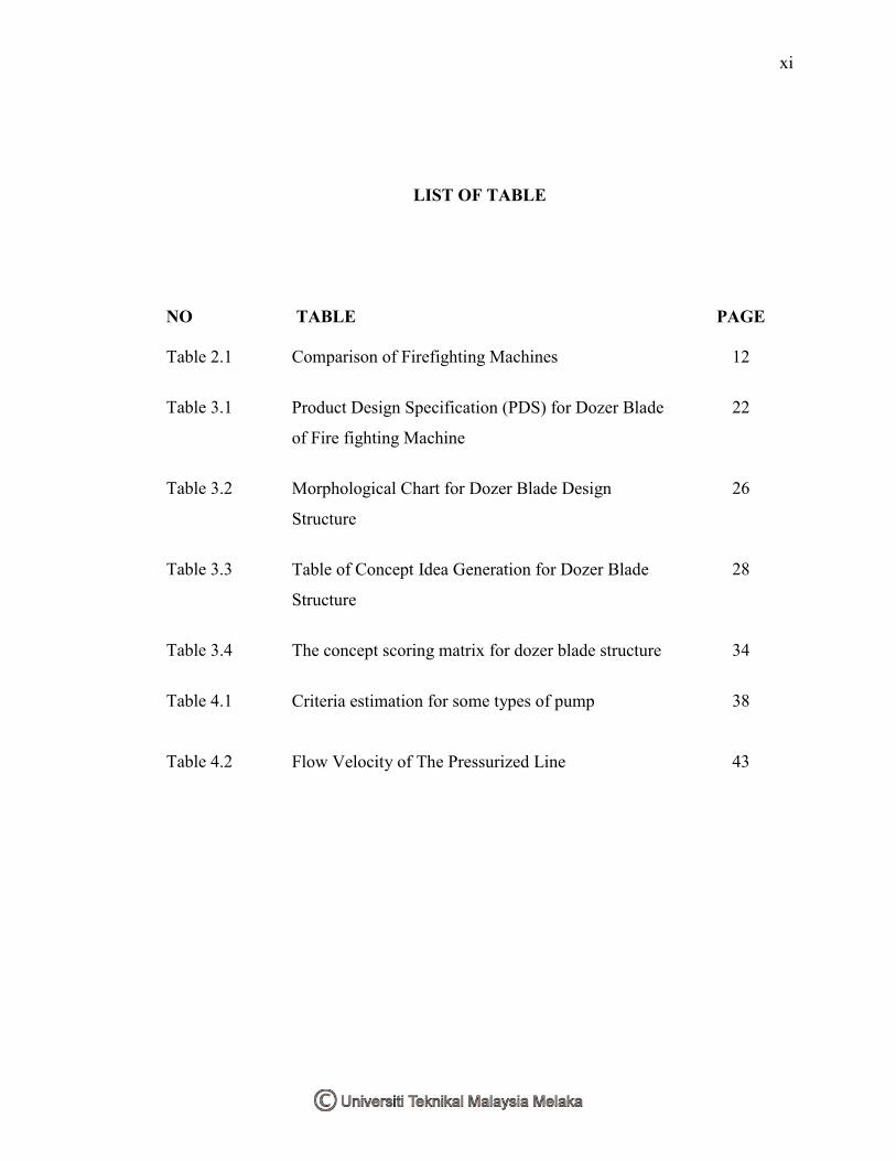
LIST OF TABLE
NO TABLE
PAGE
Table 2.1 Comparison of Firefighting Machines
12
Table 3.1 Product Design Specification (PDS) for Dozer Blade
of Fire fighting Machine
22
Table 3.2 Morphological Chart for Dozer Blade Design
Structure
26
Table 3.3 Table of Concept Idea Generation for Dozer Blade
Structure
28
Table 3.4 The concept scoring matrix for dozer blade structure
34
Table 4.1 Criteria estimation for some types of pump
38
Table 4.2 Flow Velocity of The Pressurized Line
43

xii
LIST OF FIGURE
NO TABLE
PAGE
Figure2.1 The Washremote
6
Figure 2.2 The Firemote
7
Figure 2.3 The LUF60 8
Figure 2.4 The Jelka-4 9
Figure 2.5 Firefighting Robot 10
Figure 2.6 The Firefighting Machine 11
Figure 3.1 Five design phase 15
Figure 3.2 The Concept Design Evaluation
25
Figure 3.3 Conceptual Design 1 29
Figure 3.4 Conceptual Design 2 30
Figure 3.5 Conceptual Design 3
31
Figure 3.6 Conceptual Design 4
32
Figure 3.7 Flow chart procedure for the concept scoring
evaluation
33
Figure 4.1 Double Acting Cylinder Design
36
Figure 4.2 Various Cylinder Mountings
37
Figure 4.3 Vane Pump Operation
38

xiii
Figure 4.4 Y2 Series Aluminum 3
39
Figure 4.5 Reservoir Construction
41
Figure 4.7 Typical Hose Mountings
44
Figure 4.8 Assembly of Flexible Hoses
45
Figure 4.9 Types of Flexible Hoses
45
Figure 4.10 Typical Hydraulic Fittings
46
Figure 4.11 Sample Circuit of Power Packs
47
Figure 5.1 Hydraulic Circuits 69
Figure 5.2 Dozer Blade (Cylinders) 70
Figure 5.3 Hydraulic Component (Dozer Blade) 70
Figure 5.4 Dozer Blade Circuit (Extend) 72
Figure 5.5 Dozer Blade Circuit (Retract) 73
Figure 5.6 Telescopic Scissors (Cylinders) 74
Figure 5.7 Hydraulic Component (Telescopic Scissors) 75
Figure 6.1 Fire Fighting Machine 81
Figure 6.2 Mechanism and Structure with Varying Mobility 83
Figure 6.3 Dozer Blade 84
Figure 6.4 Kinematics Diagram (Dozer Blade) 84
Figure 6.5 Dozer Blade Side View (Unit Centimeters) 86
Figure 6.6 Retract Position (Dozer Blade) 87
Figure 6.7
Extend Position (Dozer Blade)
87

xiv
Figure 6.8 Telescopic Scissors 88
Figure 6.9 Kinematics Diagram (Telescopic Scissors) 89
Figure 6.10 Telescopic Scissors Side View (Unit Centimeters) 90
Figure 6.11 Retract Position of Cylinder 3 (Telescopic Scissors) 91
Figure 6.12 Extend Position of Cylinder 3 (Telescopic Scissors) 91
Figure 6.13 Retract Position of Cylinder 1 (Telescopic Scissors)
92
Figure 6.14 Extend Position of Cylinder 1 (Telescopic Scissors)
92
Figure 6.15 Retract Position of Cylinder 2 (Telescopic Scissors)
93
Figure 6.16 Extend Position of Cylinder 2 (Telescopic Scissors)
93

LIST OF SYMBOL
AD
Assembly Design
CAE
Computer Aided Engineering
PDS Product Design Specification
UTeM Universiti Teknikal Malaysia Melaka
SINTEF The Foundation for Industrial and Scientific Research
TDM Total Design Method

xv
ANNOTATION
Q = Flow
n = revs per second
V stroke = swept volume in m3
η vol = volumetric efficiency
P = Power in Watt (Nm/s)
Δ p = pressure difference over pump in N/m2
η mech, hydr = mechanical/hydraulic efficiency
Fe = Extension Force
Pp = Pressure Piston
Ap = Piston Area
Ar = Rod Area
Fr = Retraction Force
Pa = Pressure on Annular Side
Tt = Theoretical Torque
Qt = Theoretical flow rate
TT = Actual torque delivery by motor
TA = Torque motor should theoretical deliver
o = actual power delivery by motor / actual power delivery to motor
HL = Head loss
Le = Equivalent length
extF = Cylinder Extending Force
prP = Working Pressure

xvi
K = Buckling load
KS = Free buckling length
E = Elasticity Module
J = Moment of Inertia
S = Safety Factor
pn pn = Pump Rotation Speed
voln = Volumetric Efficiency
xvi
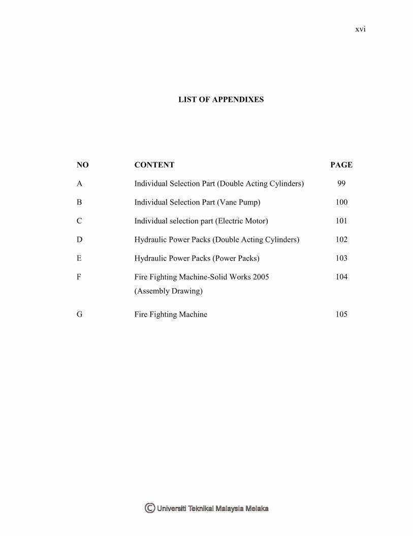
LIST OF APPENDIXES
NO CONTENT
PAGE
A Individual Selection Part (Double Acting Cylinders) 99
B Individual Selection Part (Vane Pump) 100
C Individual selection part (Electric Motor) 101
D Hydraulic Power Packs (Double Acting Cylinders) 102
E Hydraulic Power Packs (Power Packs) 103
F Fire Fighting Machine-Solid Works 2005
(Assembly Drawing)
104
G Fire Fighting Machine 105

1
CHAPTER 1
INTRODUCTION
1.1 Background Study
Firefighting is a process of act to avoid from destroying property, danger human
life and environment. A fireman jobs is to fights these fires to prevent destruction of life,
property and the environment. Fireman usually used fire engines, tools and equipments
to fights these fires. Most of the tools and equipment are manually operated. The new
era of technology, the fireman have an efficient way to fight fire with the new design of
improvement on tools and equipment.
Remote firefighting machine is a newly design machine that is creates to reduce
risk for human especially the fireman who rescuing in fights fire. It used to help fireman
to carry the hose without fireman having to set up or operate monitors in danger areas.
The main function for this design is a remotely control the machine and replace the
fireman in the dangerous place. It used same concept with fire fighting engine using the
fireman hydrant. The remote firefighting machine is connecting with the fireman hose to
operate and the machine carries the hose and sprays it onto the fire area by using remote
to control it. This machine is useful in the emergency situation, in the jungle and small
building or spaces.
Besides, the machine is help to victim retrieval or removal from danger areas,
moving flammable cylinders into a location where it‟s associated exclusion zone causes
2
less disruption and crowd control in civil disturbance situations. The ex rated electrical
system for operation in Zone 1 hazardous areas. Zone 1 is a place of thing easy to
explode for example the power plant. The job needs a lot of number fireman to do. The
new design of tools or machine is important to dealing of this kind of problems and it
can reduce the number of people. The machine design can enter the refineries areas and
the small spaces. For example, a version that can fit through aircraft emergency exits in
the event of a passenger airliner fire or buildings which is not suitable for human to do
the jobs.
1.2 Problem Statement:
Mostly, people doesn‟t know the danger of being fireman, their risk their own
life to saving people life who are their even don know or meet before. Most of the job of
the fireman are danger and can sacrifice their own life. The problem that always
encounters are entering the exclusion zones which is cooling acetylenes and other
flammable cylinders which might be dangerous, decontamination in Chemical,
Biological, Radiation or Nuclear Incidents. The fireman needs to fast response to the
situation without danger they own life.
3
1.3 Objectives of Project:
The objectives of the project are:
1. To improve the current design of hydraulic system of fire fighting machine.
2. To design a dozer blade for obstacle removal and rescuing
3. To design a hydraulic system to be used in rescuing process related to the fire
fighting machine.
.
1.4 Scopes of Project:
The scopes of the project are:
a. To conduct literature review on current fire fighting technology.
b. To identify current problems in fire fighting process.
c. To identify current problems in existing design.
d. To analyze the proposed design.
e. To analyze the hydraulic circuit of dozer blade and telescopic scissor.
f. To analyze the kinematics analysis and mechanism of telescopic scissor and dozer
blade.

4
CHAPTER 2
LITERATURE REVIEW
2.1 Development of Technology in Firefighting Machine:
In the research, the development of technology on firefighting is in progress
around the world. Most of the tools and equipments are manually operated by the
fireman. In the new era of technology, the advances technology of firefighting machines
is most conquered by the Western Country.
They had created a machine to reduce a number of firemen to fight fire in
dangerous situations. Besides, the machine also reduce the fireman risk, which are
involve in cooling acetylene, flammable cylinders and exclusion zone. It helps the
fireman with water or foam without fireman has to set up or operate monitors in danger
areas. This kind of machine really helps a lot in the rescuing and to fight fire in the
building or in the jungle difficult for fireman.
Western Country for example had made a machine that operates using remote
control to do the fireman jobs. Their have sell the machine to the fire department at other
countries. Example, United Kingdom with the product of The Washmote, a remotely
operated vehicle for surface washing and decontamination and The Firemote, a remotely
controlled mobile Fire fighting monitor, which is research funded by DTI through
SEEDA from Ryland Research Limited Company.


![Rahsia Bisnes Online Meletup - norfazilah.comnorfazilah.com]Rahsia_Bisnes... · ingin memulakan perniagaan online di facebook atau mereka yang sudah memulakannya tetapi belum berjaya.tidak](https://cdn.vdocuments.mx/doc/165x107/5a70260f7f8b9aac538bab14/rahsia-bisnes-online-meletup-norfazilahcom-norfazilahcomrahsiabisnespdf.jpg)

