

�������������
n ��� �������
2
��
������
How Safe Is Safe Enough?
Enough?
Enough?

�������
n ��������������� ���������
3
���
�����
�� �����
�������Safe Enough!
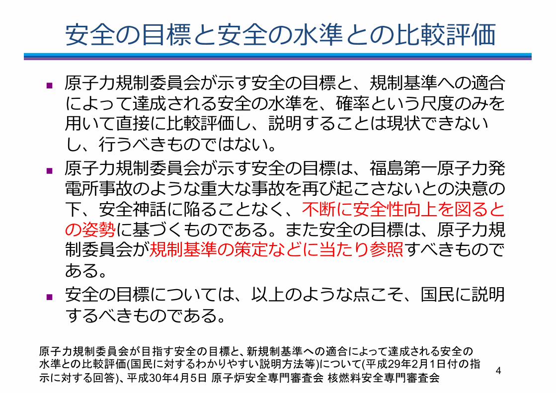
=9�7g�=9�JW��]kfPn ;/2Y>O6'�Q�=9�7g��Y>NW��h,� ��aB#"=9�JW$�U[���l5��$8��Rb�]kfP��`4�"��C^������*����������
n ;/2Y>O6'�Q�=9�7g��ZEI);/2-MA+e� ��L%�+e$T�_����1?�3�=9SH�j"����:\�=9@G($d"��cV�N������"���=9�7g��;/2Y>O6'�Y>NW�K.���<�!Xi�������"�
n =9�7g������F(� ��D �&0�`4�"������"�
4
���+� �5'�7��='�;2�+��$>=0�<@8:/�6CB��="$;= .,�(�!<�7BD4A?73-��#))<93:(��29�2�1��=�(<�7B*)2��30�4�5���%���1����&����1���

����� ����
5
�������������� �
�� ����
��9�����A�@6:�
'���:#�879�2?�
��;"�A�-4&�
��:�#93-4,1(*�). 0(�*�).5��1@=:
�)(�1</58-
+9"�A�-4;-8-
0>8@�����'�:$% �
'��� ��:!�
Safe Enough?
���������
6
������
���
��� �
� ��
������
����
���������

GKI*!��YC�41�/4n 3+-&?7�fW���'.,'� ������T�,��(���USNRC�VIA (Value Impact Analysis��0H��
n A Value-Impact Assessment of Alternate Containment Concepts, NUREG/CR-0165 (1978)n cAe<)�g9�[h`6�����F_ES;^PX=N*�!��5\�WASH-1400�B%�
n :M�8>��UZ�2]8>�Lbn �UZ�F_ES�2]8>dQ
n 8>^-�@;n F_ES�ER@;n cAe<$V)�F_ES "�n cAe<$V)�F_ES�g9h`n F_ESDJ^-�O.n cAe<$V)�[h`6���a#
7
D.D. Carlson, J.W. Hickman, SAND 77-1344, NUREG-CR-0165, June 1978
CHAPTER IV. DESIGN ALTERNATIVE DESCRIPTIONS
For each design alternative selected for the value-impact assessment, design goals were established. The design goals were selected to meet two criteria: (1) that they be feasible with current technology, and (2) that they result in the most favorable value-impact position for the design alternative. Each design alternative and its design goals are described below.
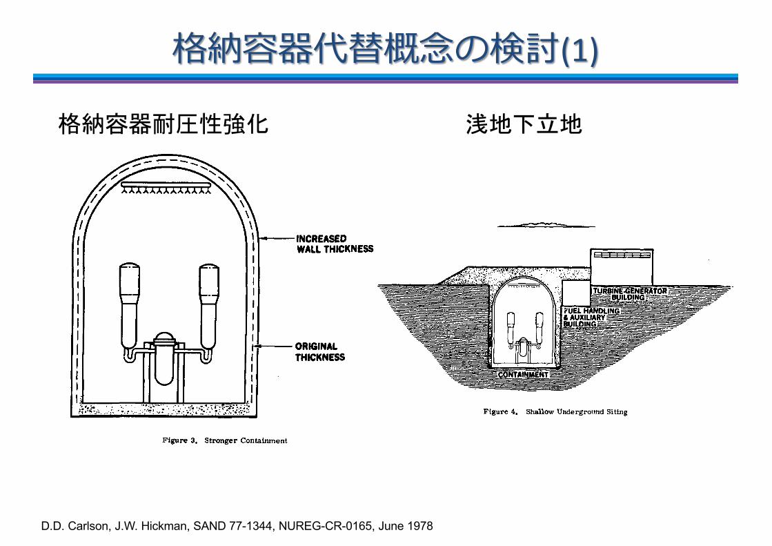
Stronger Containment
To increase the pressure capabilities of containment, the study examined the alternative of constructing a stronger containment by increasing the wall thickness. This alternative is i l lus-trated in Figure 3.
INCREASED WALL THICKNESS
ORIGINAL THICKNESS
Figure 3. Stronger Containment
Accident sequences resulting in overpressure failure can be divided into two categories. First are those loss of coolant accident (LOCA) sequences in which the containment spray systems fall but the emergency core cooling system <ECCS) operates. For these sequences, the containment
25
pressure builds following a LOCA and may reach several hundred psi. In this case, containment overpressure is expected to precede core melt. In the other case, both the cont3inment heat removal systems and the ECCS fail during injection or recirculation. For these sequences, core melt tends to precede containment overpressure failure. The pressure may rise as high as about 120 psia, but generally melt-through or condensation on cold surfaces will limit the pressure so that overpressure failure is not certain. It is believed to be very difficult to design a containment to withstand the several hundred psi pressures of the first category of accidents. Therefore, the design goal for the stronger containment was to contain the second category of accidents; the design pressure was set at 120 psia estimated to result in an approximate doubling of the thickness of the walls. At this design pressure, the containment should be able to withstand the pressure generated in all dominant overpressure sequences in the Reactor Safety Study except those LOCA sequences in which the containment spray systems fail but the ECCS operates.
Shallow Underground Siting
The shallow underground siting alternative, illustrated in Figure 4, was assumed to involve placing a standard containment under about 30 feet of overburden, thus increasing the pressure capabilities of the structure due to the lithostatic pressure of the overburden. The turbine generator building was assumed to be above grade. Shallow underground siting alternatives are currently under consideration in Germany, Their designs, however, entail a much larger con-tainment volume. This study assumed the same containment volume as a surface plant.
Figure 4. Shallow Underground Siting
Deep Underground Siting
The deep underground siting alternative considered in this study is shown in Figure 5. It was assumed that the top of the containment structure would be at least 100 feet underground with the turbine generator building located c u the surface. The pressure capabilities of the containment
26
���������(1)
��� ���� ����

Figure 6. Increased Containment Volume
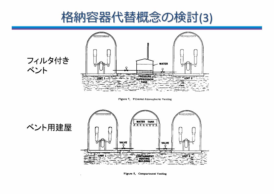
Filtered Atmospheric Venting
The filtered atmospheric venting alternative is illustrated in Figure 7. This alternative assumed use of a pressure suppression pool, envisioned as being placed external to the contain-ment, to reduce the pressure in containment following a core-meltdown accident. Containment gases were assumed to be vented to the atmosphere following filtration by the water in the tank. It is assumed that venting would be achieved automatically upon sensing a pressure which is near but slightly above the containment design pressure (~60 psia). The goal would be to assure , for the range of significant meltdown accidents, that the containment design pressure would not be greatly exceeded. It is assumed that relief valves would open under the increased pressure; thus, the con-tainment would remain isolated unless a significant buildup in pressure occurred. Redundant systems and backup manual control would probably be advisable for these valves. The tank would contain enough water to allow condensation of all 1he steam generated. To ensure that large bubbles do not form, thus reducing the effectiveness of the filter, the steam should probably enter the tank through many small openings. It was assumed that the water would remove almost all of the radio-active contaminants except for the noble gases which would be vented out a stack.
Compartment Venting
This alternative, shown in Figure 8, is similar, in principle, to the vacuum building UBed in the Canadian CANDU design. For this alternative, a separate, high pressure (60 psla) containment s t ructure was assumed to be constructed, one per reactor site, Into which the containment atmo-sphere would be vented in the event of a core-meltdown accident. As in the filtered atmospheric
D.D. Carlson, J.W. Hickman, SAND 77-1344, NUREG-CR-0165, June 1978
would be enhanced by the lithostatic pressure of the overburden although there would still be several access passages to the surface. This alternative would involve construction of a contain-ment similar in size and design requirements to a surface structure with modifications to enable it to withstand the external load exerted by the overburden. All passageways exiting the contain-ment would be sealed during operation, and those passageways to the surface would be sealed at the surface in the event of an accident.
Figure 5. Deep Underground Siting
Increased Containment Volume
Another means of increasing the gas containment capabilities of a PWR containment would involve increasing the containment volume as illustrated in Figure 6, For this alternative, it was assumed that the design pressure would remain at 60 psia and that the volume would be approxi-mately doubled. To accommodate such an increase in volume, it is assumed that the wall thickness would be increased by about one foot. This alternative would be expected to achieve the same bene-fits discussed in the stronger containment alternative. That is , overpressure failures would not be significantly inhibited for those LOCA accidents in which the containment spray systems fail but the ECCS operates; for other core melt accidents overpressure failure of the containment would not be expected.
27
���������(2)
���� �������
���������(3)
venting alternative, venting was assumed to be achieved automatically by opening valves in the con-necting piping when containment pressure r ises to near design pressure. The auxiliary containment was assumed to be equipped with an elevated water tank which would spray by gravity feed upon sensing a rise in pressure . This spray would condense the incoming steam and allow further pressure reduction in both structures. Spray openings would be sized to spray until the molten core would be expected to have melted through the base imt , thus relieving containment pressure to the ground. The likelihood of overpressure failure would be expected to be greatly reduced.
Figure 7. Filtered Atmospheric Venting
Figure 8. Compartment Venting
�������
�����

���������(4)Thinned Base Mat
The thinned base mat alternative is illustrated in Figure .9. Current plants have concrete base mats approximately ten feet thick. While no optimal thickness was determined, the concrete under the reactor pressure vessel does r,ot appear to support any loads, so a significant reduction in thickness of the base mat appears feasible. In addition to hastening the melt-through process and thus reducing the overpressure failure probability of selected accident sequences, less noncon-densable gases, in particular carbon dioxide and hydrogen, would be expected to be produced from the interaction of the core on the concrete.
Figure 9. Thinned Base Mat
Evacuated Containment
Many plants currently operate at pressures slightly subatinospheric to reduce the normal leakage of gases from the containment. The Surry reactor examined in the Reactor Safety Study operates at about 10 psia. To reduce the likelihood of hydrogen burning, the evacuated containment alternative, shown in Figure 10, was assumed to have about a 5 psia containment, resulting in about 1 psia partial pressure O Thus, a significant reduction of the chance of hydrogen ignition would be expected. Reduction of the internal pressure to this level should be possible using a steam powered vacuum pump.
Double Containment
The double containment alternative, illustrated in Figure 11, is used frequently in existing containments. The outer wall, however, generally can withstand only minor pressure differentials. Its primary function being to protect the inner wall from external missiles. This study examined
30
strengthening the outer wall such that it would have a gas containment capability equivalent to the inner wall. Thus, failure of the inner wall would not necessarily lead to an escape of radioactivity. In the case of overpressure failure, however, it is likely the outer wall would soon be subjected to pressures similar to those exerted on the inner wall and, as a result, would also fail. To ensure that the concept of double containment was judged on its own meri ts , the volume within the outer wall was msde equivalent to current plants; that is, no benefits resulting from increasing the volume of the containment were allowed. Despite this restriction, it appears that this alternative would offer some benefits in event of internal missiles and could reduce the likelihood of containment iso-lation failure because of redundant seals on the penetrations.
31
��������������
���� � ���

Value Impact ��
CHAPTER VII. CONCLUSIONS
The results of this study are presented to the form of a qualitative value-impart matrix shown in Figure 14. From this matrix it is apparent that, among the alternatives considered, filtered atmospheric venting offers the greatest potential for reducing public risk for the least im-pact. Compartment venting and deep underground siting offer similar potential for reducing public risk but greater impacts. Evacuated containment and thinned base mat, while being low impact alternatives, offer little potential for reducing public risk. Combinations of alternatives were not considered. Each alternative was evaluated on its own merits rather than attempting to idenfity an optimal design combination.
1 EVACUATED CONTAINMENT
CURRENT DOUBLE SHALLOW SURFACE CONTAINMENT UNDERGROUND
1 ' PLANTS TH INNED SITING BASE MAT
at 7 STRONGER
noN
i CONTAINMENT
noN
i
INCREASED
u CONTAINMENT J o UJ
VOLUME J o UJ K
FILTERED DEEP ATMOSPHERIC COMPARTMENT U N D E R G R O U ND
'
VENTING VENTING SITING
-•INCREASE IN COST
Figure 14. Qualitative Value-Impact Matrix
To place these results in proper perspective, several points need to be made. These results are baeed primarily on risk insights from WASH-1400 which considered only two reactors. Although efforts have been made to eliminate atypical characteristics of these plants, the results of this study «hould be treated only as indicative of what might be found in a broader study. The basic
47

0���Value-Impact�8
n Value��1�����!���RSS�&(��
13
t
TABLE XXI
Potential Impacts of Alternate Designs
Increased Extended Construction Construction
Filtered Ataospheric Venting
Coopertaent Venting
Deep underground Siting
Stronger Containment
Increased Containment Voluae
Shallow Underground Siting
Evacuated Containment
Double Containment
Thinned Base Hat
Schedule
Possibly
Significant Significant Potential Impact Regulatory Active Design Technological Normal Delay Components Modifications Developments Operations
X
Some
Some
Potential Multiple
Use
cost Estuiate (10* S)
X 0-10
X 20-40
200-400
15-25
20-30
100-200
0-10
20-30
0-10
. �� %"
. �����
,��7
���4
#�� $*6
/2�� '-��35
+)�
��
9��������

�����������would be enhanced by the lithostatic pressure of the overburden although there would still be several access passages to the surface. This alternative would involve construction of a contain-ment similar in size and design requirements to a surface structure with modifications to enable it to withstand the external load exerted by the overburden. All passageways exiting the contain-ment would be sealed during operation, and those passageways to the surface would be sealed at the surface in the event of an accident.
Figure 5. Deep Underground Siting
Increased Containment Volume
Another means of increasing the gas containment capabilities of a PWR containment would involve increasing the containment volume as illustrated in Figure 6, For this alternative, it was assumed that the design pressure would remain at 60 psia and that the volume would be approxi-mately doubled. To accommodate such an increase in volume, it is assumed that the wall thickness would be increased by about one foot. This alternative would be expected to achieve the same bene-fits discussed in the stronger containment alternative. That is , overpressure failures would not be significantly inhibited for those LOCA accidents in which the containment spray systems fail but the ECCS operates; for other core melt accidents overpressure failure of the containment would not be expected.
27
venting alternative, venting was assumed to be achieved automatically by opening valves in the con-necting piping when containment pressure r ises to near design pressure. The auxiliary containment was assumed to be equipped with an elevated water tank which would spray by gravity feed upon sensing a rise in pressure . This spray would condense the incoming steam and allow further pressure reduction in both structures. Spray openings would be sized to spray until the molten core would be expected to have melted through the base imt , thus relieving containment pressure to the ground. The likelihood of overpressure failure would be expected to be greatly reduced.
Figure 7. Filtered Atmospheric Venting
Figure 8. Compartment Venting

F?�;s�tz8�djn .�lh D9:�XK�U@�bv��e{`�V^�np�_]�����D9:F?�;8��D9:P> BE�Ga�� ����oJ���������� ���2=8�oJ���a�C6N[�F?I oJ���D9�y�XK S\�����n e{IRg�e/ }Gn e{IRgy�Gw��f _Zn ����0c45��32�np�~M�IAEA�
n Ax�q|�F?�uT�<] W<��AY�_i�'"*+(! rL��lh <]���USNRC�n 7I8;s�5m�q|+&#�1-+&#�VH�QO�n 7k8;s�0.1%�n %,$�);s�CDF�LERF�
15

?14A<O6'�A<8k
n /D08kn ?14H;S=�u��_p]�_p�_pDNb�_s���>n�iqc[�-.��\RD��>n�%^.S�u�iq$#"!TC��LG���FY�rB ������
n /e08kn A<8k!�����/��������f��?14H;S=�V�$#"a:*� � �,2�iqc[�\RD!rB�����(���S=�g�P!X5�Kk�Q�������
n /e08k�@��?14WE�A<U9S=�g�P!3�����;�� ����?14WE�hlt�� �WE�oT�J&�)j)`!7��/e08k�m+��)j)`�-.UZ!DR8k��I/����!Md��
16������"���������!�� ��15 8� ��������������

LIG{�MY�ACRS�ZX�1980:10@�
n q?hr�!m�>;6*'n p<�~��)&/6*'
n =y��$�l�6*'n p<6*'�412%-/
n LI�"PV��=y�ka�tw�Q#Un�=y�`f�}z�\�p<��R��l�`f
n ALARA(*/u_Wb��"�^�BTn �S��I��=y,�*#[��9��J`��xd�"��n =y�g]O#� �D "&8+8.%3�JK�hr��507.%�>;��cE�(*/ji�����
n >;C�AsCHN�|S�����vA���o�UM�Wb�Fe�"�G{���ZX�����
17
DAVID OKRENT, The Safety Goals of the U.S. Nuclear Regulatory Commission, SCIENCE, VOL. 236 (April 17, 1987)

c[V ���!2;=7n `MQc[{T?!{TC��aI�c[V !jK!��N?���y^L�V jK @!�.q �+!"_£�������L�U� (*c[V .jK��&E? "Yw�,�������¦s��*�Wu!jK "ª)������¡�
n c[V "����$��v���"� �A�!q���+�Wu �!V .Vc�����)�+<41�r.�+�!g�PK ���� (���"�%��c[V .}��g���� +�Apostolakis�
n <41�©�!�|"¨��R,���,.FYL D-��,#�)���`M«!c[ O�+g�PK"�)'+xl v���D-,+$���+��,"�fBm ���&��e� ���&pd�����+�PRA (���`M«c[ � >��&! �.a�+�����+��Apostolakis�
n NRC"c[V �39//136=7�851:057���J \®�+�� �+¬�!GnH�.¢Z����Okrent)
n �%��§�!��h"FYL �i��+�*X� �+$���!Vc"�b�¥���]o��<41¤�~�,+��$��tk`M«¤�eS �����z��
18


