
RF gun operation at PITZ.
Igor Isaev
Research Seminar
Zeuthen, 05.12.2014

Igor Isaev | Research Seminar WS14/15 | 05.12.2014 | Seite 2
Length scales
Igor Isaev | Research Seminar WS14/15 | 05.12.2014 | Seite 3
Motivation – Free Electron Lasers
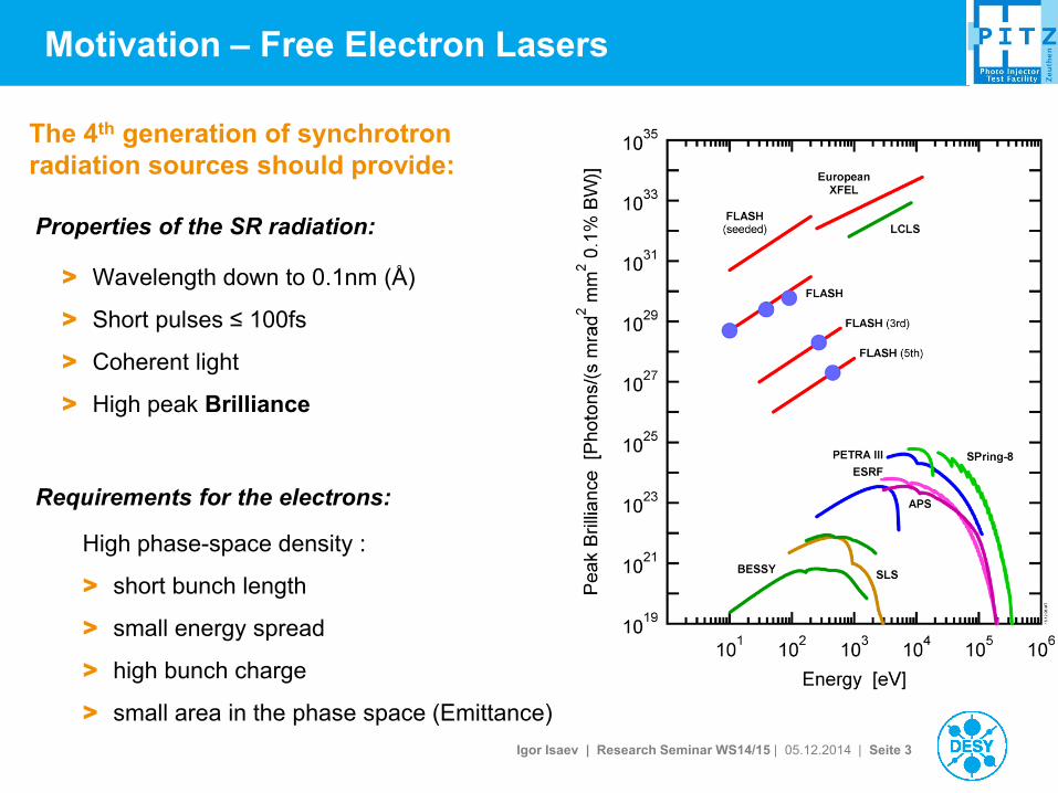
The 4th generation of synchrotron
radiation sources should provide:
Properties of the SR radiation:
Requirements for the electrons:
> Wavelength down to 0.1nm (Å)
> Short pulses ≤ 100fs
> Coherent light
> High peak Brilliance
High phase-space density :
> short bunch length
> small energy spread
> high bunch charge
> small area in the phase space (Emittance)
Igor Isaev | Research Seminar WS14/15 | 05.12.2014 | Seite 4
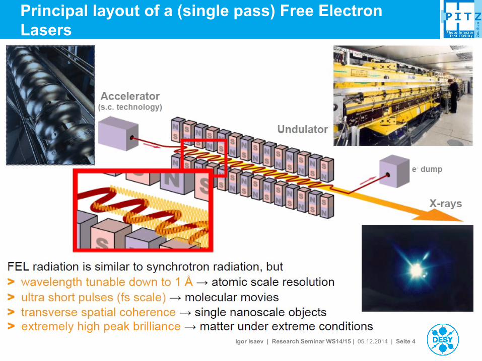
Principal layout of a (single pass) Free Electron
Lasers

Igor Isaev | Research Seminar WS14/15 | 05.12.2014 | Seite 5
FEL performance

Igor Isaev | Research Seminar WS14/15 | 05.12.2014 | Seite 6
Phase space and emittance
• The phase space of the system is the space in which all possible states of the system are
represented.
• Emittance is related to the volume/area occupied by the electron beam in phase space.
• 6D phase space can be split into 3x2D phase spaces: 𝑥, 𝑥′ ; 𝑦, 𝑦′ ; 𝑧, 𝑝𝑧
• Normalized transverse rms emittance for X plane:
𝜀𝑛,𝑥 = 𝛽𝛾 𝑥2 𝑥′2 − 𝑥𝑥′ 2
𝜀𝑛,𝑥𝑦 = 𝜀𝑛,𝑥 𝜀𝑛,𝑦
• Normalized transverse rms emittance
for both planes:
𝛽 =𝑣
𝑐, 𝛾 =
1
1 − 𝛽2 ~
Igor Isaev | Research Seminar WS14/15 | 05.12.2014 | Seite 7
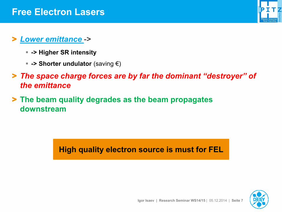
Free Electron Lasers
> Lower emittance ->
-> Higher SR intensity
-> Shorter undulator (saving €)
> The space charge forces are by far the dominant “destroyer” of
the emittance
> The beam quality degrades as the beam propagates
downstream
High quality electron source is must for FEL
Igor Isaev | Research Seminar WS14/15 | 05.12.2014 | Seite 8
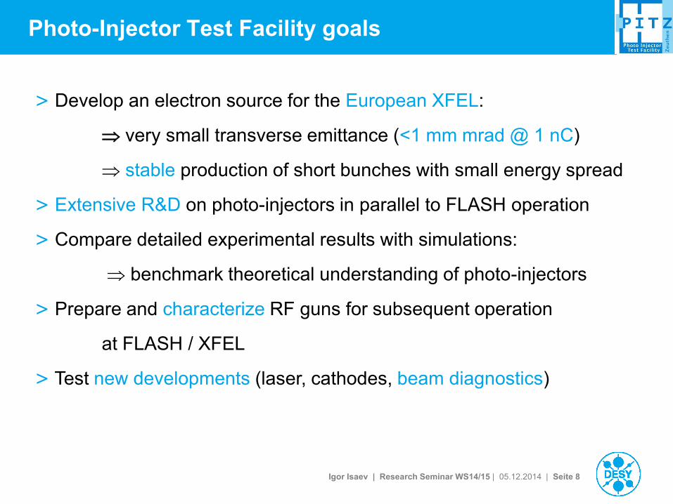
Photo-Injector Test Facility goals
> Develop an electron source for the European XFEL:
very small transverse emittance (<1 mm mrad @ 1 nC)
stable production of short bunches with small energy spread
> Extensive R&D on photo-injectors in parallel to FLASH operation
> Compare detailed experimental results with simulations:
benchmark theoretical understanding of photo-injectors
> Prepare and characterize RF guns for subsequent operation
at FLASH / XFEL
> Test new developments (laser, cathodes, beam diagnostics)
Igor Isaev | Research Seminar WS14/15 | 05.12.2014 | Seite 9
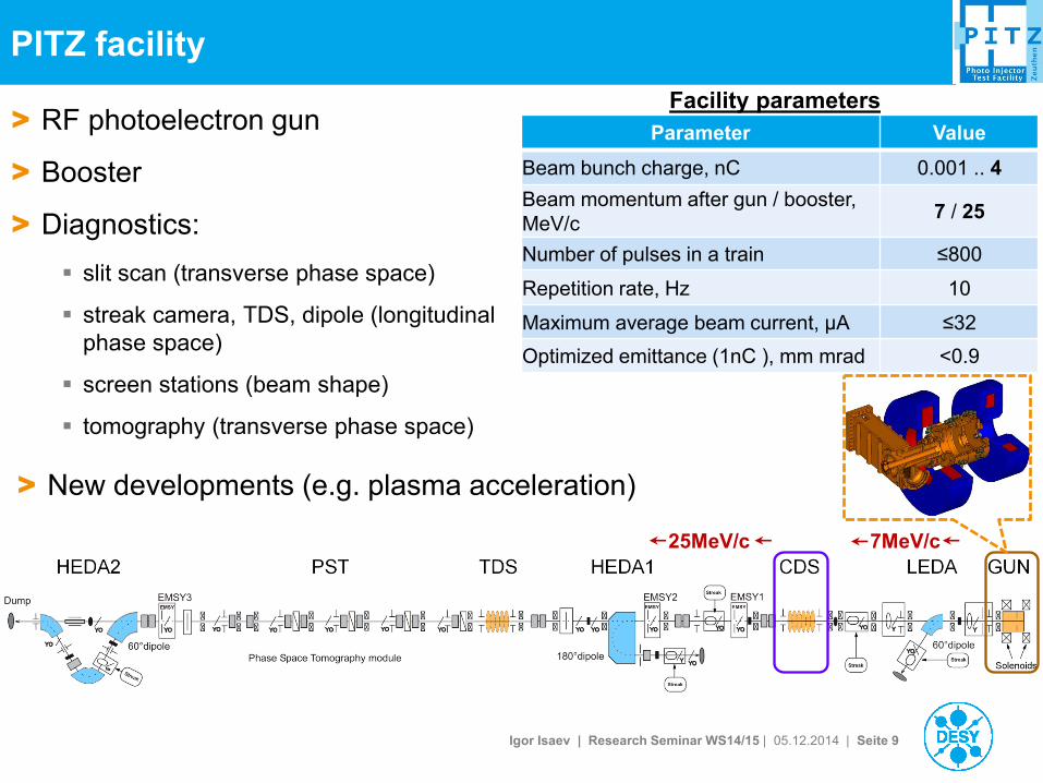
PITZ facility
7MeV/c 25MeV/c
Facility parameters > RF photoelectron gun
> Booster
> Diagnostics:
slit scan (transverse phase space)
streak camera, TDS, dipole (longitudinal
phase space)
screen stations (beam shape)
tomography (transverse phase space)
Parameter Value
Beam bunch charge, nC 0.001 .. 4
Beam momentum after gun / booster,
MeV/c 7 / 25
Number of pulses in a train ≤800
Repetition rate, Hz 10
Maximum average beam current, µA ≤32
Optimized emittance (1nC ), mm mrad <0.9
> New developments (e.g. plasma acceleration)
Igor Isaev | Research Seminar WS14/15 | 05.12.2014 | Seite 10
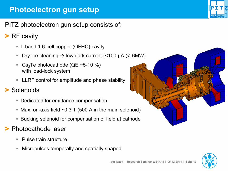
Photoelectron gun setup
PITZ photoelectron gun setup consists of:
> RF cavity
L-band 1.6-cell copper (OFHC) cavity
Dry-ice cleaning → low dark current (<100 µA @ 6MW)
Cs2Te photocathode (QE ~5-10 %)
with load-lock system
LLRF control for amplitude and phase stability
> Solenoids
Dedicated for emittance compensation
Max. on-axis field ~0.3 T (500 A in the main solenoid)
Bucking solenoid for compensation of field at cathode
> Photocathode laser
Pulse train structure
Micropulses temporally and spatially shaped
Igor Isaev | Research Seminar WS14/15 | 05.12.2014 | Seite 11
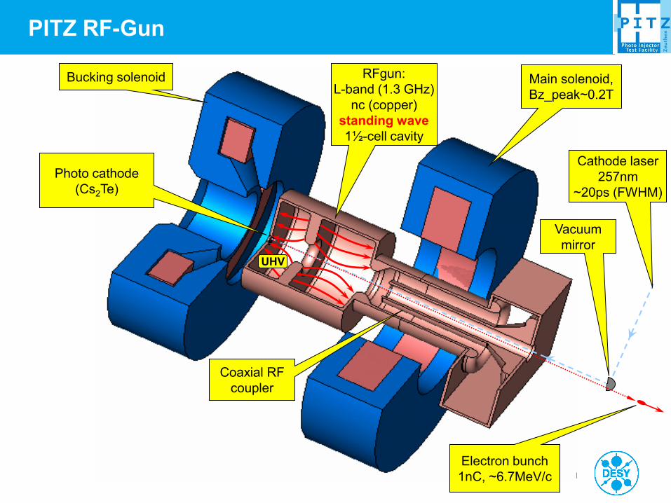
RFgun:
L-band (1.3 GHz)
nc (copper)
standing wave
1½-cell cavity
Main solenoid,
Bz_peak~0.2T
Bucking solenoid
Photo cathode
(Cs2Te)
Coaxial RF
coupler
Cathode laser
257nm
~20ps (FWHM)
Vacuum
mirror
Electron bunch
1nC, ~6.7MeV/c
UHV
PITZ RF-Gun
Igor Isaev | Research Seminar WS14/15 | 05.12.2014 | Seite 12
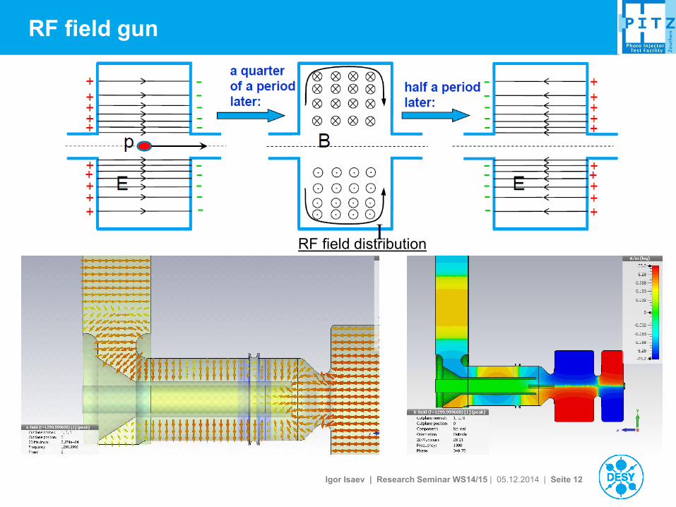
RF field gun
RF field distribution
Igor Isaev | Research Seminar WS14/15 | 05.12.2014 | Seite 13
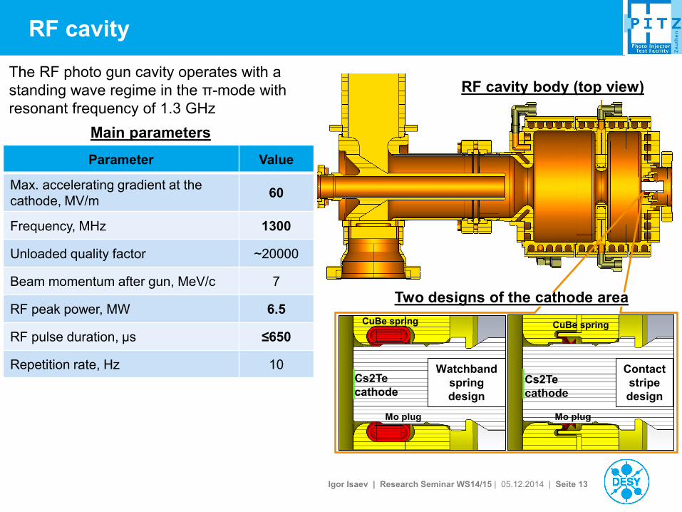
RF cavity
The RF photo gun cavity operates with a
standing wave regime in the π-mode with
resonant frequency of 1.3 GHz
Parameter Value
Max. accelerating gradient at the
cathode, MV/m 60
Frequency, MHz 1300
Unloaded quality factor ~20000
Beam momentum after gun, MeV/c 7
RF peak power, MW 6.5
RF pulse duration, µs ≤650
Repetition rate, Hz 10
Main parameters
RF cavity body (top view)
Two designs of the cathode area
Watchband
spring
design
Contact
stripe
design
Mo plug
CuBe spring
Cs2Te
cathode
Mo plug
CuBe spring
Cs2Te
cathode
Igor Isaev | Research Seminar WS14/15 | 05.12.2014 | Seite 14
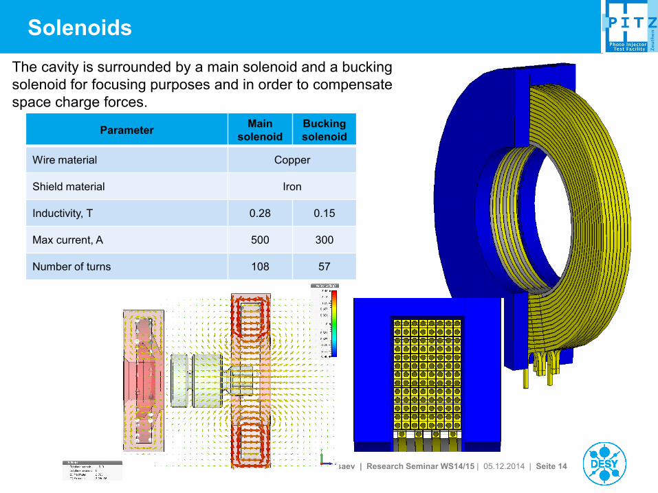
Solenoids
Parameter Main
solenoid
Bucking
solenoid
Wire material Copper
Shield material Iron
Inductivity, T 0.28 0.15
Max current, A 500 300
Number of turns 108 57
The cavity is surrounded by a main solenoid and a bucking
solenoid for focusing purposes and in order to compensate
space charge forces.
Igor Isaev | Research Seminar WS14/15 | 05.12.2014 | Seite 15
15
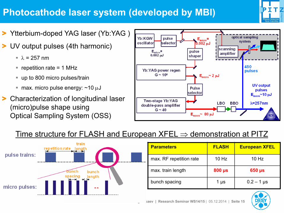
Photocathode laser system (developed by MBI)
> Ytterbium-doped YAG laser (Yb:YAG )
> UV output pulses (4th harmonic)
= 257 nm
repetition rate = 1 MHz
up to 800 micro pulses/train
max. micro pulse energy: ~10 J
> Characterization of longitudinal laser
(micro)pulse shape using
Optical Sampling System (OSS)
Time structure for FLASH and European XFEL demonstration at PITZ
Parameters FLASH European XFEL
max. RF repetition rate 10 Hz 10 Hz
max. train length 800 µs 650 µs
bunch spacing 1 µs 0.2 – 1 µs
Igor Isaev | Research Seminar WS14/15 | 05.12.2014 | Seite 16
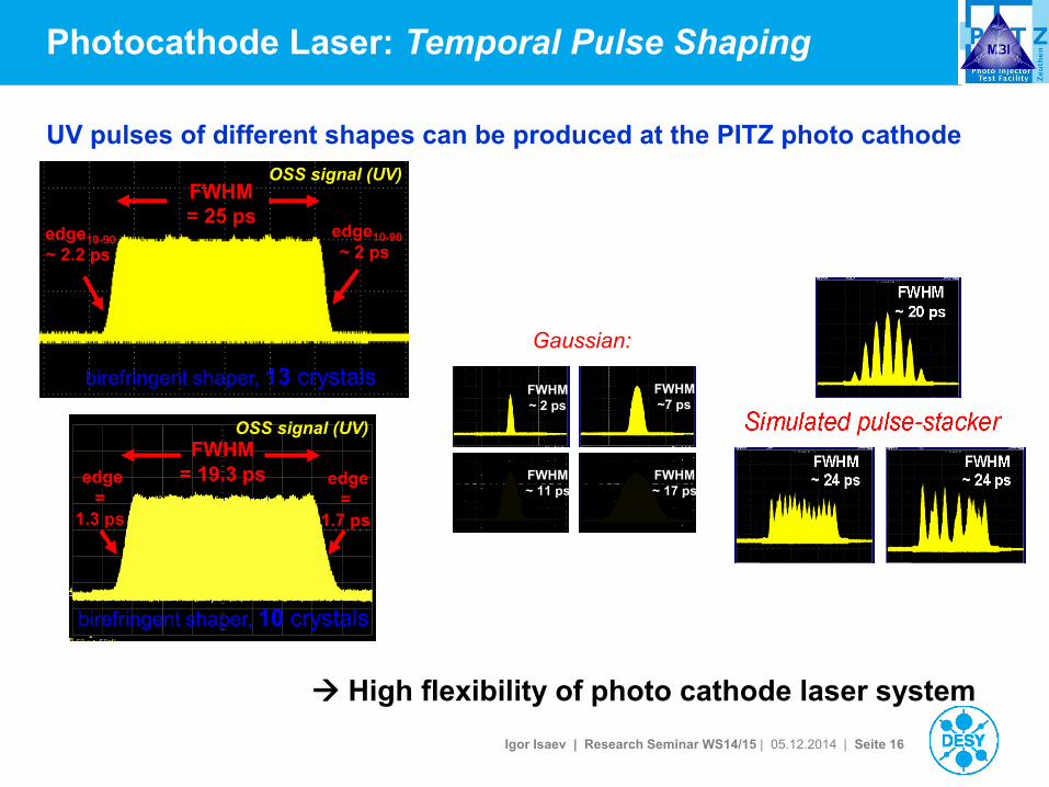
UV pulses of different shapes can be produced at the PITZ photo cathode
FWHM
= 25 ps edge10-90
~ 2.2 ps
edge10-90
~ 2 ps
birefringent shaper, 13 crystals
OSS signal (UV)
OSS signal (UV)
edge
=
1.3 ps
edge
=
1.7 ps
FWHM
= 19.3 ps
birefringent shaper, 10 crystals
High flexibility of photo cathode laser system
Photocathode Laser: Temporal Pulse Shaping
FWHM
~ 11 ps
FWHM
~7 ps
FWHM
~ 17 ps
FWHM
~ 2 ps
FWHM
~ 11 ps
FWHM
~7 ps
FWHM
~ 17 ps
FWHM
~ 2 ps
Gaussian:
Igor Isaev | Research Seminar WS14/15 | 05.12.2014 | Seite 17
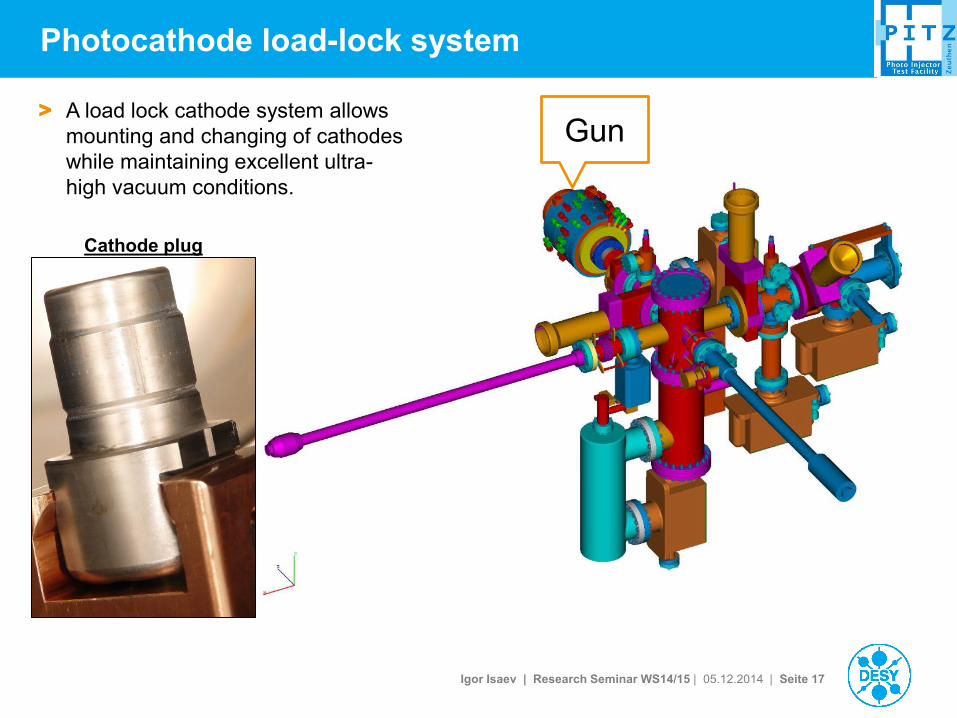
Photocathode load-lock system
> A load lock cathode system allows
mounting and changing of cathodes
while maintaining excellent ultra-
high vacuum conditions.
Gun
Cathode plug
Igor Isaev | Research Seminar WS14/15 | 05.12.2014 | Seite 18
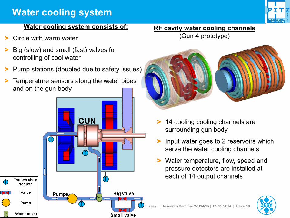
Water cooling system
RF cavity water cooling channels
(Gun 4 prototype)
Water cooling system consists of:
> Circle with warm water
> Big (slow) and small (fast) valves for
controlling of cool water
> Pump stations (doubled due to safety issues)
> Temperature sensors along the water pipes
and on the gun body
> 14 cooling cooling channels are
surrounding gun body
> Input water goes to 2 reservoirs which
serve the water cooling channels
> Water temperature, flow, speed and
pressure detectors are installed at
each of 14 output channels

Igor Isaev | Research Seminar WS14/15 | 05.12.2014 | Seite 19
PMT - Photomultiplier tube
e-det – Electron detector
IGP – Ion getter pump
(pressure reading)
PG - Pressure gauge
RF regulation by FB
loop is possible due
to 10 MW directional
coupler
RF system layout for a gun
Setup used in the period
November 2012 – May 2014
(Gun 3.1, Gun 4.3, Gun 4.4)
Igor Isaev | Research Seminar WS14/15 | 05.12.2014 | Seite 20
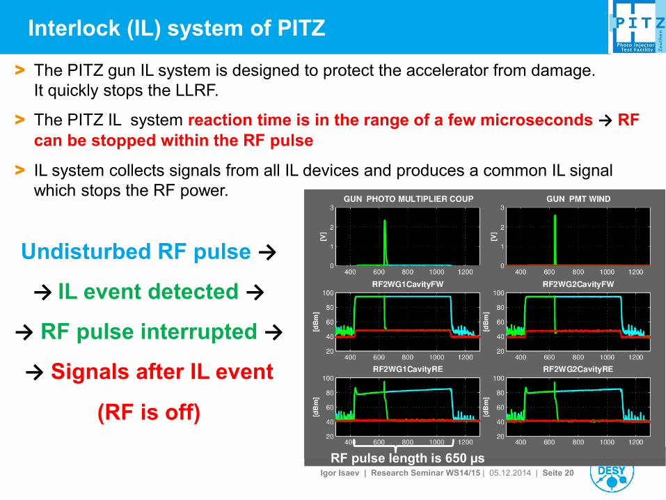
Interlock (IL) system of PITZ
Undisturbed RF pulse →
→ IL event detected →
→ RF pulse interrupted →
→ Signals after IL event
(RF is off)
> The PITZ gun IL system is designed to protect the accelerator from damage.
It quickly stops the LLRF.
> The PITZ IL system reaction time is in the range of a few microseconds → RF
can be stopped within the RF pulse
> IL system collects signals from all IL devices and produces a common IL signal
which stops the RF power.
RF pulse length is 650 µs

Igor Isaev | Research Seminar WS14/15 | 05.12.2014 | Seite 21
Gun tuning
Measurement Setup
Measurements:
> Frequency tuning
> Measure -mode and 0-mode frequencies using S11
> Measure Q-values for -mode and 0-mode
> Bead-pull Measurements
Igor Isaev | Research Seminar WS14/15 | 05.12.2014 | Seite 22
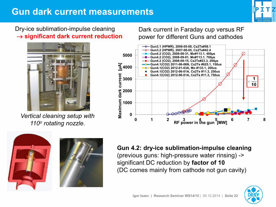
Gun dark current measurements
Dark current in Faraday cup versus RF
power for different Guns and cathodes
Dry-ice sublimation-impulse cleaning
significant dark current reduction
Vertical cleaning setup with
110o rotating nozzle.
0
1000
2000
3000
4000
5000
0 1 2 3 4 5 6 7 8M
axim
um
dark
cu
rre
nt
[µ
A]
RF power in the gun [MW]
Gun3.1 (HPWR), 2006-05-08, Cs2Te#58.1Gun3.2 (HPWR), 2007-08-05, Cs2Te#42.4Gun4.2 (CO2), 2008-08-31, Mo#113.1, 400µsGun4.2 (CO2), 2008-09-01, Mo#113.1, 700µsGun4.2 (CO2), 2008-09-15, Cs2Te#23.3, 200µsGun4.1(CO2) 2011-06-06N, Cs2Te #625.1, 150usGun4.1(CO2) 2012-01-03A, Mo #133.1, 200usGun4.1(CO2) 2012-06-01A, Cs2Te #11.3, 250usGun4.1(CO2) 2012-06-01A, Cs2Te #11.3, 750us
Gun 4.2: dry-ice sublimation-impulse cleaning
(previous guns: high-pressure water rinsing) ->
significant DC reduction by factor of 10
(DC comes mainly from cathode not gun cavity)
Igor Isaev | Research Seminar WS14/15 | 05.12.2014 | Seite 23
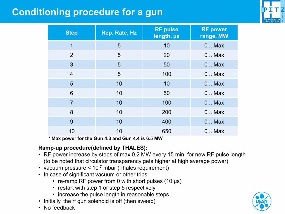
Conditioning procedure for a gun
Step Rep. Rate, Hz RF pulse
length, µs
RF power
range, MW
1 5 10 0 .. Max
2 5 20 0 .. Max
3 5 50 0 .. Max
4 5 100 0 .. Max
5 10 10 0 .. Max
6 10 50 0 .. Max
7 10 100 0 .. Max
8 10 200 0 .. Max
9 10 400 0 .. Max
10 10 650 0 .. Max
* Max power for the Gun 4.3 and Gun 4.4 is 6.5 MW
Ramp-up procedure(defined by THALES):
• RF power increase by steps of max 0.2 MW every 15 min. for new RF pulse length
(to be noted that circulator transparency gets higher at high average power)
• vacuum pressure < 10-7 mbar (Thales requirement)
• In case of significant vacuum or other trips:
• re-ramp RF power from 0 with short pulses (10 µs)
• restart with step 1 or step 5 respectively
• increase the pulse length in reasonable steps
• Initially, the rf gun solenoid is off (then sweep)
• No feedback

Igor Isaev | Research Seminar WS14/15 | 05.12.2014 | Seite 24
Beginning of Gun 4.4 run history
(from 08.10.2013 until 02.12.2013)
Repetition rate
was changed from
5Hz to 10Hz
Igor Isaev | Research Seminar WS14/15 | 05.12.2014 | Seite 25
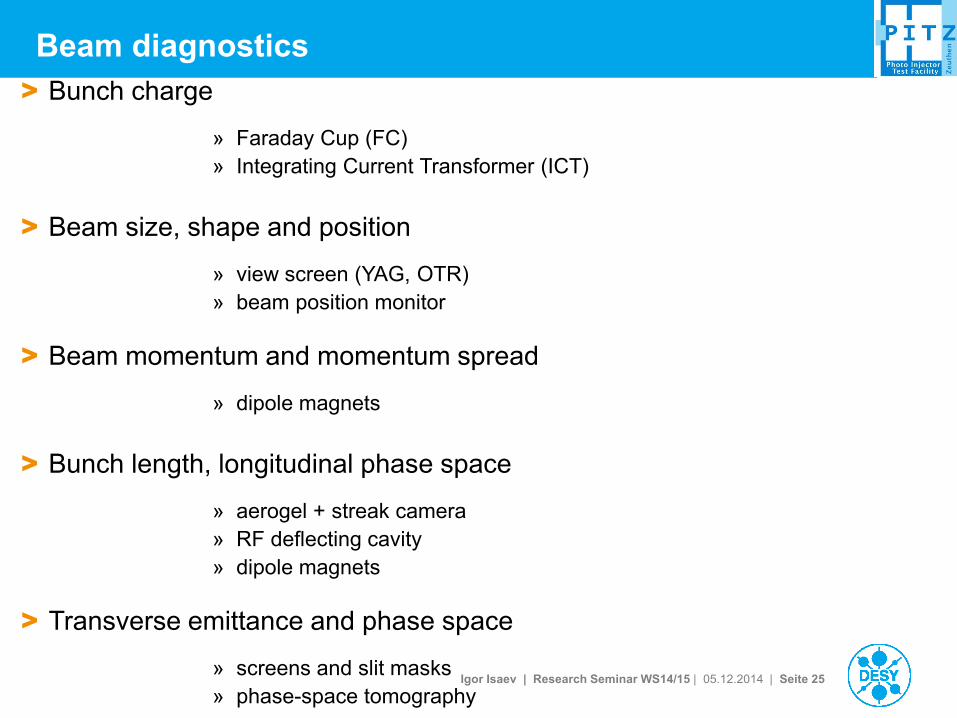
> Bunch charge
» Faraday Cup (FC)
» Integrating Current Transformer (ICT)
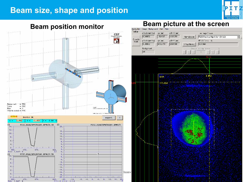
> Beam size, shape and position
» view screen (YAG, OTR)
» beam position monitor
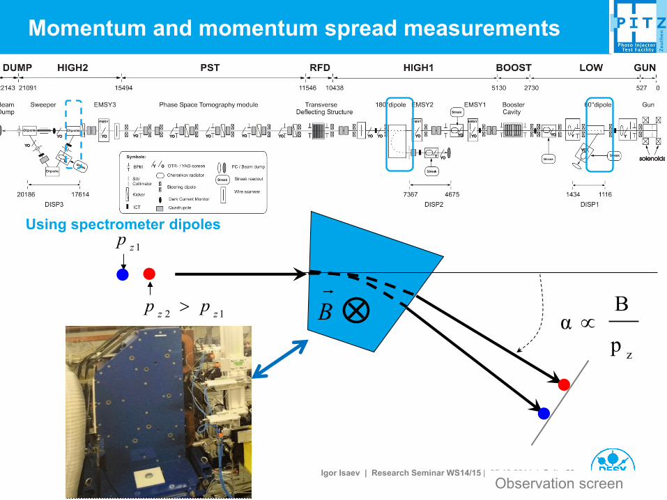
> Beam momentum and momentum spread
» dipole magnets
> Bunch length, longitudinal phase space
» aerogel + streak camera
» RF deflecting cavity
» dipole magnets
> Transverse emittance and phase space
» screens and slit masks
» phase-space tomography
Beam diagnostics
Igor Isaev | Research Seminar WS14/15 | 05.12.2014 | Seite 26
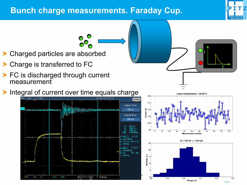
t
I > Charged particles are absorbed
> Charge is transferred to FC
> FC is discharged through current measurement
> Integral of current over time equals charge
Bunch charge measurements. Faraday Cup.
Igor Isaev | Research Seminar WS14/15 | 05.12.2014 | Seite 27
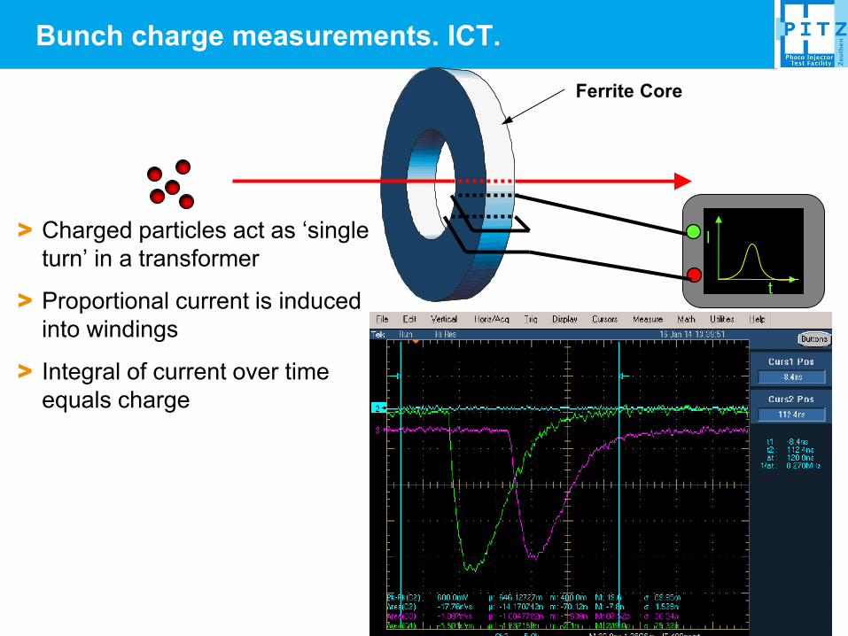
> Charged particles act as ‘single
turn’ in a transformer
> Proportional current is induced
into windings
> Integral of current over time
equals charge
t
I
Ferrite Core
Bunch charge measurements. ICT.
Igor Isaev | Research Seminar WS14/15 | 05.12.2014 | Seite 28
Beam size, shape and position
Beam position monitor Beam picture at the screen
Igor Isaev | Research Seminar WS14/15 | 05.12.2014 | Seite 29
Observation screen
Momentum and momentum spread measurements
Using spectrometer dipoles
zp
Bα B
1zp
12 zzpp
Igor Isaev | Research Seminar WS14/15 | 05.12.2014 | Seite 30
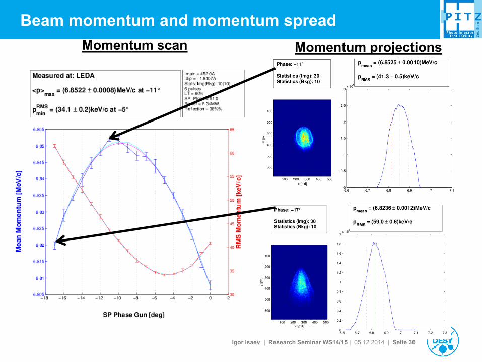
Beam momentum and momentum spread
Momentum scan Momentum projections
Igor Isaev | Research Seminar WS14/15 | 05.12.2014 | Seite 31
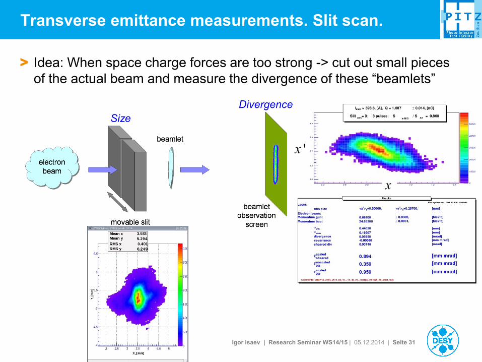
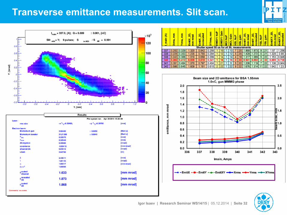
Transverse emittance measurements. Slit scan.
> Idea: When space charge forces are too strong -> cut out small pieces
of the actual beam and measure the divergence of these “beamlets”
x
'x
Size
Divergence
Igor Isaev | Research Seminar WS14/15 | 05.12.2014 | Seite 32
Transverse emittance measurements. Slit scan.
Igor Isaev | Research Seminar WS14/15 | 05.12.2014 | Seite 33
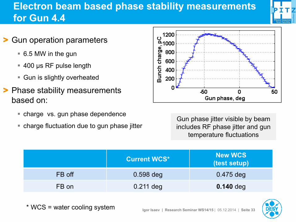
> Gun operation parameters
6.5 MW in the gun
400 µs RF pulse length
Gun is slightly overheated
> Phase stability measurements
based on:
charge vs. gun phase dependence
charge fluctuation due to gun phase jitter
Electron beam based phase stability measurements
for Gun 4.4
Current WCS* New WCS
(test setup)
FB off 0.598 deg 0.475 deg
FB on 0.211 deg 0.140 deg
* WCS = water cooling system
Gun phase jitter visible by beam
includes RF phase jitter and gun
temperature fluctuations
Igor Isaev | Research Seminar WS14/15 | 05.12.2014 | Seite 34
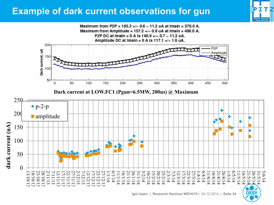
Example of dark current observations for gun
0
50
100
150
200
250
13/10/13
18/10/13
23/10/13
28/10/13
2/11/13
7/11/13
12/11/13
17/11/13
22/11/13
27/11/13
2/12/13
7/12/13
12/12/13
17/12/13
22/12/13
27/12/13
1/1/14
6/1/14
11/1/14
16/1/14
21/1/14
26/1/14
31/1/14
5/2/14
10/2/14
15/2/14
20/2/14
25/2/14
2/3/14
7/3/14
12/3/14
17/3/14
22/3/14
27/3/14
1/4/14
6/4/14
11/4/14
16/4/14
21/4/14
26/4/14
1/5/14
6/5/14
11/5/14
16/5/14
21/5/14
26/5/14
31/5/14
5/6/14
da
rk c
urr
ent
(uA
)
Dark current at LOW.FC1 (Pgun=6.5MW, 200us) @ Maximum
p-2-p
amplitude

Igor Isaev | Research Seminar WS14/15 | 05.12.2014 | Seite 35
Gun 4.3 DC@450A Gun 4.3 DC@430A
Gun 4.3 DC@400A Gun 4.3 DC@350A
Igor Isaev | Research Seminar WS14/15 | 05.12.2014 | Seite 36
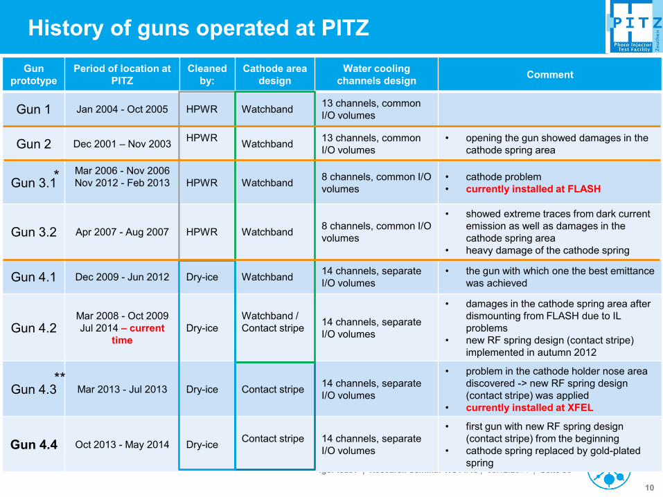
History of guns operated at PITZ
Gun
prototype
Period of location at
PITZ
Cleaned
by:
Cathode area
design
Water cooling
channels design Comment
Gun 1 Jan 2004 - Oct 2005 HPWR Watchband 13 channels, common
I/O volumes
Gun 2 Dec 2001 – Nov 2003 HPWR
Watchband
13 channels, common
I/O volumes
• opening the gun showed damages in the
cathode spring area
Gun 3.1 Mar 2006 - Nov 2006
Nov 2012 - Feb 2013
HPWR Watchband 8 channels, common I/O
volumes
• cathode problem
• currently installed at FLASH
Gun 3.2 Apr 2007 - Aug 2007 HPWR Watchband 8 channels, common I/O
volumes
• showed extreme traces from dark current
emission as well as damages in the
cathode spring area
• heavy damage of the cathode spring
Gun 4.1 Dec 2009 - Jun 2012 Dry-ice Watchband 14 channels, separate
I/O volumes
• the gun with which one the best emittance
was achieved
Gun 4.2 Mar 2008 - Oct 2009
Jul 2014 – current
time
Dry-ice
Watchband /
Contact stripe
14 channels, separate
I/O volumes
• damages in the cathode spring area after
dismounting from FLASH due to IL
problems
• new RF spring design (contact stripe)
implemented in autumn 2012
Gun 4.3 Mar 2013 - Jul 2013 Dry-ice Contact stripe 14 channels, separate
I/O volumes
• problem in the cathode holder nose area
discovered -> new RF spring design
(contact stripe) was applied
• currently installed at XFEL
Gun 4.4 Oct 2013 - May 2014 Dry-ice Contact stripe
14 channels, separate
I/O volumes
• first gun with new RF spring design
(contact stripe) from the beginning
• cathode spring replaced by gold-plated
spring
**
*
10

Igor Isaev | Research Seminar WS14/15 | 05.12.2014 | Seite 37
Acknowledgements
PITZ Team DESY Zeuthen:
F. Stephan, M. Krasilnikov, G. Asova, H.-J. Grabosch, M. Groß, L. Hakobyan, I. Isaev, Y.
Ivanisenko, L. Jachmann, M. Khojoyan, G. Klemz, W. Köhler, M. Krasilnikov, M. Mahgoub, D.
Malyutin, M. Nozdrin, A. Oppelt, M. Otevrel, B. Petrosyan, S. Rimjaem, A. Shapovalov,, G.
Vashchenko, S. Weidinger, R. Wenndorff
DESY, Hamburg: K. Flöttmann, M. Hoffmann, S. Lederer, H. Schlarb, S. Schreiber
MBI, Berlin: I. Templin, I. Will
INR, Moscow: V. Paramonov
HZB, Berlin: D. Richter
With contributions from PITZ partners:
DESY (Hamburg); Hamburg University; HZB (Berlin); INFN (Milan, Italy); INR (Troitsk, Russia);
INRNE (Sofia, Bulgaria); LAL(Orsay, France ); MBI(Berlin); STFC (Daresbury, UK); TUD
(Darmstadt);
ThEP (Thailand); YERPHI (Yerevan, Armenia)
Igor Isaev | Research Seminar WS14/15 | 05.12.2014 | Seite 38
Thank you for your attention.
Igor Isaev | Research Seminar WS14/15 | 05.12.2014 | Seite 39
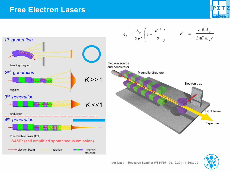
Free Electron Lasers
21
2
2
2
Ku
L
cm
BeK
e
u
2
K >> 1
K <<1
SASE: (self amplified spontaneous emission)
1st generation
2nd generation
4th generation
3rd generation
Igor Isaev | Research Seminar WS14/15 | 05.12.2014 | Seite 40
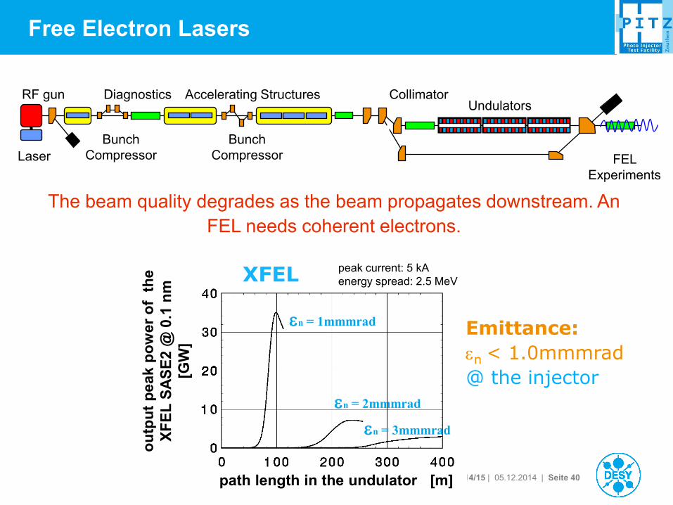
Free Electron Lasers
en = 1mmmrad
ou
tpu
t p
ea
k p
ow
er
of
th
e
XF
EL
SA
SE
2 @
0.1
nm
[GW
]
path length in the undulator [m]
en = 2mmmrad
en = 3mmmrad
peak current: 5 kA
energy spread: 2.5 MeV XFEL
Emittance:
en < 1.0mmmrad
@ the injector
RF gun
Laser
Bunch
Compressor
Undulators Collimator
Bunch
Compressor
Accelerating Structures Diagnostics
FEL
Experiments
The beam quality degrades as the beam propagates downstream. An
FEL needs coherent electrons.
Igor Isaev | Research Seminar WS14/15 | 05.12.2014 | Seite 41
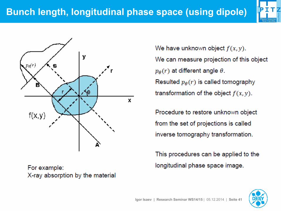
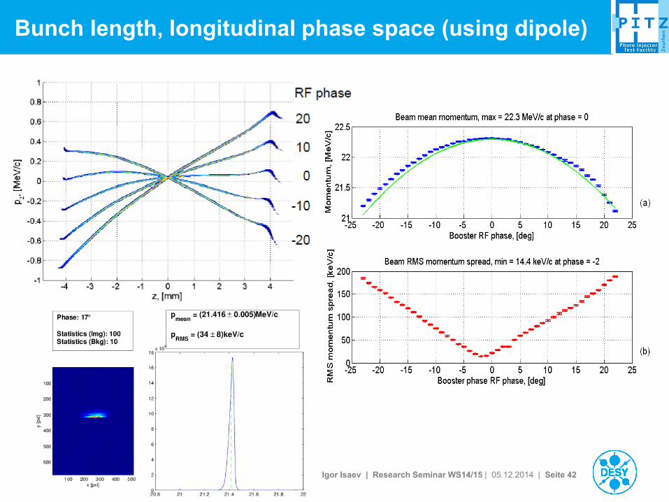
Bunch length, longitudinal phase space (using dipole)
Igor Isaev | Research Seminar WS14/15 | 05.12.2014 | Seite 42
Bunch length, longitudinal phase space (using dipole)
Igor Isaev | Research Seminar WS14/15 | 05.12.2014 | Seite 43
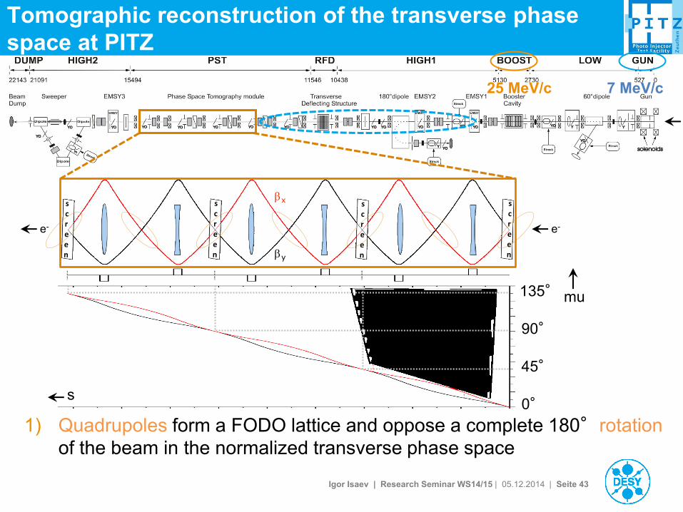
Tomographic reconstruction of the transverse phase
space at PITZ
1) Quadrupoles form a FODO lattice and oppose a complete 180°rotation
of the beam in the normalized transverse phase space
25 MeV/c 7 MeV/c
x
y
e- e-
135°
90°
45°
s
mu
0°

Igor Isaev | Research Seminar WS14/15 | 05.12.2014 | Seite 44
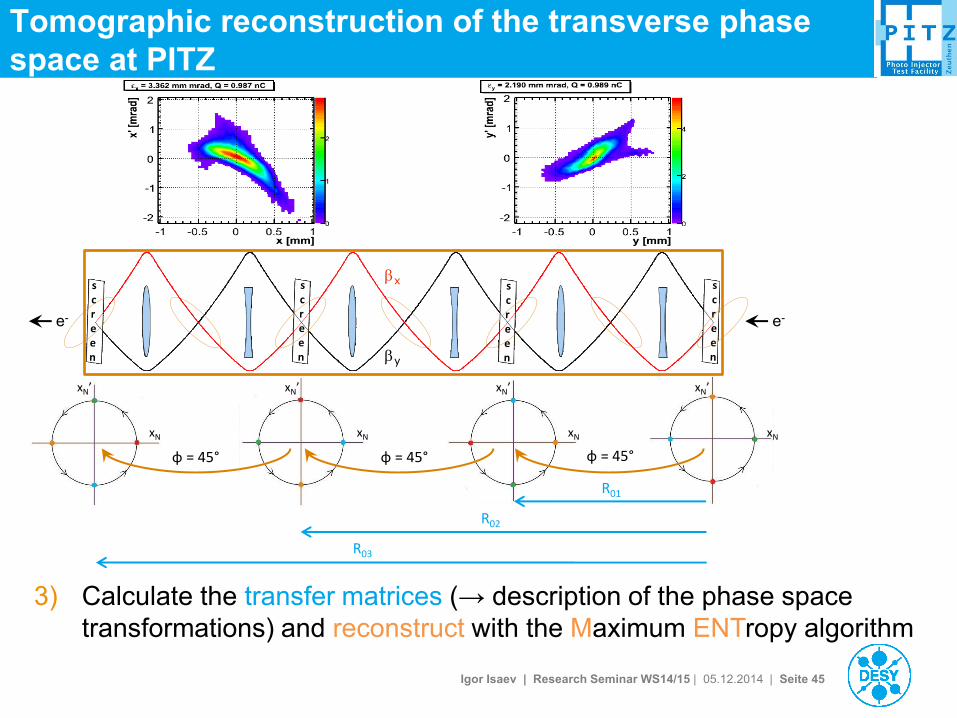
Tomographic reconstruction of the transverse phase
space at PITZ
x
y
φ = 45° φ = 45° φ = 45°
e- e-
2) At equidistant phase advance values ( ≈ rotation angles) the screens
capture the beam profile, creating projections of both transverse planes
xN
xN’
xN
xN’
xN
xN’
xN
xN’
Igor Isaev | Research Seminar WS14/15 | 05.12.2014 | Seite 45
Tomographic reconstruction of the transverse phase
space at PITZ
x
y
e- e-
3) Calculate the transfer matrices (→ description of the phase space
transformations) and reconstruct with the Maximum ENTropy algorithm
φ = 45° φ = 45° φ = 45°
xN
xN’
xN
xN’
xN
xN’
xN
xN’
R01
R02
R03


